noise control fo buildings
DESCRIPTION
sound insulation strategies for buildingsTRANSCRIPT
1
C e r t a i nTe e d
Guidelines for Acoustical Problem Solving
NOISE CONTROL FOR BUILDINGS
“The technology of noise control both inside and outside buildings
is well developed today.
The problem is that it is too seldom used.”
Robert B. Newman, Architect

1
I Introduction The problem of noise in the built environment .....................................................................................................2 There are solutions .............................................................................................................................................2 Who is CertainTeed? ..........................................................................................................................................2 Some historical milestones .................................................................................................................................3
II Fundamentals of acoustics Properties of sound: frequency, wavelength, amplitude ..................................................................................4, 5 How we measure sound; how we hear sound ....................................................................................................6 Other sound properties: duration, propagation ...............................................................................................6, 7 How much sound is acceptable? Noise criteria (NC) values ................................................................................7 Sound paths, airborne and structureborne .........................................................................................................8
III Airborne sound transmission Sound transmission loss, sound transmission class (STC) ..................................................................................9 Lightweight double-leaf walls ........................................................................................................................9, 10 Insulation density and STC ...............................................................................................................................11 Sound transmission loss and noise control .......................................................................................................11 Sound fl anking paths ........................................................................................................................................11
IV Structureborne sound transmission Impact insulation class (IIC) ..............................................................................................................................12
V Sound absorption Defi nition; measurement of sound absorption ..................................................................................................13 Properties of sound absorbers .........................................................................................................................13 Sound absorption and noise control .................................................................................................................14 Sound level reduction calculation .....................................................................................................................15 Reverberation time calculation ..........................................................................................................................15
VI Principles of SPR noise control Controlling noise at the source .........................................................................................................................16 Controlling noise along its path .........................................................................................................................16 Controlling noise at the receiver ........................................................................................................................17 Temporary sound control .................................................................................................................................17 Three steps to noise control solutions ..............................................................................................................17
VII HVAC noise control Fiber glass duct liner ........................................................................................................................................18 Fiber glass duct board .....................................................................................................................................18
VIII Residential sound control practices The right insulation material ..............................................................................................................................19 Five noise control mistakes to avoid .................................................................................................................20
IX Building insulation assemblies Sound absorption coeffi cients, typical building materials ..................................................................................21 Sound absorption coeffi cients, CertainTeed fi ber glass insulations ..............................................................21, 22 Sound transmission loss values, common building materials ............................................................................23 Sound transmission loss values, wood stud wall assemblies ..........................................................23, 24, 25, 26 Sound transmission loss values, steel stud wall assemblies ........................................................................27, 28
X Appendix Acoustical guide specifi cation .....................................................................................................................29, 30 Glossary of terms .......................................................................................................................................30, 31 Worksheet for calculation of room reverberation level and time .........................................................................32 Fire rated wall assemblies .................................................................................................................................33 CertainTeed acoustical products ...................................................................................................................... 34
NOTE: In preparing this manual, CertainTeed Corporation has taken care to include accurately all information relevant to basic application of noise control products and systems. However, because of the many variables that may arise in construction technology, the importance of correct installation of acoustical materials, and other factors including use and occupancy, no liability can be assumed for application of the principles and techniques contained herein. CertainTeed Corporation makes no warranty, express or implied or regarding merchantability or fi tness for a particular purpose, in connection with the information supplied herein.
CONTENTS
2
The problem of noise in the built environment
It’s a noisy world. Twenty-four hours a day, seven days a week, we are exposed to sounds we do not want, need, or benefi t from. There are few places on the planet where in our daily lives we are free from unwanted sounds.
Noise from many outdoor sources assails our hearing as it invades our homes and workplaces: traffi c, aircraft, barking dogs, neighbors’ voices. Noise within the workplace — from offi ce machines, telephones, ventilating systems, unwanted conversation in the next cubicle — distracts us from our work and makes us less productive.
Noise from within the home — from appliances, upstairs footsteps, TV sound traveling from room to room — keeps our homes from being the restful refuges they ought to be. Noise in the classroom impedes the learning process and threatens our children’s educational experience.
Noise can frustrate and impede speech communication. It can imperil us as we walk or drive city streets. It can be a physical health hazard as well: Exposure to high noise levels can cause permanent hearing loss.
In short: Noise is unwanted sound.
There are solutions
We don’t need to suffer the distracting, fatiguing, and unhealthful consequences of noise. There are practical and economical solutions to almost all noise problems in the built environment. To approach the solution to any specifi c noise problem, we need to:
1. Understand the basic physics of acoustics and how noise — unwanted sound — is produced, how it propagates, and how it is controlled.
2. Learn the basics of noise control, and how to approach the problem from three standpoints: the source of noise, the path it travels, and the point of reception.
3. Become familiar with, and discover how to apply in both new and remodeling construction, the acoustical products and systems that control noise — products that contribute to the creation of acoustically comfortable, productive, and healthful environments.
That’s what architects, engineers, contractors, and building owners — anyone concerned with solving noise control problems in all types of buildings — will fi nd in this manual. It includes information on how to solve specifi c noise control problems using CertainTeed® acoustical products and systems. These products are made of the most versatile, cost-effective, safe, and easily applied sound control material yet devised: fi ber glass.
Who is CertainTeed?
CertainTeed Corporation is a member of the Compagnie de Saint-Gobain family, a recognized global leader in high performance building materials technology and the world’s preeminent manufacturer of fi ber glass insulation
products. CertainTeed’s Insulation Group manufactures and markets a complete line of fi ber glass thermal and acoustical insulation products which include:
• CertaPro™ insulation products for commercial construction.
• CertainTeed insulations for use in residential construction.
• CertaSpray® open and closed cell spray foam insulation
• CertainTeed HVAC products for commercial and residential air duct systems.
Through the responsible development of innovative and sustainable building products, CertainTeed has helped shape the building products industry for more than 100 years. Founded in 1904 as General Roofi ng Manufacturing Company, the fi rm’s slogan “Quality Made Certain, Satisfaction Guaranteed,” quickly inspired the name CertainTeed. Today, CertainTeed is North America’s leading brand of exterior and interior building products, including roofi ng, siding, windows, fence, decking, railing, trim, foundations, pipe, insulation, gypsum, and ceilings.
CertainTeed was the fi rst fi ber glass insulation manufacturer to be recognized by the EPA/DOE as an ENERGY STAR® Partner of the Year, and the fi rst in the United States to have its manufacturing plants registered to ISO 9001-2000 standards. Certifi cation indicates third-party verifi cation of implemented quality assurance practices as defi ned in the ISO standard, including document control, training requirements, management review, and system auditing. Product quality and conformance to specifi cations are continuously monitored in our research and development center and in the quality control laboratories at all our manufacturing facilities.
CertainTeed fi ber glass insulation products are also certifi ed by the GREENGUARD® Environmental Institute for low emissions of VOCs, formaldehyde, and other particulates.
CertainTeed acoustical insulation products provide another important benefi t in residential and commercial construction: energy conservation. The high thermal effi ciency of our
fi ber glass insulation products means less energy is required to heat and cool our buildings. This reduces the amount of greenhouse gases from the burning of fossil fuels. All CertainTeed insulation products are qualifi ed to meet the standards of the EPA and the Department of Energy ENERGY STAR conservation program and to display the ENERGY STAR Seal and Insulate partner logo.
If you need assistance in solving noise control problems through application of CertainTeed acoustical products, please contact us at 1-800-233-8990. More information on CertainTeed’s building products and systems is also available at our website, www.certainteed.com/insulation.
I. INTRODUCTION
3
Some historical milestones
Take a seat — any seat — in the great semicircular outdoor amphitheater at Epidaurus, in Greece. Place a player at the center of the performance space. Listen closely: You can almost hear a whisper from as far as 200 feet away. The Greeks knew enough about how sound propagates to have achieved this astonishing acoustical success as long ago as the 5th century B.C.
The Romans could design interiors with ideal acoustics. Stand against the wall in Rome’s Pantheon and your breathing can be heard by someone standing opposite you across the great hemispherical space. The cathedral builders of Europe’s Middle Ages knew how to build for maximum acoustical effect. Sir Christopher Wren and other 18th century architects discovered how to design concert halls to optimize the listening experience at any seat.
Still, little was known about the physical science and measurement of sound until Sir Isaac Newton. He demonstrated that sound waves travel through any medium — solid, liquid, or gaseous — and that the speed with which they propagate depends upon the elasticity and density of the medium.
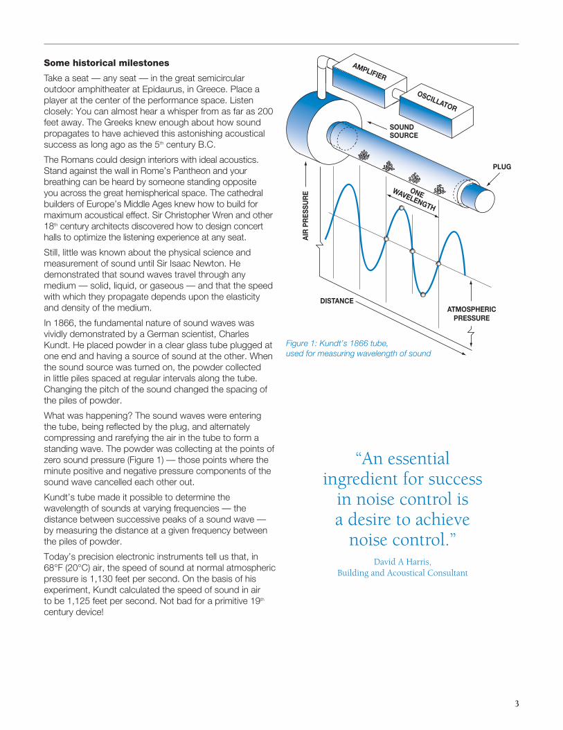
In 1866, the fundamental nature of sound waves was vividly demonstrated by a German scientist, Charles Kundt. He placed powder in a clear glass tube plugged at one end and having a source of sound at the other. When the sound source was turned on, the powder collected in little piles spaced at regular intervals along the tube. Changing the pitch of the sound changed the spacing of the piles of powder.
What was happening? The sound waves were entering the tube, being refl ected by the plug, and alternately compressing and rarefying the air in the tube to form a standing wave. The powder was collecting at the points of zero sound pressure (Figure 1) — those points where the minute positive and negative pressure components of the sound wave cancelled each other out.
Kundt’s tube made it possible to determine the wavelength of sounds at varying frequencies — the distance between successive peaks of a sound wave — by measuring the distance at a given frequency between the piles of powder.
Today’s precision electronic instruments tell us that, in 68°F (20°C) air, the speed of sound at normal atmospheric pressure is 1,130 feet per second. On the basis of his experiment, Kundt calculated the speed of sound in air to be 1,125 feet per second. Not bad for a primitive 19th century device!
PLUG
AMPLIFIER
OSCILLATOR
DISTANCE
SOUNDSOURCE
AIR
PR
ESSU
RE ONE
WAVELENGTH
ATMOSPHERIC PRESSURE
Figure 1: Kundt’s 1866 tube, used for measuring wavelength of sound
“An essential ingredient for success
in noise control is a desire to achieve
noise control.”David A Harris,
Building and Acoustical Consultant
4
Properties of sound
To control sound in today’s built environment, we need to know a little about its fundamental properties such as:
• Frequency (pitch)
• Wavelength
• Amplitude (loudness)
Once these fundamental properties of sound or sound waves are understood, we can proceed to implement effective noise control measures.
Frequency (pitch)
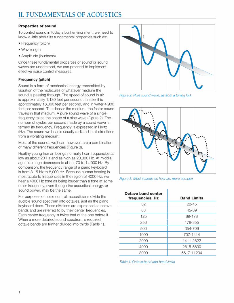
Sound is a form of mechanical energy transmitted by vibration of the molecules of whatever medium the sound is passing through. The speed of sound in air is approximately 1,130 feet per second. In steel it is approximately 16,360 feet per second, and in water 4,900 feet per second. The denser the medium, the faster sound travels in that medium. A pure sound wave of a single frequency takes the shape of a sine wave (Figure 2). The number of cycles per second made by a sound wave is termed its frequency. Frequency is expressed in Hertz (Hz). The sound we hear is usually radiated in all directions from a vibrating medium.
Most of the sounds we hear, however, are a combination of many different frequencies (Figure 3).
Healthy young human beings normally hear frequencies as low as about 20 Hz and as high as 20,000 Hz. At middle age this range decreases to about 70 to 14,000 Hz. By comparison, the frequency range of a piano keyboard is from 31.5 Hz to 8,000 Hz. Because human hearing is most acute to frequencies in the region of 4000 Hz, we hear a 4000 Hz tone as being louder than a tone at some other frequency, even though the acoustical energy, or sound power, may be the same.
For purposes of noise control, acousticians divide the audible sound spectrum into octaves, just as the piano keyboard does. These divisions are expressed as octave bands and are referred to by their center frequencies. Each center frequency is twice that of the one before it. When a more detailed sound spectrum is required, octave bands are further divided into thirds (Table 1).
Figure 3: Most sounds we hear are more complex
Figure 2: Pure sound wave, as from a tuning fork
f2
II. FUNDAMENTALS OF ACOUSTICS
Octave band center frequencies, Hz Band Limits
32 22-45
63 45-89
125 89-178
250 178-355
500 354-709
1000 707-1414
2000 1411-2822
4000 2815-5630
8000 5617-11234
Table 1: Octave band and band limits
5
Wavelength
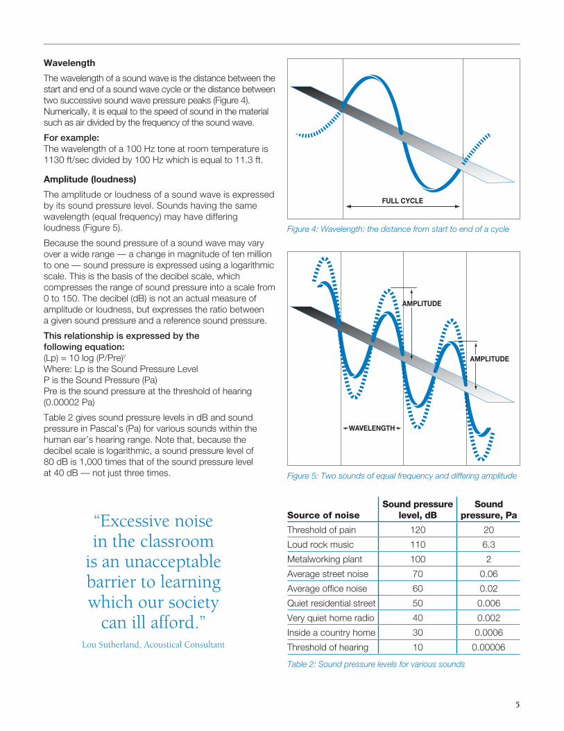
The wavelength of a sound wave is the distance between the start and end of a sound wave cycle or the distance between two successive sound wave pressure peaks (Figure 4). Numerically, it is equal to the speed of sound in the material such as air divided by the frequency of the sound wave.
For example: The wavelength of a 100 Hz tone at room temperature is 1130 ft/sec divided by 100 Hz which is equal to 11.3 ft.
Amplitude (loudness)
The amplitude or loudness of a sound wave is expressed by its sound pressure level. Sounds having the same wavelength (equal frequency) may have differing loudness (Figure 5).
Because the sound pressure of a sound wave may vary over a wide range — a change in magnitude of ten million to one — sound pressure is expressed using a logarithmic scale. This is the basis of the decibel scale, which compresses the range of sound pressure into a scale from 0 to 150. The decibel (dB) is not an actual measure of amplitude or loudness, but expresses the ratio between a given sound pressure and a reference sound pressure.
This relationship is expressed by the following equation: (Lp) = 10 log (P/Pre)2
Where: Lp is the Sound Pressure LevelP is the Sound Pressure (Pa)Pre is the sound pressure at the threshold of hearing (0.00002 Pa)
Table 2 gives sound pressure levels in dB and sound pressure in Pascal’s (Pa) for various sounds within the human ear’s hearing range. Note that, because the decibel scale is logarithmic, a sound pressure level of 80 dB is 1,000 times that of the sound pressure level at 40 dB — not just three times. Figure 5: Two sounds of equal frequency and differing amplitude
WAVELENGTH
AMPLITUDE
AMPLITUDE
Figure 4: Wavelength: the distance from start to end of a cycle
FULL CYCLE
“Excessive noise in the classroom
is an unacceptable barrier to learning which our society
can ill afford.”Lou Sutherland, Acoustical Consultant
Source of noiseSound pressure
level, dBSound
pressure, Pa
Threshold of pain 120 20
Loud rock music 110 6.3
Metalworking plant 100 2
Average street noise 70 0.06
Average offi ce noise 60 0.02
Quiet residential street 50 0.006
Very quiet home radio 40 0.002
Inside a country home 30 0.0006
Threshold of hearing 10 0.00006
Table 2: Sound pressure levels for various sounds
6
How we measure sound levels
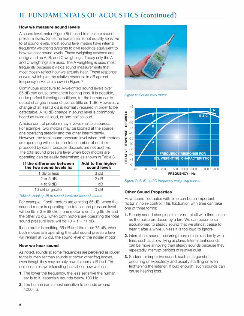
A sound level meter (Figure 6) is used to measure sound pressure levels. Since the human ear is not equally sensitive to all sound levels, most sound level meters have internal frequency weighting systems to give readings equivalent to how we hear sound levels. These weighting systems are designated as A, B, and C weightings. Today only the A and C weightings are used. The A weighting is used most frequently because it yields sound measurements that most closely refl ect how we actually hear. These response curves, which plot the relative response in dB against frequency in Hz, are shown in Figure 7.
Continuous exposure to A-weighted sound levels over 85 dB can cause permanent hearing loss. It is possible, under perfect listening conditions, for the human ear to detect changes in sound level as little as 1 dB. However, a change of at least 3 dB is normally required in order to be detectable. A 10 dB change in sound level is commonly heard as twice as loud, or one-half as loud.
A noise control problem may involve multiple sources. For example, two motors may be located at the source, one operating steadily and the other intermittently. However, the total sound pressure level when both motors are operating will not be the total number of decibels produced by each, because decibels are not additive. The total sound pressure level when both motors are operating can be easily determined as shown in Table 3.
For example: If both motors are emitting 65 dB, when the second motor is operating the total sound pressure level will be 65 + 3 = 68 dB. If one motor is emitting 65 dB and the other 70 dB, when both motors are operating the total sound pressure level will be 70 + 1 = 71 dB.
If one motor is emitting 65 dB and the other 75 dB, when both motors are operating the total sound pressure level will remain at 75 dB, the sound level of the noisier motor.
How we hear sound
As noted, sounds at some frequencies are perceived as louder to the human ear than sounds at certain other frequencies, even though they may actually have the same dB level. This demonstrates two interesting facts about how we hear:
1. The lower the frequency, the less sensitive the human ear is to it, especially sounds below 100 Hz.
2. The human ear is most sensitive to sounds around 4000 Hz.
Other Sound Properties
How sound fl uctuates with time can be an important factor in noise control. This fl uctuation with time can take one of three forms:
1. Steady sound changing little or not at all with time, such as the noise produced by a fan. We can become so accustomed to steady sound that we almost cease to hear it after a while, unless it is too loud to ignore.
2. Intermittent sound, occurring more or less randomly with time, such as a low fl ying airplane. Intermittent sounds can be more annoying than steady sounds because they repeatedly interrupt periods of relative quiet.
3. Sudden or impulsive sound, such as a gunshot, occurring unexpectedly and usually startling or even frightening the listener. If loud enough, such sounds can cause hearing loss.
+5
0
-5
-10
-15
-20
-25
-30
-35
-40
-45
-5020 50 100 200 500 1000 2000 5000 10,000
RE
LAT
IVE
RE
SP
ON
SE
- D
EC
IBE
LS
FREQUENCY - Hz
FREQUENCY RESPONSE FOR
U.S. WEIGHTING CHARACTERISTICS
C
B
A
B & C
A
II. FUNDAMENTALS OF ACOUSTICS (continued)
Figure 6: Sound level meter
Figure 7: A, B, and C frequency weighting curves
If the difference between the two sound levels is:
Add to the higher sound level:
1 dB or less 3 dB2 or 3 dB 2 dB4 to 9 dB 1 dB
10 dB or greater 0 dB
Table 3: Adding dB to sound levels for second source
7
Propagation
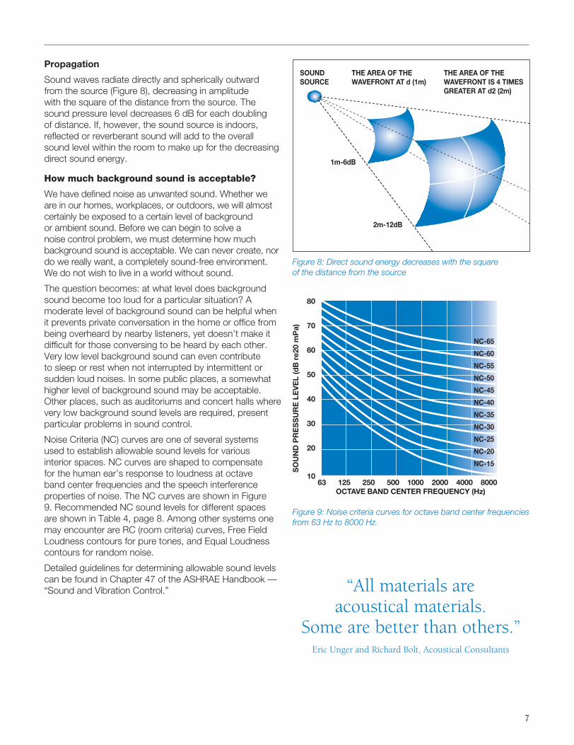
Sound waves radiate directly and spherically outward from the source (Figure 8), decreasing in amplitude with the square of the distance from the source. The sound pressure level decreases 6 dB for each doubling of distance. If, however, the sound source is indoors, refl ected or reverberant sound will add to the overall sound level within the room to make up for the decreasing direct sound energy.
How much background sound is acceptable?
We have defi ned noise as unwanted sound. Whether we are in our homes, workplaces, or outdoors, we will almost certainly be exposed to a certain level of background or ambient sound. Before we can begin to solve a noise control problem, we must determine how much background sound is acceptable. We can never create, nor do we really want, a completely sound-free environment. We do not wish to live in a world without sound.
The question becomes: at what level does background sound become too loud for a particular situation? A moderate level of background sound can be helpful when it prevents private conversation in the home or offi ce from being overheard by nearby listeners, yet doesn’t make it diffi cult for those conversing to be heard by each other. Very low level background sound can even contribute to sleep or rest when not interrupted by intermittent or sudden loud noises. In some public places, a somewhat higher level of background sound may be acceptable. Other places, such as auditoriums and concert halls where very low background sound levels are required, present particular problems in sound control.
Noise Criteria (NC) curves are one of several systems used to establish allowable sound levels for various interior spaces. NC curves are shaped to compensate for the human ear’s response to loudness at octave band center frequencies and the speech interference properties of noise. The NC curves are shown in Figure 9. Recommended NC sound levels for different spaces are shown in Table 4, page 8. Among other systems one may encounter are RC (room criteria) curves, Free Field Loudness contours for pure tones, and Equal Loudness contours for random noise.
Detailed guidelines for determining allowable sound levels can be found in Chapter 47 of the ASHRAE Handbook — “Sound and Vibration Control.”
1m-6dB
2m-12dB
SOUNDSOURCE
THE AREA OF THE WAVEFRONT AT d (1m)
THE AREA OF THE WAVEFRONT IS 4 TIMES GREATER AT d2 (2m)
80
70
60
50
40
30
20
10 63 125 250 500 1000 2000 4000 8000 OCTAVE BAND CENTER FREQUENCY (Hz)
NC-65
NC-60
NC-55
NC-50
NC-45
NC-40
NC-35
NC-30
NC-25
NC-20
NC-15
SO
UN
D P
RE
SS
UR
E L
EV
EL
(dB
re2
0 m
Pa)
Figure 9: Noise criteria curves for octave band center frequencies from 63 Hz to 8000 Hz.
“All materials are acoustical materials.
Some are better than others.”Eric Unger and Richard Bolt, Acoustical Consultants
Figure 8: Direct sound energy decreases with the square of the distance from the source
8
Sound paths
Sound waves can travel through any media — air, water, wood, masonry, or metal. Depending on the media through which it travels, sound is either airborne or structureborne.
Airborne sound
Airborne sound radiates from a source directly into and travels through the air. The sound of traffi c passing our homes, the sound of music or voices from the next room or offi ce, the noise from low fl ying aircraft — all travel to our ears as airborne sound.
Structureborne sound
Structureborne sound travels through solid materials usually in direct mechanical contact with the sound source, or from an impact on that material. Examples are footsteps or objects falling on the fl oor upstairs, a knock at the door, or vibration from loud speakers on the fl oor. All structureborne sound must eventually become airborne sound in order for us to hear it. We can only feel structureborne sound as vibrations in a material. In most noise control situations, both airborne and structureborne sound must be considered.
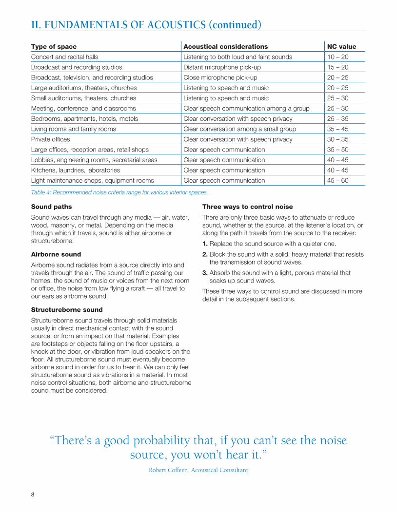
Type of space Acoustical considerations NC value
Concert and recital halls Listening to both loud and faint sounds 10 – 20
Broadcast and recording studios Distant microphone pick-up 15 – 20
Broadcast, television, and recording studios Close microphone pick-up 20 – 25
Large auditoriums, theaters, churches Listening to speech and music 20 – 25
Small auditoriums, theaters, churches Listening to speech and music 25 – 30
Meeting, conference, and classrooms Clear speech communication among a group 25 – 30
Bedrooms, apartments, hotels, motels Clear conversation with speech privacy 25 – 35
Living rooms and family rooms Clear conversation among a small group 35 – 45
Private offi ces Clear conversation with speech privacy 30 – 35
Large offi ces, reception areas, retail shops Clear speech communication 35 – 50
Lobbies, engineering rooms, secretarial areas Clear speech communication 40 – 45
Kitchens, laundries, laboratories Clear speech communication 40 – 45
Light maintenance shops, equipment rooms Clear speech communication 45 – 60
Three ways to control noise
There are only three basic ways to attenuate or reduce sound, whether at the source, at the listener’s location, or along the path it travels from the source to the receiver:
1. Replace the sound source with a quieter one.
2. Block the sound with a solid, heavy material that resists the transmission of sound waves.
3. Absorb the sound with a light, porous material that soaks up sound waves.
These three ways to control sound are discussed in more detail in the subsequent sections.
“There’s a good probability that, if you can’t see the noise source, you won’t hear it.”
Robert Coffeen, Acoustical Consultant
II. FUNDAMENTALS OF ACOUSTICS (continued)
Table 4: Recommended noise criteria range for various interior spaces.
9
Airborne sound transmission loss
Airborne sound transmission loss is a measure of the degree to which a material or construction can block or reduce transmission of sound from one area to another.
All materials block or attenuate sound energy to a degree — heavy, impervious materials more effectively than light, porous ones. Since today’s building technology depends to a great extent on light, fl exible products like gypsum board and lightweight steel framing, the challenge is to utilize these materials in designing assemblies that provide optimum acoustical performance yet do not greatly increase the weight and mass of the structure.
Measuring sound transmission loss
The degree to which a material or construction is effective at blocking airborne sound is expressed as its sound transmission loss (STL) value. Sound transmission loss values are measured at each one-third octave band frequency from 125 to 4000 Hz and are expressed in dB. STL values are determined and measured in accordance with ASTM Standard E90, Standard Test Method for Laboratory Measurement of Airborne Sound Transmission Loss of Building Partitions and Elements. From the sound transmission loss values, a single number rating called the sound transmission class (STC) is determined using ASTM Standard E413, Classifi cation for Rating Sound Insulation.
The values below are based on a typical A-weighted background noise level of 30 dB and are based on multiples of fi ve. Constructions with STC values within 1 or 2 points of what is required or specifi ed should be considered acceptable as construction and test laboratory variations often exceed 2 or more STC points.
“If it sounds good, it is good.” Ron Moulder, Acoustical Consultant
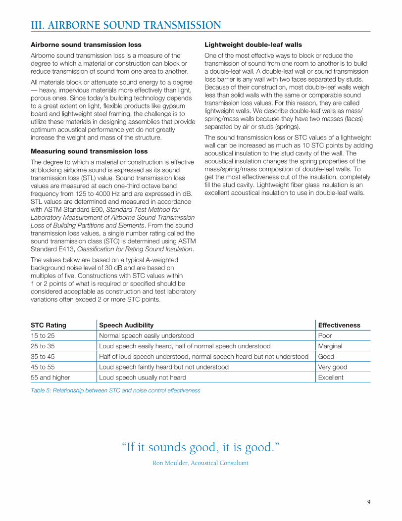
STC Rating Speech Audibility Effectiveness
15 to 25 Normal speech easily understood Poor
25 to 35 Loud speech easily heard, half of normal speech understood Marginal
35 to 45 Half of loud speech understood, normal speech heard but not understood Good
45 to 55 Loud speech faintly heard but not understood Very good
55 and higher Loud speech usually not heard Excellent
III. AIRBORNE SOUND TRANSMISSION
Table 5: Relationship between STC and noise control effectiveness
Lightweight double-leaf walls
One of the most effective ways to block or reduce the transmission of sound from one room to another is to build a double-leaf wall. A double-leaf wall or sound transmission loss barrier is any wall with two faces separated by studs. Because of their construction, most double-leaf walls weigh less than solid walls with the same or comparable sound transmission loss values. For this reason, they are called lightweight walls. We describe double-leaf walls as mass/spring/mass walls because they have two masses (faces) separated by air or studs (springs).
The sound transmission loss or STC values of a lightweight wall can be increased as much as 10 STC points by adding acoustical insulation to the stud cavity of the wall. The acoustical insulation changes the spring properties of the mass/spring/mass composition of double-leaf walls. To get the most effectiveness out of the insulation, completely fi ll the stud cavity. Lightweight fi ber glass insulation is an excellent acoustical insulation to use in double-leaf walls.

10
Sound transmission loss of double-leaf walls
Sound striking a surface such as a wall causes that surface to vibrate, much like the diaphragm of a drum. The more massive the wall, the less the amplitude of vibration of the wall. This results in less noise being transmitted to the room on the other side of the wall. However, except in cases of exterior walls in large commercial buildings, it is rarely practical to rely on sheer mass to reduce the transmission of noise through a wall, especially when attempting to solve noise control problems within the building envelope.
In a conventional double-leaf wall — for example, one constructed of 1/2" gypsum wallboard and 2" x 4" wood studs on 16" centers — vibration is readily transmitted through the structure to the opposite side of the wall where it is heard as noise. The sound reducing property of the air space (the spring) is negated by the wood studs, which form a direct structural connection between the two wall surfaces (the masses). Installing 3-1/2" thick fi ber glass insulation in the stud cavity increases the wall to STC 39 — not suffi cient for uses requiring substantial noise reduction (Figure 10). (Without insulation, the STC rating drops to 35.) Increasing the mass of the insulated wall by adding a layer of gypsum wallboard on each side (Figure 11) raises the STC rating to 46. The increased mass decreases the amplitude of vibration and, therefore, the noise level in the room on the other side of the wall.
Noise transmission through the wall can be greatly reduced by using resilient channels that eliminate direct mechanical connection of the gypsum wallboard to the wood studs (Figure 12). Several resilient channel designs are available. With the resilient channels, the STC rating of the assembly is increased to 57, an acceptable value for most uses.
Double studs (Figure 13) allow doubling of the thickness of the fi ber glass sound absorbing insulation in the wall cavity, as well as further diminishing direct mechanical connections from one wall surface to the other. The STC rating is now 66 — for a noise control effectiveness of “excellent.”
Many other possibilities exist for improving the STC ratings of double-leaf walls. These include the use of light-gauge steel studs that act as a softer spring between the two wall faces and give a much better increase in STC values when acoustical insulation is used in the stud cavity. Steel stud constructions and other wood stud constructions may be found in Section IX of this manual, along with their STC ratings.
III. AIRBORNE SOUND TRANSMISSION (continued)
Figure 10: Conventional wood stud construction, single layer gypsum wallboard each side, 3½" thick fiber glass insulation in wall cavity. STC: 39.
Figure 11: Conventional wood stud construction, double layer gypsum wallboard each side. Increased mass boosts STC rating to 46.
Figure 12: Resilient channels help minimize transmission of vibration through wall. STC rating of 57 considered acceptable for most uses.
Figure 13: Double stud construction permits twice the thickness of fi ber glass sound absorbing insulation. STC rating of 66 is excellent.
11
Insulation density and STC
It is incorrect to assume that higher density insulation within the mass/spring/mass wall system provides better sound transmission loss. Comparative tests conducted at nationally recognized acoustical laboratories have shown that increasing the density of the insulation while maintaining a constant thickness does not have a signifi cant effect on the STC rating of the construction. It is incorrect to assume that heavy insulation in the core of a double leaf wall increases the STC because it adds weight to the wall. To increase the STC of a wall by adding weight, the weight must be added to the faces of the wall, not its core.
For this reason, mineral or rock wool insulation is not better than low-density fi ber glass insulation. These same tests show that insulation thickness within the wall cavity is the most important property, and that complete fi lling of the cavity between wall surfaces provides the best wall performance.
Sound transmission loss and noise control
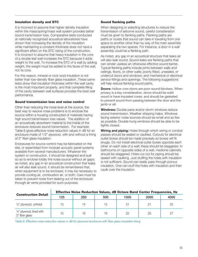
Other than reducing the noise level at the source, the best way to resolve noise problems is to enclose the source within a housing constructed of materials having high sound transmission loss values. The addition of an acoustically absorbent material to the inside of the enclosure reduces sound transmission. For example, Table 6 gives effective noise reduction values in dB for an enclosure made of 1/2" plywood, with and without a lining of 2" fi ber glass insulation.
Enclosures for source control may be fabricated on the site, or assembled from modular acoustic panel systems available from several manufacturers. Whatever the system or construction, it should be designed and built so as to enclose totally the noise source without air gaps; as noted, any gap in an acoustical construction that leaks air will also leak sound. It should be remembered that, when equipment is to be enclosed, it may be necessary to provide cooling air, combustion air, or both. Care must be taken to prevent noise from leaking out of the enclosure through air vents provided for such purposes.
Construction DetailEffective Noise Reduction Values, dB Octave Band Center Frequencies, Hz
125 250 500 1000 2000 4000
½" plywood, unlined 13 14 15 21 21 25
½" plywood, lined with 2" fi ber glass
15 16 19 22 25 27
Sound fl anking paths
When designing or selecting structures to reduce the transmission of airborne sound, careful consideration must be given to fl anking paths. Flanking paths are paths or routes that sound can take in traveling from one space to another other than by way of the main assembly separating the two spaces. For instance, a door in a wall assembly could be a fl anking path.
As noted, any gap in an acoustical structure that leaks air will also leak sound. Sound leaks are fl anking paths that can render useless an otherwise effective sound barrier. Typical fl anking paths include joints between walls and ceilings, fl oors, or other walls; poorly fi tted, unsealed, or undercut doors and windows; and mechanical or electrical service fi ttings and openings. The following suggestions will help reduce fl anking sound paths.
Doors: Hollow core doors are poor sound blockers. When privacy is a key consideration, doors should be solid wood or have insulated cores, and should be gasketed to prevent sound from passing between the door and the jamb or sill.
Windows: Double pane and/or storm windows reduce sound transmission. Weather stripping helps. Windows facing exterior noise sources should be small and as few as possible. Double-hung windows should be able to be tightly closed.
Wiring and piping: Holes through which wiring or conduit passes should be sealed or caulked. Cutouts for electrical outlet boxes should be made precisely so boxes will fi t snugly. Do not install electrical outlet boxes opposite each other on each side of a wall; these should be staggered. In bathrooms on opposite sides of a wall, medicine cabinets should be staggered. Holes cut out for piping should be sealed with caulking. Just stuffi ng the holes with insulation is not suffi cient. Sound can easily pass through porous insulation. One can stuff the holes with insulation and then caulk over the insulation.
Table 6: Effective noise reduction values in dB for plywood enclosure with fi ber glass insulation lining
12
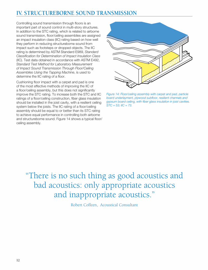
Controlling sound transmission through fl oors is an important part of sound control in multi-story structures. In addition to the STC rating, which is related to airborne sound transmission, fl oor/ceiling assemblies are assigned an impact insulation class (IIC) rating based on how well they perform in reducing structureborne sound from impact such as footsteps or dropped objects. The IIC rating is determined by ASTM Standard E989, Standard Classifi cation for Determination of Impact Insulation Class (IIC). Test data obtained in accordance with ASTM E492, Standard Test Method for Laboratory Measurement of Impact Sound Transmission Through Floor/Ceiling Assemblies Using the Tapping Machine, is used to determine the IIC rating of a fl oor.
Cushioning fl oor impact with a carpet and pad is one of the most effective methods of improving the IIC of a fl oor/ceiling assembly, but this does not signifi cantly improve the STC rating. To increase both the STC and IIC ratings of a fl oor/ceiling construction, fi ber glass insulation should be installed in the joist cavity, with a resilient ceiling system below the joists. The IIC rating of a fl oor/ceiling assembly should be equal to or better than its STC rating to achieve equal performance in controlling both airborne and structureborne sound. Figure 14 shows a typical fl oor/ceiling assembly.
Figure 14: Floor/ceiling assembly with carpet and pad, particle board underlayment, plywood subfl oor, resilient channels and gypsum board ceiling, with fi ber glass insulation in joist cavities. STC = 53; IIC = 73.
“There is no such thing as good acoustics and bad acoustics: only appropriate acoustics
and inappropriate acoustics.” Robert Coffeen, Acoustical Consultant
IV. STRUCTUREBORNE SOUND TRANSMISSION
13
Defi nitions
We have defi ned sound as a form of energy. Sound absorption is the ability of a material to transform acoustical energy into some other form of energy, usually heat. All materials absorb some acoustical energy. Some materials, such as gypsum board, absorb it poorly, refl ecting most of the energy that strikes their surfaces, while other materials, such as fi ber glass insulation, absorb most of it.
Measuring sound absorption: The decimal fraction of the sound energy absorbed and not refl ected by a material is termed its sound absorption coeffi cient. As materials absorb different amounts of sound energy at different frequencies, sound absorption coeffi cients are measured at one-third octave band center frequencies from 125 to 4000 Hz.
Building materials are generally rated by their noise reduction coeffi cient (NRC). This single number rating is the average of the sound absorption coeffi cients of a material at 250, 500, 1000, and 2000 Hz, rounded to the nearest .05. Sound absorption coeffi cients and single number rating values are determined using ASTM Standard C423, Standard Test Method for Sound Absorption and Sound Absorption Coeffi cients by the Reverberation Room Method. A material is usually considered to be a sound absorber if it has an NRC value greater than 0.35.
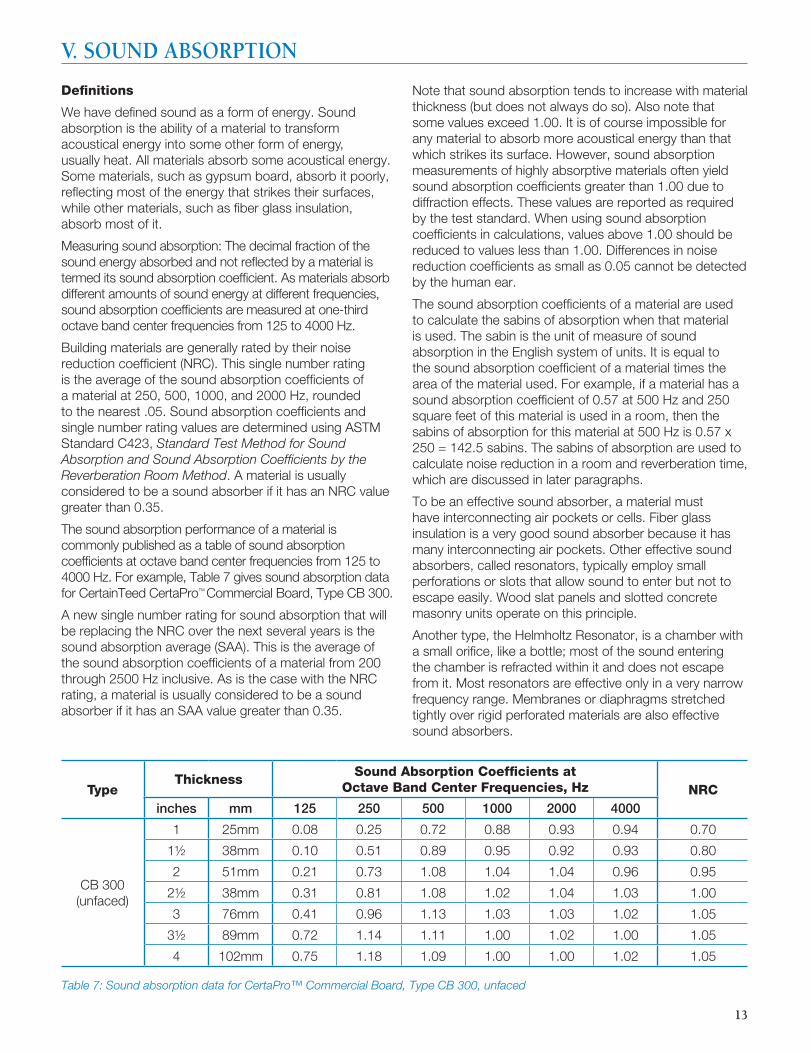
The sound absorption performance of a material is commonly published as a table of sound absorption coeffi cients at octave band center frequencies from 125 to 4000 Hz. For example, Table 7 gives sound absorption data for CertainTeed CertaPro™ Commercial Board, Type CB 300.
A new single number rating for sound absorption that will be replacing the NRC over the next several years is the sound absorption average (SAA). This is the average of the sound absorption coeffi cients of a material from 200 through 2500 Hz inclusive. As is the case with the NRC rating, a material is usually considered to be a sound absorber if it has an SAA value greater than 0.35.
Note that sound absorption tends to increase with material thickness (but does not always do so). Also note that some values exceed 1.00. It is of course impossible for any material to absorb more acoustical energy than that which strikes its surface. However, sound absorption measurements of highly absorptive materials often yield sound absorption coeffi cients greater than 1.00 due to diffraction effects. These values are reported as required by the test standard. When using sound absorption coeffi cients in calculations, values above 1.00 should be reduced to values less than 1.00. Differences in noise reduction coeffi cients as small as 0.05 cannot be detected by the human ear.
The sound absorption coeffi cients of a material are used to calculate the sabins of absorption when that material is used. The sabin is the unit of measure of sound absorption in the English system of units. It is equal to the sound absorption coeffi cient of a material times the area of the material used. For example, if a material has a sound absorption coeffi cient of 0.57 at 500 Hz and 250 square feet of this material is used in a room, then the sabins of absorption for this material at 500 Hz is 0.57 x 250 = 142.5 sabins. The sabins of absorption are used to calculate noise reduction in a room and reverberation time, which are discussed in later paragraphs.
To be an effective sound absorber, a material must have interconnecting air pockets or cells. Fiber glass insulation is a very good sound absorber because it has many interconnecting air pockets. Other effective sound absorbers, called resonators, typically employ small perforations or slots that allow sound to enter but not to escape easily. Wood slat panels and slotted concrete masonry units operate on this principle.
Another type, the Helmholtz Resonator, is a chamber with a small orifi ce, like a bottle; most of the sound entering the chamber is refracted within it and does not escape from it. Most resonators are effective only in a very narrow frequency range. Membranes or diaphragms stretched tightly over rigid perforated materials are also effective sound absorbers.
Type Thickness
Sound Absorption Coeffi cients at Octave Band Center Frequencies, Hz NRC
inches mm 125 250 500 1000 2000 4000
CB 300(unfaced)
1 25mm 0.08 0.25 0.72 0.88 0.93 0.94 0.70
1½ 38mm 0.10 0.51 0.89 0.95 0.92 0.93 0.80
2 51mm 0.21 0.73 1.08 1.04 1.04 0.96 0.95
2½ 38mm 0.31 0.81 1.08 1.02 1.04 1.03 1.00
3 76mm 0.41 0.96 1.13 1.03 1.03 1.02 1.05
3½ 89mm 0.72 1.14 1.11 1.00 1.02 1.00 1.05
4 102mm 0.75 1.18 1.09 1.00 1.00 1.02 1.05
Table 7: Sound absorption data for CertaPro™ Commercial Board, Type CB 300, unfaced
V. SOUND ABSORPTION
14
Sound absorption and noise control
Sound absorption is used to control or reduce sound within a room, unlike sound transmission loss — which is used to describe the transmission of sound from one room to another. In addition to reducing the sound level in a room, the addition of sound absorption in a room can also reduce the room’s reverberation time. This is the time in seconds that it takes for a sound to decay or decrease 60 dB in level. For good speech intelligibility, the reverberation time in a room should be less than 1.0 seconds.
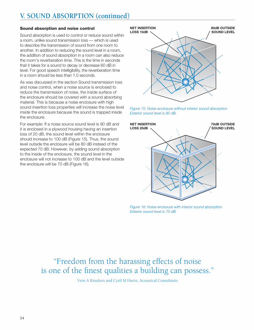
As was discussed in the section Sound transmission loss and noise control, when a noise source is enclosed to reduce the transmission of noise, the inside surface of the enclosure should be covered with a sound absorbing material. This is because a noise enclosure with high sound insertion loss properties will increase the noise level inside the enclosure because the sound is trapped inside the enclosure.
For example: If a noise source sound level is 90 dB and it is enclosed in a plywood housing having an insertion loss of 20 dB, the sound level within the enclosure should increase to 100 dB (Figure 15). Thus, the sound level outside the enclosure will be 80 dB instead of the expected 70 dB. However, by adding sound absorption to the inside of the enclosure, the sound level in the enclosure will not increase to 100 dB and the level outside the enclosure will be 70 dB (Figure 16).
“Freedom from the harassing effects of noise is one of the fi nest qualities a building can possess.”
Vern A Knudsen and Cyril M Harris, Acoustical Consultants
NET INSERTION LOSS 10dB
80dB OUTSIDE SOUND LEVEL
NET INSERTION LOSS 20dB
70dB OUTSIDE SOUND LEVEL
V. SOUND ABSORPTION (continued)
Figure 15: Noise enclosure without interior sound absorption. Exterior sound level is 80 dB.
Figure 16: Noise enclosure with interior sound absorption. Exterior sound level is 70 dB.
15
Sound level reduction calculation
This same principle can be used simply to reduce the sound level in a room. There is a simple relation between the reduction in sound level in a room and the amount of sound absorption added to the room. This relationship can be expressed in the following equation:
Reduction in sound level = 10 log AA/A
B dB
Where: AA = sound absorption in sabins in the room after
treatment, AB = sound absorption in sabins in the room
before treatment
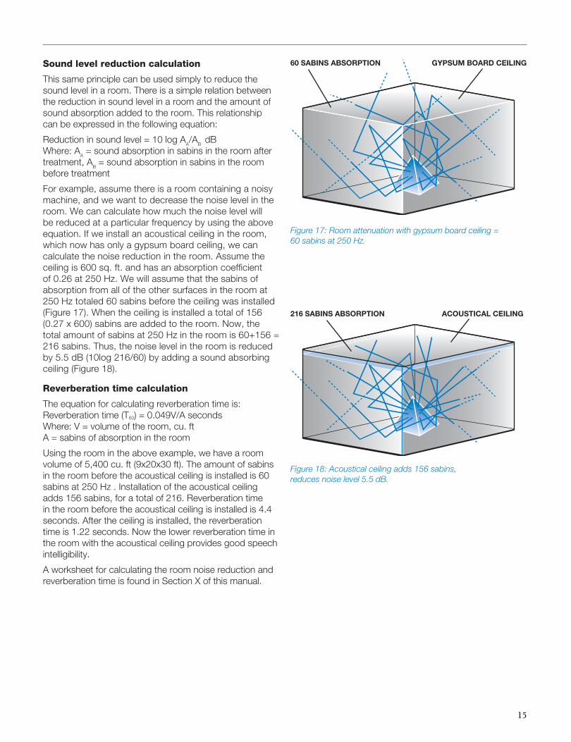
For example, assume there is a room containing a noisy machine, and we want to decrease the noise level in the room. We can calculate how much the noise level will be reduced at a particular frequency by using the above equation. If we install an acoustical ceiling in the room, which now has only a gypsum board ceiling, we can calculate the noise reduction in the room. Assume the ceiling is 600 sq. ft. and has an absorption coeffi cient of 0.26 at 250 Hz. We will assume that the sabins of absorption from all of the other surfaces in the room at 250 Hz totaled 60 sabins before the ceiling was installed (Figure 17). When the ceiling is installed a total of 156 (0.27 x 600) sabins are added to the room. Now, the total amount of sabins at 250 Hz in the room is 60+156 = 216 sabins. Thus, the noise level in the room is reduced by 5.5 dB (10log 216/60) by adding a sound absorbing ceiling (Figure 18).
Reverberation time calculation
The equation for calculating reverberation time is:Reverberation time (T60) = 0.049V/A secondsWhere: V = volume of the room, cu. ftA = sabins of absorption in the room
Using the room in the above example, we have a room volume of 5,400 cu. ft (9x20x30 ft). The amount of sabins in the room before the acoustical ceiling is installed is 60 sabins at 250 Hz . Installation of the acoustical ceiling adds 156 sabins, for a total of 216. Reverberation time in the room before the acoustical ceiling is installed is 4.4 seconds. After the ceiling is installed, the reverberation time is 1.22 seconds. Now the lower reverberation time in the room with the acoustical ceiling provides good speech intelligibility.
A worksheet for calculating the room noise reduction and reverberation time is found in Section X of this manual.
60 SABINS ABSORPTION GYPSUM BOARD CEILING
216 SABINS ABSORPTION ACOUSTICAL CEILING
Figure 17: Room attenuation with gypsum board ceiling = 60 sabins at 250 Hz.
Figure 18: Acoustical ceiling adds 156 sabins, reduces noise level 5.5 dB.
16
We have shown that sound travels from the source, along a path, to the listener, or receiver. Hence the term SPR — source, path, receiver noise control. Control of noise thus involves three considerations: Acoustical treatment at the source of noise; acoustical treatment of the path it travels — everything between the source and the receiver; and acoustical treatment at the receiver — where the listener is.
The solution to a specifi c noise control situation often involves considering the problem from one, two, or all three of these factors. However, it is almost always best to start at the source. That’s where the most effective solutions to noise control are likely to be easily achieved at the lowest cost.
Controlling noise at the source
Before designing acoustical treatment to attenuate noise at the source, consider the following measures:
1. Moving the source to a more distant location or to another area, where its noise will not reach an objectionable level at the listener’s place.
2. Adjusting or modifying the source for quieter operation. If for example the source of noise is a mechanism such as a fan or motor, it may be operated at a lower speed.
3. Repairing or servicing the noise source. It may be as simple a matter as lubricating gears, tensioning drive belts, or tightening loose and vibrating screws or bolts.
4. Mounting the noise source on a resilient base (such as springs or soft pads) to isolate vibration and thus reduce the structureborne sound arriving at the listener’s location.
5. Replacing the noise source with a quieter one. Modern appliances, for example, generally operate much more quietly than older models.
If these measures are not practical or, if attempted, fail to yield satisfactory results, the noise source should be enclosed within a housing having high sound transmission loss properties. Depending on the size of the noise source, such a housing might be constructed of plywood, gypsum board, sheet metal, or fi ber glass-reinforced plastic.
We have shown that, if an enclosure with a high sound transmission loss value is lined with a material having a high sound absorption value, the overall sound transmission loss value will be increased and the overall noise reduction improved.
Obviously, if the noise source is outdoors — in the form of traffi c noise, aircraft, power lawn mower, or any other source over which we have no control — we cannot move, adjust, repair, service, or replace it. All we can do in that case is try to reduce the noise along its path or at the receiver by building or retrofi tting high sound transmission loss into the exterior walls and roofs of our homes, offi ces, and public buildings to attenuate these outside noises. It should be emphasized that it is far less costly to design noise control into a structure at the beginning than to retrofi t after the building is built.
Controlling noise along its path
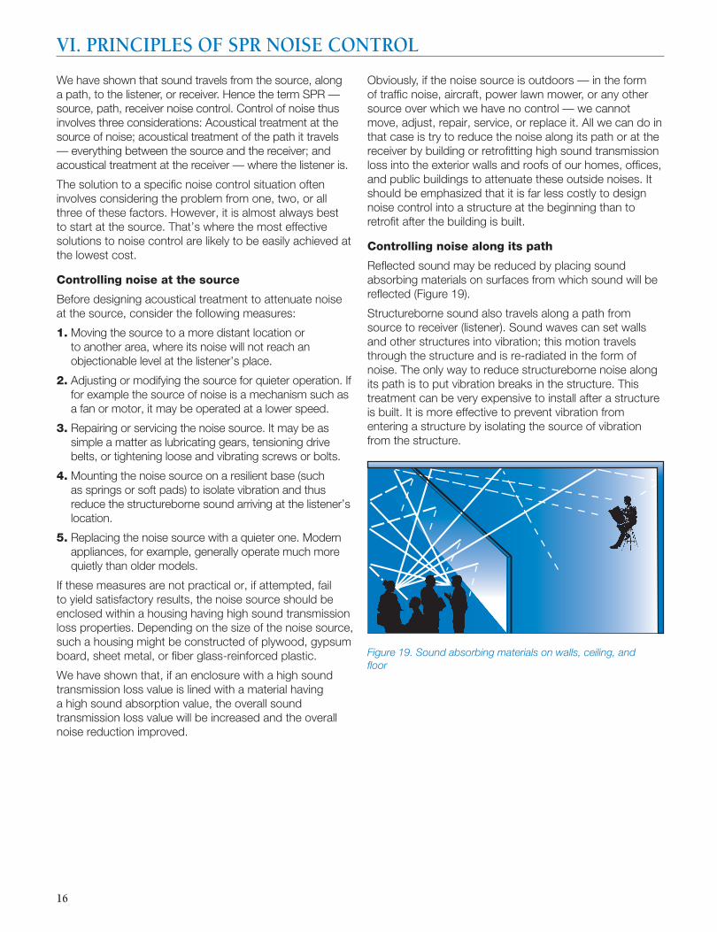
Refl ected sound may be reduced by placing sound absorbing materials on surfaces from which sound will be refl ected (Figure 19).
Structureborne sound also travels along a path from source to receiver (listener). Sound waves can set walls and other structures into vibration; this motion travels through the structure and is re-radiated in the form of noise. The only way to reduce structureborne noise along its path is to put vibration breaks in the structure. This treatment can be very expensive to install after a structure is built. It is more effective to prevent vibration from entering a structure by isolating the source of vibration from the structure.
VI. PRINCIPLES OF SPR NOISE CONTROL
Figure 19. Sound absorbing materials on walls, ceiling, and fl oor
17
Controlling noise at the receiver
As noted, the fi rst and most practical location for successful noise control is at the source. Other practical solutions to noise control are often those involving treatment of the path, which usually involves multiple components — direct, refl ected, and fl anking. If source control is not practical, another approach would be to treat the problem at the receiver.
“Temporary” sound control
Direct ear protection (earplugs or earmuffs) is often used to protect workers’ hearing when source and path noise control are not practical or possible. However, such measures are considered by the U. S. Occupational Safety and Health Administration to be “temporary”; in most instances, OSHA mandates “permanent” noise reduction measures. There is only one way to provide “permanent” receiver noise control, and that is to enclose the listener in an acoustically effective enclosure or room.
The general principles of noise control at the source apply to noise control at the receiver. However, there are additional concerns involved including such features as doors, windows, ventilation, and lighting. All of these features will be required in an acoustically effective workplace, and all present their own sets of noise control problems.
Three steps to noise control solutions
1. Locate the source of noiseThe fi rst step in noise control is to investigate the real noise source. It has been mentioned that noise control problems may involve merely moving the source farther from the receiver, adjusting or repairing the source if it is a piece of noisy equipment, or replacing it. If none of these work, an acoustically effi cient enclosure will have to be designed. Once the true source has been identifi ed, the next step is to measure the noise.
2. Measure the noiseA sound level meter is used to measure the noise level at several locations — at its source, along its path, and at the receiver or listener’s location — using the A-weighted scale and also measuring the sound level in octave or third-octave bands. Sound level meter readings will not only provide sound pressure (loudness) levels at various locations, but will also show which frequencies are most offensive to the listener. This data will be helpful in selecting acoustical materials with sound absorption and/or sound reduction properties best suited to the particular application.
3. Design the solutionOnce the noise source has been located, diagnosed, and measured, the solution can be designed. The fi rst approach to solving the problem should generally focus on source control, either by modifying the noise-producing element itself or by covering it with an acoustical enclosure. If source attenuation is not practical, possible, or suffi cient to lower the sound pressure level at the receiver position, then controlling or reducing the noise at the receiver should be considered. Usually, noise control along the path should be considered only if it is not possible to achieve the required noise reduction by source and receiver treatment.
Solving the noise problem may involve acoustic treatment at more than one location. For example, acoustical enclosure of the noise source plus sound absorbing materials along the noise path may be the most effective and economical way to reduce to an acceptable level the sound pressure at the receiver location.
Designing a solution to the noise problem may involve consideration of acoustical treatments that provide both sound absorption and sound transmission loss properties. For example, a plywood housing enclosing the noise source may provide adequate sound transmission loss performance, but its overall acoustical effectiveness will be improved by lining it with a sound absorbing material such as fi ber glass insulation.
In any case, the services of a professional acoustical consultant will be well worth their fee in terms of time and money saved, false starts avoided, noise problems solved, and productivity and comfort restored.
“The dollar cost of noise... is vague... although certainly real enough. But the loss in real estate values is plain for
all to see.”R. A. Baron, The Tyranny of Noise
18
If not acoustically treated, noise from heating, ventilating, and air-conditioning equipment can travel from room to room in the home or in the offi ce. Noise produced by fans and motors of central air equipment can be transmitted throughout the duct system. High air velocities in the duct system can cause noise-producing turbulence. Also, turning vanes, dampers, and other elements inside the ducts, grilles, and diffusers can whistle or rattle. HVAC ductwork can also act as a “speaking tube,” carrying conversations from one room or offi ce into other spaces.
Noise from central equipment: When operating heating and air-conditioning equipment, a good guideline is “lower and slower”: lower volumes of air moved through the system with fans and blowers operating at a slower speed. Central air equipment should also be acoustically isolated from spaces where airborne noise would be objectionable. Equipment should be mounted on vibration isolators to avoid transmission of structureborne noise. Sound traps or baffl es will help to attenuate equipment noise in adjacent ductwork.
Noise in air duct systems: Heating, ventilating, and air-conditioning ductwork can be a source of noise as well as a transmitter of it. Sheet metal ductwork without insulation can produce popping and banging noises due to expansion and contraction caused by changes in air temperature. Components within the duct system, abrupt changes in direction, and restrictions in the system can produce turbulence and air rush noise.
Most of these noise problems can be solved with fi ber glass duct insulation in either of two forms:
1. Fiber glass duct liner, designed for installation inside sheet metal ductwork to attenuate air rush and central equipment noise as well as to control heat loss or gain through duct walls.
2. Fiber glass duct board, combining acoustical/thermal insulation with a reinforced foil-kraft air barrier/vapor retarder, from which complete air duct systems may be fabricated.
Octave Band Center Frequencies, Hz
125 250 500 1000 2000 4000
Uninsulated sheet metal ducts 0.1 0.1 0.1 0.1 0.1 0.1
Sheet metal ducts with 1" duct liner 0.3 0.7 1.9 5.3 4.8 2.3
Fiber glass duct board, 1" thick 0.4 1.4 3.3 3.9 5.0 3.7
Fiber glass ducts wraps, used as thermal insulation on exteriors of sheet metal ducts, provide little acoustical benefi t except by muffl ing the popping and banging noises when ducts undergo temperature changes.
Table 8, comparing sound attenuation in dB per lineal foot of uninsulated sheet metal, sheet metal lined with fi ber glass duct liner, and fi ber glass duct board, shows signifi cant perceived noise reduction obtainable with fi ber glass duct liner or duct board. Note: Individual products are often compared by their NRC values; however, differences of up to 0.1 in the NRC values published by their manufacturers have an insignifi cant effect on the sound attenuation in the installed duct.
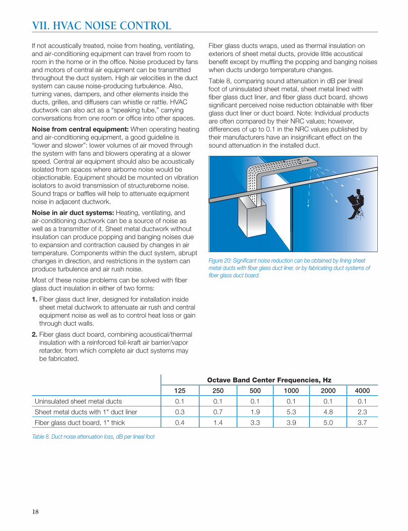
Figure 20: Signifi cant noise reduction can be obtained by lining sheet metal ducts with fi ber glass duct liner, or by fabricating duct systems of fi ber glass duct board.
Table 8. Duct noise attenuation loss, dB per lineal foot
VII. HVAC NOISE CONTROL

19
In addition to the specifi c sound rated construction assemblies detailed in this guide, certain construction practices are recommended to reduce sound transmission.
To obtain maximum benefi t with sound rated constructions, the perimeter of the construction must be sealed with caulking wherever it is not completely sealed by normal construction methods (e.g., tape and joint compound). In general, penetrations such as service lines (e.g., plumbing and gas lines), electrical outlets, and medicine cabinets should be minimized. If penetrations are necessary, openings should be caulked airtight; they can also be fi lled with Handi-Fill™, a multi-purpose fiber glass roll that is conveniently sized for small areas. If medicine cabinets are installed, they should be surface mounted, and if electrical boxes are to be included on each side of the partition, they should not be installed “back-to back” within the same stud space.
Plumbing noise can be reduced by using larger pipes or cast-iron pipes, installing air chambers to eliminate water hammer, and by isolating pipes from structural framing with resilient rods. Doors of solid wood or mineral core provide better sound control than hollow core doors. Door frames and sills should be gasketed to seal tightly when doors are closed. Windows should have weatherstripping and double panes of insulating glass. The use of heavy curtains or draperies can help reduce sound transmission.
As with partition and wall construction, penetrations in sound rated fl oor/ceiling assemblies should be caulked airtight. Ceiling fi xtures should be surface mounted, not recessed, and carpet and pad or resilient tile will greatly reduce impact sound transmission through these assemblies.
The right insulation material
CertainTeed offers a complete line of insulation products made of one of the most dependable, durable, and effective materials — fi ber glass. In addition to its thermal properties, fi ber glass is also an excellent acoustical material.
CertaPro® AcoustaTherm™ Batts, NoiseReducer™ Sound Control Batts and Acoustical Ceiling Batts can help to effectively control sound in walls and ceilings. InsulSafe® SP and OPTIMA® blowing insulations — which are approved for use in the Blow-In-Blanket® System (BIBS) — also provide excellent acoustical performance, as does CertainTeed Sustainable Insulation™, which is made with signifi cant renewable and recycled content and an organic plant-based binder that contains no added formaldehyde, acrylics or dyes. The illustrations that start on page 23 are representative of the more common applications of fi ber glass insulation for acoustical purposes.
CertainTeed CertaSpray® open and closed cell foam insulation provides enhanced thermal performance in walls and ceilings, and also seals leaks in the building envelope. Sealing such leaks contributes to improved acoustics by closing pathways through which outside noise can enter a structure.
In addition to the previously mentioned products, CertainTeed offers other products that can be used for sound control. CertainTeed ToughGard® T and ToughGard® R Fiber Glass Duct Liner, ToughGard® Duct Board, SoftTouch™ Duct Wrap and CertainTeed Commercial Board are also widely used for sound control.
VIII. RESIDENTIAL SOUND CONTROL PRACTICES
20
1. Thinking you don’t have a noise problem
In a factory you have a noise problem if a person is exposed to a noise level greater than an A-weighted level of 85 dB. Ear protectors should only be considered a temporary solution to such a noise problem. Even lower levels could be a problem, such as a 55 dB level in a classroom. In general, if communications is diffi cult in a noisy area, you have a noise problem.
2. Not considering noise control before a project is started
Although a source of noise can be treated after installation, it’s generally twice as expensive and half as effective compared with designing proper noise control into the system before the noise source is installed.
3. Not conducting a detailed study of noisy equipment
Most noisy equipment has several noise sources, all of which must be considered. When analyzing noise sources, the spectrum of the noise from the equipment needs to be studied. At minimum, octave band noise levels from the equipment should be obtained. You cannot solve a noise problem by knowing only the overall noise level generated by the equipment.
4. Not using a systems approach to noise control
A common waste of noise control dollars is the failure to consider all possible solutions and noise paths. To treat one noise source and not consider all possible noise sources could lead to unacceptable noise levels when a project is completed. The same is true if only one path of noise transmission is considered. All airborne and structureborne noise paths must be studied.
5. Not sealing air leaks
Sound always takes the easiest path around or through a barrier. Construction gaps or air leaks are by far the easiest way for sound to pass from one space to another.
“In many instances it is no more expensive to design a machine to operate quietly than it is to design it to be noisy.”
George Diehl, retired Acoustical Engineer
VIII. RESIDENTIAL SOUND CONTROL PRACTICES (continued)
Five noise control mistakes to avoid
21
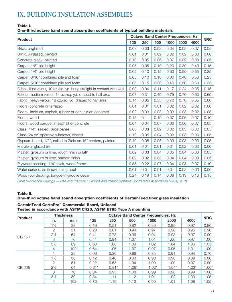
Table I. One-third octave band sound absorption coeffi cients of typical building materials
Product Octave Band Center Frequencies, Hz
NRC125 250 500 1000 2000 4000
Brick, unglazed 0.03 0.03 0.03 0.04 0.05 0.07 0.05
Brick, unglazed, painted 0.01 0.01 0.02 0.02 0.02 0.03 0.00
Concrete block, painted 0.10 0.05 0.06 0.07 0.09 0.08 0.05
Carpet, 1/8" pile height 0.05 0.05 0.10 0.20 0.30 0.40 0.15
Carpet, 1/4" pile height 0.05 0.10 0.15 0.30 0.50 0.55 0.25
Carpet, 3/16" combined pile and foam 0.05 0.10 0.10 0.30 0.40 0.50 0.25
Carpet, 5/16" combined pile and foam 0.05 0.15 0.30 0.40 0.50 0.60 0.35
Fabric, light velour, 10 oz./sq. yd. hung straight in contact with wall 0.03 0.04 0.11 0.17 0.24 0.35 0.15
Fabric, medium velour, 14 oz./sq. yd. draped to half area 0.07 0.31 0.49 0.75 0.70 0.60 0.55
Fabric, heavy velour, 18 oz./sq. yd. draped to half area 0.14 0.35 0.55 0.72 0.70 0.65 0.60
Floors, concrete or terrazzo 0.01 0.01 0.01 0.02 0.02 0.02 0.00
Floors, linoleum, asphalt, rubber or cork tile on concrete 0.02 0.03 0.03 0.03 0.03 0.02 0.05
Floors, wood 0.15 0.11 0.10 0.07 0.06 0.07 0.10
Floors, wood parquet in asphalt or concrete 0.04 0.04 0.07 0.06 0.06 0.07 0.05
Glass, 1/4", sealed, large panes 0.05 0.03 0.02 0.02 0.03 0.02 0.05
Glass, 24 oz. operable windows, closed 0.10 0.05 0.04 0.03 0.03 0.03 0.05
Gypsum board, 1/2", nailed to 2x4s on 16" centers, painted 0.10 0.08 0.05 0.03 0.03 0.03 0.05
Marble or glazed tile 0.01 0.01 0.01 0.01 0.02 0.02 0.00
Plaster, gypsum or lime, rough fi nish or lath 0.02 0.03 0.04 0.05 0.04 0.03 0.05
Plaster, gypsum or lime, smooth fi nish 0.02 0.02 0.03 0.04 0.04 0.03 0.05
Plywood paneling, 1/4" thick, wood frame 0.58 0.22 0.07 0.04 0.03 0.07 0.10
Water surface, as in swimming pool 0.01 0.01 0.01 0.01 0.02 0.03 0.00
Wood roof decking, tongue-in-groove cedar 0.24 0.19 0.14 0.08 0.13 0.10 0.15From “Acoustical Ceilings — Use and Practice,” Ceilings and Interior Systems Contractors Association (1984). p.18.
IX. BUILDING INSULATION ASSEMBLIES
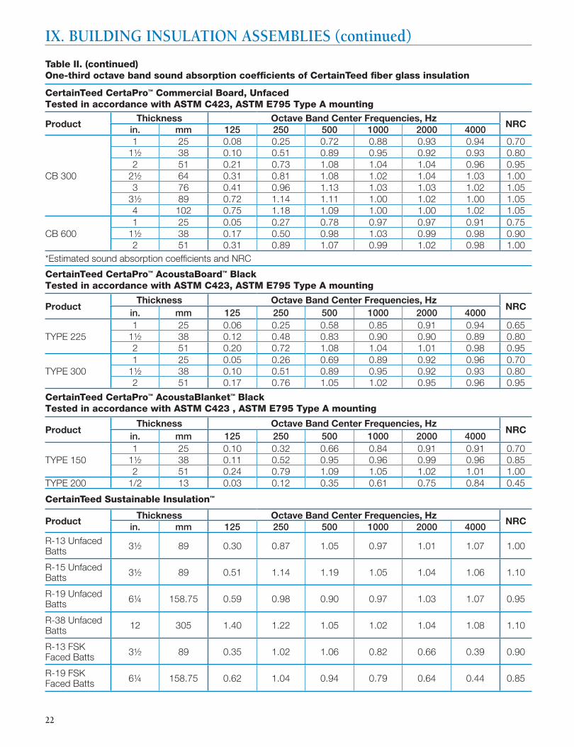
Table II. One-third octave band sound absorption coeffi cients of CertainTeed fi ber glass insulation
CertainTeed CertaPro™ Commercial Board, UnfacedTested in accordance with ASTM C423, ASTM E795 Type A mounting
Product Thickness Octave Band Center Frequencies, Hz
NRCin. mm 125 250 500 1000 2000 4000
CB 150
1½ 38 0.19 0.51 0.82 0.86 0.95 0.97 0.802 51 0.23 0.61 0.94 0.97 0.98 0.96 0.90
2½ 64 0.41 0.78 0.96 0.94 0.93 0.97 0.903 76 0.41 0.94 1.07 1.01 1.00 0.97 1.00
3½ 89 0.60 1.08 1.09 1.02 1.04 1.06 1.054 102 0.64 1.05 1.07 0.97 0.96 1.01 1.00
CB 225
1 25 0.06 0.30 0.68 0.85 0.91 0.94 0.701½ 38 0.12 0.48 0.83 0.90 0.90 0.89 0.802 51 0.22 0.63 1.04 1.00 1.00 0.97 0.90
2½ 64 0.31* 0.81* 1.08* 1.02* 1.04* 1.03* 1.00*3 76 0.34 0.95 1.08 0.99 0.98 0.99 1.00
3½ 89 0.54 1.11 1.12 1.01 1.02 1.00 1.054 102 0.70 1.15 1.12 0.99 1.01 1.08 1.05
22
IX. BUILDING INSULATION ASSEMBLIES (continued)
Table II. (continued) One-third octave band sound absorption coeffi cients of CertainTeed fi ber glass insulation
CertainTeed CertaPro™ Commercial Board, UnfacedTested in accordance with ASTM C423, ASTM E795 Type A mounting
Product Thickness Octave Band Center Frequencies, Hz
NRCin. mm 125 250 500 1000 2000 4000
CB 300
1 25 0.08 0.25 0.72 0.88 0.93 0.94 0.701½ 38 0.10 0.51 0.89 0.95 0.92 0.93 0.802 51 0.21 0.73 1.08 1.04 1.04 0.96 0.95
2½ 64 0.31 0.81 1.08 1.02 1.04 1.03 1.003 76 0.41 0.96 1.13 1.03 1.03 1.02 1.05
3½ 89 0.72 1.14 1.11 1.00 1.02 1.00 1.05 4 102 0.75 1.18 1.09 1.00 1.00 1.02 1.05
CB 600 1 25 0.05 0.27 0.78 0.97 0.97 0.91 0.75
1½ 38 0.17 0.50 0.98 1.03 0.99 0.98 0.902 51 0.31 0.89 1.07 0.99 1.02 0.98 1.00
*Estimated sound absorption coeffi cients and NRC
CertainTeed CertaPro™ AcoustaBoard™ BlackTested in accordance with ASTM C423, ASTM E795 Type A mounting
Product Thickness Octave Band Center Frequencies, Hz
NRCin. mm 125 250 500 1000 2000 4000
TYPE 225 1 25 0.06 0.25 0.58 0.85 0.91 0.94 0.65
1½ 38 0.12 0.48 0.83 0.90 0.90 0.89 0.802 51 0.20 0.72 1.08 1.04 1.01 0.98 0.95
TYPE 3001 25 0.05 0.26 0.69 0.89 0.92 0.96 0.70
1½ 38 0.10 0.51 0.89 0.95 0.92 0.93 0.802 51 0.17 0.76 1.05 1.02 0.95 0.96 0.95
CertainTeed CertaPro™ AcoustaBlanket™ BlackTested in accordance with ASTM C423 , ASTM E795 Type A mounting
Product Thickness Octave Band Center Frequencies, Hz
NRCin. mm 125 250 500 1000 2000 4000
TYPE 1501 25 0.10 0.32 0.66 0.84 0.91 0.91 0.70
1½ 38 0.11 0.52 0.95 0.96 0.99 0.96 0.85 2 51 0.24 0.79 1.09 1.05 1.02 1.01 1.00
TYPE 200 1/2 13 0.03 0.12 0.35 0.61 0.75 0.84 0.45
CertainTeed Sustainable Insulation™
Product Thickness Octave Band Center Frequencies, Hz
NRCin. mm 125 250 500 1000 2000 4000
R-13 Unfaced Batts 3½ 89 0.30 0.87 1.05 0.97 1.01 1.07 1.00
R-15 Unfaced Batts 3½ 89 0.51 1.14 1.19 1.05 1.04 1.06 1.10
R-19 Unfaced Batts 6¼ 158.75 0.59 0.98 0.90 0.97 1.03 1.07 0.95
R-38 Unfaced Batts 12 305 1.40 1.22 1.05 1.02 1.04 1.08 1.10
R-13 FSK Faced Batts 3½ 89 0.35 1.02 1.06 0.82 0.66 0.39 0.90
R-19 FSK Faced Batts 6¼ 158.75 0.62 1.04 0.94 0.79 0.64 0.44 0.85
23
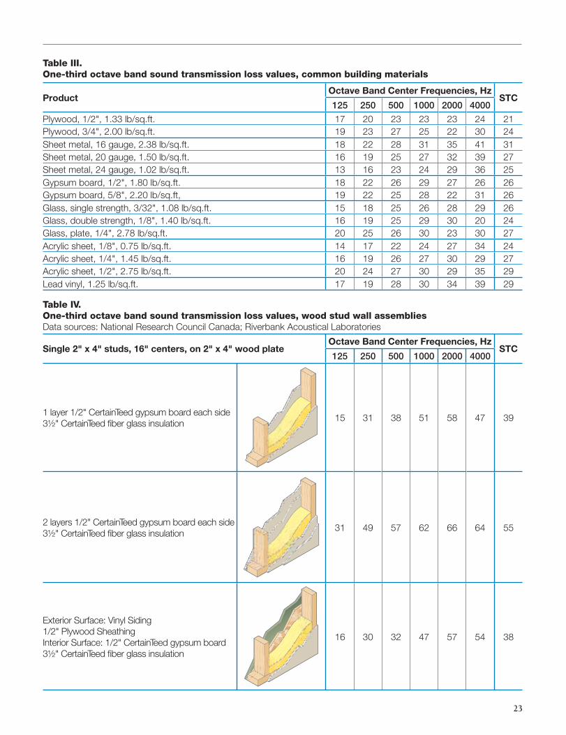
Table III. One-third octave band sound transmission loss values, common building materials
ProductOctave Band Center Frequencies, Hz
STC125 250 500 1000 2000 4000
Plywood, 1/2", 1.33 lb/sq.ft. 17 20 23 23 23 24 21Plywood, 3/4", 2.00 lb/sq.ft. 19 23 27 25 22 30 24Sheet metal, 16 gauge, 2.38 lb/sq.ft. 18 22 28 31 35 41 31Sheet metal, 20 gauge, 1.50 lb/sq.ft. 16 19 25 27 32 39 27Sheet metal, 24 gauge, 1.02 lb/sq.ft. 13 16 23 24 29 36 25Gypsum board, 1/2", 1.80 lb/sq.ft. 18 22 26 29 27 26 26Gypsum board, 5/8", 2.20 lb/sq.ft, 19 22 25 28 22 31 26Glass, single strength, 3/32", 1.08 lb/sq.ft. 15 18 25 26 28 29 26Glass, double strength, 1/8", 1.40 lb/sq.ft. 16 19 25 29 30 20 24Glass, plate, 1/4", 2.78 lb/sq.ft. 20 25 26 30 23 30 27Acrylic sheet, 1/8", 0.75 lb/sq.ft. 14 17 22 24 27 34 24Acrylic sheet, 1/4", 1.45 lb/sq.ft. 16 19 26 27 30 29 27Acrylic sheet, 1/2", 2.75 lb/sq.ft. 20 24 27 30 29 35 29Lead vinyl, 1.25 lb/sq.ft. 17 19 28 30 34 39 29
Table IV. One-third octave band sound transmission loss values, wood stud wall assembliesData sources: National Research Council Canada; Riverbank Acoustical Laboratories
Single 2" x 4" studs, 16" centers, on 2" x 4" wood plateOctave Band Center Frequencies, Hz
STC125 250 500 1000 2000 4000
1 layer 1/2" CertainTeed gypsum board each side3½" CertainTeed fi ber glass insulation
15 31 38 51 58 47 39
2 layers 1/2" CertainTeed gypsum board each side3½" CertainTeed fi ber glass insulation
31 49 57 62 66 64 55
Exterior Surface: Vinyl Siding1/2" Plywood SheathingInterior Surface: 1/2" CertainTeed gypsum board3½" CertainTeed fi ber glass insulation
16 30 32 47 57 54 38
24
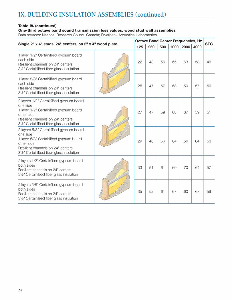
Table IV. (continued)One-third octave band sound transmission loss values, wood stud wall assembliesData sources: National Research Council Canada; Riverbank Acoustical Laboratories
Single 2" x 4" studs, 24" centers, on 2" x 4" wood plateOctave Band Center Frequencies, Hz
STC125 250 500 1000 2000 4000
1 layer 1/2" CertainTeed gypsum board each sideResilient channels on 24" centers3½" CertainTeed fi ber glass insulation
22 43 56 65 63 53 46
1 layer 5/8" CertainTeed gypsum board each sideResilient channels on 24" centers3½" CertainTeed fi ber glass insulation
26 47 57 63 50 57 50
2 layers 1/2" CertainTeed gypsum board one side1 layer 1/2" CertainTeed gypsum board other side Resilient channels on 24" centers3½" CertainTeed fi ber glass insulation
27 47 59 68 67 59 51
2 layers 5/8" CertainTeed gypsum board one side1 layer 5/8" CertainTeed gypsum board other side Resilient channels on 24" centers3½" CertainTeed fi ber glass insulation
29 46 56 64 56 64 53
2 layers 1/2" CertainTeed gypsum board both sidesResilient channels on 24" centers3½" CertainTeed fi ber glass insulation
33 51 61 69 70 64 57
2 layers 5/8" CertainTeed gypsum board both sidesResilient channels on 24" centers3½" CertainTeed fi ber glass insulation
35 52 61 67 60 68 59
IX. BUILDING INSULATION ASSEMBLIES (continued)
25
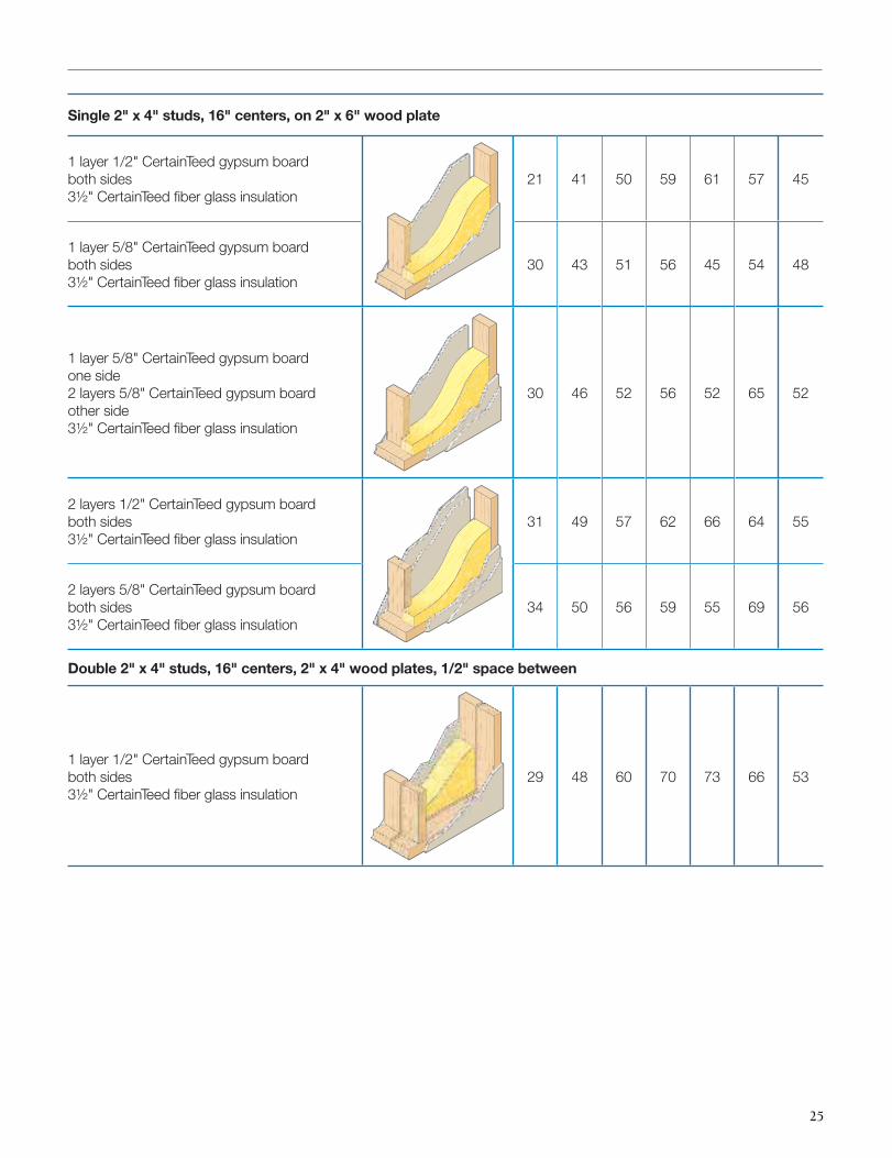
Single 2" x 4" studs, 16" centers, on 2" x 6" wood plate
1 layer 1/2" CertainTeed gypsum board both sides3½" CertainTeed fi ber glass insulation
21 41 50 59 61 57 45
1 layer 5/8" CertainTeed gypsum board both sides3½" CertainTeed fi ber glass insulation
30 43 51 56 45 54 48
1 layer 5/8" CertainTeed gypsum board one side2 layers 5/8" CertainTeed gypsum board other side3½" CertainTeed fi ber glass insulation
30 46 52 56 52 65 52
2 layers 1/2" CertainTeed gypsum board both sides3½" CertainTeed fi ber glass insulation
31 49 57 62 66 64 55
2 layers 5/8" CertainTeed gypsum board both sides3½" CertainTeed fi ber glass insulation
34 50 56 59 55 69 56
Double 2" x 4" studs, 16" centers, 2" x 4" wood plates, 1/2" space between
1 layer 1/2" CertainTeed gypsum board both sides3½" CertainTeed fi ber glass insulation
29 48 60 70 73 66 53
26
IX. BUILDING INSULATION ASSEMBLIES (continued)
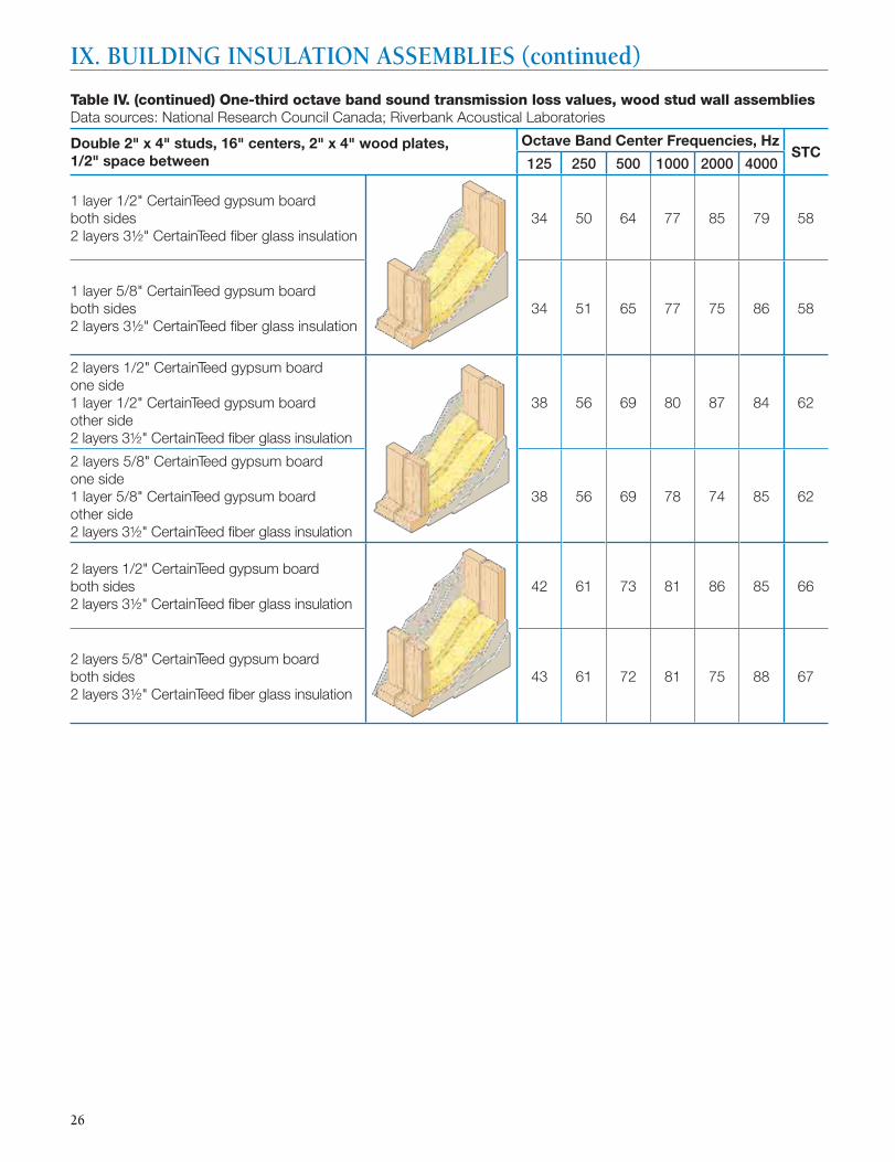
Table IV. (continued) One-third octave band sound transmission loss values, wood stud wall assembliesData sources: National Research Council Canada; Riverbank Acoustical Laboratories
Double 2" x 4" studs, 16" centers, 2" x 4" wood plates, 1/2" space between
Octave Band Center Frequencies, HzSTC
125 250 500 1000 2000 4000
1 layer 1/2" CertainTeed gypsum board both sides2 layers 3½" CertainTeed fi ber glass insulation
34 50 64 77 85 79 58
1 layer 5/8" CertainTeed gypsum board both sides2 layers 3½" CertainTeed fi ber glass insulation
34 51 65 77 75 86 58
2 layers 1/2" CertainTeed gypsum board one side1 layer 1/2" CertainTeed gypsum board other side 2 layers 3½" CertainTeed fi ber glass insulation
38 56 69 80 87 84 62
2 layers 5/8" CertainTeed gypsum board one side1 layer 5/8" CertainTeed gypsum board other side2 layers 3½" CertainTeed fi ber glass insulation
38 56 69 78 74 85 62
2 layers 1/2" CertainTeed gypsum board both sides 2 layers 3½" CertainTeed fi ber glass insulation
42 61 73 81 86 85 66
2 layers 5/8" CertainTeed gypsum board both sides2 layers 3½" CertainTeed fi ber glass insulation
43 61 72 81 75 88 67
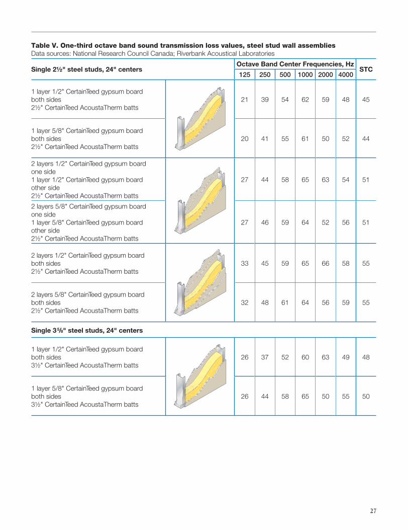
27
Table V. One-third octave band sound transmission loss values, steel stud wall assembliesData sources: National Research Council Canada; Riverbank Acoustical Laboratories
Single 2½" steel studs, 24" centersOctave Band Center Frequencies, Hz
STC125 250 500 1000 2000 4000
1 layer 1/2" CertainTeed gypsum board both sides2½" CertainTeed AcoustaTherm batts
21 39 54 62 59 48 45
1 layer 5/8" CertainTeed gypsum board both sides2½" CertainTeed AcoustaTherm batts
20 41 55 61 50 52 44
2 layers 1/2" CertainTeed gypsum board one side1 layer 1/2" CertainTeed gypsum board other side2½" CertainTeed AcoustaTherm batts
27 44 58 65 63 54 51
2 layers 5/8" CertainTeed gypsum board one side1 layer 5/8" CertainTeed gypsum board other side2½" CertainTeed AcoustaTherm batts
27 46 59 64 52 56 51
2 layers 1/2" CertainTeed gypsum board both sides2½" CertainTeed AcoustaTherm batts
33 45 59 65 66 58 55
2 layers 5/8" CertainTeed gypsum board both sides2½" CertainTeed AcoustaTherm batts
32 48 61 64 56 59 55
Single 35/8" steel studs, 24" centers
1 layer 1/2" CertainTeed gypsum board both sides3½" CertainTeed AcoustaTherm batts
26 37 52 60 63 49 48
1 layer 5/8" CertainTeed gypsum board both sides3½" CertainTeed AcoustaTherm batts
26 44 58 65 50 55 50

28
IX. BUILDING INSULATION ASSEMBLIES (continued)
Table V. (continued) One-third octave band sound transmission loss values, steel stud wall assembliesData sources: National Research Council Canada; Riverbank Acoustical Laboratories
Single 35/8" steel studs, 24" centersOctave Band Center Frequencies, Hz
STC125 250 500 1000 2000 4000
2 layers 1/2" CertainTeed gypsum board one side1 layer 1/2" CertainTeed gypsum board other side3½" CertainTeed AcoustaTherm batts
31 42 56 63 65 53 52
2 layers 5/8" CertainTeed gypsum board one side1 layer 5/8" CertainTeed gypsum board other side3½" CertainTeed AcoustaTherm batts
31 47 61 68 59 57 55
2 layers 1/2" CertainTeed gypsum board both sides3½" CertainTeed AcoustaTherm batts
31 48 61 68 65 58 55
2 layers 5/8" CertainTeed gypsum board both sides3½" CertainTeed AcoustaTherm batts
35 50 62 69 60 62 58
Single 6" steel studs, 24" centers
1 layer 5/8" CertainTeed gypsum board both sides6¼" CertainTeed AcoustaTherm batts
30 46 60 65 52 53 51
Chase walls – double steel stud, 24" centers
1 layer 1/2" CertainTeed gypsum board both sides2 layers 2½" CertainTeed AcoustaTherm batts
30 45 57 69 74 61 54
1 layer 5/8" CertainTeed gypsum board both sides2 layers 2½" CertainTeed AcoustaTherm batts
31 48 58 69 60 64 55
2 layers 1/2" CertainTeed gypsum board both sides2 layers 2½" CertainTeed AcoustaTherm batts
40 52 61 71 78 70 62
2 layers 5/8" CertainTeed gypsum board both sides2 layers 2½" CertainTeed AcoustaTherm batts
40 55 63 73 67 74 64
29
Acoustical Guide Specifi cation
Part 1 — General
1.01 Summary
A. Provide glass fi ber acoustical insulation as indicated in building plans.
1.02 Materials Provided in Other Sections
These sections are typically cross-referenced. Delete sections not included in project manual.
A. Section 09250 — Gypsum Board
B. Section 09260 — Gypsum Board Systems
C. Section 09100 — Metal Support Systems
1.03 References
A. ASTM Standards
1. ASTM E90, Laboratory Measurement of AirborneSound Transmission Loss of Building Partitions
2. ASTM E413, Rating Sound Insulation
3. ASTM E84, Test Method for Surface Burning Characteristics of Building Materials
4. ASTM E119, Method for Fire Tests of Building Construction Materials
5. ASTM E136, Test Method for Behavior of Materials in a Vertical Tube Furnace at 750°C
6. ASTM C518, Test Method for Steady State Thermal Transmission Properties by Means of the Heat Flow Meter
7. ASTM C665, Specifi cation for Mineral Fiber Blanket Thermal Insulation for Light Frame Construction and Manufactured Housing
1.04 Submittals
A. Product Data: Submit manufacturer’s product literature, samples, and installation instructions for specifi ed insulation.
1.05 Delivery, Storage, and Handling
A. Protect insulation from physical damage and from becoming wet, soiled, or covered with ice or snow. Comply with manufacturer’s recommendations for handling, storage, and protection during installation.
B. Label insulation packages to include material name, production date, and/or product code. Delete paragraph below if sections 01600 or 01620 are not included in project manual.
C. Deliver and store materials under provisions of section (01600) (01620).
1.06 Limitations
A. Do not use unfaced insulation in exposed applications where there is potential for skin contact and irritation.
Part 2 — Products
2.01 Manufacturer
A. CertainTeed Corporation, Valley Forge, PA, 19482
2.02 Material
(Specify name of CertainTeed fi ber glass insulation product)
A. Type: Unfaced fi ber glass insulation complying with ASTM C665.
B. Combustion characteristics: Passes ASTM E136 test.
C. Surface burning characteristics:
1. Maximum fl ame spread: 25.
2. Maximum smoke developed: 50 when tested in accordance with ASTM E84.*
D. Fire resistance rating: Passes ASTM E119 test.
E. Sound transmission class of the assembly: STC = ____
F. Size of insulation:
1. Thickness, ____________________________________
2. Width, _______________________________________
3. Length, ______________________________________
2.03 Gypsum Board
A. Refer to Section (09250) (09260) for detailed specifi cations. Select appropriate construction:
B. Type: 1/2" thick, CertainTeed gypsum panels
C. Type: 5/8" thick, CertainTeed gypsum panels
2.04 Metal Framing
A. Refer to Section (09250) (09260) for detailed specifi cations. Select appropriate construction:
B. Type: 2-1/2" steel stud
C. Type: 3-5/8" steel stud
* This standard is used solely to measure and describe the properties of products in response to heat and fl ame under controlled conditions. These numerical ratings are not intended to refl ect hazards presented by this or any other material under actual fi re conditions. Values are reported to the nearest 5 rating.
X. APPENDIX
30
Part 3 — Execution
3.01 Inspection and Preparation
A. Examine substrates and conditions under which insulation work is to be performed. A satisfactory substrate is one that complies with requirements of the section in which substrate and related work is specifi ed.
B. Obtain installer’s written report listing conditions detrimental to performance of work in this section. Do not proceed with installation until unsatisfactory conditions have been corrected.
C. Clean substrates of substances harmful to insulation.
3.02 Installation — General
A. Comply with manufacturer’s instructions for particular conditions of installation in each case.
B. Batts may be friction-fi t in place until the interior fi nish is applied. Install batts to fi ll entire stud cavity. If stud cavity is less than 96" in height, cut lengths to friction-fi t against fl oor and ceiling tracks. Walls with penetrations require that insulation be carefully cut to fi t around outlets, junction boxes, and other irregularities.
C. Where insulation must extend higher then 8 feet, supplementary support can be provided to hold product in place until the interior fi nish is applied.
Acoustical material: Any material considered in terms of its acoustical properties. Commonly and especially, a material designed to absorb sound.
Airborne sound: Sound which arrives at the point of concern, such as one side of a wall, by propagation through air.
A-weighted sound level (dB): The most common single number rating system for measuring the loudness of a noise. It may be read directly on most sound level meters by selecting the designated scale. It is obtained by applying the A-weighted frequency response curve to the measured sound. The response curve is indicative of the way humans respond to different frequencies.
Attenuation: The reduction in magnitude of airborne sound pressure level between two points in the sound transmission path from source to receiver.
Background noise: Noise from all sources unrelated to a particular sound that is the object of interest. Background noise may include airborne, structureborne, and instrument noise.
Decibel (dB): The term used to identify ten times the common logarithm of the ratio of two like quantities proportional to power or energy. (See Sound transmission loss.) Thus, one decibel corresponds to a power ratio of (10 to the 0.1 power) to the n power. Note: Since the decibel expresses the ratio of two like quantities, it has no dimensions. It is, however, common practice to treat “decibel” as a unit, as for example in the sentence: “The average sound pressure level in the room is 45 decibels.”
Diffuse sound fi eld: The sound in a region where the intensity is the same in all directions and at every point.
Direct sound fi eld: The sound that arrives directly from a source without refl ection.
Flanking transmission: The transmission of sound between two rooms by any path other than directly through a common partition.
Frequency: The number of cycles per second measured in units of Hertz (Hz). One hertz is one complete oscillation per second. A frequency of 1000 Hz means 1000 cycles per second.
Impact insulation class (IIC): A single number rating derived from measured values of normalized impact sound pressure levels in accordance with Annex 1 of ASTM Method E492, Laboratory Measurement of Impact Sound Transmission Through Floor-Ceiling Assemblies Using the Tapping Machine. It provides an estimate of the impact sound insulation performance of a fl oor-ceiling assembly.
Noise: Unwanted sound.
X. APPENDIX (continued)
Glossary of Acoustical Terms

31
Noise isolation class (NIC): A single number rating calculated from measured values of noise reduction as though they were values of transmission loss. The NIC determined in accordance with ASTM Standard E413, Determination of Sound Transmission Class. It provides an estimate of the sound isolation between two enclosed spaces that are acoustically connected.
Noise reduction (NR): In a specifi ed frequency band, the difference between the space-time average sound pressure levels produced in two enclosed spaces or one of them. Note: it is implied that in each room individual observations are randomly distributed about the average value, with no systematic variation within the position within the permissible measurement region. Noise reduction becomes meaningless and should not be used in situations where this condition is not met.
Noise reduction coeffi cient (NRC): A single number rating derived from measured values of sound absorption coeffi cients in accordance with ASTM Test Method C423, Sound Absorption and Sound Absorption Coeffi cients by the Reverberation Room Method. It provides an estimate of the sound absorptive property of an acoustical material. NRC values range from 0 for hard, refl ective materials such as fl at glass and gypsum board to 1.2 for several inches of highly effi cient fi ber glass.
Octave band: A range of frequency where the highest frequency of the band is double the lowest frequency of the band. The band is usually specifi ed by the center frequency.
Reverberation: The persistence of sound in an enclosed or partially enclosed space after the source of the sound has stopped.
Reverberation time: The time required for the average sound intensity of an enclosed space to decrease by 60 dB after the sound source becomes silent.
Sabin: The unit of measure of sound absorption in the inch-pound system.
Sound absorption average (SAA): A single number rating similar to the NRC used to express the sound absorbing properties of a material. It is equal to the average of the sound absorption coeffi cients of a material from 200 through 2500 Hz.
Sound absorption coeffi cient (a, dimensionless): Metric sabin/m2 of a surface, in a specifi ed frequency band. The measure of the absorptive property of a material as approximated by ASTM Test Method C423, Sound Absorption and Sound Absorption Coeffi cients by the Reverberation Room Method. Ideally, the fraction of the randomly incident sound power level absorbed or not otherwise refl ected.
Sound attenuation: (1) The reduction of the intensity of a sound as it travels from the source to a receiving location. Sound absorption is often involved as, for instance, in a lined air duct. (2) Spherical spreading and scattering or other attenuation mechanisms.
Sound level meter: An instrument that measured sound pressure levels with a microphone which converts sound pressure waves to an electrical signal.
Sound pressure level (Lp): Of airborne sound, ten times the common logarithm of the ratio of the square of the sound pressure under consideration to the square of the standard reference pressure of 20 microPa. The quantity so obtained is expressed in decibels.
Sound transmission class (STC): A single number rating derived from measured values of transmission in accordance with ASTM Classifi cation E413, Determination of Sound Transmission Class. It provides an estimate of the performance of a partition in certain common sound insulation problems.
Sound transmission loss (STL): Of a partition, in a specifi ed frequency band, the times the common logarithm of the ratio of the airborne sound power incident on the partition to the sound power transmitted by the partition and radiated on the other side. The quantity so obtained is expressed in decibels. Note: Unless qualifi ed, the term denotes the sound transmission loss obtained when the specimen is exposed to a diffuse sound fi eld as approximated in reverberation rooms meeting the requirements of ASTM Test Method E90, Laboratory Measurement of Airborne Sound Transmission Loss of Building Partitions.
Speech intelligibility: The proportion of meaningful speech that is correctly interpreted by a listener.
Structureborne sound: Sound that arrives at the point of concern by propagation through a solid structure.
“Let the word be heard.” Anne Seltz, Audiologist
32
Worksheet for calculation of room noise reduction and reverberation time.
Noise reduction in a room due to the addition of sound absorption:
A. Calculation of sabins in room before sound absorption is added
1. Area of various walls: ________________ ___________________ ___________________ ___________________
2. Absorption coeffi cient: _______________ ___________________ ___________________ ___________________
3. Sabins (1x2): _______________________ ___________________ ___________________ ___________________
4. Area of fl oor: __________________________x Absorption coeffi cient = ______________________sabins
5. Area of ceiling: ________________________x Absorption coeffi cient = ______________________sabins
6. Sabins of other surfaces in the room (area x abs. coeff.): ____________________________________________________
7. Total sabins in room: ___________________________________________sabins
B. Calculation of sabins in room after sound absorption is added
1. Area of various walls: ________________ ___________________ ___________________ ___________________
2. Absorption coeffi cient: _______________ ___________________ ___________________ ___________________
3. Sabins (1x2): _______________________ ___________________ ___________________ ___________________
4. Area of fl oor: __________________________x Absorption coeffi cient = _____________________sabins
5. Area of ceiling: _________________________x Absorption coeffi cient = _____________________sabins
6. Sabins of other surfaces in the room (area x abs. coeff.): ____________________________________________________
7. Total sabins in room: _______________________________________________________________sabins
C. Calculation of noise reduction
1. Divide value in line B.7 by A.7
2. Take the logarithm to the base 10 of the result from C.1
3. Multiply the value from C.3 by 10
4. The result is the amount of noise reduction in dB at the chosen frequency
D. Calculation of reverberation time in a room
1. Calculate the volume of the room in cubic feet.
2. Multiply the volume of the room by 0.049
3. Determine the total amount of sabins in the room (see above calculations for determining sabins in a room)
4. Divide the value from line 2 by the value from line 3. This is the reverberation time in seconds.
FOR FURTHER READING on the subject of noise control:
• ASHRAE Handbook, HVAC Applications, 1999
• Leo L. Beranek: Noise Reduction. McGraw-Hill, 1960
• L. L. Faulkner: Handbook of Industrial Noise Control. Industrial Press, Inc., 1976
• Cyril M. Harris: Handbook of Acoustical Measurements and Noise Control, third edition.Acoustical Society of America, Item #1-56396-774
• Cyril M. Harris: Noise Control in Buildings. McGraw-Hill, 1994
• Karl D. Kryter: The Effects of Noise on Man. Academic Press, 1970
• Mark E. Schaffer: A Practical Guide to Noise and Vibration Control for HVAC Systems. Available from ASHRAE.
X. APPENDIX (continued)

33
Rating: 2 hour non-bearing (U 419)Double layer 1/2" CertainTeed gypsum board2½" steel studs on 24" centers2½" CertainTeed fi ber glass insulation
Rating: 2 hour non-bearing (U 411 or U 419)Double layer 5/8" CertainTeed gypsum board35/8" steel studs on 24" centers3½" CertainTeed fi ber glass insulation
Rating: 1 hour non-bearing (U 465 or U 419)Single layer 5/8" CertainTeed gypsum board
on each side6" steel studs on 24" centers6¼" CertainTeed fi ber glass insulation
Rating: 2 hour non-bearing (U 411)Double layer 5/8" CertainTeed gypsum boardMin. 2½" steel studs on 24" centers2½" CertainTeed fi ber glass insulation
Rating: 2 hour non-bearing (U 436)Chase wall: Double layer 5/8" CertainTeed
gypsum board15/8" steel studs on 24" centersCertainTeed fi ber glass insulation to fi ll cavity
Rating: 1 hour non-bearing (U 419)Single layer 5/8" CertainTeed gypsum boardMin. 3½" steel studs on 24" centers3½" CertainTeed fi ber glass insulation Rating: 1 hour non-bearing (U 420)
Chase wall: Single layer 5/8" CertainTeed gypsum board
15/8" steel studs on 24" centers3½" CertainTeed fi ber glass insulation
Rating: 2 hour non-bearing (U 419)Double layer 1/2" CertainTeed gypsum board35/8" steel studs on 24" centers3½" CertainTeed fi ber glass insulation
Rating: 1 hour non-bearing (U 465 or U 419)Single layer 5/8" CertainTeed gypsum board35/8" steel studs on 24" centers3½" CertainTeed fi ber glass insulation
Rating: 2 hour non-bearing (U 497)Shaft wall: Single layer 1" Type FSW gypsum
board one side, double layer 1/2" Type FSW-G gypsum board other side
2½" steel I studs on 24" centers1½" CertainTeed CertaPro partition insulation
Rating: 1 hour bearing (U 341)Single layer 5/8" CertainTeed gypsum board
on each side2" x 4" double wood studs on 24" centers2 layers 3½" CertainTeed fi ber glass insulation
Note: Drawings for illustration purposes only. Refer to Underwriters Laboratories Fire Resistance Directory for assembly details and other options.
Rating 1 hour non-bearing (U 465)Single layer 5/8" CertainTeed gypsum board35/8" steel studs on 24" centers3½" CertainTeed fi ber glass insulation
Rating: 2 hour non-bearing (U 498)Shaft wall: Double layer (1" CertainTeed + 1/2"
Type FSW) gypsum board on one side, single layer 1/2" Type FSW-G gypsum board on other side
2½" steel I studs on 24" centers1½" CertainTeed CertaPro partition insulation
Rating: 1 hour non-bearing (U 419)Single layer 5/8" CertainTeed gypsum boardMin. 3½" steel studs on 24" centers3½" CertainTeed fi ber glass insulation
Rating: 1 hour non-bearing (U 499)Shaft wall: Single layer 1" Type FSW gypsum
board on one side, single layer 5/8" Type FSW gypsum board on other side
2½" steel I studs on 24" centers1½" CertainTeed CertaPro partition insulation
Rating: 2 hour non-bearing (U 420)Chase wall: Double layer 5/8" CertainTeed
gypsum board15/8" steel studs on 24" centers2½" CertainTeed fi ber glass insulation
Rating: 1 hour bearing (U 305) Single layer 5/8" CertainTeed gypsum board
on each side2" x 4" wood studs on 16" centers3½" CertainTeed fi ber glass insulation
Rating: 2 hour non-bearing (U 419)Double layer 5/8" CertainTeed gypsum board
on each side6" steel studs on 24" centers6¼" CertainTeed fi ber glass insulation
Rating: 3/4 hour bearing (U 317)Single layer 1/2" CertainTeed gypsum board
on each side2" x 4" wood studs on 16" centers 3½" CertainTeed fi ber glass insulation
Fire Rated Wall Assemblies — these drawings are a useful aid for fi re rated wall assemblies
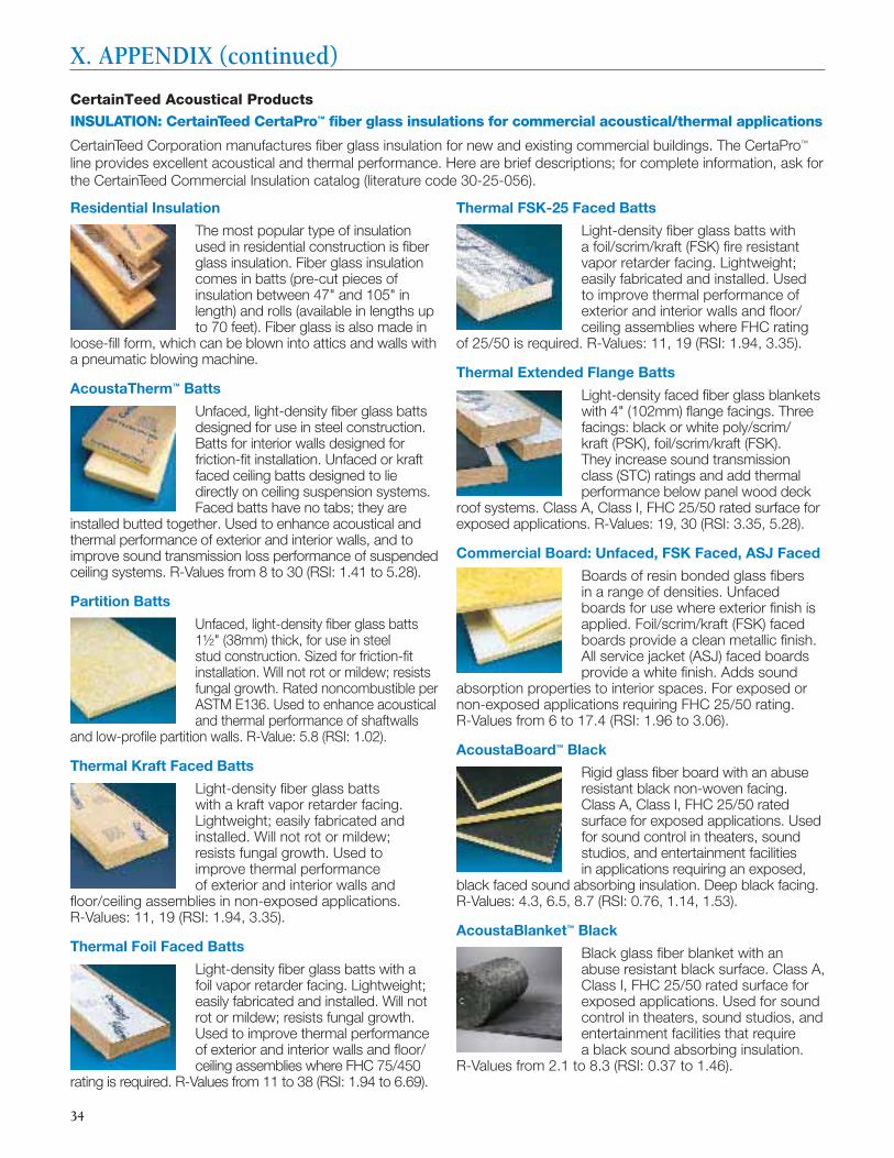
34
Residential Insulation
The most popular type of insulation used in residential construction is fi ber glass insulation. Fiber glass insulation comes in batts (pre-cut pieces of insulation between 47" and 105" in length) and rolls (available in lengths up to 70 feet). Fiber glass is also made in
loose-fi ll form, which can be blown into attics and walls with a pneumatic blowing machine.
AcoustaTherm™ Batts
Unfaced, light-density fi ber glass batts designed for use in steel construction. Batts for interior walls designed for friction-fi t installation. Unfaced or kraft faced ceiling batts designed to lie directly on ceiling suspension systems. Faced batts have no tabs; they are
installed butted together. Used to enhance acoustical and thermal performance of exterior and interior walls, and to improve sound transmission loss performance of suspended ceiling systems. R-Values from 8 to 30 (RSI: 1.41 to 5.28).
Partition Batts
Unfaced, light-density fi ber glass batts 1½" (38mm) thick, for use in steel stud construction. Sized for friction-fi t installation. Will not rot or mildew; resists fungal growth. Rated noncombustible per ASTM E136. Used to enhance acoustical and thermal performance of shaftwalls
and low-profi le partition walls. R-Value: 5.8 (RSI: 1.02).
Thermal Kraft Faced Batts
Light-density fi ber glass batts with a kraft vapor retarder facing. Lightweight; easily fabricated and installed. Will not rot or mildew; resists fungal growth. Used to improve thermal performance of exterior and interior walls and
fl oor/ceiling assemblies in non-exposed applications. R-Values: 11, 19 (RSI: 1.94, 3.35).
Thermal Foil Faced Batts
Light-density fi ber glass batts with a foil vapor retarder facing. Lightweight; easily fabricated and installed. Will not rot or mildew; resists fungal growth. Used to improve thermal performance of exterior and interior walls and fl oor/ceiling assemblies where FHC 75/450
rating is required. R-Values from 11 to 38 (RSI: 1.94 to 6.69).
Thermal FSK-25 Faced Batts
Light-density fi ber glass batts with a foil/scrim/kraft (FSK) fi re resistant vapor retarder facing. Lightweight; easily fabricated and installed. Used to improve thermal performance of exterior and interior walls and fl oor/ceiling assemblies where FHC rating
of 25/50 is required. R-Values: 11, 19 (RSI: 1.94, 3.35).
Thermal Extended Flange Batts
Light-density faced fi ber glass blankets with 4" (102mm) fl ange facings. Three facings: black or white poly/scrim/kraft (PSK), foil/scrim/kraft (FSK). They increase sound transmission class (STC) ratings and add thermal performance below panel wood deck
roof systems. Class A, Class I, FHC 25/50 rated surface for exposed applications. R-Values: 19, 30 (RSI: 3.35, 5.28).
Commercial Board: Unfaced, FSK Faced, ASJ Faced
Boards of resin bonded glass fi bers in a range of densities. Unfaced boards for use where exterior fi nish is applied. Foil/scrim/kraft (FSK) faced boards provide a clean metallic fi nish. All service jacket (ASJ) faced boards provide a white fi nish. Adds sound
absorption properties to interior spaces. For exposed or non-exposed applications requiring FHC 25/50 rating. R-Values from 6 to 17.4 (RSI: 1.96 to 3.06).
AcoustaBoard™ Black
Rigid glass fi ber board with an abuse resistant black non-woven facing. Class A, Class I, FHC 25/50 rated surface for exposed applications. Used for sound control in theaters, sound studios, and entertainment facilities in applications requiring an exposed,
black faced sound absorbing insulation. Deep black facing. R-Values: 4.3, 6.5, 8.7 (RSI: 0.76, 1.14, 1.53).
AcoustaBlanket™ Black
Black glass fi ber blanket with an abuse resistant black surface. Class A, Class I, FHC 25/50 rated surface for exposed applications. Used for sound control in theaters, sound studios, and entertainment facilities that require a black sound absorbing insulation.
R-Values from 2.1 to 8.3 (RSI: 0.37 to 1.46).
CertainTeed Acoustical Products
INSULATION: CertainTeed CertaPro™ fi ber glass insulations for commercial acoustical/thermal applications
CertainTeed Corporation manufactures fi ber glass insulation for new and existing commercial buildings. The CertaPro™ line provides excellent acoustical and thermal performance. Here are brief descriptions; for complete information, ask for the CertainTeed Commercial Insulation catalog (literature code 30-25-056).
X. APPENDIX (continued)
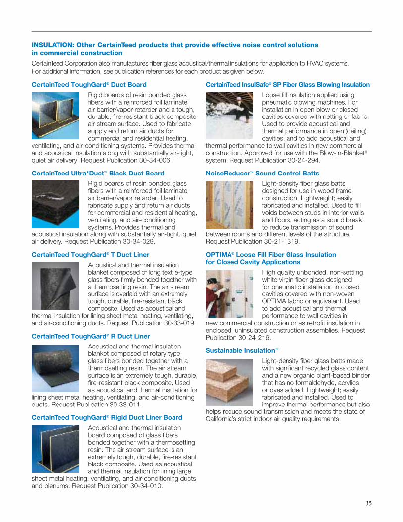
35
CertainTeed ToughGard® Duct Board
Rigid boards of resin bonded glass fi bers with a reinforced foil laminate air barrier/vapor retarder and a tough, durable, fi re-resistant black composite air stream surface. Used to fabricate supply and return air ducts for commercial and residential heating,
ventilating, and air-conditioning systems. Provides thermal and acoustical insulation along with substantially air-tight, quiet air delivery. Request Publication 30-34-006.
CertainTeed Ultra*Duct™ Black Duct Board
Rigid boards of resin bonded glass fi bers with a reinforced foil laminate air barrier/vapor retarder. Used to fabricate supply and return air ducts for commercial and residential heating, ventilating, and air-conditioning systems. Provides thermal and
acoustical insulation along with substantially air-tight, quiet air delivery. Request Publication 30-34-029.
CertainTeed ToughGard® T Duct Liner
Acoustical and thermal insulation blanket composed of long textile-type glass fi bers fi rmly bonded together with a thermosetting resin. The air stream surface is overlaid with an extremely tough, durable, fi re-resistant black composite. Used as acoustical and
thermal insulation for lining sheet metal heating, ventilating, and air-conditioning ducts. Request Publication 30-33-019.
CertainTeed ToughGard® R Duct Liner
Acoustical and thermal insulation blanket composed of rotary type glass fi bers bonded together with a thermosetting resin. The air stream surface is an extremely tough, durable, fi re-resistant black composite. Used as acoustical and thermal insulation for
lining sheet metal heating, ventilating, and air-conditioning ducts. Request Publication 30-33-011.
CertainTeed ToughGard® Rigid Duct Liner Board
Acoustical and thermal insulation board composed of glass fi bers bonded together with a thermosetting resin. The air stream surface is an extremely tough, durable, fi re-resistant black composite. Used as acoustical and thermal insulation for lining large
sheet metal heating, ventilating, and air-conditioning ducts and plenums. Request Publication 30-34-010.
CertainTeed InsulSafe® SP Fiber Glass Blowing Insulation
Loose fi ll insulation applied using pneumatic blowing machines. For installation in open blow or closed cavities covered with netting or fabric. Used to provide acoustical and thermal performance in open (ceiling) cavities, and to add acoustical and
thermal performance to wall cavities in new commercial construction. Approved for use with the Blow-In-Blanket® system. Request Publication 30-24-294.
NoiseReducer™ Sound Control Batts
Light-density fi ber glass batts designed for use in wood frame construction. Lightweight; easily fabricated and installed. Used to fi ll voids between studs in interior walls and fl oors, acting as a sound break to reduce transmission of sound
between rooms and different levels of the structure. Request Publication 30-21-1319.
OPTIMA® Loose Fill Fiber Glass Insulation for Closed Cavity Applications
High quality unbonded, non-settling white virgin fi ber glass designed for pneumatic installation in closed cavities covered with non-woven OPTIMA fabric or equivalent. Used to add acoustical and thermal performance to wall cavities in
new commercial construction or as retrofi t insulation in enclosed, uninsulated construction assemblies. Request Publication 30-24-216.
Sustainable Insulation™
Light-density fi ber glass batts made with signifi cant recycled glass content and a new organic plant-based binder that has no formaldehyde, acrylics or dyes added. Lightweight; easily fabricated and installed. Used to improve thermal performance but also
helps reduce sound transmission and meets the state of California’s strict indoor air quality requirements.
INSULATION: Other CertainTeed products that provide effective noise control solutions in commercial construction
CertainTeed Corporation also manufactures fi ber glass acoustical/thermal insulations for application to HVAC systems. For additional information, see publication references for each product as given below.
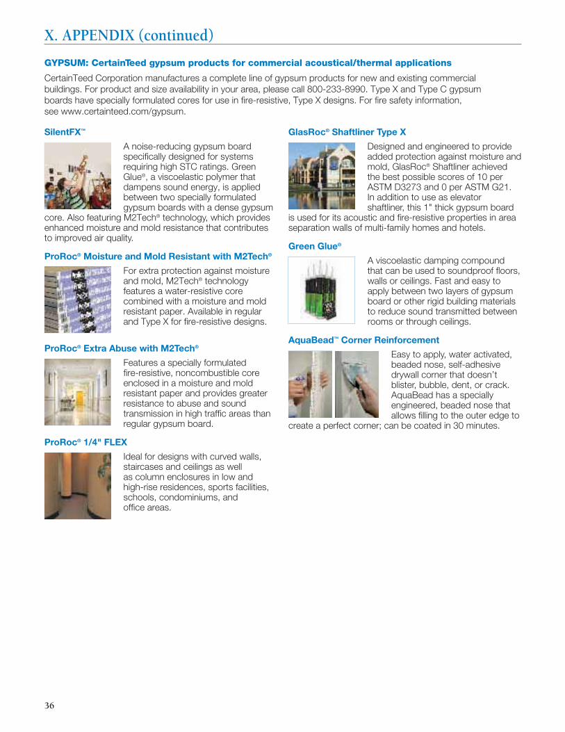
36
SilentFX™
A noise-reducing gypsum board specifi cally designed for systems requiring high STC ratings. Green Glue®, a viscoelastic polymer that dampens sound energy, is applied between two specially formulated gypsum boards with a dense gypsum
core. Also featuring M2Tech® technology, which provides enhanced moisture and mold resistance that contributes to improved air quality.
ProRoc® Moisture and Mold Resistant with M2Tech®
For extra protection against moisture and mold, M2Tech® technology features a water-resistive core combined with a moisture and mold resistant paper. Available in regular and Type X for fi re-resistive designs.
ProRoc® Extra Abuse with M2Tech®
Features a specially formulated fi re-resistive, noncombustible core enclosed in a moisture and mold resistant paper and provides greater resistance to abuse and sound transmission in high traffi c areas than regular gypsum board.
ProRoc® 1/4" FLEX
Ideal for designs with curved walls, staircases and ceilings as well as column enclosures in low and high-rise residences, sports facilities, schools, condominiums, and offi ce areas.
GlasRoc® Shaftliner Type X
Designed and engineered to provide added protection against moisture and mold, GlasRoc® Shaftliner achieved the best possible scores of 10 per ASTM D3273 and 0 per ASTM G21. In addition to use as elevator shaftliner, this 1" thick gypsum board
is used for its acoustic and fi re-resistive properties in area separation walls of multi-family homes and hotels.
Green Glue®
A viscoelastic damping compound that can be used to soundproof fl oors, walls or ceilings. Fast and easy to apply between two layers of gypsum board or other rigid building materials to reduce sound transmitted between rooms or through ceilings.
AquaBead™ Corner Reinforcement
Easy to apply, water activated, beaded nose, self-adhesive drywall corner that doesn’t blister, bubble, dent, or crack. AquaBead has a specially engineered, beaded nose that allows fi lling to the outer edge to
create a perfect corner; can be coated in 30 minutes.
GYPSUM: CertainTeed gypsum products for commercial acoustical/thermal applications
CertainTeed Corporation manufactures a complete line of gypsum products for new and existing commercial buildings. For product and size availability in your area, please call 800-233-8990. Type X and Type C gypsum boards have specially formulated cores for use in fi re-resistive, Type X designs. For fi re safety information, see www.certainteed.com/gypsum.
36
X. APPENDIX (continued)

37
Adagio® and Adagio® High CAC
Unique composite ceiling panel that offers optimum acoustical performance. The encapsulated fi berglass layer provides exceptional sound absorption (0.80/0.90 NRC). The mineral backboard offers highly effective sound containment (36-42
CAC). Adagio and Adagio High CAC can enhance space privacy compliance for HIPPAA and GLBA.
Ecophon® Focus™ Dg
Superior sound absorption combined with the unique aesthetic of a partially concealed grid system. Ecophon Focus Dg panels are downward accessible for easy access to plenum. With an NRC of 0.80, Ecophon Focus Dg provides superior noise reduction
without compromising the overall design or functionality.
Ecophon® Focus™ Ds
Superior sound absorption in a monolithic aesthetic. Ecophon Focus Ds panels fully conceal the suspension system, while maintaining downward accessibility. The high NRC of 0.80 provides for quieter work spaces. The panel also has a premium
Akutex FT white fi nish with perfect light diffusion (+99%) to enhance daylighting.
Ecophon® Gedina® A, E
A high density fi berglass ceiling panel offering superior sound absorption with an NRC of 0.85 in a very thin, fl exible panel that is humidity resistant and water repellent. Ecophon Gedina allows for easier integration with suspended systems
that must fi t very close to the structure.
Ecophon® Master™ A, E
Fine-tune acoustic design using Ecophon Master A and E. Three unique surface treatments allow for different acoustical properties. This allows for ideal absorption at certain frequencies for applications that are more sensitive to sound
treatments. Ideal for auditoriums, classrooms, and music practice rooms.
Ecophon® Solo
A free-hanging, Class A sound absorption panel that combines easy installation with an attractive appearance. Because of its free-hanging design, Ecophon Solo has the added advantage of being able to absorb sound from all directions. The
Akutex FT white fi nish ensures high light refl ectance with perfect light diffusion (+99%) to enhance daylighting.
Symphony® f
Superior noise reduction (NRC 0.80-0.95) to maximize interzone attenuation. Overtone® facing provides a clean, monolithic look with exceptional durability and scrubbability. Available in a wide range of panel sizes and thicknesses.
CEILINGS: CertainTeed acoustical ceiling products for commercial applications
CertainTeed Corporation offers a complete line of acoustical ceiling products that contribute to a superior environment for the eye, the ear, and the mind. The products described briefl y below provide excellent acoustical solutions for a broad range of applications; for complete information, ask for the CertainTeed Ceilings product catalog or visit www.certainteed.com/ceilings.
37
www.certainteed.com/insulation
CertainTeed CorporationP.O. Box 860
Valley Forge, PA 19482
Professional: 800-233-8990Consumer: 800-782-8777
© 07/11 CertainTeed Corporation30-29-121
ASK ABOUT ALL OF OUR OTHER CERTAINTEED® PRODUCTS AND SYSTEMS:
ROOFING • SIDING • TRIM • WINDOWS • DECKING • RAILING • FENCEINSULATION • GYPSUM • CEILINGS • FOUNDATIONS • PIPE
For additional resources about acoustical information and product solutions:
www.mysoundchek.com
www.certainteed.com/ceilings
www.certainteed.com/gypsum
www.acoustics.com
www.isover.com/Q-A/Choice-of-insulation-material/How-to-choose-acoustic-insulation
www.wbdg.org/resources/acoustic.php