odot traffic sign design manual - · pdf fileodot traffic sign design manual 3rd edition...
TRANSCRIPT
ODOT Traffic Sign Design Manual
3rd Edition
Oregon Department of Transportation
Technical Services
Traffic-Roadway Section
Traffic Standards & Asset Management Unit http://www.oregon.gov/ODOT/HWY/TS/Pages/signing.aspx
Oregon Department of Transportation
Traffic Standards Unit
OD
OT
Traffi
c Si
gn D
esig
n M
anu
al
3rd Edition
ODOT Traffic Sign Design Manual 3rd
Edition
Oregon Department of Transportation i Foreword
Traffic Standards Unit July 2015
ODOT Traffic Sign Design Manual
Version 03-03 – July 2015
Heidi E. Shoblom, P.E.
ODOT Sign Engineer Traffic Standards & Asset Management Unit
The material contained herein is for information purposes only and may be used to aid new employees
and those unfamiliar with ODOT Traffic Engineering practices, in accessing and applying applicable
standards, statutes, rules, and policies related to traffic sign design.
This manual was authored by Greg Stellmach, former ODOT Sign Engineer, and is maintained by the
current ODOT Sign Engineer. Comments can be emailed to Heidi Shoblom, ODOT Sign Engineer.
Oregon Department of Transportation
Technical Services
Traffic-Roadway Section Traffic Standards & Asset Management Unit
http://www.oregon.gov/ODOT/HWY/TS/Pages/signing.aspx
3rd
Edition ODOT Traffic Sign Design Manual
Foreword ii Oregon Department of Transportation
July 2015 Traffic Standards Unit
Department of Transportation
Traffic-Roadway Section, MS#5
Traffic Standards & Asset Management Unit
4040 Fairview Industrial Drive
Salem, Oregon 97302-1142
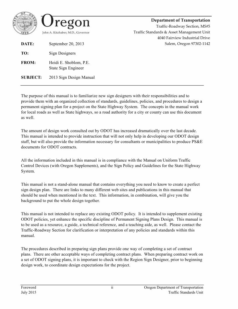
DATE: September 20, 2013
TO: Sign Designers
FROM: Heidi E. Shoblom, P.E.
State Sign Engineer
SUBJECT: 2013 Sign Design Manual
The purpose of this manual is to familiarize new sign designers with their responsibilities and to
provide them with an organized collection of standards, guidelines, policies, and procedures to design a
permanent signing plan for a project on the State Highway System. The concepts in the manual work
for local roads as well as State highways, so a road authority for a city or county can use this document
as well.
The amount of design work consulted out by ODOT has increased dramatically over the last decade.
This manual is intended to provide instruction that will not only help in developing our ODOT design
staff, but will also provide the information necessary for consultants or municipalities to produce PS&E
documents for ODOT contracts.
All the information included in this manual is in compliance with the Manual on Uniform Traffic
Control Devices (with Oregon Supplements), and the Sign Policy and Guidelines for the State Highway
System.
This manual is not a stand-alone manual that contains everything you need to know to create a perfect
sign design plan. There are links to many different web sites and publications in this manual that
should be used when mentioned in the text. This information, in combination, will give you the
background to put the whole design together.
This manual is not intended to replace any existing ODOT policy. It is intended to supplement existing
ODOT policies, yet enhance the specific discipline of Permanent Signing Plans Design. This manual is
to be used as a resource, a guide, a technical reference, and a teaching aide, as well. Please contact the
Traffic-Roadway Section for clarification or interpretation of any policies and standards within this
manual.
The procedures described in preparing sign plans provide one way of completing a set of contract
plans. There are other acceptable ways of completing contract plans. When preparing contract work on
a set of ODOT signing plans, it is important to check with the Region Sign Designer, prior to beginning
design work, to coordinate design expectations for the project.
ODOT Traffic Sign Design Manual 3rd
Edition
Oregon Department of Transportation iii Foreword
Traffic Standards Unit July 2015
Contents
1 | Developing Plans .................................................................................................................... 2
Project Scope .........................................................................................................................................2
Treatment of Existing Signs and Supports ............................................................................................2
Critical Sign Locations ..........................................................................................................................4
Sign Spacing ........................................................................................................................................19
Sign Specific Needs and Guidance ......................................................................................................20
2 | Designing Signs ..................................................................................................................... 28
Choosing Substrate and Sheeting Types..............................................................................................28
Designing Regulatory and Warning Signs ..........................................................................................33
Designing Guide Signs ........................................................................................................................34
3 | Designing Supports .............................................................................................................. 40
Choosing a Support Type ....................................................................................................................40
Wood Posts ..........................................................................................................................................40
Steel Supports ......................................................................................................................................40
Other Supports .....................................................................................................................................42
4 | Drafting Standards .............................................................................................................. 46
General ................................................................................................................................................46
Plan Sheets ...........................................................................................................................................49
Sign Details .........................................................................................................................................56
Sign and Post Data Tables ...................................................................................................................62
Sheet Numbers .....................................................................................................................................75
Archiving of Files ................................................................................................................................75
5 | Standards .............................................................................................................................. 78
Standard Drawings and Standard Details ............................................................................................78
Standard Specifications and Special Provisions ..................................................................................78
6 | Estimates ............................................................................................................................... 82
List of Bid Items ..................................................................................................................................82
Providing Quantities ............................................................................................................................84
Unit Costs and Regional Factors .........................................................................................................86
Anticipated Items .................................................................................................................................86
3rd
Edition ODOT Traffic Sign Design Manual
Foreword iv Oregon Department of Transportation
July 2015 Traffic Standards Unit
7 | Design Follow-Up ................................................................................................................. 90
Construction Support .......................................................................................................................... 90
Shop Drawings / Submittals ............................................................................................................... 90
8 | Special Design Considerations ............................................................................................ 94
Review Requirements for Interstate Signing ...................................................................................... 94
Appendix A | Signing Contacts ................................................................................................ 98
Project Leader / Consultant Project Manager ..................................................................................... 98
Roadway Designer .............................................................................................................................. 98
Specification Writer ............................................................................................................................ 98
Region Sign Designer ......................................................................................................................... 98
Traffic-Roadway Section Staff ........................................................................................................... 99
District Sign Supervisor/Coordinator ................................................................................................. 99
State Parks .......................................................................................................................................... 99
Oregon Travel Experience (OTE) ...................................................................................................... 99
Right-of-Way ...................................................................................................................................... 99
Sign Structures Designer .................................................................................................................. 100
Geotechnical Engineer ...................................................................................................................... 100
Landscape Designer .......................................................................................................................... 100
Other Traffic Designers .................................................................................................................... 100
Project Manager (and Inspector) ...................................................................................................... 100
Bicycle & Pedestrian Program Manager .......................................................................................... 101
Construction Materials Inspection Lab ............................................................................................. 101
Survey Crew ..................................................................................................................................... 101
Appendix B | Sign Design Resources ..................................................................................... 102
Existing Sign Inventory & Photos .................................................................................................... 102
Digital Video Log ............................................................................................................................. 102
Manual on Uniform Traffic Control Devices (MUTCD) ................................................................. 102
Standard Highway Signs Manual ..................................................................................................... 103
Oregon Supplements to the MUTCD ............................................................................................... 103
Sign Policy & Guidelines for the State Highway System ................................................................ 103
ODOT Traffic Manual ...................................................................................................................... 103
Speed Zone Orders ........................................................................................................................... 104
No Parking Resolution ...................................................................................................................... 104
ODOT Traffic Sign Design Manual 3rd
Edition
Oregon Department of Transportation v Foreword
Traffic Standards Unit July 2015
Contract Plans Development Guide...................................................................................................105
Standard Specifications and Special Provisions ................................................................................105
Standard Drawings ............................................................................................................................105
As-Built Plans ....................................................................................................................................105
Oregon Bicycle and Pedestrian Plan ..................................................................................................106
OARs and ORSs ................................................................................................................................106
Qualified Products List ......................................................................................................................106
Traffic Control Devices Handbook ...................................................................................................106
Interstate Highways Control Cities List ............................................................................................107
Appendix C | Level of Development ...................................................................................... 108
Design Acceptance Package ..............................................................................................................108
Preliminary Plans ...............................................................................................................................108
Advance Plans and Specifications .....................................................................................................109
Plans-In-Hand Meeting ......................................................................................................................109
Final Plans and Specifications ...........................................................................................................109
Appendix D | Sign Sizes .......................................................................................................... 111
Appendix E | Mileage Control Table ..................................................................................... 113
Appendix F | Abbreviations ................................................................................................... 123
3rd
Edition ODOT Traffic Sign Design Manual
Foreword vi Oregon Department of Transportation
July 2015 Traffic Standards Unit
Figures
Figure 1 | Standard Signing for Safety Corridors ......................................................................................... 5
Figure 2 | Typical Speed Zone Signing ........................................................................................................ 6
Figure 3 | Standard Signing for Passing or Climbing Lanes......................................................................... 7
Figure 4 | Standard Signing for Slow Moving Vehicle Turnouts ................................................................. 7
Figure 5 | Standard Rural Left Turn Refuge Signing ................................................................................... 8
Figure 6 | Transition Signing for Physical Separation of Lanes ................................................................... 8
Figure 7 | Weigh Station Signing Off-Interstate (MUTCD Figure 2D-17, ref.) ........................................... 9
Figure 8 | Weigh Station Signing Interstate with Weigh-In-Motion .......................................................... 11
Figure 9 | Regulatory Signing at Exit Ramp (MUTCD Figure 2B-18, ref.) ............................................... 12
Figure 10 | Typical Guide Signing at Exit Ramp ....................................................................................... 12
Figure 11 | Typical Signing for Exit Ramp with Right Turn Lane ............................................................. 13
Figure 12 | Low Mount Signing – Standard Ramp Terminal ..................................................................... 13
Figure 13 | Enhanced Wrong Way Signing – Folded Diamond Ramp Terminal ....................................... 14
Figure 14 | Low Mount Signing – Ramp Terminal with Concrete Island .................................................. 14
Figure 15 | Low Mount Sign Installations – Freeway Ramp Terminals ..................................................... 15
Figure 16 | Typical Ramp Meter Signing Layout ....................................................................................... 16
Figure 17 | Typical Ramp Meter Signing Layout (Overhead Ramp Meter Installation) ............................ 17
Figure 18 | Typical Ramp Meter Signing Layout (Ground Mounted Ramp Meter Installation) ................ 18
Figure 19 | Sample Plan Sheet .................................................................................................................... 50 Figure 20 | Sample Plan Sheet .................................................................................................................... 51
Figure 21 | Sample Plan Sheet .................................................................................................................... 52
Figure 22 | Sample Plan Sheet .................................................................................................................... 53
Figure 23 | Sample Detail Sheet ................................................................................................................. 58
Figure 24 | Sample Detail Sheet ................................................................................................................. 59
Figure 25 | Sample Detail Sheet ................................................................................................................. 60
Figure 26 | Sample Sign and Post Data Table ............................................................................................ 70
Figure 27 | Sample Sign and Post Data Table ............................................................................................ 71
Figure 28 | Sample Sign and Post Data Table ............................................................................................ 72
Figure 29 | Sample Sign and Post Data Table ............................................................................................ 73
Figure 30 | Sample Sign and Post Data Table ............................................................................................ 74
Figure 31 | Cost Estimating Spreadsheet .................................................................................................... 83
ODOT Traffic Sign Design Manual 3rd
Edition
Oregon Department of Transportation vii Foreword
Traffic Standards Unit July 2015
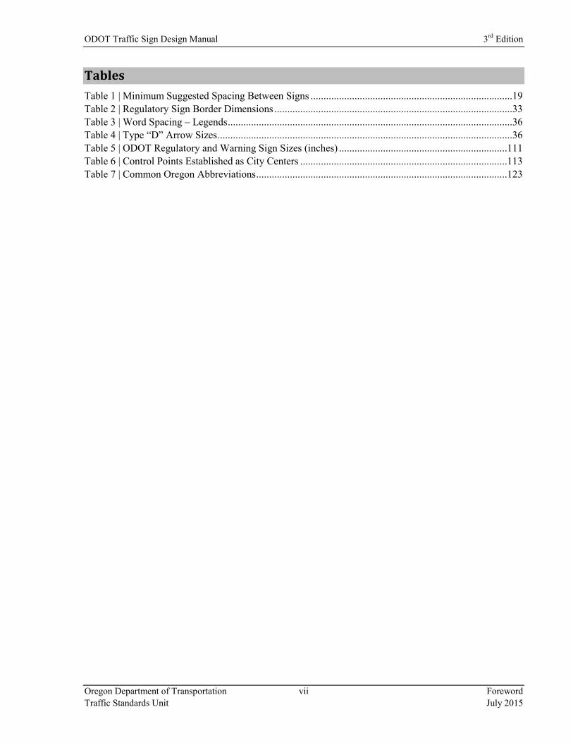
Tables
Table 1 | Minimum Suggested Spacing Between Signs ..............................................................................19
Table 2 | Regulatory Sign Border Dimensions ............................................................................................33
Table 3 | Word Spacing – Legends ..............................................................................................................36
Table 4 | Type “D” Arrow Sizes ..................................................................................................................36
Table 5 | ODOT Regulatory and Warning Sign Sizes (inches) .................................................................111
Table 6 | Control Points Established as City Centers ................................................................................113
Table 7 | Common Oregon Abbreviations .................................................................................................123

3rd
Edition ODOT Traffic Sign Design Manual
Foreword viii Oregon Department of Transportation
July 2015 Traffic Standards Unit
(This page intentionally left blank.)
Chapter 1
Developing Plans
3rd Edition
ODOT Traffic Sign Design Manual

3rd
Edition ODOT Traffic Sign Design Manual
Chapter 1 | Developing Plans 2 Oregon Department of Transportation
July 2015 Traffic Standards Unit
1 | Developing Plans
Project Scope
The first information needed is the scope of the work to be accomplished. There are many types of
highway construction projects, and the type of work to be performed will have a big effect on the scope of
the work for the permanent signing. A preservation overlay, for example, will not directly impact
existing signs in the same manner as a modernization project that includes major widening, alignment
changes, and changes in grade, yet signing should not be ignored in the preservation project. Even when
existing signing seems to be unaffected, a designer must still evaluate whether it meets all minimum
standards set for signing on our highway system. More specific details about the various standards for
designing signs and sign supports appear in Chapter 2 and Chapter 3 of this manual.
For most projects, the physical limits (stations, mile points) for the signing plans will coincide with those
of the roadway plans. Some projects, however, may not include roadway work and still others may be
limited to signing work only. In these cases, the designer should contact the Project Leader or Consultant
Project Manager for information such as project limits, or scope of signing work. In some instances, the
signing limits will need to extend beyond those of the roadway plans. For example, the project paving
limits could end in the middle of a school zone, in which case the designer should include all of the
signing for that school zone in the sign plans. A project may only involve realignment of ramps at an
interchange, but it may actually necessitate changes in guide signs a mile in advance of that interchange.
A small widening project to create a left turn lane will require striping and signing changes for ¼ mile in
advance of each end of the left turn lane. These are just a few of the scenarios in which the signing limits
would exceed the roadway limits.
Each project is unique, so the scope of the signing work to be performed can vary widely from one project
to the next. Identifying the full scope of the work to be performed early on will make the design process
go more smoothly.
Treatment of Existing Signs and Supports
When gathering information to create your sign plan, you need to determine which signs need replacing.
On some modernization projects, you will replace everything. On some preservation projects, you will
only replace some of the signs. This depends on the scope of work, how it affects existing sign
installations, and the condition of those signs.
The sign designer must replace the signs that do not meet the minimum requirements of the MUTCD or
State Sign Policy. Since the MUTCD and Sign Policy are updated frequently, you will need to keep
informed of current standards. You can accomplish this by paying close attention to the resource manuals
listed in Appendix B.
ODOT Traffic Sign Design Manual 3rd
Edition
Oregon Department of Transportation 3 Chapter 1 | Developing Plans
Traffic Standards Unit July 2015
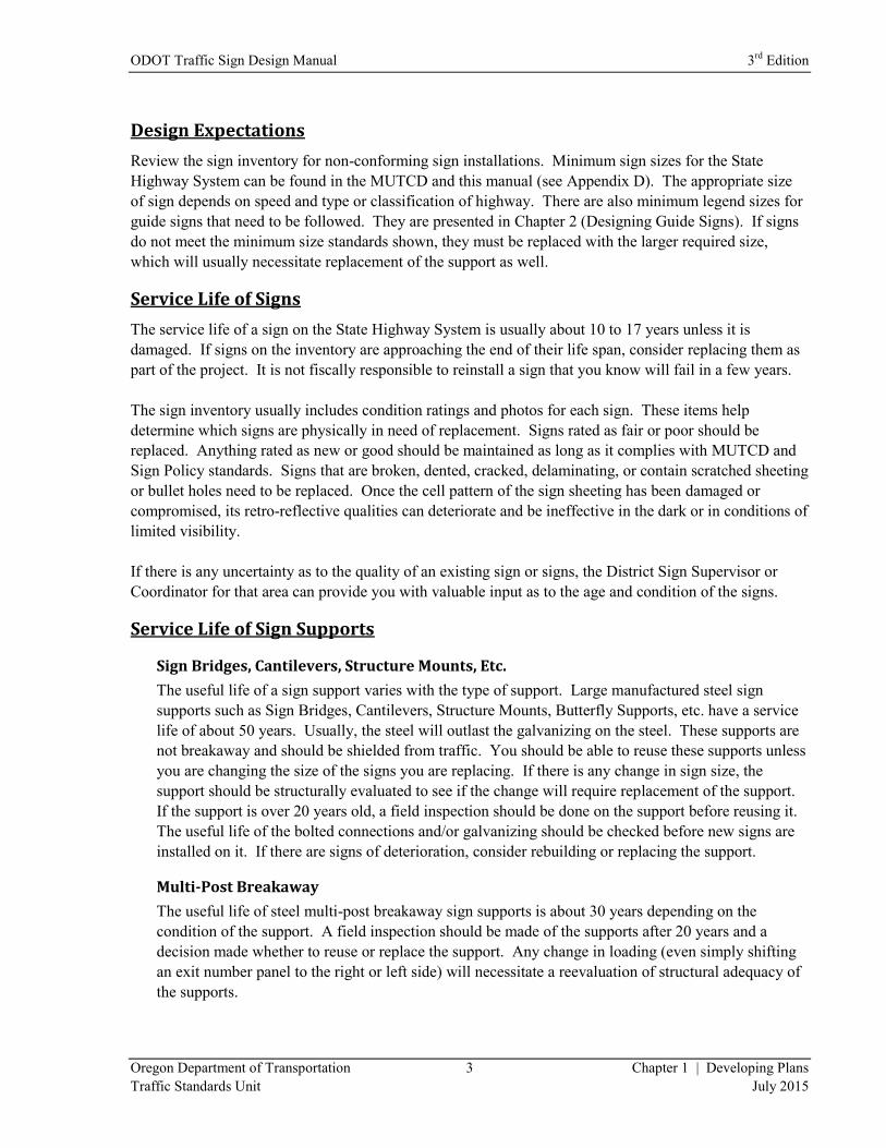
Design Expectations
Review the sign inventory for non-conforming sign installations. Minimum sign sizes for the State
Highway System can be found in the MUTCD and this manual (see Appendix D). The appropriate size
of sign depends on speed and type or classification of highway. There are also minimum legend sizes for
guide signs that need to be followed. They are presented in Chapter 2 (Designing Guide Signs). If signs
do not meet the minimum size standards shown, they must be replaced with the larger required size,
which will usually necessitate replacement of the support as well.
Service Life of Signs
The service life of a sign on the State Highway System is usually about 10 to 17 years unless it is
damaged. If signs on the inventory are approaching the end of their life span, consider replacing them as
part of the project. It is not fiscally responsible to reinstall a sign that you know will fail in a few years.
The sign inventory usually includes condition ratings and photos for each sign. These items help
determine which signs are physically in need of replacement. Signs rated as fair or poor should be
replaced. Anything rated as new or good should be maintained as long as it complies with MUTCD and
Sign Policy standards. Signs that are broken, dented, cracked, delaminating, or contain scratched sheeting
or bullet holes need to be replaced. Once the cell pattern of the sign sheeting has been damaged or
compromised, its retro-reflective qualities can deteriorate and be ineffective in the dark or in conditions of
limited visibility.
If there is any uncertainty as to the quality of an existing sign or signs, the District Sign Supervisor or
Coordinator for that area can provide you with valuable input as to the age and condition of the signs.
Service Life of Sign Supports
Sign Bridges, Cantilevers, Structure Mounts, Etc.
The useful life of a sign support varies with the type of support. Large manufactured steel sign
supports such as Sign Bridges, Cantilevers, Structure Mounts, Butterfly Supports, etc. have a service
life of about 50 years. Usually, the steel will outlast the galvanizing on the steel. These supports are
not breakaway and should be shielded from traffic. You should be able to reuse these supports unless
you are changing the size of the signs you are replacing. If there is any change in sign size, the
support should be structurally evaluated to see if the change will require replacement of the support.
If the support is over 20 years old, a field inspection should be done on the support before reusing it.
The useful life of the bolted connections and/or galvanizing should be checked before new signs are
installed on it. If there are signs of deterioration, consider rebuilding or replacing the support.
Multi-Post Breakaway
The useful life of steel multi-post breakaway sign supports is about 30 years depending on the
condition of the support. A field inspection should be made of the supports after 20 years and a
decision made whether to reuse or replace the support. Any change in loading (even simply shifting
an exit number panel to the right or left side) will necessitate a reevaluation of structural adequacy of
the supports.
3rd
Edition ODOT Traffic Sign Design Manual
Chapter 1 | Developing Plans 4 Oregon Department of Transportation
July 2015 Traffic Standards Unit
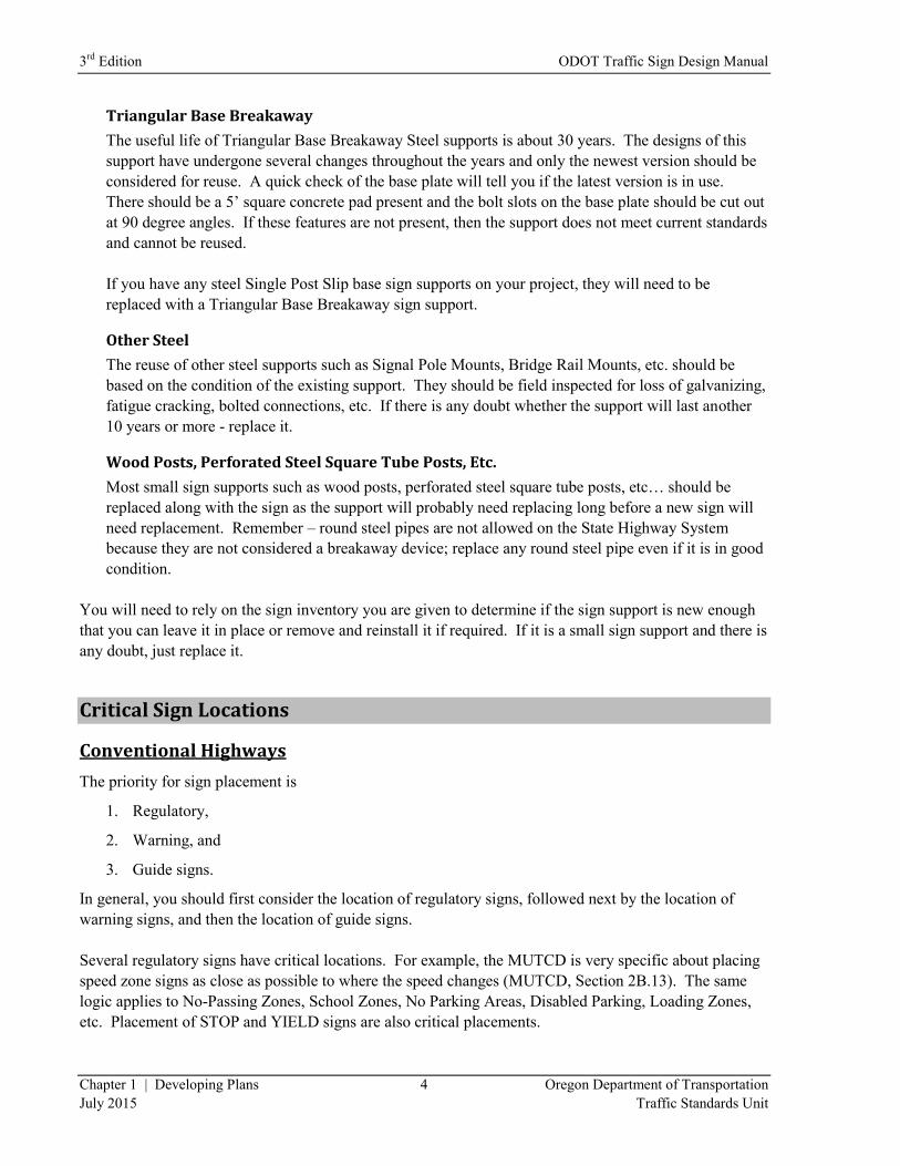
Triangular Base Breakaway
The useful life of Triangular Base Breakaway Steel supports is about 30 years. The designs of this
support have undergone several changes throughout the years and only the newest version should be
considered for reuse. A quick check of the base plate will tell you if the latest version is in use.
There should be a 5’ square concrete pad present and the bolt slots on the base plate should be cut out
at 90 degree angles. If these features are not present, then the support does not meet current standards
and cannot be reused.
If you have any steel Single Post Slip base sign supports on your project, they will need to be
replaced with a Triangular Base Breakaway sign support.
Other Steel
The reuse of other steel supports such as Signal Pole Mounts, Bridge Rail Mounts, etc. should be
based on the condition of the existing support. They should be field inspected for loss of galvanizing,
fatigue cracking, bolted connections, etc. If there is any doubt whether the support will last another
10 years or more - replace it.
Wood Posts, Perforated Steel Square Tube Posts, Etc.
Most small sign supports such as wood posts, perforated steel square tube posts, etc… should be
replaced along with the sign as the support will probably need replacing long before a new sign will
need replacement. Remember – round steel pipes are not allowed on the State Highway System
because they are not considered a breakaway device; replace any round steel pipe even if it is in good
condition.
You will need to rely on the sign inventory you are given to determine if the sign support is new enough
that you can leave it in place or remove and reinstall it if required. If it is a small sign support and there is
any doubt, just replace it.
Critical Sign Locations
Conventional Highways
The priority for sign placement is
1. Regulatory,
2. Warning, and
3. Guide signs.
In general, you should first consider the location of regulatory signs, followed next by the location of
warning signs, and then the location of guide signs.
Several regulatory signs have critical locations. For example, the MUTCD is very specific about placing
speed zone signs as close as possible to where the speed changes (MUTCD, Section 2B.13). The same
logic applies to No-Passing Zones, School Zones, No Parking Areas, Disabled Parking, Loading Zones,
etc. Placement of STOP and YIELD signs are also critical placements.
ODOT Traffic Sign Design Manual 3rd
Edition
Oregon Department of Transportation 5 Chapter 1 | Developing Plans
Traffic Standards Unit July 2015
Warning signs have the next highest priority for location placement. These include Stop or Signal Ahead
Symbol signs, curve warning signs, chevrons, DEAD END, NO OUTLET, Object Markers, etc.
After the regulatory and warning sign locations have been established, the guide sign locations can be
considered. These include placing street name signs on all intersecting roadways, installing route shield
assemblies (if required), destination and distance signs, City Hall, Library, Airport, Train Station,
permissive parking and park & ride signs, etc.
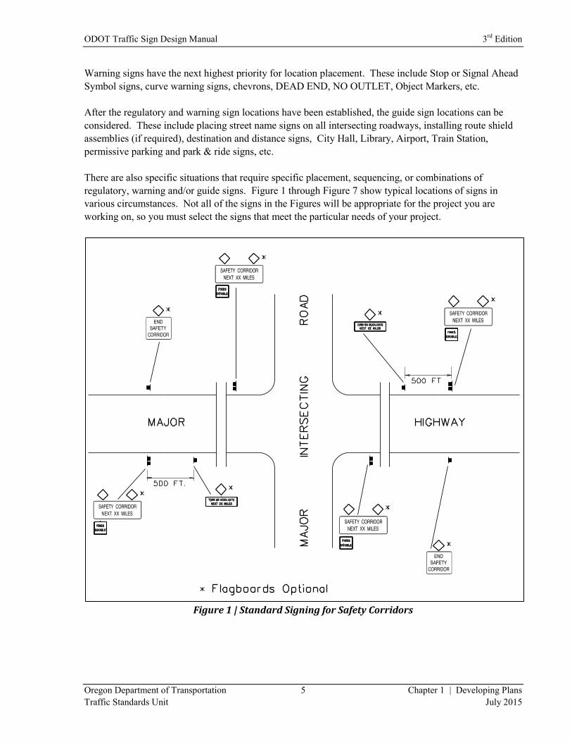
There are also specific situations that require specific placement, sequencing, or combinations of
regulatory, warning and/or guide signs. Figure 1 through Figure 7 show typical locations of signs in
various circumstances. Not all of the signs in the Figures will be appropriate for the project you are
working on, so you must select the signs that meet the particular needs of your project.
Figure 1 | Standard Signing for Safety Corridors
3rd
Edition ODOT Traffic Sign Design Manual
Chapter 1 | Developing Plans 6 Oregon Department of Transportation
July 2015 Traffic Standards Unit
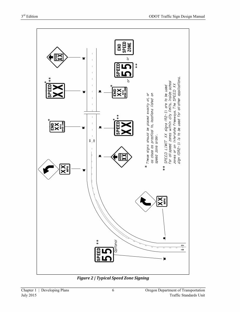
Figure 2 | Typical Speed Zone Signing
ODOT Traffic Sign Design Manual 3rd
Edition
Oregon Department of Transportation 7 Chapter 1 | Developing Plans
Traffic Standards Unit July 2015
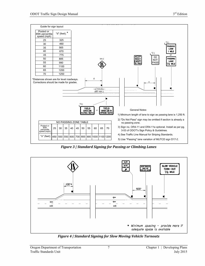
Figure 3 | Standard Signing for Passing or Climbing Lanes
Figure 4 | Standard Signing for Slow Moving Vehicle Turnouts
3rd
Edition ODOT Traffic Sign Design Manual
Chapter 1 | Developing Plans 8 Oregon Department of Transportation
July 2015 Traffic Standards Unit
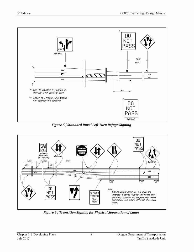
Figure 5 | Standard Rural Left Turn Refuge Signing
Figure 6 | Transition Signing for Physical Separation of Lanes
ODOT Traffic Sign Design Manual 3rd
Edition
Oregon Department of Transportation 9 Chapter 1 | Developing Plans
Traffic Standards Unit July 2015
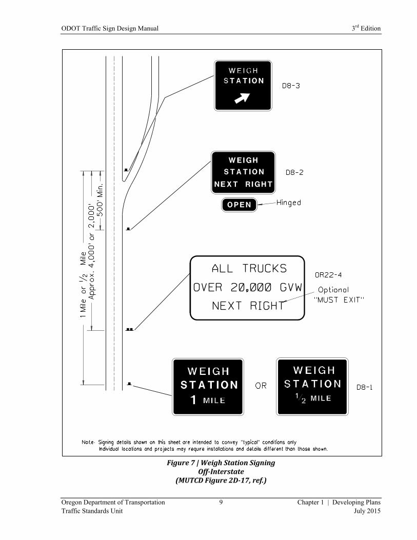
Figure 7 | Weigh Station Signing
Off-Interstate (MUTCD Figure 2D-17, ref.)
3rd
Edition ODOT Traffic Sign Design Manual
Chapter 1 | Developing Plans 10 Oregon Department of Transportation
July 2015 Traffic Standards Unit
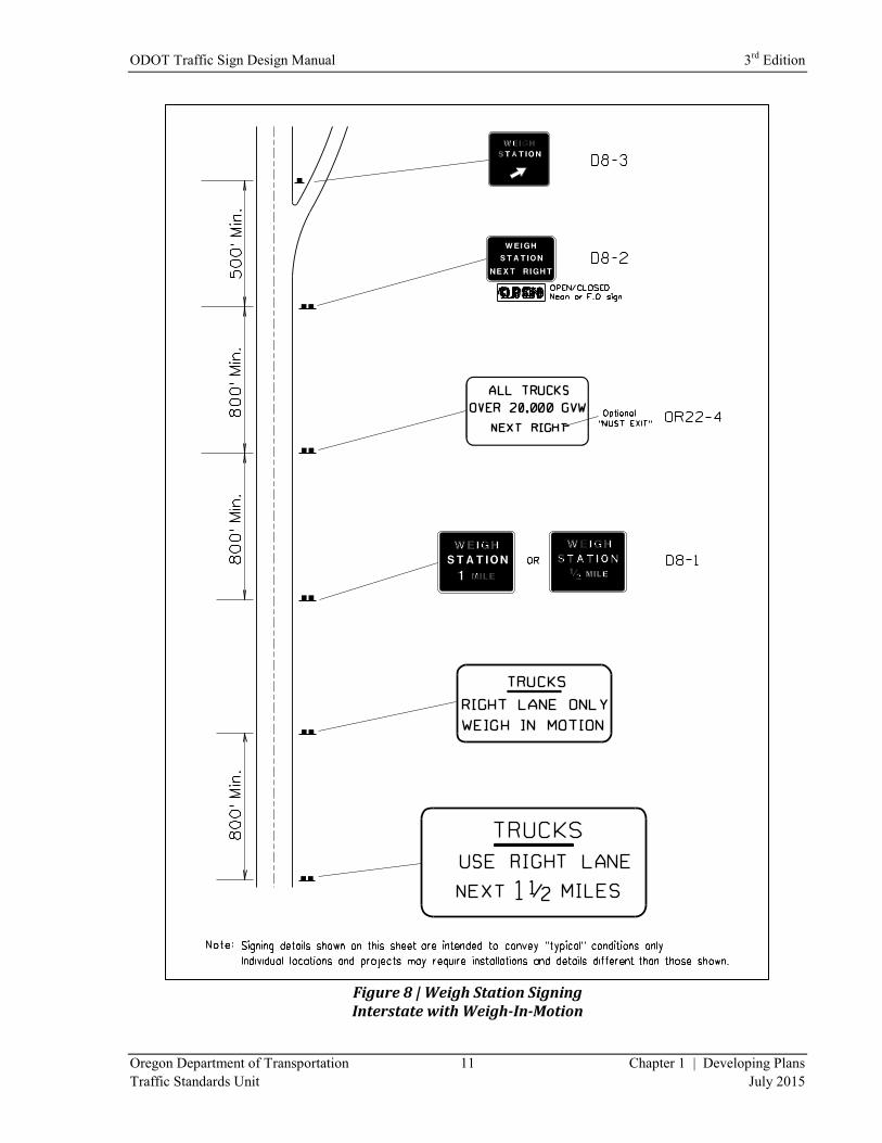
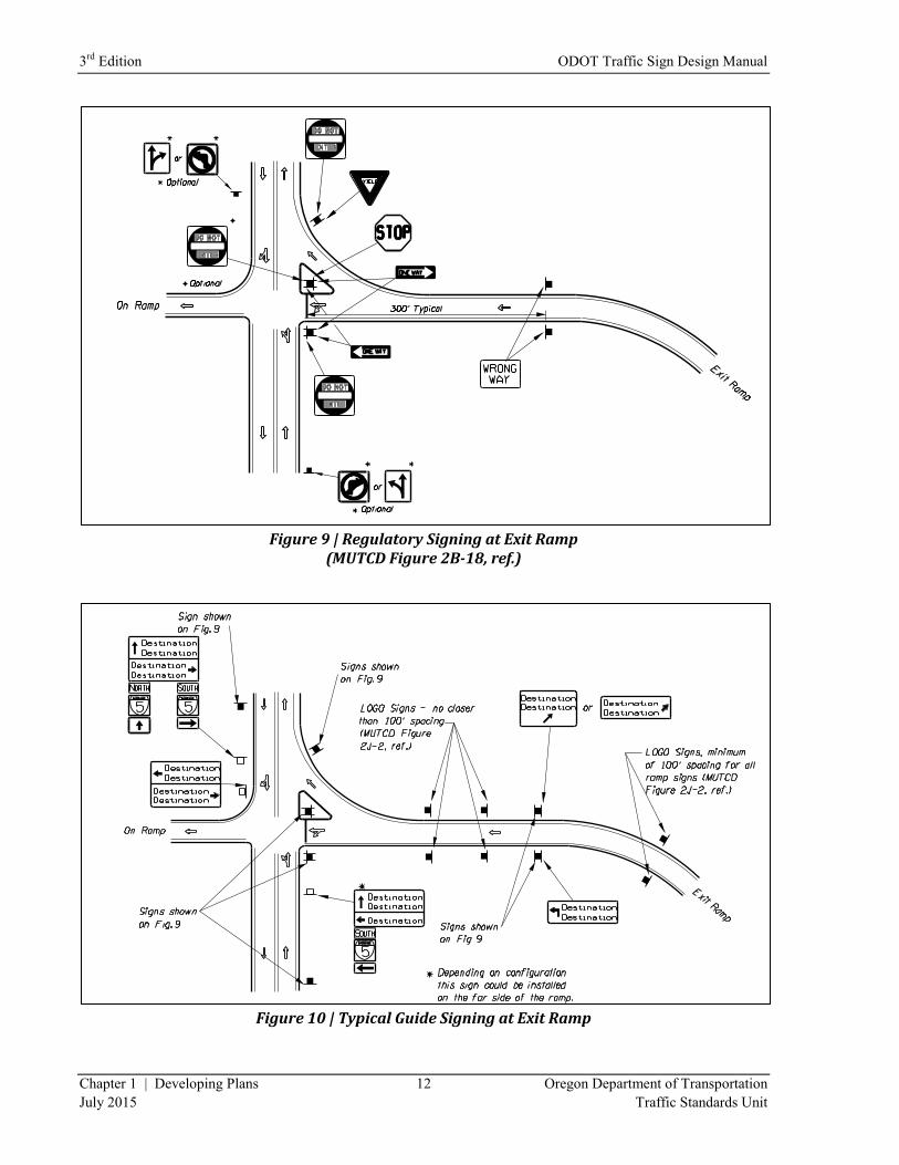
Freeways and Expressways
For freeways and expressways, several types of signs have critical locations for placement. Most of the
critical locations relate to interchanges as they are the beginning point for measurements. Figure 9
through Figure 11 show the locations mandated for Ramp Terminal signing.
On freeways and expressways, a minimum spacing of 800 feet between all large guide signs should be
maintained (Reference: “ITE Traffic Control Devices Handbook, 2001, Sign Spreading, Page 52).
Use Figure 9 through Figure 11 to determine the locations for the DO NOT ENTER, ONE WAY,
WRONG WAY, STOP, and Stop or Signal Ahead Symbol signs. The MUTCD allows signs on Ramps
every 100’ following the EXIT SPEED sign. Review the other existing signs and arrange them in a
sequence that gives the driver enough notice that they can get into the appropriate lane to make their turn
at the ramp terminal. Remember the priority for signs is: Regulatory, Warning, and then Guide signs.
Use the back of the posts of the DO NOT ENTER and WRONG WAY signs for signs facing the opposite
direction.
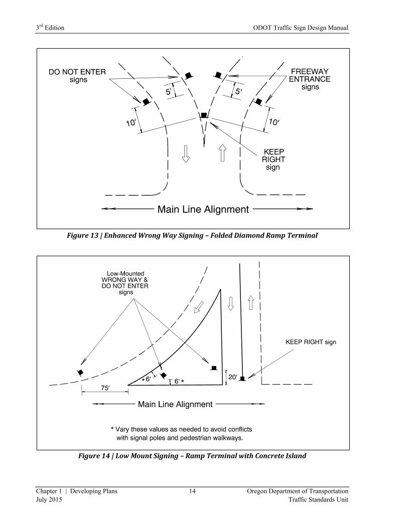
Figure 12 through Figure 15 provide additional guidance regarding low mounted installations for Wrong
Way Entrance signing on the Interstate. Prevention of wrong-way traffic movement is a concern
whenever an entire roadway is dedicated to one-way traffic, especially on high speed facilities like the
Interstate where instances of wrong way driving often result in very damaging or fatal crashes. MUTCD
Section 2E.53 provides guidance in the placement of signs to discourage wrong way driving. A
combination of ONE-WAY, DO NOT ENTER, and WRONG-WAY signs is recommended. The
MUTCD also allows for lane use arrows and markings. MUTCD Section 2B.41 includes new language
that would allow for the use of a lower mounting height for signs in locations where an engineering study
indicates it would address the issue of wrong way movements.
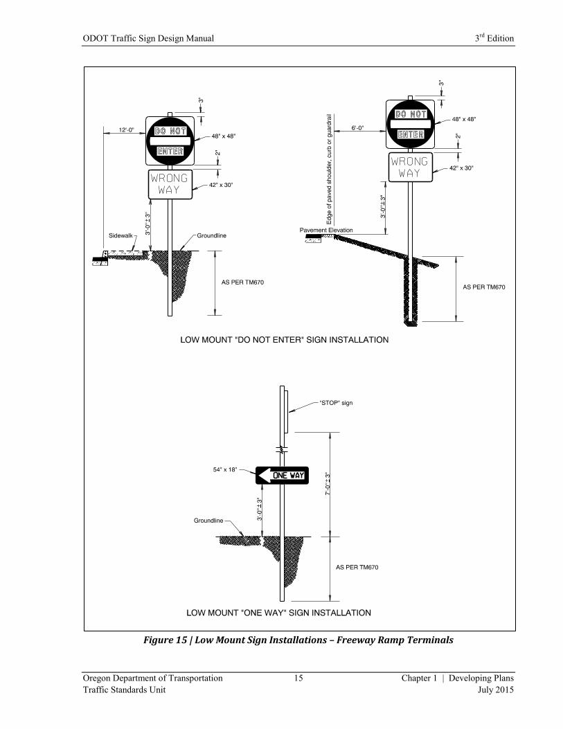
In order to implement the use of low mounted sign installations to prevent wrong way entrances at
freeway exits, ODOT has adopted a standard for low mounted installations (Figure 15) along with
guidance for where they are required (Figure 12 through Figure 14), depending on certain roadway
geometrics commonly used at interchanges on the Interstate.
Because wrong way entrance signs are typically installed at a 45 degree angle to approaching traffic and
because of the limited performance of high intensity sign sheeting for night time retroreflectivity when
viewed at angles other than 90 degrees to approaching traffic, all installations for wrong way entrance
signing shall use wide angle prismatic sheeting (ASTM Type IX or better).
Sign designers are responsible for doing a field inspection of the proposed location to determine if there
are circumstances that would impede the ability of drivers to view low mounted installations (e.g. Barrier,
fencing, snow embankment, etc.). If the designer determines the signs will not be clearly visible at the
lower mounting height, the signs shall be installed at the standard mounting height.
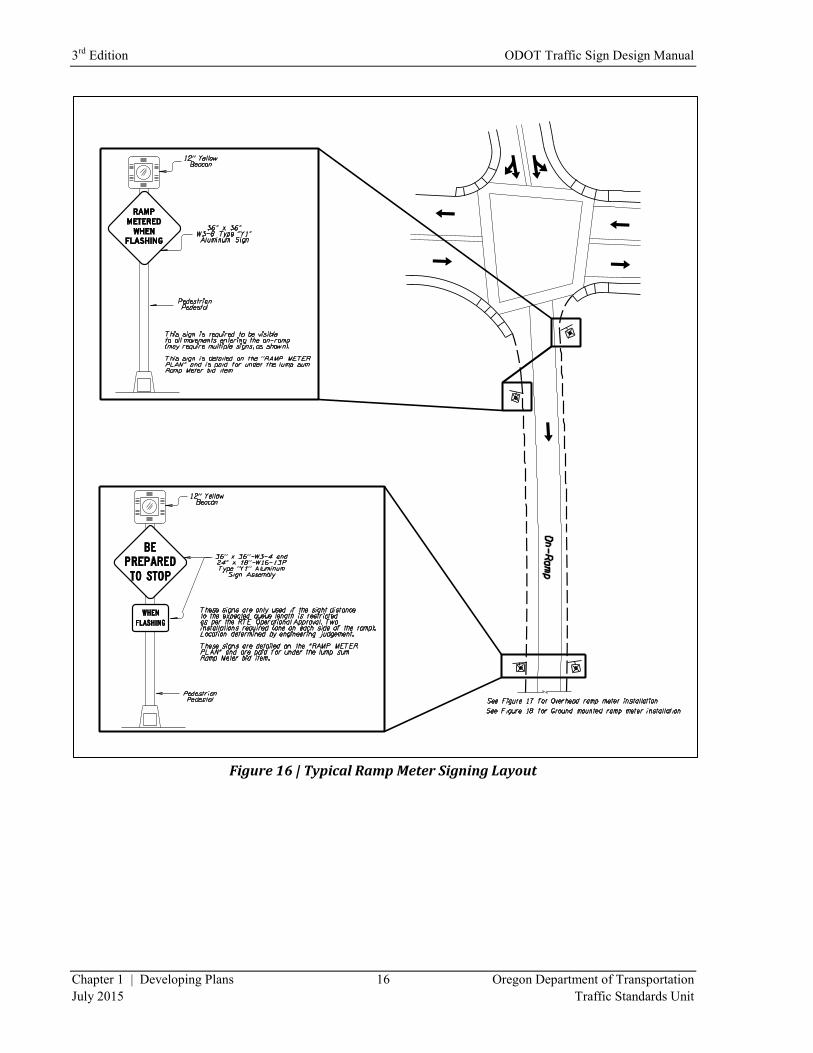
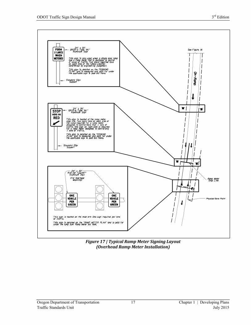
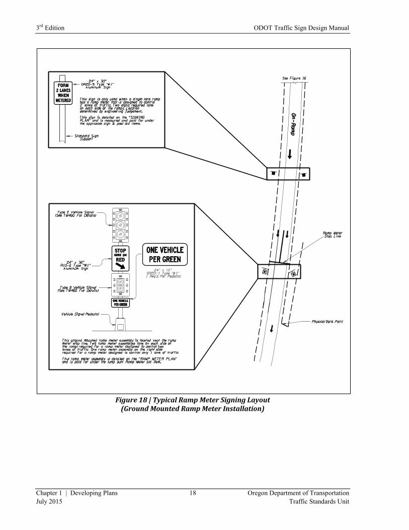
Figure 16 through Figure 18 show typical ramp meter sign layouts. The STOP HERE ON RED and
FORM 2 LANES WHEN METERED signs are paid for under the applicable sign and post bid items. All
other signs are detailed on the “Ramp Meter Plan” and paid for under the lump sum Ramp Meter bid item.
ODOT Traffic Sign Design Manual 3rd
Edition
Oregon Department of Transportation 11 Chapter 1 | Developing Plans
Traffic Standards Unit July 2015
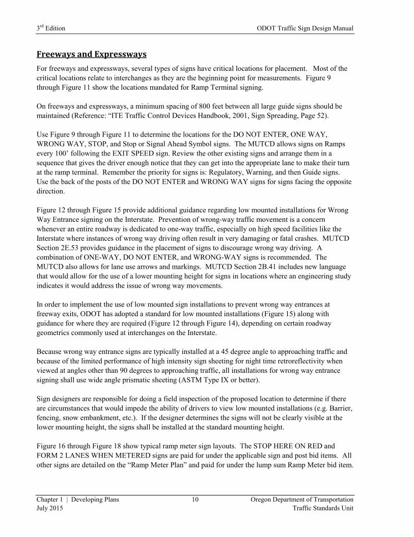
Figure 8 | Weigh Station Signing Interstate with Weigh-In-Motion
3rd
Edition ODOT Traffic Sign Design Manual
Chapter 1 | Developing Plans 12 Oregon Department of Transportation
July 2015 Traffic Standards Unit
Figure 9 | Regulatory Signing at Exit Ramp
(MUTCD Figure 2B-18, ref.)
Figure 10 | Typical Guide Signing at Exit Ramp

ODOT Traffic Sign Design Manual 3rd
Edition
Oregon Department of Transportation 13 Chapter 1 | Developing Plans
Traffic Standards Unit July 2015
Figure 11 | Typical Signing for Exit Ramp with Right Turn Lane
Figure 12 | Low Mount Signing – Standard Ramp Terminal
3rd
Edition ODOT Traffic Sign Design Manual
Chapter 1 | Developing Plans 14 Oregon Department of Transportation
July 2015 Traffic Standards Unit
Figure 13 | Enhanced Wrong Way Signing – Folded Diamond Ramp Terminal
Figure 14 | Low Mount Signing – Ramp Terminal with Concrete Island
ODOT Traffic Sign Design Manual 3rd
Edition
Oregon Department of Transportation 15 Chapter 1 | Developing Plans
Traffic Standards Unit July 2015
Figure 15 | Low Mount Sign Installations – Freeway Ramp Terminals
3rd
Edition ODOT Traffic Sign Design Manual
Chapter 1 | Developing Plans 16 Oregon Department of Transportation
July 2015 Traffic Standards Unit
Figure 16 | Typical Ramp Meter Signing Layout
ODOT Traffic Sign Design Manual 3rd
Edition
Oregon Department of Transportation 17 Chapter 1 | Developing Plans
Traffic Standards Unit July 2015
Figure 17 | Typical Ramp Meter Signing Layout
(Overhead Ramp Meter Installation)
3rd
Edition ODOT Traffic Sign Design Manual
Chapter 1 | Developing Plans 18 Oregon Department of Transportation
July 2015 Traffic Standards Unit
Figure 18 | Typical Ramp Meter Signing Layout
(Ground Mounted Ramp Meter Installation)
ODOT Traffic Sign Design Manual 3rd
Edition
Oregon Department of Transportation 19 Chapter 1 | Developing Plans
Traffic Standards Unit July 2015
Sign Spacing
Conventional Highways
Now is a good time to look at what you have on the plan sheets and look at the spacing between signs
both on the State Highway and the intersecting roads. Remember some of the Regulatory signs cannot be
moved from where they are placed. Warning signs should be placed using the “Guidelines for Advance
Placement of Warning Signs” listed in the MUTCD (Table 2C-4). Note these are guidelines, not
mandatory placement distances.
It is important that the warning sign placement gives the driver enough time to determine and take
corrective action before they get to the item being warned about. This does not mean that you put the sign
in at the distance shown on the chart just because it is on the chart. Visibility and applicability of the sign
is just as important. Warning sign legends with smaller letter size (less than 6”) or more than four words
might justify using a longer distance.
This leaves other signs subject to moving in order to obtain the proper spacing between the signs to make
them readable for the driver. This is also a good time to think about combining some of the signs on the
same support to reduce the number of sign installations on the roadway. Do not combine different types
of signs on the same post if you can avoid it. Regulatory and Warning signs should be installed on their
own posts.
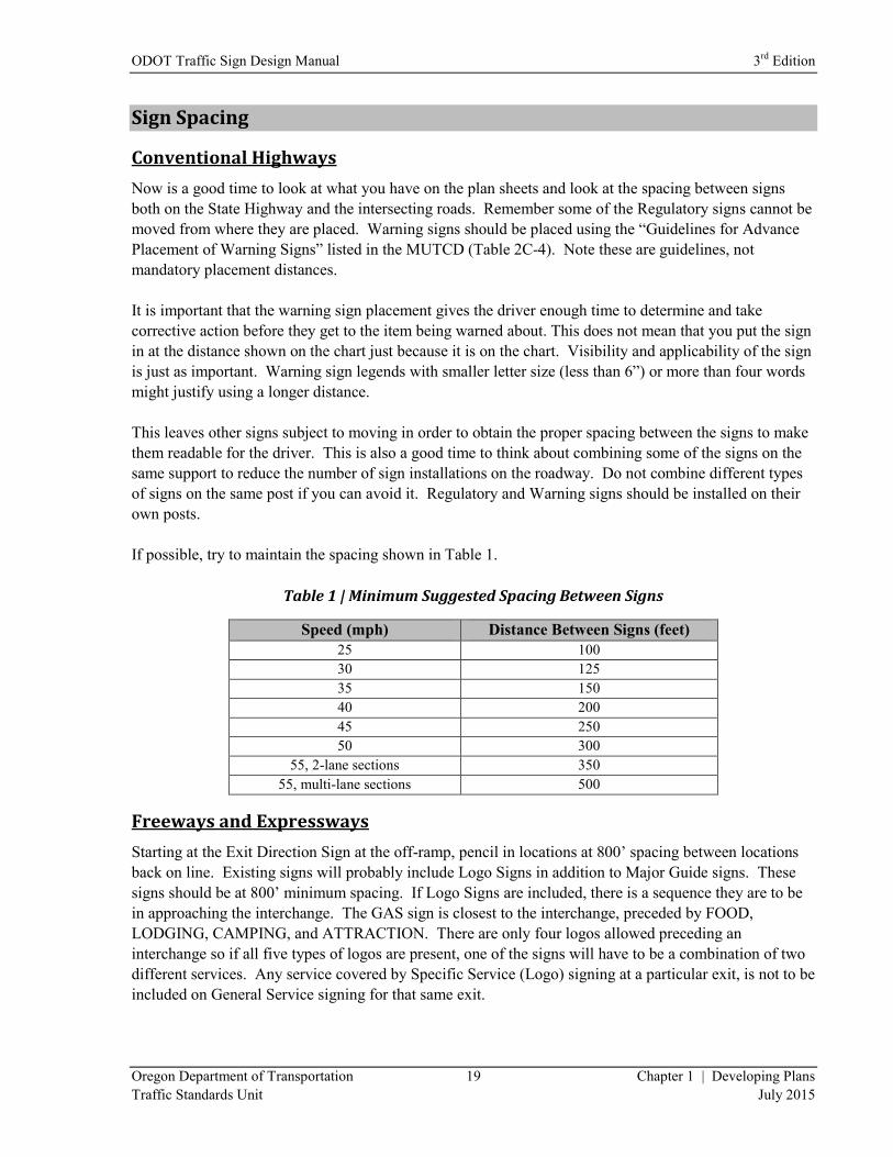
If possible, try to maintain the spacing shown in Table 1.
Table 1 | Minimum Suggested Spacing Between Signs
Speed (mph) Distance Between Signs (feet)
25 100
30 125
35 150
40 200
45 250
50 300
55, 2-lane sections 350
55, multi-lane sections 500
Freeways and Expressways
Starting at the Exit Direction Sign at the off-ramp, pencil in locations at 800’ spacing between locations
back on line. Existing signs will probably include Logo Signs in addition to Major Guide signs. These
signs should be at 800’ minimum spacing. If Logo Signs are included, there is a sequence they are to be
in approaching the interchange. The GAS sign is closest to the interchange, preceded by FOOD,
LODGING, CAMPING, and ATTRACTION. There are only four logos allowed preceding an
interchange so if all five types of logos are present, one of the signs will have to be a combination of two
different services. Any service covered by Specific Service (Logo) signing at a particular exit, is not to be
included on General Service signing for that same exit.
3rd
Edition ODOT Traffic Sign Design Manual
Chapter 1 | Developing Plans 20 Oregon Department of Transportation
July 2015 Traffic Standards Unit
Pencil in the major guide signs on the sign plan starting at the Exit Direction sign. Going back away from
the interchange, they would most likely be: Gas Logo, Food Logo, Supplemental Guide Sign, Lodging
Logo, Camping Logo, and Advance Guide Sign. Check to see if there is space available to install a 2
Mile Advance Directional sign if warranted. Usually, any interchange other than a minor one would
warrant a 2 Mile Advance Directional sign according to the MUTCD.
Sign Specific Needs and Guidance
After taking stock of the existing signs, consider new signing needs. These needs vary depending on the
type of project and the type of facility upon which it is located.
Curve Warning
Curve warning signs should not normally be used when the safe speed on the curve exceeds the posted
speed. Curve signs are optional when the safe speed on the curve is the same as the posted speed. Curve
warning signs are recommended when the safe speed on the curve is at least 5 MPH less than the posted
speed on the roadway. Curve warning signs with a speed rider are required when the safe speed on the
curve is at least 10 MPH less than the posted speed on the roadway.
The only sure way to check the safe speed on curves is with a ball bank indicator. If you are paving the
roadway with this project, the paving may change the super-elevation on the road changing the safe
speed. You can estimate the safe speed on a curve using the Comfort Speed Chart located in the Highway
Design Manual, Page 3-19. The Region Traffic personnel should ball-bank the curves after the project is
paved to determine if the speed riders (as designed) are correct.
The W1-1 or W1-3 turn warning signs are to be used when the Advisory Speed is 30 MPH or less. The
W1-2 or W1-4 curve warning signs are to be used when the Advisory Speed is more than 30 MPH.
The Large Arrow sign (W1-6) or chevron markers (W1-8) are required as a supplement to the curve or
turn warning signs when the safe speed on the curve is at least 15 MPH less than the posted speed. If
there are existing Large Arrow signs or chevron markers on the project, they should be replaced unless
there is a change in horizontal alignment. Existing signs of this type are an indication that there have
been problems in the past with run-off-the-road type of accidents in this area. Placement of these signs or
markers should be in conformance with the locations listed in the MUTCD (Sections 2C.09 and 2C.12).
Exit Direction / Advance Guide
The legend on the Exit Direction and the Advance Guide sign are required to be the same message
(MUTCD Section 2E.30). There is a limit of two destinations per guide sign. If there are more than two
destinations for the interchange, use a supplemental guide sign. Previous designs for these signs may
have a message such as “NEXT RIGHT” or “NEXT EXIT”. The MUTCD now requires the Exit Number
on the sign face or as an Exit Number sign placed over the guide sign (MUTCD Section 2E.31).
Intersection Signing
Typical intersection signing for cross-roads, T-intersections, and separated roadways is shown in the
MUTCD.
ODOT Traffic Sign Design Manual 3rd
Edition
Oregon Department of Transportation 21 Chapter 1 | Developing Plans
Traffic Standards Unit July 2015
Lane Reduction and Addition Transition
It is important to place lane reduction signing in accordance with the striping. See Figure 3 for example
layout.
Rural Left Turn Lane Refuge
See Figure 5 for example layout.
Milepost Markers
Milepost Markers are sometimes replaced as part of the signing plans. Check the location of the existing
installations. They are frequently in the wrong location and need to be moved.
Motorist Service
Motorist Service signs may include destinations such as State Police, City Police, Sheriff’s Office, DMV,
DEQ, Hospital, Rest Area, Rest Rooms, Visitors Information Center, Scenic Areas or Overlooks, etc.
These are general service signs maintained by ODOT (MUTCD Section 2I.02). These are replaced as
appropriate as part of standard sign plans.
These should not be confused with specific service signs maintained by the Oregon Travel Experience
(OTE). These signs are maintained by OTE. See section on Specific Service signs.
No-Parking Resolution
If you have any No-Parking Resolutions (See Appendix B “No Parking Resolution”), draw their locations
on the plan sheets. Draw (or describe) the type of restriction on the plan sheet for future reference. Some
NO PARKING signs may not be located according to the No-Parking Resolution and need to be moved.
Some of the NO PARKING signs may have been installed without any recorded resolution on file. NO
PARKING signs installed without a No-Parking Resolution should be removed.
Other Regulatory Signs
These include Lane Use Control signs, Turn Restriction, DO NOT PASS, KEEP RIGHT, DO NOT
ENTER, WRONG WAY, ONE-WAY, BEGIN RIGHT TURN LANE, YIELD TO BIKES, etc… In
general, these will be replaced in the existing location, but designers should be careful to make sure the
messages are still appropriate. Check changes in the pavement marking design that would require
relocation of these signs.
Physical Separation of Lanes
See Figure 6 for example layout.
Post Interchange
Where spacing between interchanges permits, place a route marker assembly (e.g. I-5 shield with
NORTH or SOUTH above it) 500 feet beyond the end of the acceleration lane, followed by:
1. SPEED LIMIT XX After 1000 feet
2. Mileage/Destination Sign After 1000 feet
3. EMERGENCY PARKING ONLY After 1000 feet
4. SLOWER TRAFFIC KEEP RIGHT After 1000 feet (not more often than once every 5 miles)
3rd
Edition ODOT Traffic Sign Design Manual
Chapter 1 | Developing Plans 22 Oregon Department of Transportation
July 2015 Traffic Standards Unit
Ramp Terminal
Review all Ramp Terminal signs and check for appropriate legends. Check the cross road for Jct. Signs,
Route Shield Assemblies (may be incorporated in the guide signs), lane use control signs, speed signs,
guide signs, etc. Check the on-ramps for lane drops, place the merge or add lane warning sign. Use
Figure 9 through Figure 11 for guidance on ramp terminal sign placement.
Road Names under Warning Signs
When road names are placed under warning signs in this fashion, the road name is to be a yellow
background with black legend for the warning sign rider. The road name sign should not exceed the
width of the main warning sign. Use guide signs to provide advance street name notice at locations where
no intersection or signal ahead warning signs are needed.
Route Signing
All State Highways have an official state route assigned to them, but not all of the State Highways have
the state routes signed. Route shield assemblies are required in certain circumstances, such as
intersections of two state highways, and the beginning of routes, etc. In the past, Route Shield
Assemblies were considered optional in many circumstances. The MUTCD makes route signing at the
beginning of State Highways mandatory. Many people navigate by using the Route shields so you should
include them whenever a change in direction is required.
The use of Route shield assemblies as trail blazers and confirmation signs is also critical to some drivers.
Route shields can be placed inside the Guide Signs, directions for doing that will be discussed later in
Chapter 2 (Designing Guide Signs).
Review the existing guide signs to ensure the existing legend is still appropriate for the project. The
legend size may need enlarging to meet current MUTCD standards; this will be discussed later in Chapter
2. Pencil in the locations and proposed text for all the guide signs. Advance guide signs on conventional
highways are encouraged where Right of Way permits their use.
School Speed Zones
Review the Speed Zone Order (See Appendix B “Speed Zone Orders”) for any school zone exceptions.
The School Speed Limit 20 zones are actually exceptions to the Speed Zone Order because the school
speed is different than the normal posted speed. The limits shown for the school speed exception are the
exact locations for placing the SCHOOL SPEED LIMIT 20 sign for traffic flowing that direction.
Directly across the road from the SCHOOL SPEED LIMIT 20 signs (for traffic flowing the other
direction), place an END SCHOOL SPEED LIMIT sign, or use an END SCHOOL ZONE sign for zones
posted with FINES HIGHER signs. Various school zone scenarios and their associated signing are
presented in ODOT’s Sign Policy & Guidelines (Chapter 7).
ODOT Traffic Sign Design Manual 3rd
Edition
Oregon Department of Transportation 23 Chapter 1 | Developing Plans
Traffic Standards Unit July 2015
The laws regarding signing for school zones were changed by the State Legislature in 2003 and 2005.
One of the changes was removing school speed zones from under ORS 811.105 as a “basic rule violation”
so all school speed zones are included under ORS 811.111 as “violating a speed limit”. In order to reflect
the new ORS language, sign designers shall use either the SHS R2-1 SPEED LIMIT 20 sign design as
part of the school speed limit assembly, the S5-1 SCHOOL/SPEED LIMIT 20/WHEN FLASHING sign,
or the OS5-5 SCHOOL/SPEED LIMIT 20 design from the Sign Policy and Guidelines when designing
plans for locations with speed limit signing in school zones.
The OR2-1 sign design from the Sign Policy and Guidelines will no longer be considered an acceptable
sign option for speed limit signing in school zones on State Highways. Existing SPEED 20 signs within
school zones should be changed to SPEED LIMIT 20 when they are due for normal maintenance
replacement or as part of construction projects.
Sign the school zone with the required School Advance Warning Assembly (S1-1). Refer to the Sign
Policy and Guidelines, Chapter 7, for their location. Oregon has taken exception to the location of the
signing in the MUTCD. The MUTCD recommends placement of the sign with respect to the school
grounds or school crossing, but the Oregon supplements require the placement based on the location of
the School Speed Limit Assembly (Oregon Supplements to MUTCD, Section 7B.15). For the School
Crosswalk Warning Assembly (S1-1) the use of the downward pointing arrow (W16-7p) is required
(MUTCD, Section 7B.12). The School Crosswalk Warning Assembly (S1-1) shall not be installed on
approaches controlled by a STOP sign (MUTCD, Section 7B.12).
Slow Moving Vehicle Turnouts
Slow moving vehicle turnouts are not commonly installed in Oregon; however, you may have to replace
existing signing as part of a project. See Figure 4 for the typical layout.
Specific Service (OTE Signs)
In addition to General Motorist Service signs installed by ODOT, there are other types of blue signs
installed by the Oregon Travel Experience (OTE). Logos are available for Gas, Food, Camping, Lodging,
and Tourist Attractions. Tourist Oriented Directional signs (TODS) are for any business that gets the
majority of their income from people who live outside the local area.
OTE signs are placed on ODOT Right of Way but actually belong to the OTE. These signs are usually
listed as “maintain and protect” as part of a project if possible. If the signs are impacted at all, notify
Oregon Travel Experience that a project will impact their signs. You can reach OTE at 503-378-4508 or
1-800-574-9397. If the widening of the road makes moving the Logo or TODS necessary, normally they
can be removed and reinstalled on the existing supports.
OTE may request new supports or the change in slope may require a new support. OTE needs to review
your Preliminary, Advance, and Final Plans. The Logo and TODS signs need to be maintained during
construction and the work zone traffic designer should be reminded to provide for them if necessary.
There are occasional brown TOD signs for historic districts, museums, or historic properties. The brown
signs are limited to three destination groups: Historical, Cultural, or Recreational. These signs can be
word messages or symbol signs or a combination of both words and symbols. Brown background signs
would include Historic Districts, Historic Properties, Historic Highways, Museums, Parks, Recreational
Areas, Fairgrounds, etc.
3rd
Edition ODOT Traffic Sign Design Manual
Chapter 1 | Developing Plans 24 Oregon Department of Transportation
July 2015 Traffic Standards Unit
Speed Zones
Review the Speed Zone Order(s) (See Appendix B “Speed Zone Orders”) which cover your particular
section of highway, pencil in the limits of the speed zone and place the appropriate speed sign at all
changes in speed. If there are major intersections between breaks in the speed zone, you should allow for
one speed sign each direction as close as possible to the intersection. This allows the driver to determine
the appropriate speed upon entering the roadway. You may notice the locations of the signs to be
installed are not the same as the existing speed signs. This is not unusual as many speed zones have been
incorrectly signed.
The location of the SPEED XX or SPEED LIMIT XX signs should be located at the points of change
from one speed limit to another (Section 2B.13 MUTCD) according to the Speed Zone Order. SPEED
LIMIT XX signs are to be used for all applications on the interstate, in school zones or within city limits.
The SPEED XX signs are to be used for all applications other than these. If the location in the Speed
Zone Order is not practical, an adjustment of up to 100 feet is permissible. If the location is not suitable
for appropriate signing, the Region Traffic Section should be contacted to discuss the possibility of
having the Speed Zone Order re-evaluated.
See Figure 2 for example of typical speed zone signing.
State Supplied Signs
Many projects will include signs with unique graphic designs such as Scenic Byway or Tour Route signs,
State Parks Shields (D-434) (supplied by state parks), and others not traditionally fabricated by private
sign companies. Whenever these signs are needed, it may make sense for them to be designated state-
supplied so they do not enter into the bid. If this is the desire, then the subject signs would be noted in the
plans as “state supplied”. Money is then put into the contract for these signs to be purchased later, during
construction, from the ODOT Sign Shop, State Parks or other appropriate source as an anticipated item.
Anticipated items will be discussed in greater detail in Chapter 6 (Anticipated Items).
Stop Signs
Locate all the STOP sign installations on the plan sheets. Almost all of the state highways are considered
to be through highways. This means the highway has priority over intersecting roads except in those
locations where the intersecting roadway has a larger volume or a safety issue dealing with alignment has
been identified. You can assume (unless the existing signs show otherwise) all roads leading into the
State Highway should have a STOP sign (of course, this does not apply to signalized intersections).
Any STOP sign application on the State Highway that stops traffic traveling on the State Highway
requires approval from the State Traffic Engineer (ODOT Traffic Manual, Section 5.2.1.1). Decisions for
STOP sign applications on cross streets that are not State Highways are done by the Region Traffic
Manager/Engineer (ODOT Traffic Manual, Section 5.2.1.2).
Private approaches may sometimes be signed on State Highway Right of Way due to visibility problems.
There is a Policy on allowing these signs (see page 5-10 in the Sign Policy and Guidelines). Private
businesses are not allowed to place STOP signs and other traffic control devices on State Highway Right
of Way.

ODOT Traffic Sign Design Manual 3rd
Edition
Oregon Department of Transportation 25 Chapter 1 | Developing Plans
Traffic Standards Unit July 2015
The standard STOP sign size listed is 36” for any road 30mph or greater. This would also be the size of
the STOP signs on any cross street that intersects on a road 30 mph or greater. Even if the cross street is
25 mph or lower, the STOP sign should be a 36” sign because of the impact to the traffic on the faster
highway.
Stop Ahead / Signal Ahead
Check the alignment of the roads entering the State Highway for sufficient safe stopping sight distance.
Place Stop Ahead symbol signs if the stopping sight distance is lacking. If a new signal is being installed
as part of the project, a Signal Ahead symbol sign should be considered both on the main line and cross
streets. If the new signal is in close proximity to other signals, a Signal Ahead Symbol sign may not be
necessary.
Street Name
Install street name signs for highway and side streets if the highway has a name. If the highway does not
have a name, install route shield assemblies at all the major road connections. Place street name signs on
both sides of the post above the STOP sign. At T-intersections, place street name signs (for the highway
name) on both sides of the STOP sign post above the side street name signs. At cross street intersections,
the street name signs for the highway only need to be on the highway side of the STOP sign post.
Street name signs mounted on traffic signal mast arms shall be shown and detailed on the Signing Plans,
but only referenced on the Signal Plans. Since the signs are shown in the Signing Plans, they need to be
covered under the bid item for the specific sign type. These signs shall not be paid for as part of the lump
sum for signal installation bid item.
Weigh Station
Typical signing layouts for weigh stations off-interstate and those on the interstate with weigh-in-motion
are shown in Figure 7 and Figure 8, respectively.

3rd
Edition ODOT Traffic Sign Design Manual
Chapter 1 | Developing Plans 26 Oregon Department of Transportation
July 2015 Traffic Standards Unit
(This page intentionally left blank.)
Chapter 2
Designing Signs
ODOT Traffic Sign Design Manual
3rd Edition
3rd
Edition ODOT Traffic Sign Design Manual
Chapter 3 | Designing Supports 28 Oregon Department of Transportation
July 2015 Traffic Standards Unit
2 | Designing Signs
Choosing Substrate and Sheeting Types
A typical road sign consists of three components: substrate, sign sheeting, and sign legend. This chapter
discusses the common construction and materials involved in the construction of road signs.
Sign Substrates
ODOT uses sheet aluminum as our first choice of sign substrate material. However there are situations
where sheet aluminum is not the best choice for sign substrate. The other two materials ODOT may use
for permanent sign substrate are extruded aluminum and High Density Overlay (HDO) plywood. All
three of the signs substrate materials are recyclable.
There are numerous types of substrate for road signs that have been used over the years and new products
are being introduced every year. This chapter will deal with the current substrates being used in Oregon.
The overall dimensions of a sign will often help determine the appropriate substrate material for
fabrication. Section 00940 of Oregon’s Standard Specifications offers size guidelines and limitations for
the various sign substrate materials used on our highway system.
Sheet Aluminum
Sheet aluminum is ODOT’s first choice of sign substrate anywhere. It has a smooth flat surface and
comes in a variety of precut sizes to match most standard sized signs. The thickness of the aluminum
is increased as the size increases to maintain the strength of the sign. Sheet aluminum can also be
purchased in sheets just like plywood. The Oregon Standard Specifications lists the allowable
thickness for the size of sign and also lists the acceptable types of aluminum sheeting (ODOT
Specification 02910.10). Using something other than the specified type of aluminum sheeting may
result in failed substrate.
Sheet aluminum substrate should not be specified in high wind areas or snow plow areas since the
aluminum does not resist bending well. In rural areas with a history of gunshot vandalism, HDO
plywood substrate should be considered because unlike aluminum, the plywood can often sustain
gunshot damage and still remain readable.
Signs designed using sheet aluminum should be designed in width and height that increase in 3”
increments (the same as plywood signs). The maximum size of sheet aluminum signs is 4’ x 5’, due
to its tendency to deform or sustain wind damage when used for signs larger than this. Many other
states have limited normal sheet aluminum sign use to this dimension for the same reason. Sheet
Aluminum overlays on Extruded Panel signs are not limited in size since the Extruded Aluminum
panels support the sheet aluminum. Mast arm mounted street name signs are not limited in size since
the signal mast arm helps to support the sheet aluminum.
ODOT Traffic Sign Design Manual 3rd
Edition
Oregon Department of Transportation 29 Chapter 3 | Designing Supports
Traffic Standards Unit July 2015
In some locations of the state, designers must include painting the backs of aluminum signs to blend
in with the environment. When required to do this, there is a Special Provision in Section 00940 that
should be used for this purpose and it automatically calls up Section 00937 that has the painting
specifications. Different locations may call for different colors of paint. Most of these places will
also require you to paint the metal sign supports as well.
Extruded Aluminum Panels
Extruded aluminum panels are composed of pre-formed structural shapes bolted together to create the
sign substrate. The shape is shown on Oregon Standard Drawing Number TM675 in the upper left
corner. The extrusions come in 6” and 12” tall panels up to 34’ in length. Each extrusion is covered
with sign sheeting prior to bolting the panels together to form the sign. Normally, the border, text,
route shields, etc. are placed on a thin aluminum background and then pop-riveted to the preformed
sign background. Signs designed using aluminum extrusions should be designed in width and height
that increase in 6” increments. Due to size restrictions for plywood and sheet aluminum, extruded
aluminum panels must be used for all signs larger than 4’ x 8’. The nature of their fabrication
requires their fastening to the support by means of post clips rather than bolts. Many of the steel
signs supports (Chapter 3) such as triangular base breakaway posts, multi-post breakaway supports,
exit number sign mounts and signal pole mounts are designed specifically for fastening by clips.
Where such supports are used, extruded panel signs (regardless of size) should be specified.
Occasionally, a legend can be applied directly to the extruded panel if the legend does not span from
one extrusion to the other. Direct applied legend when applied to two extrusions will accumulate dirt
and other materials where the two extrusions meet causing a dirt pocket that will retain moisture;
when this freezes, the sheeting can be damaged by the expanding mass-it also looks very unsightly.
High Density Overlay (HDO) Plywood
HDO plywood is the only plywood allowed for permanent signs on ODOT projects. HDO plywood
has a very smooth surface similar to a Formica cabinet face. No primer is required between the face
of plywood and the sign sheeting. HDO plywood does not have the surface blemishes found in the
MDO plywood due to the thicker overlay applied when the plywood was made. HDO plywood is
very rigid and is an excellent substrate for signs that must withstand a lot of wind pressure. This
substrate should be used in Snow Zone areas because it holds up very well against the snow blower
and snow plow damage. It should also be used in rural areas where there is a history of sign damage
from gunshot vandalism, because the plywood can often sustain gunshot damage and remain
readable.
This product is available in 4’ x 8’ sheets (maximum size allowed for plywood substrate signs) and is
cut to the size needed for a particular sign. ODOT uses ¾-inch HDO plywood. If the project you are
designing is for someone other than ODOT, you might want to check on the thickness they use.
Signs designed using HDO or MDO plywood should be designed in width and height that increase by
3” increments (e.g. 4’-6” x 3’-9”).
3rd
Edition ODOT Traffic Sign Design Manual
Chapter 3 | Designing Supports 30 Oregon Department of Transportation
July 2015 Traffic Standards Unit
Medium Density Overlay (MDO) Plywood
MDO plywood formerly was the standard for almost all the plywood signs in Oregon. Some time
ago, there was a problem with the primer (required on the MDO plywood for adhesion to the sign
sheeting) resulting in massive failures of sign faces throughout the state. ODOT was given no relief
by the manufacturers for the signs that had to be replaced when the primer failed. As a result of this,
MDO plywood is now allowed on ODOT contracts for temporary signing only.
MDO plywood does have surface blemishes (plugs) that sometimes distract from the smooth finish of
the finished sign face. This plywood is very rigid and is an excellent substrate for signs that must
withstand a lot of wind pressure. This product is available in 4’ x 8’ sheets and is cut to the size
needed for a particular sign.
Other Substrates
ODOT has tried using plastic and fiberglass substrates on signs in the past without much success.
Different substrates will likely be available in the future that will fulfill ODOT requirements for a
dependable long lasting sign substrate.
If you are designing a project for a local government and they want to use another substrate, you will
need to include a detail and specifications of what the substrate looks like and the materials
specification for each type.
Sign Sheeting
There are numerous types of sign sheeting available and each type has its advantages and disadvantages,
so it is very important to specify which type of sheeting to use on each sign you have designed.
ASTM Type I
This sheeting is also called Engineer Grade or Scotchlite. This is the lowest grade of reflective
sheeting available and has been used for many decades. It may not have a manufacturer’s warranty,
and does not reflect a great deal of light, but it is the cheapest of the reflective sheetings. This
sheeting is not used on the State Highway System.
ASTM Type II
This sheeting is also known as Super Engineering Grade. This sheeting is not used in Oregon so it
does not show up in the Oregon Specifications. Other states have used this sheeting as it is about
twice as bright as Engineer Grade Sheeting. This sheeting is not used on the State Highway System.
ASTM Type III
This sheeting is also known as High Intensity. On State Highways, this is the minimum reflective
sheeting allowed and also the most used sheeting. Almost all ground mounted signs will use Type III
sheeting for backgrounds and almost all of the legends. Type III sheeting is also used for background
sheeting on overhead guide signs. This sheeting is warranted for 10 years from the manufacturer.
ASTM Type IV
This sheeting is a multi-layer sheeting, sometimes called prismatic sheeting. Performance of Type IV
sheeting is similar to the performance of Type III sheeting.
ODOT Traffic Sign Design Manual 3rd
Edition
Oregon Department of Transportation 31 Chapter 3 | Designing Supports
Traffic Standards Unit July 2015
ASTM Type V
This sheeting is not normally used for signs. It is used for delineators and raised pavement markers.
ASTM Type VI
This sheeting is for roll-up signs, traffic cone collars, and post bands. There is a QPL listing for this
type of sheeting.
ASTM Type VII
This is a highly retroreflective sheeting previously used in overhead sign installations and was only
warranted for use on aluminum substrates. Its use on our State Highway System was discontinued as
newer, improved sheeting types became available. This type of sheeting no longer appears on the
QPL.
ASTM Type VIII
This sheeting is similar to types VII but has a narrower band of retroreflectivity. This type of
sheeting has not been used in Oregon for permanent signing.
ASTM Type IX
This sheeting is similar to type VII but has a much wider angularity and is not quite as bright as the
type VII. It can be used for ground mounted signs but should be reserved for places where high-
impact is needed. It is more commonly used for background and/or legend on overhead mounted
signs. Viewing distance on this sheeting is up to 800 feet away. The warranty on this sheeting is 12
years. It also comes in fluorescent colors; yellow, yellow-green, and orange. In the fluorescent
colors, a ten year warranty applies.
ASTM Type X
This sheeting is similar to types VII but has a narrower band of retroreflectivity. This type of
sheeting has not been used in Oregon for permanent signing.
Non-Reflective Sheeting
Since the MUTCD requires all signs to be retroreflective and to be the same color at night as during
the day, the use of non-reflective sheeting has become extinct except for black. Black sheeting comes
in rolls or as a “tape” that is the common width of most borders. The use of black in Oregon is
limited to legends for regulatory and warning signs.
Electronic Cutable Film (EC Film)
This is a semi-transparent film placed over the underlying sign sheeting to change the color of the
sign sheeting. It is an alternate to applying another layer of sheeting (usually for legend, but could be
a background) in the manufacturing process. Usually, this is not an item you would specify when
building a sign plan but it is something of which you should be aware. There is also a black non-
reflective EC Film used in lieu of the standard black sheeting mentioned above.
3rd
Edition ODOT Traffic Sign Design Manual
Chapter 3 | Designing Supports 32 Oregon Department of Transportation
July 2015 Traffic Standards Unit
The Sign and Post Data Table sheet provides the sign manufacturer precise information on the
construction of the sign specified (See Chapter 4 “Sign and Post Data Tables”). This doesn’t mean there
isn’t another way the sign can be built and still perform to ODOT standards. One option is the use of
Electronic Cuttable Film (EC Film) not usually listed as a construction method but meets ODOT
specifications and performs very well.
The EC Film is a semi-transparent film that allows light to reflect back through to create the colors
required on the sign. It is very cost effective for unusual designs (such as the Tsunami Series, Oregon
Trail, Lewis & Clark, etc.) since it replaces the silk screening method. For sign shops that do not silk
screen, EC Film is a very practical method of building signs. EC Film is also resistant to vandals trying
to remove letters from the legend as the film will come off in tiny pieces.
Sign Sheeting Identification
You can view or download a two page document illustrating the identification marks of several
manufacturers of the different types of sheeting. This is valuable information for those of you who also
will be called upon to identify the materials. It can be accessed at:
http://safety.fhwa.dot.gov/roadway_dept/night_visib/sign_visib/sheetguide/.
Sign Legend
Once the sign sheeting has been applied to the sign substrate, the legend can be applied to the sign face in
three different fashions: direct applied, demountable legend, or silk-screening.
Direct Applied
Sign sheeting or black tape is cut into letters, borders or whatever else is called for as a legend. Most
sheeting or border tape has a removable backing that can be removed and applied over the
background sheeting to form the legend on the sign.
Demountable Legend
Sign sheeting specified for the legend is applied to a thin aluminum and then the letters are cut out
with a die (or cut with a router). The legend is then laid out on the sign as specified and pop-riveted
to the sign. The advantage of making signs this way is that the legend can be changed on the sign
after it is made or erected. This method is required for extruded panel signs if any of the legend on
the sign overlaps or crosses the joint between extrusions. This legend is often referred to as
“Removable Legend” since the legend can be removed from the sign by drilling out the rivets.
Silk Screening
Smaller signs can have a legend applied by the silk-screening process similar to the way that t-shirts
are screen printed. This process is used for many of the standard signs in an effort to keep
manufacturing costs to a minimum.
ODOT Traffic Sign Design Manual 3rd
Edition
Oregon Department of Transportation 33 Chapter 3 | Designing Supports
Traffic Standards Unit July 2015
Designing Regulatory and Warning Signs
There are rules for designing signs that come from several different sources including the MUTCD, some
are industry standards. The Standard Highway Signs manual shows all of the sign designs for standard
regulatory and warning signs shown in the MUTCD. If a standard sign is from the MUTCD, the sign
design is already completed for you, but you still must determine the appropriate size to install.
The sizes of standard signs shown for regulatory and warning purposes in the MUTCD (see Tables 2B-1
and 2C-2) vary by highway classification, with larger sizes called for on the wider, higher speed
classifications such as freeways and expressways. In many cases ODOT has determined to use larger
minimum standard sizes than what is shown in these MUTCD tables. As a result we have created our
own standard size chart for regulatory and warning signs, intended to supplement the MUTCD tables.
ODOT’s chart is in Appendix D of this publication. Sign sizes for use on our state highway system are to
be determined by using this chart. For those regulatory and warning signs not found in Appendix D, sizes
are to be determined from use of the MUTCD charts.
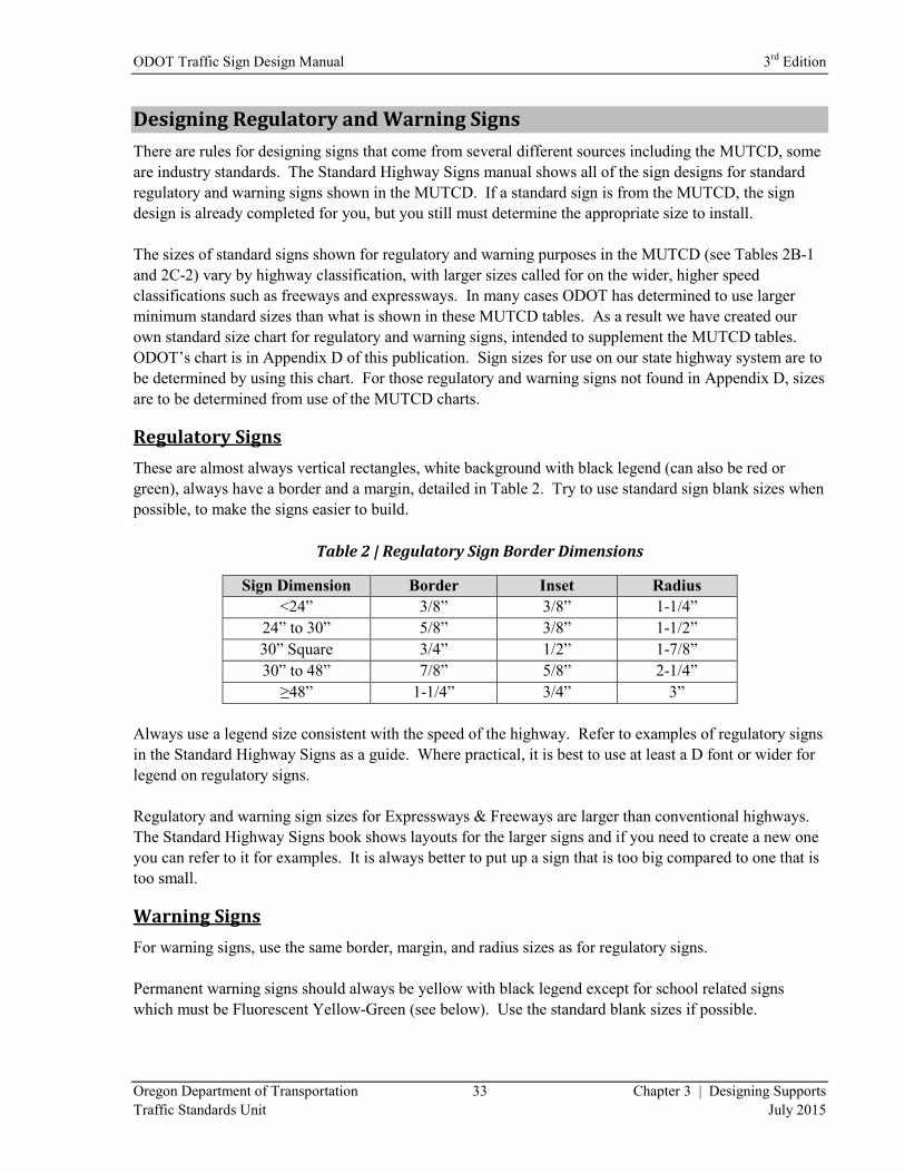
Regulatory Signs
These are almost always vertical rectangles, white background with black legend (can also be red or
green), always have a border and a margin, detailed in Table 2. Try to use standard sign blank sizes when
possible, to make the signs easier to build.
Table 2 | Regulatory Sign Border Dimensions
Sign Dimension Border Inset Radius
<24” 3/8” 3/8” 1-1/4”
24” to 30” 5/8” 3/8” 1-1/2”
30” Square 3/4” 1/2” 1-7/8”
30” to 48” 7/8” 5/8” 2-1/4”
≥48” 1-1/4” 3/4” 3”
Always use a legend size consistent with the speed of the highway. Refer to examples of regulatory signs
in the Standard Highway Signs as a guide. Where practical, it is best to use at least a D font or wider for
legend on regulatory signs.
Regulatory and warning sign sizes for Expressways & Freeways are larger than conventional highways.
The Standard Highway Signs book shows layouts for the larger signs and if you need to create a new one
you can refer to it for examples. It is always better to put up a sign that is too big compared to one that is
too small.
Warning Signs
For warning signs, use the same border, margin, and radius sizes as for regulatory signs.
Permanent warning signs should always be yellow with black legend except for school related signs
which must be Fluorescent Yellow-Green (see below). Use the standard blank sizes if possible.
3rd
Edition ODOT Traffic Sign Design Manual
Chapter 3 | Designing Supports 34 Oregon Department of Transportation
July 2015 Traffic Standards Unit
Always use a legend size consistent with the speed of the highway. Refer to examples of warning signs in
the Standard Highway Signs as a guide. Where practical, it is best to use at least a D font or wider for
legends on warning signs. It is always better to put up a sign that is too big compared to one that is too
small.
Minimum sign size for warning signs on the State Highway System is 36”.
Lane Drops (EXIT ONLY)
For lane drop situations (EXIT ONLY), often a yellow overlay is placed on an overhead guide sign.
The yellow overlay is typically a horizontal rectangle instead of a diamond. Other situations may also
require a horizontal rectangle instead of a diamond.
Fluorescent Yellow-Green
ODOT policy is to reserve the use of fluorescent yellow-green sign sheeting for school zone signing
on state highways including the “SCHOOL” portion of the School Speed Limit (S5-1) sign and any
supplemental plaques used in association with these warning signs. Pedestrian and/or Bicycle
warning signs should use the standard yellow color. Fluorescent yellow sign sheeting may be used
for pedestrian and/or bicycle crossing signs if there is a need to call extra attention to a particular
crossing.
The Region Traffic Engineer may allow the use of fluorescent yellow-green for pedestrian/bicycle
warning signs on a state highway if the requesting jurisdiction can demonstrate an existing systematic
approach to pedestrian signing which includes the fluorescent yellow-green sign background.
However, other treatments must be considered before choosing fluorescent yellow-green sign
sheeting (e.g. curb extensions, pedestrian refuge islands, Rapid Flash Beacons, etc.). The mixing of
standard yellow and fluorescent yellow-green backgrounds for pedestrian/bicycle signs within a
selected site area should be avoided.
Designing Guide Signs
Legend Sizes and Spacing
Lower-case letters following an initial upper-case letter are the standard primary legend style
(destinations) to be used on guide signs. Other secondary legend (directional, guiding) is to consist
entirely of upper-case letters. Legend sizes are typically referred to by the upper-case letter size. The
lower-case value will always be 75% of the upper-case value. For example, 8” legend refers to 8” upper-
case along with 6” lower-case, where needed.
The MUTCD allows the use of 4” legend for principal legend on guide signs where the posted speed of
the highway is 25 MPH or less (MUTCD, Section 2D.06). On the State Highway System, the smallest
legend for principal legend on guide signs is usually 5”. The exceptions to this are Adopt-A-Hwy signs
and riders, Historic Trail Riders, and other riders where the main message is a symbol sign (such as
recreational symbol).
ODOT Traffic Sign Design Manual 3rd
Edition
Oregon Department of Transportation 35 Chapter 3 | Designing Supports
Traffic Standards Unit July 2015
The use of 6” legend is required for principal legend on guide signs where the posted speed of the
highway is over 25 MPH. The majority of guide signs on conventional highways use a 6-inch C legend.
The use of D or wider fonts is a judgment call for the designer. Wider fonts make the signs easier to read
but it also makes the sign wider. When a sign width exceeds the maximum permitted for a single post,
wider fonts are sometimes used to increase the size of the guide sign to the minimum required for
multiple posts.
The MUTCD recommends the use of 8” legend where the highway is a multi-lane, high-speed facility
(MUTCD, Section 2D.43). Larger legend is also warranted for overhead sign locations such as signs
mounted on a signal pole, signs viewed from a long distance, or critical signs.
The use of 10”C, 8”-6”EM, or larger can also be used on the multi-lane, high-speed highways. You
should always make sure that the size of legend is consistent with the speeds and lane widths on the
highway. It is always better to put up a sign that is too big compared to one that is too small.
The MUTCD recommends the use of 12” legend for overhead street name signs (Section 2D.43).
Due to the higher speeds and volumes associated with Expressways & Freeways, the legend on guide
signs are larger than on conventional highways. The MUTCD has tables (Tables 2E-2 through 2E-5)
outlining the minimum legend size used on these facilities. The tables apply to any highway (or portion
of a highway) built to Expressway or Freeway standards.
When using Tables 2E-2 through 2E-5, determine the interchange classification (from MUTCD Section
2E.32) for the design. In most cases, it will be Major, Category B or an Intermediate. The numbers listed
in the tables are for an EM font since that is the standard for guide signs on Expressway & Freeways
(MUTCD, Section 2E.14).
The tables are broken up into sections so each part of the sign has a specified letter or numeral height, or
specific dimensions. Use the correct column for the sign you are designing. The principal legend size of
Category A and B signs under the Major category call for 20”-15” legend for ground mounted signs. The
principal legend for Overhead signs is 16”-12” legend.
When designing guide signs, the width of the sign is determined by the legend plus the outside (lateral)
spacing that normally includes the border. Outside spacing is required on any sign to make them more
readable. The ideal lateral clearance is usually one letter height from the side of the sign to the end of the
legend, but may be as little as one half the letter height (ODOT Standard Drawings TM223 and TM224).
The average of the upper and lower case letters should be used for the vertical clearance from the legend
to the top (or bottom) of the sign. The spacing between lines of legend (vertically) ideally would be about
¾ of the legend height. It usually varies between ½ and 1 letter height.
Typical layouts for guide signs can be seen on Oregon Standard Drawings TM223 and TM224, the
Standard Highway Signs book, and in the Sign Policy and Guidelines.
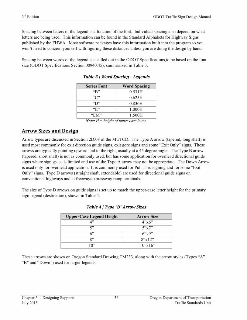
3rd
Edition ODOT Traffic Sign Design Manual
Chapter 3 | Designing Supports 36 Oregon Department of Transportation
July 2015 Traffic Standards Unit
Spacing between letters of the legend is a function of the font. Individual spacing also depend on what
letters are being used. This information can be found in the Standard Alphabets for Highway Signs
published by the FHWA. Most software packages have this information built into the program so you
won’t need to concern yourself with figuring these distances unless you are doing the design by hand.
Spacing between words of the legend is a called out in the ODOT Specifications to be based on the font
size (ODOT Specifications Section 00940.45), summarized in Table 3.
Table 3 | Word Spacing – Legends
Series Font Word Spacing
“B” 0.531H
“C” 0.625H
“D” 0.836H
“E” 1.000H
“EM” 1.500H
Note: H = height of upper case letter.
Arrow Sizes and Design
Arrow types are discussed in Section 2D.08 of the MUTCD. The Type A arrow (tapered, long shaft) is
used most commonly for exit direction guide signs, exit gore signs and some “Exit Only” signs. These
arrows are typically pointing upward and to the right, usually at a 45 degree angle. The Type B arrow
(tapered, short shaft) is not as commonly used, but has some application for overhead directional guide
signs where sign space is limited and use of the Type A arrow may not be appropriate. The Down Arrow
is used only for overhead application. It is commonly used for Pull Thru signing and for some “Exit
Only” signs. Type D arrows (straight shaft, extendable) are used for directional guide signs on
conventional highways and at freeway/expressway ramp terminals.
The size of Type D arrows on guide signs is set up to match the upper-case letter height for the primary
sign legend (destination), shown in Table 4.
Table 4 | Type “D” Arrow Sizes
Upper-Case Legend Height Arrow Size
4” 4”x6”
5” 5”x7”
6” 6”x9”
8” 8”x12”
10” 10”x16”
These arrows are shown on Oregon Standard Drawing TM233, along with the arrow styles (Types “A”,
“B” and “Down”) used for larger legends.
ODOT Traffic Sign Design Manual 3rd
Edition
Oregon Department of Transportation 37 Chapter 3 | Designing Supports
Traffic Standards Unit July 2015
The Type “D” arrows have a straight (non-tapered) shaft. Therefore, their length can be increased to
“balance” the sign. Sometimes when you have the sign designed, the arrow will look too small. If the
arrow is placed horizontally at the bottom of the sign, increase the arrow length to ½ the width of the sign
to make it easier to read.
If you are using a single arrow at the side of a two line legend, you might want to make the arrow longer
or increase the arrow to the next legend size to improve the readability of the sign.
Hook arrows (we tend to use a straight shaft version similar to Type D, instead of the Type C arrow
shown in MUTCD) are used for advance sign placement where you want the driver to turn at the next
intersection instead of the place where the sign is installed.
There is a hierarchy in the placement of arrows as they appear on a destination sign (Section 2D.37
MUTCD). Destinations that are straight ahead are listed at the top the top of the sign with the “up” arrow.
Below that would be any destinations to the left with the arrow pointing left, followed by any destinations
to the right with the arrow pointing right. All destinations in a given direction shall have one directional
arrow.
Design Layout
Separate destinations with a horizontal divider line all the way across the sign, to show groups of
destinations in a particular direction. Shorter horizontal lines on the guide sign face can be used to
highlight a section of the legend, or separate lines of legend if needed for clarity.
The number of destinations on a guide sign should be based on the driver’s ability to read the entire
message and still safely concentrate on the task of driving. Large amounts of legend should be reserved
for locations where the driver is stopped while reading the sign. If you have a lot of information for the
driver, consider making two signs with less legend and spacing them apart so the driver has ample time to
react to each one.
Advance guide signs on conventional highways are preferable, but not always possible due to right of
way constraints. When designing these signs, include a positive guidance message such as: “NEXT
RIGHT”, “LEFT ½ MILE”, etc… This gives the driver more information that they can use to make
better decisions.
Route shield assemblies are often required since the MUTCD requires their use where the highway has a
route number. All State Highways now have a route number assigned to them but not all of them have
been signed yet. For single installations, the assemblies are placed on a single support. When placing the
route shield assemblies in conjunction with guide signs, either place them on the guide sign face or attach
the assemblies underneath the guide sign. The standard size for a route shield is 24” when used by itself;
you can use smaller shields when you place them on the guide sign. The 18” version is the smallest and
should only be used when you are in an urban area using 6” legend on the guide sign. Use a 24” shield
when you use 8” legend.

3rd
Edition ODOT Traffic Sign Design Manual
Chapter 3 | Designing Supports 38 Oregon Department of Transportation
July 2015 Traffic Standards Unit
Freeway and Expressway Design
Legends on all overhead guide signs shall be ASTM Type IX retroreflective sheeting. All “EXIT ONLY”
panels on overhead guide signs shall be ASTM Type IX and utilize Fluorescent Yellow retroreflective
sheeting, with Black, non-reflective legend.
Guide signs for interchanges may have no more than two destinations on the Advance Guide signs and
Exit Direction signs, and the destinations have to match on these signs. One supplemental sign with a
maximum of two destinations is allowed per interchange.
Exit number panels are to be mounted flush with the right side of the guide sign for right exits. Exit
number panels for left exits are mounted flush with the left side of the guide sign. Standard exit panel
sizes for Oregon are different than the standards shown in MUTCD Table 2E-1. Our standards can be
found in Oregon Standard Drawing TM225. The Oregon version of these signs is considerably narrower
than the MUTCD version, yet it still satisfies MUTCD guidelines for margin spacing (Sec. 2E.15) on the
sides. The ODOT version eliminates excess “green” space that would otherwise make these panels
unnecessarily large. Exit numbers on Supplemental signs can have the exit number as part of the legend,
or as an Exit number panel.
Border width for guide signs depends on the legend size, not the sign size. Signs having a legend in
upper and lower case letters with 10 2/3” or smaller upper case letters and signs having a 12” or smaller
all capital lettered legend shall have a 1” border. All signs with a legend larger than as specified above
shall have a 2” border. The exceptions to this would be any standard sign included in the FHWA
Standard Highway Signs book.
There are sample sign designs shown on Oregon Standard Drawing TM224. Exit Gore sign standards are
shown on Oregon Standard Drawing TM225 and are consistent with the standards shown in MUTCD
Table 2E-1.
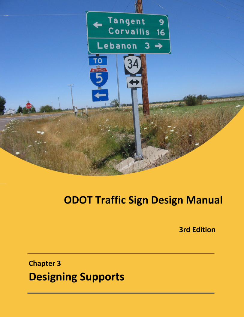
ODOT Traffic Sign Design Manual 3rd
Edition
Oregon Department of Transportation 39 Chapter 3 | Designing Supports
Traffic Standards Unit July 2015
ODOT Traffic Sign Design Manual
Chapter 3
Designing Supports
3rd Edition
3rd
Edition ODOT Traffic Sign Design Manual
Chapter 3 | Designing Supports 40 Oregon Department of Transportation
July 2015 Traffic Standards Unit
3 | Designing Supports
Choosing a Support Type
There are numerous types of sign supports available that the designer specifies for each sign on the
project. This chapter describes the various sign supports that are used on ODOT projects. The designer
should always contact the District Sign Supervisor/Coordinator when deciding which post material to
specify for the smaller sign supports.
Sign supports used on the State Highway System must have breakaway features when used inside the
clear zone and should have breakaway features when located outside the clear zone. Sign supports
without breakaway features are required to be shielded from traffic (when inside the clear zone) with a
concrete barrier, guard rail, or some other device to keep errant vehicles from hitting the support.
The standard sign supports shown in the Oregon Standard Drawings are all breakaway supports when
properly installed to the details outlined in the standard drawings.
Wood Posts
This is by far the most commonly used support on the State Highway System. ODOT allows only
pressure-treated wood posts. Post sizes are computed using the formula shown on Oregon Standard
Drawing TM670.
Multiple wood post installations require a distance between the wood posts to maintain the breakaway
design. For 4”x4” wood posts, this distance is 3’-6”. Since this configuration is not often used, you will
need to specify the clearance between the posts in the “Remarks” column of the Sign and Post Data Table
(See Chapter 4 “Sign and Post Data Tables”). Multiple wood post installations usually utilize 4”x6” or
larger posts. These require 7’-0” clearance between posts to be considered breakaway. If the sign
installation is behind barrier, the clearance between posts can be decreased. All wood posts 4”x6” and
larger require holes to be drilled in the post so they will break off at the proper location. This information
is shown on Oregon Standard Drawing TM670.
Steel Supports
Bridge Rail Mounts
On occasion, a designer will need to install a small sign mounted from the railing on a bridge. Limit the
size of these signs to 30 square feet or less. Bridge Rail Mounts are a bid item; you will need to supply
the estimated pounds of structural steel in the Special Provisions (See Chapter 6, “Providing Quantities”).
Design of these supports is done by a Structural Engineer with information supplied by the sign designer.
ODOT Traffic Sign Design Manual 3rd
Edition
Oregon Department of Transportation 41 Chapter 3 | Designing Supports
Traffic Standards Unit July 2015
Butterfly Sign Support
These supports are engineered to support large signs overhead, in a confined area. These often support
Interchange Sequence Signs. Design of these supports is done by a Structural Engineer with information
supplied by the sign designer. These supports are not breakaway and require shielding from traffic.
Cantilever Sign Support
These supports are engineered to hold large signs projecting out over a lane of the roadway. You can
view a sample on Oregon Standard Drawing TM622. Designs for these supports are done by a Structural
Engineer with information supplied by the sign designer. These supports are not breakaway and require
shielding from traffic.
Exit Number Sign Mounts
These are S3x5.7 members (with 2” x 2” structural tubes attached as sign spacers) used to attach exit
number signs on top of large guide signs. You can view the supports on Oregon Standard Drawing
TM220. Sometimes these supports can be used to hang auxiliary sign under the main guide signs as
shown on TM220.
Multipost Breakaway Supports
These are steel supports for larger signs usually located on expressways or freeways. You can view the
supports on Oregon Standard Drawing TM600 and TM601.
Sign Bridge
These are engineered supports for supporting large signs over traffic lanes. You can view this support on
Oregon Standard Drawing TM614. Design of these supports is done by a Structural Engineer with the
information supplied by the sign designer. These supports are not breakaway and require shielding from
traffic.
Signal Pole Mounts
This support is for mounting small to medium sized signs on signal, luminaire, or similar poles. You can
view this support on Oregon Standard Drawing TM680. It can be used for signs up to 60 square feet.
These supports attach to a signal pole, luminaire pole, or other steel pole that can support the increased
load. The sign designer needs to coordinate their design for a signal pole mount with the signal designer.
Most signal pole mounts have an “H” frame for mounting the major guide sign. Most of these guide
signs are extruded panel signs attached using the post clips shown on Oregon Standard Drawing TM675.
If you need to support a sign larger than 60 square feet you will need to use another type of support.
Guide signs mounted on traffic signal poles shall be shown and detailed on the Signing Plans, but only
referenced on the Signal Plans. Since the signs are shown in the Signing Plans, they need to be covered
under the bid item for the specific sign type. These signs shall not be paid for as part of the lump sum for
signal installation bid item.
Note of caution: A lot of decorative poles will not support the added wind load of this support.
3rd
Edition ODOT Traffic Sign Design Manual
Chapter 3 | Designing Supports 42 Oregon Department of Transportation
July 2015 Traffic Standards Unit
Structure Mounts
These are engineered steel brackets that are bolted to the sides of bridges to hold extruded aluminum
signs. Design of these supports is done by a Structural Engineer with information supplied by the sign
designer.
Triangular Base Breakaway
This is an FHWA approved design for mounting signs up to 15’ in width. The support is multi-
directional, meaning that it can be hit from any direction and still performs as a breakaway support.
Larger signs use an H-frame to help stabilize the sign. The design for a triangular base breakaway
support is on Oregon Standard Drawing TM602.
Other Supports
Adjustable Sign Mounts
This is a bracket bolted or strapped to a signal pole, mast arm, luminaire pole, or similar support to hold
up a sign. You can view the support on Oregon Standard Drawing TM465. There are similar sign
supports of this type not shown on the drawing but are available from signal supply companies. This
support is also called Adjustable Sign Bracket or Adjustable Sign Clamp.
Crosswalk Closure Barricade
These supports serve two purposes, they act as a shield to block the crosswalk and also provide a sign
support for the required signing. You can view this support on Oregon Standard Drawing TM490.
Milepost Marker Posts
These are supports for mile markers, delineators, and object markers. The design for a milepost marker
post is on Oregon Standard Drawing TM222.
Pipe Sign Support
These are the round steel pipes frequently seen in urban areas. These posts are not used on the State
Highway Right of Way since they are not an approved breakaway post. There is an example of a pipe
sign support on Oregon Standard Detail DET4235.
Route Marker Frame
This is actually a frame bolted to a sign support with other signs bolted to the frame. It is very useful for
installing multiple route shield assemblies and can be used for other sign assemblies as well. The design
for a route marker frame is on Oregon Standard Drawing TM678.
Secondary Sign Supports
These are supports for signs that are attached to larger extruded aluminum signs. You will need them to
attach additional signs to the main guide signs. You can view the supports on Oregon Standard Drawing
TM678.
ODOT Traffic Sign Design Manual 3rd
Edition
Oregon Department of Transportation 43 Chapter 3 | Designing Supports
Traffic Standards Unit July 2015
On the Sign and Post Data Table, there are columns for Secondary Sign Supports that are used to specify
how the secondary signs are attached below the main guide sign. Refer to Oregon Standard Drawing
TM678 for the Secondary Supports and to Oregon Standard Drawings TM200 and TM678 for installation
details.
Special Pipe Sign Support
This is a commercially available round steel support with a triangular slip base. It can be viewed on
Oregon Standard Detail DET4237. This support is not used on the State Highway System.
Stainless Steel Clamps
These are clamps that support small signs mounted on signal, luminaire, and similar poles. You can view
this support on Oregon Standard Drawing TM677.
Perforated Steel Square Tube (PSST) Sign Supports
These supports are sometimes known by their commercial name “Telespar posts” that is just one of the
manufacturers listed on the QPL for these types of posts. You can view these types of posts on Oregon
Standard Drawings TM681, TM687, & TM688.
Mast Arm Street Name Sign Mounts
These supports consist of a group of extruded beams which are riveted to the back side of a sheet
aluminum sign substrate. Each beam, in turn, is mounted to the signal mast arm by use of a strap and
buckle. These supports are shown in greater detail on Oregon Standard Drawing TM679.

3rd
Edition ODOT Traffic Sign Design Manual
Chapter 3 | Designing Supports 44 Oregon Department of Transportation
July 2015 Traffic Standards Unit
(This page intentionally left blank.)
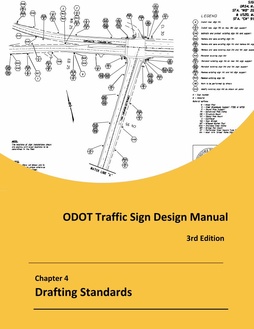
Chapter 4
Drafting Standards
ODOT Traffic Sign Design Manual
3rd Edition
3rd
Edition ODOT Traffic Sign Design Manual
Chapter 4 | Drafting Standards 46 Oregon Department of Transportation
July 2015 Traffic Standards Unit
4 | Drafting Standards
General
CADD Files
You will not be able to start putting together your signing plans without first obtaining the necessary
electronic data from the Roadway Designer. These CADD files that you will need include existing
features files, alignment files, new construction files, right-of-way files, etc. Once you have gathered all
of these, you should have what you need to begin your own design files. Compromise
Design Format
The vast majority of design work produced for ODOT contracts is done in 11” x 17” format using
surveyed alignments. On some preservation jobs of minor complexity an 8½” x 11” format may be
selected by the roadway designer. When this happens, the signing plans will need to be developed for
that same format. This manual focuses on the production of plans in 11” x 17” format.
In some cases, a surveyed alignment either does not exist for a particular project or may not be available
to the sign designer for producing their plans. When this is the case, the designer should create their own
“alignment” using straight-line format. The designer drafts straight segments of roadway, with an
assumed center-line, to serve as the alignment for the sign plans. The designer then adds center-line
stationing or mile point references consistent with those used by the roadway designer.
The designer should always contact the roadway designer or Project Leader before starting design work to
coordinate the proper format. It is difficult to change formats later on when the design is mostly finished.
Consolidation of Base File
The first step is to create a “base” file to set up your plan sheets. This file should be set up to include all
of the features necessary to show on your plan sheets and leave out the unnecessary ones. Begin by
merging all of the necessary files (existing features file, right-of-way file, alignments, new roadway file,
striping design file) together into a single two-dimensional file. This newly created base file will later be
used as a reference to your design file.
As you progress through your design, keep in mind that the Roadway Designer is also progressing
through their design. Along the way, there will often be changes made to alignments or other geometric
features. Because of this, it is advisable to update your base file, as needed, by referencing in the most
current files for alignments and new construction. An open line of communication with the Roadway
Designer will be your best tool for determining when to do this. They can let you know when they are
making changes that will significantly affect your base file. Anytime your plans are printed and
distributed for review they should show alignments and other features consistent with the Roadway plans.
This can only be accomplished by keeping an up-to-date base file.
ODOT Traffic Sign Design Manual 3rd
Edition
Oregon Department of Transportation 47 Chapter 4 | Drafting Standards
Traffic Standards Unit July 2015
For some projects, minor in scope and complexity, there either will be no Roadway plans or they may
only consist of typical sections. In this case, you will not have the usual information available to you
necessary to create a base file for your design. There are two other options available to you. The first
involves “borrowing” alignment from as-builts of previous projects at that location. The second involves
using the straight-line format described in the previous section on “Design Format”.
File Clean-Up
After creating the base file, the sign designer’s next goal is to clean out extraneous information. This is
accomplished through a combination of turning off levels and deleting unwanted elements. There is some
information that you won’t want in your plans but will still want to keep as a resource, such as utilities,
easements, curve data and existing signing data. Take care not to delete these items, because you will
need to refer back to them on occasion. The items that you will want to show on your plans include:
center-line,
stationing and station marks,
lane lines,
edge of pavement,
curbs,
sidewalks,
barriers,
bridges,
street names,
north arrows, etc.
Also include lane-use control arrows at intersections to show allowed turning movements. It will prove
useful to incorporate actual striping features into your plans; if possible, since the lane lines and markings
in the roadway design files won’t always match those shown in the actual striping plans.
Items such as landscape features, buildings, and drainage features will clutter up your plans and should
not be shown for this reason. In some cases, a lane line may conflict with the center line. In this case, the
lane line should be deleted so that the center line stands out more clearly.
Once extraneous information is removed, some line codes and weights may need changing for
consistency with ODOT drafting standards. For instance, the center-line in the roadway file is usually a
heavy solid line. ODOT drafting standards require a line weight of zero with a line style of seven. The
stationing tick marks also have a line weight of zero, but would remain a solid line style. One other
possible change involves the line style used for new curbs and barriers. Often these are shown with a
dashed line style in the roadway files, but ODOT standards call for them to be solid.
Do not show existing striping and other pavement markings on your plan sheets unless they are being
maintained as is. Do not show both the new and the existing edge of pavement lines on your plans when
they are in nearly the same location, as is the case in a project with only minor widening. In this case
reduce the clutter by not showing the old edge of pavement. In cases where the new and the old edge of
pavement differ considerably, as in projects with significant realignment, show both. This can be helpful
in eliminating confusion as to why existing signs sometimes are shown in the middle of the new
alignment or far beyond the new edge of pavement.
You will also need to replace all of the symbols for existing signs with the sign symbols that are included
in the ODOT pull-down menu. This is necessary because the sign symbols from the original existing
features file used to create your base file are very small and hard to see. The symbols in the pull-down
menu are built to a scale such that they will stand out much better on your plan sheets and it will be much
easier to show orientation of sign faces with these symbols.

3rd
Edition ODOT Traffic Sign Design Manual
Chapter 4 | Drafting Standards 48 Oregon Department of Transportation
July 2015 Traffic Standards Unit
Creating and Naming a Design File
Once you are comfortable with the way your base file looks, it is time to start building your design file.
Your design will be put together in a separate file with your base file referenced to it as needed to develop
your plan sheets. Begin by opening a new two-dimensional design file in Microstation. The naming
convention for signing files uses the five digit key number followed by the letters “tr” for traffic and the
suffix “.sn1”. As an example, for a project with the key number 05925, the sign design file would be
named 05925tr.sn1. If you have need for more than a single design file, then the suffix would increase
with each additional file (.sn2, .sn3, etc.).
This file will contain all of the design notes and bubbles, borders, title block, and any of the text needed
for the contract plan sheets.
Sheet Borders
Once you have created and named your design file, open it up. Set up all of your plan sheets in this file
and reference pieces of your base file to individual plan sheets to cover the entire length of the project.
Consultants may have a different method to set up sheet borders and plot sheets than ODOT uses.
Although the approach may be different, the goal is still the same. You want your file set up in a manner
that has organized rows or columns of identical sheet borders placed and identified in such a manner as to
allow for quick and easy prints. ODOT uses a tool called Print Organizer, within the Microstation V8i
environment, that allows for customization of how your sheets are organized and printed, both on paper
and digital. By creating “print set” definitions, a collection of any or all sheets in a design file can be
identified for printing (paper or digital) in a selected order, without requiring individual fencing of sheets.
For this manual, we will focus on setting up a design file by using Print Organizer.
Begin by placing sheet borders for 11” x 17” sheets at a 1200 scale (1” = 100’) in your file. The number
of borders you place doesn’t matter so much at this point, because you can add more or delete some later,
as needed. You will eventually need enough borders to take care of all Signing Plan sheets, Sign Detail
sheets, and Sign and Post Data Tables.
There are a number of features common to all sheets in your design file. Once you have created your
sheet borders, place these common features inside of your first sheet border. Copy these features to all
sheet borders, so that you don’t have to create them anew for each sheet. Among the features common to
all or most sheets are: title block (with professional stamp), sheet header, LEGEND notes and general
notes (plan sheets only), and PRELIMINARY (or ADVANCE) COPY “stamp”. These items can be
found among the “General” or “Signing” workflows that are a part of the overall “Traffic” workflow. For
consultants, we have available on the ODOT web-site sample sheet borders and title blocks. They are
available at the following web site:
http://www.oregon.gov/ODOT/HWY/TS/Pages/signing.aspx#Microstation_Plan_Sheets.
ODOT Traffic Sign Design Manual 3rd
Edition
Oregon Department of Transportation 49 Chapter 4 | Drafting Standards
Traffic Standards Unit July 2015
Whatever LEGEND or general notes are used can usually fit in the area directly above the title block and
below the sheet header. After placing this information inside of the first sheet border it can be fenced and
copied inside of all other sheet borders. The title block will be the same on all sheets. Sheet headers and
general notes will be used on all plan sheets and details sheets although the contents will differ somewhat
for each of the two types. Sign and Post Data Table sheets all have the same spreadsheet type of layout to
them. This also is a standard cell which can be accessed from within the “Signing” workflow. The cell
can be placed inside of each sheet border that will serve as a data table. ODOT has also provided blank
data table sheets for consultant use within the same file mentioned above.
Plan Sheets
After customizing your sheet borders and copying from sheet to sheet all of the common information, you
are now ready to begin laying out your plan sheets. There’s more than one way to accomplish this task,
but this manual will focus on one specific method, which involves referencing portions of the base file
into individual plan sheet borders in the design file.
All of the existing traffic signs should be included on the signing plan sheets. This includes signs to be
maintained and protected, signs to be removed, and signs to be replaced. When all of the signs are
included on the plan sheets, the plans can be reviewed with a clear picture of all the signs located within
the project limits. This will also be beneficial when the plans are filed as “as-built” records for that
section of highway.
Sample Traffic Signing Plans and Plan Sheets are available on the TRS web site located at:
http://www.oregon.gov/ODOT/HWY/TS/Pages/signing.aspx#Microstation_Plan_Sheets.
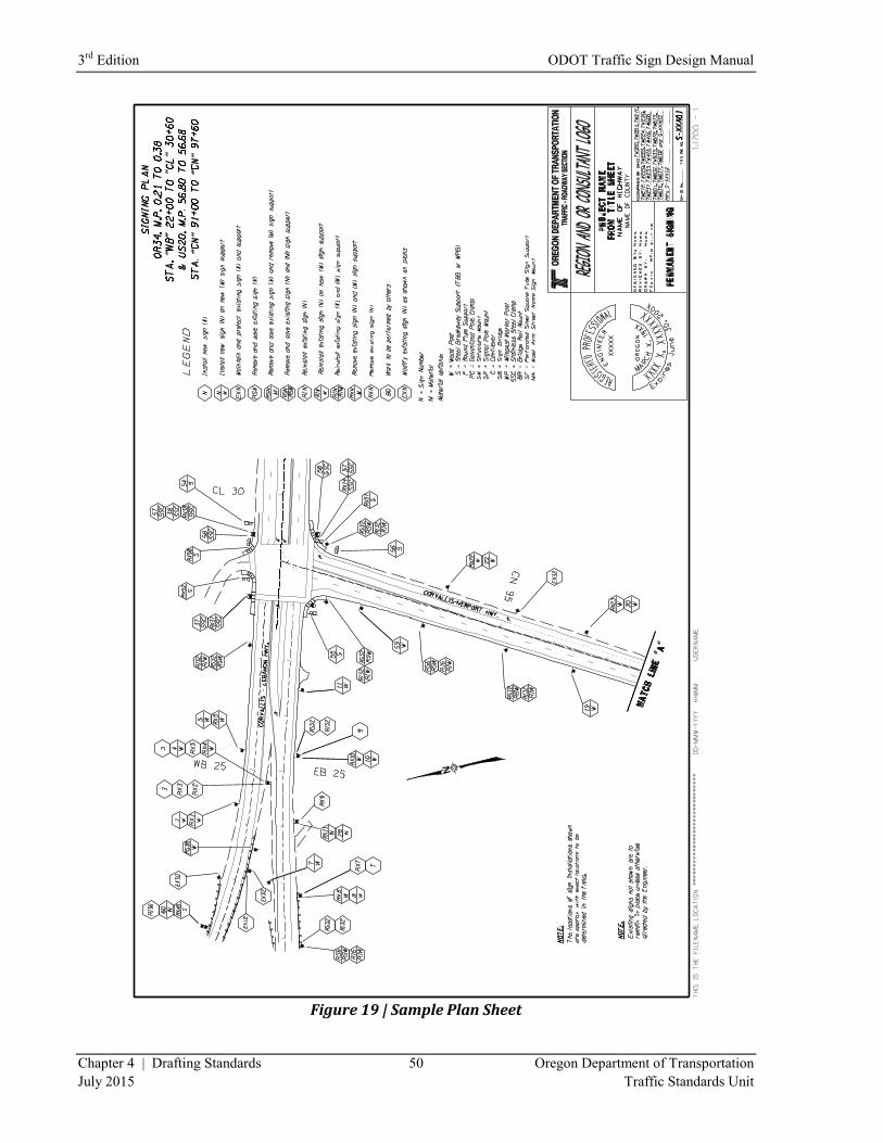
3rd
Edition ODOT Traffic Sign Design Manual
Chapter 4 | Drafting Standards 50 Oregon Department of Transportation
July 2015 Traffic Standards Unit
Figure 19 | Sample Plan Sheet
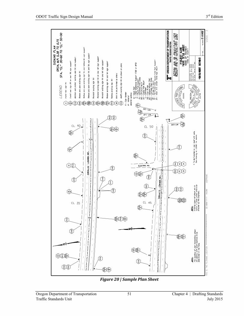
ODOT Traffic Sign Design Manual 3rd
Edition
Oregon Department of Transportation 51 Chapter 4 | Drafting Standards
Traffic Standards Unit July 2015
Figure 20 | Sample Plan Sheet
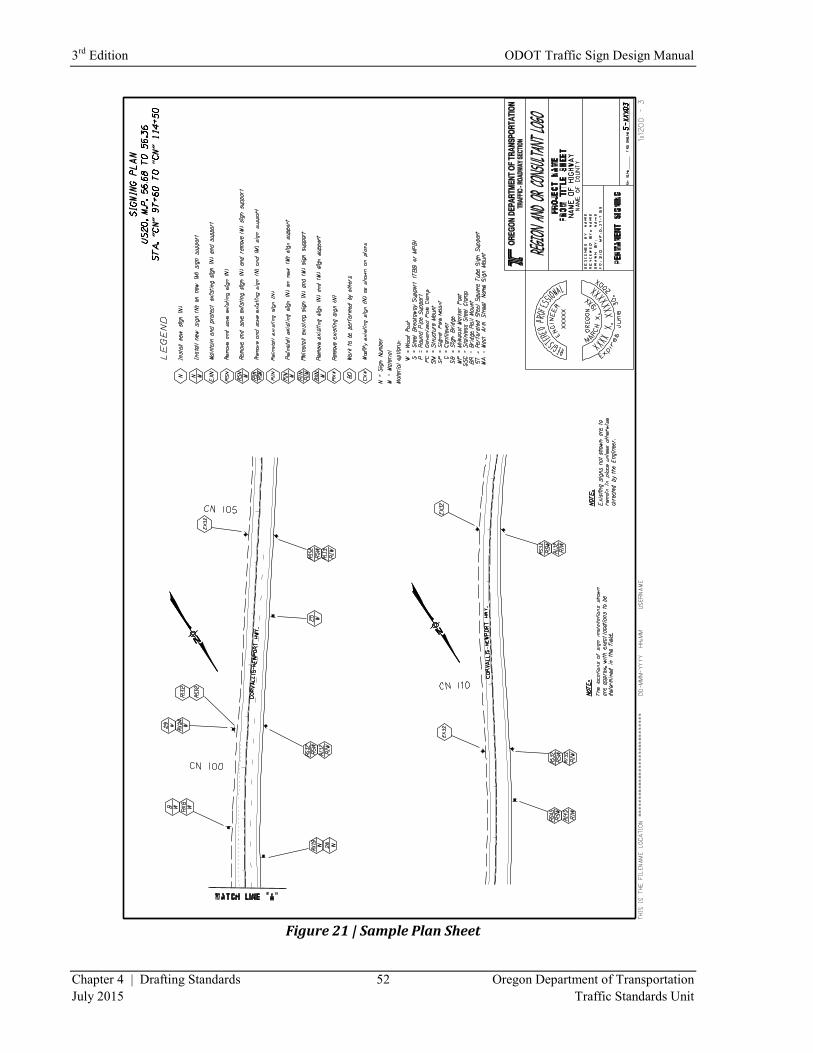
3rd
Edition ODOT Traffic Sign Design Manual
Chapter 4 | Drafting Standards 52 Oregon Department of Transportation
July 2015 Traffic Standards Unit
Figure 21 | Sample Plan Sheet
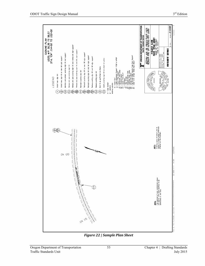
ODOT Traffic Sign Design Manual 3rd
Edition
Oregon Department of Transportation 53 Chapter 4 | Drafting Standards
Traffic Standards Unit July 2015
Figure 22 | Sample Plan Sheet
3rd
Edition ODOT Traffic Sign Design Manual
Chapter 4 | Drafting Standards 54 Oregon Department of Transportation
July 2015 Traffic Standards Unit
Clip Boundary and Referencing of Files
On most 11” x 17” plan sheets your usable design space will be an area of about 10” x 10”. Within this
space you should be able to comfortably fit two different stretches of highway alignment of lengths
anywhere from 800 to 1000 feet. Begin by creating a box (rectangle) of approximately 4” tall by 9” (400’
x 900’) wide. Create it on a level which does not need to be turned on for your final prints. The boxes
can be made with construction lines and turned off for printing. Place this box over adjoining pieces of
alignment in your base file, from beginning to end of the project, such that the entire alignment is covered
with minimal overlap. Each box should be rotated, if necessary, such that its length runs more or less
parallel with the center line of the alignment.
If you have an interchange or a cross road which has a considerable amount of work on it, you may need
to limit that particular sheet to only one section of alignment, instead of the two. If this is the case, you
may want to use a 9” x 9” (900’ x 900’) box to mark that particular section of alignment. Once you have
these boxes placed end-to-end covering the entire alignment, you may want to reposition them as needed
to insure that all important features, including station numbers are encompassed within them. Also make
sure that within each box there is a North arrow to define orientation of the alignment. Make sure that
text for highway names and any crossroads are present within each box.
Once you’ve arrived at this point, the idea is to individually fence around each box and copy their
contents as references to the sheet borders within the design file. The fence contents may need rotating
on the page as they are referenced to make the boxes run horizontal. Some sheets will have room for two
boxes, one above the other. Other sheets will only have room for a single box if it is the 9” x 9” (900’ x
900’) variety. The sheets need to be filled systematically, so that the overall alignment stationing
increases left to right and top to bottom from first sheet to last as if reading a book.
To begin the referencing, put a fence tight around the outside of the first box at the beginning of the
project alignment. Now attach this as a reference to your design file inside of the sheet border for the first
plan sheet. One way is to name the reference according to the sheet number and whether it takes up the
top or bottom portion of the sheet. Remember, most sheets will have two separate portions referenced to
them, one on the top and the other on the bottom. Make sure that you have specified “clip boundary” and
that your fence setting is on “clip” when you “move” the referenced material into its position within the
design sheet border. Rotate this referenced material, as needed, so that the alignment is horizontal on
your plan sheet and make note of the degree of rotation used.
Repeat this procedure for each of the remaining boxes in order of increasing stationing until you have
filled in each of the plan sheets with the necessary alignments. If referenced properly, the boxes
themselves will also show up on the plan sheets. The unique level which these boxes should have been
created on can be turned off before making any prints so that they will not show up on your actual printed
plan sheets.
ODOT Traffic Sign Design Manual 3rd
Edition
Oregon Department of Transportation 55 Chapter 4 | Drafting Standards
Traffic Standards Unit July 2015
As mentioned earlier, for some projects an actual surveyed alignment is not available to the sign designer,
and a straight-line format is necessary. In this case, instead of referencing pieces of alignment from a
base file into the design file, the designer creates horizontal pieces of alignment directly onto each plan
sheet and drafts a center-line using milepoints or stationing to match that which is shown on the sign
inventory they were provided. No particular scale is necessary, but it should use as few sheets as possible
without making the sign symbols so crowded together that the information is difficult to read. If there are
long sections of highway with no signs present, the designer may consider leaving these sections out.
Mapping Existing Signs
After referencing the base sheet alignment to the plan sheets, begin plotting the existing sign locations
onto each sheet. Most or all of the existing sign locations should appear on your alignment from the
original existing features file. The original sign symbols should all be replaced with the symbols from the
pull-down menu. Next, compare the locations listed in the sign inventory with the locations shown on the
plan sheets. You may find that some of the locations in the inventory are missing from the plan sheets or
vice-versa. You may also find that some of the symbols are not shown in the exact location as listed in
the inventory or that some of the symbols are not oriented with the signs facing the same direction shown
in the inventory. If you run into conflicts such as these, it is best to resolve them by looking at the digital
video log or by making a trip on-site for projects. Add or move any sign symbols as needed according to
what you are able to determine is the most accurate representation of what signing is currently in
particular locations.
At this point, you might make paper prints of all the plan sheets and begin making note (in ink) of what
each existing installation consists of. Another alternative is to place the cell symbols for the signs within
your plan sheets on a construction level. Draw a line from each sign face to a blank area on the page
where you can sketch a rough version of what that particular sign(s) looks like or use a brief word
message like “speed 35”-whichever is easiest for you. Do this for all the signs in the project. You will
want to differentiate existing signing from proposed new signing. When you later begin marking in
locations for proposed new signing, you will want to use pencil, because you may make numerous
changes before settling on a particular plan. This is the reason for using ink to designate the existing
signing.
You should not need to make any written indications about the types of supports. There are different
symbols available in the ODOT pull-down menu, and from other sources, for each of the different types
of commonly used supports: wood posts, steel posts, pipe installations, signal pole mounts, cantilevers,
etc. Use the representative symbol for the appropriate type of support used. Also, use symbols which
accurately depict the number of posts present in the installation, as well as showing sign faces on all sides
of the support where present. Whether it is an existing installation which might be removed and
discarded or new signing and supports to be installed, it is important to provide an accurate picture of
what is currently out there and what is desired, to eliminate any confusion later on when the plans are read
by a contractor or inspector.
3rd
Edition ODOT Traffic Sign Design Manual
Chapter 4 | Drafting Standards 56 Oregon Department of Transportation
July 2015 Traffic Standards Unit
Use of Legend Notes
Once you’ve completed a rough layout of all signing, existing and proposed, on your plan sheets, indicate
the action to be taken for each installation shown. In the ODOT pull-down menu is a complete set of all
commonly used LEGEND (bubble) notes. These notes are in the form of hexagons, with enclosed letters
and numbers, used to indicate action(s) to be taken with regards to each sign and/or support. Within each
bubble, the number (N) represents the sign number in question. The letter (M) in the bottom half of the
bubble represents the type of support: wood, steel, cantilever, pole-clamp, etc. The other letters in the
bubble (RX, EX RS, RI, etc.) represent the action(s) to be taken to the sign and/or support. Each plan
sheet should include a list of the LEGEND notes used on that particular sheet. At the bottom of the list
are definitions for each coded message and for the various possible support types. The most common
possibilities are included in the ODOT pull-down menu.
Sign installations may have signs facing only in one direction or facing in two or more different
directions. In using bubble notes, use a separate string of notes for each sign face. Begin by drafting a
leader line outward from one of the sign faces. At the end of this leader line, place the string of bubble
notes needed to sufficiently describe the work to be performed for each sign on that face. The bubbles
should be in order, moving outward, so that they are representative of how the work would actually be
accomplished. Begin with bubbles that show existing signs being removed followed by bubbles that
show new signs being installed. Repeat this process for each sign face in the entire installation. Although
an installation may have signs facing in multiple directions, there is only one common support for that
installation. Once the removal and/or replacement of the support has been detailed with one of the bubble
strings, there is no need to repeat it on any of the other strings for that installation.
Sign Details
In order to adequately explain the signing work to be accomplished on a project, you need to provide the
contractor with a detailed description of the signs, both existing and new. This task is partially
accomplished by developing Sign Detail sheets that include the likeness of each sign. Not only is this
necessary for performing the work under contract, but these sheets will prove beneficial later on as a set
of as-built records for that area.
Format of Detail Sheets
There is an example of a Sign Detail sheet at the end of this Section that you can refer to for the layout of
this sheet. Start the sign drawing at the upper left corner and then proceed down the sheet in rows until
the sheet is full. The signs within any particular row are left-justified with respect to each other, and the
sign numbers are centered below each respective sign. Allow an adequate amount of space between signs
within each column and between each of the columns so that the sheets do not appear cluttered and are
easy to read. Sign numbering is obtained by going back to your penciled-in plan sheet.
One way to number your project is to start with the first sign at the beginning of the alignment on your
first plan sheet and call it number one. The corresponding design should be placed in the upper left
corner of the Sign Detail sheet and labeled Sign No. 1. Working ahead on line, the next sign would be
numbered 2 and so forth. All the signs on the Sign Detail sheet are numbered in this fashion.
ODOT Traffic Sign Design Manual 3rd
Edition
Oregon Department of Transportation 57 Chapter 4 | Drafting Standards
Traffic Standards Unit July 2015
This is the easiest way to number your project, but it doesn’t always produce the best-looking Sign Detail
sheets. You will end up with some small signs mixed in with some very large signs, and will not make
very efficient use of the space on your sheets.
Another way to number your sheets and make better, more efficient use of the space on your Sign Detail
sheets is to begin at the start of the alignment and proceed ahead on line numbering the smaller
regulatory, warning and other standard signs first. Once these signs have been covered for the entire
project, repeat the process for the smaller guide signs and other small signs requiring custom designs.
Last of all, repeat the process for the larger guide signs and other large signs requiring custom designs.
By using this second method, the signs on your Sign Detail sheets line up more uniformly and use the
space more efficiently. This method places signs requiring custom designs at the end of the Sign Detail
sheets.
Signs that supplement each other should share the same sign number. Examples include a warning sign
with an accompanying speed or distance rider, a guide sign with secondary route assemblies or
recreational symbols mounted below it, or a guide sign with an exit number sign mounted above it. In
each of these cases, the entire collection of signs would be shown together in one location on the Sign
Detail sheet and given a single sign number. To differentiate between the primary sign and the
supplemental signs, each of the supplemental signs would be further designated by a specific suffix. So,
if the entire collection was known as sign number 1, then the supplemental signs accompanying the
primary sign would be labeled as 1a, 1b, 1c, etc. In this manner, the entire collection of signs that
supplement each other on that particular sign face can be referred to as sign number 1 in the bubble notes
on the plan sheet. At the same time, each individual sign in that collection has its own unique designation
that can be referred to later on in the Sign and Post Data Tables, when more specific details are required.
Once a particular sign has been located and numbered on the Sign Detail sheets do not show it again. For
example, if sign number 1 is a STOP sign, then refer to every other STOP sign on the project as sign
number 1. Any signs that will be removed altogether, or otherwise not replaced with new signs, will be
drafted with dashed (broken) borders on the Sign Detail sheets. Draft others that will require new signs
with solid borders.
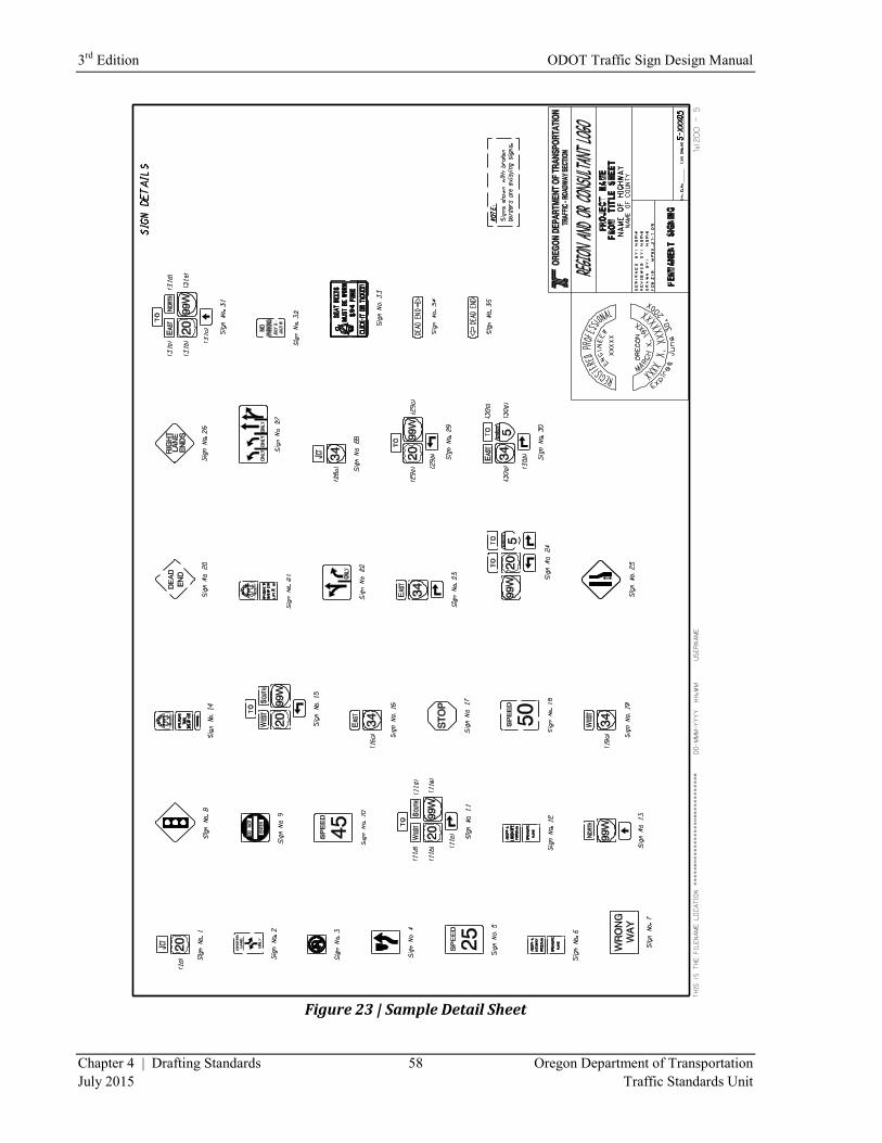
3rd
Edition ODOT Traffic Sign Design Manual
Chapter 4 | Drafting Standards 58 Oregon Department of Transportation
July 2015 Traffic Standards Unit
Figure 23 | Sample Detail Sheet
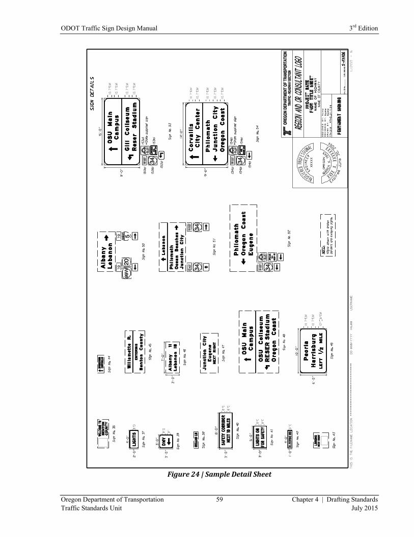
ODOT Traffic Sign Design Manual 3rd
Edition
Oregon Department of Transportation 59 Chapter 4 | Drafting Standards
Traffic Standards Unit July 2015
Figure 24 | Sample Detail Sheet
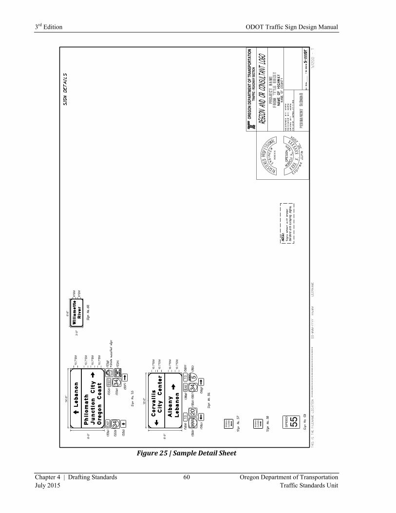
3rd
Edition ODOT Traffic Sign Design Manual
Chapter 4 | Drafting Standards 60 Oregon Department of Transportation
July 2015 Traffic Standards Unit
Figure 25 | Sample Detail Sheet
ODOT Traffic Sign Design Manual 3rd
Edition
Oregon Department of Transportation 61 Chapter 4 | Drafting Standards
Traffic Standards Unit July 2015
Regulatory and Warning Signs
When building your Sign Details sheets, you will find that most of the more common regulatory and
warning signs are already depicted in cell libraries or cache files, for your convenience. The Guidsign
Sign Design program, used for designing custom signs, also contains a library of cells for the most
common regulatory and warning signs shown in the MUTCD. It also includes many styles of route
shields and a number of standard recreational and motorist services symbols. Any of these cells which
apply to your particular project can be copied to your Sign Detail sheets. You’ll want to take advantage
of this and other cell libraries that you have access to so that you don’t have to spend a lot of time drafting
these standard signs over and over again. A good source for these standard signs is a cache file on the
ODOT web-site (See “Plan Sheets” section of this chapter for website). The file is referred to as
“Standard Sign Details in Microstation”. This cache file contains a number of signs which do not appear
in the MUTCD because they are unique to Oregon.
Regardless of what source you obtain your sign depictions from, it is important that they closely resemble
the actual signs needed on your project, so that there is no question on the part of the contractor as to what
signs they need to install. These depictions should be drafted at a scale large enough to be easily
recognized, but small enough that you can get a reasonable number of them on a sheet. With these
smaller standard signs, you could show 25 to 40 signs on a single sheet. They should also be scaled with
respect to each other such that signs which are the same size actually appear the same size on the sheet. If
one sign is twice the size of another, draft it such that it is twice the size on the sheet. If you cannot find
an exact depiction of a particular standard sign, then you can usually find a sign which is very similar and
modify its legend to make the sign that you need. Once you have done this, you may want to consider
creating your own cell of this sign for future use.
Guide Signs
Most guide signs are unique to a particular location. There are standard layouts for signs such as exit gore
signs and exit number signs, but even though the overall dimensions for these signs are set, the spacing of
the legend will vary with the exit number. Because of this, a unique design layout should be worked up
for each guide sign. Using your sign design software, produce likenesses of each guide sign for
placement onto your Sign Detail sheets. Use the sign design software in a design file other than your
project design file. That way, if the software malfunctions for some reason, it won’t destroy any of the
information being developed on your plan sheets. As each sign is designed it can be copied into the
project design file using the clipboard feature. Copy the necessary dimensioning text along with each
sign. Ideally, each guide sign should include dimensioning text showing the overall height to the left of
the sign, overall width above the sign, and letter sizes and fonts as well as arrow and shield sizes to the
right of the sign. Do not show any dimensions below the signs, if possible. Begin with the smaller guide
signs such as street name signs and work your way up to the larger signs as you build your sheets. The
signs will fit more uniformly on the sheets and you’ll use the space more efficiently by doing this. Refer
back to Chapter 2 “Designing Guide Signs” for information on the actual design of the sign.
As you copy the signs onto your Sign Detail sheets, be sure to scale them appropriately so that they are
proportionately sized with respect to the regulatory and warning signs that you have already placed on the
Sign Detail sheets. Place the text for the sign dimensions such that its size is consistent from sign to sign.
Use a text size that is easy to read, but otherwise does not take up a lot of room or interfere with the actual
depiction of the sign.

3rd
Edition ODOT Traffic Sign Design Manual
Chapter 4 | Drafting Standards 62 Oregon Department of Transportation
July 2015 Traffic Standards Unit
Show all signs on a particular face that are installed together as a single sign number. Use suffixes for
each sign other than the primary sign within each sign number. As an example, if you have a primary
guide sign that contains two route shields, has an exit number sign mounted above it, and has an “exit
only” panel at the bottom of it, you would refer to the entire collection as sign number 1. The exit
number sign might be referred to as 1a, the “exit only” panel as 1b, and the route shields as 1c and 1d. By
doing this you can refer to the entire installation as sign number 1 on the plan sheet(s), but still be able to
identify each sign separately when more detail is required in the Sign and Post Data Tables, which we
will discuss later in this chapter.
In most cases a guide sign will be one of three colors: green, blue or brown. The color depends on the
type of destination(s) that you are directing people to. There will be some cases where a guide sign will
need to be partly green and partly brown or blue. In other cases, a guide sign will include a yellow “EXIT
ONLY” message at the bottom. For either of these scenarios, it is best to label with the suffixes “a” and
“b” to differentiate between the two colors on the same sign. Later, in the Sign and Post Data Table you
will need to give more specific details as to the type of sheeting and the dimensions involved for each
color, so the use of these suffixes will allow you to detail each of the two colored portions separately.
Sign Design Software
There are several programs available to design and draft the signs not available in the signing cell library.
ODOT uses “Guidsign” sold by Transoft Solutions, 604-244-8387, Fax 604-244-1770. “Signcad” is
another very similar system that will design and draft the sign for you. It is sold by Sign Cad Systems,
Inc., 952-544-9559, Fax 952-544-9561, or on the web at www.signcad.com. The advantage of using
software to design the signs is the speed of the design plus the drafting is to scale so what you see on the
design is an exact replica of what the finished sign will look like.
If using software to design signs for a project, you will need to print the design for each sign out
individually for the shop drawings required with your sign plan. The sign designer will be asked to send
these drawings to the Construction Project Manager’s office and they will provide them to the Contractor
for the Project. The Sign Manufacturer uses the drawings to build the signs according to their design.
Make sure that the sign numbers on the drawings match those shown on the Sign Details sheets. Also,
make sure that the information on the drawings regarding sizes, sheeting types and colors, etc. matches
the information entered into the Sign and Post Data Tables (see next section).
Sign and Post Data Tables
There is a completed form of a Sign and Post Data Table at the end of this section that you can refer for
the layout of this sheet. We will go through this form column by column, explaining what type of data
needs to be entered in each case. Some examples will be provided along the way, and the completed data
table at the end of the chapter should also be examined while reading through the instructions for each
column. You should read through this entire Chapter prior to filling out a Sign and Post Data Table for
the first time.
ODOT Traffic Sign Design Manual 3rd
Edition
Oregon Department of Transportation 63 Chapter 4 | Drafting Standards
Traffic Standards Unit July 2015
Before beginning to fill in the data tables, tally up the number of each individual sign needed to complete
the work shown in the plans. Count entries only where a new sign and/or support are to be installed or
where an existing sign and/or support are to be removed, saved and reinstalled or somehow modified. Do
not count signs and supports removed and not replaced or signs and supports maintained and protected in
their existing location. Once you have your tally completed, you can begin filling in the first data table.
You may want to leave a few empty lines after each sign number if you anticipate the need for additional
signs in the future.
Sign Number & Sign Location
Start with sign no. 1 and make your entries in numerical order. If you have three installations tallied for
sign no. 1, then you will fill in data in three different rows. In this case you would only need to enter the
number “1” for the first row. It would be understood that the other following rows were also number 1
unless otherwise numbered. If your sign no. 1 has a secondary sign (1a) along with it, then you will be
filling in data in six different rows. The entries in the sign number column would read “1, 1a, 1, 1a, 1,
1a” as you work your way down. Entries are only needed in the sign location column for the rows next to
number 1 (not 1a), because the location of 1 and 1a would be the same in each case. For the sign location
column, it is preferred that the entry consist of an alignment name, engineering station and a designation
of “lt.” for left of center-line or “rt.” for right of center-line, when looking ahead on line. If the
installation is in the median, then use the designation “ctr.” If engineering stationing is not available, as is
the case in some preservation overlay projects, then enter mile points, to the nearest one-hundredth of a
mile, into the sign location column. A directional suffix (EB, WB, NB, SB) should accompany them to
indicate which side of the highway the installation is on.
After completing each of the rows for sign no. 1, skip a row and begin making entries for signs numbered
2, then 3 and so on until all numbers have been covered. It is best to leave a blank row after finishing the
entries for a particular number. This provides a little separation and makes the data tables easier to read.
Sign Dimensions
These entries are simply the width and height for each sign. For guide signs and other larger custom
designed signs enter these values in terms of feet and inches as determined by the custom sign design
software used in their design. For the smaller custom signs and all standard signs (regulatory signs,
warning signs, shields, arrow boards, rec. symbols, milepost markers, etc.) show the dimensions in inches
only. Dimensions for most of the more common regulatory and warning signs are included in Appendix
D. Dimensions for other standard signs can be found in FHWA’s Standard Highway Signs, our Sign
Policy and Guidelines, and our Standard Drawings (TM200 series). If you are detailing a sign which
already exists in the field, then bracket each dimension with parenthesis to differentiate it from the new
signs. It is not always necessary to show dimensions for existing signs, but it will prove useful if that
existing sign needs a new support. Sign sizes are needed for the contractor or project inspector to be able
to field verify sizes of new supports.
3rd
Edition ODOT Traffic Sign Design Manual
Chapter 4 | Drafting Standards 64 Oregon Department of Transportation
July 2015 Traffic Standards Unit
Border Width & Radius
These columns will be discussed together as they are closely related. Check the columns for guide signs
only. Simply place a check mark in whichever column applies for the border width of the particular sign.
Guidance for determining the appropriate border width is provided in Section 00940.45(c) of the 2008
Oregon Standard Specifications for Construction. Determination of the corner radius is explained in this
same section. ODOT has five standard values allowed for radii of custom designed guide signs (1½”, 3”,
6”, 9” and 12”). To calculate a radii, take the smaller of the two dimensions shown (in inches) in the
width and height columns and divide this value by eight. The resulting value is then rounded up or down
to the nearest of the five values allowed. If the resulting value fell exactly in the middle of two of these
five values, then it would be acceptable to round up or down either one. Place a check mark in the
column that you have determined as the appropriate radius.
Some guide signs, such as exit gore signs and exit number panels require custom designs simply because
each exit number is unique and the legend spacing will vary a little from number to number. Otherwise,
these signs have preset standards for overall dimensions, legend size, etc. There are also preset values for
the border widths and corner radii on these signs. Use these preset values instead of the guidelines
previously mentioned.
Arrow Information
This column applies only to guide signs. If there are no arrows on the sign, then leave this column blank.
If there are multiple arrows of varying size, then enter “various” in the column. If there is only a single
arrow or multiple arrows all of the same size and type, then enter this size and type in the column. The
entry should read “type – size”. An example would be “D – 8x12” for a Type D arrow measuring 8” x
12”. Other examples are “A – 22x36” for a Type A arrow measuring 22” x 36”, and “DN – 32x22” for a
32” x 22” Down Arrow.
The arrow size is measured in inches and is shown as a” x b”, with “a” representing the width across the
arrow head and “b” representing the overall length of the arrow from the end of the shaft to the tip of the
head. Some signs, such as exit gore signs, have a standard size of arrow specified for them. On most
other guide signs, the appropriate arrow size must be determined by the designer. There are some very
general guidelines offered in the MUTCD for accomplishing this task. ODOT has also set up some
general guidelines to help in this matter. See Chapter 2 “Arrow Sizes and Design” for more details.
The types of arrows available are discussed in Chapter 2 of this manual.
Sign Type
Current sign types and their written descriptions are at the following web-site location:
http://www.oregon.gov/ODOT/HWY/SPECS/Pages/2008_special_provisions.aspx.
Once you have entered this site, select the “Part 02000” link. Then, upon entering that site, select section
02910 and scroll down to 02910.02 “Types of Signs”. Enter the applicable sign type (“B”, “C”, “G”,
“W1”, etc.) into this column for the specific sign detailed in that row. There are a large number of sign
types defined in the 02910 Special Provision, and it is important to have a clear understanding of the
specific ODOT sign types, to make sure that the information provided in the data table is appropriate for
the installation.

ODOT Traffic Sign Design Manual 3rd
Edition
Oregon Department of Transportation 65 Chapter 4 | Drafting Standards
Traffic Standards Unit July 2015
For an existing sign being reinstalled, simply enter “EXIST.” in this column. For a sign to be state
supplied, then enter an asterisk (*) in this column, and make an explanation in the “Remarks” column (to
be discussed later) that this is a state supplied sign.
Substrate
ODOT accepts only three types of substrate material for permanent signing on the state highway system:
sheet aluminum, plywood and extruded aluminum panels. Place a checkmark in the appropriate column
for each row to designate the desired substrate material for each specific sign. As a general rule-of-
thumb, ODOT only uses extruded aluminum panels for signs that are too large to be made of plywood.
This would be anything larger than what can be fabricated out of a 4’ x 8’ sheet of plywood. Some signs
that would otherwise be small enough to go on plywood should instead use extruded aluminum panels if
they have structural steel supports. These supports are designed for signs mounted to them with post clips
instead of being thru-bolted.
Extruded aluminum panel signs are designed in 6-inch increments for overall height and width, whereas
plywood and sheet aluminum signs are designed in 3-inch increments. Plywood can be used as a
substrate for signs up to 4’ x 8’ in size. Sheet aluminum can be used for ground-mounted signs up to 4’ x
5’ in size, and is also used as an overlay material riveted to extruded aluminum panels (route shields and
EXIT ONLY panels on large guide signs).
Because of its relatively light weight, sheet aluminum is also used for virtually all street name and lane
use control signs mounted on signal pole mast arms. Plywood is sturdy and therefore is resistant to
bending or warping around the support in high wind conditions or in snow-blowing operations. Because
of this, plywood may make for a better substrate material than sheet aluminum for signs wider than 3 feet
which would be the most susceptible to bending or warping in severe conditions.
Background Color
Abbreviations for each of the colors are listed in footnote number 1 at the bottom of each Sign and Post
Data Table. The written descriptions for each sign type, as shown in our Special Provision for Section
02910, will specify whether the background sheeting is ASTM Type III/Type IV or ASTM Type IX. The
color abbreviation is to be entered into whichever column is appropriate for that sign type.
Legend Color
There are three columns where information can be entered for the legend color. The legend color can
either be listed under the “ASTM Type III or Type IV” column, the “ASTM Type IX” column, or the
“Non-Reflective” column. You should choose only one of these columns for the sign legend and enter
the appropriate legend color.
Whenever your legend color is black, enter the abbreviation “BK” into the “Non-Reflective” column.
Black legend is always non-reflective. No other colors will be entered in the “Non-Reflective” column.
For all other legend colors, use the same abbreviations referred to previously in footnote number 1. Enter
the abbreviation for your sign color into whichever column is appropriate (“ASTM Type III or Type IV”
or “ASTM Type IX”). The written descriptions for each sign type from the specifications will help you
decide which column is appropriate.
3rd
Edition ODOT Traffic Sign Design Manual
Chapter 4 | Drafting Standards 66 Oregon Department of Transportation
July 2015 Traffic Standards Unit
Legend Type
Enter a checkmark into one of the two columns. If your sign is to be made of plywood or sheet
aluminum, then your legend type is direct applied and will always be considered “permanent”. If your
sign is to be made of extruded aluminum panels, then your legend is riveted on and will always be
considered “removable”.
Sign Number
This column is a repeat of the very first column. Copy the first column directly over to this column. It
makes the table easier to read if you have the sign numbers repeated in this location near the center of the
sheet. There is one additional feature that should be incorporated into this column, which does not appear
in the first column. This feature is individual designation for each separate post on a steel multi-post
breakaway installation. Provide extra rows to accommodate the total number of posts in your installation.
This allows you to enter design details for each steel breakaway post in its own specific row. This is
necessary because each post might have its own unique length and offset distance to specify.
As an example, for a steel multi-post installation (assume sign number 1) using three posts you would
allow for three rows to detail each individual post. In the first column the first row would have the
number “1” entered, but the next two rows would be left blank. The corresponding sign number column
in the middle of the sheet would have the following entries: 1L, 1C, and 1R, respectively in those same
three rows to represent the left, center and right posts. This will allow each of the three posts to be
detailed individually as you work your way to the right of the page across other columns. The
information specific to the sign would only need to be entered in the first row. There is no need to repeat
it in the other two rows. It is not necessary to detail posts separately for multiple wood post installations.
For those installations, the posts can all be detailed in a single row.
Type of Support
These 15-20 columns include all of the primary and secondary support types common to permanent
signing on ODOT’s highway system. Enter a check mark in the appropriate column or columns for each
sign. In most cases you will check no more than a single column for any given row. In a few cases you
may need to check more than a single column. For example, a triangular base breakaway support may or
may not have an “H” frame associated with it. If so, then you will need to insert a check in both of these
columns. Many installations will have a primary support and some secondary supports, as well. In such
cases, make sure that you enter your check marks for each column in the appropriate row corresponding
to the actual sign it supports.
As an example, a primary guide sign (number 1) may have two steel multi-post breakaway supports (1L,
1R), and it may have a secondary exit number sign above it (number 1a) supported by an exit number sign
support and another secondary sign (number 1b) mounted below it using a C4x5.4 channel support. In
this case, rows 1L and 1R (for sign number 1) would each have a check entered in the multi-post
breakaway column, the row for sign number 1a would have a check entered in the exit number sign
support column, and the row for sign number 1b would have a check entered in the C4x5.4 column under
secondary sign supports.

ODOT Traffic Sign Design Manual 3rd
Edition
Oregon Department of Transportation 67 Chapter 4 | Drafting Standards
Traffic Standards Unit July 2015
Some sign numbers and their corresponding rows will have no check marks entered in the support
columns. This is because each support, whether primary or secondary, is only to be detailed once in the
data table. This eliminates confusion when calculating actual material quantities needed.
For example, if a single wood post supports a STOP sign (number 1) and street name signs for two
different streets (numbers 2 and 3), then the wood post column would only be checked in the row for sign
number 1. The other signs (2 and 3) would not have any check marks in their rows for support types.
They would, however, contain notes in the REMARKS column (to be discussed later) indicating that their
support is detailed with sign number 1.
Detail each support only once, but make cross references so that it is obvious how each individual sign is
supported.
Post Size and Length
These columns are only filled in for the following types of supports: wood posts, perforated steel square
tube sign supports, triangular base breakaway sign supports, multi-post breakaway sign supports, exit
number sign supports and milepost marker posts. Lengths for secondary sign supports are also required
in the data table, but there is a separate column for this purpose next to the other columns which are
specific to secondary sign supports.
In the post size column, enter information specific to the cross-sectional size of the support. In the post
length column, enter the length of the support, usually in feet and inches. Further explanation is provided
in the following paragraphs. The actual design of supports and determination of appropriate sizes and
lengths is discussed in a later chapter on support design.
Post sizes for wood posts and perforated steel square tube sign supports have nominal cross-sectional size
in inches. ODOT uses wood post sizes of 4”x4”, 4”x6”, 6”x6” and 6”x8”. Perforated steel square tube
sign supports come in the following cross-sectional sizes: 2”, 2.25” and 2.5”.
Post lengths for wood posts are calculated in even two foot increments which is consistent with how they
are sold on the market (14’, 16’, 18’, etc.). The lengths shown represent the total length of post from the
bottom of the embedment (4’ to 7’ below the surface) to the top of the three inch reveal above the sign(s)
supported.
Calculate post lengths for perforated steel square tube sign supports to the nearest inch and show them in
terms of feet and inches. The lengths shown represent the total length of the main square tube post from
the bottom of the embedment (18” below the surface) to the top of the sign(s) supported.
Milepost marker posts all have a specific size detailed in Standard Drawing TM222. The designer can
either enter the specific size under this column or enter “SEE TM222” in this column to specify post size
for milepost marker posts.
Post lengths to be shown for milepost marker posts can be found on the previously mentioned chart on
Standard Drawing TM222. These values vary with the size of the milepost marker supported. Enter the
appropriate measurement (in feet and inches) from the chart.

3rd
Edition ODOT Traffic Sign Design Manual
Chapter 4 | Drafting Standards 68 Oregon Department of Transportation
July 2015 Traffic Standards Unit
Post sizes for triangular base breakaway and multi-post breakaway supports, as well as exit number sign
supports, have industry recognized structural member names. All exit number sign supports are short
flange members of a specific size (S 3x5.7). Use them in pairs and indicate the need for two of them in
your entry. All multi-post breakaway sign supports are wide flange members which come in a range of
sizes shown on Standard Drawing TM601 (W 6x9, W 6x12, W 6x15, etc.). All triangular base breakaway
sign supports are tubular steel members made of three-sixteenths inch thick steel. The available sizes are
shown on Standard Drawing TM602 (range from TS 3x3 thru TS 8x8).
Enter lengths for multi-post breakaway and triangular base breakaway sign supports in units of feet and
inches, in each case to the nearest inch. Unlike some of the other supports the length indicated does not
include the portion of the support below the surface in the concrete footing. Lengths shown for the multi-
post supports represent the entire post beginning at the top of the base plates and working up to the top of
the post at or just above the top of the primary sign. Lengths shown for the triangular base supports
represent the entire post beginning at the top of the base plates and working up to the top of the post. The
top of the post will not always coincide with the top of the sign(s). If a triangular base breakaway support
has an “H” frame, then the length is only calculated up to where the post ends at the “H” frame. This
coincides with a distance half way up the back of the sign. If the support does not have an “H” frame,
then the top of the post coincides with the top of the sign and the length shown should reflect that.
Exit number sign supports are used in pairs and will almost always be 7’ in length. This is the length
required for a standard application of this support which involves supporting a 30 inch tall exit number
sign above a primary guide sign, with the supports also running a length of nearly 4 feet 6 inches down
the back of the primary sign. These supports, however, are also used for signs other than exit number
signs, so the length needed could vary. It is also possible that the primary sign may be shorter than 4 feet
6 inches, requiring the exit number sign supports to be shortened so as not to extend below the primary
sign. Enter the appropriate length in feet and inches.
Footing Location and Minimum Depth
These columns are only for ground-mounted installations that specifically require concrete footings. That
limits it to multi-post breakaway sign supports, triangular base breakaway sign supports and perforated
steel square tube sign supports.
The location column should show an offset value, in feet and inches, representing the distance from a
particular point of reference to the center of the desired footing location. This point of reference is either
the edge of pavement, edge of travel lane (fog line), face of guardrail or concrete barrier, face of curb, or
back of sidewalk, whichever is most appropriate. Include a note in the remarks column to specify which
point of reference to measure from. This specified distance will allow the contractor to accurately stake
the location of the footing to insure that it gets installed where it needs to be.
The minimum depth column includes a measurement in feet and inches representing the total minimum
depth required for the concrete footing. For perforated steel square tube sign supports, the minimum
footing depth is always 3 feet. For multi-post and triangular base breakaway supports, the minimum
footing depths vary with the size of the support. These depth values can be found in the same charts
referred to earlier in Standard Drawings TM601 and TM602.

ODOT Traffic Sign Design Manual 3rd
Edition
Oregon Department of Transportation 69 Chapter 4 | Drafting Standards
Traffic Standards Unit July 2015
Referencing to Drawing Numbers
These columns list all of the Standard Drawings that you want to reference for any particular type of
installation. Check the columns that apply to the particular sign and/or support detailed within that row.
Check the TM600 and 601 columns for all multi-post breakaway (MPB) installations.
Check TM602 for all triangular base breakaway (TBB) installations.
Check TM635 for both MPB and TBB installations.
Check TM200 and 201 for all installations, because they contain information on vertical and
horizontal clearance requirements which pertain to all installations on ODOT highways.
Check TM675 for all signs made of extruded aluminum panels.
TM206 has information for installations using wind bracing.
Check TM677 and TM679 for all installations that use stainless steel clamps or special sign
brackets.
Check TM678 for all installations that use route marker frames or “C” channels for secondary
sign supports.
TM670 contains the sizing chart for wood posts and requires a check for all wood post
installations.
TM680 applies to signal pole mounts and should be checked for all such installations.
TM220 and 225 contain details which show how to properly install exit number signs and other
auxiliary signs relative to a primary guide sign.
Check this column for all MPB installations which have auxiliary signs mounted above or below,
and all other installations using exit number sign supports.
Check TM222 for all milepost marker post installations.
Check TM680, TM687 and TM688 for all installations using perforated steel square tube sign
supports.
Remarks
This last column is reserved for any remarks needed to further explain the installation of the particular
sign and/or support detailed within that row. Sometimes further explanation is needed in this column to
supplement the location or offset of a sign or footing. Installations that contain several signs, especially
when they do not all face the same direction, may need remarks added in this last column to explain the
orientation of a particular sign or to explain that the support for that sign has already been detailed for one
of the other signs. Sometimes a sign may need to be supplied by ODOT or another agency such as State
Parks. When this is the case, a remark should be added stating this. Use this column to refer to other
drawing numbers (plan sheets) that relate to some of your signs. Examples include referencing design
drawings for signal poles, cantilevers, sign bridges or other supports which relate to specific signs.
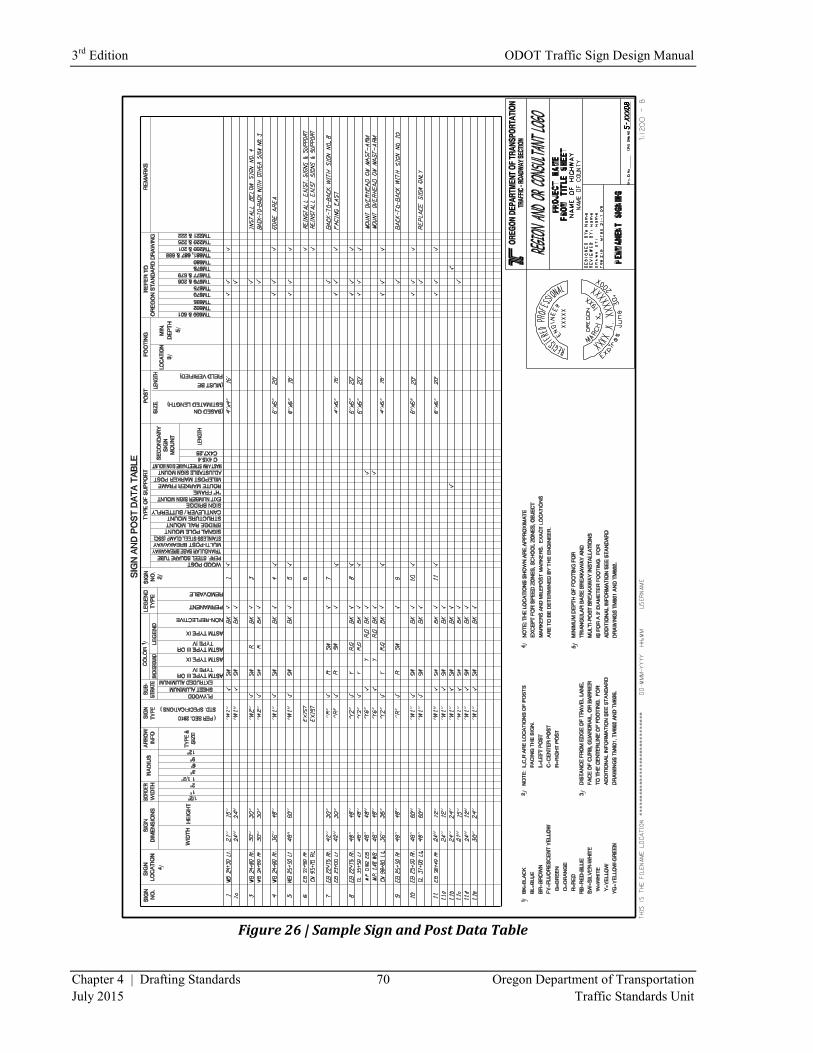
3rd
Edition ODOT Traffic Sign Design Manual
Chapter 4 | Drafting Standards 70 Oregon Department of Transportation
July 2015 Traffic Standards Unit
Figure 26 | Sample Sign and Post Data Table
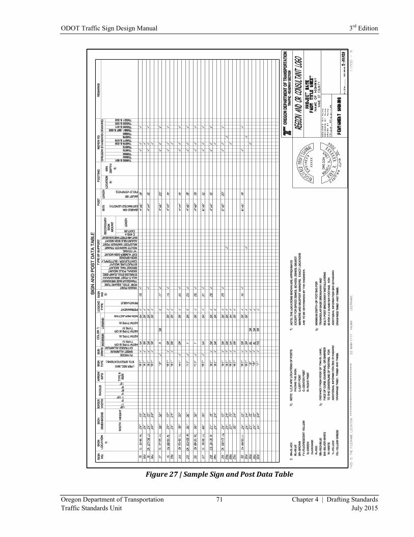
ODOT Traffic Sign Design Manual 3rd
Edition
Oregon Department of Transportation 71 Chapter 4 | Drafting Standards
Traffic Standards Unit July 2015
Figure 27 | Sample Sign and Post Data Table
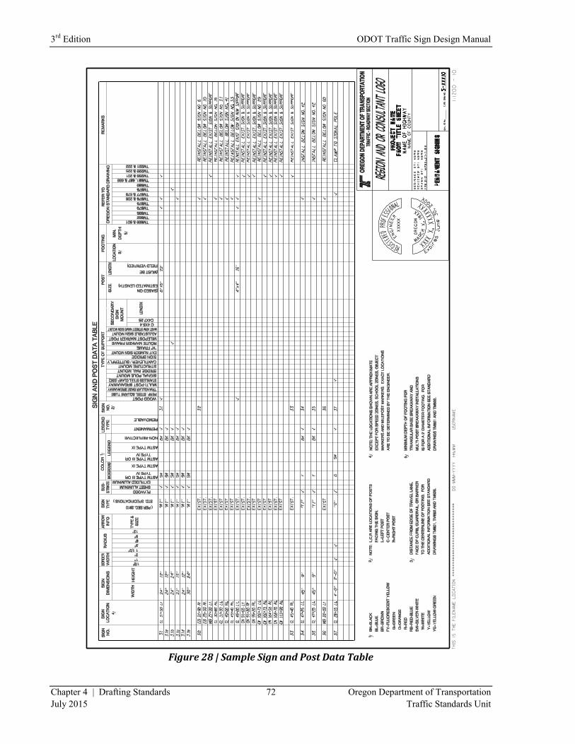
3rd
Edition ODOT Traffic Sign Design Manual
Chapter 4 | Drafting Standards 72 Oregon Department of Transportation
July 2015 Traffic Standards Unit
Figure 28 | Sample Sign and Post Data Table

ODOT Traffic Sign Design Manual 3rd
Edition
Oregon Department of Transportation 73 Chapter 4 | Drafting Standards
Traffic Standards Unit July 2015
Figure 29 | Sample Sign and Post Data Table
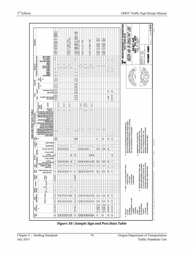
3rd
Edition ODOT Traffic Sign Design Manual
Chapter 4 | Drafting Standards 74 Oregon Department of Transportation
July 2015 Traffic Standards Unit
Figure 30 | Sample Sign and Post Data Table
ODOT Traffic Sign Design Manual 3rd
Edition
Oregon Department of Transportation 75 Chapter 4 | Drafting Standards
Traffic Standards Unit July 2015
Sheet Numbers
All sign plan sheets, sign detail sheets, and sign and post data table sheets require unique sheet numbers
that are assigned by the Traffic-Roadway Section. These unique sheet numbers are used to archive all of
the signing sheets on a project.
Sheet numbers should be requested as close as possible to the printing of final mylars. This is because the
unique sheet numbers run consecutively, and once a set of numbers is assigned it is difficult to simply add
or delete plan sheets from your project. If a sheet needs to be added or deleted after the sheet numbers
have been assigned, often a completely new set of numbers will need to be assigned and the old numbers
voided. Therefore, it is best to request sheet numbers when you are certain that the total number of plan
sheets will not change. This usually occurs sometime between the advanced plans and printing of the
final mylars.
Projects on freeways or expressways or in urban areas will frequently include overhead sign supports,
requiring the production of structural design drawings. If these drawings are for stand-alone supports
such as sign bridges, cantilevers or butterfly supports, then they are to be assigned Signing sheet numbers.
If they are for supports that are attached to a bridge structure, such as structure mounts or bridge rail
mounts, then the drawings are to be assigned Bridge drawing numbers from Bridge Section.
Ideally, structural drawings which are determined to need Signing sheet numbers should be bundled
together with the Signing Plans when sheet numbers are requested. This will take some coordination and
cooperation among the different designers to get it done right. The structural sheets that are related to the
Signing Plans should be positioned immediately after the Sign & Post Data Tables so they can be
assigned numbers that are consecutive with the Signing Plans. All sheets can then be sent in together at
one time as part of a single request from a single party. If they come in separately there are no guarantees
that the numbers assigned will be consecutive. This may seem like a small matter, but it makes a big
difference years down the line when somebody searches our records for “as-built” information. It is
much easier to find information on overhead support structures when the sheets are part of the same run
of numbers as the signing sheets they relate to.
If it is not possible or practical to request these sheet numbers together as one group, then the related
sheets should be cross-referenced to one another. For example, a note might be inserted in the
REMARKS column of the Sign & Post Data Table referencing a particular drawing number for the sign
structure that relates to the subject sign number from the Data Table.
To request sheet numbers for all the plan sheets on the project, call (503) 986-3601 to obtain your sheet
numbers.
Archiving of Files
Once the project has advanced to the bid letting stage the electronic design files should be made available
for archiving. ODOT has its own system of archiving and has a support unit which handles archiving of
all electronic project data. For more information on how to handle archiving of files call the ODOT
Computer Support Desk at (503) 986-3800. They will know how to help provide the process.

3rd
Edition ODOT Traffic Sign Design Manual
Chapter 4 | Drafting Standards 76 Oregon Department of Transportation
July 2015 Traffic Standards Unit
(This page intentionally left blank.)
Chapter 5
Standards
ODOT Traffic Sign Design Manual
3rd Edition
3rd
Edition ODOT Traffic Sign Design Manual
Chapter 5 | Standards 78 Oregon Department of Transportation
July 2015 Traffic Standards Unit
5 | Standards
Standard Drawings and Standard Details
The Standard Drawings which support permanent signing are located in the TM200 and TM600 series of
drawings. These can be accessed through the following web-site link:
http://www.oregon.gov/ODOT/HWY/ENGSERVICES/Pages/traffic_drawings.aspx. Many of these
Standard Drawings have already been discussed for content in the chapter 4 section on Sign and Post Data
Tables. Others not previously mentioned include: TM211 & 212 (Interstate, U.S. and Oregon route
shields); TM221 (Mile post marker signs); TM223 – 225 (Guide signs, conventional and
freeway/expressway); and TM230 – 233 (Demountable legend).
All Standard Drawings which apply to the work described in your plans are to be listed as part of the final
submittal of PS&E documents to the Spec Writer. These are to be listed as “Accompanied By Drawings”
in the lower right corner of the title block on your first plan sheet, just above the sheet number. The Spec
Writer will also include this information in their Index of Sheets which appears just after the Title Sheet.
All sheets listed will be added at the end of the set of contract plans.
Standard Specifications and Special Provisions
Oregon Standard Specifications for Construction (2008) are located at the following web-site:
http://www.oregon.gov/ODOT/HWY/SPECS/standard_specifications.shtml. Most of the specifications
dealing with permanent signing are in Part 00900 – Permanent Traffic Control and Illumination Systems.
There are, however, other portions of this book that relate to signing, as well. For each section of this
book on standard specifications, there is a corresponding document that contains information that is
updated or has been modified or deleted since the publication of the book in 2008. These documents, or
Special Provisions, can be found at the following web-site location:
http://www.oregon.gov/ODOT/HWY/SPECS/Pages/2008_special_provisions.aspx.
Special Provisions, as shown at this web-site are referred to as “boiler-plate” Special Provisions. They
are intended to supplement or supersede the corresponding information shown in the Standard
Specifications.

ODOT Traffic Sign Design Manual 3rd
Edition
Oregon Department of Transportation 79 Chapter 5 | Standards
Traffic Standards Unit July 2015
Any Special Provision that covers an item or a type of work shown in the plans must be included in the
contract documents for that project. Some of the boiler-plate Special Provisions do not actually contain
any updated information, but simply make reference to the corresponding Standard Specification. These
boiler-plate Special Provisions must still be included in the contract documents. In some cases, the
boiler-plate Special Provisions may contain some information that does not apply to a particular project.
In this case, delete that information from the boiler-plate Special Provision before it is submitted to the
Spec Writer. Turn on “Track Changes” before editing boiler-plate special provisions, so the Spec Writer
can see that you have deleted or changed something. If you wish to actually change or add to the content
of the boiler-plate Special Provision, you need to first consult with the “technical resource” of the
Specification. For permanent signing issues, that is the ODOT Sign Engineer, who can be reached at
(503) 986-3603. If the issue is related to structural steel supports or their footings/foundations, then the
technical owner is the ODOT Senior Traffic Structures Engineer, who can be reached at (503) 986-3069.
The boiler-plate Special Provisions most commonly used in conjunction with permanent signing plans are
as follows: Section 840 for projects with milepost marker post installations; Section 905 for projects that
have removals or reinstallations of existing signs and/or supports; Section 910 for projects that have new
wood posts being installed; Section 920 for projects that include installation of sign support footings;
Section 930 for projects that include installation of any of a variety of metal sign supports; and Section
940 for projects including fabrication and installation of new signs. Many of these Special Provisions
refer to other related Special Provisions which must also be included in the final submittal to the Spec
Writer. Among these are Sections 440, 2110, 2190, 2530, 2910 and 2920. There are still other Special
Provisions such as Section 941 (Sign Covers) which apply to items not frequently used on ODOT
contracts.
The Section 160 Special Provision (Source of Materials) has a subsection (160.30) which deals with
agency-furnished materials. Whenever your project includes the installation of certain specialty signs
which are to be provided by ODOT or another agency, then a list of these signs is to be provided in this
subsection along with an indication of where these signs will be delivered. These agency-supplied
materials are usually signs that have a graphic or unique design, and would therefore be difficult for a
sign supplier to reproduce. These are almost always signs which are part of the standard stock at the
ODOT Sign Shop.
Of the permanent signing Special Provisions mentioned above only a few typically require any
modification. In most cases the Special Provision is sufficient in its boiler-plate version. Notable
exceptions are Sections 920 and 930 which contain subsections where the designer is required to list
materials quantities for certain bid items. Other notable exceptions are present in Sections 930 and 940
which contain language specific to painting of metal sign supports and the backs of aluminum substrate
signs. This is generally not done except for under special circumstances, as requested by other agencies
or jurisdictions. Therefore, unless this work has been requested, it is necessary to delete these subsections
from the Special Provisions to insure that the work is not performed.

3rd
Edition ODOT Traffic Sign Design Manual
Chapter 5 | Standards 80 Oregon Department of Transportation
July 2015 Traffic Standards Unit
All Special Provisions pertaining to your design are to be submitted, along with the plan sheets and an
engineer’s estimate showing a breakdown by bid item, to the Spec Writer. This is first done at the
Advance PS&E stage of design. There may be some modification required after the review process, and
the final Special Provisions package will be submitted at the Final PS&E stage. The Special Provisions
are, of course, Word documents and should be submitted electronically. They are typically attached to
and submitted with an Email message.
Chapter 6
Estimates
ODOT Traffic Sign Design Manual
3rd Edition
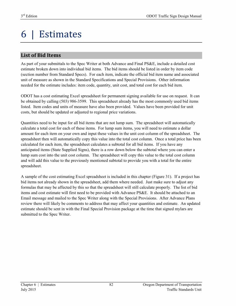
3rd
Edition ODOT Traffic Sign Design Manual
Chapter 6 | Estimates 82 Oregon Department of Transportation
July 2015 Traffic Standards Unit
6 | Estimates
List of Bid Items
As part of your submittals to the Spec Writer at both Advance and Final PS&E, include a detailed cost
estimate broken down into individual bid items. The bid items should be listed in order by item code
(section number from Standard Specs). For each item, indicate the official bid item name and associated
unit of measure as shown in the Standard Specifications and Special Provisions. Other information
needed for the estimate includes: item code, quantity, unit cost, and total cost for each bid item.
ODOT has a cost estimating Excel spreadsheet for permanent signing available for use on request. It can
be obtained by calling (503) 986-3599. This spreadsheet already has the most commonly used bid items
listed. Item codes and units of measure have also been provided. Values have been provided for unit
costs, but should be updated or adjusted to regional price variations.
Quantities need to be input for all bid items that are not lump sum. The spreadsheet will automatically
calculate a total cost for each of these items. For lump sum items, you will need to estimate a dollar
amount for each item on your own and input these values in the unit cost column of the spreadsheet. The
spreadsheet then will automatically copy this value into the total cost column. Once a total price has been
calculated for each item, the spreadsheet calculates a subtotal for all bid items. If you have any
anticipated items (State Supplied Signs), there is a row down below the subtotal where you can enter a
lump sum cost into the unit cost column. The spreadsheet will copy this value to the total cost column
and will add this value to the previously mentioned subtotal to provide you with a total for the entire
spreadsheet.
A sample of the cost estimating Excel spreadsheet is included in this chapter (Figure 31). If a project has
bid items not already shown in the spreadsheet, add them where needed. Just make sure to adjust any
formulas that may be affected by this so that the spreadsheet will still calculate properly. The list of bid
items and cost estimate will first need to be provided with Advance PS&E. It should be attached to an
Email message and mailed to the Spec Writer along with the Special Provisions. After Advance Plans
review there will likely be comments to address that may affect your quantities and estimate. An updated
estimate should be sent in with the Final Special Provision package at the time that signed mylars are
submitted to the Spec Writer.
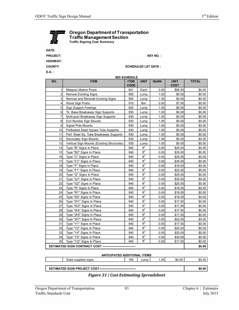
ODOT Traffic Sign Design Manual 3rd
Edition
Oregon Department of Transportation 83 Chapter 6 | Estimates
Traffic Standards Unit July 2015
Figure 31 | Cost Estimating Spreadsheet
DATE:
PROJECT: KEY NO. :
HIGHWAY:
COUNTY: SCHEDULED LET DATE :
E.A. :
NO. ITEM ITEM UNIT QUAN. UNIT TOTAL
CODE COST
1 Milepost Marker Posts 841 Each 0.00 $65.00 $0.00
2 Remove Existing Signs 905 Lump 1.00 $0.00 $0.00
3 Remove and Reinstall Existing Signs 905 Lump 1.00 $0.00 $0.00
4 Wood Sign Posts 910 fbm 0.00 $7.00 $0.00
5 Sign Support Footings 920 Lump 1.00 $0.00 $0.00
6 Tri. Base Breakaway Sign Supports 930 Lump 1.00 $0.00 $0.00
7 Multi-post Breakaway Sign Supports 930 Lump 1.00 $0.00 $0.00
8 Exit Number Sign Mounts 930 Lump 1.00 $0.00 $0.00
9 Signal Pole Mounts 930 Lump 1.00 $0.00 $0.00
10 Perforated Steel Square Tube Supports 930 Lump 1.00 $0.00 $0.00
11 Perf. Steel Sq. Tube Breakaway Supports 930 Lump 1.00 $0.00 $0.00
12 Secondary Sign Mounts 930 Lump 1.00 $0.00 $0.00
13 Vertical Sign Mounts (Existing Structures) 930 Lump 1.00 $0.00 $0.00
14 Type "B" Signs In Place 940 ft2 0.00 $25.00 $0.00
15 Type "B2" Signs In Place 940 ft2 0.00 $35.00 $0.00
16 Type "C" Signs In Place 940 ft2 0.00 $25.00 $0.00
17 Type "C1" Signs in Place 940 ft2 0.00 $35.00 $0.00
18 Type "F" Signs In Place 940 ft2 0.00 $16.00 $0.00
19 Type "F1" Signs In Place 940 ft2 0.00 $22.00 $0.00
20 Type "G" Signs In Place 940 ft2 0.00 $25.00 $0.00
21 Type "G1" Signs In Place 940 ft2 0.00 $35.00 $0.00
22 Type "G2" Signs in Place 940 ft2 0.00 $25.00 $0.00
23 Type "R" Signs In Place 940 ft2 0.00 $16.00 $0.00
24 Type "R1" Signs In Place 940 ft2 0.00 $18.00 $0.00
25 Type "R2" Signs In Place 940 ft2 0.00 $18.00 $0.00
26 Type "W1" Signs In Place 940 ft2 0.00 $17.00 $0.00
27 Type "W2" Signs In Place 940 ft2 0.00 $17.00 $0.00
28 Type "W4" Signs In Place 940 ft2 0.00 $17.00 $0.00
29 Type "W5" Signs In Place 940 ft2 0.00 $17.00 $0.00
30 Type "W7" Signs In Place 940 ft2 0.00 $22.00 $0.00
31 Type "Y1" Signs In Place 940 ft2 0.00 $17.00 $0.00
32 Type "Y2" Signs In Place 940 ft2 0.00 $20.00 $0.00
33 Type "Y4" Signs In Place 940 ft2 0.00 $20.00 $0.00
34 Type "Y5" Signs In Place 940 ft2 0.00 $30.00 $0.00
35 Type "YG" Signs In Place 940 ft2 0.00 $17.00 $0.00
ESTIMATED SIGN CONTRACT COST ----------------------------------- $0.00
State supplied signs 160 Lump 1.00 $0.00 $0.00
ESTIMATED SIGN PROJECT COST--------------------------------------- $0.00
BID SCHEDULE
ANTICIPATED ADDITIONAL ITEMS
Oregon Department of TransportationTraffic Management SectionTraffic Signing Cost Summary
3rd
Edition ODOT Traffic Sign Design Manual
Chapter 6 | Estimates 84 Oregon Department of Transportation
July 2015 Traffic Standards Unit
Providing Quantities
Each of the bid items used for permanent signing falls into one of three categories for payment: 1.) Per
each, 2.) Per unit of measure, or 3.) Lump sum. To determine which of the three applies to a particular
bid item, look in the Standard Specifications and the corresponding Special Provisions for the subsections
defining measurement and payment at the end of the section that deals with that particular bid item.
There will be language specifying how the item is to be measured, to what degree of accuracy, and how it
is to be paid for. Mile post marker posts, for example, are to be paid for per each post. Wood sign posts
are to be paid for per foot board measure (FBM). An individual FBM is to be calculated for each wood
post detailed in the plans and then the sum total of these is provided as the quantity on the cost estimate
for that bid item. FBM is calculated for each post by multiplying the nominal cross-sectional dimensions
in inches and dividing the resulting value by 12. Once this has been done, multiply the new resulting
value by the length of the post in feet to get your number of FBM for that particular post. A 6”x6” post of
20 foot length equals 60 FBM.
Each type of sign is paid for by the square foot. The easiest way to tabulate quantities for these is to go
through each Sign and Post Data Table and calculate a square footage for each new sign by multiplying
together the dimensions (converted to feet). Once this has been completed, tally up a total square footage
for each sign type and these amounts are entered as quantities onto the cost estimate spreadsheet.
Sign (and post) removals as well as removal and reinstallation of existing signs are lump sum bid items.
Although quantities do not need to be provided for either of these items for bid purposes, it is still
necessary to tally up the number of removals and reinstallations for the project so that you can estimate a
lump sum dollar amount to cover this work. For removals, categorize by size of removal, number of
footings involved and whether the sign is ground mounted or overhead. The cost of removal will vary
considerably depending on how large it is, whether there are concrete footings to break up and remove,
and whether special equipment is needed to remove signs from overhead supports. After assigning a
reasonable amount of money for each type of removal or removal and reinstallation, total up the projected
costs and enter them into the appropriate location on the cost estimate spreadsheet.
Sign Support Footings is another lump sum bid item, but unlike sign removals it requires that a quantity
be provided in the Section 920 Special Provision for bid purposes. There are several types of steel sign
supports that require concrete footings.
1. Cantilevers and Sign Bridges require custom design work and their footing quantities
(excavation, concrete, rebar, and backfill) are to be listed individually per location, by the Bridge
Designer. Each of these locations is also listed as a separate bid item for Sign Support Footings
(specifying the type of footing and the location).
2. All ground-mounted steel supports that have footings (Triangular Base Breakaways, Multi-
Post Breakaways, Perforated Steel Square Tube Sign Supports) are combined together as a single
bid item called “Sign Support Footings”. Although a single cost value is entered onto the cost
estimate spreadsheet, the footings for these three types of supports are to be listed separately (by
the Sign Designer) along with their quantities in the Section 920 Special Provision. So if you
have all three types of supports on your project, you will show three separate quantities. These
quantities will show the amount of concrete only (in cubic yards). There is no need to include
amounts for excavation, rebar or backfill for ground-mounted supports.

ODOT Traffic Sign Design Manual 3rd
Edition
Oregon Department of Transportation 85 Chapter 6 | Estimates
Traffic Standards Unit July 2015
To help you calculate concrete quantities, use the material quantity calculation sheets at the following
web-site: http://www.oregon.gov/ODOT/HWY/TS/Pages/signing.aspx#Material_Quantity_Calc__Sheets.
This is an Excel spreadsheet file, but will not make the calculations for you. It simply offers formulas and
steps you through their use. If you click on the tab for “Footing Concrete” you’ll notice that there is no
calculation needed. For each standard size of footing (Triangular Base Breakaways and Multi-Post
Breakaways) there is a corresponding standard amount of concrete in that footing.
By looking at your Sign and Post Data Tables you can tally up a total number of supports estimated for
each type and size of support. Multiplying these numbers by the standard values shown for each
corresponding size and type listed on the spreadsheet and adding the resulting numbers will give you the
quantities (separately for TBBs and MPBs) that you need to show in the Special Provision. In the past
there were no standard values available for the amount of concrete present in a Perforated Steel Square
Tube Sign Support footing, because historically the installation methods varied widely. However, when
installed according to Oregon Standard Drawing TM687 and TM688, the calculated amount of concrete
(by figuring the volume of the excavated hole and subtracting out the volume occupied by the post
anchor) is 0.09 cubic yards. Multiply this resulting amount by the total number of these supports shown
in your data tables to get an estimated quantity for use in the Special Provision. Once you have your
quantities figured for each type, add them together and multiply by an appropriate unit cost for concrete
footings installed.
Except as otherwise stated in the Standard Specifications and Special Provisions (Section 930), list each
type of steel support separately as its own lump sum bid item. Provide quantities of steel (in pounds) in
the Special Provision for estimating purposes. A total quantity for each bid item (type of steel support) is
necessary. Use the same web-site location mentioned above for calculating concrete quantities for
calculating steel quantities. There are calculation sheets for each size of TBB, MPB, and for signal pole
mounts.
After calculating quantities for each individual support, total by type of support and list the resulting
quantities in the Special Provision. Quantities of steel for Perforated Steel Square Tube Sign Supports are
a little tougher to figure, because there are a number of different cross-sectional sizes and varying wall
thicknesses available. Some are designed to break away (slip bases), and some are designed to yield
(anchor tubes). The perforated steel square tube manufacturers can provide information regarding the
unit weight of steel (pounds per lineal foot) for each of the varying sizes and wall thicknesses they
provide. Use these values multiplied by the length of each post and the corresponding sleeve(s) to
calculate a total quantity of steel for each particular installation.
Add all the numbers for each “breakaway” installation to give you a total quantity of steel for all
Perforated Steel Square Tube Breakaway Sign Supports. Likewise, add all the numbers for each
“yielding” installation to give you a total quantity of steel for all Perforated Steel Square Tube Sign
Supports. List these values in the Special Provision for estimating purposes. They are two separate bid
items, so the quantities need to be shown separately.
3rd
Edition ODOT Traffic Sign Design Manual
Chapter 6 | Estimates 86 Oregon Department of Transportation
July 2015 Traffic Standards Unit
Exit Number Sign Mounts are used in pairs. They are most commonly used in 7 foot lengths, but this
may vary depending on the heights of the primary and secondary signs involved. These supports weigh
roughly 5.7 pounds per lineal foot, so it is a simple calculation for figuring the weight of any single pair
of ENSS. Add the weights of all such supports together and place this resulting value in the Special
Provision for estimating purposes.
Structure Mounts and Bridge Rail Mounts are custom designs provided by a structural designer. That
individual is responsible for providing quantities for bidding purposes on these items. Likewise for
cantilevers and sign bridges, except that the quantities for these are to be listed separately and shown as
separate bid items for each individual location. After estimating quantities for each steel bid item, select
appropriate unit costs (per pound installed) for each type of steel in order to calculate a lump sum cost
estimate for each item.
Unit Costs and Regional Factors
Historical data is available from ODOT Cost Estimating Unit on their web-site at
http://www.oregon.gov/ODOT/HWY/ESTIMATING/bid_item_prices.shtml. This site has data available
with either a statewide or a regional focus. This data compiles bid prices submitted for projects dating as
far back as 1998. Bid items are listed by the section number (2008 Oregon Standard Specifications for
Construction) within which they fall. For example, wood sign posts are listed by the number 0910 since
they are covered by Section 910.
Costs for certain bid items will vary some from region to region. Focus on the data available within your
specific region of the state for the past 2-3 years. If there is not much data available within your region,
look at the data available within an adjacent region or, if necessary, from the statewide listings. For items
bid per each or per unit of measure, good cost figures should be available for putting together a cost
estimate. Others bid as lump-sum items are more difficult to borrow data from, because the only
historical data available are the actual lump-sum bid amounts which do not indicate the quantity of
material covered by the bid mount.
If you are having trouble coming up with good cost figures for use in estimating, contact our ODOT
Traffic Standards Unit at (503) 986-3599 for assistance.
Anticipated Items
When your project includes signs with unique, hard to reproduce, graphic features such as Scenic Byway
signs, Tour Route signs, Historic Columbia River Highway, Lewis and Clark Trail, Oregon Trail, and
State Parks Shields, you may wish to note them on the plans as “State Supplied Signs”. This is because
these signs could prove difficult for some sign suppliers to accurately reproduce, and the signs are readily
available through ODOT’s Sign Shop.
If you decide to call out for State Supplied Signs, then it should be noted as such on the Sign Details sheet
next to the applicable sign(s) and in the “Remarks” column of the Sign and Post Data Table. In the
Special Provisions (00160.30), list the items supplied, including the number and size of each type of sign.
ODOT Traffic Sign Design Manual 3rd
Edition
Oregon Department of Transportation 87 Chapter 6 | Estimates
Traffic Standards Unit July 2015
At the bottom of the bid item/estimate spreadsheet enter a dollar amount that will cover the purchase and
installation of these signs. This “Anticipated Item” amount enables the Project Manager to purchase the
signs from the State Sign Shop when needed and to have them delivered to the contractor at the job site
for installation. The amount provided should cover the cost of installation by the contractor as well as the
purchase price of the signs. There may be occasions where anticipated items are necessary to cover items
other than State Supplied Signs, but they are not very common.
When an Anticipated Item is used, justification is needed to support this decision. There is a process to
follow for providing this justification in writing. The Cost Estimating Unit web-site offers a couple of
letter templates that are required submittals within this process. First is the Letter of Approval for
Anticipated Items. The second is the Letter of Public Interest Finding. These letter templates can be
accessed through the following link:
http://www.oregon.gov/ODOT/HWY/ESTIMATING/Pages/manuals_forms_etc.aspx#Templates.

3rd
Edition ODOT Traffic Sign Design Manual
Chapter 6 | Estimates 88 Oregon Department of Transportation
July 2015 Traffic Standards Unit
(This page intentionally left blank.)
Chapter 7
Design Follow-Up
ODOT Traffic Sign Design Manual
3rd Edition
3rd
Edition ODOT Traffic Sign Design Manual
Chapter 7 | Design Follow-Up 90 Oregon Department of Transportation
July 2015 Traffic Standards Unit
7 | Design Follow-Up
Construction Support
Your part of getting the project out to bid is now completed, providing that your plans, specs, and
estimate are clear enough that any of the bidders don’t have questions about them. Usually, all the
questions that the bidders have are directed to the Project Manager that will be overseeing the contract. If
he gets a question on part of your work that he can’t answer, he will contact you for an answer. Keep a
copy of all the documents you submitted close to your desk until the bid is opened.
After the bid is opened, send a copy of all the Sign Drawings to the Project Manager and the Materials
Inspection Section. The Sign Drawings will be used to actually build all of the non-standard signs on the
project.
Sometimes unexpected things occur as part of construction. It is not unusual to get a call from the Project
Manager asking for a design for a sign that has been hit by a vehicle and destroyed. Sometimes signs
disappear off the project and will need replacing. These requests require immediate attention since time
is very critical. The permanent signing is one of the last things to happen as part of a contract; the
Contractor may be looking at liquidated damages if they run over the scheduled contract completion date.
You will also have to answer questions about the location of sign placement. There are places in the state
that have very little soil cover over solid rock and the Contractor will want to move the sign placement to
allow for drilling the sign footing hole. Be aware of proper sign distances when you allow signs to be
moved. Do not approve moving a sign if it violates sign spacing requirements. If moving the sign is
required, you may have to move the location of several signs to accommodate one installation. You can
also explore placing more than one sign at a given place, but do not overload the driver with too much
information on a single installation.
You may also be requested to change the type of support that a sign was designed to receive. Some of
these requests make good sense and should be approved. Be careful that you have a bid item for the new
support or have the Project Manager write a Contract Change Order (CCO) to accommodate the new
support. Since at the time of design, you cannot be aware of what is occurring or what will occur before
the sign is installed, be flexible in allowing changes. Moving a sign to a Signal Pole Mount to avoid
blocking a new commercial sign would be a good example of things that occur that you cannot anticipate.
Shop Drawings / Submittals
Sign designs for typical MUTCD signs and standard Oregon signs can be found in the FHWA Standard
Highway Signs Manual (See Appendix B) and the Oregon Sign Policy & Guidelines for the State
Highway System (See Appendix B). Signs that appear in these books do not require shop drawings since
the designs are already available.
ODOT Traffic Sign Design Manual 3rd
Edition
Oregon Department of Transportation 91 Chapter 7 | Design Follow-Up
Traffic Standards Unit July 2015
Signs
Material submittals (shop drawings) for non-standard signs will be needed by the sign fabricator prior to
fabrication. Section 940 of the 2008 Oregon Standard Specifications for Construction requires the
Engineer of Record to supply these to the contractor upon request. The request will usually come from
the Project Manager’s office. The designer provides the Project Manager with enough copies of shop
drawings for each non-standard sign to insure that all interested parties receive copies. This includes the
Project Manager, Prime Contractor, Signing Sub-Contractor, and the Sign Supplier (fabricator). A single
set of shop drawings also must be sent to the ODOT Materials Inspection Unit in Portland for use in
inspecting and approving of the signs upon fabrication. Larger sets should be mailed, while smaller sets
can be faxed to (503) 653-3085.
Shop drawings for non-standard signs are most easily produced at the same time as the Sign Detail sheets.
Since the Guidsign sign design software is necessary to design these signs for the data tables, it only
requires a few more steps to create a report for each sign. ODOT users have a custom sheet style and
report form set up for shop (contract) drawings within the Guidsign program. It shows the following
information on an 8½” x 11” print for each individual sign: Project name, sign number, dimensions,
border width, corner radius, color and type of background sheeting, color and type of legend, sign type,
substrate material, and number required. Each sheet also shows a to-scale likeness of that particular sign
along with detailed dimensioning for all pieces of legend and the spacing in between. There is a spacing
chart included which specifies positioning for each individual letter, shield or arrow based on an x-y
coordinate system. The program fills in most of this information automatically, but some text may need
to be modified manually. Be sure to keep a complete set of these drawings for yourself. You may need
to refer to them occasionally when called by an inspector or fabricator.
Quite often things change between the project design and the project construction. Things can change
during construction also. The designer must occasionally add or subtract signs from the project. The
final decision on adding or subtracting signs lies with the Engineer of Record (the person who stamped
and signed the plans) since they are legally responsible for the signing installed according to the plans. If
a decision to add or subtract signs is made, notify the Material Inspection Unit as soon as possible. If you
send out sign designs for added signs to the project, fax a copy of the design to the Material Inspection
Section. Otherwise they will not know there are additions and will call you for verification before they
approve the signs at the sign manufacturing location. Include changes to the plans in the As-Constructed
drawings made after the project is completed.
Steel Supports
Since the lengths of all the sign supports are estimated in the design stage, a field verification of the sign
supports is necessary before the sign supports are ordered. Typically field verification of the wood posts
and perforated steel square tube sign supports are done at the Project Managers office and you will never
see them. Occasionally, they send them in for verification. A list of verified post lengths is given to the
Contractor so they can order the right size posts before showing up on the project (most permanent
signing is done by a sub-contractor).

3rd
Edition ODOT Traffic Sign Design Manual
Chapter 7 | Design Follow-Up 92 Oregon Department of Transportation
July 2015 Traffic Standards Unit
Sign supports specified for Multi-Post Breakaway (MPB) and Triangular Base Breakaway (TBB) sign
supports also need to be verified by the designer prior to fabrication, based on cross-sectional information
provided by the Project Manager’s office. The cross-sections are taken at the actual locations specified in
the Sign and Post Data Tables, and then they are sent to the designer. The designer calculates the actual
post size at this time and fills out a sign post drawing for that particular size and type of support.
Use the Excel spreadsheet design programs mentioned earlier to determine the actual sizes and lengths
needed for each support. Blank forms for all the standard sizes of Multi-Post Breakaways and Triangular
Base Breakaways (with or without “H” frames) are available from the ODOT Traffic Standards web-site
at the following link:
http://www.oregon.gov/ODOT/HWY/TS/Pages/signing.aspx#Steel_Support_Shop_Drawings.
Other forms are available at this same location for signal pole mounts and secondary sign supports (Exit
Number Sign Mounts, route marker frames, “C” channels). These other forms do not require any cross-
sectional information to complete. Once you have completed all of the necessary steel shop drawings,
copy enough extra sets to cover all interested parties.
Provide sets for the Project Manager, Prime Contractor, Signing Sub-Contractor, and Steel Fabricator.
Send these to the Project Manager to be forwarded. It is likely that the original request for drawings will
come through that office. Keep an extra set for yourself in case of phone inquiries.
The Contractor will have the posts fabricated to the information shown on these drawings. This ensures
that the proper size and length of support is used for each sign installation. The contractor should not
begin fabrication of any steel supports until they are provided shop drawings from the Engineer of
Record.
Shop drawings are not necessary for the following types of metal sign supports: perforated steel square
tube sign supports, milepost marker posts, adjustable sign mounts, and mast arm street name sign mounts.
Any shop drawings required for cantilevers, sign bridges, structure mounts or bridge rail mounts are to be
provided by the structural designer responsible for their design.
Chapter 8
Special Design Considerations
3rd Edition
ODOT Traffic Sign Design Manual
3rd
Edition ODOT Traffic Sign Design Manual
Chapter 8 | Special Design Considerations 94 Oregon Department of Transportation
July 2015 Traffic Standards Unit
8 | Special Design Considerations
Review Requirements for Interstate Signing
The uniform appearance and application of signing on the Interstate Highway System is critical. Since
2003, concerns and problems on projects designed on the Interstate have elevated the importance of
taking steps to assure that there is a level of quality control implemented in the review of installations for
Interstate signs. Because the cost of fixing potential mistakes is more extensive on the Interstate, and
because providing guidance to designers needs to be done in a timely manner to avoid conflicts with
project deadlines, a set of Interstate review requirements has been established.
Project Delivery
For all STIP or construction projects with proposed changes to permanent signing on the Interstate
Highway system the following review steps are required:
DAP Review
Sign Designers submit preliminary plans through the Region Traffic Office to the Traffic
Standards Unit.
Plans will include the locations, sign content (text & symbols), estimated sizes, and anticipated
support requirements for all new or revised signs. See Appendix C for further details.
The Traffic Standards Unit shall review and make comments on the submitted preliminary
signing plans within ten business days of receipt.
Advance Plan Review
Advance signing plans shall be submitted through the Region Traffic Office to the Traffic
Standards Unit along with shop drawings prior to the Plans in Hand review for the project. See
Appendix C for further details.
Any discrepancies between designers concerns and review comments shall be resolved prior to or
as part of the Plans in Hand review.
If a design project does not have a Plans in Hand review as part of its project schedule, the Sign
Designer shall submit the plans (with the sign shop drawings) 4 weeks prior to Final Plans for
review and acceptance by the Traffic Standards Unit. The Traffic Standards Unit will reply with
comments within ten business days.
ODOT Traffic Sign Design Manual 3rd
Edition
Oregon Department of Transportation 95 Chapter 8 | Special Design Considerations
Traffic Standards Unit July 2015
Maintenance Sign Changes and Additions
Any modifications to non-standard signs on the Interstate as part of maintenance activities must be
designed by a sign designer and approved by the Traffic Standards Unit. According to the following
steps:
Sign designers will submit plans showing sign content, location, size, support and sign shop
drawings to the Traffic Standards Unit for review and approval
The Traffic Standards Unit shall review and make comments back to the designer on the
submitted designs within one week
The Traffic Standards Unit will indicate final approval by sending an E-Mail to the sign designer
that indicates the sign designs that have been approved
Non-standard signs, for the purpose of this manual, shall be considered any sign design not
detailed by a sign design included in the FHWA Standard Highways Signs Manual or the Oregon
State Sign Policy and Guidelines Manual.

3rd
Edition ODOT Traffic Sign Design Manual
Chapter 8 | Special Design Considerations 96 Oregon Department of Transportation
July 2015 Traffic Standards Unit
(This page intentionally left blank.)
Appendices
3rd Edition
ODOT Traffic Sign Design Manual
3rd
Edition ODOT Traffic Sign Design Manual
Appendix A | Signing Contacts 98 Oregon Department of Transportation
July 2015 Traffic Standards Unit
Appendix A | Signing Contacts
Before starting the design, a designer may find it beneficial to assemble a list of personal contacts
involved in individual aspects of the project. The following is a list of position titles that may be useful to
add to the contact list for any given project. Along with each position is some insight into how that
person may be of benefit to you as a contact. The names and phone numbers that correspond with these
positions can be obtained from the appropriate ODOT Region Tech Center in your area of service.
Project Leader / Consultant Project Manager
The Project Leader or Consultant Project Manager will provide you with information about project scope
and plan format. They can tell you information about the design schedule and the critical project
deadlines. This person will also coordinate design resources that you might need, such as a sign
inventory or photos. They should be able to provide you with the names of many of the other contacts,
included below, for your specific project.
Roadway Designer
The roadway designer will provide all CADD files necessary to begin your own design. They provide
files for existing features, new construction, right-of-way, alignments, etc... They also provide
information about project scope and plan format. The roadway designer will be responsible for
preliminary plans distribution.
Specification Writer
The specification writer is responsible for assembling the Plans and Specifications from each of the
project disciplines and creating a single set of contract documents. The specification writer doesn’t
typically get involved in the project until after the Preliminary Plans phase and just prior to the Advance
Plans and Specifications phase. You submit your Plans and Specifications to the specification writer for
both Advance Plans and Specifications and Final Plans and Specifications. They distribute the Plans and
Specifications for review. If you need to add any unique language to the boiler-plate special provisions,
the changes need review and approval by the specification writer and the technical resource for that
specification.
Region Sign Designer
Each Region has a designer responsible for the sign designs created in the Region. They can answer
questions about design standards and signing policy. Each Region also has either a Region Traffic
Manager or a Region Traffic Engineer. Contact information for current Traffic Managers and Traffic
Engineers is available at the ODOT Highway Regions website:
http://www.oregon.gov/ODOT/pages/highwayregions.aspx.
ODOT Traffic Sign Design Manual 3rd
Edition
Oregon Department of Transportation 99 Appendix A | Signing Contacts
Traffic Standards Unit July 2015
Traffic-Roadway Section Staff
The Traffic-Roadway Section staff provides technical assistance on signing issues for ODOT design staff
as well as consultants and local agencies. TRS staff publishes the Traffic Sign Design Manual and the
Sign Policy and Guidelines. TRS staff also maintains As-Constructed Plans, speed zone orders and no
parking resolutions, and provides sign designs for specialty signs. TRS staff maintains a web-site that
offers a number of other resources for designers. TRS staff also provides the sheet numbers for all
contract signing plans. The Traffic-Roadway Section maintains a website at:
http://www.oregon.gov/ODOT/HWY/TRAFFIC-ROADWAY/.
District Sign Supervisor/Coordinator
The district sign supervisors and district sign coordinators are responsible for maintenance of all state-
owned signs and supports within their maintenance district. These Supervisor/Coordinators maintain
databases of their entire sign inventory within their district. The databases provide the designer with
useful information to serve as a supplement to the project sign inventory and photos. The
Supervisor/Coordinators can provide information as to the age and/or condition of existing signs and
supports. They can also provide comments during the plan review process.
State Parks
Oregon State Parks and Recreation has an individual contact who can be reached at (503) 986-0707. The
designer should contact this individual for guidance pertaining to the design of new signing or the
replacement of existing signing for State Parks facilities. This contact should also be included in the plan
review process for any project that contains State Parks signing.
Oregon Travel Experience (OTE)
The Oregon Travel Experience (formerly the Travel Information Council) owns and maintains all TODS
(Tourist Oriented Directional Signs) and LOGOS (Motorist Informational Signing) on our state highway
system. They are to be notified about any work on our system that will in any way impact their signs.
They should also be contacted about any TOD or LOGO signs that are affected by work zone staging.
The designer should include them in the plans review distribution, and invite their comments as to the
appropriateness of any planned activities that will affect their signs. OTE also has ownership of signing
programs affecting resort areas, museums, and private golf courses. Their staff can be reached at (503)
378-4508. OTE maintains a website at: http://ortravelexperience.com/.
Right-of-Way
The Region right-of-way office will need detailed information from the sign designer pertaining to any
right-of-way or easement needs necessary to accommodate permanent signing installations on the project.
They can also provide you with accurate right-of-way CADD files if the roadway designer is not able to
do so.

3rd
Edition ODOT Traffic Sign Design Manual
Appendix A | Signing Contacts 100 Oregon Department of Transportation
July 2015 Traffic Standards Unit
Sign Structures Designer
You may need to request custom design assistance from a structural designer for a number of different
types of steel sign supports. Some of these are covered by standard drawings. Others such as bridge rail
mounts, structure mounts, cantilevers and sign bridges will require custom designs. The sign designer
will need to provide detailed information, as to the size and location of these signs, for the sign structures
designer to be able to complete their design. The sign designer will also want to make reference in their
signing plans to these structure designs.
Geotechnical Engineer
The sign designer should contact the geotechnical engineer for help determining foundation exploration
needs for overhead supports. The geotechnical engineer can help with scheduling of any drilling and
testing of soil samples.
Landscape Designer
If landscape design work is included in the project, the landscape designer should be contacted to ensure
that no elements of their design will conflict with the signing plans. It is not uncommon for landscape
plans to include trees at or near locations where signing is needed. Those trees will eventually grow out
and block the view of nearby signs.
Other Traffic Designers
These could include signal, striping, illumination or traffic control plans designers. The sign designer
may need to coordinate plans with any or all of these individuals to ensure that there are no conflicts with
each other’s plans, such as a sign to be installed behind a luminaire pole or a DO NOT PASS sign to be
installed at a location that conflicts with the striping plans. Signing plans should often make reference to
other plans, such as referring to a signal design sheet for details about signs that need to be mounted on
signal poles. Communicating this information with other designers is important to them, as well. For
example, the signal designer will need to know about any signs to be mounted on their signal poles so that
they can design the pole to satisfy all loading requirements.
Project Manager (and Inspector)
The Project Manager or Project Inspectors may contact the sign designer at various times throughout
project development and construction for clarification about plans, questions about contract change orders
and price agreements, and many other issues. The sign designer provides them with technical assistance
when needed. The sign designer also provides working drawings for fabrication of non-standard (custom)
signs, steel sign supports, secondary supports, and route marker frames. The sign designer provides them
to the Project Manager upon request. They, in turn, forward copies to the fabricators for manufacture.
The Project Manager needs to provide the sign designer with cross-sectional information to assist the sign
designer in calculating final steel post sizes and lengths included in the working drawings.
ODOT Traffic Sign Design Manual 3rd
Edition
Oregon Department of Transportation 101 Appendix A | Signing Contacts
Traffic Standards Unit July 2015
Bicycle & Pedestrian Program Manager
The Bicycle & Pedestrian Program Manager sets policy and standards for handling of bicycle and
pedestrian issues and for matters relating to design of bicycle and pedestrian facilities. Call (503) 986-
3554 with any questions about the effectiveness of existing or proposed signing as it relates to bicycle and
pedestrian facilities. This could involve signing for bike lanes, bike paths, multi-use paths, etc.
Construction Materials Inspection Lab
The ODOT Construction Materials Inspection Lab is responsible for inspecting custom sign designs that
have been fabricated for ODOT construction projects. Sign designers should make sure to provide copies
of their shop drawings to the Construction Materials Inspection Lab.
Survey Crew
The Survey Crew inventories the existing signing as they are doing the topographical survey of the
project. It is a good idea to contact survey crew members to help them understand the information that
needs to be collected.
Appendix B | Sign Design Resources 102 Oregon Department of Transportation
July 2015 Traffic Standards Unit
Appendix B | Sign Design Resources
In addition to your list of contacts, you will need access to a number of different resources to aid you in
the development of Plans and Specifications. The following paragraphs describe a number of these
resources. Some include computer links where they can be accessed or phone contacts. This is not
intended as a complete list of every resource necessary, but it includes those needed regularly for most
designs.
Existing Sign Inventory & Photos
In order for a designer to produce a complete set of permanent signing plans, a sign inventory of the
existing sign installations is required. The inventory can be obtained in several different ways.
The best and most complete inventory is obtained when the survey crew inventories the existing signing
as they are doing the topographical survey of the project. The exact location of the signs can be
determined and mapped into the project plans.
The Highway Design Manual (2012 Version, Chapter 11) explains roadside inventory needs for the
various classifications of projects (1R, 3R, 4R). The web-site for this manual can be accessed at:
http://www.oregon.gov/ODOT/HWY/ENGSERVICES/Pages/hwy_manuals.aspx.
Digital Video Log
Another option for obtaining information for the sign designer to use is the digital video log. This method
requires a lot of guessing on the part of the designer because they consist of digital photos snapped every
.005 mile (roughly 25 feet). Exact sizes of signs and supports are nothing more than guesses on the part
of the designer. This method combined with a sign database from some District Sign Crews is the least
desirable of the methods mentioned. The online version of the digital video log can be found at two
locations. An intranet version is available to ODOT employees at:
http://intranet.odot.state.or.us/cf/dvl/index.cfm.
An internet version is also available at:
http://www.oregon.gov/ODOT/TD/TDATA/pages/rics/videolog.aspx.
Manual on Uniform Traffic Control Devices (MUTCD)
State Law requires that all traffic control devices placed on highways in Oregon be in compliance with
the MUTCD and Oregon Supplements to the MUTCD (OAR 734-020-0005). Signs placed on the state
highway system should comply with the Sign Policy and Guidelines for the State Highway System.
Existing signs and supports need to be reviewed for compliance with the current MUTCD. Once the
Oregon Transportation Commission adopts a new version of the MUTCD, all traffic control devices
placed in service from that date forward must comply with the MUTCD.
ODOT Traffic Sign Design Manual 3rd
Edition
Oregon Department of Transportation 103 Appendix B | Sign Design Resources
Traffic Standards Unit July 2015
A list of compliance dates for the Manual on Traffic Control Devices can be found at:
http://mutcd.fhwa.dot.gov/kno-compliance.htm.
The MUTCD can be accessed on-line at: http://mutcd.fhwa.dot.gov/pdfs/2009r1r2/pdf_index.htm. There
are links at this site that will take you to other sites where you can order the manual or you can download
the entire manual.
Standard Highway Signs Manual
This site also has a link to the “Standard Highway Signs (SHS)” book that contains sign layouts for
almost all the signs shown in the MUTCD. You can also go directly to that site at:
http://mutcd.fhwa.dot.gov/ser-shs_millennium.htm
Oregon Supplements to the MUTCD
The Oregon Supplements to the MUTCD can be accessed on-line at the Traffic-Roadway Section web
site at:
http://www.oregon.gov/ODOT/HWY/TRAFFIC-ROADWAY/Pages/mutcd.aspx
Sign Policy & Guidelines for the State Highway System
The Sign Policy and Guidelines manual can be accessed on line at:
http://www.oregon.gov/ODOT/HWY/TRAFFIC-ROADWAY/sign_policy.shtml.
From this site you can download individual chapters or the entire manual. This manual contains
information that supplements or, in some cases, takes exception to the information in the MUTCD. The
Sign Policy is an ongoing document usually updated several times a year to keep up with current changes
in policy. The most recent updates are available for downloading at the site previously mentioned.
ODOT Traffic Manual
The ODOT Traffic Manual provides designers with information regarding the traffic policies, practices,
and organization within ODOT. It has information on different roles and responsibilities within different
Sections of ODOT as well as providing information that may be necessary when considering changes in
traffic control. It also includes information on where to look up specific policies, procedures, warrants,
and design consideration for traffic items. The ODOT Traffic Manual is available online at the following
website:
http://www.oregon.gov/ODOT/HWY/TRAFFICROADWAY/publications_traffic.shtml
3rd
Edition ODOT Traffic Sign Design Manual
Appendix B | Sign Design Resources 104 Oregon Department of Transportation
July 2015 Traffic Standards Unit
Speed Zone Orders
You will need to obtain any existing Speed Zone Order(s) for the sections of highway included inside the
limits of your project. Speed Zone Orders are official documents that set out the limits of speed zones
that are different than the statutory speeds listed in state law. Over the years, they have been approved by
the Oregon Transportation Commission, State Highway Engineer, State Speed Control Board, Speed
Zone Review Panel and the State Traffic Engineer.
The Speed Zone Order can be obtained through the Traffic-Roadway Section by calling 503-986-3571.
You will need the name of the Highway and the mile point limitations of the project to give to the person
answering the phone. New Speed Zone Orders do not necessarily contain School Speed 20 information.
This may have to be obtained from the road authority.
Any new speed zone sign installations shown on your plans must be consistent with the speeds and
locations as spelled out in the Speed Zone Order(s). Existing installations that are located improperly or
are otherwise inconsistent with the Order must be corrected. This is necessary in order to allow for
proper enforcement.
Use the following website to review Speed Zone Orders online:
http://www.oregon.gov/ODOT/HWY/TRAFFIC-
ROADWAY/pages/speed_zone_program.aspx#Speed_Zone_Orders_On_Line.
No Parking Resolution
You will need to check for any No-Parking Resolution for the state highway. These can be obtained from
the Traffic-Roadway Section by calling 503-986-3604. You will need to provide the name of the
highway and the mile point limits of the project.
On City streets and County roads, the local jurisdiction controls the no-parking sections of roadway.
Usually, the Public Works Department can get this information for you.
No-Parking Resolutions are similar to Speed Zone Orders in that the signing in the field must reflect the
language of the Resolution in order to allow for proper enforcement. If “No Parking” signing is present
in a location not covered by No-Parking Resolution, it is there illegally and should be removed.
Signing which permits on-street parking in urban areas is allowed on our highway system, but it is the
responsibility of the local jurisdiction to set the limits and to install, maintain and enforce the signing.
ODOT Traffic Sign Design Manual 3rd
Edition
Oregon Department of Transportation 105 Appendix B | Sign Design Resources
Traffic Standards Unit July 2015
Contract Plans Development Guide
This is a two volume document that provides the designer with all the technical information, such as
standards and drafting standards, to produce plans that will be bid through a Transportation Commission
Services Contract. This document can be obtained on-line at:
http://www.oregon.gov/ODOT/CS/CONSTRUCTION/Manuals.shtml
There is a charge for this publication.
Standard Specifications and Special Provisions
The Oregon Standard Specifications for Construction (2008) book can be obtained on-line at:
http://www.oregon.gov/ODOT/HWY/SPECS/standard_specifications.shtml
These Standard Specifications are supplemented by our Special Provisions. The most current edition of
our Special Provisions can be found on-line at:
http://www.oregon.gov/ODOT/HWY/SPECS/Pages/2008_special_provisions.aspx
Standard Drawings
Oregon Standard Drawings can be accessed on-line at:
http://egov.oregon.gov/ODOT/HWY/ENGSERVICES/traffic_drawings.shtml. Standard Drawings
pertaining to permanent signing are located in the TM200 drawing series. Standard Drawings pertaining
to structural steel sign supports can be found in the TM600 drawing series.
As-Built Plans
ODOT Traffic-Roadway Section maintains sets of “As-Built” plans as we receive them from our
construction field offices. These As-Builts have not been completed for all projects that included
permanent signing, but we do keep those that we receive on file. They can prove useful at times in the
absence of a good sign inventory and photos. They can also provide information such as overall sign
dimensions and letter sizes used on guide signs, especially those that are overhead and otherwise hard to
measure in the field. As-Built plans should not be relied on for accuracy if more than 10 years old.
Anything older than that have a strong possibility that those signs and/or supports may have already been
replaced through normal maintenance activity. If this has happened, there is no guarantee that they were
replaced with something of like size. It is always better to get actual field data on-site, whenever
possible. As-Builts should be considered as a last resort for inventory purposes. Inquiries about our As-
Builts should be directed to (503) 986-3599.
3rd
Edition ODOT Traffic Sign Design Manual
Appendix B | Sign Design Resources 106 Oregon Department of Transportation
July 2015 Traffic Standards Unit
Oregon Bicycle and Pedestrian Plan
The Oregon Bicycle and Pedestrian Plan contains a lot of good information about design and maintenance
of bicycle and pedestrian facilities. There is a section which focuses on appropriate and inappropriate
signing for bicycle facilities, whether they are located on the state highway system or off the highway
system. The Oregon Bicycle and Pedestrian Plan can be found on the ODOT web-site at the following
location: http://egov.oregon.gov/ODOT/HWY/BIKEPED/planproc.shtml.
OARs and ORSs
Oregon Administrative Rules (OARs) and Oregon Revised Statutes (ORS) provide important guidance in
the use of permanent signing. Enforcement of many traffic signs and the associated fines are governed by
the laws that they are established under. It is important to try and use sign language defined by statute
and the appropriate fines established. Oregon Administrative Rules are found online at:
http://arcweb.sos.state.or.us/banners/rules.htm
Oregon Revised Statutes are found online at:
http://www.leg.state.or.us/ors/
Qualified Products List
The Qualified Products List (QPL) is a comprehensive list of all finished products which have been
evaluated by ODOT for use on state highways. Sign designers are frequently asked by district crews and
region traffic to look into implementing new products on the State Highway System. It is important to
check with the QPL to ensure that products have been approved. New products that do not show up on
the list can be referred to the ODOT Materials Laboratory for possible acceptance. The list of approved
products can be found online at:
http://www.oregon.gov/ODOT/HWY/CONSTRUCTION/QPL/qpindex.shtml
Traffic Control Devices Handbook
The Traffic Control Devices Handbook is a publication produced by the FHWA intended to augment the
information from the MUTCD. The Traffic Control Devices Handbook links the standards and warrants
of the MUTCD with the activities related to complying with the standards. The most recent update to the
Traffic Control Devices Handbook was completed in 2001. The document is not available online, but can
be purchased through several different traffic related organizations.

ODOT Traffic Sign Design Manual 3rd
Edition
Oregon Department of Transportation 107 Appendix B | Sign Design Resources
Traffic Standards Unit July 2015
Interstate Highways Control Cities List
This list is an AASHTO publication formally entitled “List of Control Cities for Use in Guide Signs on
Interstate Highways”. Control Cities are major destinations along an interstate route, as determined by
AASHTO, with input from each of the states. These Control City legends should be used in the following
situations, along a freeway, to provide for consistency and continuity in directional guide signing: 1.)
Interchanges between freeways; 2.) Separation points of overlapping freeway routes; 3.) On directional
signs on intersecting routes, to guide traffic entering the freeway; 4.) On Pull-Through signs; 5.) On the
bottom line of post-interchange distance signs. This list can be found online at:
http://home.roadrunner.com/~pwolf/controlcities.html

Oregon Department of Transportation 108 Appendix C | Level of Development
Traffic Standards Unit July 2015
Appendix C | Level of Development
Design Acceptance Package
The Design Acceptance Package (previously known as Concept Plans) is not a standard part of all ODOT
projects. Instances when it would be appropriate include projects with complicated geometric design
such as freeway and expressway projects involving grade separation and interchange ramps. These
projects will usually require the use of large overhead guide signs. For situations such as this, the earlier
you can identify major signing needs the better. Installations that will require the purchase of right-of-
way or that will require overhead structural support design should be identified early on so that others
affected (right-of-way agents, structural designers, foundations exploration crew) can have plenty of time
to complete their work within the overall project schedule. At this early stage, you would likely only
need to provide Signing Plan and Sign Details sheets to show location and type for major guide signs. A
rough estimate of permanent signing costs might be warranted particularly where overhead supports will
be required, as these are quite expensive in comparison to typical ground-mounted sign installations.
Preliminary Plans
The usual items to be completed for the Preliminary Review would be the Signing Plan Sheets, Sign
Detail Sheets, and the completed Sign and Post Data Table sheets. The Specifications, Special
Provisions, and Estimate are usually completed with the Advance Plans but one or more of these items
may be requested on occasion at the preliminary plans stage. If you are pressed for time, it is acceptable
to send out Preliminary Plans without the Sign and Post Data Tables completed. Although it would be
better to include them, the most important information to show at this time is the type of signs and
supports and where they are going. This can be accomplished with the Signing Plans and Sign Details
only. It is not uncommon for major changes to be made as part of the Preliminary Plans review so you
may be wasting time if you prepare specs and estimate at this design stage. You will want to wait until
later in the process, if possible, for specs and estimate to ensure that you have thoroughly covered all
items in your plans.
The Preliminary Plans are usually submitted to the Roadway Designer for review distribution. You can
request that the Road Designer send copies of the package to additional parties. The preliminary plans
should be sent to the District Manager and the District Sign Crew for review. Make sure these people are
included in the distribution list, as they are not always automatically listed. Remember that these are the
people that will be maintaining the product. The District Sign Crew review is very important as they
know what signs are in the field and what kind of condition they are in. Depending on who is impacted
by the project, you may want to send plans to Oregon Travel Experience (required when logo or specific
service signs are impacted), State Parks and Recreation, National Park Service, US Forest Service, etc. If
you find out about a entity that needs a set of plans after the distribution is sent out-go to the Contractor
Plans unit, get a set of plans and mail them to that party. The more review you can get from the plans, the
better set of plans you can produce.
This would be the time to have your plans reviewed by another sign designer if you have one available.

ODOT Traffic Sign Design Manual 3rd
Edition
Oregon Department of Transportation 109 Appendix C | Level of Development
Traffic Standards Unit July 2015
You should start receiving comments back from people within a few days. Take the time to review all the
comments to see if they apply to this situation. A note back to the person submitting the comments is
sometimes in order-especially if you are choosing not to incorporate the changes requested.
Advance Plans and Specifications
After you have received the comments on your Preliminary Plans, check with the Roadway Designer on
your project to see if there are any changes in the Roadway Plans. Quite often, the Roadway Designer
will change alignment, stationing, or some other item and forget to tell the other designers. Incorporate
any changes from the designer and any changes necessary from the comments on the Preliminary Plans
into your plans. The new set will be sent out as Advance Plans.
The Special Provisions and Estimate will accompany the Advance Plans. The sign designer will submit
these electronically at the same as the plan sheets. Include completed Sign and Post Data Tables with the
Advance Plans if not provided earlier. It would be very difficult to put together a reasonable estimate
without them.
Package together your revised plans, special provisions, and estimate and deliver this to the Specifications
Writer. They will incorporate your items with the items from the other designers involved in the project
and send out the Advance PS&E documents. Plans are hand-delivered or mailed. Specials should be
electronically “red-lined” (using track changes) and sent to the Specifications Writer attached to an e-mail
message. Estimate can be hand-delivered or sent electronically.
Once the Advance Plans are sent out, you should take the time to review the Roadway and Striping Plans
to make sure that they match what you are doing with the permanent signing. If they don’t match, change
your plans or send a response to the other designer letting them know that the two plans do not match.
You both may need to change things so they match for the final plan.
Plans-In-Hand Meeting
Prior to the completion of the Final Plans and Specifications, the project team schedules a Plans in Hand
Meeting to go over responses to comments that have been made on the project. The Plans in Hand
Meeting is a final opportunity for design team members to make comments and suggestions on all of the
elements in the project. Attending the Plans in Hand Meeting is a good way to resolve any concerns that
have come up during the design process.
Final Plans and Specifications
After you have received the comments on your Advance Plans and Specifications, check with the
Roadway Designer to see if there are any changes in the Roadway Plans. Again, the Roadway Designer
will often change alignment, stationing, or some other item without telling the other designers. Last
minute changes in the plans sometimes result from the review at Advance Plans stage. Incorporate
changes from the Roadway Designer and any changes necessary from the comments on the Advance
Plans into your plans.
3rd
Edition ODOT Traffic Sign Design Manual
Appendix C | Level of Development 110 Oregon Department of Transportation
July 2015 Traffic Standards Unit
Once all changes have been made, the plans sheets are printed on mylars, signed by the engineer of record
and sent out as Final Plans in the bid documents. The Specifications Writer must be provided with
stamped, final mylars for publication. Plans that do not have a PE stamp and signature will be returned to
you. You should make any final changes to your Special Provisions and Estimate, based on comments
received during Advance Plans and Specifications, and submit these electronically to the Specifications
Writer at the same time that mylars are submitted. When Special Provisions from all disciplines have
been assembled into a single document, the Spec Writer will send out signature sheets to be stamped and
signed by each Engineer of Record.
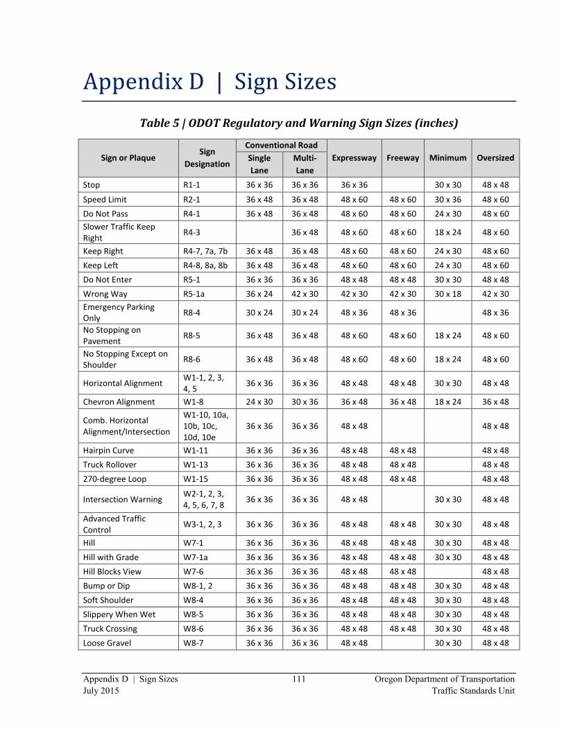
Appendix D | Sign Sizes 111 Oregon Department of Transportation
July 2015 Traffic Standards Unit
Appendix D | Sign Sizes
Table 5 | ODOT Regulatory and Warning Sign Sizes (inches)
Sign or Plaque Sign
Designation
Conventional Road
Expressway Freeway Minimum Oversized Single
Lane
Multi-
Lane
Stop R1-1 36 x 36 36 x 36 36 x 36
30 x 30 48 x 48
Speed Limit R2-1 36 x 48 36 x 48 48 x 60 48 x 60 30 x 36 48 x 60
Do Not Pass R4-1 36 x 48 36 x 48 48 x 60 48 x 60 24 x 30 48 x 60
Slower Traffic Keep Right
R4-3
36 x 48 48 x 60 48 x 60 18 x 24 48 x 60
Keep Right R4-7, 7a, 7b 36 x 48 36 x 48 48 x 60 48 x 60 24 x 30 48 x 60
Keep Left R4-8, 8a, 8b 36 x 48 36 x 48 48 x 60 48 x 60 24 x 30 48 x 60
Do Not Enter R5-1 36 x 36 36 x 36 48 x 48 48 x 48 30 x 30 48 x 48
Wrong Way R5-1a 36 x 24 42 x 30 42 x 30 42 x 30 30 x 18 42 x 30
Emergency Parking Only
R8-4 30 x 24 30 x 24 48 x 36 48 x 36
48 x 36
No Stopping on Pavement
R8-5 36 x 48 36 x 48 48 x 60 48 x 60 18 x 24 48 x 60
No Stopping Except on Shoulder
R8-6 36 x 48 36 x 48 48 x 60 48 x 60 18 x 24 48 x 60
Horizontal Alignment W1-1, 2, 3, 4, 5
36 x 36 36 x 36 48 x 48 48 x 48 30 x 30 48 x 48
Chevron Alignment W1-8 24 x 30 30 x 36 36 x 48 36 x 48 18 x 24 36 x 48
Comb. Horizontal Alignment/Intersection
W1-10, 10a, 10b, 10c, 10d, 10e
36 x 36 36 x 36 48 x 48
48 x 48
Hairpin Curve W1-11 36 x 36 36 x 36 48 x 48 48 x 48
48 x 48
Truck Rollover W1-13 36 x 36 36 x 36 48 x 48 48 x 48
48 x 48
270-degree Loop W1-15 36 x 36 36 x 36 48 x 48 48 x 48
48 x 48
Intersection Warning W2-1, 2, 3, 4, 5, 6, 7, 8
36 x 36 36 x 36 48 x 48
30 x 30 48 x 48
Advanced Traffic Control
W3-1, 2, 3 36 x 36 36 x 36 48 x 48 48 x 48 30 x 30 48 x 48
Hill W7-1 36 x 36 36 x 36 48 x 48 48 x 48 30 x 30 48 x 48
Hill with Grade W7-1a 36 x 36 36 x 36 48 x 48 48 x 48 30 x 30 48 x 48
Hill Blocks View W7-6 36 x 36 36 x 36 48 x 48 48 x 48
48 x 48
Bump or Dip W8-1, 2 36 x 36 36 x 36 48 x 48 48 x 48 30 x 30 48 x 48
Soft Shoulder W8-4 36 x 36 36 x 36 48 x 48 48 x 48 30 x 30 48 x 48
Slippery When Wet W8-5 36 x 36 36 x 36 48 x 48 48 x 48 30 x 30 48 x 48
Truck Crossing W8-6 36 x 36 36 x 36 48 x 48 48 x 48 30 x 30 48 x 48
Loose Gravel W8-7 36 x 36 36 x 36 48 x 48
30 x 30 48 x 48
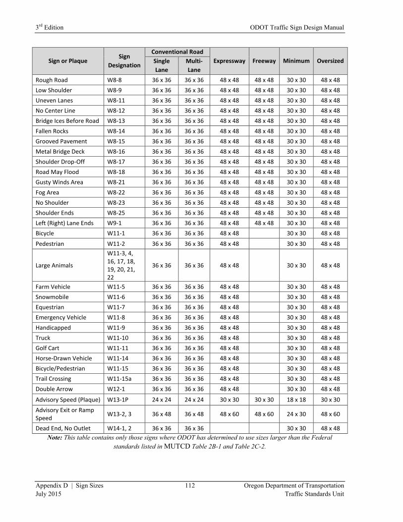
3rd
Edition ODOT Traffic Sign Design Manual
Appendix D | Sign Sizes 112 Oregon Department of Transportation
July 2015 Traffic Standards Unit
Sign or Plaque Sign
Designation
Conventional Road
Expressway Freeway Minimum Oversized Single
Lane
Multi-
Lane
Rough Road W8-8 36 x 36 36 x 36 48 x 48 48 x 48 30 x 30 48 x 48
Low Shoulder W8-9 36 x 36 36 x 36 48 x 48 48 x 48 30 x 30 48 x 48
Uneven Lanes W8-11 36 x 36 36 x 36 48 x 48 48 x 48 30 x 30 48 x 48
No Center Line W8-12 36 x 36 36 x 36 48 x 48 48 x 48 30 x 30 48 x 48
Bridge Ices Before Road W8-13 36 x 36 36 x 36 48 x 48 48 x 48 30 x 30 48 x 48
Fallen Rocks W8-14 36 x 36 36 x 36 48 x 48 48 x 48 30 x 30 48 x 48
Grooved Pavement W8-15 36 x 36 36 x 36 48 x 48 48 x 48 30 x 30 48 x 48
Metal Bridge Deck W8-16 36 x 36 36 x 36 48 x 48 48 x 48 30 x 30 48 x 48
Shoulder Drop-Off W8-17 36 x 36 36 x 36 48 x 48 48 x 48 30 x 30 48 x 48
Road May Flood W8-18 36 x 36 36 x 36 48 x 48 48 x 48 30 x 30 48 x 48
Gusty Winds Area W8-21 36 x 36 36 x 36 48 x 48 48 x 48 30 x 30 48 x 48
Fog Area W8-22 36 x 36 36 x 36 48 x 48 48 x 48 30 x 30 48 x 48
No Shoulder W8-23 36 x 36 36 x 36 48 x 48 48 x 48 30 x 30 48 x 48
Shoulder Ends W8-25 36 x 36 36 x 36 48 x 48 48 x 48 30 x 30 48 x 48
Left (Right) Lane Ends W9-1 36 x 36 36 x 36 48 x 48 48 x 48 30 x 30 48 x 48
Bicycle W11-1 36 x 36 36 x 36 48 x 48
30 x 30 48 x 48
Pedestrian W11-2 36 x 36 36 x 36 48 x 48
30 x 30 48 x 48
Large Animals
W11-3, 4, 16, 17, 18, 19, 20, 21, 22
36 x 36 36 x 36 48 x 48
30 x 30 48 x 48
Farm Vehicle W11-5 36 x 36 36 x 36 48 x 48
30 x 30 48 x 48
Snowmobile W11-6 36 x 36 36 x 36 48 x 48
30 x 30 48 x 48
Equestrian W11-7 36 x 36 36 x 36 48 x 48
30 x 30 48 x 48
Emergency Vehicle W11-8 36 x 36 36 x 36 48 x 48
30 x 30 48 x 48
Handicapped W11-9 36 x 36 36 x 36 48 x 48
30 x 30 48 x 48
Truck W11-10 36 x 36 36 x 36 48 x 48
30 x 30 48 x 48
Golf Cart W11-11 36 x 36 36 x 36 48 x 48
30 x 30 48 x 48
Horse-Drawn Vehicle W11-14 36 x 36 36 x 36 48 x 48
30 x 30 48 x 48
Bicycle/Pedestrian W11-15 36 x 36 36 x 36 48 x 48
30 x 30 48 x 48
Trail Crossing W11-15a 36 x 36 36 x 36 48 x 48
30 x 30 48 x 48
Double Arrow W12-1 36 x 36 36 x 36 48 x 48
30 x 30 48 x 48
Advisory Speed (Plaque) W13-1P 24 x 24 24 x 24 30 x 30 30 x 30 18 x 18 30 x 30
Advisory Exit or Ramp Speed
W13-2, 3 36 x 48 36 x 48 48 x 60 48 x 60 24 x 30 48 x 60
Dead End, No Outlet W14-1, 2 36 x 36 36 x 36
30 x 30 48 x 48
Note: This table contains only those signs where ODOT has determined to use sizes larger than the Federal
standards listed in MUTCD Table 2B-1 and Table 2C-2.
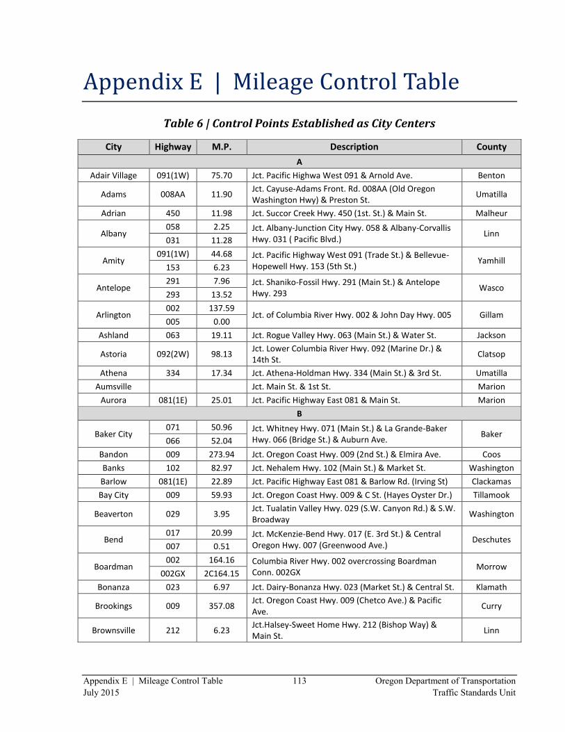
Appendix E | Mileage Control Table 113 Oregon Department of Transportation
July 2015 Traffic Standards Unit
Appendix E | Mileage Control Table
Table 6 | Control Points Established as City Centers
City Highway M.P. Description County
A
Adair Village 091(1W) 75.70 Jct. Pacific Highwa West 091 & Arnold Ave. Benton
Adams 008AA 11.90 Jct. Cayuse-Adams Front. Rd. 008AA (Old Oregon Washington Hwy) & Preston St.
Umatilla
Adrian 450 11.98 Jct. Succor Creek Hwy. 450 (1st. St.) & Main St. Malheur
Albany 058 2.25 Jct. Albany-Junction City Hwy. 058 & Albany-Corvallis
Hwy. 031 ( Pacific Blvd.) Linn
031 11.28
Amity 091(1W) 44.68 Jct. Pacific Highway West 091 (Trade St.) & Bellevue-
Hopewell Hwy. 153 (5th St.) Yamhill
153 6.23
Antelope 291 7.96 Jct. Shaniko-Fossil Hwy. 291 (Main St.) & Antelope
Hwy. 293 Wasco
293 13.52
Arlington 002 137.59
Jct. of Columbia River Hwy. 002 & John Day Hwy. 005 Gillam 005 0.00
Ashland 063 19.11 Jct. Rogue Valley Hwy. 063 (Main St.) & Water St. Jackson
Astoria 092(2W) 98.13 Jct. Lower Columbia River Hwy. 092 (Marine Dr.) & 14th St.
Clatsop
Athena 334 17.34 Jct. Athena-Holdman Hwy. 334 (Main St.) & 3rd St. Umatilla
Aumsville
Jct. Main St. & 1st St. Marion
Aurora 081(1E) 25.01 Jct. Pacific Highway East 081 & Main St. Marion
B
Baker City 071 50.96 Jct. Whitney Hwy. 071 (Main St.) & La Grande-Baker
Hwy. 066 (Bridge St.) & Auburn Ave. Baker
066 52.04
Bandon 009 273.94 Jct. Oregon Coast Hwy. 009 (2nd St.) & Elmira Ave. Coos
Banks 102 82.97 Jct. Nehalem Hwy. 102 (Main St.) & Market St. Washington
Barlow 081(1E) 22.89 Jct. Pacific Highway East 081 & Barlow Rd. (Irving St) Clackamas
Bay City 009 59.93 Jct. Oregon Coast Hwy. 009 & C St. (Hayes Oyster Dr.) Tillamook
Beaverton 029 3.95 Jct. Tualatin Valley Hwy. 029 (S.W. Canyon Rd.) & S.W. Broadway
Washington
Bend 017 20.99 Jct. McKenzie-Bend Hwy. 017 (E. 3rd St.) & Central
Oregon Hwy. 007 (Greenwood Ave.) Deschutes
007 0.51
Boardman 002 164.16 Columbia River Hwy. 002 overcrossing Boardman
Conn. 002GX Morrow
002GX 2C164.15
Bonanza 023 6.97 Jct. Dairy-Bonanza Hwy. 023 (Market St.) & Central St. Klamath
Brookings 009 357.08 Jct. Oregon Coast Hwy. 009 (Chetco Ave.) & Pacific Ave.
Curry
Brownsville 212 6.23 Jct.Halsey-Sweet Home Hwy. 212 (Bishop Way) & Main St.
Linn
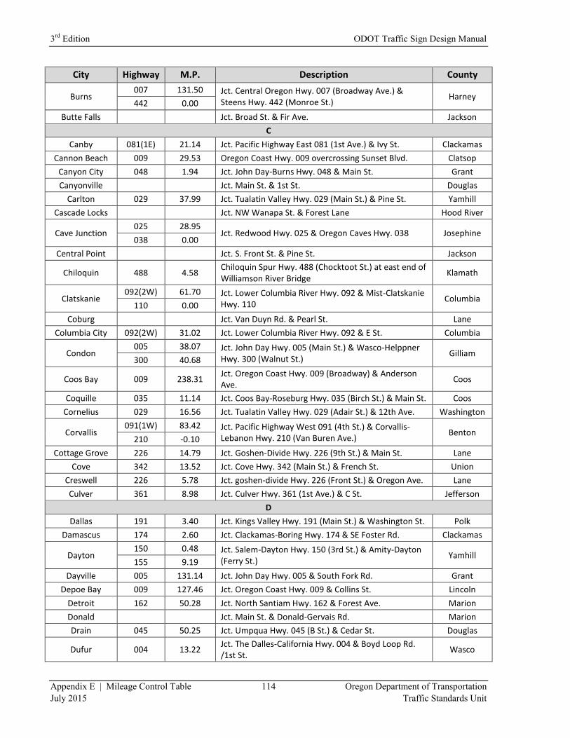
3rd
Edition ODOT Traffic Sign Design Manual
Appendix E | Mileage Control Table 114 Oregon Department of Transportation
July 2015 Traffic Standards Unit
City Highway M.P. Description County
Burns 007 131.50 Jct. Central Oregon Hwy. 007 (Broadway Ave.) &
Steens Hwy. 442 (Monroe St.) Harney
442 0.00
Butte Falls
Jct. Broad St. & Fir Ave. Jackson
C
Canby 081(1E) 21.14 Jct. Pacific Highway East 081 (1st Ave.) & Ivy St. Clackamas
Cannon Beach 009 29.53 Oregon Coast Hwy. 009 overcrossing Sunset Blvd. Clatsop
Canyon City 048 1.94 Jct. John Day-Burns Hwy. 048 & Main St. Grant
Canyonville
Jct. Main St. & 1st St. Douglas
Carlton 029 37.99 Jct. Tualatin Valley Hwy. 029 (Main St.) & Pine St. Yamhill
Cascade Locks
Jct. NW Wanapa St. & Forest Lane Hood River
Cave Junction 025 28.95
Jct. Redwood Hwy. 025 & Oregon Caves Hwy. 038 Josephine 038 0.00
Central Point
Jct. S. Front St. & Pine St. Jackson
Chiloquin 488 4.58 Chiloquin Spur Hwy. 488 (Chocktoot St.) at east end of Williamson River Bridge
Klamath
Clatskanie 092(2W) 61.70 Jct. Lower Columbia River Hwy. 092 & Mist-Clatskanie
Hwy. 110 Columbia
110 0.00
Coburg
Jct. Van Duyn Rd. & Pearl St. Lane
Columbia City 092(2W) 31.02 Jct. Lower Columbia River Hwy. 092 & E St. Columbia
Condon 005 38.07 Jct. John Day Hwy. 005 (Main St.) & Wasco-Helppner
Hwy. 300 (Walnut St.) Gilliam
300 40.68
Coos Bay 009 238.31 Jct. Oregon Coast Hwy. 009 (Broadway) & Anderson Ave.
Coos
Coquille 035 11.14 Jct. Coos Bay-Roseburg Hwy. 035 (Birch St.) & Main St. Coos
Cornelius 029 16.56 Jct. Tualatin Valley Hwy. 029 (Adair St.) & 12th Ave. Washington
Corvallis 091(1W) 83.42 Jct. Pacific Highway West 091 (4th St.) & Corvallis-
Lebanon Hwy. 210 (Van Buren Ave.) Benton
210 -0.10
Cottage Grove 226 14.79 Jct. Goshen-Divide Hwy. 226 (9th St.) & Main St. Lane
Cove 342 13.52 Jct. Cove Hwy. 342 (Main St.) & French St. Union
Creswell 226 5.78 Jct. goshen-divide Hwy. 226 (Front St.) & Oregon Ave. Lane
Culver 361 8.98 Jct. Culver Hwy. 361 (1st Ave.) & C St. Jefferson
D
Dallas 191 3.40 Jct. Kings Valley Hwy. 191 (Main St.) & Washington St. Polk
Damascus 174 2.60 Jct. Clackamas-Boring Hwy. 174 & SE Foster Rd. Clackamas
Dayton 150 0.48 Jct. Salem-Dayton Hwy. 150 (3rd St.) & Amity-Dayton
(Ferry St.) Yamhill
155 9.19
Dayville 005 131.14 Jct. John Day Hwy. 005 & South Fork Rd. Grant
Depoe Bay 009 127.46 Jct. Oregon Coast Hwy. 009 & Collins St. Lincoln
Detroit 162 50.28 Jct. North Santiam Hwy. 162 & Forest Ave. Marion
Donald
Jct. Main St. & Donald-Gervais Rd. Marion
Drain 045 50.25 Jct. Umpqua Hwy. 045 (B St.) & Cedar St. Douglas
Dufur 004 13.22 Jct. The Dalles-California Hwy. 004 & Boyd Loop Rd. /1st St.
Wasco
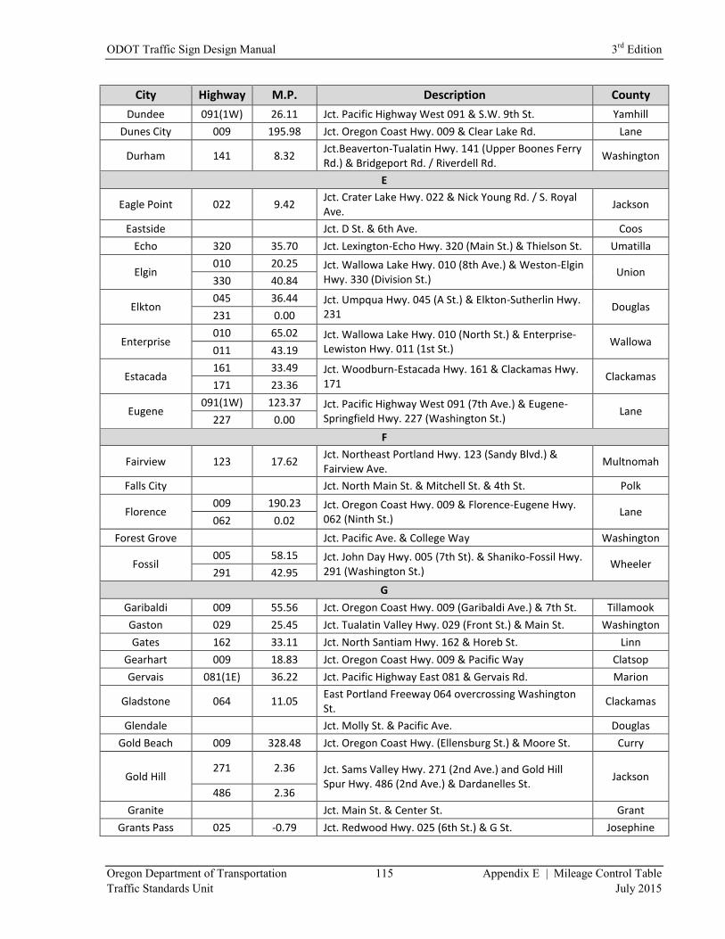
ODOT Traffic Sign Design Manual 3rd
Edition
Oregon Department of Transportation 115 Appendix E | Mileage Control Table
Traffic Standards Unit July 2015
City Highway M.P. Description County
Dundee 091(1W) 26.11 Jct. Pacific Highway West 091 & S.W. 9th St. Yamhill
Dunes City 009 195.98 Jct. Oregon Coast Hwy. 009 & Clear Lake Rd. Lane
Durham 141 8.32 Jct.Beaverton-Tualatin Hwy. 141 (Upper Boones Ferry Rd.) & Bridgeport Rd. / Riverdell Rd.
Washington
E
Eagle Point 022 9.42 Jct. Crater Lake Hwy. 022 & Nick Young Rd. / S. Royal Ave.
Jackson
Eastside
Jct. D St. & 6th Ave. Coos
Echo 320 35.70 Jct. Lexington-Echo Hwy. 320 (Main St.) & Thielson St. Umatilla
Elgin 010 20.25 Jct. Wallowa Lake Hwy. 010 (8th Ave.) & Weston-Elgin
Hwy. 330 (Division St.) Union
330 40.84
Elkton 045 36.44 Jct. Umpqua Hwy. 045 (A St.) & Elkton-Sutherlin Hwy.
231 Douglas
231 0.00
Enterprise 010 65.02 Jct. Wallowa Lake Hwy. 010 (North St.) & Enterprise-
Lewiston Hwy. 011 (1st St.) Wallowa
011 43.19
Estacada 161 33.49 Jct. Woodburn-Estacada Hwy. 161 & Clackamas Hwy.
171 Clackamas
171 23.36
Eugene 091(1W) 123.37 Jct. Pacific Highway West 091 (7th Ave.) & Eugene-
Springfield Hwy. 227 (Washington St.) Lane
227 0.00
F
Fairview 123 17.62 Jct. Northeast Portland Hwy. 123 (Sandy Blvd.) & Fairview Ave.
Multnomah
Falls City
Jct. North Main St. & Mitchell St. & 4th St. Polk
Florence 009 190.23 Jct. Oregon Coast Hwy. 009 & Florence-Eugene Hwy.
062 (Ninth St.) Lane
062 0.02
Forest Grove
Jct. Pacific Ave. & College Way Washington
Fossil 005 58.15 Jct. John Day Hwy. 005 (7th St). & Shaniko-Fossil Hwy.
291 (Washington St.) Wheeler
291 42.95
G
Garibaldi 009 55.56 Jct. Oregon Coast Hwy. 009 (Garibaldi Ave.) & 7th St. Tillamook
Gaston 029 25.45 Jct. Tualatin Valley Hwy. 029 (Front St.) & Main St. Washington
Gates 162 33.11 Jct. North Santiam Hwy. 162 & Horeb St. Linn
Gearhart 009 18.83 Jct. Oregon Coast Hwy. 009 & Pacific Way Clatsop
Gervais 081(1E) 36.22 Jct. Pacific Highway East 081 & Gervais Rd. Marion
Gladstone 064 11.05 East Portland Freeway 064 overcrossing Washington St.
Clackamas
Glendale
Jct. Molly St. & Pacific Ave. Douglas
Gold Beach 009 328.48 Jct. Oregon Coast Hwy. (Ellensburg St.) & Moore St. Curry
Gold Hill 271 2.36 Jct. Sams Valley Hwy. 271 (2nd Ave.) and Gold Hill
Spur Hwy. 486 (2nd Ave.) & Dardanelles St. Jackson
486 2.36
Granite
Jct. Main St. & Center St. Grant
Grants Pass 025 -0.79 Jct. Redwood Hwy. 025 (6th St.) & G St. Josephine
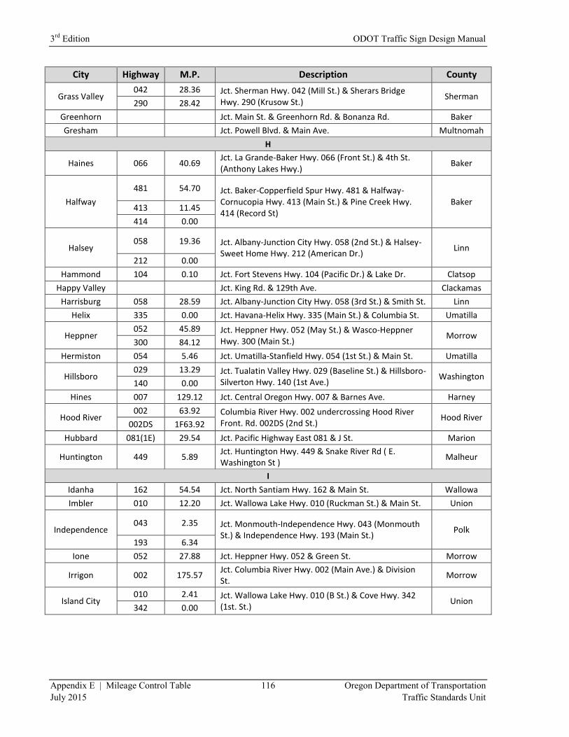
3rd
Edition ODOT Traffic Sign Design Manual
Appendix E | Mileage Control Table 116 Oregon Department of Transportation
July 2015 Traffic Standards Unit
City Highway M.P. Description County
Grass Valley 042 28.36 Jct. Sherman Hwy. 042 (Mill St.) & Sherars Bridge
Hwy. 290 (Krusow St.) Sherman
290 28.42
Greenhorn
Jct. Main St. & Greenhorn Rd. & Bonanza Rd. Baker
Gresham
Jct. Powell Blvd. & Main Ave. Multnomah
H
Haines 066 40.69 Jct. La Grande-Baker Hwy. 066 (Front St.) & 4th St. (Anthony Lakes Hwy.)
Baker
Halfway
481 54.70 Jct. Baker-Copperfield Spur Hwy. 481 & Halfway-Cornucopia Hwy. 413 (Main St.) & Pine Creek Hwy. 414 (Record St)
Baker 413 11.45
414 0.00
Halsey 058 19.36 Jct. Albany-Junction City Hwy. 058 (2nd St.) & Halsey-
Sweet Home Hwy. 212 (American Dr.) Linn
212 0.00
Hammond 104 0.10 Jct. Fort Stevens Hwy. 104 (Pacific Dr.) & Lake Dr. Clatsop
Happy Valley
Jct. King Rd. & 129th Ave. Clackamas
Harrisburg 058 28.59 Jct. Albany-Junction City Hwy. 058 (3rd St.) & Smith St. Linn
Helix 335 0.00 Jct. Havana-Helix Hwy. 335 (Main St.) & Columbia St. Umatilla
Heppner 052 45.89 Jct. Heppner Hwy. 052 (May St.) & Wasco-Heppner
Hwy. 300 (Main St.) Morrow
300 84.12
Hermiston 054 5.46 Jct. Umatilla-Stanfield Hwy. 054 (1st St.) & Main St. Umatilla
Hillsboro 029 13.29 Jct. Tualatin Valley Hwy. 029 (Baseline St.) & Hillsboro-
Silverton Hwy. 140 (1st Ave.) Washington
140 0.00
Hines 007 129.12 Jct. Central Oregon Hwy. 007 & Barnes Ave. Harney
Hood River 002 63.92 Columbia River Hwy. 002 undercrossing Hood River
Front. Rd. 002DS (2nd St.) Hood River
002DS 1F63.92
Hubbard 081(1E) 29.54 Jct. Pacific Highway East 081 & J St. Marion
Huntington 449 5.89 Jct. Huntington Hwy. 449 & Snake River Rd ( E. Washington St )
Malheur
I
Idanha 162 54.54 Jct. North Santiam Hwy. 162 & Main St. Wallowa
Imbler 010 12.20 Jct. Wallowa Lake Hwy. 010 (Ruckman St.) & Main St. Union
Independence 043 2.35 Jct. Monmouth-Independence Hwy. 043 (Monmouth
St.) & Independence Hwy. 193 (Main St.) Polk
193 6.34
Ione 052 27.88 Jct. Heppner Hwy. 052 & Green St. Morrow
Irrigon 002 175.57 Jct. Columbia River Hwy. 002 (Main Ave.) & Division St.
Morrow
Island City 010 2.41 Jct. Wallowa Lake Hwy. 010 (B St.) & Cove Hwy. 342
(1st. St.) Union
342 0.00
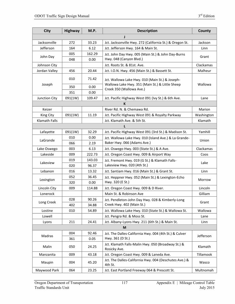
ODOT Traffic Sign Design Manual 3rd
Edition
Oregon Department of Transportation 117 Appendix E | Mileage Control Table
Traffic Standards Unit July 2015
City Highway M.P. Description County
J
Jacksonville 272 33.23 Jct. Jacksonville Hwy. 272 (California St.) & Oregon St. Jackson
Jefferson 164 6.12 Jct. Jefferson Hwy. 164 & Main St. Linn
John Day 005 162.29 Jct. John Day Hwy. 005 (Main St.) & John Day-Burns
Hwy. 048 (Canyon Blvd.) Grant
048 0.00
Johnson City
Jct. Roots St. & 81st. Ave. Clackamas
Jordan Valley 456 20.44 Jct. I.O.N. Hwy. 456 (Main St.) & Bassett St. Malheur
Joseph
010 71.42 Jct. Wallowa Lake Hwy. 010 (Main St.) & Joseph-Wallowa Lake Hwy. 351 (Main St.) & Little Sheep Creek 350 (Wallowa Ave.)
Wallowa 350 0.00
351 0.00
Junction City 091(1W) 109.47 Jct. Pacific Highway West 091 (Ivy St.) & 6th Ave. Lane
K
Keizer
River Rd. N. & Chemawa Rd. Marion
King City 091(1W) 11.19 Jct. Pacific Highway West 091 & Royalty Parkway Washington
Klamath Falls
Jct. Klamath Ave. & 5th St. Klamath
L
Lafayette 091(1W) 32.29 Jct. Pacific Highway West 091 (3rd St.) & Madison St. Yamhill
LaGrande 010 0.00 Jct. Wallowa Lake Hwy. 010 (Island Ave.) & La Grande-
Baker Hwy. 066 (Adams Ave.) Union
066 2.19
Lake Oswego 003 6.13 Jct. Oswego Hwy. 003 (State St.) & A Ave. Clackamas
Lakeside 009 222.73 Jct. Oregon Coast Hwy. 009 & Airport Way Coos
Lakeview 019 143.03 Jct. Fremont Hwy. 019 (G St.) & Klamath Falls-
Lakeview Hwy. 020 (4th St.) Lake
020 96.37
Lebanon 016 13.32 Jct. Santiam Hwy. 016 (Main St.) & Grant St. Linn
Lexington 052 36.45 Jct. Heppner Hwy. 052 (Main St.) & Lexington-Echo
Hwy. 320 (E St.) Morrow
320 0.00
Lincoln City 009 114.88 Jct. Oregon Coast Hwy. 009 & D River. Lincoln
Lonerock
Main St. & Robinson Ave Gilliam
Long Creek 028 90.26 Jct. Pendleton-John Day Hwy. 028 & Kimberly-Long
Creek Hwy. 402 (Main St.) Grant
402 34.88
Lostine 010 54.89 Jct. Wallowa Lake Hwy. 010 (State St.) & Wallowa St. Wallowa
Lowell
Jct. Pengra Rd. & Moss St. Lane
Lyons 211 24.41 Jct. Albany-Lyons Hwy. 211 (6th St.) & Main St. Linn
M
Madras 004 92.46 Jct. The Dalles-California Hwy. 004 (4th St.) & Culver
Hwy. 361 (D St.) Jefferson
361 0.05
Malin 050 24.25 Jct. Klamath Falls-Malin Hwy. 050 (Broadway St.) & Rosicky Ave.
Klamath
Manzanita 009 43.18 Jct. Oregon Coast Hwy. 009 & Laneda Ave. Tillamook
Maupin 004 45.20 Jct. The Dalles-California Hwy. 004 (Deschutes Ave.) & 4th St.
Wasco
Maywood Park 064 23.25 Jct. East Portland Freeway 064 & Prescott St. Multnomah
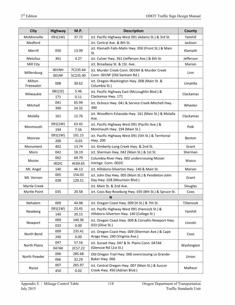
3rd
Edition ODOT Traffic Sign Design Manual
Appendix E | Mileage Control Table 118 Oregon Department of Transportation
July 2015 Traffic Standards Unit
City Highway M.P. Description County
McMinnville 091(1W) 37.72 Jct. Pacific Highway West 091 (Adams St.) & 3rd St. Yamhill
Medford
Jct. Central Ave. & 8th St. Jackson
Merrill 050 13.99 Jct. Klamath Falls-Malin Hwy. 050 (Front St.) & Main St.
Klamath
Metolius 361 4.27 Jct. Culver Hwy. 361 (Jefferson Ave.) & 6th St. Jefferson
Mill City
Jct. Broadway St. & 1St. Ave. Marion
Millersburg 001NH 7C235.64 Jct. Murder Creek Conn. 001NH & Murder Creek
Conn. 001NF (Old Santiam Rd.) Linn
001NF 5C235.90
Milton-Freewater
008 30.62 Jct. Oregon-Washington Hwy. 008 (Main St. & Columbia St.)
Umatilla
Milwaukie 081(1E) 5.46 Jct. Pacific Highway East (McLoughlin Blvd.) &
Clackamas Hwy. 171 Clackamas
171 0.11
Mitchell 041 65.94 Jct. Ochoco Hwy. 041 & Service Creek-Mitchell Hwy.
390 Wheeler
390 24.32
Molalla 161 12.76 Jct. Woodbirn-Estacada Hwy. 161 (Main St.) & Molalla Ave.
Clackamas
Monmouth 091(1W) 63.42 Jct. Pacific Highway West 091 (Pacific Ave.) &
Monmouth Hwy. 194 (Main St.) Polk
194 7.56
Monroe 091(1W) 101.15 Jct. Pacific Highway West 091 (5th St.) & Territorial
Hwy. 200 Benton
200 -0.03
Monument 402 13.74 Jct. Kimberly-Long Creek Hwy. & 2nd St. Grant
Moro 042 18.19 Jct. Sherman Hwy. 042 (Main St.) & 1st St. Sherman
Mosier 002 69.79 Columbia River Hwy. 002 undercrossing Mosier
Intchge. Conn. 002IC Wasco
002IC 4C69.65
Mt. Angel 140 46.13 Jct. Hillsboro-Silverton Hwy. 140 & Main St. Marion
Mt. Vernon 005 154.03 Jct. John Day Hwy. 005 (Main St.) & Pendleton-John
Day Hwy. 028 (Mountain Blvd.) Grant
028 120.51
Myrtle Creek
Jct. Main St. & 2nd Ave. Douglas
Myrtle Point 035 20.58 Jct. Coos Bay-Roseburg Hwy. 035 (8th St.) & Spruce St. Coos
N
Nehalem 009 44.98 Jct. Oregon Coast Hwy. 009 (H St.) & 7th St. Tillamook
Newberg 091(1W) 23.45 Jct. Pacific Highway West 091 (Hancock St.) &
Hillsboro-Silverton Hwy. 140 (College St.) Yamhill
140 20.15
Newport 009 140.36 Jct. Oregon Coast Hwy. 009 & Corvallis-Newport Hwy.
033 (Olive St.) Lincoln
033 0.00
North Bend 009 235.41 Jct. Oregon Coast Hwy. 009 (Sherman Ave.) & Cape
Arago Hwy. 240 (Virginia Ave.) Coos
240 0.00
North Plains 047 57.16 Jct. Sunset Hwy. 047 & N. Plains Conn. 047AK
(Glencoe Rd.\1st St.) Washington
047AK 2C57.22
North Powder 006 285.68 Old Oregon Trail Hwy. 006 overcrossing La Grande-
Baker Hwy. 066 Union
066 32.29
Nyssa 007 265.97 Jct. Central Oregon Hwy. 007 (Main St.) & Succor
Creek Hwy. 450 (Adrian Blvd.) Malheur
450 0.02
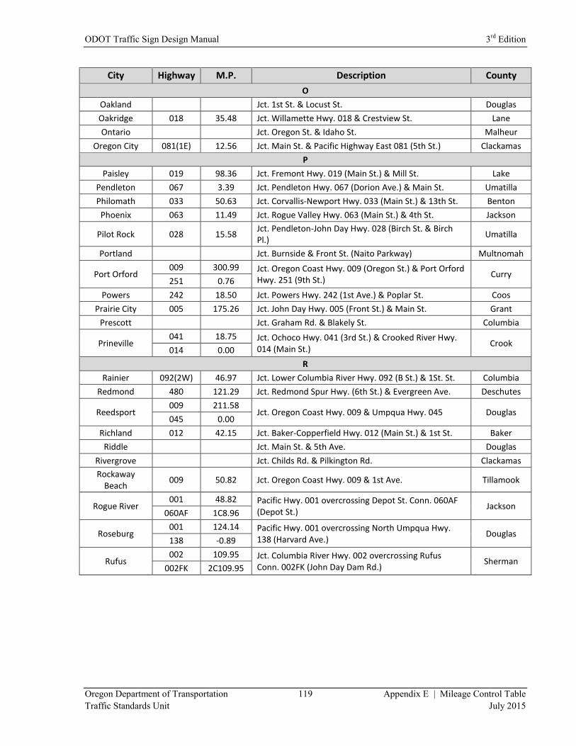
ODOT Traffic Sign Design Manual 3rd
Edition
Oregon Department of Transportation 119 Appendix E | Mileage Control Table
Traffic Standards Unit July 2015
City Highway M.P. Description County
O
Oakland
Jct. 1st St. & Locust St. Douglas
Oakridge 018 35.48 Jct. Willamette Hwy. 018 & Crestview St. Lane
Ontario
Jct. Oregon St. & Idaho St. Malheur
Oregon City 081(1E) 12.56 Jct. Main St. & Pacific Highway East 081 (5th St.) Clackamas
P
Paisley 019 98.36 Jct. Fremont Hwy. 019 (Main St.) & Mill St. Lake
Pendleton 067 3.39 Jct. Pendleton Hwy. 067 (Dorion Ave.) & Main St. Umatilla
Philomath 033 50.63 Jct. Corvallis-Newport Hwy. 033 (Main St.) & 13th St. Benton
Phoenix 063 11.49 Jct. Rogue Valley Hwy. 063 (Main St.) & 4th St. Jackson
Pilot Rock 028 15.58 Jct. Pendleton-John Day Hwy. 028 (Birch St. & Birch Pl.)
Umatilla
Portland
Jct. Burnside & Front St. (Naito Parkway) Multnomah
Port Orford 009 300.99 Jct. Oregon Coast Hwy. 009 (Oregon St.) & Port Orford
Hwy. 251 (9th St.) Curry
251 0.76
Powers 242 18.50 Jct. Powers Hwy. 242 (1st Ave.) & Poplar St. Coos
Prairie City 005 175.26 Jct. John Day Hwy. 005 (Front St.) & Main St. Grant
Prescott
Jct. Graham Rd. & Blakely St. Columbia
Prineville 041 18.75 Jct. Ochoco Hwy. 041 (3rd St.) & Crooked River Hwy.
014 (Main St.) Crook
014 0.00
R
Rainier 092(2W) 46.97 Jct. Lower Columbia River Hwy. 092 (B St.) & 1St. St. Columbia
Redmond 480 121.29 Jct. Redmond Spur Hwy. (6th St.) & Evergreen Ave. Deschutes
Reedsport 009 211.58
Jct. Oregon Coast Hwy. 009 & Umpqua Hwy. 045 Douglas 045 0.00
Richland 012 42.15 Jct. Baker-Copperfield Hwy. 012 (Main St.) & 1st St. Baker
Riddle
Jct. Main St. & 5th Ave. Douglas
Rivergrove
Jct. Childs Rd. & Pilkington Rd. Clackamas
Rockaway Beach
009 50.82 Jct. Oregon Coast Hwy. 009 & 1st Ave. Tillamook
Rogue River 001 48.82 Pacific Hwy. 001 overcrossing Depot St. Conn. 060AF
(Depot St.) Jackson
060AF 1C8.96
Roseburg 001 124.14 Pacific Hwy. 001 overcrossing North Umpqua Hwy.
138 (Harvard Ave.) Douglas
138 -0.89
Rufus 002 109.95 Jct. Columbia River Hwy. 002 overcrossing Rufus
Conn. 002FK (John Day Dam Rd.) Sherman
002FK 2C109.95
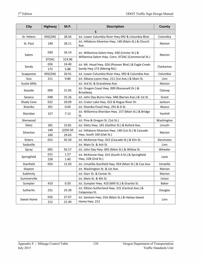
3rd
Edition ODOT Traffic Sign Design Manual
Appendix E | Mileage Control Table 120 Oregon Department of Transportation
July 2015 Traffic Standards Unit
City Highway M.P. Description County
S
St. Helens 092(2W) 28.56 Jct. Lower Columbia River Hwy 092 & Columbia Blvd. Columbia
St. Paul 140 28.11 Jct. Hillsboro-Silverton Hwy. 140 (Main St.) & Church Ave.
Marion
Salem 030 26.14 Jct. Willamina-Salem Hwy. 030 (Center St.) &
Willamina-Salem Hwy. Conn. 072AC (Commercial St.) Marion
072AC 1C4.96
Sandy 026 24.40 Jct. Mt. Hood Hwy. 026 (Pioneer Blvd.) & Eagle Creek-
Sandy Hwy 172 (Meinig Rd.) Clackamas
172 5.88
Scappoose 092(2W) 20.91 Jct. Lower Columbia River Hwy. 092 & Columbia Ave. Columbia
Scio 211 9.80 Jct. Albany-Lyons Hwy. 211 (1st Ave.) & Main St. Linn
Scotts Mills
Jct. 3rd St. & Grandview Ave. Marion
Seaside 009 21.05 Jct. Oregon Coast Hwy. 009 (Roosevelt Dr.) & Broadway
Clatsop
Seneca 048 25.26 Jct. John Day-Burns Hwy. 048 (Barnes Ave.) & 1st St. Grant
Shady Cove 022 20.09 Jct. Crater Lake Hwy. 022 & Rogue River Dr. Jackson
Shaniko 291 0.04 Jct. Shaniko-Fossil Hwy. 291 & D St. Wasco
Sheridan 157 7.13 Jct. Willamina-Sheridan Hwy. 157 (Main St.) & Bridge St.
Yamhill
Sherwood
Jct. Pine & Oregon St. (1st St.) Washington
Siletz 181 23.81 Jct. Siletz Hwy. 181 (Gaither St.) & Buford Ave. Lincoln
Silverton 140 (2)50.50 Jct. Hillsboro-Silverton Hwy. 140 (1st St.) & Cascade
Hwy. South 160 (Oak St.) Marion
160 29.65
Sisters 015 92.50 Jct. McKenzie Hwy. 015 (Cascade St.) & Elm St. Deschutes
Sodaville
Jct. Main St. & Ash St. Linn
Spray 005 92.57 Jct. John Day Hwy. 005 (Main St.) & Willow St. Wheeler
Springfield 015 1.57 Jct. McKenzie Hwy. 015 (South A St.) & Springfield
Hwy. 228 (2nd St.) Lane
228 1.40
Stanfield 054 11.03 Jct. Umatilla-Stanfield Hwy. 054 (Main St.) & Coe Ave. Umatilla
Stayton
Jct. Washington St. & 1st Ave. Marion
Sublimity
Jct. Starr St. & Center St. Marion
Summerville
Jct. Main St. & 4th St. Union
Sumpter 410 0.50 Jct. Sumpter Hwy. 410 (Mill St.) & Granite St. Baker
Sutherlin 231 25.39 Jct. Elkton-Sutherland Hwy. 231 (Central Ave.) & Calapooya St.
Douglas
Sweet Home 016 27.07 Jct. Santiam Hwy. 016 (Main St.) & Halsey-Sweet
Home Hwy. 212 Linn
212 21.40

ODOT Traffic Sign Design Manual 3rd
Edition
Oregon Department of Transportation 121 Appendix E | Mileage Control Table
Traffic Standards Unit July 2015
City Highway M.P. Description County
T
Talent 063 14.20 Jct. Rogue Valley Hwy. 063 & W. Valleyview Rd. Jackson
Tangent 058 8.81 Jct. Albany-Junction City Hwy. 058 & Birdfoot Dr. Linn
The Dalles
Jct. 3rd St. & Union St. Wasco
Tigard 091(1W) 8.65 Jct. Pacific Hwy. West 091 & Beaverton-Tigard Hwy.
144 Washington
144 5.90
Tillamook
009 65.74 Jct. Oregon Coast Hwy. 009 (Main Ave.) & Wilson River Hwy. 037 (3rd St.) & Netarts Hwy. 131 (3rd St.)
Tillamook 037 0.00
131 9.08
Timberline 173 0.12 Beg. Of Timberline Hwy. 173 Clackamas
Toledo
Jct. Main St. & 3rd St. Lincoln
Troutdale
Jct. Historic Columbia River Hwy. (Columbia Blvd). & SW 257th. Ave (NW Graham Rd)
Multnomah
Tualatin 001 289.50 Jct. Pacific Hwy. 001 undercrossing Nyberg Rd. Washington
Turner
Jct. 3rd St. & Chicago St. Marion
U
Ukiah 341 1.24 Jct. Main St. & Camas St. Umatilla
Umatilla 002 182.96 Jct. 6th St. & G St. Umatilla
Union 066 16.51 Jct. La Grande-Baker Hwy. 066 (Main St.) & Beakman
St. Union
340 0.00
Unity 005 212.45 Jct. John Day Hwy. 005 (Main St./1st Ave.) & South Burnt River Ln. (S. Fork Rd.)
Baker
V
Vale 005 278.21 Jct. John Day Hwy. 005 (Glenn St.) & Central Oregon
Hwy. (A St.) Malheur
007 246.39
Veneta 062 46.92 Jct. Florence-Eugene Hwy. 062 and Territorial Hwy.
200 Lane
200 19.49
Vernonia 102 62.09 Jct. Nehalem Hwy. 102 (Bridge St.) & State Ave. Columbia
W
Waldport 009 155.90 Jct. Oregon Coast Hwy. 009 & Alsea Hwy. 027
(Hemlock St.) Lincoln
027 0.00
Wallowa 010 47.31 Jct. Wallowa Lake Hwy. 010 (1st St.) & Ellen St. & Whiskey Creek Rd.
Wallowa
Warrenton 104 3.32 Jct. Ft. Stevens Hwy. 104 (Main Ave.) & Warrenton-
Astoria Hwy. 105 (Harbor St.) Clatsop
105 0.00
Wasco 300 -0.09 Jct. Wasco-Heppner Hwy. 300 (Clark St.) & Celio-
Wasco Hwy. 301 (1st. St.) Sherman
301 15.57
Waterloo
Jct. Gross St. & 4th St. Linn
West Linn 064 8.82 E. Portland Freeway Hwy 064 overcrossing Oswego
Hwy. 003 (Willamette Dr.) Clackamas
003 11.17
Weston
Jct. Water St. & Main St. Umatilla
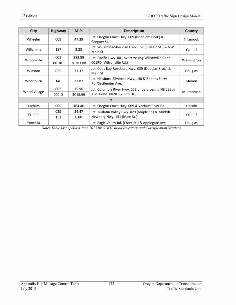
3rd
Edition ODOT Traffic Sign Design Manual
Appendix E | Mileage Control Table 122 Oregon Department of Transportation
July 2015 Traffic Standards Unit
City Highway M.P. Description County
Wheeler 009 47.39 Jct. Oregon Coast Hwy. 009 (Nehalem Blvd.) & Gregory St.
Tillamook
Willamina 157 2.28 Jct. Willamina-Sheridan Hwy. 157 (S. Main St.) & NW Main St.
Yamhill
Wilsonville 001 283.88 Jct. Pacific Hwy. 001 overcrossing Wilsonville Conn.
001RD (Wilsonville Rd.) Washington
001RD 2C283.88
Winston 035 73.37 Jct. Coos Bay-Roseburg Hwy. 035 (Douglas Blvd.) & Main St.
Douglas
Woodburn 140 37.87 Jct. Hillsboro-Silverton Hwy. 140 & Boones Ferry Rd./Settlemier Ave.
Marion
Wood Village 002 15.96 Jct. Columbia River Hwy. 002 undercrossing NE 238th
Ave. Conn. 002IO (238th Dr.) Multnomah
002IO 5C15.99
Y
Yachats 009 164.46 Jct. Oregon Coast Hwy. 009 & Yachats River Rd. Lincoln
Yamhill 029 34.47 Jct. Tualatin Valley Hwy. 029 (Maple St.) & Yamhill-
Newberg Hwy. 151 (Main St.) Yamhill
151 0.00
Yoncalla
Jct. Eagle Valley Rd. (Front St.) & Applegate Ave. Douglas
Note: Table last updated June 2015 by ODOT Road Inventory and Classification Services
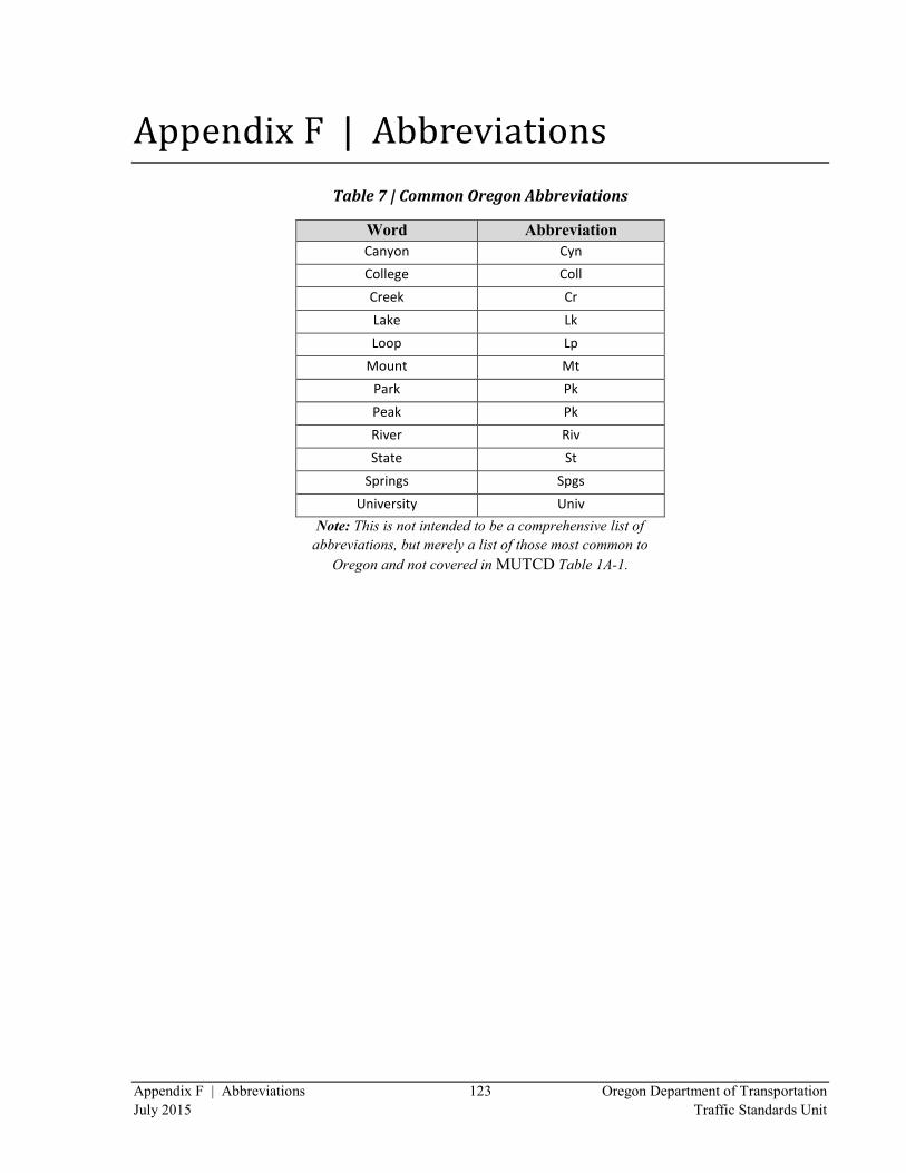
Appendix F | Abbreviations 123 Oregon Department of Transportation
July 2015 Traffic Standards Unit
Appendix F | Abbreviations
Table 7 | Common Oregon Abbreviations
Word Abbreviation
Canyon Cyn
College Coll
Creek Cr
Lake Lk
Loop Lp
Mount Mt
Park Pk
Peak Pk
River Riv
State St
Springs Spgs
University Univ
Note: This is not intended to be a comprehensive list of
abbreviations, but merely a list of those most common to
Oregon and not covered in MUTCD Table 1A-1.