opc-term-uk - farnell element14 · mid-span method insulation shield cable insulation shield cable...
TRANSCRIPT
5.4
362
Introduction
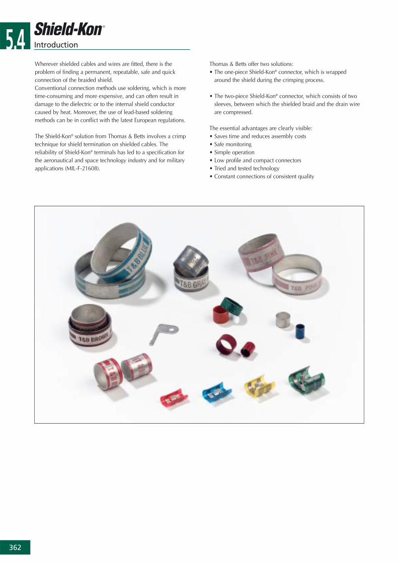
Wherever shielded cables and wires are fitted, there is theproblem of finding a permanent, repeatable, safe and quickconnection of the braided shield.Conventional connection methods use soldering, which is moretime-consuming and more expensive, and can often result indamage to the dielectric or to the internal shield conductorcaused by heat. Moreover, the use of lead-based solderingmethods can be in conflict with the latest European regulations.
The Shield-Kon® solution from Thomas & Betts involves a crimptechnique for shield termination on shielded cables. Thereliability of Shield-Kon® terminals has led to a specification forthe aeronautical and space technology industry and for militaryapplications (MIL-F-21608).
Thomas & Betts offer two solutions:• The one-piece Shield-Kon® connector, which is wrapped
around the shield during the crimping process.
• The two-piece Shield-Kon® connector, which consists of twosleeves, between which the shielded braid and the drain wireare compressed.
The essential advantages are clearly visible:• Saves time and reduces assembly costs • Safe monitoring• Simple operation• Low profile and compact connectors• Tried and tested technology• Constant connections of consistent quality
5.4
363
Technical Information: One-piece Shield-Kon® connectors
Material Copper, conform to CDA No. 110Plating Tin, electro-plated (thickness 3 to 8 µm),
in accordance with MIL-T-10727AInsulation Polyester film (Mylar® type),
colour coded for size identificationTemperature -65°C to +125°C
Mylar® is a registered trade mark of Du Pont de Nemours
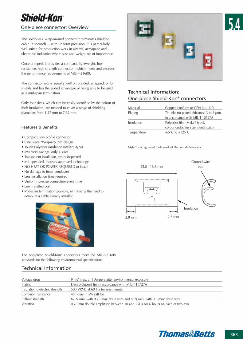
One-piece connector: Overview
This solderless, wrap-around connector terminates shieldedcable in seconds ... with uniform precision. It is particularlywell suited for production work in aircraft, aerospace andelectronic industries where size and weight are of importance.
Once crimped, it provides a compact, lightweight, lowresistance, high strength connection, which meets and exceedsthe performance requirements of MIL-F-21608.
The connector works equally well on braided, wrapped, or foilshields and has the added advantage of being able to be usedas a mid-span termination.
Only four sizes, which can be easily identified by the colour oftheir insulation, are needed to cover a range of shieldingdiameters from 1.27 mm to 7.62 mm.
Features & Benefits
• Compact, low profile connector • One piece “Wrap-around” design• Tough Polyester insulation (Mylar® -type) • Inventory savings: only 4 sizes• Transparent insulation, easily inspected• MIL specified, industry approved technology• NO HEAT OR POWER REQUIRED to install• No damage to inner conductor• Less installation time required• Uniform, precise connection every time• Low installed cost• Mid-span termination possible, eliminating the need to
demount a cable already installed
The one-piece Shield-Kon® connectors meet the MIL-F-21608standards for the following environmental specifications:
Voltage drop 9 mV max. at 1 Ampere after environmental exposurePlating Electro-deposit tin in accordance with MIL-T-10727AInsulation dielectric strength 500 VRMS at 60 Hz for one minuteCorrosion resistance 48 hours in 5% salt fogPullout strength 67 N min. with 0.25 mm2 drain wire and 85N min. with 0.5 mm2 drain wireVibration 0.76 mm double amplitude between 10 and 55Hz for 6 hours on each of two axis
Technical Information
15.0 - 16.3 mm
2.8 mm 2.8 mm
Ground wiretrap
Insulation
5.4
364
5.3One-piece connector: Connectors
Ordering Information: one-piece Shield-Kon® connectors
PRODUCT REF. COLOUR SHIELD DIAMETER ACCEPTABLE DRAIN QUANTITY INSTALLATION
RANGE WIRE SIZE** TOOL*
[mm] [pieces]
RSK101 1000
red 1.27 - 2.28 1 or 2 pieces 0.25mm2
RSK5101 100
RSK201 1000
blue 2.29 - 3.65 1 or 2 pieces 0.25mm2, WT740
RSK5201 or 1 piece 0.5mm2
100 ERG740
RSK301 1000 13300-TB
yellow 3.66 - 5.12 1 or 2 pieces 0.25mm2,
RSK5301 or 1 piece 0.5mm2
100
RSK401 1000
green 5.13 - 7.62 1 or 2 pieces 0.5mm2,
RSK5401 or 1 piece 0.75mm2
100
(*) See pages 369 to 372 for tooling specifications and for die selection(**) Alternatively, a special accessory (RSK-flag) can be used in place of the drain wire, with the yellow and the green connectors (see below)
Note: the connectors can also be supplied on reel for high volume applications with semi-automatic machine (see page 372)
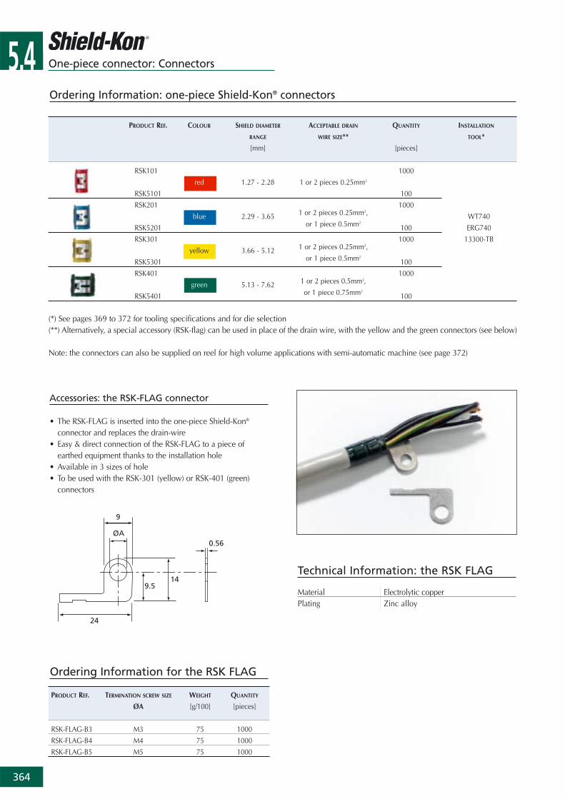
Accessories: the RSK-FLAG connector
• The RSK-FLAG is inserted into the one-piece Shield-Kon®
connector and replaces the drain-wire• Easy & direct connection of the RSK-FLAG to a piece of
earthed equipment thanks to the installation hole• Available in 3 sizes of hole • To be used with the RSK-301 (yellow) or RSK-401 (green)
connectors
Ordering Information for the RSK FLAG
PRODUCT REF. TERMINATION SCREW SIZE WEIGHT QUANTITY
ØA [g/100] [pieces]
RSK-FLAG-B3 M3 75 1000
RSK-FLAG-B4 M4 75 1000
RSK-FLAG-B5 M5 75 1000
Technical Information: the RSK FLAG
Material Electrolytic copperPlating Zinc alloy
5.4
365
5.3 One-piece connector: Installation methods and procedure
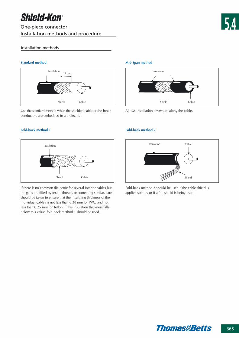
Mid-Span method
Insulation
Shield Cable
Insulation
Shield Cable
11 mm
Insulation
Shield Cable
Insulation
Shield
Cable
Standard method
Fold-back method 1 Fold-back method 2
Allows installation anywhere along the cable. Use the standard method when the shielded cable or the innerconductors are embedded in a dielectric.
If there is no common dielectric for several interior cables butthe gaps are filled by textile threads or something similar, careshould be taken to ensure that the insulating thickness of theindividual cables is not less than 0.38 mm for PVC, and notless than 0.25 mm for Teflon. If this insulation thickness fallsbelow this value, fold-back method 1 should be used.
Fold-back method 2 should be used if the cable shield isapplied spirally or if a foil shield is being used.
Installation methods
5.4
366
One-piece connector: Installation methods and procedure
Installation procedures
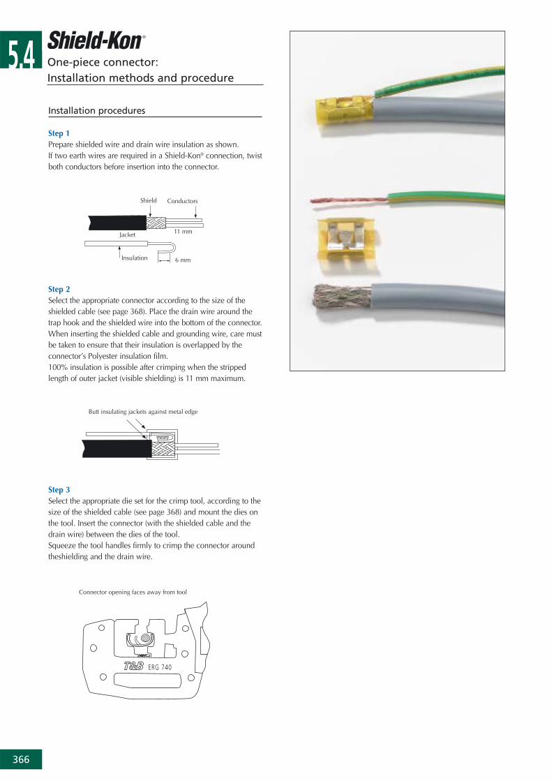
Step 1Prepare shielded wire and drain wire insulation as shown. If two earth wires are required in a Shield-Kon® connection, twistboth conductors before insertion into the connector.
Step 2Select the appropriate connector according to the size of theshielded cable (see page 368). Place the drain wire around thetrap hook and the shielded wire into the bottom of the connector. When inserting the shielded cable and grounding wire, care mustbe taken to ensure that their insulation is overlapped by theconnector’s Polyester insulation film.100% insulation is possible after crimping when the strippedlength of outer jacket (visible shielding) is 11 mm maximum.
Step 3Select the appropriate die set for the crimp tool, according to thesize of the shielded cable (see page 368) and mount the dies onthe tool. Insert the connector (with the shielded cable and thedrain wire) between the dies of the tool.Squeeze the tool handles firmly to crimp the connector aroundtheshielding and the drain wire.
Shield Conductors
Jacket 11 mm
Insulation 6 mm
Butt insulating jackets against metal edge
Connector opening faces away from tool

5.4
367
One-piece connector kits
Product Ref.: RSK-SET-IT
Same as Product Ref. RSK-SET, but with a smaller range ofplastic dies.
The case (Product Ref. RSK-SET-IT) contains:• 1 ergonomic hand tool (Product Ref. ERG-740)• 1 gauge (Product Ref. RSK-LEHRE) for instant selection of the
die and the connector to be used• 1 bench-mount stand• 4 plastic dies (Product Ref. 101A, 201D, 301G, 401K)• 100 pieces of RSK101 (red) connectors• 100 pieces of RSK201 (blue) connectors• 100 pieces of RSK301 (yellow) connectors• 100 pieces of RSK401 (green) connectors
Dimensions of plastic case (L x W x H): 320 x 260 x 75 mmWeight of plastic case with content: 2 kg
Product Ref.: RSK-SET
The Shield-Kon® connection system is now available as acomprehensive kit in a robust thermoplastic case which provides allyou need to be efficient in the field without any additional tooling.
The case (Product Ref. RSK-SET) contains:• 1 ergonomic hand tool (Product Ref. ERG-740)• 1 gauge (Product Ref.) RSK-LEHRE for instant selection of the die
and the connector to be used• All the 13 plastic dies (Product Ref. 101A to 401M, see page 370)
to cover a wide range of shielded cable diameters• 100 pieces of RSK101 (red) connectors• 100 pieces of RSK201 (blue) connectors• 100 pieces of RSK301 (yellow) connectors• 100 pieces of RSK401 (green) connectors
Dimensions of plastic case (L x W x H): 320 x 260 x 75 mmWeight of plastic case with content: 2.2 kg
5.4
368
PRODUCT REF. COLOUR SHIELD DIAMETER PLASTIC DIES METAL DIES ACCEPTABLE DRAIN
FOR 13300-TB FOR ERG-740 WIRE SIZE
[mm] WT-740 AND ERG-740
1.27-1.79 101A D-101ARSK 101 red1.80-2.28 101B D-101B
1 or 2 pieces 0.25mm2
2.29-2.55 201C D-201C
2.56-3.00 201D D-201DRSK 201 blue
3.01-3.34 201E D-201E1 or 2 pieces 0.25mm2 or 1 piece 0.5mm2
3.35-3.65 201F D-201F
3.66-4.13 301G D-301G
RSK 301 yellow 4.14-4.71 301H D-301H 1 or 2 pieces 0.25mm2 or 1 piece 0.5mm2
4.72-5.12 301J D-301J
5.13-5.86 401K D-401K
5.87-6.36 401L D-401LRSK 401 green
6.37-7.00 401M D-401M1 or 2 pieces 0.5mm2 or 1 piece 0.75mm2
7.01-7.62 401N D-401N
One-piece Shield-Kon® connectors & die selection table
One-piece connector:Connector and die selection
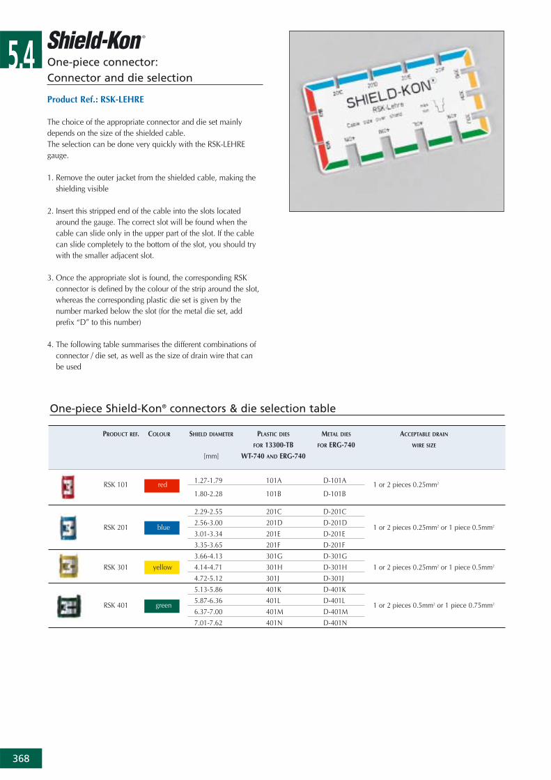
Product Ref.: RSK-LEHRE
The choice of the appropriate connector and die set mainlydepends on the size of the shielded cable. The selection can be done very quickly with the RSK-LEHREgauge.
1. Remove the outer jacket from the shielded cable, making theshielding visible
2. Insert this stripped end of the cable into the slots locatedaround the gauge. The correct slot will be found when thecable can slide only in the upper part of the slot. If the cablecan slide completely to the bottom of the slot, you should trywith the smaller adjacent slot.
3. Once the appropriate slot is found, the corresponding RSKconnector is defined by the colour of the strip around the slot,whereas the corresponding plastic die set is given by thenumber marked below the slot (for the metal die set, addprefix “D” to this number)
4. The following table summarises the different combinations ofconnector / die set, as well as the size of drain wire that canbe used

5.4
369
Standard hand tool
Product Ref.: WT740
• Standard hand tool• MIL specified• Robust construction: metallic frame, partially covered with
plastic • Can be used only with plastic dies (see page 370) • All the dies are easily interchangeable• Parallel action crimp• Shure-Stake™ mechanism: once pressing has commenced,
the tool can be re-opened only after successful completionof the crimping cycle
• Supplied in a wood box containing 1 tool (dies to be orderedseparately)
Ergonomic hand tools
Product Ref.: ERG-740
• Ergonomic hand tool• Robust construction: metallic frame, partially covered with
plastic • Can be used either with plastic dies (see page 370) for
small volume or with metal dies (see page 371) for mediumto high volume applications
• All the dies are easily interchangeable (to be orderedseparately)
• Parallel action crimp• Shure-Stake™ mechanism: once pressing has commenced,
the tool can be re-opened only after successful completionof the crimping cycle
• Supplied in a plastic case with:- 1 tool- 1 bench-mount stand for easier use in volume production- 1 gauge (Product Ref. RSK-LEHRE) for instant selection of
the die and the connector to be used
Product Ref.: ERG740-01
Same as ERG-740, but supplied in a plastic case with:- 1 tool- 1 bench-mount stand for easier use in mass production- 1 RSK-LEHRE gauge for instant selection of the die and the
connector to be used- 1 metal die D-101A- 1 metal die D-201C- 1 metal die D-301J- 1 metal die D-401M
One-piece connector: Tooling
Dimensions of tool (L x W x H): 254 x 97 x 12 mmWeight of tool: 795 g
Dimensions of tool (L x W x H): 210 x 155 x 25 mm Weight of tool: 470 gDimensions of plastic case (L x W x H): 245 x 210 x 55 mmWeight of plastic case with content: 930 g
Dimensions of plastic case (L x W x H): 245 x 210 x 55 mmWeight of plastic case with content: 1200 g
5.4
370
Technical Information
Operating pressure 4.1 - 5.5 bar (60-80 psi) with a maximum of 8.3 bar (120 psi)
Output force 5360 N at 120 psiPiston stroke 1.3 cm minimumFinish Anodise Weight 1.4kgAir hose length 2.44 mAir hose coupling Hansen “13”
One-piece connector: Tooling
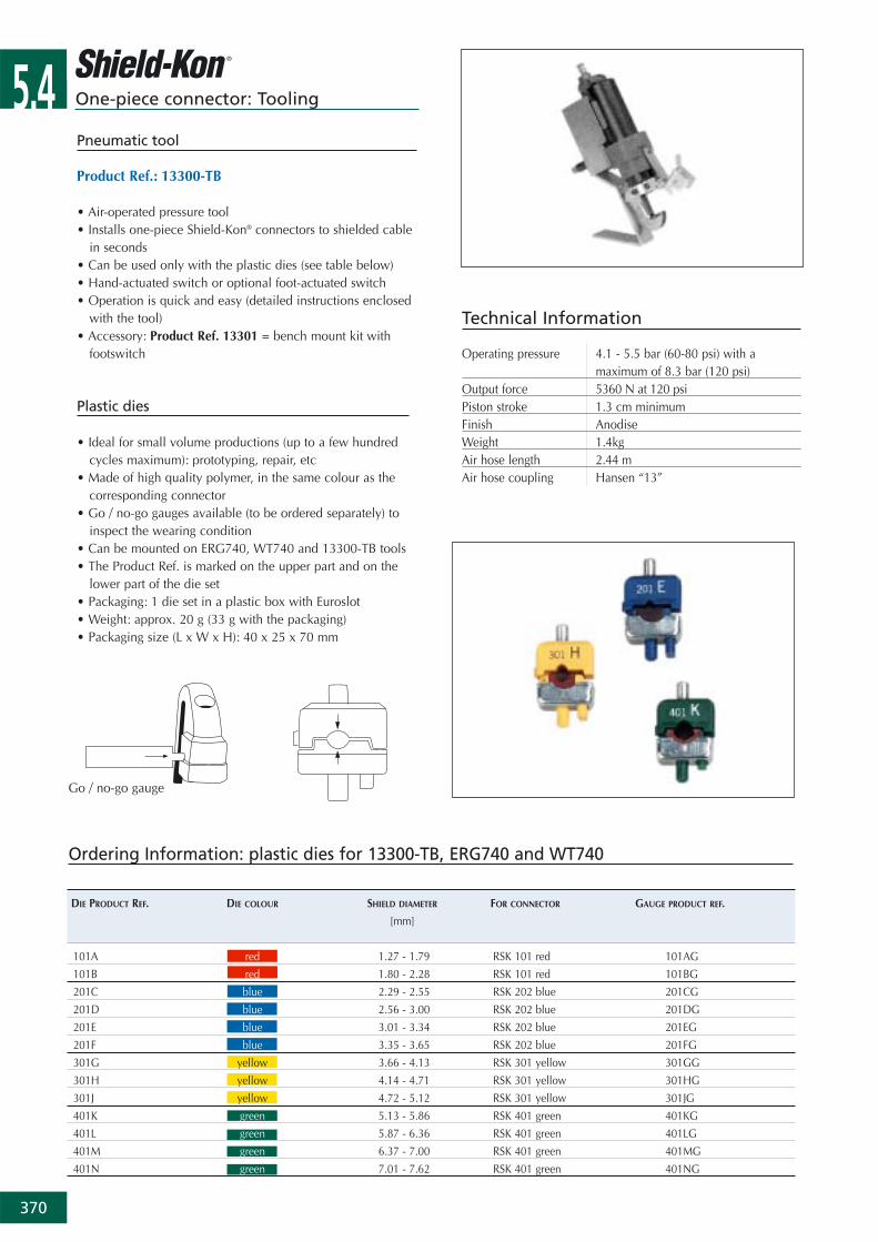
Pneumatic tool
Product Ref.: 13300-TB
• Air-operated pressure tool • Installs one-piece Shield-Kon® connectors to shielded cable
in seconds • Can be used only with the plastic dies (see table below)• Hand-actuated switch or optional foot-actuated switch• Operation is quick and easy (detailed instructions enclosed
with the tool)• Accessory: Product Ref. 13301 = bench mount kit with
footswitch
Plastic dies
• Ideal for small volume productions (up to a few hundredcycles maximum): prototyping, repair, etc
• Made of high quality polymer, in the same colour as thecorresponding connector
• Go / no-go gauges available (to be ordered separately) toinspect the wearing condition
• Can be mounted on ERG740, WT740 and 13300-TB tools• The Product Ref. is marked on the upper part and on the
lower part of the die set• Packaging: 1 die set in a plastic box with Euroslot• Weight: approx. 20 g (33 g with the packaging)• Packaging size (L x W x H): 40 x 25 x 70 mm
Ordering Information: plastic dies for 13300-TB, ERG740 and WT740
DIE PRODUCT REF. DIE COLOUR SHIELD DIAMETER FOR CONNECTOR GAUGE PRODUCT REF.
[mm]
101A red 1.27 - 1.79 RSK 101 red 101AG
101B red 1.80 - 2.28 RSK 101 red 101BG
201C blue 2.29 - 2.55 RSK 202 blue 201CG
201D blue 2.56 - 3.00 RSK 202 blue 201DG
201E blue 3.01 - 3.34 RSK 202 blue 201EG
201F blue 3.35 - 3.65 RSK 202 blue 201FG
301G yellow 3.66 - 4.13 RSK 301 yellow 301GG
301H yellow 4.14 - 4.71 RSK 301 yellow 301HG
301J yellow 4.72 - 5.12 RSK 301 yellow 301JG
401K green 5.13 - 5.86 RSK 401 green 401KG
401L green 5.87 - 6.36 RSK 401 green 401LG
401M green 6.37 - 7.00 RSK 401 green 401MG
401N green 7.01 - 7.62 RSK 401 green 401NG
Go / no-go gauge
5.4
371
One-piece connector: Tooling
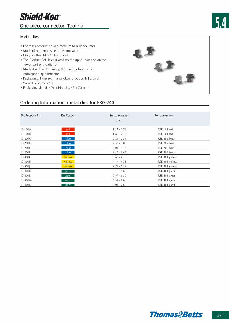
Metal dies
• For mass production and medium to high volumes • Made of hardened steel, does not wear • Only for the ERG740 hand tool• The Product Ref. is engraved on the upper part and on the
lower part of the die set• Marked with a dot having the same colour as the
corresponding connector• Packaging: 1 die set in a cardboard box with Euroslot• Weight: approx. 75 g • Packaging size (L x W x H): 45 x 45 x 70 mm
Ordering Information: metal dies for ERG-740
DIE PRODUCT REF. DIE COLOUR SHIELD DIAMETER FOR CONNECTOR
[mm]
D-101A red 1.27 - 1.79 RSK 101 red
D-101B red 1.80 - 2.28 RSK 101 red
D-201C blue 2.29 - 2.55 RSK 202 blue
D-201D blue 2.56 - 3.00 RSK 202 blue
D-201E blue 3.01 - 3.34 RSK 202 blue
D-201F blue 3.35 - 3.65 RSK 202 blue
D-301G yellow 3.66 - 4.13 RSK 301 yellow
D-301H yellow 4.14 - 4.71 RSK 301 yellow
D-301J yellow 4.72 - 5.12 RSK 301 yellow
D-401K green 5.13 - 5.86 RSK 401 green
D-401L green 5.87 - 6.36 RSK 401 green
D-401M green 6.37 - 7.00 RSK 401 green
D-401N green 7.01 - 7.62 RSK 401 green
5.4
372
PRODUCT REF. COLOUR REEL SHIELD TOOL DIE DRAIN WIRE
QUANTITY DIAMETER DIES ADAPTOR (BRAID)
[pieces] [mm]
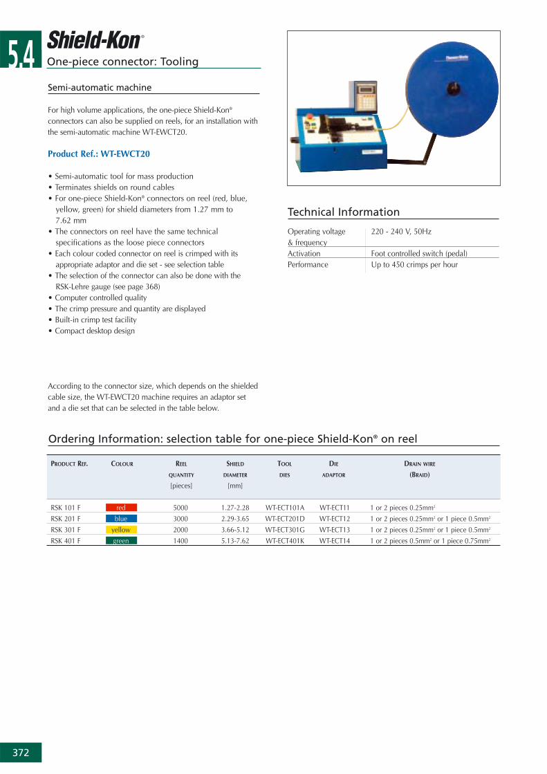
RSK 101 F red 5000 1.27-2.28 WT-ECT101A WT-ECT11 1 or 2 pieces 0.25mm2
RSK 201 F blue 3000 2.29-3.65 WT-ECT201D WT-ECT12 1 or 2 pieces 0.25mm2 or 1 piece 0.5mm2
RSK 301 F yellow 2000 3.66-5.12 WT-ECT301G WT-ECT13 1 or 2 pieces 0.25mm2 or 1 piece 0.5mm2
RSK 401 F green 1400 5.13-7.62 WT-ECT401K WT-ECT14 1 or 2 pieces 0.5mm2 or 1 piece 0.75mm2
Ordering Information: selection table for one-piece Shield-Kon® on reel
One-piece connector: Tooling
According to the connector size, which depends on the shieldedcable size, the WT-EWCT20 machine requires an adaptor setand a die set that can be selected in the table below.
Semi-automatic machine
For high volume applications, the one-piece Shield-Kon®
connectors can also be supplied on reels, for an installation withthe semi-automatic machine WT-EWCT20.
Product Ref.: WT-EWCT20
• Semi-automatic tool for mass production• Terminates shields on round cables• For one-piece Shield-Kon® connectors on reel (red, blue,
yellow, green) for shield diameters from 1.27 mm to 7.62 mm
• The connectors on reel have the same technicalspecifications as the loose piece connectors
• Each colour coded connector on reel is crimped with itsappropriate adaptor and die set - see selection table
• The selection of the connector can also be done with the RSK-Lehre gauge (see page 368)
• Computer controlled quality• The crimp pressure and quantity are displayed• Built-in crimp test facility• Compact desktop design
Technical Information
Operating voltage 220 - 240 V, 50Hz& frequency Activation Foot controlled switch (pedal)Performance Up to 450 crimps per hour
5.4
373
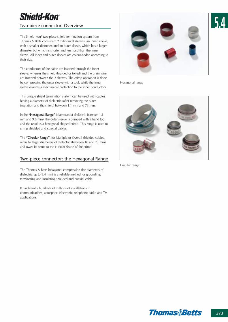
Two-piece connector: Overview
The Shield-Kon® two-piece shield termination system fromThomas & Betts consists of 2 cylindrical sleeves: an inner sleeve,with a smaller diameter, and an outer sleeve, which has a largerdiameter but which is shorter and less hard than the innersleeve. All inner and outer sleeves are colour-coded according totheir size.
The conductors of the cable are inserted through the innersleeve, whereas the shield (braided or foiled) and the drain wireare inserted between the 2 sleeves. The crimp operation is doneby compressing the outer sleeve with a tool, while the innersleeve ensures a mechanical protection to the inner conductors.
This unique shield termination system can be used with cableshaving a diameter of dielectric (after removing the outerinsulation and the shield) between 1.1 mm and 73 mm.
In the “Hexagonal Range” (diameters of dielectric between 1.1mm and 9.6 mm), the outer sleeve is crimped with a hand tooland the result is a hexagonal-shaped crimp. This range is used tocrimp shielded and coaxial cables.
The “Circular Range”, for Multiple or Overall shielded cables,refers to larger diameters of dielectric (between 10 and 73 mm)and owes its name to the circular shape of the crimp.
Two-piece connector: the Hexagonal Range
The Thomas & Betts hexagonal compression (for diameters ofdielectric up to 9.4 mm) is a reliable method for grounding,terminating and insulating shielded and coaxial cable.
It has literally hundreds of millions of installations incommunications, aerospace, electronic, telephone, radio and TVapplications.
Hexagonal range
Circular range
5.4
374
Two-piece connector: Installation methods in the Hexagonal Range
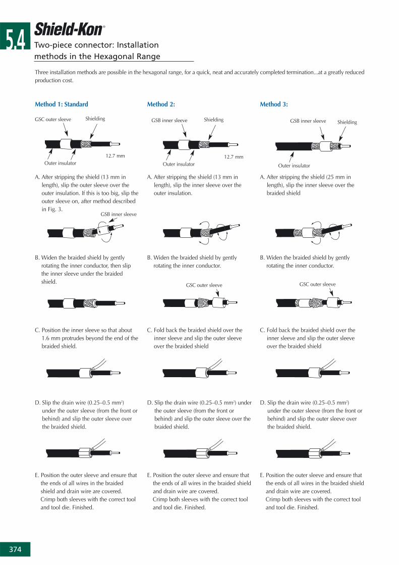
Method 1: Standard
A. After stripping the shield (13 mm inlength), slip the outer sleeve over theouter insulation. If this is too big, slip theouter sleeve on, after method describedin Fig. 3.
B. Widen the braided shield by gentlyrotating the inner conductor, then slipthe inner sleeve under the braidedshield.
C. Position the inner sleeve so that about 1.6 mm protrudes beyond the end of thebraided shield.
D. Slip the drain wire (0.25–0.5 mm2)under the outer sleeve (from the front orbehind) and slip the outer sleeve overthe braided shield.
E. Position the outer sleeve and ensure thatthe ends of all wires in the braidedshield and drain wire are covered.Crimp both sleeves with the correct tooland tool die. Finished.
Method 2:
A. After stripping the shield (13 mm inlength), slip the inner sleeve over theouter insulation.
B. Widen the braided shield by gentlyrotating the inner conductor.
C. Fold back the braided shield over theinner sleeve and slip the outer sleeveover the braided shield
D. Slip the drain wire (0.25–0.5 mm2) underthe outer sleeve (from the front orbehind) and slip the outer sleeve over thebraided shield.
E. Position the outer sleeve and ensure thatthe ends of all wires in the braided shieldand drain wire are covered.Crimp both sleeves with the correct tooland tool die. Finished.
Method 3:
A. After stripping the shield (25 mm inlength), slip the inner sleeve over thebraided shield
B. Widen the braided shield by gentlyrotating the inner conductor.
C. Fold back the braided shield over theinner sleeve and slip the outer sleeveover the braided shield
D. Slip the drain wire (0.25–0.5 mm2)under the outer sleeve (from the front orbehind) and slip the outer sleeve overthe braided shield.
E. Position the outer sleeve and ensure thatthe ends of all wires in the braided shieldand drain wire are covered.Crimp both sleeves with the correct tooland tool die. Finished.
Three installation methods are possible in the hexagonal range, for a quick, neat and accurately completed termination...at a greatly reducedproduction cost.
GSC outer sleeve Shielding
Outer insulator12.7 mm
GSB inner sleeve Shielding
Outer insulator12.7 mm
GSB inner sleeve Shielding
Outer insulator
GSB inner sleeve
GSC outer sleeve GSC outer sleeve
5.4
375
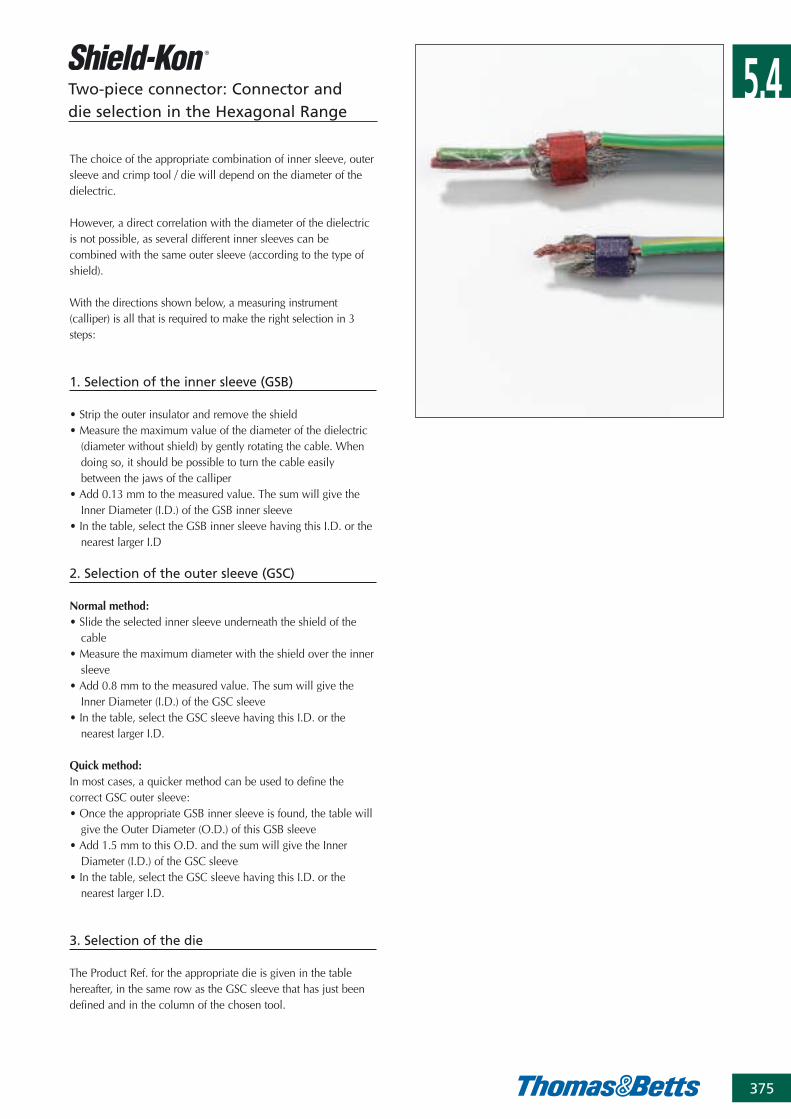
Two-piece connector: Connector and die selection in the Hexagonal Range
The choice of the appropriate combination of inner sleeve, outersleeve and crimp tool / die will depend on the diameter of thedielectric.
However, a direct correlation with the diameter of the dielectricis not possible, as several different inner sleeves can becombined with the same outer sleeve (according to the type ofshield).
With the directions shown below, a measuring instrument(calliper) is all that is required to make the right selection in 3steps:
1. Selection of the inner sleeve (GSB)
• Strip the outer insulator and remove the shield• Measure the maximum value of the diameter of the dielectric
(diameter without shield) by gently rotating the cable. Whendoing so, it should be possible to turn the cable easilybetween the jaws of the calliper
• Add 0.13 mm to the measured value. The sum will give theInner Diameter (I.D.) of the GSB inner sleeve
• In the table, select the GSB inner sleeve having this I.D. or thenearest larger I.D
2. Selection of the outer sleeve (GSC)
Normal method:• Slide the selected inner sleeve underneath the shield of the
cable• Measure the maximum diameter with the shield over the inner
sleeve• Add 0.8 mm to the measured value. The sum will give the
Inner Diameter (I.D.) of the GSC sleeve• In the table, select the GSC sleeve having this I.D. or the
nearest larger I.D.
Quick method:In most cases, a quicker method can be used to define thecorrect GSC outer sleeve:• Once the appropriate GSB inner sleeve is found, the table will
give the Outer Diameter (O.D.) of this GSB sleeve• Add 1.5 mm to this O.D. and the sum will give the Inner
Diameter (I.D.) of the GSC sleeve• In the table, select the GSC sleeve having this I.D. or the
nearest larger I.D.
3. Selection of the die
The Product Ref. for the appropriate die is given in the tablehereafter, in the same row as the GSC sleeve that has just beendefined and in the column of the chosen tool.
5.4
376
Ordering Information
Two-piece connector: Connector and die selection in the Hexagonal Range
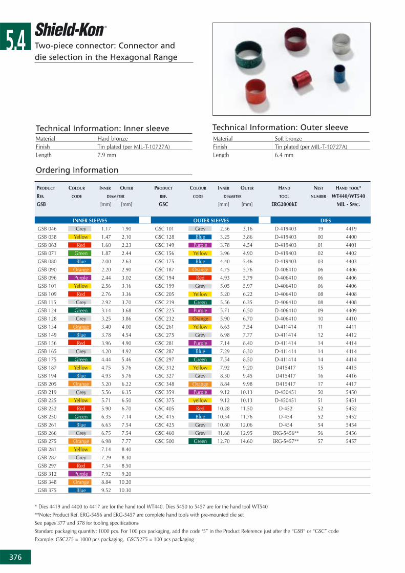
Technical Information: Inner sleeveMaterial Hard bronzeFinish Tin plated (per MIL-T-10727A)Length 7.9 mm
Technical Information: Outer sleeveMaterial Soft bronzeFinish Tin plated (per MIL-T-10727A)Length 6.4 mm
PRODUCT COLOUR INNER OUTER PRODUCT COLOUR INNER OUTER HAND NEST HAND TOOL*
REF. CODE DIAMETER REF. CODE DIAMETER TOOL NUMBER WT440/WT540
GSB [mm] [mm] GSC [mm] [mm] ERG2000KE MIL - SPEC.
INNER SLEEVES OUTER SLEEVES DIES
GSB 046 Grey 1.17 1.90 GSC 101 Grey 2.56 3.16 D-419403 19 4419
GSB 058 Yellow 1.47 2.10 GSC 128 Blue 3.25 3.86 D-419403 00 4400
GSB 063 Red 1.60 2.23 GSC 149 Purple 3.78 4.54 D-419403 01 4401
GSB 071 Green 1.87 2.44 GSC 156 Yellow 3.96 4.90 D-419403 02 4402
GSB 080 Blue 2.00 2.63 GSC 175 Blue 4.40 5.46 D-419403 03 4403
GSB 090 Orange 2.20 2.90 GSC 187 Orange 4.75 5.76 D-406410 06 4406
GSB 096 Purple 2.44 3.02 GSC 194 Red 4.93 5.79 D-406410 06 4406
GSB 101 Yellow 2.56 3.16 GSC 199 Grey 5.05 5.97 D-406410 06 4406
GSB 109 Red 2.76 3.36 GSC 205 Yellow 5.20 6.22 D-406410 08 4408
GSB 115 Grey 2.92 3.70 GSC 219 Green 5.56 6.35 D-406410 08 4408
GSB 124 Green 3.14 3.68 GSC 225 Purple 5.71 6.50 D-406410 09 4409
GSB 128 Grey 3.25 3.86 GSC 232 Orange 5.90 6.70 D-406410 10 4410
GSB 134 Orange 3.40 4.00 GSC 261 Yellow 6.63 7.54 D-411414 11 4411
GSB 149 Blue 3.78 4.54 GSC 275 Grey 6.98 7.77 D-411414 12 4412
GSB 156 Red 3.96 4.90 GSC 281 Purple 7.14 8.40 D-411414 14 4414
GSB 165 Grey 4.20 4.92 GSC 287 Blue 7.29 8.30 D-411414 14 4414
GSB 175 Green 4.44 5.46 GSC 297 Green 7.54 8.50 D-411414 14 4414
GSB 187 Yellow 4.75 5.76 GSC 312 Yellow 7.92 9.20 D415417 15 4415
GSB 194 Blue 4.93 5.76 GSC 327 Grey 8.30 9.45 D415417 16 4416
GSB 205 Orange 5.20 6.22 GSC 348 Orange 8.84 9.98 D415417 17 4417
GSB 219 Grey 5.56 6.35 GSC 359 Purple 9.12 10.13 D-450451 50 5450
GSB 225 Yellow 5.71 6.50 GSC 375 yellow 9.12 10.13 D-450451 51 5451
GSB 232 Red 5.90 6.70 GSC 405 Red 10.28 11.50 D-452 52 5452
GSB 250 Green 6.35 7.14 GSC 415 Blue 10.54 11.76 D-454 52 5452
GSB 261 Blue 6.63 7.54 GSC 425 Grey 10.80 12.06 D-454 54 5454
GSB 266 Grey 6.75 7.54 GSC 460 Grey 11.68 12.95 ERG-5456** 56 5456
GSB 275 Orange 6.98 7.77 GSC 500 Green 12.70 14.60 ERG-5457** 57 5457
GSB 281 Yellow 7.14 8.40
GSB 287 Grey 7.29 8.30
GSB 297 Red 7.54 8.50
GSB 312 Purple 7.92 9.20
GSB 348 Orange 8.84 10.20
GSB 375 Blue 9.52 10.30
* Dies 4419 and 4400 to 4417 are for the hand tool WT440. Dies 5450 to 5457 are for the hand tool WT540
**Note: Product Ref. ERG-5456 and ERG-5457 are complete hand tools with pre-mounted die set
See pages 377 and 378 for tooling specifications
Standard packaging quantity: 1000 pcs. For 100 pcs packaging, add the code ‘5” in the Product Reference just after the “GSB” or “GSC” code
Example: GSC275 = 1000 pcs packaging, GSC5275 = 100 pcs packaging

5.4
377
Two-piece connector: Tooling for the Hexagonal Range
Technical Information: WT-440
Length 203 mmWeight 450 gDies series 4400
Technical Information: WT-540Length 264 mmWeight 540 gDies series 5450
Product Ref.: WT-440 and WT540
• Parallel action hand tool • MIL-specified• Frame, with the option of interchangeable steel dies• A versatile tool, one frame with a selection of dies covers
the whole range of shield diameters in the HexagonalRange
• Shure-Stake™ mechanism: once pressing has commenced,the tool can be re-opened only after successful completionof the crimping cycle
Packaging: wood box containing 1 frame (dies to be orderedseparately, see selection chart page 376 for Product References)
Product Ref.: ERG2000KE
• Ergonomic hand tool • Frame, with the option of Interchangeable steel dies• A versatile tool, one frame with a selection of dies covers a
wide range of shield diameters in the Hexagonal Range, upto Product Ref. GSC425 outer sleeve
• Most dies have several nests (identified with a number) toallow the crimp of several GSC outer sleeves with the samedie set. The appropriate nest number is shown in theselection chart (page 376)
• Shure-Stake™ mechanism: once pressing has commenced,the tool can be re-opened only after successful completionof the crimping cycle
Product Ref.: ERG5456
• Fixed die, ergonomic hand tool • Designed to crimp the GSC460 outer sleeve• Shure-Stake™ mechanism: once pressing has commenced,
the tool can be re-opened only after successful completionof the crimping cycle
• Length: 252 mm• Weight: 460 g
Packaging: cardboard box containing 1 tool with pre-mounted die set
Product Ref.: ERG5457
• Fixed die, ergonomic hand tool • Designed to crimp the GSC500 outer sleeve• Shure-Stake™ mechanism: once pressing has commenced,
the tool can be re-opened only after successful completionof the crimping cycle
• Length: 252 mm• Weight: 460 g
Packaging: cardboard box containing 1 tool with pre-mounteddie set
• Length: 252 mm• Weight: 460 g
Packaging: cardboard box containing 1 frame (dies to be orderedseparately, see selection chart page 376 for Product References)
ERG5456
ERG5457

5.4
378
Two-piece connector: the Circular Range
The Shield-Kon® Connector System for multiple-conductorshielded cable is based on the principle of cold swaging. It usesa two-piece compression connector, which is colour-coded tomatch the proper die. The connector consists of a hard brasscollector inner sleeve (ring) and a soft copper compression outersleeve (ring). Each set of rings and matching installing die willconnect a minimum of 5 shielding braids with one ground wire.The maximum number of braids is limited only by the spacebetween the inner and outer rings.
The design advantages are:
1. Positive selection of inner and outer rings and installing die bya complete colour-coded system.
2. A more reliable grounding termination because only oneground wire connection is made - conventional daisy chainjumper method is eliminated.
3. Smaller, more compact bundle is easy to inspect.4. Only one ground wire is required, however additional ground
wires may be used if needed.5. Smooth insulator protects conductor insulation. 6. With one stroke of the tool, the interlace die will produce a
360° compression uniformly securing all individual shieldsaround the connector.
Two-piece connector:Installation method in the Circular Range
1. After overall insulation is removed to expose shielded cables,each conductor must be freed from the shielding braid. TheThomas & Betts lead extractor tools (see page 380) simplifiesthis operation by pushing the inner conductor through anopening in the shielding braid. The braid is then folded backuntil all conductors are freed.
3. Position the GSC outer ring over the flattened shielding braid,locating it over the centre of the GSB inner ring. Braid may betrimmed even with the edge of the outer compression ringbefore or after compression. Ground wire or wires may beinserted between the outer ring and the shield prior tocompression.
2. Flattened shielding braids are evenly distributed around theperiphery of the GSB inner ring.
5.4
379
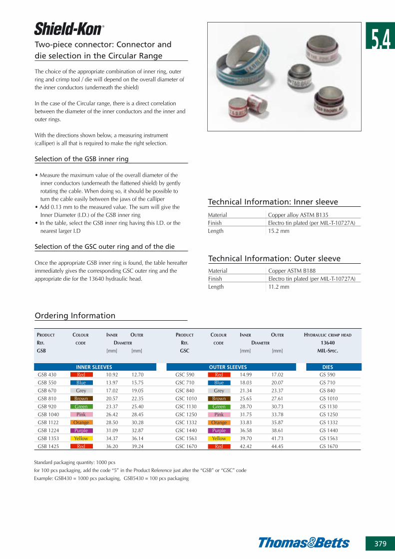
The choice of the appropriate combination of inner ring, outerring and crimp tool / die will depend on the overall diameter ofthe inner conductors (underneath the shield)
In the case of the Circular range, there is a direct correlationbetween the diameter of the inner conductors and the inner andouter rings.
With the directions shown below, a measuring instrument(calliper) is all that is required to make the right selection.
Selection of the GSB inner ring
• Measure the maximum value of the overall diameter of theinner conductors (underneath the flattened shield) by gentlyrotating the cable. When doing so, it should be possible toturn the cable easily between the jaws of the calliper
• Add 0.13 mm to the measured value. The sum will give theInner Diameter (I.D.) of the GSB inner ring
• In the table, select the GSB inner ring having this I.D. or thenearest larger I.D
Selection of the GSC outer ring and of the die
Once the appropriate GSB inner ring is found, the table hereafterimmediately gives the corresponding GSC outer ring and theappropriate die for the 13640 hydraulic head.
Technical Information: Inner sleeve
Material Copper alloy ASTM B135Finish Electro tin plated (per MIL-T-10727A)Length 15.2 mm
Technical Information: Outer sleeveMaterial Copper ASTM B188Finish Electro tin plated (per MIL-T-10727A)Length 11.2 mm
Ordering Information
PRODUCT COLOUR INNER OUTER PRODUCT COLOUR INNER OUTER HYDRAULIC CRIMP HEAD
REF. CODE DIAMETER REF. CODE DIAMETER 13640
GSB [mm] [mm] GSC [mm] [mm] MIL-SPEC.
INNER SLEEVES OUTER SLEEVES DIESGSB 430 Red 10.92 12.70 GSC 590 Red 14.99 17.02 GS 590
GSB 550 Blue 13.97 15.75 GSC 710 Blue 18.03 20.07 GS 710
GSB 670 Grey 17.02 19.05 GSC 840 Grey 21.34 23.37 GS 840
GSB 810 Brown 20.57 22.35 GSC 1010 Brown 25.65 27.61 GS 1010
GSB 920 Green 23.37 25.40 GSC 1130 Green 28.70 30.73 GS 1130
GSB 1040 Pink 26.42 28.45 GSC 1250 Pink 31.75 33.78 GS 1250
GSB 1122 Orange 28.50 30.28 GSC 1332 Orange 33.83 35.87 GS 1332
GSB 1224 Purple 31.09 32.87 GSC 1440 Purple 36.58 38.61 GS 1440
GSB 1353 Yellow 34.37 36.14 GSC 1563 Yellow 39.70 41.73 GS 1563
GSB 1425 Red 36.20 39.24 GSC 1670 Red 42.42 44.45 GS 1670
Standard packaging quantity: 1000 pcs
for 100 pcs packaging, add the code “5” in the Product Reference just after the “GSB” or “GSC” code
Example: GSB430 = 1000 pcs packaging, GSB5430 = 100 pcs packaging
Two-piece connector: Connector and die selection in the Circular Range
5.4
380
Two-piece connector: Tooling for the Circular Range
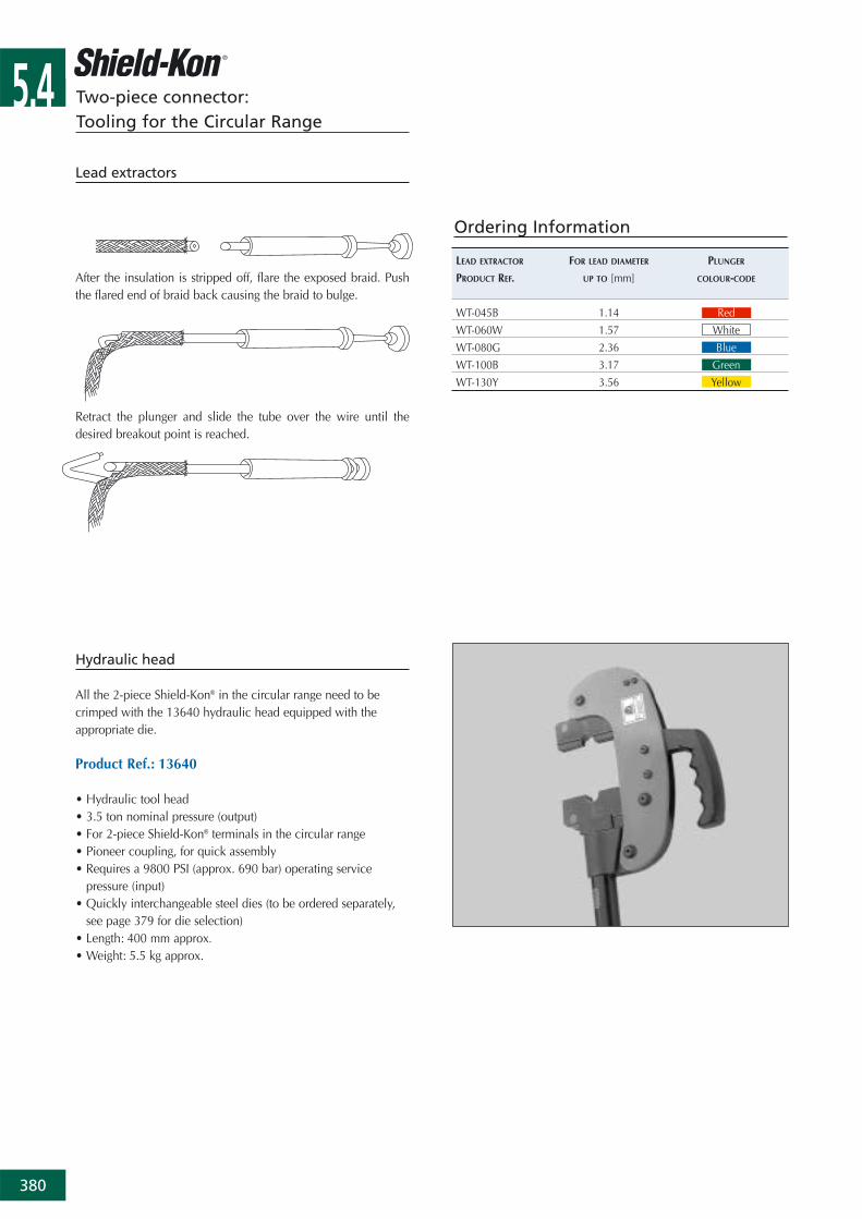
Lead extractors
LEAD EXTRACTOR FOR LEAD DIAMETER PLUNGER
PRODUCT REF. UP TO [mm] COLOUR-CODE
WT-045B 1.14 Red
WT-060W 1.57 White
WT-080G 2.36 Blue
WT-100B 3.17 Green
WT-130Y 3.56 Yellow
Ordering Information
Hydraulic head
All the 2-piece Shield-Kon® in the circular range need to becrimped with the 13640 hydraulic head equipped with theappropriate die.
Product Ref.: 13640
• Hydraulic tool head• 3.5 ton nominal pressure (output)• For 2-piece Shield-Kon® terminals in the circular range• Pioneer coupling, for quick assembly• Requires a 9800 PSI (approx. 690 bar) operating service
pressure (input)• Quickly interchangeable steel dies (to be ordered separately,
see page 379 for die selection)• Length: 400 mm approx.
• Weight: 5.5 kg approx.
After the insulation is stripped off, flare the exposed braid. Pushthe flared end of braid back causing the braid to bulge.
Retract the plunger and slide the tube over the wire until thedesired breakout point is reached.

5.4
381
Two-piece connector: Tooling for the Circular Range
Pumps
A small selection of pumps to operate the 13640 head is shownbelow (please contact your Sales Office for availability of othertypes of pumps).
Product Ref.: 13810E
• Hydraulic pump, electrical power• Service pressure (output): 700 bar• Motor power: 1 1/2 HP - 12 Amp• Voltage & frequency: 230V - 50 Hz• Capability: 3800 cc / min at 14 bar
1000 cc / min at 560 bar • Reservoir volume: 7.6 l• Coupling: Pioneer fitting• Dimensions (L x W x H): 275 x 381x 522 mm• Weight: 27 kg without oil
Accessories:• Product Ref. 13611: hand switch• Product Ref. 13612: foot switch• Product Ref. 13613: hydraulic hose 1.82 m long, with Pioneer
couplings• Product Ref. 21061: hydraulic oil (0.95l can)
Product Ref.: 13606
• Hydraulic pump, foot (or hand) activated • Service pressure (output): 700 bar• Over-pressure security valves • Coupling: Pioneer fitting• Dimensions (L x W x H): 597 x 133 x 165 mm• Weight: 10.4 kg
Accessories:• Product Ref. 13613: hydraulic hose 1.82 m long, with Pioneer
couplings