optical tweezers - aa opto electronic · law. proper explanation of optical trapping behavior...
TRANSCRIPT

OPTICAL TWEEZERSOPTICAL TWEEZERS
AA OPTO-ELECTRONIC QUANTA TECH
A complete Acousto-Optic2 axis deflection setfor optical tweezingapplications
An optical tweezer is a scientific instrument that uses a focused laser beam to provide an attractive or repulsive force, depending on the index mismatch (typically on the order of piconewtons) to physically hold and move microscopic dielectric objects. Op-tical tweezers have been particularly successful in studying a variety of biological systems in recent years.
Dielectric objects are attracted to the center of the beam, slightly above the beam waist, as described in the text. The force applied on the object depends linearly on its displacement from the trap center just as with a simple spring system.
Optical tweezers
General DescriptionOptical tweezers are capable of manipulating nano-meter and micrometer-sized dielectric particles by exerting extremely small forces via a highly focused laser beam. The beam is typically focused by sending it through a microscope objective.
The narrowest point of the focused beam, known as the beam waist, contains a very strong electric field gradient. It turns out that dielectric particles are at-tracted along the gradient to the region of strongest electric field, which is the center of the beam.
The laser light also tends to apply a force on parti-cles in the beam along the direction of beam propa-gation. It is easy to understand why if you imagine li-ght to be a group of tiny particles, each impinging on the tiny dielectric particle in its path. This is known as the scattering force and results in the particle being displaced slightly downstream from the exact position of the beam waist, as seen in the figure.
Optical traps are very sensitive instruments and are capable of the manipulation and detection of sub-nanometer displacements for sub-micron dielectric particles.[9]
For this reason, they are often used to manipulate and study single molecules by interacting with a bead that has been attached to that molecule. DNA and the proteins and enzymes that interact with it are commonly studied in this way.
For quantitative scientific measurements, most opti-cal traps are operated in such a way that the dielec-
tric particle rarely moves far from the trap center. The reason for this is that the force applied to the particle is linear with respect to its displacement from the center of the trap as long as the displa-cement is small. In this way, an optical trap can be compared to a simple spring, which follows Hooke’s law.
Proper explanation of optical trapping behavior de-pends upon the size of the trapped particle relative to the wavelength of light used to trap it. In cases where the dimensions of the particle are greater than this wavelength, a simple ray optics treatment is sufficient. On the other hand, if the wavelength of light exceeds the particle dimensions, then the par-ticles must be treated as tiny electric dipoles in an electric field.
Experimental design, Construction and operation
AA OPTO-ELECTRONIC / QUANTA TECH
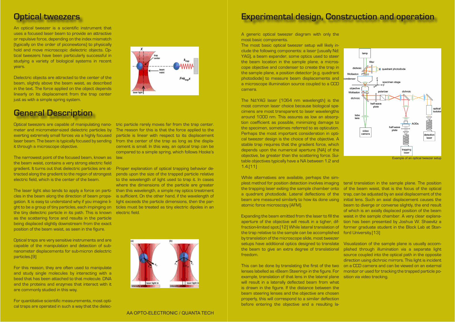
A generic optical tweezer diagram with only the most basic components.The most basic optical tweezer setup will likely in-clude the following components: a laser (usually Nd:YAG), a beam expander, some optics used to steer the beam location in the sample plane, a micros-cope objective and condenser to create the trap in the sample plane, a position detector (e.g. quadrant photodiode) to measure beam displacements and a microscope illumination source coupled to a CCD camera.
The Nd:YAG laser (1064 nm wavelength) is the most common laser choice because biological spe-cimens are most transparent to laser wavelengths around 1000 nm. This assures as low an absorp-tion coefficient as possible, minimizing damage to the specimen, sometimes referred to as opticution. Perhaps the most important consideration in opti-cal tweezer design is the choice of the objective. A stable trap requires that the gradient force, which depends upon the numerical aperture (NA) of the objective, be greater than the scattering force. Sui-table objectives typically have a NA between 1.2 and 1.4.[11]
While alternatives are available, perhaps the sim-plest method for position detection involves imaging the trapping laser exiting the sample chamber onto a quadrant photodiode. Lateral deflections of the beam are measured similarly to how its done using atomic force microscopy (AFM).
Expanding the beam emitted from the laser to fill the aperture of the objective will result in a tigher, dif-fraction-limited spot.[12] While lateral translation of the trap relative to the sample can be accomplished by translation of the microscope slide, most tweezer setups have additional optics designed to translate the beam to give an extra degree of translational freedom.
This can be done by translating the first of the two lenses labelled as «Beam Steering» in the figure. For example, translation of that lens in the lateral plane will result in a laterally deflected beam from what is drawn in the figure. If the distance between the beam steering lenses and the objective are chosen properly, this will correspond to a similar deflection before entering the objective and a resulting la-
teral translation in the sample plane. The position of the beam waist, that is the focus of the optical trap, can be adjusted by an axial displacement of the initial lens. Such an axial displacement causes the beam to diverge or converse slightly, the end result of which is an axially displaced position of the beam waist in the sample chamber. A very clear explana-tion has been presented by Joshua W. Shaevitz a former graduate student in the Block Lab at Stan-ford University.[13]
Visualization of the sample plane is usually accom-plished through illumination via a separate light source coupled into the optical path in the opposite direction using dichroic mirrors. This light is incident on a CCD camera and can be viewed on an external monitor or used for tracking the trapped particle po-sition via video tracking.
Example of an optical tweezer setup

Descriptions of various optical tweezer setups
Optical tweezers based on alternate laser beam modes
The majority of optical tweezers make use of con-ventional TEM00 Gaussian beams. However a num-ber of other beam types have been used to trap par-ticles, including high order laser beams i.e Hermite Gaussian beam (TEMxy), Laguerre-Gaussian (LG) beams (TEMpl) and Bessel beams.
Optical tweezers based on Laguerre Gaussian beam have the unique capability of trapping parti-cles that are optically reflective and absorptive. La-guerre-Gaussian beams also possess a well-defined orbital angular momentum that can rotate parti-cles.[14][15] This is accomplished without external mechanical or electrical steering of the beam.
Both zeroth and higher Bessel Beams also possess a unique tweezing ability. They can trap and rotate multiple particles that are millimeters apart and even around obstacles. [16]
Micromachines can be driven by these unique opti-cal beams due to their intrinsic rotating mechanism due to the spin and orbital angular momentum of light.[citation needed]
Multiplexed optical tweezers
A typical setup uses one laser to create one or two traps. More complex optical tweezing operations can be achieved either by time-sharing a single la-ser beam among several optical tweezers or by dif-fractively splitting the beam into multiple traps. With acousto-optic deflectors or galvanometer-driven mirrors, a single laser beam can be shared among hundreds of optical tweezers in the focal plane, or else spread into an extended one-dimensional trap. Specially designed diffractive optical elements can divide a single input beam into hundreds of conti-nuously illuminated traps in arbitrary three-dimen-sional configurations. The trap-forming hologram also can specify the mode structure of each trap individually, thereby creating arrays of optical vor-tices, optical tweezers, and holographic line traps, for example. When implemented with a spatial light modulator, such holographic optical traps also can move objects in three dimensions.
Optical tweezers based on optical fibers
The fiber optical trap relies on the same principle as the optical trapping, but with the laser delivered through an Optical fiber. If one end of the optical fi-ber tip is moulded into a lens-like facet, that lens tip will act as a focusing (converging) point for the high optical gradient trap to be formed.[17]
On the other hand, if the ends of the fiber are not moulded, the laser exiting the fiber will be diverging and thus a stable optical trap can only be realised by balancing the gradient and the scattering force from two opposing ends of the fiber. The gradient force will trap the particles the transverse direction, while the axial optical force comes from the scat-tering force of the two counter propagating beams emerging from the two fibers. The equilibrium z-position of such a trapped bead is where the two scattering forces equal each other. This work was pioneered by A. Constable et al., Opt. Lett. 18,1867 (1993), and followed by J.Guck et al., Phys. Rev. Lett. 84, 5451 (2000), who made use of this technique to stretch microparticles. By manipulating the input power into the two ends of the fiber, there will be an increase of a «optical stretching» that can be used to measure viscoelas-tic properties of cells, with sensitivity sufficient to distinguish between different individual cytoskeletal phenotypes. i.e. human erythrocytes and mouse fibroblasts. A recent test has seen great success in differentiating cancerous cells from non-cance-rous ones from the two opposed, non-focused laser beams.[citation needed]
Optical tweezers in a ‘landscape’ (cell sorting)
One of the more common cell sorting systems make use of flow cytometry through fluorescent imaging. In this method, a suspension of biologic cells is sor-ted into two or more containers, based upon speci-fic fluorescent characteristics of each cell during an assisted flow. By using an electrical charge that the cell is «trapped» in, the cell are then sorted based on the fluorescence intensity measurements. The sorting process is undertaking by an electrostatic deflection system that diverts cell into containers based upon their charge.
In the optically actuated sorting process, the cell are flowed through into an optical landscape i.e 2D or 3D optical lattices. Without any induce electrical charge, the cell would sorting based on their intrin-sic refractive index properties and can be re-con-figurability for dynamic sorting. Mike MacDonald, Gabe Spalding and Kishan Dholakia, Nature 426, 421-424 (2003)[1] made use of diffractive optics and optical elements to create the optical lattice. An automated cell sorter was described at the Univer-sity of Toronto in 2001, but made use of mechanical parameters as opposed to spatial light modulation [18]
On the other hand, K. Ladavac, K. Kasza and D. G. Grier, Physical Review E 70, 010901(R) (2004)[2] made use of the spatial light modulator to project an intensity pattern to enable the optical sorting pro-cess.The main mechanism for sorting is the arrangement of the optical lattice points. As the cell flow throu-gh the optical lattice, there are forces due to the particles drag force that is competing directly with the optical gradient force(See Physics of an Optical Tweezers) from the optical lattice point. By shifting the arrangement of the optical lattice point, there is a preferred optical path where the optical forces are dominate and biased. With the aid of the flow of the cells, there is a resultant forces that is directed along that preferred optical path. Hence, there is a relationship of the flow rate with the optical gradient force. By adjusted the two forces, one will be able to obtain a good optical sorting efficiency.
Competition of the forces in the sorting environment need fine tuning to succeed in high efficient optical sorting. The need is mainly with regards to the ba-lanced of the forces; drag force due to fluid flow and
optical gradient force due to arrangement of inten-sity spot.
Scientists at the University of St. Andrews have re-ceived considerable funding from the UK Engineering and Physical Sciences Research Council (EPSRC) for an optical sorting machine. This new technology could rival the conventional fluorescence-activated cell sorting.[19]
Optical tweezers based on evanescent fields
An evanescent field [3] [4] is a residue optical field that «leaks» during total internal reflection. This «lea-king» of light fades off at an exponential rate. The evanescent field has found a number of applications in nanometer resolution imaging (microscopy); opti-cal micromanipulation (optical tweezers) are beco-ming ever more relevant in research.
In optical tweezers, a continuous evanescent field can be created when light is propagating through an optical waveguide (multiple total internal reflec-tion). The resulting evanescent field has a directional sense and will propel microparticles along its pro-pagating path. This work was first pioneered by S. Kawata and T. Sugiura, in 1992 (Opt. Lett. 17 (11), 772 (1992)). Kawata showed that the field can be coupled to the particles in proximity on the order of 100 nanometers.
This direct coupling of the field is treated as a type of photon tunnelling across the gap from prism to microparticles. The result is a directional optical propelling force.
A recent updated version of the evanescent field op-tical tweezers make use of extended optical lands-cape patterns to simultaneously guide a large num-ber of particles into a preferred direction without using a waveguide. It is termed as Lensless Optical Trapping (“LOT”) [5]. The orderly movement of the particles is aided by the introduction of Ronchi Ru-ling that creates well-defined optical potential wells (replacing the waveguide). This means that particles are propelled by the evanescent field while being trapped by the linear bright fringes. At the moment, there are scientists working on focused evanescent fields as well.

Optical tweezers: an indirect approach
Ming Wu, a UC Berkeley Professor of electrical en-gineering and computer sciences invented the new optoelectronic tweezers.Wu transformed the optical energy from low powe-red light emitting diodes (LED) into electrical energy via a photoconductive surface. The ideas is to allow the LED to switch on and off the photoconductive material via its fine projection. As the optical pattern can be easily transformable through optical projec-tion, this method allow a high flexibility of switching different optical landscapes.
The manipulation/tweezing process is done by the variations between the electric field actuated by the light pattern. As the particles will be either attracted or repelled from the actuated point due to the its in-duced electrical dipole. Particles being suspended in a liquid will be susceptible to electrical field gradient, this is known as dielectrophoresis.
One clear advantage is that the electrical conductivi-ty between a different cells. Living cells have a lower conductive medium while the dead ones have mini-mum or no conductive medium. The system may be able to manipulate roughly 10,000 cells or particles at the same time.See comments by Professor Kishan Dholakia on this new technique, K. Dholakia, Nature Materials 4, 579-580 (01 Aug 2005) News and Views
Optical binding
When a cluster of microparticles are trapped wi-thin a monochromatic laser beam, the organisation of the microparticles within the optical trapping is heavily dependent on the redistributing of the optical trapping forces amongst the microparticles. This redistribution of light forces amongst the cluster microparticles provides a new force equilibrium on the cluster as a whole. As such we can say that the cluster of microparticles are somewhat bounded to-gether by light. One of the first evidence of optical binding was reported by Michael M. Burns, Jean-Marc Fournier, and Jene A. Golovchenko [6].
References
1. Ashkin, A. «Phys. Rev. Lett. 24, 156-159», (1970) 2. A Ashkin, J M Dziedzic, J E Bjorkholm and S Chu, Opt. Lett. 11, 288-290, 1986. 3. Hill, Murray (November 1987). «wrote the book on atom trapping». Retrieved June 25, 2005.Interview conducted for internal newsletter at Bell Labs. Contains confirmation of Ashkin as the inventor of optical trapping and provides information on the 1997 Nobel Prize in Physics. 4. «Conversations with History: An Interview with Steven Chu» (2004), Institute of International Studies, UC Berkeley. Last accessed on September 2, 2006. 5. Ashkin, A. et al «Science vol. 235, iss. 4795, pp. 1517» (1987) 6. Macdonald MP, Spalding GC, Dholakia K, «Microfluidic sor-ting in an optical lattice., Nature (2003); 421: 421-424. 7. Koss BA, Grier DG, «Optical Peristalsis» 8. Applegate, Jr. R. W. et al Optics Express vol. 12, iss. 19, pp. 4390 (2004) 9. Moffitt JR, Chemla YR, Izhaky D, Bustamante C, «Differen-tial detection of dual traps improves the spatial resolution of optical tweezers», PNAS (2006); 103(24): 9006-9011. 10. Gordon JP, «Radiation Forces and Momenta in Dielectric Media», Physical Review A (1973). 8(1): 14-21. 11. Neuman KC, Block SM, «Optical trapping», Review of Scientific Instruments (2004); 75(9): 2787-2809. 12. Svoboda K, Block SM, «Biological Application of Optical Forces», Annual Reviews of Biophysics and Biomolecular Structure (1994); 23:247-285. 13. Shaevitz JW, «A Practical Guide to Optical Trapping» (August 22, 2006). Last accessed on September 12, 2006. 14. Curtis JE, Grier DG, «Structure of Optical Vortices» (2003). Last accessed on September 3, 2006. 15. Padgett M, «Optical Spanners». Last accessed on Sep-tember 3, 2006. 16. McGloin D, Garces-Chavez V, Paterson L, Carruthers T, Melvil H, Dholakia K, «Bessel Beams». Last accessed on September 3, 2006. 17. Hu Z, Wang J, Liang J, «Manipulation and arrangement of biological and dielectric particles by a lensed fiber probe», Optics Express, 12 (17): 4123-4128 (2004). 18. Grover SC et al., Automated single-cell sorting system based on optical trapping. J Biomed Opt. 2001 Jan;6(1):14-22. 19. «Optical fractionation and sorting.», IRC Scotland. Last accessed on September 3, 2006.
2 Dimensional Acousto-Optic deflector
These deflectors offer a typical total resolution of 160 000 dots (2 axis) with a round input laser beam up to 6.7 mm (1/e²). Main advantage is the large scan angle which can reach up to 3 x 3 degrees. With an adapted frequency driver, this two axis deflector is a very powerfull tool for optical tweezing applications.
DTSXY-400Material-Acoustic mode TeO2 [S]Acoustic Velocity Nom V=650 m/sOptical Wavelength range 1064 nm or single in [350-1600 nm]Transmission > 95 % per axis (broadband coating)Optical Input / Output polarizations Linear orthogonalAperture 7.5 x 7.5 mm²
(Beam diameter 6.7 mm)Carrier frequency / Frequency shift Wavelength dependentFrequency range 30 MHz @1064 nmScan angle 49 x 49 mrd² @1064 nmDiffraction efficiency > 50 % across frequency range (2 axis)Access time 10.3 µs (beam dia 6.7 mm)Resolution (N) 240x240 @1064 nmStatic extinction ratio > 2000/1Max optical power density > 10 W / mm² @1064 nmInput impedance Nom 50 OhmsV.S.W.R. Nom < 2/1RF Power < 2 Watts @1064 nm (per axis)Connectors SMAOperating Temperature 10 to 40°C
Note : AA also propose Version DTSXY-250 with an aperture of 4.5 x 4.5 mm²

High Resolution Direct Digital Synthesizers (DDSA)
These Direct Digital Synthesizers are dedicated to high accuracy applications for which high resolution is the key factor.A PC interface board will be used to control the frequency (15-31 bits) as well as the latch of the frequency (1 bit E/D). These drivers are used in combination with AA amplifiers.
High Stability
High AccuracyPositionning accuracy < 0.5 nrad with DDSA 31 bits
Frequency range 10 to 350 MHz Frequency stability/accuracy Nom +/- 1 ppm / °C Frequency step Nom 15 KHz (15 bits)
Nom 1 KHz (23 bits)Nom 0.25 Hz (31 bits)
Commutation time < 40 ns (15 bits)< 64 ns (23 bits)< 80 ns (31 bits)
Frequency control 15, 23, 31 bits digital + 1 bit Enable/disableRise time / Fall time (10-90 %) < 10 ns analog (< 100 ns 8 bits)Modulation input control Analog 0-5 V / 50 ohms (8 bits on request)Extinction ratio > 40 dB for F < 250 MHzHarmonics H2 > 30 dBcOutput RF power Nom 0 dBm (to be associated with AA Amplifier)Output impedance 50 ohmsV.S.W.R. < 1.2 : 1Power supply OEM version : 15-28 VDC – nom 320 mA @24 VDC
Laboratory version 4 : 110-230 VAC – 50-60 HzInput / Output connectors SMA, HD44 / SMASize OEM version : 129 x 61 x 55 mm3
Laboratory version 4 : 310 x 250 x 105 mm3Cooling Conduction through baseplateMaximimun case temperature 50 °COperating temperature 10 to 40 °C
Associated RF Power amplifiers (AMPA)
Frequency range 1 Watt : 20-450 MHz2 watts : 20-600 MHz
Gain 1 Watt : nom 33 dB2 watts : nom 40 dB
Gain Flatness Nom +/- 0.5 dB, < +/1 dB Noise Figure 1 Watt : nom 5 dB
2 watts : nom 7 dBOutput RF Power (1 dB compression) > 30 dBm (> 29.5 dBm @ <40 MHz), 1 Watt
> 33 dBm , 2 WattsOutput Impedance 50 OhmsCLASS APower supply3 1 Watt : 24 +/- 0.5 VDC - < 340 mA
2 watts : 24 +/- 0.5 VDC - < 500 mA
Input / Output connectors SMA femaleSize 76 x 40 x 42 mm3Heat exchange Conduction through baseplate Operating temperature -10 to +55 °C
USB Controller (USB-CTRL-DDS)
AA propose an external USB controller suitable to drive high resolution Direct Digital Synthesizers. Its USB 2.0 interface will allow user a fast and easy set up to drive one axis or two axis synthesizers for variable frequency shifters, one axis deflectors or two axis deflectors.This USB controller is compatible with the 15, 23 and 31 bits DDS drivers.
Computer USB Controller DDS Amplifier AO device