owners manual - ecowaterecowater.bg/assets/uploads/en/ecowater pf (1).pdf · owners manual how to...
TRANSCRIPT

Part No. 7260017 EURO (Rev. B 9/16/04)Manufactured by EcoWater Systems
P.O. Box 64420 St.Paul MN 55164 - 9888
OWNERSMANUALHow to maintain and operate yourEcoWater multi--purpose filter
SERIESETF2100 PF
Version 10.2005

3
2
Unpacking, Table of ContentsECOWATERS Y S T E M S
UNPACKING
EcoWater Multi--Purpose Filters are shipped fromthe factory in one master carton consisting of ......Mineral tank and valve assembly...Controller cover and timer assembly...Skin--pack of small parts (includes this manual)NOTE: Filtering mineral is not included. Seepage 22 for ordering information.Thoroughly check the filter for possible shippingdamage and parts loss. Also inspect and note anydamage to the shipping carton. Notify the trans-portation company if damage is present. EcoWateris not responsible for in--transit damages.Remove and discard (RECYCLE) all packing materi-als. We suggest that you do not remove the smallparts on the skin--pack until you are ready to usethem. Filter assembly instructions are on page 5.
TABLE OF CONTENTS
Page
Safety Guides 3
Specifications / Dimensions 4
Assembly Instructions 5
Planning Installation 6 -- 8
Installation Steps 9 -- 11
Programming Face Plate Timer 12 -- 13
Filter Operation 14 -- 16
General 14
Service / Backwash / Fast Rinse 15
Service Information 17 -- 20
Neutralizing Filter 17
Taste & Odor Filter 17
Troubleshooting 18
Wiring Schematic 20
Repair Parts 21 -- 24
European Directive 2002/96/EC requires all electrical and electronicequipment to be disposed of according to Waste Electrical and Electronic Equipment(WEEE) requirements. This directive or similar laws are in place nationally and can varyfrom region to region. Please refer to your state and local laws for proper disposal of thisequipment.

3
3
Safety GuidesECOWATERS Y S T E M S
SAFETY GUIDES
Follow the installation instructions carefully. Failureto install the filter properly voids the warranty.Before you begin installation, read this entire manu-al. Then, obtain all the materials and tools you willneed to make the installation.Check local plumbing and electrical codes. Theinstallation must conform to them.Use only lead--free solder and flux for allsweat-solder connections, as required by state andfederal codes.Use care when handling the filter. Do not turn upsidedown, drop, or set on sharp protrusions.Do not locate the filter where freezing temperaturesoccur. Do not attempt to filter water over 49°C.Freezing, or hot water damage voids the warran-ty.Avoid installing in direct sunlight. Excessive sunheat may cause distortion or other damage to non--metallic parts.The filter requires a minimum water flow (see specifi-cations) at the inlet. Maximum allowable inlet wa-ter pressure is 8.7 bar. If daytime pressure is over5.6 bar, nighttime pressure may exceed the maxi-mum. Use a pressure reducing valve if necessary.Adding a pressure reducing valve may reduce theflow.This filter works on 24 volt--50 hz electrical pow-er only. Be sure to use the included transformer andplug it into a nominal 220--240 VAC, 50 Hz house-hold outlet that is grounded and properly protectedby an over current device such as a circuit breakeror fuse. If transformer is replaced use only the autho-rized service, class II, 24 volt, 10VA transformer.This system is not intended to be used for treatingwater that is microbiologically unsafe or of unknownquality without adequate disinfection before or afterthe system.

35.5 cm
35.5 cm
A
B
3
4
Specifications / DimensionsECOWATERS Y S T E M S
ETF2100PF1010” DIA x 47”RESIN TANK
ETF2100PF1212” DIA x 54”RESIN TANK
FILTER TYPE, Mineral ¡SEDIMENT REMOVALFilter Aggregate limits
factory recommendationbased on water analysis
ACID NEUTRALIZERNeutralite
water supplypH limits
6.0 to 6.8 6.0 to 6.8
TASTE & ODOR REMOVALActivated Carbon limits
factory recommendationbased on water analysis
AMOUNT MINERAL RECOMMENDED (cu. ft.) 1 to 1--1/4 2
AMOUNT GRAVEL (kg.) 7.7 13.1
AMOUNT FILTER SAND RECOMMENDED (kg.) ¡ 4.5 16.3 -- 16.8
SUPPLY WATER PRESSURE LIMITS (Bar) 1.4 -- 8.6 1.4 -- 8.6
SUPPLY WATER TEMPERATURE LIMITS (_C) 4 -- 49 4 -- 49
MINIMUM INLET WATER FLOW,BACKWASH AND FAST RINSEFLOW TO DRAIN (Litres / Min.)
19 26.6
BACKWASH TIME (MINUTES) © 25 25
FAST RINSE TIME (MINUTES) © 5 5
¡ not included with filter © Default times -- cycle length is adjustable
A B
ETF2100PF10 145 cm 159 cm
ETF2100PF12 127 cm 141.5 cm
3
5
Assembly InstructionsECOWATERS Y S T E M S
FILL THE MINERAL TANK
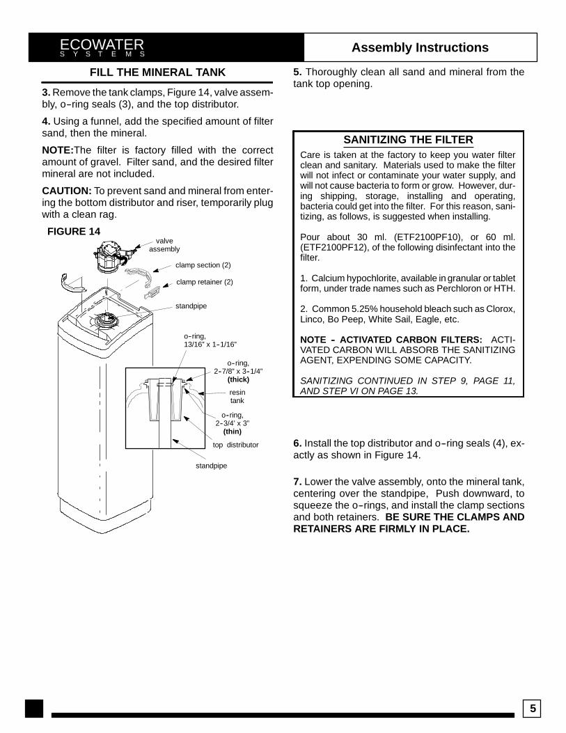
3. Remove the tank clamps, Figure 14, valve assem-bly, o--ring seals (3), and the top distributor.
4. Using a funnel, add the specified amount of filtersand, then the mineral.
NOTE:The filter is factory filled with the correctamount of gravel. Filter sand, and the desired filtermineral are not included.
CAUTION: To prevent sand and mineral from enter-ing the bottom distributor and riser, temporarily plugwith a clean rag.
standpipe
top distributor
resintank
valveassembly
clamp retainer (2)
clamp section (2)
o--ring,13/16” x 1--1/16”
o--ring,2--7/8” x 3--1/4”
(thick)
o--ring,2--3/4’ x 3”
(thin)
standpipe
FIGURE 14
5. Thoroughly clean all sand and mineral from thetank top opening.
SANITIZING THE FILTERCare is taken at the factory to keep you water filterclean and sanitary. Materials used to make the filterwill not infect or contaminate your water supply, andwill not cause bacteria to form or grow. However, dur-ing shipping, storage, installing and operating,bacteria could get into the filter. For this reason, sani-tizing, as follows, is suggested when installing.
Pour about 30 ml. (ETF2100PF10), or 60 ml.(ETF2100PF12), of the following disinfectant into thefilter.
1. Calcium hypochlorite, available in granular or tabletform, under trade names such as Perchloron or HTH.
2. Common 5.25% household bleach such as Clorox,Linco, Bo Peep, White Sail, Eagle, etc.
NOTE -- ACTIVATED CARBON FILTERS: ACTI-VATED CARBON WILL ABSORB THE SANITIZINGAGENT, EXPENDING SOME CAPACITY.
SANITIZING CONTINUED IN STEP 9, PAGE 11,AND STEP VI ON PAGE 13.
6. Install the top distributor and o--ring seals (4), ex-actly as shown in Figure 14.
7. Lower the valve assembly, onto the mineral tank,centering over the standpipe, Push downward, tosqueeze the o--rings, and install the clamp sectionsand both retainers. BE SURE THE CLAMPS ANDRETAINERS ARE FIRMLY IN PLACE.

3
6
Planning InstallationECOWATERS Y S T E M S
TYPICAL INSTALLATION DRAWINGS
INLET -- OUTLET OPTIONS
1” copper tube(2 supplied)
1” x 1” sweat
1” x 3/4” sweat
1” sweat x 1”or 3/4” pipethread
floor drain
floor drain
NOTE: Faceplate and supportnot shown for clarity of drawing.
Tie or wire valve drain hose in place,to keep over floor drain.
valve drain hose
valve drain hose
4 cmairgap
220--240VAC , 50Hz
outlet
transformer(supplied)
to timer
to timer
4 cmairgap
INLET
INLET
OUTLET
OUTLET
3-- valvebypass system
inlet valve
outlet valve
bypass valve
UNFILTEREDWATERUNFILTERED
WATER
FILTEREDWATER
OUTSIDEFAUCETS
OUTSIDEFAUCETS
FIGURE 15
INLET -- OUTLET PLUMBING OPTIONS
1. ALWAYS INSTALL either an EcoWater bypassvalve, #7214383, or a 3 valve bypass system. If thebypass is equiped with a bleedscrew be sure to com-pletely cose it.2. Use 1”... or, 3/4” (minimum) pipe and fittings.3. Use sweat copper... or, threaded pipe*... or, PVCplastic pipe.**Sweat soldering is required to adapt to the fittings(1” male) supplied with the filter, or obtain approvedcompression adaptors. The following special fittingsare available from EcoWater. Be sure to complywith all local plumbing codes.
OPTIONAL INLET/OUTLET FITTINGS
#7104546 PVC Nipple --- Use in place ofincluded copper inlet and outlet tubes.
#7129211 Adaptor Fitting, 1–1/2” (2) --- Use inplace of included copper inlet and outlet tubes.
#7120259 Elbow --- Extends inlet and/oroutlet in any 90˚ direction.

3
7
OTHER REQUIREMENTS
4. A drain is needed for regeneration discharge wa-ter. A floor drain, close to the filter is preferred. Alaundry tub, standpipe, etc., are other options.
CAUTION: DRAIN WATER EXITS THE HOSE AT AFAST FLOW RATE, AND AT WATER SYSTEM
PRESSURE. BE SURE THE HOSE IS FASTENEDIN SOME MANNER TO PREVENT “WHIPPING”,AND SPLASHING TO PREVENT WATER DAMAGETO SURROUNDING AREA.
5. A 220--240VAC--50Hz, grounded electrical outlet(continuously “live” is need within 2 meters of the fil-ter.

3
8
Planning InstallationECOWATERS Y S T E M S
TOOLS YOU MAY NEED
D common screwdriver D pliers
D cross--point screwdriver D tape measure
SOLDERED COPPER THREADED CPVC PLASTIC
D tubing cutter D hacksaw orpipe cutter
D hacksaw
D propane torch D threading tool D adjustablewrench
D LEAD--FREEsolder and flux
D pipe joint com-pound*
D solvent cement*
D emery cloth,sandpaper or steelwool
D primer
MATERIALS YOU MAY NEED
H bypass valve, or 3 valvesH pipe and fittings as requiredH 5/8” I. D. minimum drain hose, either standard gar-den hose, or hose onto a barb fitting*
*VALVE DRAIN OPTIONS: Flexible drain hose isnot allowed in all localities (check your codes). Fora rigid valve drain run, plumb according to localcodes. To connect to the valve drain fitting, purchasean adaptor, garden hose thread x 5/8” (minimum)tube. Use a hacksaw to cut off barbs from the fitting.
SELECT INSTALLATION LOCATION
Consider all of the following when selecting aninstallation location for the filter selected.
S To filter all water in the home, install the filter closeto the water supply inlet. To conserve filtered wa-ter, outside faucets should remain on raw water.
S If other water conditioning equipment is installed,locate as shown in Figure 16.
S A nearby drain is needed to carry away regenera-tion discharge water. A floor drain is preferred,with a laundry tub, standpipe, etc., as other op-tions (check your local codes).
S The filter works on 24 volts only. A transformer isincluded (FOR INDOOR USE) to reduce220--240 VAC--50 Hz house electrical power.Provide an approved, grounded outlet within 2 mof the filter. The transformer has an attached 2 mpower cable for connection between the outletand the timer.
S Position the filter at least 15 cm from surroundingwalls, or other appliances, to allow access forservicing.
S If installing the filter in an outside location, be sureto provide protection from the elements, contami-nation, vandalism, and sunlight heat. The sun’sheat can melt plastic parts.
FIGURE16

3
9
InstallationECOWATERS Y S T E M S
1. INSTALL INLET AND OUTLET FITTINGS
NOTE: All fittings are on the small parts skin pack.
a. Insert the turbine support, into the valve outletport, up to the shoulder.
NOTE: If installing the EcoWater bypass valve,close the optional bleedscrew is present.
b. Slide a lubricated o--ring onto one of the coppertubes. Carefully insert the copper tube into the outletport (Figure 17) and secure in place with a plastic “C”clip.
NOTE: For lubrication, use silicone grease ap-proved for use on potable water supplies.
c. Repeat step b on the inlet side.
2. TURN OFF WATER SUPPLY
a. Close the main water supply valve, near wellpump or water meter.
b. Shut off the electricity or fuel supply to the waterheater.
c. Open high and low faucets to drain all water fromhose pipes.
3. INSTALLING 3--VALVE BYPASS
If installing a 3--valve bypass system, plumb asneeded, using Figure 15 on page 6 as a guide. Ifinstalling sweat copper, be sure to USE LEAD--FREE SOLDER as required by federal and Statecodes. Use pipe joint compound on outside pipethreads.
4. MOVE FILTER INTO PLACE
Move the filter into the installation position, settingon a solid. smooth and level surface. If needed,place the filter on a section of 2 cm plywood. Thenshim under the plywood to level the filter Figure 18.
CAUTION: DO NOT PLACE SHIMS DIRECTLY UN-DER THE SHROUD. The weight of the tank maycause the shroud to fracture at the shim.
5. ASSEMBLE INLET AND OUTLET PLUMBING
Measure, cut and loosely assemble pipe and fittingsfrom the main water pipe (or from bypass valvesinstalled in step 3), to the filter inlet and outlet coppertubes.
BE SURE UNFILTERED WATER SUPPLY PIPEGOES TO THE FILTER INLET SIDE. Trace the wa-ter flow direction to be sure.
VALVEINLET
o--ring seal (2)
1” copper tube (2)
clip (2)
support
FIGURE17
FIGURE18
shroud
2 cm plywoodshim

3
10
InstallationECOWATERS Y S T E M S
6. COLD WATER PIPE GROUNDING
The house cold water pipe (metal only) is often usedas a ground for the house electrical system. The3--valve bypass type if installation, shown in Figure15, will maintain ground continuity. If you use theplastic bypass valve at the filter, continuity is broken.To restore the ground, install one of the followinggrounds.
a. Use the included hose clamps and wire to jumperacross the inlet and outlet copper tubes Figure 19a.
NOTE: Hose clamps must be placed on pipes beforesoldering.
b. Install a #4 copper wire across the removed sec-tion of main water pipe, securely clamping on bothends (Figure 19b).
7. CONNECT INLET & OUTLET PLUMBING
Complete the inlet and outlet plumbing as applica-ble.
a. SOLDERED COPPER
(1) Thoroughly clean and flux all joints.
(2) Remove the inlet and outlet tubes from the valve(pull plastic “C” clips), and o--rings from the tubes.DO NOT SOLDER WITH TUBES IN THE VALVE.SOLDERING HEAT WILL DAMAGE THE VALVE.
(3) Make all solder connections. Be sure to keep fit-tings fully together, and pipes square and straight.
NOTE: If using ground (step 6a), hose clamps mustbe placed on pipes before soldering.
(4) AFTER PLUMBING HAS COOLED, repeatsteps 1b and 1c.
b. THREADED PIPE
(1) Apply pipe joint compound to all outside pipethreads.
(2) Tighten all threaded joints.
(3) If SOLDERING TO INLET AND OUTLETTUBES, observe steps (1) through (4) above.
c. CPVC PLASTIC PIPE
(1) Clean, prime and cement all joints (follow instruc-tions of the plastic pipe and fittings manufacturer).
(2) IF SOLDERING TO INLET AND OUTLETTUBES, observe preceding steps (1) through (4).
8. INSTALL VALVE DRAIN HOSE
a. Connect a length of 5/8” I.D. (minimum) hose tothe valve drain elbow on the controller Figure 15.The elbow accepts either a hose onto the barb fit-ting, or standard garden hose onto the threads. Touse the threads, cut off the barbs with a hacksaw.
NOTE: Flexible drain hose is not allowed in all locali-ties. See option on page 7.
b. Run the hose to a floor drain, and as typicallyshown in Figure 15, tie or wire the end to a brick orother heavy object. This will prevent “whipping” dur-ing regenerations. Be sure to provide a 4 cm mini-mum air gap, to prevent possible sewer water back-up.
ground wire
clamp (2)
FIGURE 19 FIGURE 20
B
A 3 -- Valve Bypass
OUTLETVALVE
INLETVALVEBYPASS
VALVE
to conditionerfrom conditioner
EcoWaterBypass Valve
D for SERVICE:-- Open the inlet and outlet
valves.-- Close the bypass valve.
D for BYPASS:-- Close the inlet and outlet
valves.-- Open the bypass valve.
PUSH INfor bypass
PULL OUTfor service
Install hose clamps beforesoldering copper tubes
coppertubes
hose clamp,ground (2) ground wire

3
11
InstallationECOWATERS Y S T E M S
NOTE: In addition to a floor drain, you can use alaundry tub or stand pipe as a good drain point forthis hose. Avoid long drain hose runs, or elevatingthe hose.
9. PRESSURE TESTING FOR LEAKS
TO PREVENT EXCESSIVE AIR PRESSURE INTHE FILTER AND PLUMBING SYSTEM, DO THEFOLLOWING STEPS IN ORDER
a. Open two or more filtered water faucets, both hotand cold.
b. Referring to Figure 20, turn the bypass valves toservice position.
c. Slowly open the main water supply valve.
d. Close the filtered water faucets after both of thefollowing occur.-- water runs smoothly, with no air bubbles-- you can smell the sanitizing (page 5) bleach odorat the faucets
e. Check your complete installation for leaks. If re-work is required, be sure to observe precautions instep 6.
10. CONNECT ALL LEADWIRES
a. Connect the wire harness to the valve switch Fig-ure 21. The switch is on the valve, by the large gear.
NOTE: Check to be sure the connector is secure, onthe back of the timer.
b. Attach the male connector, on the valve motorleadwire, the the matching female connector on thefaceplate timer.
c. Connect the power cable leads to the back of thetimer.
11. CONNECT TO ELECTRICAL POWER
Connect the timer power cable leads to the two ter-minals on the transformer FIGURE 9. Plug the trans-former into a continuously “live”, grounded,220--240VAC--50Hz house electrical outlet, ap-proved by local codes.
12. TO COMPLETE INSTALLATION, DO THE PRO-GRAMMING STEPS ON PAGES 12 AND 13.
NOTE: SEE WATER HEATER START--UP ONPAGE .
FIGURE 21
Transformer
24V positionswitch
BACK OF TIMER
220--240VAC 50Hz POWERSOURCE
valvemotor

3
12
Programming Face Plate TimerECOWATERS Y S T E M S
FIGURE 22DOWN keypadUP keypaddisplay
SELECT keypadRECHARGE keypad
VACATION
NOW (HOLD)
V. When the transformer is plugged in, the modelcode HPF shows in the face plate display for the firstfew seconds. The model code is followed by a testnumber (example: J1.0). Then the display will flash“12:00 PM” and the words “PRESENT TIME”. Setthe present time of day as follows:
D. Set Time of Day
1. Press the UP or DOWN keypads until the correcttime of day shows, being sure AM or PM shows in thedisplay.
NOTE: Press and quickly release the keypads toslowly advance the display. Hold the kaypads down
for fast advance. This procedure applies for all fol-lowing settings.
2. Press the SELECT keypad once to set the presenttime and advance to the next set up screen.
E. Set Days to Recharge
1. This setting is the number of days the filter will gobetween recharges. The default setting is 3 days,with a maximum setting of 99.
2. Press the UP or DOWN keypads until the correctnumber of days between recharges is shown in thedisplay.
3. Press the SELECT keypad once to set the daysto recharge and advance to the next set up screen.
NOTE: See the chart on the following page to deter-mine the frequency of recharges. Find the numberof people living in the household, and then goingacross the chart, find the amount of iron (in parts permillion) that is in the water supply. The number ofdays that shows is the number of days the filtershould be set for recharges. An alternate method ofdetermining recharge frequency is to monitor pres-sure loss between the inlet and outlet lines. A pres-sure loss of 0.55 -- 1 Bar can indicate that a rechergeis needed.

3
13
Programming Face Plate TimerECOWATERS Y S T E M S
Number of PeopleIron (parts per million)
Number of People1 -- 2 3 -- 4 5 -- 7 8 -- 20
1 4 days 3 days 2 days 1 day2 4 days 3 days 2 days 1 day3 4 days 3 days 1 day 1 day4 3 days 2 days 1 day 1 day5 3 days 2 days 1 day 1 day6 2 days 1 day 1 day 1 day7 2 days 1 day 1 day 1 day
NOTE: If the water supply has high turbidity (sand, silt, sediments, etc.) set the filter to regenerate moreoften than the table above shows. Carbon and neutralizing filters may only need to backwash once aweek, depending on application.
F. Set Recharge Time
1. Press the UP or DOWN keypads until the correctrecharge time shows, being sure AM or PM showsin the display. Default for this display is 12:00 AM.
2. Press the SELECT keypad once to set the daysto recharge and advance to the next set up screen.
VI. Press and hold the RECHARGE keypad for threeseconds until RECHARGE NOW begins to flash inthe display, starting a backwash. This backwash
flushes “fines” from the new mineral, and purges airand bleach remaining from the sanitizing procedure.The filter returns to service in about 30 minutes.
VII. RESTART THE WATER HEATER: Turn on theelectric or fuel supply to the water heater, and lightthe pilot, if applies.
NOTE: The water heater is filled with unfiltered waterand as hot water is used, it refills with filtered water.In a few days, hot water will be fully filtered. To havefully filtered water immediately, wait until the re-charge (step VI above) is over. Then, drain the waterheater until water runs cold.
VIII. THE TIMER IS NOW PROGRAMMED ANDINSTALLATION IS COMPLETE.
FEATURES / OPTIONS
RECHARGE NOW -- For an immediate extra back-wash at any time, use this feature. Press and holdin the RECHARGE keypad for three seconds untilRECHARGE NOW begins to flash in the display. Thefilter backwashes for 25 minutes, followed by a 5minute fast rinse cycle. Then the filter returns to ser-vice.
VACATION -- The day you leave on vacation, or oth-er long absence, press (DO NOT HOLD IN) the RE-CHARGE keypad. VAC begins to flash in the dis-play. The timer will keep time, but the filter will notbackwash and waste water.
NOTE: While in the VACATION setting, the filter willgo through a backwash if the RECHARGE NOWfeature is used (see above).
WHEN YOU RETURN, press the RECHARGE key-pad again to return the filter to service, and the cor-rect time of day will show in the display. Rememberto do this or the filter will not backwash and youwill soon have unfiltered water.
The default settings for backwash (25 minutes) andfast rinse (5 minutes) cycles of regeneration are fac-tory set for maximum performance of the filter. Usethe following procedures to check for correct cycletimes, or to change if desired. However, only trainedtechnicians should change the time settings.
3
14
Programming Face Plate TimerECOWATERS Y S T E M S
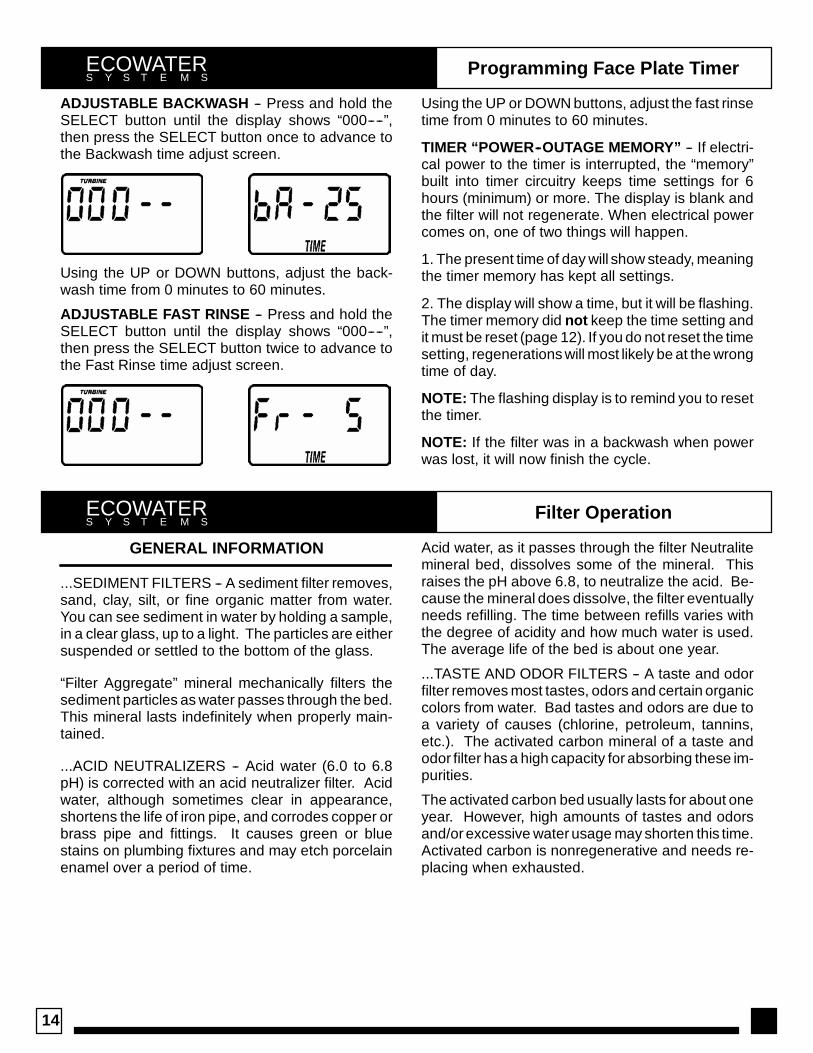
ADJUSTABLE BACKWASH -- Press and hold theSELECT button until the display shows “000----”,then press the SELECT button once to advance tothe Backwash time adjust screen.
Using the UP or DOWN buttons, adjust the back-wash time from 0 minutes to 60 minutes.
ADJUSTABLE FAST RINSE -- Press and hold theSELECT button until the display shows “000----”,then press the SELECT button twice to advance tothe Fast Rinse time adjust screen.
Using the UP or DOWN buttons, adjust the fast rinsetime from 0 minutes to 60 minutes.
TIMER “POWER--OUTAGE MEMORY” -- If electri-cal power to the timer is interrupted, the “memory”built into timer circuitry keeps time settings for 6hours (minimum) or more. The display is blank andthe filter will not regenerate. When electrical powercomes on, one of two things will happen.
1. The present time of day will show steady, meaningthe timer memory has kept all settings.
2. The display will show a time, but it will be flashing.The timer memory did not keep the time setting andit must be reset (page 12). If you do not reset the timesetting, regenerations will most likely be at the wrongtime of day.
NOTE: The flashing display is to remind you to resetthe timer.
NOTE: If the filter was in a backwash when powerwas lost, it will now finish the cycle.
Filter OperationECOWATERS Y S T E M S
GENERAL INFORMATION
...SEDIMENT FILTERS -- A sediment filter removes,sand, clay, silt, or fine organic matter from water.You can see sediment in water by holding a sample,in a clear glass, up to a light. The particles are eithersuspended or settled to the bottom of the glass.
“Filter Aggregate” mineral mechanically filters thesediment particles as water passes through the bed.This mineral lasts indefinitely when properly main-tained.
...ACID NEUTRALIZERS -- Acid water (6.0 to 6.8pH) is corrected with an acid neutralizer filter. Acidwater, although sometimes clear in appearance,shortens the life of iron pipe, and corrodes copper orbrass pipe and fittings. It causes green or bluestains on plumbing fixtures and may etch porcelainenamel over a period of time.
Acid water, as it passes through the filter Neutralitemineral bed, dissolves some of the mineral. Thisraises the pH above 6.8, to neutralize the acid. Be-cause the mineral does dissolve, the filter eventuallyneeds refilling. The time between refills varies withthe degree of acidity and how much water is used.The average life of the bed is about one year.
...TASTE AND ODOR FILTERS -- A taste and odorfilter removes most tastes, odors and certain organiccolors from water. Bad tastes and odors are due toa variety of causes (chlorine, petroleum, tannins,etc.). The activated carbon mineral of a taste andodor filter has a high capacity for absorbing these im-purities.
The activated carbon bed usually lasts for about oneyear. However, high amounts of tastes and odorsand/or excessive water usage may shorten this time.Activated carbon is nonregenerative and needs re-placing when exhausted.

3
15
Filter OperationECOWATERS Y S T E M S
SERVICE, BACKWASH AND FAST RINSE
SERVICE (Figure 23): Unfiltered water enters thevalve inlet port. Internal valve porting routes the wa-ter down and out the top distributor, into the mineraltank. The water is filtered as it passes through themineral bed, then enters the bottom distributor. Fil-tered water flows back into the valve and out thevalve outlet, to the house filtered water pipes.
In time, the filter needs cleaning to remove sedi-ments, dirt, iron, etc., from the mineral bed. Thiscleaning is done in two stages, or cycles, calledbackwash and fast rinse. It is started automaticallyby the timer.
BACKWASH (Figure 24): The timer starts the valvemotor and moves the valve into backwash position.
Water is routed down and out the bottom distributor,up through the mineral bed, and out the top distribu-tor to the drain. The fast flow (controlled by a flowplug in the drain fitting) flushes dirt, sediments, irondeposits, etc. to the drain. The mineral bed is liftedand expanded for maximum cleaning.
FAST RINSE (Figure 25): Valve rotation positionsthe inner discs so water flow enters the mineral tankthrough the top, and exits at the bottom, to the drain.The fast flow of water downward, packs the mineralbed and prepares it for return to service.
The timer energizes the valve motor again to returnthe valve to service.
WATER FLOW PATHS
FIGURE 23
SERVICE CYCLE
POSITIONSWITCH

3
16
Filter OperationECOWATERS Y S T E M S
FIGURE 24
BACKWASH CYCLE
FLOW PLUG
POSITIONSWITCH
FIGURE 25
FAST RINSE CYCLE
POSITIONSWITCH

3
17
Service InformationECOWATERS Y S T E M S
NEUTRALIZING FILTER -- CHECKING THE MIN-ERAL LEVEL IN THE TANK: As explained on page14, the mineral dissolves in the water to neutralizethe acid. How fast is dissolves depends on howmuch water you household uses and the pH of thewater.
Every few months you should measure the mineralbed level in the tank. Always add new mineral beforethe tank is empty. To measure, do the following.
1. Refer to page 13 and initiate the RECHARGENOW feature.
2. When water starts to run from the drain hose, putthe plumbing bypass valve(s) in bypass position,see Figure 20, page 10, TO DEPRESSURIZE THEFILTER.
3. Unplug the transformer at the wall outlet.
4. Remove the controller cover.
5. Disconnect the inlet and outlet copper tubes, seepage 9.
6. Remove the valve assembly from the mineraltank, page 5.
7. Remove the top distributor and four o--ring seals,page 5.
FIGURE 26
SUGGESTED FREEBOARD
ETF2100PF10 38 cm
ETF2100PF12 40.5 cm
8. Use a yard stick or steel tape measure to find thedistance down to the top of the mineral bed, see Fig-ure 26. If 38 cm below the suggested freeboard, addmore neutralite material.
9. Use a funnel to add more mineral, if needed.
10. Flush all mineral from the tank top opening.Then replace the distributor and four o--ring seals,Figure 14, page 5.
11. Do the following steps to return the filter to ser-vice.
-- step 6, page 5
-- step 1b and 1c, page 9
-- step 8, page 10, if hose was disconnected
-- steps 9 through 12, page 11.
NOTE: After electrical power is applied, see page 14if the time display is flashing.
-- initiate RECHARGE NOW feature, see page 13.
TASTE AND ODOR FILTER -- REPLACING THEACTIVATED CARBON MINERAL BED (SEE PAGE14): When the filter no longer removes tastes and/orodors from the water, the activated carbon bed mustbe replaced. To replace the bed:
1. Do steps 1 through 7, above left.
2. Carefully lay the filter tank over. Pull the standpipeand bottom distributor from the mineral bed.
3. Dump the contents of the tank into a suitable con-tainer.
4. Stand the tank upright and replace the bottom dis-tributor and standpipe.
5. Add the required amounts of gravel, filter sand,and activated carbon mineral. See specifications,page 4.
6. Do steps 10 and 11, above.

3
18
Service InformationECOWATERS Y S T E M S
TROUBLESHOOTING
ALWAYS MAKE THESE INITIAL CHECKS FIRST
1. Does the time display show the correct time ofday?
...If display is blank, check power source to the filter.
...If time is flashing, power was off for over two days.The filter resumes normal operation but back-washes occur at the wrong time.
2. Plumbing bypass valve(s) must be in SERVICEposition (see figure 7, page 9). Optional bleedscrewis to be completely closed.
3. The inlet and outlet pipes must connect to the filterinlet and outlet respectively.
4. Is the transformer plugged into a “live” groundedwall outlet, and the power cable fastened securely?
5. The valve drain hose must be free of kinks andsharp bends.
If you do not find the problem after making the initialchecks, do the MANUAL ADVANCE DIAGNOS-TICS.
MANUAL INITIATEDELECTRONICS DIAGNOSTIC
1. To enter diagnostics, press and hold the SELECTkeypad until (000-- --) shows in the display.
The letter (P) and dash or dashes indicate positionswitch operation. The letter shows if the switch isclosed. A dash shows when the switch is open.
SWITCHDISPLAYS VALVE CYCLE STATUS
-- -- valve in service, backwash or fastrinse position
-- P valve rotating from one position toanother
Use the RECHARGE keypad to manually advancethe valve into each cycle and check correct switchoperation.
While in this diagnostic screen, the following infor-mation is available and may be beneficial tor variousreasons. This information is retained by the comput-er from the first time electrical power is applied to theface plate.
...Press the UP keypad to display the number ofdays this face plate has had electrical power ap-plied.
...Press the DOWN keypad to display the number ofregenerations initiated by this face plate since themodel code number was entered.
2. Press the SELECT keypad and hold for 3 secondsuntil the model code appears in the display.
NOTE: For correct filter operation, the model codemust be HPF.
To reset the code, press the UP or DOWN keypadsuntil the correct model code shows in the display.
3. Press the SELECT keypad to return the presenttime display. If the code was changed, make ALL thetimer settings, page 12 and 13.
NOTE: If the face plate is left in a diagnostic display (or a flashing display when setting times or daysto recharge), preset time automatically returns if a button is not pressed within 4 minutes.
3
19
Service InformationECOWATERS Y S T E M S
MANUAL ADVANCE DIAGNOSTIC
Use the following procedures to advance the filtervalve through the regeneration cycles to check op-eration.
Remove the top cover to observe cam and switchoperation during valve rotation.
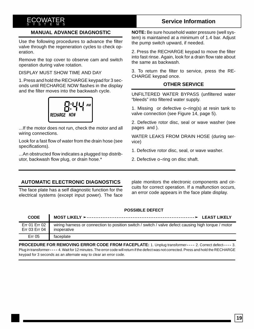
DISPLAY MUST SHOW TIME AND DAY
1. Press and hold the RECHARGE keypad for 3 sec-onds until RECHARGE NOW flashes in the displayand the filter moves into the backwash cycle.
...If the motor does not run, check the motor and allwiring connections.
Look for a fast flow of water from the drain hose (seespecifications).
...An obstructed flow indicates a plugged top distrib-utor, backwash flow plug, or drain hose.*
NOTE: Be sure household water pressure (well sys-tem) is maintained at a minimum of 1.4 bar. Adjustthe pump switch upward, if needed.
2. Press the RECHARGE keypad to move the filterinto fast rinse. Again, look for a drain flow rate aboutthe same as backwash.
3. To return the filter to service, press the RE-CHARGE keypad once.
OTHER SERVICE
UNFILTERED WATER BYPASS (unfiltered water“bleeds” into filtered water supply.
1. Missing or defective o--ring(s) at resin tank tovalve connection (see Figure 14, page 5).
2. Defective rotor disc, seal or wave washer (seepages and ).
WATER LEAKS FROM DRAIN HOSE (during ser-vice)
1. Defective rotor disc, seal, or wave washer.
2. Defective o--ring on disc shaft.
AUTOMATIC ELECTRONIC DIAGNOSTICS
The face plate has a self diagnostic function for theelectrical systems (except input power). The face
plate monitors the electronic components and cir-cuits for correct operation. If a malfunction occurs,an error code appears in the face plate display.
POSSIBLE DEFECT
CODE MOST LIKELY ---------------------------------------------------------------------------------------------- LEAST LIKELY
Err 01 Err 02Err 03 Err 04
wiring harness or connection to position switch / switch / valve defect causing high torque / motorinoperative
Err 05 faceplate
PROCEDURE FOR REMOVING ERROR CODE FROM FACEPLATE: 1. Unplug transformer-------- 2. Correct defect-------- 3.Plug in transformer-------- 4. Wait for 12 minutes. The error code will return if the defect was not corrected. Press and hold the RECHARGEkeypad for 3 seconds as an alternate way to clear an error code.

3
20
Service InformationECOWATERS Y S T E M S
M24V
WIRING SCHEMATIC
BACK OF TIMER
NC
NO
POSITIONSWITCH
24VAC
TRANSFORMER

3
21
Repair PartsECOWATERS Y S T E M S
36
38
37
22
20
21
27
26
28
29303132
33
34
35
24
25
23

3
22
Repair PartsECOWATERS Y S T E M S
KEYNO.
PARTNO. DESCRIPTION
20 ARE001 Transformer, 24V -- 10VA
21 7130767 Wire Harness
22 7218670 Top Cover
23 7260059 Rep’l PWA
24 7210509 Face Plate (order following decal)
-- 7259901 Decal
25 7211173 Face Plate Support
26 7176292 Clamp Section, 2 req’d
27 7088033 Clamp Retainer (Clip), 2 req’d
28 7170296 O--ring, 2--7/8 I.D. x 3--1/4 O.D.
29 7170254 O--ring, 13/16 I.D. x 1--1/16 O.D.
30 7088855 Top Distributor
31 7170270 O--ring, 2--3/4 I.D. x 3 O.D.
32 7105047 Rep’l Distributor, bottom
33 7092202 Resin Tank, 10” dia. x 47”
-- 7113074 Resin Tank, 12” dia. x 54”
34 -- Filtering Minerals ¡
-- 0505647 Filter Aggregate, 1 cu. ft. (28 liters)
-- 3423699 Neutralite, 1/2 cu. ft.(14 liters)
-- 4100700 Activated Carbon, 1 cu. ft. (28 litres)
-- 7175149 Activated Carbon, 50 lbs.(22.7 kg)
35 WSM001 Gravel (order amount needed)
36 7210460 Rim
37 7218646 Shroud, 10” dia. x 47”
-- 7218654 Shroud, 12” dia. x 54”
38 7141205 Tank Base
J 0501783 Filter Sand, 10 lbs. ¡
NOTE: See specifications, page 4, for mineral bed requirements.
¡ Not included with filter.
J Not illustrated.

3
23
Repair PartsECOWATERS Y S T E M S
1
2
3
4
5
6
7
8910
11121314
15
16
171819
20
21
22
23
25 24
28
29
30
31
32
33
22
cross--sectionview
seal
wear--strip
flow plugassembly
assembledview
27
26 36
35
34

3
24
Repair PartsECOWATERS Y S T E M S
KEYNO.
PARTNO. DESCRIPTION
1 7224087 Screw, #8-32 x 1” (2 req.)2 7250622 Motor (incl. 2 ea. of Key No. 1)3 7231393 Motor Plate4 0900857 Screw, #6-20 x 3/8 (3 req.)5 7171250 Bearing6 7219545 Cam and Gear7 7169180 Clip (Drain)8 7172793 Drain Hose Adaptor9 7170288 O-ring, 15/16 x 1--3/16
10 7178189 Flow Plug, 5 gpm-- 7178202 Flow Plug, 7 gpm (12” dia. APF)11 7170327 O-ring, 5/8 x 13/16 J12 7173024 O-ring, 1--1/8 x 1--1/2 J13 7174313 Bearing, Wave Washer14 7185500 Rotor & Disc15 7173032 O-ring, 4--1/2 x 4--7/8 J16 7171179 Rotor Seal J-- 7171331 Wear Strip J
17 7172989 Seal J18 7171187 Plug (Drain Seal)19 7129889 Spring20 7089306 Clip (2 req.)21 7077642 Copper Tube, 1” (2 req.)22 7170262 O--ring, 1--1/8 x 1--3/8 (4 req.)
KEYNO.
PARTNO. DESCRIPTION
23 7171145 Valve Body24 7195482 Seal J25 7170319 O--ring, 1/4 x 3/826 7100940 Plug27 7081201 Retainer28 7175199 Wave Washer29 7171161 Valve Cover30 7172997 Screw, #10 x 2--5/8 (8 req.)31 7145186 Switch32 7140738 Screw, #4-24 x 3/4 (2 req.)33 7214383 Bypass Valve (Includes following
parts)-- 7172882 Stem-- 7173016 O--ring, 1.109 I.D. x 1.387 O.D.
(4)-- 7175238 C--ring
34 7207726 Ground Wire35 7163427 Hose Clamp (2)36 7078240 SupportJ 7185487 Seal Kit (incl. Key Nos. 11, 12,
15, 16, 17 and 24)Optional part.