packet switching in a multiaccess broadcast channel - ucla switching... · the markovian model for...
TRANSCRIPT

IEEE TRANSACTIONS ON COMMUNICATIONS, VOL. COM-~~ , NO. 9, SEPTEMBER 1975 891
REFERENCES [I] E. Hoffmann and D. L. Schillfpg, “Distortion in the frequency
demodulator using feedback, IEEE Trans. Commun., vol.
[2] J. Klapper and J . T. Frankle, Phase-Locked and Frequency- COM-20, pp. 157-165, Apr. 1972.
Feedback Systems. New York and London: Academic Press, 1972.
[3] L. H. Enloe, “The svnthesis of frequency feedback demodu- lators,’’ in Proc. Nut. ”Electronics Conf., vol. 18, 1962, p. 477.
[4] E. Bedrosian and S. 0. Rice, “Distortion and crosstalk of linearly filtered, angle modulated signals,” Proc. IEEE, vol. 56, pp. 2-i4, Jan. 1968:
[5] A. Mircea, “Harmonic distortion and intermodulation noise in linear FM svstems.” Rev. Roum. Sci. T e c h . , Eleckotechn. et Energ., vol. i2, pp. ’359-371, 1967.
[6] A. Mircea and H. Sinnreich, “Distort.ion noise in frequency- dependent nonlinear networks,” Proc. Znst. Elec. Eng. (Lon- don), vol. 116, pp. 1644-1648, Oct. 1969.
[7] I. S. Stojanovid and Z. D. Stojanovid, “Determination of integration limits in calculating distortion noise power,” Proc. Inst. Elec. Eng. (London), vol. 114, pp. 1206-1208, Oct. 1967.
[SI E. Bedrosian and S. 0. Rice, “The output properties of Volterra systems (nonlinear systems with memory) driven by harmonic and Gaussian input,” Proc. IEEE, vol. 59, pp. 1688-1707, Dec. 1971.
[9] C. L. Ruthroff, “Computation of FM distortion in linear net- works for bandlimited periodic signals,” Bell Syst. Tech. J . , V O ~ . 47, ~ p . 1043-1063, July-Aug. 1968.
[IO] L. H. Enloe, “Decreasing the threshold in FM frequency feed-
[11] P. F. Panter, Communication Systems Design. New York:
[12] CCIR, XIIth Plenary Assembly, New Delhi, India, vol. IV,
back,” Proc. IRE, vol. 50, pp. 18-20, Jan. 1962.
McGraw-Hill, 1972, p. 216.
part 1, p. 111, 1970.
Zorka D. Stojanovii was born in Belgrade, Yugoslavia, on February 22, 1935. She received the Dip1.-Eng. degree in communica- tion and electronics engineering and the M.Sc. degree, both from the Faculty of Electrical Engineering, University of Bel- grade, Belgrade, Yugoslavia, in 1958 and 1968, respectively.
From 1958 to the present, she has been with the Department of Communication of t,he Faculty of Electrical Engineering, Uni-
versity of Belgrade, where she taught several courses in Communi- cation Theory and Communication System Design. She published several papers and she was coauthor of two books. She participated also as Project Engineer in several radio links and TV system projects in Yugoslavia.
Packet Switching in a Multiaccess Broadcast Channel: Dynamic Control Procedures
Abstract-In a companion paper [I], the rationale for multiaccess broadcast packet communication using satellite and ground radio channels has been discussed. Analytic tools for the performance evaluation and design of uncontrolled slotted ALOHA systems have been presented. In this paper, a Markovian decision model is formu- lated for the dynamic control of unstable slotted ALOHA systems and optimum decision rules are found. Numerical results on the performance of controlled channels are shown for three specific dynamic channel control procedures. Several practical control schemes are also proposed and their performance compared through simulation. These dynamic control procedures have been found to be not only capable of preventing channel saturation for unstable channels but also capable of achieving a throughput-delay channel performance close to the theoretical optimum.
munication of the IEEE Communications Society for publication Paper approved by the Associate Editor for Computer Com-
without oral presentation. Manuscript received November 21, 1974; revised March 24, 1975. This work was supported in part by the Advanced Research Projects Agency of the Department of Defense under Contract DAHC 15-73-C-0368.
Yorktown Heights, N. Y. 10598. S. S. Lam is with the IBM Thomas J. Watson Research Center,
versity of California, Los Angeles, Calif. 90024. L. Kleinrock is with the Computer Science Department, Uni-
T I. INTRODUCTION
RENDS in the growth of computer-communication networks seem to indicate that the next generation of
networks will be a t least an order of magnitude larger than existing designs. Present implementations, however, are not directly applicable to very large networks. New tech- niques are needed which can provide cost-effective high- speed communications for large populations of (potentially mobile) users scattered over wide geographical areas. Under these circumstances, packet switched satellite and ground radio systems are emerging as attractive solu- tions to the design of computer-communication networks and terminal access networksj respectively [1)-[6]. The rationale for packet switching using satellite and ground radio channels in a multiaccess broadcast mode has been examined in [l].
A multiaccess broadcast packet switching technique which has attracted considerable attention is the slotted ALOHA random access scheme [l>[lO]. This paper is a

892 IEEE TRANSACTIONS ON COMMUNICATIONS, SEPTEMBER 1975
sequel to [I] in which an analytic model and a methodo- logy for the performance evaluation of (uncontrolled) slotted ALOHA channels were developed. Specifically, a theory was proposed in [l] to explain the dynamic and stochastic channel behavior. Stable and unstable channels have been characterized. The trading relations among channel stability, channel throughput, and average packet delay were also shown.
In this paper, we study dynamic control procedures for unstable slotted ALOHA channels. The Markovian model formulated in [l], [SI, [SI for a slotted ALOHA system is first introduced. Assuming that all channel users have exact knowledge of the instantaneous state of the system, three dynamic channel control procedures are described. A general Markovian decision model is next formulated by injecting two classes of control actions into the above model. State transition costs are defined so that the channel performance measures, namely, the stationary channel throughput rate Sout and the stationary average packet delay D, can be expressed in terms of the cost rates of the resulting Markovian decision processes. It is then shown that for the given model an optimal control policy exists which is a stationary policy and which maximizes Sout and minimizes D simultaneously. An efficient computational algorithm for finding the optimal control policy based upon Howard’s policy-iteration method [ll], [l2] is next presented. The three specific control procedures, namely, the input control procedure (ICP), the retransmission control procedure (RCP) , and the input-retransmission control procedure (IRCP) , are then studied in more detail. Both numerical and simulation results are given for the throughput-delay performance of such controlled slotted ALOHA channels. In all cases considered, the optimal con- trol policies were found to be of the control limit type. Next, we consider the fact that the exact instantaneous channel state is not generally known to individual channel users. A scheme is proposed which estimates the channel state and applies the above optimal control policies using this estimate. Another retransmission control procedure which circumvents the state estimation problem is also suggested. These practical control procedures are then tested through simulation and have been found to be capable of achieving a throughput-delay performance close to the theoretical optimum, as well as capable of prevent- ing channel saturation under temporary overload condi- tions.
11. PRELIMINARIES
In this section, we first present the Markovian model formulated in [l], [6], [S] for a slotted ALOHA system. The stability behavior of uncontrolled slotted ALOHA channels is then discussed. Following that, some definitions are given for Markov decision processes. The three specific dynamic channel control procedures are then described. A general formulation of the problem as a Markovian de- cision model is given in Section 111.
A. The Markovian Model for a Slotted ALOHA System
In a slotted ALOHA system, all users transmit packets into channel time slots independently. If two or more packet transmissions overlap in time at the multiaccessed radio receiver, it is assumed that none is received correctly. This event is referred to as a channel collision. We con- sider a slotted ALOHA channel with a user population con- sisting of M users. Each such user can be in one of two states: blocked or thinking.’ In the thinking state, a user generates and transmits a new packet in a time slot with probability U. A packet which had a channel collision and is waiting for retransmission is said to be backlogged. The retransmission delay RD of each backlogged packet is as- sumed to be geometrically distributed, i.e., each back- logged packet retransmits in the current time slot with probability p. Assuming bursty users, we must have p >> cr. From the time a user generates a packet until that packet is successfully received, the user is blocked in the sense that he cannot generate (or accept from his input source) a new packet for transmission.
Let N t be a random variable (called channel backlog) representing the total number of backlogged packets a t time t. The channel input rate a t time t is St = ( M - Nt)a. Assuming M and u to be time-invariant, N t is a Markov process (chain) with stationary transition prob- abilities and serves as the state description for the system. As in [l], [SI, [SI, we assume that p is given by
1 = R + ( K + l ) /2
where R is the number of time slots in a round-trip channel propagation delay and the parameter K corresponds to the uniform retransmission randomization interval in [4].
B. Channel Stability Consider ( N t , S t ) in the two-dimensional (n,S) plane.
The trajectory of ( N 1 , S t ) is constrained to lie on the straight line S = ( M - n) u which we refer to as the chan- nel load line. For a fixed value of K (or p ) , there is an equilibrium contour in the (n,S) plane defined as the locus of points for which the channel input rate S is exactly equal to the expected channel throughput Sout(n,S) in a time slot [l], [SI, [SI. One such contour is illustrated in Fig. 1. Note that within the shaded region enclosed by the equilibrium contour, So,,(n,S) is greater than S; else- where, S exceeds S o u , (n ,S) . Three channel load lines are also shown in Fig. 1 corresponding to the channel user population sizes M , M’, and M“, and an average user think time of 1 / ~ slots. Arrows on the channel load lines point in the direction of “drift” of N t .
A channel load line may intersect (nontangentially) the equilibrium contour one or more times, and we refer to
This model is similar to the one studied by Metcalfe through a steady-state analysis [7]. He has also recognized the need for channel
probability of “ready” packets. control and proposed a method for controlling the transmission

LAM AND KLEINROCK: PACKET SWITCHING IN BROADCAST CHANNEL 893
@STABLE CHANNEL LOAD LINE @UNSTABLE CHANNEL LOAD LINE @OVERLOADED STABLE CHANNEL
LOAD LINE
CHANNEL SATURATION POINT 0 CHANNEL OPERATING POINT
0 UNSTABLE EQUILIBRIUM
” EQUILIBRIUM CONTOUR
“ma,
0
POINT
3m.m
Fig. 1. Stable and unstable channels,
these as equilibrium points denoted by (ne, S,) . An equili- brium point on a load line is said to be a stable equilibrium point if it acts as a “sink” with respect to the drift of N t ; it is said to be an unstable equilibrium. point if it. acts as a “source.” A stable equilibrium point is said to be a channel operating point if ne 5 n,,, as shown in Fig. 1 ; it is said to be a channel saturation point if ne > n,,,. (We shall use (n,,S,) instead of (n,,S,) to distinguish a channel operating point from other equilibrium points.) A channel load line is said to be stable if it has exactly one stable equilibrium point; otherwise, it is said to be unstable. Thus, the load lines labeled 1 and 3 in Fig. 1 are stable by definition; the load line labeled 2 is unstable. In a stable channel, the equilibrium point (ne,&) determines the steady-state throughput-delay performance of the channel over an infinite time horizon. On the other hand, an un- stable channel exhibits “bistable” behavior; the through- put-delay performance given by the channel operating point is achievable only for a finite time period before the channel drifts towards the channel saturation point. When this happens, the channel performance degrades rapidly as the channel throughput rate decreases and the average packet delay increases. The channel load line labeled 3 in Fig. 1 has a channel saturation point as its only stable equilibrium point. It is overloaded in the sense that 64‘‘ is too big for the given u and K . From now on, a stable channel load line will always refer to 1 instead of 3 [l],
In Fig. 1, S,,, represents the maximum possible through- put rate of the slotted ALOHA channel. For the infinite population model, S,,, was shown to be l / e E 0.368
Given a channel load line, suppose Kept is the optimum K which minimizes no and maximizes So at the channel operating point. For this value of K , the channel may be
[SI, [SI.
~31 , 141.
unstable, in which case the optimum channel performance given by (no,S,) is achievable only for a finite time period. To render the channel stable, two obvious solutions are available [l], [SI, [SI: 1) use a larger value for K , and 2) a1.10~ a smaller user population size M . The first solu- tion gives rise to a larger no; the corresponding average packet delay may then be too large to be acceptable [l]. In the second solution, a small M implies that So << S,,, since u << 1 under the assumption of bursty users. This results in a waste of channel capacity. A third solution is the use of dynamic channel control which constitutes the subject matter of this paper.
C. Markov Decision Processes [11]-[13]
Consider the Markov process (chain) N t which is ob- served at time points t = 0,1,2, - - - to be in one of a finite number of states. The set of states S is labeled by the nonnegative integers (O,l ,2 , - - . , M } . Let a be a finite set of possible actions such that corresponding to each ac- tion a a, a set of state transition probabilities { p i j ( a ) } and a set of expected immediate costs { C,(a) } are uniquely specified. We define a policy f to be any rule for choosing actions and 6 to be the class of all policies. The action chosen by a policy a t time t may, for instance, depend on the complete history of the process up to that point.
Suppose the action at is given by the policy f a t time t , which in turn specifies the state transition probabilities and costs at that time. Thus, f determines both the evolu- tion in time of the Markov process N t and the sequence of costs it incurs. For a policy f which generates the following sequence of act,ions in time { a O , d , ( ~ ~ , - - .,at, - } we define the expected cost per unit time for N t which was initially in state i as
1
where the limit always exists, since the costs are assumed to be bounded; the expectation is taken conditioning on the policy f.
An important subclass of all policies is the class of sta- tionary policies 6,. A stationary policy is defined to be one which chooses an action at time t depending only on the state of the process a t time t . Thus, a stationary policy f is a function f ( .) : S+a. A Markov decision process em- ploying a stationary policy f is a Markov process with sta- tionary transition probabilities.
We now state several well-known results for finite-state Markov decision processes employing stationary policies.
Result 1: Given a stationary policy f such that N t is irreducible we have
di
+i(f) = c Tj(f)Cj(f) & B ( f ) , vi = 0,1 , . -* ,M j=O
(3) where { ?rj(f) ) is the unique stationary probability distri- bution of N t such that

894 IEEE TRANSACTIONS ON COMMUNICATIONS, SEPTEMBER 1975
M
r j ( f ) = C r i ( f ) P ; j ( $ ) , J’ = 0,1,.*.,M
Ti(!) 2 0, i = O , l , . - *,ill/ d-0
and M c T i ( ! ) = 1. i=O
g(f) is said to be the cost rate or expected cost per unit time of the process N ‘ using policy f.
Result 6: If every stationary policy gives rise to an ir- reducible Markov chain, then there exists a stationary policy f* which is optimal over the class of all policies such that
g(f*) = min+i(f), V i = 0,1,-.-,M. f f @
Thus, by the above results, we may limit our attention only to the class of stationary policies. We shall present a computational procedure (to be described below) based upon Howard’s policy-iteration method [ll], [la] which evaluates the cost rate g(f) given a stationary policy f and always leads to an optimal stationary policy within a finite number of computational steps.
Within the class of stationary policies, a subclass of policies known as control limit policies can be described as follows for a two-actioh space a. Either the policy specifies the same action for all states in S or there is a critical state ri ( = 0,1,2, - -, or M - 1) such that if the policy specifies one action for states 0 to ri, the other action is specified for states ri + 1 to M . ri is said to be the control limit.
Finally, we assume that at any time t all channel users have perfect knowledge of the instantaneous channel state (perfect channel state information). This assumption is necessary in the mathematical model, but will be relaxed when we consider practical control procedures based upon insights gained from the analysis.
D. Dynamic Control Procedures By a channel control procedure we mean the set of ac-
tions in the action space a. Here we introduce three channel control procedures which will be studied below in more detail. They are special cases of the Markovian deci- sion model in the next section.
The i npu t control procedure ( I C P ) : This control pro- cedure corresponds to.@ = { accept, reject ] { a,r} . Thus, in any channel state, the possible actions are: accept (ac- tion = a ) or reject (action = r ) all new packets that arrive2 in the current time slot.
A new packet is said to arrive in the current time slot only after it has been generated by the channel user (or i t s external source), processed, and ready for transmission over the channel in the cur- rent time slot. In the mathematical model, a rejected arrival is lost and the channel user generates a “new” packet in the next time slot with probability U. In a practical system, this new packet must actually be the previously rejected packet! We shall elaborate upon this interpretation further below.
The retransmission control procedure (RCP) : Under this control procedure, the action space @ = {po ,pc ) {o,c} where p , and p , are said to be the operating and control values of the retransmission probability p . (Through (1) , p , corresponds to KO which optimizes the channel operat- ing point and p , corresponds to Kc which is large enough to render the channel stable [l].) Obviously, we must have p , < p,. Thus, in any channel state the possible actions are: every backlogged packet is retransmitted in the cur- rent time slot with probability p , (action = o) or with probability p , (action = c ) .
The iTlput-retransmission control procedure ( I R C P ) : This control procedure is a combination of ICP and RCP with the action space a = { (accept, p,) , (accept, p , ) , (reject, p,), (reject, p,) } A {ao,ac,ro,rc}. Thus, for ex- ample, when the action rc is taken, both new and back- logged packets are delayed.
In Fig. 2 (a) and (b) , we show channel load lines cor- responding to channels under ICP and RCP, respectively. We find it easier to illustrate both cases with control limit policies. In Fig. 2 (a) , ri is the ICP control limit. When N t 5 +i, the channel input rate is S t = (ill - N t ) a ; when N t > ri, S t = 0. Similarly, suppose +i is the RCP control limit in Fig. 2(b). When N t 5 ri, K = KO, but as soon as N t exceeds +i, K = K, is used. Note that both con- trolled channels are stable in the sense that the channel saturation point as shown in Fig. 1 no longer exists.
111. THE MARKOVIAN DECISION MODEL
In this section, a Markovian decision model is formu- lated which includes as special cases ICP, RCP, and IRCP introduced above. Expected immediate costs are defined so that the fundamental channel performance measures, namely, the stationary channel throughput rate Sout and the stationary average packet delay D, can be expressed in terms of the cost rates of the resulting Markov decision processes. Finally, it will be shown that an optimal sta- tionary policy maximizes ,Sout and minimizes D simul- taneously.
A . The Control Action Space Consider the action space a, = {P1,P2,...,Pm) where
0 5 < P z < - - < Dm 5 1, and the action space a, =
(y1,y2,- - ‘,Yk} where 0 < y1 < * < yk < 1. Let a =
@I X a2 such that each element in is a two-dimensional vector (P,r). As before, the Markov decision process N t has the finite state space S = { 0,1,2, - - - , i l l}. A stationary con- trol policy f maps S into a. Given a stationary control policy f, f(i) = @,y) means that whenever N t = i, each (new) packet arrival is accepted with probability p (and rejected with probability 1 - p) while each backlogged packet is retransmitted with probability y in the tth time slot. Thus, ICP corresponds to the special case @ =
{ 0,l } X { p o ) ; RCP corresponds to the special case @ =
{ 1 } X ( po ,pc} ; IRCP corresponds to the special case =
Suppose N t is in state i and the stationary control policy (0,l l x { P o , P c l .

LAM AND KLEINROCK: PACKET SWITCHING IN BROADCAST CHANNEL
i
(a) (b) Fig. 2. (a) ICP control limit policy example. (b) RCP control
limit policy example.
f ( i ) = (ply), i t is easy to show that the one-step state transition probabilities are given by
I O1 iy ( 1 - 7 ) 1 - pa) M--i,
895
which accounts for the additional delays incurred by re- jected packets. Note that ( M - i) (1 - p)u is the ex- pected number of packets rejected in the tth time slot. d, is the expected cost in units of delay per packet arrival rejected. We shall assume that d, is equal to an average user think time, i.e.,
1 d, = ;. (8)
This assumption is necessitated by our Markovian model formulation in which each thinking user is assumed to transmit a new packet (which may be a previously rejected new packet) with probability u in a time slot. In an actual system, this random delay may be machine-introduced if needed.
j i i - 2
, i = i - l r ( I - Y ) ~ ( M - i )pu( l - f [l - i y ( 1 - y)”l](l - Pu)”~, j = i Pii(f) = (4)
[l - (1 - 7)i](M - i ) p a ( l - Pu)M--i--l, .j = i + 1
for 0 5 i, j 5 M .
B. Cost Rates and Performance Measures
Suppose N t is in state i and f(i) = (p , y ) . We define the expected immediate cost C;(f) to be
C4f) = -Sou&f)
= -[iy(1 - 7)”’(1 - p u ) W
+ (1 - T ) ~ ( M - i )pu( l - Pu)~-”’] (5)
where Sout(i,f) is the expected channel throughput3 in the tth time slot. By (3) the cost rate of N t is
g8(f) = - C Ti(f)Sout (i ,f) . M
i=O
Thus, the stationary channel throughput rate is given by
Sout = - gs(f). ( 6 )
Next, we show how to compute the stationary average packet delay D. Suppose N t is in state i and f(i) = (Ply). For Dl we define the expected immediate cost to be
Ci(f) = i + (11.1 - i) (1 - p)ud, (7)
where the first term i represents a “holding cost” which accounts for the waiting cost of i packets incurred in the tth time slot; the second term represents a “rejection cost”
slot. Expected number of successful packet transmissions in a time
Next, let S = U2=lm& where &,&, - - -,Sm are noninter- secting sets induced by the stationary control policy f such that
f(i) = ( P z , ~ ) if and only if i E SI
where 1 = 1,2, - - -,m and y is any action in az. By (3) , the cost rate of N t is
= N + Xrdr
= i v + N , (9)
where
is the stationary packet rejection rate; N is the average channel backlog size, and f i r is the average number of re- jected packets in the system by Little’s result [14].
Applying Little’s result once more, the average “wasted time” of a packet is

896 IEEE TRANSACTIONS ON COMMUNICATIONS, SEPTEMBER 1975
The average packet delay (in number of time slots) is given by
where R + 1 represents the transmission and channel propagation delays incurred by each successful packet transmission.
Lemma: Given any stationary control policy f : S -+ a,
Proof: From (3) , (7) , and (8) M 'lf
gd(f) = C iri( f) + ( M - i)ri(f) i==O i = O
1 " = M - - ( M - i ) P l U T i ( f ) .
I = I i c S [
Note that Cz, lm zitS[ ( M - i ) p z u r i ( f ) is just the sta- tionary channel input rate and is thus equal to the sta- tionary channel throughput rate Sout = - g8(f). Hence,
Q.E.D. Theorem: For the above Markovian decision model : 1)
there exists a stationary policy f such that
9 d ( j i ) = min Qd (f)
S a ( P ) = min 8 s (f) ;
f f@.
if and only if
f f @ 8
and 2 ) i f f is a stationary policy satisfying the preceding condition, then f ^ minimizes D and at the same time maxi- mizes Sout over the class 6 of all policies.
Proof: 1) This is a direct consequence of the above lemma and Result 2. 2) By (6) and (12), f minimizes D and maximizes Sout over the class of all stationary policies. The generalization to the class 6 of all policies is a conse- quence of Result 2. Q.E.D.
C . Optimum Channel Performance Applying (6) and (13) to substitute for gd(f) and g, (f)
in (12), we have
which relates D as a one-to-one function of Sout given fixed values of R, M , and u. Note that this function is mono- tonically decreasing with SOut.
Assuming a fixed R, we shorn in Fig. 3 a family of curves each of which depicts D as a function of Sout given by (14). The parameters A6 and u, which determine the channel load line, also define a curve in the two-dimensional space of the performance measures D and Sout. We may con- sider a given control procedure as a mathematical operator which maps 6, (the space of all stationary policies) into one such curve. Each f in 6, is mapped into one point on the curve. The range space of the operator must be a proper subset of points on the curve. Otherwise, it is possi- ble that D = R + 1 and Sout = Mu (i.e., no congestion a t all!). The optimization problem thus corresponds to find- ing the extreme points (maximum Sout and minimum D) of this range space. Since the curve under consideration is monotonically decreasing, these extreme points coincide. Thus, the same control policy f must maximize Sout and minimize D simultaneously.
Given a family of channel load lines (e.g., M varying from 0 to 00 a t fixed u or u varying from 0 to 1 a t fixed M ) , each channel control procedure gives rise to an in- feasible region such as shown in Fig. 3. The boundary of this region represents the optimum channel throughput- delay tradeoff under the above constraints.
IV. AN EFFICIENT COMPUTATIONAL ALGORITHhil
Given a channel control procedure and a channel load line, we must determine the optimal control policy and the associated optimum values for SOut and D. Howard's policy-iteration method described in [ll], [ lZ] enables us to find an optimal policy usually in a small number of iterations. The method is composed of two parts: a value- determination operation and a policy-improvement rou- tine. The difficulty now arises in the solution of the fol- lowing ( M + 1) linear simultaneous equations in the value-determination operation for the cost rate g and the "relative values" vi (setting vo = 0) when M is large (say, a few hundred, which is our range of interest).
M
9 + vi = Ci + p i j ~ j , i = 0,1,2, * - , M . (15) i=O
If we take advantage of the fact that the state transition probabilities pij = 0 for j 5 i - 2 in our model, we may solve the above set of equations recursively using the fol- lowing algorithm. The derivation of the algorithm is straightforward and is given in [6].
Algorithm 1 : This algorithm solves for g and {vi) i,lM in the following set of ( M + 1) linear simultaneous equa- tions :
1l4
9 = CO + C pojvj i=1
M
g + C1 + pljvj j=i
M
g + vi = Ci + p i j ~ y , i = 2,3, * . ,M j 4 - 1

LAM AND KLEINROCK: PACKET SWITCHING IN BROADCAST CHANNEL 897
D
R + l
0 %"t
Fig. 3. Optimum performance of a channel control procedure.
where
The algorithm is as follows. Step 1: Define
1 M-1
Step 3: Define
1 M-1
.\f
CO + C Pojtoi j=1
g, = " 1 vi = Uig + wi, i 1 , 2 , . * * , 6 1 .
1 - pojuj j=1
Algorithm 1 has the advantage that the crucial variables bi and cli in the algorithm are computed recursively such that the state transition probabilities pcj can be computed as needed. This eliminates the need for storing the { [ ( M + 1 ) ( M + 2)]/2} + 14 elements in the state transition matrix and virtually eliminates any machine storage constraint on the dimensionality of the optimiza- tion problem. The number of arithmetic operations re- quired is comparable to that of a standard solution method such as Gauss elimination [15].
We present below our computational procedure (PO- LITE) for the Markovian decision model, which combines the policy-iteration method, Algorithm 1, and the above Lemma. Given a channel load line and a dynamic channel control procedure, POLITE finds the optimal control policy and evaluates the optimum channel performance measures.
Algorithm 2 (POLITE) : Step 1 : Given a policy f, apply Algorithm 1 to obtain g
and {ui}i , lM; p i i ( f ) and C i ( f ) are computed when needed in the algorithm.
Step 2: For state i = 0,1, * - - , M define the test quantity
M
Cost(i,a) = C,(a) + Pi j (")" . j=1
Find 6 such that Cost (i ,6) = Cost (i ,a) . If Cost (i,f(i)) = Cost(i,&), then let f(i) = f(i) ; otherwise, let
Step 3: Iff and f are identical, go to Step 4; otherwise,
Step 4: f is an optimal control policy; g = qs(f) or
Step 5: Applying (6) , (12), and (13) , the optimum
j ( i ) = 6.
replace f by f and go to Step 1.
gd( f ) depending on the expected immediate costs C,(a).
performance measures are
souout* = - !Is (S)
V. NUMERICAL RESULTS Numerical results have been obtained for the ICP,
RCP, and IRCP control procedures using POLITE. In this section, we first discuss the optimality of control limit policies. The performance of controlled channels under ICP, RCP, and IRCP is then shown. More specific computational considerations are discussed in [SI, [lo]. A. Control Limit Policies
Consider ICP and RCP. The action space a of both control procedures consists of two actions (a,,a,}. a. is the Step 4: Finally,
898 IEEE TRANSACTIONS ON COMMUNICATIONS, SEPTEMBER 1975
operating action, designed to give near optimum channel throughput-delay performance under equilibrium condi- tions. a, corresponds to "accept" in ICP and p, in RCP. ac is the control action, designed to prevent the channel from drifting into saturation. ac corresponds to "reject" in ICP and p , in RCP.
Our intuition suggests that a good control policy (for either ICP or RCP) must be such that the control action is applied whenever the channel backlog size N 1 exceeds some threshold value to prevent it from drifting away. But as soon as N t decreases below this threshold value, the control action should be replaced by the operating action for optimum performance. This intuition has been confirmed in all our numerical solutions for ICP and RCP. In each case, the optimal control policy given by POLITE is a control limit policy of the following form:
I a,, i 5 ri
a,, i > T i (16)
where ri is said to be the control limit (CL) of the control limit policy f . A rigorous proof of the optimality of the con- trol limit policy remains an open problem. Some diffi- culties in the pursuit of such a proof are discussed in [SI.
B. Performance of Controlled Channels
f ( i ) =
In this section we show the throughput-delay per- formance of controlled slotted ALOHA channels under ICP, RCP, and IRCP. The following numerical constants corresponding to a satellite channel are assumed. Note that a satellite channel is characterized by a large round-trip channel propagation delay R (compared to ground radio). R will be taken to be 12 channel time slots and each time slot is 22.5 ms long, giving 44.4 slots/s. The above figures are computed from the assumptions of a 50 kbit/s satellite voice channel, 1125 bits/packet, and a round-trip channel propagation time of 0.27 s for all channel users. The dura- tion of a channel time slot is assumed to be the same as a packet transmission time. From our discussion in the previous section, all control policies considered below for ICP and RCP are of the CL type.
Choosing KO: Given an unstable channel, the through- put-delay performance at the operating point ( n,,S,) is what we strive to achieve through dynamic channel con- trol. Thus, it is essential to choose the operating value of K to be Kopt or some KO which yields an operating point close to the optimum. For the numerical constants given above, K = 10 is an excellent choice and will be used throughout this paper as the operating value KO [l], [SI.
Xpecifying a channel load line: The channel load line is a straight line uniquely specified by its intercept on the vertical axis, M , and its slope - l /u . Alternatively, it may be specified by M and the operating point (no,&',) on the equilibrium contour (instead of u) . Thus, different load lines specified by the same channel operating point can be compared by showing how well they approach the throughput-delay performance at the operating point.
150 F KO- 10
O ' " ' " ~ . . . ~ . . . ~ ~ ~ . . . J
KC
0 50 100 150 200
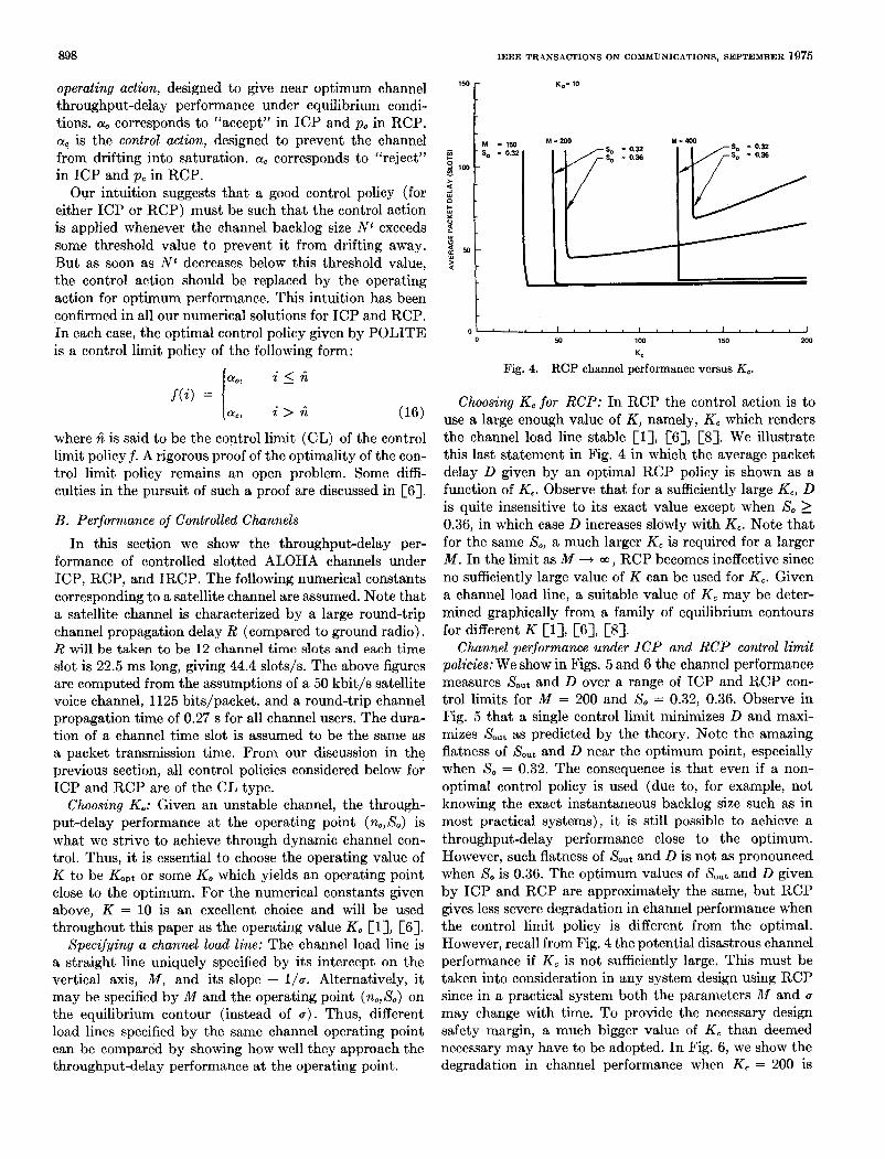
Fig. 4. RCP channel performance versus Kc.
Choosing Kc for RCP: In RCP the control action is to use a large enough value of K , namely, K, which renders the channel load line stable [l], [SI, [SI. We illustrate this last statement in Fig. 4 in which the average packet delay D given by an optimal RCP policy is shown as a function of Kc. Observe that for a sufficiently large Kc, D is quite insensitive to its exact value except when So 2 0.36, in which case D increases slowly with Kc. Note that for the same So, a much larger Kc is required for a larger M . In the limit as M + 00, RCP becomes ineffective since no sufficiently large value of K can be used for Kc. Given a channel load line, a suitable value of K c may be deter- mined graphically from a family of equilibrium contours for different K [l], [SI, [SI.
Channel performance under ICP and RCP control l imit policies: We show in Figs. 5 and 6 the channel performance measures Sout and D over a range of ICP and RCP con- trol limits for M = 200 and So = 0.32, 0.36. Observe in Fig. 5 that a single control limit minimizes D and maxi- mizes Sout as predicted by the theory. Note the amazing flatness of Sout and D near the optimum point, especially when So = 0.32. The consequence is that even if a non- optimal control policy is used (due to, for example, not knowing the exact instantaneous backlog size such as in most practical systems), it is still possible to achieve a throughputdelay performance close to the optimum. However, such flatness of Sout and D is not as pronounced when X , is 0.36. The optimum values of Sout and D given by ICP and RCP are approximately the same, but RCP gives less severe degradation in channel performance when the control limit policy is different from the optimal. However, recall from Fig. 4 the potential disastrous channel performance if Kc is not sufficiently large. This must be taken into consideration in any system design using RCP since in a practical system both the parameters 2cf and u may change with time. To provide the necessary design safety margin, a much bigger value of Kc than deemed necessary may have to be adopted. In Fig. 6, we show the degradation in channel performance when K c = 200 is

LAM AND KLEINROCK: PACKET SWITCHING IN BROADCAST CHANNEL 899
I O.!
0.4
0.:
0.;
0:
w
up
0.01
500 ,- 400 -
300 -
200 -
- v) + s 4 2 > 100 - w 0
k 70- Y
a sl
d 50 -
w 40 > -
a 30 -
20 - M = 200 K = 10
0 SIMULATION 1 MINIMUM I MAXIMUM
10 I I I I I I I 0 10 20 30 40 50 60
INPUT CONTROL LIMIT
Fig. 5. Channel performance versus ICP control limit for M = 200.
used instead of Kc = 60. On the other hand, M has rela- tively little effect on the optimal ICP control limit as shown in Fig. 7 (a). Thus, even if M fluctuates in time in a real system, the same ICP control limit policy is still near optimal. Of course, the optimum channel performance must deteriorate as M increases as shown in Fig. 7 (b) . In the same figure, the optimum D given by ICP and RCP are compared. RCP is found to be slightly better than ICP. However, as M becomes large, Kc must also be large, in which case the trend indicates that ICP is superior to RCP.
In Figs. 5 and 6, we have also indicated simulation re- sults for throughput and delay. In these simulations, channel control policies are applied assuming that the exact instantaneous channel backlog size N t is known to all channel users. However, contrary to the Markovian model, each collided packet is assumed to suffer the more realistic fixed delay of R slots and its retransmission ran- domized uniformly over the next K slots [4]. The Marko- vian model is idealized since R is assumed to be zero while each backlogged packet retransmits in a time slot with probability p . (In both cases, the same average retransmis- sion delay was used.) This excellent agreement between simulation and analytic results presented here demon- strates the usefulness of the Markovian model for a slotted ALOHA system.
Optimum throughput-delay tradeoffs: Optimum through- put-delay tradeoffs a t fixed M are shown in Fig. S for ICP. Note that Sout is maximized and D minimized by the opti- mal ICP control limit ri = 22 for a specific channel load
0.5
0.4
0.3
0.2
0.1
w
up
0.01
500 r
400 c / -S0"t
OPTIMUM
10 0 10 20 30 40 50 60
RETRANSMISSION CONTROL LIMIT
Fig. 6. Channel performance versus RCP control limit for M = 200.
25 r s,=0.32
0 RCP
10 I I I
(a ) 0 100 200 300
lh4 400
r
- ICP - 0- RCP
I I I 0 100 200 300 400
(b)
I t 4
Fig. 7. ICP and RCP channel performance versus M.

900 IEEE TRANSACTIONS ON COMMUNICATIONS, SEPTEMBER 1975
INFINITE POPULATION MODEL
10 I I I .1 .2 .3 0.37
S0"t
Fig. 8. ICP optimum throughput-delay tradeoffs at fixed M .
line. Note how close the ICP throughput-delay tradeoff curves are to the optimum envelope obtained for the in- finite population model in [4]. In fact, the M = 50 trade- off curve lies a little below the optimum envelope. This is to be expected since M = 50 actually gives rise to a stable channel, in which case the throughput-delay performance at the optinlum operating point is achieved.
In Fig. 9, optimum throughput-delay tradeoffs a t fixed values of u for RCP are shown. ( l / u is the average think time of a channel user.) In this case, increasing Sout cor- responds to increasing &I. Note that the channel per- formance improves as the packet generation probability u increases, since this implies that for the same Saut, the number of channel users is smaller and these users are also less "bursty."
IRCP channel performance: Recall that the ICP and RCP action spaces are both subspaces of the IRCP action space. Therefore, the channel performance given by IRCP must be better or a t least as good as that given by ICP or RCP. In Table I, we compare these three control pro- cedures for the four channel load lines involving M = 200, 400 and (n,,X,) = (4,0.32), (7,0.36). Note that in every instance, IRCP gives the best performance. We also ob- served that the optimal control policy for IRCP is of the form
i ao, 0 5 i 5 ril
f(i) = ac, ril < i 5 6% (17)
rc, r i z < i which is uniquely specified by (hl,hz). Also, hl is either equal or very close to the optimal RCP control limit in
100 - - 90
80 - 0 - -
- d 70
5 60
50 - -
-1
t 9 Y o 40 - w 0
d 30- w > a
20 -
15
l /o = 30 SEC K c = 200
l/o = 20 SEC K c = 130
l /o = 10 SEC K c = 60
POPULATION MODEL
10 I I I 1 0.1 0.2 0.3 0.37
S0"t
Fig. 9. RCP optimum throughpubdelay tradeoffs at fixed u.
TABLE I COMPARISON OF ICP, RCP, AND IRCP
14 = 200
S = 0.32
(K = 60)
R
(18,56) IRCP ( f i l , A 2 )
18 RCP R
22 ICP
ICP 0.31778
SO"t 0.31817
IRCP 0.31817
ICP
29.085 RCP D
29.857
IRCP 29.085
M = 200
S = 0.36
(Kc = 60)
18
17
(17.43)
0.34925
0.35217
0.35213
49.552.
44.802
44.712
M = 400
S = 0.32
IK = 1501
22 23
(23,116)
0.31807
0.31844
0.31844
33.096
31.608
31.608
M = 400
S = 0.36
(Kc = 150)
18
22
(23.91)
0.34846
0.34715
0.34847
69.237
73.588
69.215
each case and the use of r i z brings about only minor im- provement in the channel performance except in the case of M = 400 and So = 0.36.
VI. PRACTICAL CONTROL SCHEMES The optimum throughput-delay channel performance
given in the last section is achievable over an infinite time horizon if the channel users have exact knowledge of the channel state at any time. In a practical system, the chan- nel users often have no means of communication among themselves other than the multiaccess broadcast channel itself. Each channel user may individually estimate the channel state by observing the (broadcasted) outcome in each channel slot. However, whatever channel state infor- mation available to the channel users is at least as old as one round-trip propagation delay ( R ) which may introduce
LAM AND KLEINROCK: PACKET SWITCHING IN BROADCAST CHANNEL 901
additional errors in the users’ estimates if R is large (such as in a satellite channel). Thus, the control action applied based upon an estimate of the channel state may not 9Fces- sarily be the optimal one at that time, which will then lead to some degradation in channel performance.
Below we first give a heuristic scheme for estimating the channel state assuming that the history (i.e., empty slots, successful transmissions or collisions) of the channel is available to all channel users. The optimal ICP, RCP, and IRCP control policies may be applied based upon this estimate. A heuristic control procedure is next proposed which circumvents the state estimation problem. These control procedures are then examined through simulation and compared with the theoretical optimum throughput- delay results in the previous section. The ability of these control procedures to handle time-varying inputs (with pulses) is also examined.
A. Channel Control-Estimation Algorithms
The channel trajic in a time slot is defined to be the number of packet transmissions (both new and previously collided packets) by all users in that time slot. Our heuris- tic scheme for estimating the channel state is based upon the observation that the channel traffic in a time slot is approximately Poisson distributed. (See [6, ch. 4 and Appendix A].) Algorithms which implement channel control procedures using the Poisson channel traffic esti- mate will be referred to as control-estimation (CONTEST) algorithms.
We illustrate below a procedure for implementing RCP. Similar algorithms for implementing ICP and IRCP are given in [SI, [9], [lo]. Let ri be the RCP control limit. Define
Go = rip, + ( M - ri). (18)
6, = rip, + ( M - r i )a. (19)
Go and 6, are thus the channel traffic rates when the chan- nel backlog size is ri packets with K equal to KO and Kc, respectively. Assuming that the channel traffic is Poisson distributed, we define the following critical values (cor- responding to the probability of zero channel traffic in a time slot) :
fo = exp [ -Go] ( 20)
and
f c = exp [-G,]. (21)
Since K , > KO we must have
fo < fc.
Suppose each channel user keeps track of the channel history (delayed by one round-trip propagation time) within a window frame of W slots. Let ft be the fraction of empty slots within the history window for the tth time slot. J t will closely approximate the probability of zero channel traffic in the tth time slot provided that 1) the channel traffic probability distribution does not change appreciably in ( W + R ) time slots, 2) that W >> 1, and
3) that the Poisson traffic assumption holds. We give the following CONTEST algorithm to be adopted by each channel user. dt denotes the control decision at time t.
Algorithm 3 ( R C P - C O N T E S T ) : This algorithm gen- erates the decision d t = K,,K, a t each time point based upon the channel state estimate 7 and the RCP control limit r i . Start at Step 1 or Step 4.
Step 1:
t t t + l
dt = KO.
Step W: If Jt < fa, go to Step 4. Step 3: Go to Step 1. Step 4:
t+--t+l
dt = Kc.
Step 5: Iff8 > f,, go to Step 1. Step 6: Go to Step 4.
The channel history window: The size W of the channel history window kept by each channel user is very impor- tant for successful channel state estimation. If W is too large, we may lose information on the dynamic behavior of the channel such that the necessary actions are taken too late. If W is too small, we may get large errors in approx- imating the probability of zero channel traffic by the frac- tion of empty slots in the history window. A good initial estimate is that W should be bigger than R and of the same order of magnitude. Below we compare simulation results on channel performance for different values of W .
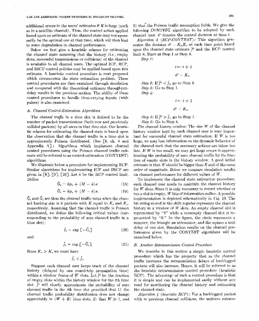
To implement the channel state estimation procedure, each channel user needs to maintain the channel history for W slots. Since it is only necessary to record whether or not a slot is empty, W bits of information suffice. A possible implementation is depicted schematically in Fig. 10. The bit string stored in the shift register represents the channel history in a window of W slots. An empty channel slot is represented by “1” while a nonempty channel slot is re- presented by “0.” In the figure, the circle represents a summer, the triangle an attenuator, and the square a unit delay of one slot. Simulation results on the channel per- formance given by the CONTEST algorithms will be examined below.
B. Another Retransmission Control Procedure We describe in this section a simplc heuristic control
procedure which has the property that as the channel traffic increases the retransmission delays of backlogged packets will also increase. Hence, it will be referred to as the heuristic retransmission control procedure (heuristic RCP) . The advantagn of such a control procedure is that it is simple and can be implemented easily without any need for monitoring the channel history and estimating the channel state.
Algorithm 4 (heur is t ic RCP) : For a backlogged packet with m previous channel collisions, the uniform retrans-

902 IEEE TRANSACTIONS ON COMMUNICATIONS, SEPTEMBER 1975
01111 ~ 0 ~ 1 ~ 0 ~ 0 ~ 0 ~ 1 CHANNEL OBSERVATION ~ ~ ~ , ~ ~ E G I S T E R O O R 1
U UNIT DELAY
Fig. 10. Determination of fc.
n&sion randomization4 interval is taken to be K = K , where K , is a monotone nondecreasing function in m.
When the channel traffic increases, the probability of channel collision increases. A s a result, the "effective" value of K increases. If K, is a steep enough function in nr, we see that channel saturation.wil1 be prevented.
C . Sindatioa Results We summarize, in Tables I1 and 111, throughput-delay
results for the channel load lines specified by (?zo,So) = (4,0.32) and flC = 300, 400. In both cases, we assume that KO = 10 and K c = GO. Included in these tables are 1) optimum POLITE results for ICP, RCP, and IIZCP, 2 ) simulation results for ICP and RCP using optimal control policies and under the assumption of perfect channel state information, 3) simulation results for the CONTEST algorithms using ICP and RCP optimal control policies, and 4) simulation results for heuristic RCP. The duration of each simulation run was taken to be 30 000 time slots. IRCP was not tested by simulation since the optimal value of ri, is in all cases so large that within the simulation dura- tion, the channel state N t (almost surely) will not exceed it; the control procedure beconxs effectively RCP speci- fied by GI.
The ICP-CONTEST algorithm was tested with channel history window sizes of 30, 40, 60, and SO time slots. We see from Tables I1 and 111 that W = 40 appears to give the best throughput-delay results. Note that for R = 12 and K = 10, W = 40 is approximately twice R + K.
The RCP-CONTEST algorithm was also tested with various values of W . In this case, K takes on two values, KO = 10 and Kc = 60. Thcre is no clear-cut optinlal W . It appears that W = 60 is a good choice. There is no signi- ficant, degradation in channel performance (from the opti- mum) given by the CONTEST algorithms and heuristic RCP. The CONTEST algorithms, however, seen1 to have an edge over heuristic RCP. The excellent performance of the CONTEST algorithms can be attributed to the flatness of Sout and D near the optimum as a function of the control limit (see Figs. 5 and 6) . We found that this flatness property is less pronounced for channel load lines with a large value of So or M , such as So = 0.36 or M = 400. This explains the more significant degradation in channel performance given by the CONTEST algorithms shown in Table 111 for A.ir = 400 than in Table I1 for M = 200.
For an uncontrolled slotted ALOHA channel, i t is shown in [6] that a channel input rate of 0.8 packet/
function i n 'm. Or, equivalently, p = p , where pm is a monotone nonincreasing
TABLE I1 THROUGHPUT-DELAY RESULTS OF A CONTROLLED CHANNEL
( M = 200, So = 0.32)
CONTROL SCBEME c -out
D
ICP (POLITE) 0.3178 29.9
RCP (POLITE) 0.3182 29.1
IRCP (POLITE) 0.3182 29.1
ICP (Simulation) 0.315 33.4
RCP (Simulation) 0.318 28.8
ICP-CONTEST W = 20
ICP-CONTEST W = 40
ICP-CONTEST W = 60
ICP-CONTEST W = 80
RCP-CONTEST W = 20
RCP-CONTEST W = 40
RCP-CONTEST W = 60
RCP-CONTEST V7 = 80
0.314
0.315
0.317
0.318
0.315
0.322
0.319
0.317
40.9
30.5
32.4
35.8
33.1
33.3
32.1
32.5
K = 10 0.316 33.7
{Kl = 60 "22 0.315 34.6 Heuristic RCP
("1 = lo 0.310 35.4
0.316 34.6
TABLE I11 THROUGHPUT-DELAY RESULTS OF A CONTROLLED CHANNEL
( M = 400, So = 0.32)
CONTROL SCHEME Sout
D
ICP (POLITE) 0.3181 33.1
RCP (POLITE) 0.3184 31.6
IRCP (POLITE) 0.3184 31.6
ICP (Simulation) 0.315 31.4
RCP (Simulation) 0.317 31.0
ICP-CONTEST W = 20 0.315 43.3
ICP-CONTEST M = 40 0.314 34.7
ICP-CONTEST W = 60 0.312 53.2
ICP-CONTEST W = 80 0.316 39.1
RCP-CONTEST W = 20 0.313 41.1
RCP-CONTEST W = 40 0.319 43.4
RCP-CONTEST W = 60 0.318 38.8
RCP-CONTEST W = 80 0.317 40.1
RCP-CONTEST W = 100 0.314 35.7
RCP-CONTEST W = 120 0.319 47.1
K = 10 0.316 45.2
Heurlstic RCP { : K = 150 m22 0.316 44.8
0.312 42.0
0.311 43.1

I LAM AND KLEINROCK: PACKET SWITCHING IN BROADCAST CHANNEL
TABLE IV SIMULATION RUN FOR IRCP-CONTEST SUBJECT TO A CHANNEL
INPUT PULSE INPUT PARAMETERS:
NUMBER OF TERMINALS M = 400, PROPAGATIOtI DELAY R = 12 FOR THE TIME PERIOD 1-1000. INPUT RATE Mu = 0.3232 FOR THE TIME PERIOD 1001-1200, INPUT RATE L40 = 1.0 FOR THE TIME PERIOD 1201-6000, INPUT FATE Mu = 0.3232
KO = 10, KC = 150, WINDOW S I Z E W = 60 RETRANSMISSION CONTROL LIMIT = 23, INPUT CONTROL LIMIT = 116
AVERAGE VALUES I N 200 TIME SLOT PERIODS:
903
1 - 200 0.230 0 201 - 400 0.325
0.625 30.2 0.100
5.5 34.0 0
401 - 600 0.285 0.450 0 6.9
601 - 800 23.6
0.235 2.8
0.625 31.7 0 801 - 1000 5.3
0.325 0.850 42.5 0 1001 - 1200 3.3
0.205 1201 - 1400 2.345
0.345 524.3
1.330 389.6 50.0 75.2
43 13
1401 - 1600 0.355 0.880 188.1 51.5 0 1601 - 1800 0.375 0.735 179.3 0 1801 - 2000 0.225 1.295 297.8 33.7 5
34.9
2001 - 2200 0.325 1.005 530.1 35.3 2201 - 2400 0.380 0.905 121.3 0
21
2401 - 2600 0.305 0.485 27.6 16.7
0 2601 - 2800 3.1
0.290 0.430 20.8 2.3 0 2801 - 3000 0.345 0 3001 - 3200 0.300
0.745 0.455
35.3 7.2 0
3201 - 3400 17.6
0.280 0.615 28.4 5.6 0 2.4
3601 - 3800 3401 - 3600 0.330
0.330 3801 - 4000 0.300 4001 - 4200 0.315 4201 - 4400 0.335 4401 - 4600 0.300 4601 - 4800 0.280 4801 - 5000 0,285 5001 - 5200 0.330 5201 - 5400 0.335 .~
5601 - 5800 5401 - 5600 0.335 5801 - 6000
0.275 0.285
0.810 0.655 30.6 5.6 0
37.9 7.9 0
0.390 0 0.615
19.3 29.2
1.7 5.1 0
0.600 24.5 4.5 0 0.450 24.3 0 0.480 25.2 3.7 0
2.6
0.585 32.0 0 0.570
5.3 26.4 4.3 0
0.550 23.6 3.7 0 0.640 28.8 0 0.410 21.5 2.4 0
5.2
0.445 22.3 2.7 0
slot sustained for 100 time slots is enough to cripple the channel indefinitely. In Tables IV and V, we show by simulations that under similar but more severe pulse over- load circumstances both the IRCP-CONTEST algorithm and heuristic RCP prevented the channel from going into saturation. In these simulations, the normal channel load line was given by M = 400 and (no,So) = (4,0.32) both before and after the pulse. During a period of 200 slots (namely. the time period 1000-1200 shown in the tables) the packet generation probability Q was increased such that Mu = 1 packet/slot. Observe that both algorithms handled the sudden influx of new packets with ease. In both cases, the channel throughput, instead of vanishing to zero as in an uncontrolled channel, maintained a t a high rate and within less than 3000 slots, the channel returned to almost normal operation.
D. Discussions of Results In an actual system, the channel user population and
their transmission requirements will typically fluctuate with time. We must emphasize the fact that the control algorithms considered have been designed to control statis- tical channel fluctuations under the assumption of a sta- tionary channel input. Although we showed that they can temporarily handle very high channel input rates, addi- tional control mechanisms should be designed into the system to make sure that channel overload conditions do not prevail for long periods of time (e.g., by limiting the maximum number of users who can “sign-on” and become active channel users).
We showed earlier that IRCP gives a channel perfor-
TABLE V SIMULATION RUN FOR HEURISTIC RCP SUBJECT TO A CHANNEL
INPUT PULSE INPUT PARAMETERS:
NUMBER OF TERMINALS M = 400, PROPAGATION DELAY R = 12 FOR THE TIME PERIOD 1-1000. INPUT RATE MLT = 0.3232 FOR THE TIME PERIOD 1001-1200. INPUT FATE Ma = 1.0 FOR THE TIME PERIOD 1201-6000, INPUT FATE Mo = 0.3232 K = 10 K = 150 (m 2 2 )
AVERAGE VALUES I N 200 TIME S W T PERIODS:
T i m e P e r i o d T h r o u g h p u t __ T r a f f i c rate ra te
Average Backlog - -
1 - 200 0.285 0.395 19.8 0.320 0.330 16.3 0.255 0.425 22.8
201 - 400 401 - 600
2.1 1.2 2.8
601 - 800 801 - 1000 26.1 4.0
28.5 1001 - 1200 0.230 34.1 68.8
5.7
1201 - 1400 1401 - 1600 141.3 112.6
273.1 91.8
0.290 0.475 0.325 0.570
2.395 1.695 1.500
0.285 0.310
1601 - 1800 0.375 1.415 1801 - 2000 0.280 1.110 224.6 53.1
68.5
2001 - 2200 0.360 1.240 257.3 48.8
288.6
2201 - 2400 0.355 0.925 193.9 31.3 2401 - 2600 0.385 0.655 2601 - 2800 0.320 2801 - 3000 0.280
122.8 0.565 68.0 0.420 39.3
15.2 8.8 5.6
3001 - 3200 0.295 0.495 31.6 6.3 3201 - 3400 0.265 0.680 3401 - 3600 0.350 37.0 13.3 0.750
11.7 45.0
3601 - 3800 0.310 3801 - 4000 4001 - 4200 0.330 4201 - 4400 0.325 4401 - 4600
0.465 0.275 0.520
65.2 8.2 33.6 7.7
0.480 34.6 0.615
5.2 29.5 7.5
0.310 0.525 38.6 1.6 4601 - 4800 0.260 4801 - 5000 5001 - 5200
0.705 0.375 0.720 0.350 0.635
44.2 63.5 41.7
15.3 11.1 9.0
5201 - 5400 0.285 0.475 23.3 6.6 5401 - 5600 0.315 5601 - 5800 5801 - 6000
0.510 0.290 0.425 0.305 0.490
36.4 24.1 28.7
4.3 4.1 4.7
mance at least as good as ICP and RCP. Comparing TRCP- CONTEST and heuristic RCP, we see that the latter is easier to implement. However, under a normal load (say So 5 0.32), IRCP-CONTEST is superior to heuristic RCP. This is because heuristic RCP introduces longer delays to collided packets even when these packets are merely unlucky in light channel traffic. On the other hand, with IRCP, control actions are not exerted until the chan- nel traffic exceeds certain “dangerous” levels.
VII. CONCLUSIONS
In this paper, a Markovian decision model has been formulated for the dynamic control of slotted ALOHA random access channels. It is shown that optimal station- ary policies exist. Furthermore, an optimal stationary con- trol policy maximizes the stationary channel throughput rate and minimizes the average packet delay simultane- ously. An efficient computational algorithm (POLITE) is developed which utilizes Howard’s policy-iteration method and is capable of solving for an optimal stationary policy in a small number of computational steps. Numerical results for the control procedures ICP, RCP, and IRCP indicate that optimal control policies are of the control limit type, but a rigorous mathematical proof of this result in general remains an open problem. Throughput- delay tradeoffs given by optimal control policies are also presented. These throughput-delay results are very close to the optimum performance envelope in [4] and are achievable over an infinite time horizon for originally unstable channels. Since in a practical system the exact

904 IEEE TRANSACTIONS ON COMIMUNICATIONS, SEPTEMBER 1975
instantaneous channel state is not known but nlust be [61 s. s. Lam, “Packet switching in a multi-access broadcast
estimated, channel control-estimation (CONTEST) algo- channel with application to satellite communication in a com- puter network,” Ph.D. dissert,at,ion, Comput. Sci. Dep., Univ.
rithms based upon a Poisson channel traffic & h a t e are [71 R. M. Metcalfe, “packet comm,~nication,~~ Massachusetts of California, Los Angeles, Mar. 1974.
proposed. A heuristic retransmission control algorithm is Inst. Technol., Cambridge, Project MAC Tech. Rep. TR-114,
algorithms are capable of achieving a channel throughput- in a random multi-access broadcast channel,” in Proc. 7th
well as capable of preventing channel saturation under [9] S. S. Lam and rJ. Kleinrock, “Dynamic control schemes for a temporary overload conditions. packet switched multi-access broadcast channel,” in 1975 Nut.
The problem of unstable behavior is very real in random Comput. Conf., A F I P S Conf. Proc., vol. 44. Montvale, N. J.: AFIPS Press, 1975, pp. 143-153.
systems (e.g., ALOHA [ 2 ] , slottecl ALOHA, carrier [lo] ---, “Packet switching in a multi-access broadcast channel:
sense multiaccess [16], etc.) . To guarantee an acceptable Dynamic control procedures,” T. J. Watson Res. Center, IBM Corp.. Yorktown Heights. N. Y.. Res. Reo. RC-5062. Oct..
suggested‘ Simulations indicate that these [8] L. KleiIlrock and S. S. Lam, “On stability of packet switching Dec. 1973.
delay performance close to the theoretical optimum, as Hawaii Int. C0n.f. SYSl. SCi. (Special Subconf. ComPut. Nets), Univ. of Hawaii, Honolulu, Jan. 1974.
level of channel performance for such systems, some form of dynamic channel control is a must. The probabilistic model and dynamic channel control schemes introduced herein for a slotted ALOHA channel can probably be ex- tended to study stability and dynamic control problems of other random access systems.
REFERENCES [l] L. Kleinrock and S. S. Lam, “Packet switching in a multiaccess
broadcast channel: Performance evaluation,” IEEE Trans .
[2] N. Abramson, “The ALOHA System-Another alternative for Commun., vol. COM-23, pp. 410-423, Apr. 1975.
computer communications,” in 1970 Fall Joint Comput. Conf., A F I P S Conf. Proc., vol. 37. Montvale, N. J.: AFIPS Press,
[3] -, “Packet switching with satellites,” in 1973 Nut. Comput. Conf . , AFIPS Conf. Proc., vol. 42. Montvale, N. J.: AFIPS Press, 1973, pp. 695-702.
[4] L. Kleinrock and S. S. Lam, “Packetrswitching in a slotted satellite channel,” in 1973 Nut. Comput. Conf., AFZPS Conf. Proc., vol. 42. Montvale, N. J.: AFIPS Press, 1973, pp. 7nx-71 n
1970, pp. 281-285.
1974. ’ [ l l ] R. Howard, Dynamic Programming and Markov Processes.
[12] -, Dynamic Probabilistic Systems, Vol. 1 : Markov Models, Cambridge, Mass.: M.I.T. Press, 1960.
Wiley, 1971. Vol. 8: Semi-Markov and Decision Processes. New York:
[13] S. M. Ross, Applied Probability Models with Optimization Applications. San Francisco: Holden-Day, 1970.
[14] L. Kleinrock, Queueing Systems, Vol. I , Theory. New York: Wiley Interscience, 197.5, p. 17.
[15] E. J. Craig, Laplace and Fourier Transforms for Electrical Engineers. New York: Holt, Rinehart and Winston, 1964.
[16] L. Kleinrock and F. A. Tobagi, “Carrier sense multiple access for packet switched radio channels,” in Proc. Int. Conf. Com- mun., Minneapolis, Minn., 1974.
LI I
* Simon S. Lam (S’69-M’74), for a photograph and biography see page 423 of the April 1975 issue of this TRANSACTIONS.
* . V V . - . I . [5] L. G. Roberts, “Dynamic allocation of satellite capacity
through packet reservation,” in 1978 Nut. Comput. Conf., A F I P S Conf. Proc., vol. 42. Montvale, N. 3.: AFIPS Press, Leonard Kleinrock (S’55-M’64-SM’7l-FJ73), for a photograph and 1973, pp. 711-716. biography see page 423 of the April 1975 issue of this TRANSACTIONS.