part 2: particular design and performance specifications · particular design and performance...
TRANSCRIPT

Contract for the Civil Works of LRT Line 2 BID DOCUMENTS East (Masinag) Extension Project Section VI. Procuring Entity’s Requirements Package 2 – Design and Build of Stations Part 2: Particular Design and Performance Specifications
Part 2: Particular Design and Performance
Specifications

Contract for the Civil Works of LRT Line 2 VI – 39 BID DOCUMENTS East (Masinag) Extension Project Section VI. Procuring Entity’s Requirements Package 2 – Design and Build of Stations Part 2: Particular Design and Performance Specifications
PARTICULAR DESIGN AND PERFORMANCE SPECIFICATIONS FOR
EMERALD AND MASINAG STATIONS
TABLE OF CONTENTS
Page
1. GENERAL DESIGN REQUIREMENTS .............................................................. VI-41
1.1 Introduction ........................................................................................................ VI-41
1.2 Units ................................................................................................................... VI-42
1.3 Survey and Setting Out ...................................................................................... VI-42
1.4 Design Requirements ......................................................................................... VI-42
1.5 Materials Requirements ...................................................................................... VI-44
1.6 Special Design Considerations ........................................................................... VI-46
1.7 Vehicular and Pedestrian Traffic Management .................................................. VI -47
1.8 Railway Traffic Management ............................................................................. VI -48
1.9 Durability Assurance .......................................................................................... VI -48
2. BUILDING STRUCTURAL DESIGN REQUIREMENTS ..................................... VI-50
2.1 General ............................................................................................................. VI -50
2.2 Standard and Codes of Practice .......................................................................... VI 50
2.3 Loads ................................................................................................................. VI-50
2.4 Other Design Requirements ............................................................................... VI-58
2.5 Design Methods ................................................................................................. VI-59
2.6 Foundation ......................................................................................................... VI-60
3. STATION PLANNING AND ARCHITECTURAL DESIGN REQUIREMENTS VI-63
3.1 General .............................................................................................................. VI-63
3.2 Design Factors and General Design Requirements ............................................ VI-63
3.3 Design Objectives .............................................................................................. VI-63
3.4 Design Criteria .................................................................................................... VI-65
3.5 Station Layout .................................................................................................... VI-66
3.6 Passenger Handling ........................................................................................... VI-69
3.7 Platform Design Standards ................................................................................. VI-74
3.8 Concourse Design Standards ............................................................................. VI-80
3.9 Entrances ........................................................................................................... VI-82
3.10 Escalators Stairs and Lift Design Standards ....................................................... VI-84
3.11 Design for the Handicapped ............................................................................... VI-92
3.12 Corridor and Ramp Design Standards ................................................................ VI-95
3.13 Passenger Amenities .......................................................................................... VI-95
3.14 Signage and Graphic .......................................................................................... VI-97
3.15 First aid Facilities .............................................................................................. VI-105
3.16 Bins .................................................................................................................. VI-105
3.17 Access and Maintenance.................................................................................. VI-105
3.18 Provision for the Collection ............................................................................... VI-106
3.19 Building Materials and Finishes ........................................................................ VI-108

Contract for the Civil Works of LRT Line 2 VI – 40 BID DOCUMENTS East (Masinag) Extension Project Section VI. Procuring Entity’s Requirements Package 2 – Design and Build of Stations Part 2: Particular Design and Performance Specifications
4.0 Station Services ............................................................................................. VI-109
4.1 General ........................................................................................................... VI -109
4.2 Scope of Work ................................................................................................. VI -109
4.3 Standards ........................................................................................................ VI -109
4.4 Water Supply System – Design ........................................................................ VI-109
4.5 Drainage, Sanitary and Sewerage Works ......................................................... VI-110
4.6 Station Lighting and Electrical Power ............................................................... VI-112
5.0 Fire Protection System .................................................................................. VI-124
5.1 Design Requirements ...................................................................................... VI -124
5.2 Automatic Wet Pipe Fire Extinguishing System ................................................ VI-133
5.3 Fire Pumps ...................................................................................................... VI -136
6.0 Interface Requirements ................................................................................. VI -139
6.1 General ............................................................................................................ VI-139
6.2 Major Interface Requirements .......................................................................... VI-140
6.3 Interface between Viaduct and E & M Works (for reference) ............................ VI-142
6.4 Interface between Viaduct and E & M Works Interface between
Viaduct and E & M Works - .............................................................................. VI -143
6.5 Certain Specific Interface Requirements Interface between
Viaduct and E & M Works (to be provided in the Civil Works) ........................... VI-143
6.6 Viaduct (to be provided in the Civil Works) ...................................................... VI -144
6.7 Elevated Walkway and Cross-over Bridge
(to be provided in the Civil Works) .................................................................... VI-144
6.8 Interface Requirements between Santolan-Emerald Station
and Emerald Masinag Station ........................................................................... VI-144
Annex A – STATION FINISHES.................................................................................. VI-146
Annex B – MINIMUM STATION ACCOMMODATION ................................................ VI-148
Annex C – STATION ACCOMMODATION ................................................................. VI-150

Contract for the Civil Works of LRT Line 2 VI - 41 BID DOCUMENTS East (Masinag) Extension Project Section VI. Procuring Entity’s Requirements Package 2 – Design and Build of Stations Part 2: Particular Design and Performance Specifications
1.0 GENERAL DESIGN REQUIREMENTS
1.1 Introduction
The proposed LRT Line 2 Extension Project was planned to expand the railway
structures to the eastward section along Marcos Highway from Santolan, the last
existing station of LRT Line 2 in Pasig City to Masinag in Antipolo City. The proposed
project will include the construction of the viaduct structure with a length of 3.934
kilometers to Masinag junction; and the design and build of two (2) stations, tentatively
referenced as Emerald and Masinag Stations.
The project was conceptualized to augment the ridership and traffic demand in the
eastern portion of LRT Line 2 route, hence, improving the domestic transportation
current capacity of the existing railway and to provide a more convenient access to
commuters to Metro–Manila and vice versa. With this objective, the Government of the
Philippines (GOP) has approved the budget to fund the implementation and utilize the
world class expertise of local contractors in the successful development program of
upgrading the transport services.
The procurement exercise and subsequent award of the contract for the execution of
the project works shall be carried out using the Design–Build approach consistent with
the prescriptions and applicable provisions of the GPPB procurement rules and
guidelines. Under this approach, the Contractor, normally referred to under a Design–
Build approach as the Engineering, Procurement and Construction or EPC Contractor,
who will solely be responsible for the preparation of the detailed architectural and
engineering design plans and specifications, the construction, installation and eventual
completion of all the required contract works.
In order to guarantee that the project is implemented in an efficient and economical
manner and in accordance with the applicable rules, guidelines and procedures, the
LRT Line 2 Civil Works Consultant has prepared the Conceptual Design of the two (2)
stations, the Performance Specifications and Parameters Report to serve as
guidelines to prospective Bidders in the preparation of their respective Bids/Design
Proposals.
Prospective Bidders are expected to prepare their own designs but shall consider and
treat the relevant contents of this report and the Conceptual Design as the prescribed
minimum requirements.
This document presents the design standards, codes, criteria and parameters for the
works comprising the LRT 2 East (Masinag) Extension Project’s Emerald and Masinag
stations.
The purpose of this Performance Specifications and Parameters is to:
Establish the minimum requirements that the Contractor must conform to in the
design and construction of the works comprising the project, and
Create certainty for both the Department of Transportation and Communications
(DOTC) and the Contractor in the standards of performance expected of the
Contractor.
The bidder should design, propose and conduct contract duties in accordance with this
report as guidelines, but in case any necessary details for its task performance are not

Contract for the Civil Works of LRT Line 2 VI - 42 BID DOCUMENTS East (Masinag) Extension Project Section VI. Procuring Entity’s Requirements Package 2 – Design and Build of Stations Part 2: Particular Design and Performance Specifications
explicitly covered but necessary, the bidder must present and incorporate such details
during the construction phase.
1.2 Units
Unless otherwise indicated in the Design Specifications, all units shall be in
millimeters. The g factor between SI and MKS units shall be taken as 9.8.)
1.3 Survey and Setting Out
The coordinates and elevations for the design process, the reports, drawings and other
documents shall be based on the common origin adopted by the LRTA from the
Philippine Transverse Mercator Grid coordinate system and the Mean Sea Level
datum established by the Bureau of Coast and Geodetic Survey (BCGS) respectively.)
1.4 Design Requirements
The bidders should prepare the detailed design in accordance with the approved
concept design, performance specifications and parameters prescribed herein.
However, it is possible to propose materials with equal or higher quality than the given
minimum required standards.
In addition, regarding particulars needed to operate and manage the stations, the
bidders should include those items which are necessary to complete the work but were
not included or missed out in the conceptual drawings and in this PDPS. The bidders
are responsible for design and construction of the omitted parts.
1.4.1 Standards and Codes
This section enumerates the relevant international and local standards and codes that
served as the basis of the conceptual design and will likewise govern the development
of the detailed design for the stations.
a) All structures shall be designed for the appropriate loading and shall comply with
the structure gauge adopted for the East (Masinag) Extension Project. The Design
Specifications shall apply to all structures adjacent to, above or below the East
(Masinag) Extension Project tracks.
b) The design life for all structures shall be 100 year. Elements design life that may
be replaced during the life of the structures may be designed for a lesser period.
c) The permanent and temporary structures shall be designed in accordance with the
clearance requirements.
d) All design and construction of facilities shall comply with the environmental
regulations and requirements of the Contract.)
Unless otherwise specified in the Design Specifications, the structures and facilities
shall be designed in accordance with international standards and all applicable
portions of the following standards and codes
International Codes:
AMCA Air Movement and Control Association

Contract for the Civil Works of LRT Line 2 VI - 43 BID DOCUMENTS East (Masinag) Extension Project Section VI. Procuring Entity’s Requirements Package 2 – Design and Build of Stations Part 2: Particular Design and Performance Specifications
ACI 318 Building Code Requirements for Structural Concrete
AISC Manual for Steel Construction
AWS American Welding Society Structural Welding Code
ARI Air–conditioning and Refrigeration Institute
ASHRAE American Society of Heating, Refrigerating and Air–
conditioning Engineers, Inc.
SMACNA Sheet Metal and Air–conditioning Contractors
National Association, Inc.
IEC International Electrotechnical Commission
ANSI American National Standards Institute
ASTM American Society for Testing and Materials
ASME American Society of Mechanical Engineer
NFPA National Fire Protection Association
NFPA 10 Standard for Portable Fire Extinguishers
NFPA 13 Standard for the Installation of Sprinkler Systems
NFPA 14 Standard for the Installation of Standpipe, Private H
Hydrants and Hose Systems
NFPA 17 Standard for Dry Chemical Extinguishing system
NFPA 20 Standard for the Installation of Centrifugal Fire
Pumps
NFPA 22 Standard for Water Tanks for Private Fire Protection
NFPA 24 Standard for the Installation of Private Fire Service
Mains and their Appurtenances
NFPA 70 National Electrical Code
NFPA 72 National Fire Alarm Code
NFPA 130 Standard for Fixed Guideway Transit and Passenger .
Rail Systems
UL Underwriter’s Laboratories, Inc.
UBC Uniform Building Code
ISO International Standards Organization
(International Conference of Building Officials, Uniform Building Code
(UBC)
(U.S. Naval Facilities Engineering Command, Design Manual (DM-7)
(SEAOC, “Recommended Lateral Force Requirements and Tentative
Commentary”)
Local Codes
DENR Department of Environment and Natural Resources,
Environmental Management Bureau DAO 2003–30
DOLE Department of Labor and Employment DO 13
DPWH Standard Specifications for Public Works and Highways,
Vol. II, Highways, 2012 Edition

Contract for the Civil Works of LRT Line 2 VI - 44 BID DOCUMENTS East (Masinag) Extension Project Section VI. Procuring Entity’s Requirements Package 2 – Design and Build of Stations Part 2: Particular Design and Performance Specifications
DO 098, 2014 Construction Safety and Health Program
PEC Philippine Electrical Code 2009, Vol. I & II
RA 9485 Philippine Society of Mechanical Engineers Code
NPCP National Plumbing Code of the Philippines, 2012
RA 9514 The Fire Code of the Philippines, 2008
RA 6541 National Building Code of the Philippines
NSCP National Structural Code of the Philippines, Volume I.
(Buildings, Towers and other Vertical Structures,
Fourth Edition, 2009)
BP 344 The Law to Enhance Mobility of Disabled Persons
PD 856 Code on Sanitation of the Philippines, 1976
1.4.2 Priority of Standards and Codes
a) The edition of each standard used shall be current (i.e., Base Date of Tender).
Later editions that become available during the course of the Contract may be
used upon receipt of a written statement of “No Objection” from the Engineer.
b) The Philippine National Standards (PNS), shall be used to the maximum extent
possible for specifying materials and testing methods as well as construction
specifications and requirements.
c) Design shall be made either by service load (allowable stress) or strength design
(load factor) methods. The Contractor shall select one of these applicable methods
and shall strictly adhere to said method for each element of the structure.
d) In the event of conflicting requirements between the provisions of this PDPS and
other standards and codes of practice, the provisions of PDPS shall have
precedence. For other requirements which have not been included in the Design
Specification, the order of code adoption shall follow the sequence of: Local
Codes, and other International standards.
1.5 Materials Requirements
This Section relates to the properties of materials that are relevant to the design
process.
All materials shall conform to the applicable specifications and codes in Sub–Clause
1.4.2.1 of this PDPS.
1.5.1 Reinforced Concrete
a) Concrete
Unless otherwise indicated in plans or in the specifications, the minimum 28-day
cylinder compressive strength of concrete shall be as follows:
i. Ground slab on fill fc’ = 21 N/mm2
ii. Foundations, foundation beams,
Bored piles fc’ = 30 N/mm2

Contract for the Civil Works of LRT Line 2 VI - 45 BID DOCUMENTS East (Masinag) Extension Project Section VI. Procuring Entity’s Requirements Package 2 – Design and Build of Stations Part 2: Particular Design and Performance Specifications
iii. Columns, beams, girders, shear walls
and suspended slabs fc’ = 30 N/mm2
iv. Prestressed Concrete Piles,
Prestressed Concrete fc’ = 40 N/mm2
b) Reinforcing Steel
Type Grade Yield Strength (fy) Remarks
Deformed & Plain Bar 40 280 N/mm2 Spiral only
Deformed Bars 60 410 N/mm2 Main Bars
Welded Wire Fabric mat 40 280 N/mm2 Slabs
The steel bars (re–bars) for concrete reinforcement shall be in accordance with
PNS or ASTM standards, and in addition:
i. Bars of diameter 16mm or greater shall conform to ASTM 615, Grade 60
ii. Bars of diameter 16mm or lesser shall conform to ASTM 415, Grade 40
iii. Weld connected bars shall conform to ASTM A706 or PNS 49
iv. The maximum yield stress of Grade 415 bars shall not exceed 1.25 times the
nominal yield stress. The ration of ultimate tensile stress to yield stress shall
not be less than 1.25 times.
c) Minimum concrete protective cover for reinforcement in cast–in–place structures
shall be as follows:
i. Concrete placed against earth 75 mm
ii. Formed surfaces exposed to weather or earth 50 mm
iii. Surfaces not exposed to weather or in contact
with earth; except slabs, walls and joists 40 mm
iv. as (c) for slabs, walls and joists 20 mm
Concrete cover is from concrete face to outer face of stirrups/ties/secondary re–
bars.
1.5.2 Structural Steelwork and Metal Decking
a) All structural steelwork shall be to ASTM A572 Grade 50, S355JO, STKR490 or
approved equivalent, unless noted in the drawings.
b) Structural sections and shapes should conform to ASTM A6, EN 100025, or JIS
equivalents and structural hollow sections should conform to ASTM A500, EN
10219, or JIS G 3466.
1. Girder ASTM A242 fy = 344.737 MPa
2. Other Structural Steel
Members ASTM A36 fy = 248.211 MPa
c) All steel sections on the drawings are identified as metric shapes.

Contract for the Civil Works of LRT Line 2 VI - 46 BID DOCUMENTS East (Masinag) Extension Project Section VI. Procuring Entity’s Requirements Package 2 – Design and Build of Stations Part 2: Particular Design and Performance Specifications
d) Connection details shown are indicative only.
e) The Contractor shall design the connections for reactions and forces derived
from conventional and three dimensional analysis reporting with indication on
member/joint data sheets.
f) Bolts, Nuts and Washers to be high strength A325M, minimum 2–No.16 Ø per
connection unless specified otherwise on design drawings. For primary
connections Tension Control Bolts (or mechanisms to control the bolt tension)
shall be used.
g) Welding shall conform to AWS. D1.5. Minimum weld size to be 5mm fillet weld
leg length.
h) Fabrication and erection of structural steelwork shall be in accordance with the
AISC Code of Practice for Steel Building and Bridges.
i) Steel metal deck shall be cold rolled Fy = 275 N/mm2 with galvanized zinc
coating minimum 380g/mm2, minimum sheet thickness 1.0mm with 50mm trough
suitable for up to 200mm slab un–propped pouring of slab.
j) Steel stud connectors shall conform to AWS D1.1, when used in conjunction with
steel metal deck they shall be through deck welded with suitable tools and
welding consumables.
k) All base plates and anchor bolt setting shall use Non–shrink Epoxy Grout e.g.
Sikadur–42HE or approved equivalent.
l) All steel work and underside of exposed metal decking shall be surface treated
and painted in accordance with the specifications for special protective paint
system.
m) The corrosion protection system shall be designed in accordance with the best
current international practice. The minimum design life to first maintenance shall
be 12 years for other station building and structures not supporting the station
building and tracks.
1.6 Special Design Consideration
1.6.1 Protection of Adjacent Structures
a) The design shall ensure that the existing structures and utilities are protected
against structural damage due to the construction works.
b) The Contractor shall establish limiting values of movement (horizontal and
vertical) and distortion on each building, structure and utility within the influence
zone of the work.
c) To protect the adjacent structures during construction, instrumentation shall be
installed at least for the following items:
i) Monitoring of ground water level.
ii) Monitoring of settlement of adjacent structures and surrounding areas.
iii) Monitoring of lateral movement of excavation support, and

Contract for the Civil Works of LRT Line 2 VI - 47 BID DOCUMENTS East (Masinag) Extension Project Section VI. Procuring Entity’s Requirements Package 2 – Design and Build of Stations Part 2: Particular Design and Performance Specifications
iv) Monitoring of strut loads for braced excavation.
d) The extent of the monitoring program shall depend on the size and type of
facilities. Monitoring shall be initiated as early as possible in advance of
construction.
1.6.2 Design of Joints of Structures
Joints between concourse floor slab and guideway supporting piers shall be minimum
150mm to permit movement in both horizontal and vertical directions. Space for
movement and water proofing shall be provided at all joints between the adjacent
structures. Joints between main structures and the ancillary structures shall be
capable of accommodating, in addition to the estimated differential settlement, a 25mm
settlement of the ancillary structure, which could be caused by future contiguous
structure.
1.6.3 Protection for Existing Facilities Adjacent to the “New Stations”
The design and construction of protection for public and private facilities adjacent to
the “New Stations” Project, shall be in accordance with Philippine Electrical Code, Part
II, NECP, National and Local building Codes, the DENR, the MMDA, National
Historical Society, etc.
1.7 Vehicular and Pedestrian Traffic Management
1.7.1 General
In the course of construction of the Project, every effort shall be made to minimize the
interruption of ground traffic adjacent to and/or over the construction site. All
construction activities affecting ground transport shall be planned and scheduled in
cooperation with the relevant authorities. All temporary structures for the support and
maintenance of ground traffic adjacent to and/or over the construction site shall be
designed and constructed in accordance with prevailing codes, standards and
regulations.
Particular solutions to the traffic problems at a given location shall take the following
consideration:
1.7.2 Pedestrian Accessibility to Adjacent Buildings
Pedestrian accessibility to adjacent buildings at the sides of the construction area
which are not accessible from other streets shall be maintained at all times. The
minimum width of the access road shall be 1.2 meters.
1.7.3 Sidewalks
Sidewalk arcades along the construction site shall be maintained at all times.
1.7.4 Crosswalks
Crosswalks within the construction area shall be a minimum width of 2.0m and shall be
separated from the adjacent traffic lanes.
1.7.5 Bus Stops
The bus route should be maintained as much as possible, but they may have a
temporary detour to comply with the construction requirements.

Contract for the Civil Works of LRT Line 2 VI - 48 BID DOCUMENTS East (Masinag) Extension Project Section VI. Procuring Entity’s Requirements Package 2 – Design and Build of Stations Part 2: Particular Design and Performance Specifications
1.7.6 Detours
Where portions of streets are closed due to construction activity, suitable detours shall
be provided.
1.7.7 Temporary Decking and Surface Restoration
The placing of traffic decking shall be done in stages to minimize interruptions of traffic.
Similarly, backfilling for surface restoration shall be done in stages without affecting the
traffic. In critical traffic areas, work shall be performed during nighttime working hours
to the extent possible, and traffic flow restrictions shall be minimized during daytime
working hours. Actual working hours shall be proposed by the Contractor and
approved by the Engineer and the local authority.
1.7.8 Traffic Lanes
Generally vehicular traffic lanes which accommodate buses, trucks, taxis, cars, and motorcycles shall be 3.5m ~ 3.75m wide. The minimum width of lanes shall be in accordance with the requirements of the relevant authorities.
1.8 Railway Traffic Management
During the construction of stations, interruption of and interference with both
passenger and railway traffic shall be kept to a minimum. Wherever possible, the
design and the sequencing of the construction activities shall allow uninterrupted
railway operations.
1.9 Durability Assurance
1.9.1 Design Considerations
The design shall address the durability of all elements of the structures. The design
process shall incorporate an assessment of potential deterioration of materials in the
exposure to environments (e.g. weather, ground water etc.) throughout its service life,
including but not limited to:
a) Durability of concrete
b) Corrosion of metals
c) Long term performance of sealant, waterproofing, coating and other forms of
protection.
d) Serviceability of embedded pipe work, services, etc., and
e) Maintenance of architectural finishes which includes replacement of damaged
materials.
1.9.2 Critical Elements
Particular attention shall be given to deterioration of elements, which cannot be easily
accessed for maintenance or repair during its service life. In the case of these critical
elements, the design shall be premised on the element (including all its component) to
remain durable throughout its service life without maintenance. Measures shall be
incorporated in the design of such elements to address the durability protection as
required. Where normal methods of inspection are impossible, provision for monitoring
material performance by instrumentation shall be implemented where practicable.

Contract for the Civil Works of LRT Line 2 VI - 49 BID DOCUMENTS East (Masinag) Extension Project Section VI. Procuring Entity’s Requirements Package 2 – Design and Build of Stations Part 2: Particular Design and Performance Specifications
1.9.3 Durability Assessment
Based on the durability objectives of the Project, performance criteria for materials
shall be developed from the following assessment:
the micro–environment to which the element is exposed,
potential deterioration mechanisms in this micro–environment,
the likely material life,
the feasibility and cost of in–situ monitoring, maintenance and/or repair, and
the significance of deterioration.

Contract for the Civil Works of LRT Line 2 VI - 50 BID DOCUMENTS East (Masinag) Extension Project Section VI. Procuring Entity’s Requirements Package 2 – Design and Build of Stations Part 2: Particular Design and Performance Specifications
2.0 BUILDING STRUCTURAL DESIGN REQUIREMENTS
2.1 General
Special restrictions may be imposed on the design of stations due to;
The interfacing with Line 2, East (Masinag) Extension Line, Recto–Santolan line
stations, roads, private and commercial development and facilities.
Construction in conjunction with Joint Development facilities,
Construction in urban areas with road and utility networks, and
The need to continue operating existing facilities during the construction of the
new stations
2.2 Standards and Codes of Practice
Building structural design shall be carried out in accordance with the Design
Standards and Codes of Practice listed in Clause 1.4.2.1 of this PDPS document.
2.3 Loads
2.3.1 Dead Load and Superimposed Dead Load
Dead load and superimposed dead load shall include but not be limited to the
following:
Dead weight of all structural members and architectural finishes,
Dead weight of pedestrian walkway and other related structures,
Dead weight of all surcharge loads, and
Dead weight of all equipment and appurtenances,
a) LOADS
The loads and forces defined in this Subsection shall apply to all structures or
parts of structures. For wind load, temperature effects, shrinkage, creep and
other loads not specified herein, refer to National Structural Code of the
Philippines (NSCP) or the National Building Code of the Philippines (NBC).
i. Dead Loads
Dead Load is the vertical load due to the weight of the entire structure and
shall include permanently installed elements such as walls, partitions,
floors, roofs, earthworks, conduits and other fixed service equipment.
When computing the dead load the following unit weights shall be used:
Steel 76.9 kN/m3
Cast Iron 70.6 kN/m3
Aluminum /Alloys 27.4 kN/m3
Timber (untreated) 7.8 kN/m3
Plain Concrete 23.5 kN/m3
Reinforced Concrete 24.5 kN/m3
Running Rail (including fastenings) 1.5 kN/m/track

Contract for the Civil Works of LRT Line 2 VI - 51 BID DOCUMENTS East (Masinag) Extension Project Section VI. Procuring Entity’s Requirements Package 2 – Design and Build of Stations Part 2: Particular Design and Performance Specifications
Sleepers (prestressed concrete) 23.5 kN/m3
Ballast 17.6 kN/m3
Sub–Ballast 19.6 kN/m3
Cables 0.98 kN/m3
Absorption material of slab track 15.7 kN/m3
Slab base and trough of slab track 21.6 kN/m3
ii. Design live loads, unless noted otherwise
Live Load is moving load excluding wind load, stream flow, hydraulic
pressure, earth pressure and seismic force. Floor and roof live loads for
buildings shall be in accordance with UBC Code or Local codes, whichever
produces greater stress, with following exceptions:
a) Roof 1.0 kN/m2
b) Platform 4.8 kN/m2
c) Concourse 4.8 kN/m2 + 1.0 kN/m2
(partitions)
d) Balustrade 3.0 kN/m2 horiz, 1.5 kN/m2
Infill Panels
e) Stair/Escalator 4.8 kN/m2 ,1.3 kN/m2 (center of
treads)
f) Walkways 3.6 kN/m2
iii. Service loads for miscellaneous equipment
a) Roof 0.25 kN/m2
b) Platforms/Track Deck 0. 5 kN/m2
c) Concourse 0.25 kN/m2
iv. Seismic Load, unless noted otherwise
a) Ground acceleration A = 0.6g for Emerald Station
b) Ground acceleration A = 0.5g for Masinag Station
c) Site coefficient S=1.0 (based on NSCP provisions
for soil profile type 1)
v. Train Load
The track supporting structures shall be designed to carry the actual Line 2
Train loads. This load shall be placed at the most critical position to
generate maximum stress for the part of the structure considered.
A fatigue damage assessment shall be carried out for all structural elements
which are subjected to fluctuations of stress. For structures carrying multiple

Contract for the Civil Works of LRT Line 2 VI - 52 BID DOCUMENTS East (Masinag) Extension Project Section VI. Procuring Entity’s Requirements Package 2 – Design and Build of Stations Part 2: Particular Design and Performance Specifications
tracks, the fatigue loading shall be applied to a maximum of two tracks in
the most unfavorable positions. The fatigue damage shall be assessed over
the required structural life of 100 years.
b) Contractor shall be responsible for finalizing and coordinating the design and
details for elevator and escalator structural supports and fixing to suit his
supplier’s design criteria.
c) Contractor for design and build shall be responsible for finalizing and
coordinating the concept design and the detailed design to suit this design
criteria.
d) Pre–stressed Concrete
1. The design of pre–stressed concrete shall be supplemented by the relevant
provisions of ACI Standard “Building Code Requirements for Reinforced
Concrete (ACI 318)”.
2. The minimum 28–day cylinder strength of concrete (f’c) for pre–stressed
concrete structures shall be 35 MPa, maximum size of aggregate 20mm
and the minimum compressive strength of pre-stressed concrete at release
shall be f’ci = 31 MPa (4500 psi).
3. The minimum compressive cylinder strength of concrete at the time of initial
pre-stress (f’ci) shall be not less than 80% of the designed 28–day strength,
nor less than 27.4 MPa.
4. The maximum tensile stresses for concrete in flexure shall be as given in
Table 2.1.
Table 2.1 Maximum Tensile Stresses for Concrete in Flexure – Unit: Mpa
Condition
Precast and Cast In–Situ
Non–Segmental
Cast In–Situ
Segmental
Precast Segments with
Continuous Reinforcement
at Joint
Precast Segments with
No Reinforcement
at Joint
Construction Load
0.25√f’ci
Tension
0.25√f’ci
Tension
0.25√f’ci
Tension 0
Service Load
0 0 0 10 (1.00N/mm2)
Compression
Type B Earthquake
0.25√f’ci
Tension 0 0 0
5. Pre–stressing steel shall conform to:
i) Seven Wire Strands – ASTM A416 Low Relaxation Strand of 12.7mm
diameter with minimum ultimate strength of 1862 MPa (270,000 psi)
ii) Non–prestressed bars ASTM A615, fy = 275.790 MPa
6. Anchorages shall have strength not less than the ultimate tensile load of the
pre-stressing steel to be used, and no harmful deformations shall occur

Contract for the Civil Works of LRT Line 2 VI - 53 BID DOCUMENTS East (Masinag) Extension Project Section VI. Procuring Entity’s Requirements Package 2 – Design and Build of Stations Part 2: Particular Design and Performance Specifications
under this load. The ultimate tensile load of the pre–stressing steel shall be
the ultimate tensile strength specified in ASTM multiplied by the sectional
area and numbers of the wires, strands or bars.
7. Lightweight aggregate shall not be used in any main stress–carrying
members.
8. Concrete stresses shall be designed for the loads as stated in the Clause 5
of this section and Load combination given in Section II Clause 3.11 of this
report.
9. Concrete stresses shall be investigated for the following loading conditions:
Initial pre–stress dead load,
shipping,
erection,
time dependent pre-stress losses,
live load and impact,
differential settlement,
thermal load and repetitive dynamic loads,
camber deflection and concrete length changes shall be investigated for
both short and long term effects.
10. Concrete stresses shall also be investigated for stress concentrations due
to the pre–stressing force including angular changes of the pre-stressing
tendons.
11. Pre–stressing steel shall be inside the concrete and bonded. Where
provision has to be made for future additional tendons the future tendons
may be external.
2.3.2 Live Load
a) Parking Areas (if any)
Minimum vehicular loads in parking areas shall be calculated according to the
AASHTO. Bus loads shall be uniform live load of 10 kPa, unless specific
conditions require an increased load.
b) Pedestrian Areas
Stations platform, stations hall, pedestrian ramps, mezzanines, commercial
areas, office areas, sidewalks and other pedestrian areas shall be designed for
a uniform load of 5 kPa, unless specific conditions require an increased load.
The mezzanine floors shall be designed for additional loading of the
substations, transformers and other accessories to be housed in the concourse
level.
For station platform one additional concentrated of 19.6KN shall be placed in
the most critical position. The concentrated load shall be assumed to be applied
to a square area of 1.00m x 1.00m.

Contract for the Civil Works of LRT Line 2 VI - 54 BID DOCUMENTS East (Masinag) Extension Project Section VI. Procuring Entity’s Requirements Package 2 – Design and Build of Stations Part 2: Particular Design and Performance Specifications
Stairways shall be designed for a uniform load of 5 kPa or a concentrated load
of 1.5 kN at the center of stair tread, whichever is more critical.
c) Other Areas
1. Storage Spaces and Machinery Rooms
Electrical equipment rooms, pump rooms, service room, control rooms,
computer rooms, ticket center, storage spaces and machinery rooms shall
be designed for a uniform load of 12.5 kPa. These design loads shall be
increased if storage or equipment specifications indicate.
2. Escalators and Passenger Conveyors
Structures supporting escalators or passenger conveyors shall be designed
for the maximum reactions (including live load) from the equipment units
considered. This information shall be obtained through the equipment
manufacturers.
3. Railings
Railings along station platforms and mezzanines shall be designed for a
horizontal live load of 0.75 kN/m and vertical live load of 0.75kN/m at their
top. Railings in machinery rooms and working areas shall be designed for a
force of 1kN applied in any direction at any point.
4. Gratings
Ventilation shaft gratings in streets or in sidewalks shall be designed to
carry 1.25 times of the HS20-44 loading. Gratings protected from vehicular
traffic shall be designed for a uniform live load of 5.0kPa.
5. Curbs
Curbs shall be designed to resist a lateral force of not less than 0.5kN/m
applied at the top of the curb or at a point 0.25m above the ground. Where
sidewalk, curb and traffic railing form an integral system, the traffic railing
loads shall apply in accordance with AASHTO Standard Specification for
Highways and Bridges.
6. Access doors at street level (not applicable except for Pump House)
Access doors shall be designed for a uniform load of 17.5 kPa. The design
of the station structure shall take into account all loadings resulting from the
method and route to be taken for the installation, removal and replacement
of the various items of plant and equipment.
2.3.3 Lateral Pressure
Lateral pressure on the structures shall include earth pressure, water pressure,
lateral pressure, resulting from surcharges loads, seismic forces and wind effects.

Contract for the Civil Works of LRT Line 2 VI - 55 BID DOCUMENTS East (Masinag) Extension Project Section VI. Procuring Entity’s Requirements Package 2 – Design and Build of Stations Part 2: Particular Design and Performance Specifications
a) Earth Pressure
Earth pressure on structures shall vary from active earth pressure to earth
pressure at rest depending on soil displacement and to what extent movement
is restrained. Coefficients of earth pressure shall be calculated based on
Rankine’s theory.
b) Design Earth Pressure
Design earth pressure shall be determined by considering deformation
characteristics of structures and acceptable disturbances on adjacent areas
due to structure displacement.
Cohesion shall be taken into account if justified by appropriate soil tests at the
location of the structure. However, a minimum active earth pressure shall be
used with Ka=0.2 in all cases.
For areas where working space is available between the permanent structure
wall and the temporary retaining wall, lateral loads on the structure wall shall be
calculated according to the material used for backfilling.
c) Lateral Pressure Resulting from Surcharge
Lateral pressure resulting from vertical surcharge shall be calculated by
multiplying vertical loads by the lateral load coefficient K as defined below.
Generally, the earth pressures are calculated as active earth pressure. If
increased active earth pressure is considered while at-rest earth pressure is too
conservative for the case, an average of the coefficients of active earth
pressure and at–rest earth pressure may be used. For example, such earth
pressure shall be used for designing counterfort retaining walls.
d) Water Pressure
The water pressure shall be based on the underground hydrostatic pressure.
2.3.4 Earthquake Load
Earthquake loads shall be considered for all structures. The National Structural Code
of the Philippines (NSCP) Seismic Design Criteria and Commentary shall be
followed.
a) Dynamic Analysis Method
The following buildings shall be analyzed and designed by the dynamic analysis
methods.
1. Buildings with height equal to or greater than 50 meters.
2. Buildings having abrupt or unusual changes in mass, stiffness or geometry
in the horizontal or vertical plane.
The design ground acceleration will be 𝑧1
1.35𝑎𝑦 𝐹𝑢 and multimodal spectral
superposition method is suggested. Normalized acceleration response

Contract for the Civil Works of LRT Line 2 VI - 56 BID DOCUMENTS East (Masinag) Extension Project Section VI. Procuring Entity’s Requirements Package 2 – Design and Build of Stations Part 2: Particular Design and Performance Specifications
spectra for different soil profile type are the same as those used in
equivalent static analysis method.
b) Ductility Design
Ductility design shall be carried out in accordance with the National Structural
Code of Philippines (NSCP) and Seismic Design Criteria and Commentary
where appropriate.
2.3.5 Collision Load
a) Collision Load on Platforms
Platforms shall be designed to withstand a horizontal impact load of 1000 kN
applied 1tn 90º to the TCL of the nearest track.
A 0.3m wide void shall be provided around columns that are within platform
areas to prevent transfer or collision loads to the column.
2.3.6 Wind Load
Buildings shall be designed to resist wind loads in accordance with NSCP “Provisions
Commentary and for Wind Load Cases”. The basic design wind speed shall be
based on a 50 or higher (mean recurrence interval) fastest kilometer wind speeds,
these higher values shall be the minimum basis wind speed.
a) Pressure coefficient and force coefficient
Pressure coefficients and force coefficients used in the determination of wind
load on different buildings can be found from Table 2.5 to 2.17 and Figures 3.1,
3.2 of the Building Wind Loads Provisions in National Structure Codes of the
Philippines.
b) Wind load on buildings
Design wind pressure for enclosed buildings usually shall be the product of
velocity pressure, gust wind factor and pressure coefficient. Design wind force
on unenclosed buildings shall be the product of velocity pressure, gust wind
factor, force coefficient and projected area of buildings normal to wind direction.
For detailed information, see Table 2 of the Building Wind Loads Provisions in
National Structure Codes of the Philippines.
c) Wind load on components and cladding
Wind load on components and cladding are much higher than that on main
wind–force resisting systems. Relevant provisions in the calculation of wind
loads on components and cladding can be found from the Building wind Loads
Provisions of National Structure Codes of the Philippines.
2.3.7 Effects of Temperature, Shrinkage and Creep
Effects of temperature gradient, shrinkage and creep shall be considered for
structures above ground, refer to National Structural Code of the Philippines (NSCP).

Contract for the Civil Works of LRT Line 2 VI - 57 BID DOCUMENTS East (Masinag) Extension Project Section VI. Procuring Entity’s Requirements Package 2 – Design and Build of Stations Part 2: Particular Design and Performance Specifications
2.3.8 Loadings on Temporary Retaining Structures
Loadings on temporary retaining structures shall include the lateral earth pressure
due to adjacent ground cover, ground water pressure and surcharge resulting from
railway trains, existing building, road traffic, etc.
2.3.9 Design Limits and Load Combinations
All steel structures shall be designed by using the working stress method while the
ultimate strength method shall be used for design of the concrete structures.
a) Load Combinations for Steel Structures
Material allowable stress as per AISC requirements:
S ≥ (DL + LL)
S ≥ (DL + LL + WL)/1.33
S ≥ (DL + LL + EQ)/1.33
S ≥ (DL + LL + T+ WL)/1.50
S ≥ (DL + LL + T + EQ)/1.50
b) Load Combinations for Reinforced Concrete Structures
Material nominal strength as per ACI requirements:
U ≥ 1.4 DL + 1.7LL
U ≥ 0.75 (1.4DL + 1.7 + 1.87 EQ)
U ≥ 0.75 (1.4DL + 1.7 + 1.7 WL
U ≥ 0.9 DL + 1.43 EQ
U ≥ 0.9 DL + 1.3 WL
U ≥ 0.9 (DL + 1.3 WL
U ≥ 0.9 (DL + T)
For structures resisting earth pressure (E), the following load combinations shall
also be considered:
DL = Dead Load
LL = Live Load
WL = Wind Load
EQ = Earthquake Load
T = Temperature Effects
F = Hydrostatic Pressure
E = Earth Pressure

Contract for the Civil Works of LRT Line 2 VI - 58 BID DOCUMENTS East (Masinag) Extension Project Section VI. Procuring Entity’s Requirements Package 2 – Design and Build of Stations Part 2: Particular Design and Performance Specifications
2.4 Other Design Requirements
Corrosion control, as among other design requirements has been moved to Section II
of this report.
2.4.1 Waterproofing
a) Performance Level Waterproofing
The performance level waterproofing shall be defined according to the
following:
Performance Level A B
Leakage Rate Not Allowed Minor*
*No more than 5 ml per square meter of surface area per hour
b) Methods of Waterproofing
The design and construction of the elevated structures shall incorporate the
following features to achieve the different performance levels of waterproofing
required.
Performance Level A Waterproofing: For structures requiring Level A
waterproofing special care shall be taken in the construction to ensure
sound and dense concrete. Concrete containing a waterproofing admixture
may be used. The exterior of the structure shall be protected by suitable
materials to satisfy the requirement for waterproofness. Construction joints
shall have a water stop and shall be sealed at the internal face.
For structures requiring Level B waterproofing, extreme care shall be taken
in the construction to ensure sound and dense concrete. All construction
joints shall be as for Level A except that the sealant at all the internal faces
of the construction joints shall only be required in roof and wall slabs.
c) Design Requirements
The following performance level of waterproofing shall be required for the
structural members of station structures that are below ground:
Station Main Building Performance Level
Roof slab A
Bottom slab B
External walls A
Machinery rooms, such as train control rooms, auxiliary equipment space, and
substations, switch gear, and similar rooms shall have the same degree of
waterproofing as that for the main building.

Contract for the Civil Works of LRT Line 2 VI - 59 BID DOCUMENTS East (Masinag) Extension Project Section VI. Procuring Entity’s Requirements Package 2 – Design and Build of Stations Part 2: Particular Design and Performance Specifications
2.4.2 Joints
Concrete sections shall be limited to proper length by providing construction joints.
Except in diaphragm wall, the reinforcement within the construction joints shall be
continuous. Construction joints in external walls and slabs shall have a waterstop.
Diaphragm walls that are incorporated into the permanent works shall have a
waterstop at all construction joints.
2.5 Design Method
a) Design of Permanent Structures
The method used to analyze the elevated station structure shall take into
account, but shall not be limited to, the following:
1. The method of construction, including temporary work.
2. The interference with the existing railways arising from the proposed
construction method and procedure, and
3. The ground/structure interaction, including the effects of temporary works.
b) Design of Temporary Structures
The method of construction shall take into account the following relevant
parameter and procedures which shall be incorporated into the structural
design.
1. The geology at the station site,
2. The hydrogeology and ground permeability at the station site,
3. The degree of settlement which would be expected. In this context, the
location of the works in relation to the existing structures shall be
considered,
4. The depth of foundation excavation required.
5. Any particular difficulty that a special plan might meet in respect of access
clearances and working space.
6. The method of waterproofing for the completed structure, and
7. The requirements for maintaining vehicular and pedestrian traffic.
2.5.1 Flotation (Buoyancy)
Flotation shall be checked in accordance with the National Structural Code of the
Philippines (NSCP). Footing (foundation) shall be checked for flotation using the
minimum densities (unit weights). The maximum densities shall be used in all
calculations relating to structural design of members. Dead load shall be calculated
on the basis of unit weight less buoyancy forces. Dead load weight of “in situ” placed
concrete structural elements shall be based on minimum and maximum densities of
23.52KN/m³.

Contract for the Civil Works of LRT Line 2 VI - 60 BID DOCUMENTS East (Masinag) Extension Project Section VI. Procuring Entity’s Requirements Package 2 – Design and Build of Stations Part 2: Particular Design and Performance Specifications
2.5.2 Flooding
The buildings (e.g. substations, equipment buildings for signaling and
communications, etc.) shall all be protected from flood. The design requirements
against flooding for these building entrances shall consider the following criteria and
select the maximum elevation for design.
a) The historic maximum flood level plus 1.0m.
b) The flood elevation of 100-year return period plus 1.0m.
2.6 Foundations
Shallow foundations may be used where there is a suitable bearing stratum near the
surface, no highly compressible layers below, and calculated settlements are
acceptable. Where the bearing stratum is underlain by weak and highly compressible
materials, the use of deep foundations shall be recommended.
2.6.1 Shallow Foundations
This Subsection is applicable for the design of shallow foundations as follows; spread
footings for isolated columns, combined footings for supporting the load from more
than one structural unit, strip for walls, and mats or rafts beneath the entire building
area.
a) Design of Shallow Foundations
Allowable soil bearing pressure for shallow foundations is limited for two
considerations; the safety factor against ultimate soil bearing pressure shall be
2.0 or greater; and settlements under allowable soil bearing capacity shall not
cause structural damage and shall not impair the serviceability and function of
the given structure. The allowable bearing capacity shall be computed on the
basis of the following minimum factor of safety requirements:
For stations and other buildings associated with the operation of the Light
Rail Vehicle (LRV) system, use a safety factor of 3.
For temporary structures, use a safety factor of 2
Increases in allowable soil bearing pressures by one-third of nominal
bearing values are permitted for loading combinations including load from
wind or earthquake.
The limiting settlements for buildings shall not exceed:
o Total settlement of 200mm
o Angular distortion of 1/250
Except where a detailed study to justify relaxation of these limits has been
made and a written statement of “No Obligation” is given by the Engineer.
Punching shear or local shear failures shall be checked for shallow foundations
on loose or relatively compressible soils. Allowable bearing Penetration Test
(SPT) or Cone Penetration Test (CPT). These bearing pressures will be based
on maximum foundation settlements but do not consider settlement effects due

Contract for the Civil Works of LRT Line 2 VI - 61 BID DOCUMENTS East (Masinag) Extension Project Section VI. Procuring Entity’s Requirements Package 2 – Design and Build of Stations Part 2: Particular Design and Performance Specifications
to the adjacent foundations. In the case of closely spaced foundations where
the pressure beneath a footing is influenced by adjoining footings, a detailed
settlement analysis must be made. Mat foundation shall be checked for
flotation. Foundation design shall consider potentially detrimental substances in
soils, such as sulfates with appropriate protection for reinforcement, concrete
and metal piping.
Damproofing materials to resist water permeability to the concrete foundation
structure shall be considered.
2.6.2 Bored Pile Foundation
These criteria cover the requirements for the design of permanent bored piles
required for the LRT stations or other structures.
a) Design of Bored Piles
Bored foundations shall be used when a shallow, spread, or mat foundation
cannot be designed to carry the applied loads safely and economically. They
shall also be used where scour, erosion or settlement may occur and the soil
conditions permit their use even though the bearing capacity of the soil may be
sufficient to make practical the use of shallow foundations.
Piled Foundations:
1. The design of piles shall be in accordance with ACI Criteria and applicable
local codes. The design of piles shall also take into consideration the limits
on total and differential settlements imposed by the supported structure.
2. The design of piles shall take into consideration the effect of negative skin
friction which may result from construction dewatering, the construction of
embankments, or from the pile installation method. The latest published
relevant basin subsidence monitoring data shall also be evaluated with
respect to its possible negative skin friction effects on piles. When negative
skin friction is considered it shall be treated as an additional to the working
load. If measures are proposed for reducing the effect of negative skin
friction, tests should be specified to verify design assumptions.
3. Piles shall be designed to adequately resist the lateral loads transfer from
the supported structure during earthquakes or from other lateral loads. No
movement is allowed that will damage the structure when the lateral
resistance of the soil surrounding piles is inadequate or when increased
rigidity of the entire structure is required. Battered piles can be used in pile
foundations. However it shall not have a farther out of plumb of more than
one horizontal in six vertical. Where battered piles are to be used,
consideration shall be given to the possibility of such battered piles
encroaching on properties outside the right–of–way lines.
4. The design of piles shall make adequate allowance for group effects.
5. The minimum factor of safety to be adopted in the design of piles are as
follows:

Contract for the Civil Works of LRT Line 2 VI - 62 BID DOCUMENTS East (Masinag) Extension Project Section VI. Procuring Entity’s Requirements Package 2 – Design and Build of Stations Part 2: Particular Design and Performance Specifications
For loading combinations without earthquake or wind loads, use a safety
factor of 3.
For loading combinations with earthquake of wind loads, use a safety
factor of 2.
For loading combinations in case of negative skin friction force with
earthquake or wind loads, use a safety factor of 1.2
6. Horizontal movement at the top of pile should be based on the specific
requirements of the structure and shall be less than 1.0cm. In case of
loading combinations with earthquake or wind loads, 1.5cm shall be the
limit.
7. An adequate number of pile tests shall be specified. These shall include
advance piles tested to ultimate load to verify design assumptions. The
location and length of test piles shall be shown on the plans. Test piles shall
be located so that, except unforeseen circumstances, they will cover all
conditions of pile type, pile capacity and soil conditions which will be
encountered.

Contract for the Civil Works of LRT Line 2 VI - 63 BID DOCUMENTS East (Masinag) Extension Project Section VI. Procuring Entity’s Requirements Package 2 – Design and Build of Stations Part 2: Particular Design and Performance Specifications
3.0 STATION PLANNING AND ARCHITECTURAL DESIGN REQUIREMENTS
3.1 General
This section covers the performance specifications and parameters to construct the
stations for the LRT2 East (Masinag) Extension Project. Therefore, the bidder should
prepare detailed design according to the design parameters and performance
specifications as described herein. However, it is possible to propose materials with
equal or higher quality than the given minimum required standard.
In addition, regarding particulars needed to operate and manage the stations, the
bidder should include those that are necessary to complete the work but were not
included in the drawings and in this report, and the contractor is responsible for
design and construction of the omitted parts.
3.2 Design Factors/General Design Requirements
The design of the stations is governed and determined by the following factors:
a) Operational requirements for using either the center island or side platforms
b) Traffic, Road and Pedestrian requirements
c) Utilities
d) Structural Requirements
e) Passenger forecasts and the resulting entrance location requirements
f) Interfaces with proposed and potential future development projects
g) Environmental Considerations
h) Accessibility to construction site and disruption of traffic
i) Flexibility in design to allow stations to respond to site specific requirements
j) Future expansion
k) Phasing of plant and machinery provisions
3.3 Design Objectives
a. For the public in general
i. An attractive ridership image.
ii. Urban Design Impact (including to its adjoining properties)
iii. A distinctive corporate image
iv. Provision of potential links to other transportation systems
v. Provision of potential links to parking facilities
vi. Provision of potential links to adjoining properties and footbridges.
vii. Safeguards to pedestrians and adjoining properties from noise and air
pollution
viii. Traffic safety on the roads

Contract for the Civil Works of LRT Line 2 VI - 64 BID DOCUMENTS East (Masinag) Extension Project Section VI. Procuring Entity’s Requirements Package 2 – Design and Build of Stations Part 2: Particular Design and Performance Specifications
ix. No decrease in pedestrian utility at sidewalks
x. Opportunity cost of the proposals
b. For the Operator
i. Ease of use in different conditions; normal, peak, off peak, abnormal,
emergency
ii Quality, as in a place of work
iii. Ease of management and maintenance
iv. Consequential effect on manning levels and responsibilities
v. The potential for commercial revenue earning opportunities on user routes
and the capability to link into commercial developments nearby.
vi. Provision of a flexible concept of circulation to allow for provision of stairs
along with the escalators, additional points of vertical access (including the
sidewalk level) as well as links to adjoining properties, footbridges and
extended elevated walkways.
vii. The capability of increasing the number of ticket gates or direction of access
should future needs dictate. The ability to change to a different type of
ticketing system.
viii. Provision of services to cope with international standards and capability of
upgrading to allow for an increased level of comforts or amenity.
ix. The provision of advertising space at concourse and platform levels and the
capability of providing additional space for this purpose at roadside, above
the road levels, on walkways and viaduct sides and on any other prime
visual locations to general additional revenue.
x. Ability to construct a part of the station for initial operation that would easily
extend the facilities for future expansion.
xi. The provision of commercial space within the stations for public amenity
and revenue.
c. For the Passengers:
i. The effects of the design on passenger’s attitude and behaviour.
ii. The attractiveness of the facilities as measured by the following criteria:
a) Safety: Intrinsic safety of the proposals including protection from fire,
mechanical, electrical accidents and “worst case” scenarios
b) Time: Perception of time, information, access time, waiting time,
reliability and certainty.
c) Cost: Fare and value for money
d) Materials: The aesthetic value of the material; its sensitiveness to
auditory and visual quality and its ecological effect ensuring cleanliness
and free of contaminants.

Contract for the Civil Works of LRT Line 2 VI - 65 BID DOCUMENTS East (Masinag) Extension Project Section VI. Procuring Entity’s Requirements Package 2 – Design and Build of Stations Part 2: Particular Design and Performance Specifications
e) Security: The risk of assaults and perceived threat to the safety of the
riding public
f) Amenity: Primary provisions as specified and secondary provisions to
enhance comfort or increase utilities for the riding public during waiting
time.
g) Weather: Protection from rain and direct sunlight
h) Comfort: Ease of use and movement
i) Access: Access to persons with disabilities entering the premises of the
station and to the platform
3.4 Design Criteria
This section sets out the design criteria adapted for the planning and design of LRT
Line 2 East Extension Stations to provide consistency in its layout, appearance,
structural soundness and its identity with the prevailing system. It is also intended to
have a consistency in the construction of the facility, passenger circulation, including
its operations and maintenance procedures for the entire system.
The stations vary slightly in its complexity from the existing stations (along the route)
with specific requirements identified through an interactive process in terms of the
following: ridership forecasts; interchange requirements with other rail systems and
public utility transport; spacing from station to station; alignment; utilities; roads and
pedestrian requirements, interfaces with potential developments and environmental
considerations.
3.4.1 Basis for Criteria
The main objective of the design is to attain the essential satisfactory quality of the
station layout by providing adequate space for the movement of the end users from
the ground level entrance up to platform areas and unto the train coaches.
Most important criteria considered in the design development of the station includes
but not limited to the following:
Sizing of Station Passenger Handling Facilities
Emergency Evacuation
Electrical & Mechanical Plant and Equipment space requirements
Operational Accommodation
Fire Safety & identification of area limits
Stipulated Design Standards
Passenger Circulation, comfort, ease of use, safety and security
Signages
Weather protection
Modular approach to the design of all elements

Contract for the Civil Works of LRT Line 2 VI - 66 BID DOCUMENTS East (Masinag) Extension Project Section VI. Procuring Entity’s Requirements Package 2 – Design and Build of Stations Part 2: Particular Design and Performance Specifications
Buildability of the stations considering site constraints on either permanent or
temporary situations.
3.4.2 Types and Station Identification
Two stations are being added to the system:
Name of Station Type
a) Emerald Stations Intermediate
b) Masinag Station Terminal
1. Intermediate Station: Serving only one line comprising two tracks
2. Terminal Stations: Station placed at the end of a line.
3.5 Station Layout
3.5.1 General Requirements
a. Layout
The layout of stations is influenced by geological conditions, physical
conditions (no support on the road within 5 lane), track geometry, operational
requirements, predicted passenger flows and electrical and mechanical
requirements.
West and East Valley Faults which are considered to potentially cause the
largest impacts to the Metropolitan Manila area in case of earth movements
are located within 2km from the Emerald Station. The geotechnical
investigation report recommended the peak ground acceleration of 0.55g for
the project site.
The existing five (5) lanes of Marcos Highway in both directions should be
maintained for seamless traffic flow. For these reasons, the substructures of
the stations will be located at the central reserve along the stretch of Marcos
Highway. The concourse and platform levels is covered with curved rolled
roof beams seated on the cantilever beams that are supported by single piers.
Considering the structural safety against lateral forces, superstructure of the
station is structural steel to reduce the loads supported by the station and the
viaduct is supported independently from the station structure. The separate
side loading platform configuration is adopted for both intermediate and
terminal stations to better spread out the loads.
b. Platform
The platform level shall have adequate room for waiting assembly for
passengers in both normal operating conditions and several anticipated
unfavorable conditions like overcrowding during system failure and heavy
passenger queueing.
The dimensional design of the platform level at each station is determined by
the minimum structural and spatial requirements, which allows for a

Contract for the Civil Works of LRT Line 2 VI - 67 BID DOCUMENTS East (Masinag) Extension Project Section VI. Procuring Entity’s Requirements Package 2 – Design and Build of Stations Part 2: Particular Design and Performance Specifications
concourse area to be located between street and platform levels.
Provision of safety walkway at the danger side of the platform track as
protection in case the passenger/s accidentally falls from the train in the event
the train’s door accidentally opens at the danger side of the platform.
c. Concourse
The concourse consists of the automatic fare collection system that divides
the concourse level into distinctive areas. The 'unpaid area' is where
passengers gain access to the system, obtain travel information and
purchase tickets. In passing through the ticket gates the passenger enters the
'paid area' which includes access to the platforms.
The arrangement of the concourse is assessed on station to station basis and
is determined by site constraints and passenger accessibility requirements.
However, it shall be planned in such a way that maximum surveillance can be
achieved by the ticket hall supervisors over the ticket counters, Automatic
Fare Collection (AFC) gates, stairs and escalators. Ticket counters and AFC
gates shall be positioned such as to minimize cross flows of passengers thus,
providing adequate circulation space.
Design considerations should allow sufficient room for queueing and flow of
passengers at the top and bottom of stairs and escalators.
Sufficient space for queuing and passenger flow shall be allowed at the top
and bottom of stairs and escalators. Refer to Sub–Section 1.8.
d. Entrances
Station entrances should be located at the most strategic locations with
particular reference to passenger catchment points and limitations on the
right–of–way allocated for the northeastern section line of the system.
e. Offices
Accommodation for offices, operation and maintenance areas, plant room
spaces shall be located at the non-public areas at each station. The functions
and sizes/dimensions (where applicable) are given in Attachment B.
The locations of auxiliary sub–station, pump houses and ground tank shall be
at ground level and preferably in one of the areas within the vicinity of station
site.
Similarly, air conditioning units shall be individually located in each room
above the ground level.
f. Equipment Rooms
Equipment room shall be located in the same location as the existing LRT–2
stations. The size of accommodation to be provided should be bigger than the
existing LRT–2 stations to give room for easy accessibility during
maintenance and replacement of equipment in case of malfunction.

Contract for the Civil Works of LRT Line 2 VI - 68 BID DOCUMENTS East (Masinag) Extension Project Section VI. Procuring Entity’s Requirements Package 2 – Design and Build of Stations Part 2: Particular Design and Performance Specifications
The recommended sizes of space allocations as the minimum requirements
for the specified equipment are as follows:
Station RSS Substation Signaling
Room
Telecom
Room
Electrical
Room
Area (m2)
Area (m2)
Area (m2)
Area (m2)
Area (m2)
Emerald N/A 55 40 23 48
Masinag 279 N/A 43 28 55
1. Recommendations
a) Installation of access floor in equipment room.
Equipment room of existing LRT–2 (power, signaling, telecommunications
room) was designed as an overhead tray system, which has many
constraints, like in rearranging or expanding the equipment. To deal with
these problems, access to the floor recommended in the design is the use
of cable route installation that will allow ease in future expansion,
replacement and maintenance.
b) Common Grounding System
The purpose of the grounding system is to protect the equipment and
prevent electric shocks from faulty current tripping that causes power
surge. Grounding system also protects metal structures and surfaces from
electric corrosion. Common grounding system is recommended for
protection by suppressing any increase of the rail grounding potential. The
rail shall be properly grounded to protect from lightning and in the event of
catenary accident, etc.
Provision of the common grounding system should be verified from the
Electro–Mechanical Consultant as to its architectural component or
structure of the system layout.
g. Fire Emergency Exits
Fire exits shall be located so as to provide access from the platform level to
the street level. Safety shall be ensured in case of evacuation of passengers
in the event of extreme emergency.
3.5.2 Queuing
a. Queuing Criteria: requirements are as follows:
Space shall be provided for queuing at all circulation and passenger service
elements. The queuing area provides space for passengers to queue at
various circulation elements, service areas and decision points without
disrupting the movement of other passenger flow routes.
Queuing spaces shall be placed end to end; and shall not overlap. They shall
be considered as part of the general space requirements for any given area,

Contract for the Civil Works of LRT Line 2 VI - 69 BID DOCUMENTS East (Masinag) Extension Project Section VI. Procuring Entity’s Requirements Package 2 – Design and Build of Stations Part 2: Particular Design and Performance Specifications
as indicated below:
b. Minimum Queuing Space
Location Queuing Space
Card Readers, from face 2400mm
Customer Service Centre, from counter
edge 2400mm
Escalators, from working points 5000mm
Fare Adjustment Office, from counter edge 2400mm
Lifts, from threshold 2400mm
Stairs, from working points 5000mm
Ticket Gates and Smart Card Gates, from
face 8000mm
3.5.3 Balustrade Requirements
a) Horizontal balustrading to the heads of stairs, escalators or open wells through
floors, shall be constructed to a minimum height of 1.1m above finished floor
level and designed in such a way as to withstand a crush load of 0.74KN per
metre run. Materials shall be stable and robust. Any apertures within the
balustrade shall preferably be enclosed with solid material; but consideration
may be given to the inclusion of opaque or transparent materials as
alternatives.
b) The design concept and materials for balustrading the stair flights shall
match with that on the open wells.
3.6 Passenger Handling
3.6.1 General
a) Passenger handling requirements greatly influence the station design and operation of the railway. The design shall be based on a careful analysis of the requirements of the passengers and the operator.
b) It is essential that the system is designed to provide maximum attraction to potential passengers and the following criteria shall be observed:
1. Minimum distance of travel to and from the platform and in between
platforms for transferring between lines
2. Adequate capacity for passenger’s ease of movement
3. Convenience, good signage relating to circulation and orientation
4. Safety and security, including a high level of protection against accidents.

Contract for the Civil Works of LRT Line 2 VI - 70 BID DOCUMENTS East (Masinag) Extension Project Section VI. Procuring Entity’s Requirements Package 2 – Design and Build of Stations Part 2: Particular Design and Performance Specifications
3.6.2 Operator’s Requirements
The Employer as the operator of the system will require that the following has been
taken into account.
1. Minimum capital cost to be incurred consistent to maximizing passenger
attraction
2. Minimum operating costs are incurred consistent with maintaining efficiency and
the safety of passengers.
3. Flexibility of operation including the ability to adapt to different traffic conditions,
changes in fare collection methods and provision for the continuity of operation
during any extended maintenance or repair period, etc.
4. Provision of good visibility of platforms, fare collection zones and other areas,
thus aiding the supervision of operations and monitoring of efficiency and safety.
5. Provision of display of passenger information, advertising and commercial
concessions.
3.6.3 Provision of Escalators and Stairs
The decision to provide an escalator or staircase for passenger movements shall be
based upon forecasted passenger flow rates, vertical travel distance, structural
limitations and the availability of space.
Assuming other criteria are met, stations shall be designed to accommodate all
normal passenger movements between concourse and platform by escalators.
Staircases and escalators shall be provided.
Provisions are also made in the electrical supply, together with consideration given to
the inclusion for the laying out of cables and conduits.
This include provisions of escalator pits, electrical conduit, lifting hooks, knock–out
panels, and adequate space for machine rooms in the initial construction.
Stairs fed by escalators shall be sufficiently wide as to provide a capacity at least
equal to that of the escalator.
The numbers of escalators and sizes of the staircases were determined by checking
the capacity against the AM and PM Peak flow rates for both normal and emergency
conditions.
3.6.4 Passenger Movement in Stations
In order to transfer passengers efficiently from the street level to the trains and vice
versa, station planning was based on established principles of pedestrian flow and
arrangement to minimize unnecessary walking distances and cross flows between
incoming and outgoing passengers.
a. A typical flow pattern for a passenger using the system is as follows. Upon
arrival at one of the entrances the passenger will proceed to the concourse
unpaid area where he can consult travel information on display and buy a ticket.
The passenger will then enter the paid area by passing with a valid ticket

Contract for the Civil Works of LRT Line 2 VI - 71 BID DOCUMENTS East (Masinag) Extension Project Section VI. Procuring Entity’s Requirements Package 2 – Design and Build of Stations Part 2: Particular Design and Performance Specifications
through an automatic ticket gate and proceed to the platform where he will
board the first train travelling to his destination. A journey from the platform to
the entrance will be in reverse with the exception that when a passenger's ticket
is invalid for the journey, it will have to be exchanged for a valid ticket and an
excess fare paid before leaving the paid area.
b. Detailed ridership forecasts were derived from a computer model which
described the station flow rates in the peak hour. From these forecasts AM and
PM Peak Fifteen (15) Minute Peak Demand are derived at each station for the
Design Years 2016 and 2035.
c. The layout shall be able to accommodate the worst case scenario at each
station.
d. Each station was individually assessed and a view taken to ensure ultimate
passenger handling capacity is available and that there is the ability to install
the minimum and most economic facilities at the first instance.
e. Passenger handling facilities comprise the stairs, escalators and ticket gates
required to process the peak traffic from street to platform and vice versa (these
facilities must also enable evacuation of the station under emergency
conditions, within a set safe time limit). The number of entrances from the street,
and the requirements for ticket issuing machines, are also included.
f. The capacity of each facility was based on a percentage of the Maximum
Practical Capacity (MPC) depending on location and usage. Generally the
Maximum Practical Capacity is provided for a uni–directional flow of
passengers. The factors that were used for other situations are:
i. Bi–Directional flow – 80% of the MPC,
ii. Entrance/Concourse movements – 60% of the MPC to allow for the
uncertainty involved in being able to predict development of the area
around a station which may change passenger usage of entrances over a
period of time,
iii. Concourse / Platform movements – 80% of the MPC
iv. Emergency Evacuation capacities – 90% of the MPC
3.6.5 Maximum Practical Capacities
The following figures represent the maximum practical capacities that are used in
conjunction with the relevant design factors to determine the practical design
capacities.
Circulation Capacity
Walkway (Uni–directional) 88 passengers/meter/minute
Walkway (Bi–directional) 70 passengers/meter/minute
Stairs Up 63 passengers/meter/minute
Stairs Down 70 passengers/meter/minute

Contract for the Civil Works of LRT Line 2 VI - 72 BID DOCUMENTS East (Masinag) Extension Project Section VI. Procuring Entity’s Requirements Package 2 – Design and Build of Stations Part 2: Particular Design and Performance Specifications
Circulation Capacity
Stairs Bi-Directional 53 passengers/meter/minute
Escalator (0.75 m/sec) 150 passengers/minute
3.6.6 Passenger Handling Capacities
These are expressed in tabular form based on 3.5 above:
MPC
Entrances to
Concourse
60% MPC
Concourse
to Platform
80% MPC
Escape
90% MPC
Walkway (Uni–directional) 88 52 70 79
Walkway (Bi–directional) 70 42 56 N/A
Stairs and Ramps
Steeper Than 1:25 (per
1000mm width)
Uni-Directional
Up
Down
63
70
37
42
50
56
57
63
Bi-Directional
Up
Down
50
56
30
33
40
44
N/A
N/A
Escalators (0.75 m/s) 150 90 120 135
AFC Ticket Gates 35 N/A 28 N/A
AFC (Disabled) 7 N/A 5 N/A
AFC (Free Wheel) N/A N/A N/A 37
Swing Gates (for staff
and emergency)
1200mm wide
105
63
84
94
3.6.7 Passenger Flows
a) To facilitate passenger handling, separation between incoming & outgoing
passengers at entrances will be by a central barrier and/or by escalators up
and stairs down arrangements.
b) Similarly concourses are divided in such a way that entrance to the paid area
is to one side of the passenger handling facilities and the exit to the other,
thus reducing cross circulation to a minimum. The differing proportions of
arriving and departing passengers in the morning and evening peaks may be
catered for by reversing the direction of certain escalators and ticket gates,
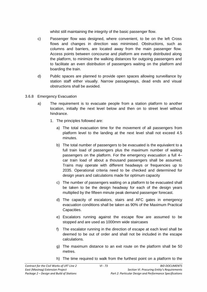
Contract for the Civil Works of LRT Line 2 VI - 73 BID DOCUMENTS East (Masinag) Extension Project Section VI. Procuring Entity’s Requirements Package 2 – Design and Build of Stations Part 2: Particular Design and Performance Specifications
whilst still maintaining the integrity of the basic passenger flow.
c) Passenger flow was designed, where convenient, to be on the left Cross
flows and changes in direction was minimised. Obstructions, such as
columns and barriers, are located away from the main passenger flow.
Access points between concourse and platform are evenly distributed along
the platform, to minimize the walking distances for outgoing passengers and
to facilitate an even distribution of passengers waiting on the platform and
boarding the train.
d) Public spaces are planned to provide open spaces allowing surveillance by
station staff either visually. Narrow passageways, dead ends and visual
obstructions shall be avoided.
3.6.8 Emergency Evacuation
a) The requirement is to evacuate people from a station platform to another
location, initially the next level below and then on to street level without
hindrance.
1. The principles followed are:
a) The total evacuation time for the movement of all passengers from
platform level to the landing at the next level shall not exceed 4.5
minutes.
b) The total number of passengers to be evacuated is the equivalent to a
full train load of passengers plus the maximum number of waiting
passengers on the platform. For the emergency evacuation a full 4–
car train load of about a thousand passengers shall be assumed.
Trains may operate with different headways or frequencies up to
2035. Operational criteria need to be checked and determined for
design years and calculations made for optimum capacity
c) The number of passengers waiting on a platform to be evacuated shall
be taken to be the design headway for each of the design years
multiplied by the fifteen minute peak demand passenger forecast.
d) The capacity of escalators, stairs and AFC gates in emergency
evacuation conditions shall be taken as 90% of the Maximum Practical
Capacities.
e) Escalators running against the escape flow are assumed to be
stopped and are used as 1000mm wide staircases
f) The escalator running in the direction of escape at each level shall be
deemed to be out of order and shall not be included in the escape
calculations.
g) The maximum distance to an exit route on the platform shall be 50
metres.
h) The time required to walk from the furthest point on a platform to the

Contract for the Civil Works of LRT Line 2 VI - 74 BID DOCUMENTS East (Masinag) Extension Project Section VI. Procuring Entity’s Requirements Package 2 – Design and Build of Stations Part 2: Particular Design and Performance Specifications
escalator or stair landing must be considered. Walking speed is 1
meter/second.
i) A check shall be made to ensure that sufficient capacity exists at the
level to which passengers are evacuated as being a place of ultimate
safety so that people can move freely away from stairs and escalators
as they arrive.
j) The escape route capacity including stairs, escalators and
passageways shall not be constricted along the exit route at any point.
k) The emergency occurs in one direction of travel only
l) All levels of the Station Areas and Escape routes out of the station are
considered Places of Safe Passage capable of providing and
maintaining safe conditions for evacuation from a fire at another level.
m) There shall be no escape from a Station Area through any area not
under the direct control of LRTA. Escape via Integrated Entrances
from possible adjacent developments is not an acceptable escape
route.
b) Calculation Method
Maximum Total evacuation time = 4.5 minutes
Total Time (Minutes) = Train Load of Passengers + Waiting Passengers)
Available Capacity
Available Capacity = [(E(move) – 1) x E(ec) ] + [E(stop) x S(ec) ] + [Ws xS(ec) ]
Where:
E(move) = Number of escalators moving in the direction of escape
E(Stop) = Number of escalators moving against the direction of escape
that are stopped and used as 1000mm wide staircases
Ws = Total width of staircases available for escape
E(ec) = One minute Escape capacity of an escalator
S(ec) = One minute Escape capacity per metre width of staircase
3.6.9 Concourse Barrier Gateways
a) Gates shall be provided at the barriers enclosing the Paid area. At least one
gate is installed at the end of each major array of Ticket gates. A minimum
clear opening of 900mm is provided and the gate opens in the outward
direction from the Paid area. These gates are to be opened in the event of an
emergency and be included in the escape capacity calculations.
b) The total number of barrier gates require required in the concourse will depend
on the requirements for Emergency escape.

Contract for the Civil Works of LRT Line 2 VI - 75 BID DOCUMENTS East (Masinag) Extension Project Section VI. Procuring Entity’s Requirements Package 2 – Design and Build of Stations Part 2: Particular Design and Performance Specifications
3.7 Platform Design Standards
3.7.1 General
a) Length
For the purposes of an initial design, the E.E. Platforms shall be 100 meters
long (between the face of Head–wall and Tail–wall units). This allows for the
length of an 4–car train and a stopping tolerance for the E.E. Platforms.
b) Width
The nominal platform width measured from the platform edge to any
continuous (longer than 2000mm) fixed structure shall be a minimum of 4000
mm. The minimum distance from the platform edge to any isolated
obstruction, e.g. columns, shall be 3500mm (an isolated obstruction shall not
be longer than 2000mm). This clearance shall be maintained for safety
reasons, irrespective of passenger loading. No provision for installation of
Screen Doors or barriers along the edge of station platform will be required.
Towards the end of the platform, clear of any main circulation areas,
platforms may taper, but in no case shall they taper to a width of less than
2500mm. Platform widths greater than the minimum may be required at
stations with large passenger flows. The platform edge shall have a safety
margin of 600mm wide with a non–slip surface and a yellow warning strip of
100mm wide of contrasting texture. The platform ends shall be provided with
a 1200mm wide security gate and be installed with a Pressure Mat Alarm
System.
c) Features
A 1600mm wide stair shall be provided at each end of the platform leading to
the track bed. Each Platform shall have a Head–wall Unit and a Tail–wall Unit
located adjacent to the ends of the train. They are for the use of train drivers,
train and station staff, and shall contain designated installations and
equipment. For planning purposes, the size of the recess is 1200mm wide by
850mm deep.
The platform nosing shall be level with the cells of the design train doors of
the rolling stock under normal conditions and for design purposes this shall be
taken as 1080mm above rail level.
Platforms shall be laid to a fall of 1:100 from the platform edge for a distance
of 4000mm towards the back of the platform.
A 2000mm wide continuous membrane shall be installed under the floor
finishes as a platform edge electric insulation.
Markings on the platform to assist and control the flow of passengers
boarding and alighting the trains shall be provided.
A tactile floor strip shall be incorporated within the platform area for the blind
and partially sighted.

Contract for the Civil Works of LRT Line 2 VI - 76 BID DOCUMENTS East (Masinag) Extension Project Section VI. Procuring Entity’s Requirements Package 2 – Design and Build of Stations Part 2: Particular Design and Performance Specifications
3.7.2 Basis of Calculations: Station Capacity Assessment Guide
A platform functioning as a waiting area for trains is divided into functional zones, and
each zone has width requirements:
Waiting Zone–should be sufficiently sized to accommodate all waiting
passengers at a maximum average peak minute density of 0.65m2 per person per
carriage block of the platform
Waiting Zone Block Width = Block Loading x 0.65m2/pax (m)
Block Length
Circulation Zone–provides the space behind or in front of the waiting zone for
passengers to move to and from the platform without being encumbered by
waiting passengers or those boarding or alighting train services
Circulation Zone Width = Peak Minute Flow (m)
40
Minimum width of circulation zone is 1.0m, allowing space for two flows to pass,
single line.
Typically, passengers/pedestrians will keep about 150mm distance from walls and
columns indoor environment.
Activity Zone–includes variety of space including but not limited to: seats for
waiting passengers, retail units, ticket machines, timetables, and advertising
space. A minimum of 0.30m should be incorporated for this zone to reflect the
fact that some customers choose to wait leaning against the wall at the back of
the platform.
Terminal Station Center Island Platform: some may not have the requirement for a
waiting zone as passengers wait at the concourse before being directed to board.
The platform width is driven by the maximum volumes of flow along them.
Platform Width = Peak Minute Flow + Friction Effect (m)
40
Peak Minute Flow: maximum two way flow passing along the busiest section
of the platform, which includes the people passing along it but not using it to
board or alight train services.
In the absence of any data, it should be estimated as 50% of the maximum load
of the arriving train plus, plus 20% of the maximum load of departing train. A
friction effect of 0.50m should be added to each platform edge to reflect the door
opening may represent obstacle to flow and passengers tend to avoid walking too
close to the platform edge.
3.7.3 Platforms General Principles
Element General Principle
Platform Length 4 car train length plus allowance for inaccurate

Contract for the Civil Works of LRT Line 2 VI - 77 BID DOCUMENTS East (Masinag) Extension Project Section VI. Procuring Entity’s Requirements Package 2 – Design and Build of Stations Part 2: Particular Design and Performance Specifications
stopping of 5m
Single Side (speed less
than 165 km/h) Not less than 2.50m wide
Center Island (speed less
Than 165km/h) Not less than 4.00m wide
Columns/Obstructions Should be at least 2.0m clear of platform edge
Headroom
At least 2.5m to structures and platform signs for
width of at least
2.0m from the platform edge over the entire length. At
least 2.3m
for distances greater than 2.0m from the platform
edge
1. Factors to Consider When Establishing the Length of Platforms
The platform length is 93.2m plus 3.4m x 2 (margins at both ends) = 100m. This
length is based on 4 car trains operating on the system. For access/egress on the
platform, the length could be increased to 125m
2. Factors to Consider When Establishing the Width of Center and Side
Loading Platforms:
A tactile warning zone 600mm–915mm wide is to be provided at the platform
edge.
A desirable minimum 2500mm of clear space should be provided between the
edge of the platform and obstructions such as equipment, stairs, escalators,
railings, and structural columns. The absolute minimum clearance is 1700
mm.
For center loading configuration shelters, equipment and amenities are to be
placed in the center portion of the platform.
For side loading configurations shelters, equipment and amenities are to be
placed adjacent to the back wall.
3. Abnormal Conditions
Element Perturbation Evacuation Construction Special
Events
Passageway (1way) 65 pax/m/min 80 pax/m/min 65 pax/m/min 65 pax/m/min
Passageway (2way) 50 pax/m/min N.A. 50 pax/m/min 50 pax/m/min
Stairway (1way) 43 pax/m/min 56 pax/m/min 43 pax/m/min 43 pax/m/min
Stairway ( 2way) 35 pax/m/min N.A. 35 pax/m/min 35 pax/m/min
Escalator 110 people 120 people 110 people 110 people

Contract for the Civil Works of LRT Line 2 VI - 78 BID DOCUMENTS East (Masinag) Extension Project Section VI. Procuring Entity’s Requirements Package 2 – Design and Build of Stations Part 2: Particular Design and Performance Specifications
Element Perturbation Evacuation Construction Special
Events
Concourse
Accumulation Area 0.45m2/pax N.A. 0.80m2/pax 0.80m2/pax
Platform Waiting
Area 0.28m2/pax N.A. 0.45m2/pax 0.45m2/pax
Platform
Circulation Route 65 pax/m/min 80 pax/m/min 50 pax/m/min 50 pax/m/min
Ticket Gates 25 pax/gate 50 pax/gate 25 pax/gate 25 pax/gate
Service Perturbation: a significant delay to the service leading to increased
waiting in the station environment (platform or concourse).
Where train service is 7 to 11 trains per hour, the busiest 15 minute period should
be used.
In case of 15–30 minute delay with probable recovery, physical control measures
are:
No obvious movement of people other than in area 3 meters from building
walls
Potential opening of gates due to barrier line congestion (with loss of
revenue)
Removal of retain seating area
Stop/reverse escalators to slow number of passengers coming into concourse
level
3.7.4 Other Information
Platform widths shall be determined to cater for the greater of the following
scenarios:
a) Normal Service
The Platform width shall be determined by multiplying the peak minute flow by
0.65 sq. m/person and 5 minute head–way, then dividing by the platform length.
b) Delayed Service
The Platform width shall be determined by the peak minute flow, allowing for
two missed head ways or passengers accumulated during 3 train Intervals, at
0.2 sq. m/per person, including alighting passengers from a crush loaded train.
For an island platform, the area between the boundaries of the two platform
faces can be included in the calculation.
Space occupied by stairs, escalators, structure, seating, platform supervisor’s
accommodation etc., is not to be included as part of the platform area.
Normal operating conditions require a reservoir of space for passengers waiting

Contract for the Civil Works of LRT Line 2 VI - 79 BID DOCUMENTS East (Masinag) Extension Project Section VI. Procuring Entity’s Requirements Package 2 – Design and Build of Stations Part 2: Particular Design and Performance Specifications
for a train. An average area of 0.5 square meter per passenger is considered
desirable under these circumstances. The required platform width for the
design peak condition is calculated as follows:
c) For platforms without Platform Screen Doors
Required platform width = 0.6 + (F x SI x0.65)
PL
where: F = the peak one minute flow of boarding
passengers entering onto a single
platform (i.e. wishing to travel in a
given direction)
SI = service interval (minutes)
PL = Platform Length
This formula is based upon the assumption that a 600mm wide zone adjacent
to the platform edge will remain unoccupied when there is no train at the
platform.
3.7.5 Minimum Widths
The minimum acceptable platform width shall also be checked for emergency
conditions against the following design criteria:
a) A delay in service of 2 missed headways amounting to minutes is assumed in
one direction in the peak hour. Therefore 3 headways of accumulated
passengers are gathered on the platform.
b) A full train load of passengers is required to disembark onto the same platform
as the accumulated boarding passengers
c) An average of 0.2 square meter per passenger is acceptable under such
emergency conditions
d) The train will not move from the platform until passengers have begun clearing
the platform and hence the 600mm unoccupied zone adjacent to the platform
edge for platforms without Platform Screen Doors need not be allowed for.
Thus the Required Platform Width = [(3SIxF) + TL] 0.2
PL
Where: SI = Service Interval (minutes)
F = the peak one minute flow of boarding passengers
entering onto a single platform (i.e. wishing to
travel in a given direction)
PL = Platform Length
TL = Train Load of Passengers
3.7.5 Other Features
a) The track alignment through a station shall preferably be straight and level.

Contract for the Civil Works of LRT Line 2 VI - 80 BID DOCUMENTS East (Masinag) Extension Project Section VI. Procuring Entity’s Requirements Package 2 – Design and Build of Stations Part 2: Particular Design and Performance Specifications
However, consideration may be given to using horizontal curvature where
required. Each location shall be judged individually.
b) An under–platform refuge shall be provided below the cantilevered portion of
the platform for the full length of the platform. The minimum horizontal width
from the side of a train to any obstruction shall be 600mm and the full height
from the track slab to the underside of the platform shall be available.
c) Manhole access shall be provided into any under-platform cable or duct
compartment
d) Drains shall be provided in all voids under platforms, where applicable.
e) A Platform Supervisor’s Booth shall be provided on each platform. The box
shall have glazed windows all around and the two boxes on an island platform
may be combined where appropriate. The size shall be 10 sq. m for side
platforms and 15 sq. m for island platforms.
f) A Train Operator’s toilet shall be provided at terminal station platforms and at
others as may be designated by the Engineer. The toilet shall include WC,
basin, mirror, soap dispenser, paper towel dispenser and waste paper bin
unit.
g) Space for fire hydrants, fire hose reels, communications equipment, paging
equipment, lineside advertising panels, and commercial communications
facilities, shall be provided as required for
h) Fire Services, operational and commercial requirements.
I. Passenger access points shall be arranged to encourage the distribution and
collection of passengers evenly along the whole of the platform length. If
required, access points may be offset from station to station to provide an
even loading of passengers in the trains.
3.7.6 Clearances
a) 100mm minimum depth shall be allowed for the provision of any screed and
finishes on the platform. The structural clearances above the platform
finished floor level shall generally be determined by clearances above the
running rail for kinematic envelope. The minimum ceiling height above
finished floor level shall be 3000mm and a 2500mm clearance shall be
maintained to any obstruction (signs, etc.). For design purposes the platform
edge shall be taken as being 1080mm above the rail level (assuming no cant
over the length of the platform) and 1700 mm from the centre line of the track
for straight track stations. Adjustments for horizontal clearance will be
required for curved track. The final dimensions should be checked against
the existing rolling stock and its kinematic envelope.
b) Adequate weather protection shall be provided for all elevated structures, and
electrical facilities, in particular.
3.7.7 Seating
a) A minimum of four banks of three seats shall be provided along the length of

Contract for the Civil Works of LRT Line 2 VI - 81 BID DOCUMENTS East (Masinag) Extension Project Section VI. Procuring Entity’s Requirements Package 2 – Design and Build of Stations Part 2: Particular Design and Performance Specifications
each platform away from the main passenger circulation areas. In the case of
an island platform, consideration shall be given to locate some of the seats in
the central area.
b) The length of each bank of seats shall not exceed 2000mm and the top shall
be fixed at a height of 400mm from the finished floor.
c) Where possible, the seats shall be cantilevered from a back wall to facilitate
floor cleaning. The projection from the wall shall not exceed 500mm.
3.8 Concourse Design Standards
3.8.1 General
The concourse shall be split into two distinct areas; the ticket hall or unpaid area
where passengers digest travel information, and purchase tickets before proceeding
into a paid area from which access is made to the platform level.
3.8.2 Concourse Size
a. The size of the concourse is dependent on the passenger handling
arrangement, the entrance locations and the space requirements for offices and
electrical and mechanical plant at individual stations. The layout of the
concourse is mainly determined by the location of station entrances and the
siting of the access points to the platform. General standards are:
i. Where more than one concourse area is planned then the paid areas are
connected to allow both station staff access to both areas and the
passenger an alternative means of exit.
ii. Public facilities in the concourse shall be located clear of the main
passenger flow routes.
b. The size of the concourse which shall be needed to accommodate the design
passenger flows shall vary with the number of ticket halls, paid areas, and the
way in which the primary concourse elements are arranged. This depends in
turn on escalator and staircase requirements and the location of the entrances.
3.8.3 Access and Space
a) Within the concourse area the station ticket hall shall provide adequate space
for passenger circulation and direct flow lines between ticket counters and
AFC gates. Space shall be allowed for passengers’ decision making and the
provision of public facilities and ticket counters.
b) The paid area shall give direct and clearly defined access to the platforms via
escalators, lifts and stairs. Any public facilities in the paid area shall be
located away from the direct route to the escalators and stairs.
c) A lift for passenger use, particularly the disabled and for first aid and minor
casualties shall be provided between platform and concourse. A similar
facility shall be provided between concourse and street level in association
with at least one principal entrance.

Contract for the Civil Works of LRT Line 2 VI - 82 BID DOCUMENTS East (Masinag) Extension Project Section VI. Procuring Entity’s Requirements Package 2 – Design and Build of Stations Part 2: Particular Design and Performance Specifications
d) All stations must have at least one staircase extending from the concourse to
the platform level. This staircase must be located within the paid area in order
that it may be used when an escalator is out of service and during
emergencies.
3.8.4 Vending and Telephones
a) Space within the concourse area shall be made for free standing Automatic
Teller Machines (ATMs ), vending machines, payment express terminals,
photo booths, TV booths, free standing and/or wall mounted advertising
panels.
b) Space shall be provided for commercial kiosk facilities within the unpaid area
which, during a period at the opening of the system, can be utilized as
temporary ticket offices until such time as stored value tickets have become
an accepted concept and the number of ticketing counters provided can cope
with the predicted demand. The location of the kiosks/temporary ticket
offices shall therefore take into account their initial and intended future use.
3.8.5 Clearances
In all areas a minimum ceiling height of 3000mm shall be adopted with a minimum
height of 2500mm to the underside of local obstructions such as signage. Electrical
and Mechanical installations and service routes shall be contained above the
minimum 3000mm ceiling height, and allowances for these services shall be taken
into account.
Minimum finished floor level to Structural Ceiling 4500mm
This is made up of:
Allowance for cables, ducts etc. 1000mm
Allowance for suspended ceiling, fans and light fittings 200mm
Finished Floor to underside of suspended ceiling 3000mm
A floor finishes zone of 200mm shall be provided. The floor finish shall contain all
necessary floor cable trunking for the provision of Ticket machines and ticket gates
associated with the Automatic Fare Collection system.
3.8.6 Security
Means of securing and closing the station at concourse level needs to be provided
either at the station entrances themselves or at the concourse in the area of the
ticket gates. Crowd control means will be provided at entrances but provision may
need to be made to allow entrances and concourse unpaid areas to be used for
public access outside normal railway operational hours.
3.8.7 Acoustics
Due consideration shall be given to the acoustic environment of both the platform and
concourse public areas with particular reference to the design and performance of
the public address system.

Contract for the Civil Works of LRT Line 2 VI - 83 BID DOCUMENTS East (Masinag) Extension Project Section VI. Procuring Entity’s Requirements Package 2 – Design and Build of Stations Part 2: Particular Design and Performance Specifications
3.9 Entrances
3.9.1 General
Station entrances provide the link between the station concourse and the
surrounding streets, and their locations must reflect the separate constraints of both.
They may also cater for inter modal interchange which may include bus transfer, taxi,
motorised rickshaws, motorcycle and bicycle transfer, kiss and ride and park and ride
facilities. Covered integrated links with such facilities may be considered if the
predicted passengers warrant.
3.9.2 Access Requirements
a) The position of entrances shall be determined by the juxtaposition of
buildings, location of roadways, footpath width, space availability and flow
directions of passenger traffic.
b) Required entrances are to be within the right of way under the control of the
LRT Line 2.
c) Entrances at Street Level shall be easily identifiable.
d) The widths of entrances shall take into account predicted passenger flows
and available space. Entrances to stations shall have adequate capacity to
satisfy predicted passenger flows and emergency evacuation requirements.
e) Entrances to stations via developments (Integrated Entrances) are
considered additional facilities and are not to be included in the assessment
of minimum passenger handling or Emergency Escape facilities
f) Each entrance shall contain a closure device for closure of the station during
non-operational hours and be used as a means of crowd control.
3.9.3 Flood Control
a) All entrances extending to street level must be protected against flooding.
This protection shall be by the provision of a minimum of 3 steps up to a
landing (+450mm minimum).
b) The stairwell on all pavement entrances shall be surrounded by a solid
concrete balustrade 1200mm high. The height of the balustrade must be
checked against maximum flood conditions that could arise.
3.9.4 Materials Considerations
a) The selection of materials shall not radically depart from those used within
stations and shall be robust, hard wearing and maintenance free.
b) Floor finishes are to be laid to adequate falls in order to allow for the
occurrence of any seepage, rainwater (from foot traffic), washing water, etc.
Drainage provisions, including sumps and pumping facilities shall be included.
3.9.5 Integrated Entrances
a) An integrated entrance is an entrance incorporated within a development and
may not be under the direct control of the LRTA. It shall not form part of the

Contract for the Civil Works of LRT Line 2 VI - 84 BID DOCUMENTS East (Masinag) Extension Project Section VI. Procuring Entity’s Requirements Package 2 – Design and Build of Stations Part 2: Particular Design and Performance Specifications
required exit route for station, concourse or the development, and shall not be
included in capacity calculations.
i. Fire Precautions
All provisions with respect to the fire safety of the station and the
development shall be agreed with the Fire Services who may require
specific safety requirements at particular locations. However, as a
minimum the following provisions shall be incorporated into the design.
b) A positive break in the form of a fully ventilated open well shall be provided
between station exit routes and integrated entrances. The open well shall give
access directly to open air and be enclosed by imperforate four–hour FRP
walls during its passage though the development. It shall be ventilated by
natural means and with exhaust fans, if natural ventilation means are not
available. The cross sectional area of the well shall not be less than half that
of the station entrance passageway. The effective cross–sectional area of
the discharge point of the well shall not be less than that of the well.
c) The four–hour fire separation lobby shall not be used for any other purpose.
Four hours separation by means of walls, floors and smoke/heat operated
shutters shall be maintained between the railway and the development. The
fire shutters shall have audible and visual alarms and the signals shall be
relayed back to the Station Control Room.
3.9.6 Entrances in Developments
a. Entrance structures within a development must be designed in such a way that the use of the entrances is not adversely affected by any future redevelopment of the building structure.
b. Entrances must be separated from the development by four–hour FRP structure up to the discharge point of the entrance onto the footpath.
c. Flood protection, as required for all standard station entrances is to be provided.
d. Any incidental water, as itemized in Clause 6.3, shall be similarly catered for.
3.9.7 Development Entrances under the control of LRTA
a) Where a horizontal or vertical entrance to an Integrated Commercial Area is
provided and this is under the direct control of the LRT Station Management,
it may be used as part of an escape route in the event of a fire. The
Integrated Commercial Area will need to be designated as a Place of Safe
Passage and will therefore come under stringent Fire Precautions and the
design will be agreed on an individual basis.
3.10 Escalator, Stair and Lift Design Standards
3.10.1 Street and Concourse Requirements
a) Stairs shall be provided for both upward and downwards movement. The rise of the stairs shall preferably be limited to 3500mm. Site conditions may cause an increase in this dimension.

Contract for the Civil Works of LRT Line 2 VI - 85 BID DOCUMENTS East (Masinag) Extension Project Section VI. Procuring Entity’s Requirements Package 2 – Design and Build of Stations Part 2: Particular Design and Performance Specifications
b) For the benefit of the disabled, all stations must contain at least one entrance where access can be obtained without the use of an escalator. If possible two entrances (one at each end of the station) shall contain stairs. Additional consideration to ensure unaided accessibility by the disabled is defined in the section relating to the Design for the Handicapped.
i. Use of Escalators
Where there is a rise in the lower portion of less than 3200mm, an
escalator shall not normally be provided. Thus, where the total rise from
street level to concourse is less than 6700mm, escalators shall normally
only be provided where they can be arranged to ascend directly from
street level. If the total height difference from street level to concourse is
greater than 10000 mm a down escalator shall also be provided in the
lower portion.
For greater rise heights, the entrances shall be divided into two portions.
The upper portion shall consist of stairs for both up and down movement,
the lower portion shall consist of an escalator for upward movement and a
staircase for downward movement.
Where entrances contain down escalators, in addition to up escalators, an
auxiliary stair shall be provided if possible.
When down stairs parallel up escalators, their width shall not be less than
2000mm except that the width of an auxiliary stair may be reduced to
1800mm.
A staircase taking traffic from an escalator must be of sufficient width to
provide capacity at least equal to the escalator, e.g. the incoming stair in
the upper portion of an entrance taking traffic from an up escalator shall
be not less than 2400mm wide.
Where escalator(s) are provided in the lower portion, the landing between
the upper and lower portions shall not be less than 8500mm free length
from the escalator working points. If the entrance is angled there shall be
not less than 5000mm straight from the working point, but if there is a
choice of direction not less than 8500 mm.
ii. Other Requirements
Where the width of the staircase is 4500mm or more a center handrail
shall be provided on the stairs (but not the landings)
Where down staircases are parallel to escalators, the first riser shall
preferably be positioned one tread width from the lower EWP towards the
upper EWP, but the total rise may dictate otherwise.
Entrance/ exit stair or escalator shall have enlarged roof or rain canopy at
street level (or open air) to give a greater passenger waiting area.
3.10.2 Concourse/Platform Requirements
a) Where possible, the escalators shall be evenly distributed along the whole

Contract for the Civil Works of LRT Line 2 VI - 86 BID DOCUMENTS East (Masinag) Extension Project Section VI. Procuring Entity’s Requirements Package 2 – Design and Build of Stations Part 2: Particular Design and Performance Specifications
length of the station so as to avoid a concentration of passengers at a
particular area. An escalator working point shall preferably be not less than
12000mm from any obstruction across the direct path of passengers, and in
no circumstances less than 11000mm. Where escalators are arranged in
banks, the clear distance from the escalator working point shall be increased
by at least 1000mm for each additional escalator. Traffic flow across the path
of passengers is deemed as an obstruction.
i. Safety
The combined capacity of stairs and escalators must be capable of
satisfying the emergency evacuation requirements or normal passenger
handling requirements, whichever are the greater.
The distance from escalator working points to ticket gates shall be not
less than 12000mm.
A smoke containment bulkhead, extending 3000mm from the finished
floor level to the structural soffit, must be provided at the foot of all stairs
and escalators serving the platform level.
ii. Dimensions
In paid areas escalators shall be used where the height difference is
greater than 2500mm.
All stations must have at least one designated staircase, minimum
1800mm wide, from the lowest to the highest levels.
The minimum distance between working points of escalators working in
opposing directions is 25000mm.
iii. Other Requirements
Where a staircase is parallel to an escalator the first riser shall preferably
be positioned one tread width from the lower EWP towards the upper
EWP, but the total rise may dictate otherwise.
Where possible, passengers shall not have to travel from one passenger
level to the next by more than one escalator.
No access shall be allowed from public stairways to plant–room areas.
3.10.3 Lifts for the Disabled
a) Lifts shall be provided for the ambulant disabled to gain access from the
street level to the concourse and then to the platform levels. The lift shall not
by-pass the paid area gate–line, therefore, it will be necessary to have more
than one lift. Ramps shall be provided where a change in level is not
negotiable by lift.
i. The lifts serving the street level shall be weatherproof and flood protected
with fire rated separation from any adjacent development areas.
ii. These lifts shall be available for use by the Disabled and by any other

Contract for the Civil Works of LRT Line 2 VI - 87 BID DOCUMENTS East (Masinag) Extension Project Section VI. Procuring Entity’s Requirements Package 2 – Design and Build of Stations Part 2: Particular Design and Performance Specifications
passenger.
3.10.4 Escalators
a) All escalators shall be of the heavy–duty reversible type with a design
maximum practical capacity of 150 persons per minute based on a service
speed of 0.75 m/sec.
i. Criteria
The following requirements are given for planning purposes:
Inclination 30 degrees
Step speed 0.75 m/s
Step width (min) 1000 mm
Number of flat steps at upper landing 5 (min)
Number of flat steps at lower landing 4 (min)
ii. Headroom above escalator step
The following minimum dimensions shall be provided:
Minimum vertical clearance from
step nosing line to soffit of structure 2750mm
Clear headroom from step nosing
line to finished ceiling 2500mm
(2300mm min)
iii. Side Clearances of the well–way structure
Single and parallel escalators
Vertical Rise
Distance from escalator center line to:
Center Line of Adjacent Escalator (mm)
Face of Wall (mm)
Below 10000 mm 2200 1350
From 10000 mm to 15000 mm
24003 1650
From 15000 mm to 20000 mm
2600 1650
Above 20000 mm 2700 1850

Contract for the Civil Works of LRT Line 2 VI - 88 BID DOCUMENTS East (Masinag) Extension Project Section VI. Procuring Entity’s Requirements Package 2 – Design and Build of Stations Part 2: Particular Design and Performance Specifications
Crisscrossed Escalators
Vertical Rise
Distance from escalator center line to
Center Line of Adjacent
Escalator (mm)
Face of Wall (mm)
Both Escalators with rise
below 10000 mm 2900 1350
One Escalator with rise
below 10000 mm and
the other with rise above
10000 mm
3200
Rise>10000 mm:
1650
Rise<10000 mm:
1350
Both Escalators with
rise above 10000 mm 3500 1650
Both Escalators
with rise above
20000 mm
3900 1850
The Side Clearance Standards shall be used for design purposes. In
circumstances where it is not possible to achieve this standard and/or
where some variation to the above standards in specific local areas would
facilitate the design, reduced clearances may be accepted by agreement.
The Side Clearances Standards apply for the entire length of the well–way.
For any other special arrangements not covered in the above tables, the
well–way design shall be referred to the LRT for further details.
iv. Side Clearance on Passenger Side
Minimum distance from the escalator center
line to the inner surface (finished dimension)
of the surrounding parapet wall or any fixed obstacles 1000mm
Clear height over the above distance 2300mm(min)
Parapet wall height surrounding concourse/
platform escalators at upper landing 1165mm (min)
Where the escalator passes through a floor and the horizontal distance
from the centre line of the nearer handrail to the ceiling or slab soffit is less
than 550mm the intersection must form a straight vertical surface of not
less than 450mm in height to avoid any wedging hazards.
v. Headroom in Machinery Spaces
Installation with Drive Motor below Escalator truss: Headroom at the upper
machinery space, defined as the vertical distance from finished floor level at
the escalator landing to the upper surface of the machine room floor slab,

Contract for the Civil Works of LRT Line 2 VI - 89 BID DOCUMENTS East (Masinag) Extension Project Section VI. Procuring Entity’s Requirements Package 2 – Design and Build of Stations Part 2: Particular Design and Performance Specifications
shall be a minimum of 3500mm
Installations with Drive Motor behind Escalator Truss: Headroom at the
upper machinery space, defined as the vertical distance from the soffit of
the slab incorporating the escalator landing to the upper surface of the
machine room floor slab, shall be a minimum of 2300 mm
Headroom in the Lower Machinery Room Spaces: The clear height from the
upper surface of the base slab of the lower machinery space to the soffit of
the structure slab incorporating the lower escalator landing shall be a
minimum of 2100mm. Minimum clearance under down stand beams to be
1800mm
vi. Size of Machinery Spaces
Upper Machinery Space:
For installations with drive motor below escalator truss: The distance
from the Escalator Working Point (EWP) to the inner surface of the
end wall shall be a minimum of 6000mm.
For installations with drive motor behind escalator truss: The
distance from the EWP to the inner surface of the end wall shall be a
minimum of 8500mm.
Lower Machinery Space:
The distance from the EWP to the inner surface of the end wall shall be
a minimum of 6000mm. If possible it is desirable to increase this
dimension to 6500mm.
vii. Slab Below Escalator Truss
An inclined slab shall be constructed below the escalator truss to
provide necessary fire separation. Steps shall be formed on the upper
surface of this slab along the sides of the truss. The perpendicular
clearance between the underside of the truss and the nose line of the
steps shall be 850mm minimum. However, in restricted circumstances
a minimum of 500mm shall be permissible.
viii. Lifting Facilities over the Escalator Well–way for Installation
Cast–in sockets shall be provided at suitable locations for the
installation of escalators. This will be required for the initial installation of
the escalators during the construction of the station and for the future
installation of escalators at previously determined locations.
ix. Escalator End and Intermediate Supports
The end supports shall be designed to the information given by the
escalator manufacturer. Escalator truss trimming angles and bearing
plates will be supplied by the escalator manufacturer.
Intermediate supports shall be provided where the vertical rise exceeds
5000mm.
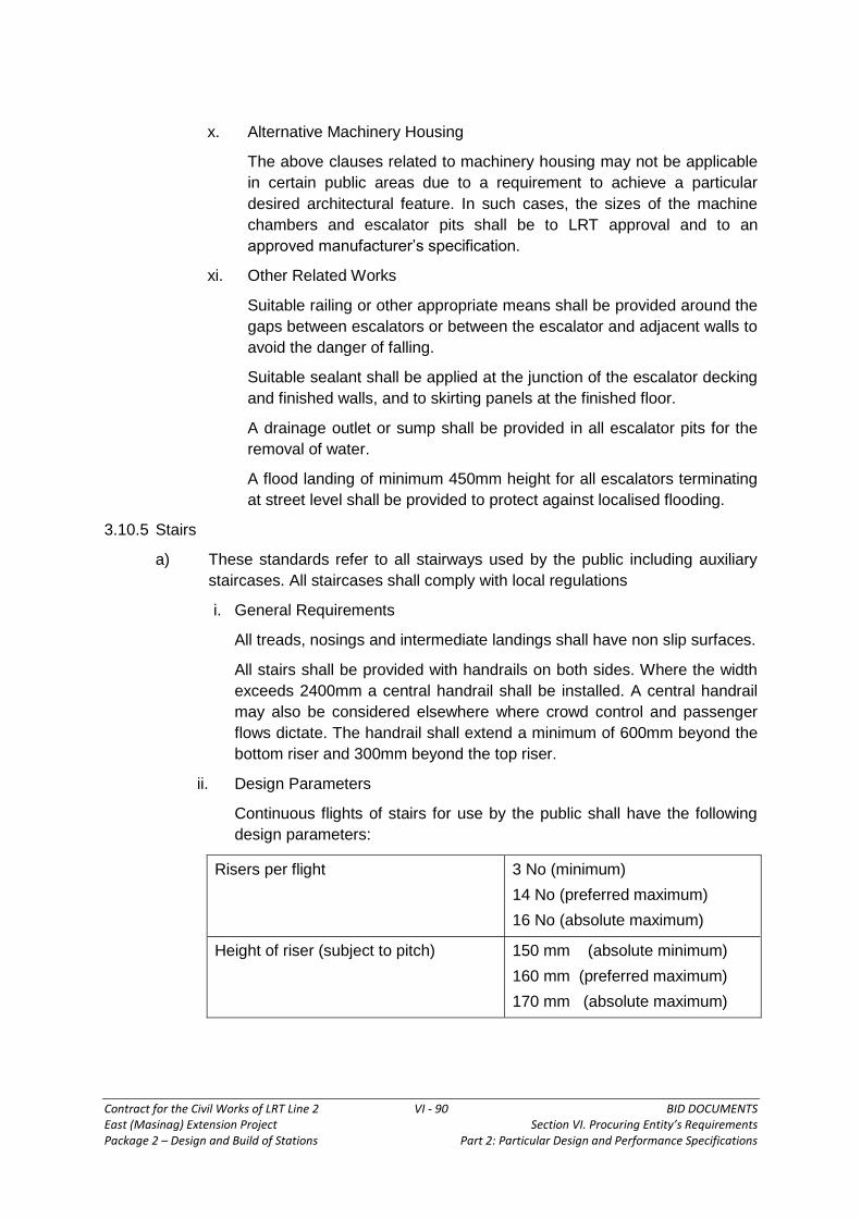
Contract for the Civil Works of LRT Line 2 VI - 90 BID DOCUMENTS East (Masinag) Extension Project Section VI. Procuring Entity’s Requirements Package 2 – Design and Build of Stations Part 2: Particular Design and Performance Specifications
x. Alternative Machinery Housing
The above clauses related to machinery housing may not be applicable
in certain public areas due to a requirement to achieve a particular
desired architectural feature. In such cases, the sizes of the machine
chambers and escalator pits shall be to LRT approval and to an
approved manufacturer’s specification.
xi. Other Related Works
Suitable railing or other appropriate means shall be provided around the
gaps between escalators or between the escalator and adjacent walls to
avoid the danger of falling.
Suitable sealant shall be applied at the junction of the escalator decking
and finished walls, and to skirting panels at the finished floor.
A drainage outlet or sump shall be provided in all escalator pits for the
removal of water.
A flood landing of minimum 450mm height for all escalators terminating
at street level shall be provided to protect against localised flooding.
3.10.5 Stairs
a) These standards refer to all stairways used by the public including auxiliary
staircases. All staircases shall comply with local regulations
i. General Requirements
All treads, nosings and intermediate landings shall have non slip surfaces.
All stairs shall be provided with handrails on both sides. Where the width
exceeds 2400mm a central handrail shall be installed. A central handrail
may also be considered elsewhere where crowd control and passenger
flows dictate. The handrail shall extend a minimum of 600mm beyond the
bottom riser and 300mm beyond the top riser.
ii. Design Parameters
Continuous flights of stairs for use by the public shall have the following
design parameters:
Risers per flight 3 No (minimum)
14 No (preferred maximum)
16 No (absolute maximum)
Height of riser (subject to pitch) 150 mm (absolute minimum)
160 mm (preferred maximum)
170 mm (absolute maximum)

Contract for the Civil Works of LRT Line 2 VI - 91 BID DOCUMENTS East (Masinag) Extension Project Section VI. Procuring Entity’s Requirements Package 2 – Design and Build of Stations Part 2: Particular Design and Performance Specifications
length of tread (subject to pitch) 280 mm (absolute minimum)
300 mm (preferred)
340 mm (absolute maximum)
Intermediate landing width 1500 mm (absolute minimum)
2000 mm (preferred)
Stair width
Unidirectional
Bi-directional
2000 mm (desirable)
1800 mm (absolute minimum)
2400 mm (absolute minimum)
Length of intermediate Landings Lesser of 2000 mm or width of
stairs with absolute minimum of
1800 mm.
Length of Flood Landing 2500 mm
Vertical Clearance 2700 mm (min.) measured from
the finished step level (on line of
nosings) to underside of
suspended ceiling
2350 mm (min.) measured from
finished step level to underside of
signs.
Height of Balustrade 1165 mm
Handrail 850 mm high, 50 mm diameter
45 mm clearance between
handrail and inside balustrade or
wall finish.
Falls at entrance stairs Flood landings are to fall 1:100
towards the street with side
channels. Intermediate landings
are to fall towards the concourse.
Staircases fed by an escalator shall be made sufficiently wide to provide
capacity at least equal to that of the escalator.
The width of a staircase shall be measured from the finished surfaces of the
inside faces of the balustrades or staircase walls. The only projection
permissible will be the handrail.
No open risers shall be allowed.
3.10.6 Lifts
The following design parameters are listed to facilitate initial station planning
only. All dimensions must be adjusted to suit the sizes of equipment and

Contract for the Civil Works of LRT Line 2 VI - 92 BID DOCUMENTS East (Masinag) Extension Project Section VI. Procuring Entity’s Requirements Package 2 – Design and Build of Stations Part 2: Particular Design and Performance Specifications
maintenance requirements
a) Lift for the Disabled / Casualty
Width
Depth
Height
Internal car dimensions 1500mm
2500mm
2300mm
Width
Height
Minimum car and landing
opening
1300mm clear (2 panels
opening)
2100mm clear
Width
Depth
Lift well approx. size 2450mm or 2100mm
3200mm or 2450mm
Hydraulic &
Traction Lift
Headroom in lift well
from top landing
4400mm minimum
Up or down Speed (fully loaded) From 0.6 to 1.0 m/s
depending on the depth of the
station box.
Lift Speed
0.6 m/sec
1.0 m/sec
Pit Depth
1500mm
1900mm
Dimensional requirements for a glazed lift may differ from the above. The Lift
designer/manufacturer shall be consulted for requirements related to a glazed
lift shaft and lift car.
Handrails of 45mm to 50mm outside diameter suitable for use by the disabled
shall be provided at the rear and sides of the car. They shall be mounted 850
mm above the car floor and extend to within 150mm of the corners
Landing and car control buttons shall be fixed within 900mm to 1200mm
above the landing or car floor. The distance from the front wall shall be at least
400 mm. Suitable tactile indications, identifying the level shall be placed
adjacent to the control buttons.
A 2–way communication panel shall be installed adjacent to the lift landings as
call points to enable the rapid and unambiguous identification of those levels
with disabled persons requiring evacuation.
b) Lift Type
All lifts shall preferably be of the traction type, hydraulic lifts shall be used
where the machine room cannot be located directly above the lift shaft.
The disabled lifts shall also comply with relevant statutory design
requirements on access for the disabled.

Contract for the Civil Works of LRT Line 2 VI - 93 BID DOCUMENTS East (Masinag) Extension Project Section VI. Procuring Entity’s Requirements Package 2 – Design and Build of Stations Part 2: Particular Design and Performance Specifications
c) Emergency Doors
When the distance between consecutive landing doorsills exceeds 11000mm,
intermediate lift shaft emergency doors shall be provided, so that the distance
between sills is not more than 11000mm. The emergency doors shall
preferably be identical to normal lift landing doors with the same clear height
and width. Otherwise, it shall have a minimum clear height of 1800 mm and a
minimum clear width of 500mm.
d) Ventilation of Shaft
A ventilation opening shall be provided at the top of the lift shaft. This
opening shall have a minimum net free area of 0.15 sq. m or 1% of the
horizontal cross sectional area of the lift shaft, whichever is the larger. The
opening shall vent to the open air directly or via ducting or the lift machine /
pulley room.
e) Inspection Trap
For hydraulic lifts only, an inspection trap shall be provided for maintenance
access to the over–speed governor installed inside the lift shaft. This trap
shall have a clear opening size of 750mm x 750mm and shall be located in
the wall near the top of the lift shaft. Permanent means for access to this trap
from outside the lift shaft shall be provided.
3.11 Design for the Handicapped
3.11.1 General
In 1998, The Central Public Works Department of the Ministry of Urban Affairs and
Employment, India published a document titled “Guidelines and Space Standards for
Barrier Free Built Environment for Disabled and Elderly Persons.” The principles
outlined in this document shall be incorporated into the design of the stations. This
document sets out background information, advisory information and mandatory
standards for the overall guidance of designers relevant to various disciplines.
The whole of the document shall be applied as appropriate to the design of the
stations and associated areas. Of particular interest is Chapter 16 devoted to
Railway Stations which is quoted as follows:
3.11.2 Approach to Station
The approach should not have a difference in level. If a level difference is
unavoidable, install a ramp or a ramp plus staircase.
(The ramp should comply with the guidelines for “Ramps” and the stair should comply
with those for “Steps and Stairs”)
3.11.3 Paved Surfaces
a) Platform Entrances and Exits
The station entrance/exit should not have a difference in level. If a level
difference is unavoidable, install a ramp or a ramp plus staircase.

Contract for the Civil Works of LRT Line 2 VI - 94 BID DOCUMENTS East (Masinag) Extension Project Section VI. Procuring Entity’s Requirements Package 2 – Design and Build of Stations Part 2: Particular Design and Performance Specifications
(the ramp should comply with the guidelines for “Ramps” and the stair
should comply with those for “Steps and Stairs”)
It is desirable that space be marked out near the entrance/exit for vehicles
carrying wheelchair users.
(For other details about parking lots, see “Parking Space”)
b) Reservation or Information Counters Reservation or information counters
should have unobstructed approaches for wheelchair users. Counter heights
should not be in excess of 850mm.
c) Concourse
The width of the concourse should be at least 1800mm
The concourse should not have a difference in level. If a level difference is
unavoidable, install a ramp or a ramp plus staircase.(The ramp should
comply with the guidelines for “Ramps” and the stair should comply with
those for “Steps and Stairs”)
The floor surface of a concourse should be made of non-slip material. At
places, where the difference in level such as stairs, it is desirable that the
appearance of the surface material be changed using colour contrast.
Ensure that columns, signboards, and other fixtures do not protrude from
wall surfaces (See “Protruding Objects” ref. Page No.33)
Install guiding blocks on the concourse for persons with impaired vision
(see “Guiding Blocks” Ref. Page No. 46).
d) Stairs
For details, see the guidelines for “Steps and Stairs”
3.11.4 Lifts (Elevators)
Supply and Install a lift (elevator) as a means to enable passengers with disabilities
to move between floors. For the lift (elevator), install two guiding blocks for persons
with impaired vision 300mm away from the call button. For other details, see “Lifts”
3.11.5 PWD Toilet
Install a toilet and washstand suitable for use by wheelchair users and other
passengers.
3.11.6 Ticket Gates
a) At least one of the ticket gates should be wide enough to allow wheelchair users to pass through easily.
b) One of the ticket gates should have a continuous line of guiding blocks for persons with impaired vision.
c) For other details, see “Guiding Blocks”
3.11.7 Platforms
a. The platform should have one row of dotted guiding blocks for persons with

Contract for the Civil Works of LRT Line 2 VI - 95 BID DOCUMENTS East (Masinag) Extension Project Section VI. Procuring Entity’s Requirements Package 2 – Design and Build of Stations Part 2: Particular Design and Performance Specifications
impaired vision, 800mm or more from the edge.
b. The paved surface of the platform must be made with a non–slip material
c. Stairs, kiosks and dustbins on the platform must not hinder the clear passage of persons with impaired vision and wheelchair users.
d. A bench should be installed on the platform, having guiding block around it.
3.11.8 Railway and Metro Corridor Passenger Vehicles
a) Doors
Car doors should be wide enough for wheelchair users [minimum 900mm]
The gap between car doors and the platform should be reduced to an
absolute minimum.
b) Aisles
Aisles should be wide enough for the passage of wheelchair users.
c) Wheelchair Space
A space for a wheelchair should be made available at the side of the door.
The space should be indicated inside and outside the car by using the
universally recognised symbol for wheelchair accessibility.
Install a ring–strap or other appropriate safety grip for wheelchair users to
hold onto.
3.11.9 Information
a) The information board should be made easily readable by using sufficiently large text size, distinct contrast and illumination.
b) It is desirable that in addition to a printed version of train schedule, table of fares and other travel information also be in Braille.
c) For hearing impaired persons an electronic sign board of appropriate size and height should be displayed on each platform at conspicuous location for all announcements made by the railways.
3.11.10 Information Signs and Announcements
a) Install a map of train routes
b) Announce and provide in each car a visual display of the names of stations
and route.
3.12 Corridor and Ramp Design Standards
3.12.1 Corridors
The width of corridors or passageways in public areas shall be determined by
capacity requirements subject to the minimum dimensions given below:
minimum for unidirectional movement 1800mm
minimum for bi-directional movement 2000mm
minimum for staff only movement 1200mm

Contract for the Civil Works of LRT Line 2 VI - 96 BID DOCUMENTS East (Masinag) Extension Project Section VI. Procuring Entity’s Requirements Package 2 – Design and Build of Stations Part 2: Particular Design and Performance Specifications
3.12.2 Ramps
Ramps shall only be used for small changes in level or for use by wheelchairs and
the following gradients shall apply:
preferred maximum gradient 1:20
absolute maximum gradient 1:12
Ramps shall be a minimum width of 1200mm for uni–directional movement and
1500mm for bi–directional movement. Rest platforms should be considered for long
ramps (exceeding 10m) provided for wheelchair users. Rest platforms should
provide a level area 1800mm long at intervals of approximately 10m.
3.13 Passenger Amenities
3.13.1 General
A number of amenities shall be provided for the use of passengers within the station.
Where these involve stationary passengers then the facilities shall be located clear of
the main passenger flows.
3.13.2 Advertising
a) Advertising will be an important source of revenue for the LRT but the extent
of the demand for advertising will depend on market forces. Potential sites for
advertising within a station shall be located so as not to conflict with the
principal requirement of the provision of signage to direct passengers,
especially in an emergency.
b) There are various advertising media that shall be used both within and
outside the station which include:
i. 3–Dimensional Advertising
3D Media - large models of products or company
logos
Display Cabinets - for company products
ii. 2–Dimensional Electronic Advertising
Light Emitting Diode - Newscaster, information services
Neon sign - Company logo / product information
iii. Audio Advertising
Radio style advertising, pre-recorded and played over station/train intercom.
iv. Mechanical Advertising
Collapsible Billboards
Retractable Screen
Flip-sides - Billboard with 3 times space, rotates
when required to reveal different

Contract for the Civil Works of LRT Line 2 VI - 97 BID DOCUMENTS East (Masinag) Extension Project Section VI. Procuring Entity’s Requirements Package 2 – Design and Build of Stations Part 2: Particular Design and Performance Specifications
adverts
Q – Board - Successor to the flipside giving space
for many more advertisements
v. Moving Image
TV Monitors - used in either single units or in blocks
of screens
Holograms - Lasers
vi. Truemation - 2–Dimensional
vii. Directly applied - advertisements directly painted onto
surfaces
Superlites - back–lit advertisements
Projection - still image directly projected onto
screens or walls
Billboards/Posters - conventional media
3.13.3 Design Criteria
A combination of many of the above means of advertising may be adopted at
stations. Whatever media is used it must be integrated into the station design and
not be treated as an add on element at a later date. All wiring and fixings must be
concealed. Provision shall be made for cast in conduit and fixings for advertising
media at identified sites whether or not the media is installed at the opening of the
railway. Attention shall be paid to ensuring maintenance access to these zones.
3.13.4 Commercial Areas within the Stations
Areas for commercial use shall be located at stations. During period upon the
opening of the railway system some of these areas will need to be used as temporary
ticketing offices for the sale of single and multi–journey tickets.
3.14 Signage and Graphic
3.14.1 General
This particular Design and Performance Specification (PDPS) deals with the
requirements for the provision of a Signage and graphics System and associated
components relating to the “identification signs”, “directional signs”, “information
signs” and “regulatory signs” within the stations and their surrounding environs which
forms part of the scope of works of the Contractor. This Specification also define and
visualize materials and workmanship requirements for bidding and construction
purposes.
a) Passenger information signs located at stations will be many and varied
ranging from station entrance signs to train indicator panels and information
panels.
b) Signs are to be provided in a dual language format

Contract for the Civil Works of LRT Line 2 VI - 98 BID DOCUMENTS East (Masinag) Extension Project Section VI. Procuring Entity’s Requirements Package 2 – Design and Build of Stations Part 2: Particular Design and Performance Specifications
c) All signage hardware shall be of a consistent range of materials and
size/proportions.
d) Location of clock and public information system to be clearly identified
3.14.2 Scope of Work
a) The Scope of Works shall cover the preparation of the design and supply of a
complete Signage and Graphics System for the LRT Line 2 East (Masinag)
Extension Project, if any, and disposing them as directed by the Engineer.
b) The document sets down the criteria and means by which the Bidder shall
fulfil his obligations. Performance criteria, where specified, shall be
considered as minimum requirements for which the Bidder’s proposals shall
be based.
c) The signs shall be installed at conspicuous places at the stations for safety
and directional guidance of the end users (see Signage location on Tender
Drawings). The Bidder shall carefully study and consider all necessary details
for providing a signage system of high standard and uniform quality.
3.14.3 Interface
3.14.3.1 Coordination
The Contractor shall coordinate and interface with Employer and/or Engineer
to obtain information on the Signage and Graphics.
3.14.3.2 Other Trades
The Bidder/Contractor shall:
a. Fully acquaint himself with the Works being carried out by Other
Contractors, if any, before and throughout the design and installation of the
Signage and Graphics and coordinate as necessary with others.
b. Take particular care to comprehensively advise the
Subcontractor/Agency responsible for the provision of electrical equipment,
what equipment will be required to service the Signage. This will include all
necessary incidentals to the switching on and off of different signage or parts
of signage as specified.
3.14.3.3 Supplemental Information
a. The Contractor shall provide the name of the sub–contractor/supplier and
products which he intends to use to carry out this Works.
b. The Contractor shall submit all relevant information and calculations
sufficient to demonstrate compliance to this PDPS and for submission to
the Relevant Authorities.
3.14.3.4 Prototypes
a) The Prototype installations to be provided by the Contractor shall have the minimum features, facilities and capabilities specified in this PDPS.

Contract for the Civil Works of LRT Line 2 VI - 99 BID DOCUMENTS East (Masinag) Extension Project Section VI. Procuring Entity’s Requirements Package 2 – Design and Build of Stations Part 2: Particular Design and Performance Specifications
b) Prototypes shall be constructed to demonstrate the appearance and operation of complete signage installations and in this respect the trial installation is required to reflect, as far as possible, the conditions and support arrangements present in a station. The prototype shall incorporate all fixings, seals, finishes, attachments, details and appurtenances to fully reflect the ‘as-installed’ Site condition.
c) The prototype installations proposed by the Contractor shall demonstrate to the Engineer’s satisfaction, the requirements or the following, which shall be tested.
i. The graphic and architectural appearance,
ii. The fixing principle,
iii. The electrical installation, and
iv. The illumination as specified.
3.14.4 Performance Requirements
3.14.4.1 Life Expectancy and Maintenance
a. The design of the equipment shall be such that replacement of parts (except
lamps) shall not become necessary under normal wear and tear for a period of
five (5) years from the date of completion of the work. The design life of the
Signage and Graphics as a whole shall be for a period of at least 20 years. The
performance criteria shall be satisfied during the full design life.
3.14.4.2 Environmental Criteria
a. The Contractor shall ensure that the Signage and Graphics System shall be fully
capable of resisting the atmospheric conditions likely to occur at the installed
locations.
b. Then Contractor shall ensure that the Signage and Graphics shall withstand,
without, distress or progressive deformation, the following extremes of ambient
air temperatures and humidity. No condensation shall take place either on the
internal surfaces or within the interstitial construction thickness of the Signage
and Graphics under the following temperature and humidity conditions:
Ambient Temperature : Min +15ºC –Max. +40ºC
Relative Humidity : Min 60% -Max. 100%
c. The Contractor shall design the Signage and Graphics System such that no
deleterious effect shall result from direct exposure to sunlight.
3.14.4.3 Features of Signage
a. Illumination requirements:
Performance Description Unit Requirement
Uniformity Ratio of min. to max.
illumination Ratio Max. 1 to 3
Brightness Average brightness of white
foreground Candle/sm. Min. 500

Contract for the Civil Works of LRT Line 2 VI - 100 BID DOCUMENTS East (Masinag) Extension Project Section VI. Procuring Entity’s Requirements Package 2 – Design and Build of Stations Part 2: Particular Design and Performance Specifications
Brightness Average brightness of white
background Candle/sm. Min. 20
Brightness
Average brightness of hidden
message
Candle/sm.
Min. 150 – Not to be
exceeded by another
illuminated color. To
be 0 when ‘hidden’
Brightness
Relative output expressed as
percentage of light emitted
with reference tube and ballast
% Min. 95
Specular
reflectance Reflector output % Min. 23
Reflector Total reflectance % Min. 88
Reflector Diffuse reflectance % Min. 78
b. Signage and Graphics panel
Unless specified or approved otherwise, shall be as indicated in Tender
Drawings.
c. Illumination
Lamps shall be of low energy fluorescent lamps, fitted into the signage to
facilitate access to the lamp chamber for replacing the lamps or maintenance to
the ballast and lamp starters. It shall not be necessary to remove the sign graphic
panel of the Sign to access the lamps. The illumination shall be flicker free.
d. Moveable parts and mechanisms
The Contractor shall;
i. Ensure all mechanisms are failsafe.
ii. Provide safety restraints such that all movable assemblies are built-in to
prevent accidental dislodgement and subsequent collapse during
maintenance.
iii. Design all movable parts and mechanisms to be maintenance-free wherever
possible, or be located at positions where maintenance to these parts can be
reached without dismantling the Signage and Graphics support or structure.
iv. Ensure all Signage and Graphics allow access to internal electrical
components without providing access to the general public.
v. Provide all information/Bulletin panels to incorporate locks to removable
frames and panels to prevent access by unauthorized persons.

Contract for the Civil Works of LRT Line 2 VI - 101 BID DOCUMENTS East (Masinag) Extension Project Section VI. Procuring Entity’s Requirements Package 2 – Design and Build of Stations Part 2: Particular Design and Performance Specifications
3.14.4.4 Vibration Criteria
All Signage and Graphics elements and supporting structures shall be sufficiently
rigid to avoid generation of noise by panel excitation as a result of vehicular or air
movement.
3.14.4.5 Fire Safety
a. The materials used in the Signage and Graphics elements shall conform to the
following criteria:
i. They shall not introduce a significant fire load into the station;
ii. They shall have flame spread rating equal to zero (0); and
iii. They shall be constructed of non-combustible materials does not propagate
smoke and heat emission thus producing toxic gasses.
b. All the major supporting structures of the Signage and Graphics elements shall
be of non–combustible construction.
c. Any of the surface finish applied to the Signage and Graphic elements shall
achieve a Class 1 rating. Any of the surface finishes shall also have a low smoke
emission when tested to British Standard (BS) 6853:1999 – Code of Practice for
fire precautions in the design and construction of railway passenger carrying
trains.
d. Where single cables are required to be installed they shall comply with
requirements of BS 4066:2000 or equivalent Method of test on a single vertical
insulated wire or cable. All cables used shall be of the retardant or fire resistant,
low smoke and halogen free type. All cables used shall be housed in metal
conduit/ducting.
3.14.4.6 Abrasion Resistance
The Signage shall also resist abrasion from cleaning methods and maintenance
systems without any noticeable change in surface appearance.
3.14.4.7 Safety
Passenger and LRTA/Operation personnel safety shall be a prime consideration in
the design of the Signage and Graphics. In the event of an electrical fault it should be
possible for authorized person to isolate the Signage by disconnecting the local
electrical supply, to allow rectification of the faulty element without obstructing the
normal station operation. A circuit breaker (CB) must be incorporated between the
internal wiring of each Signage and the incoming supply ”Live” cable.
3.14.4.8 Tolerances
a. All dimensions shall be checked, confirming all dimensions critical to the works.
Site measurements shall be undertaken allowing sufficient time for corrective
action to be undertaken to the works, to ensure an accurate fire protection within
agreed tolerances.

Contract for the Civil Works of LRT Line 2 VI - 102 BID DOCUMENTS East (Masinag) Extension Project Section VI. Procuring Entity’s Requirements Package 2 – Design and Build of Stations Part 2: Particular Design and Performance Specifications
b. Work shall be carried out within the approved tolerances.
c. All controlling, dimensions, especially at the interface with surrounding building
elements and structure, shall be observed.
3.14.5 Materials
3.14.5.1 Compliance with Standards and Local Ordinances
a. All materials and components to be used, shall comply with the requirements of
this Specification.
b. Where no alternative standards are stated in this specification, all details, for
which standards have been issued by the Philippine Government shall be in
accordance with such standards.
3.14.5.2 Materials
All materials incorporated in the works shall be new and of first class commercial
quality, free from imperfections, and selected for long life and minimum maintenance
under the conditions specified.
a. Stainless Steel
Unless otherwise specified, steel shall be austenitic, non–magnetic, using either
grade American Iron and Steel Institute (AISI) 304 (Stainless) and American
Society for Testing and Materials (ASTM) A167 (Specification for stainless and
heat-resisting steel plate, sheet and strip) for plate, sheet and strip and also
ASTM A276 (Specification for Bar stock for mechanical and allied purposes)
where relevant.
Stainless steel fasteners, bolts screws nuts and other fixings shall be either grade
A2 or A4 (ISO 3506 1981), Specification for corrosion–resistant stainless steel
fasteners
b. Aluminum and Aluminum Alloys
Unless specified otherwise, aluminum sheeting shall be a minimum of 3mm thick
and satisfy the requirements of BS EN 485: Parts 1-4 (Part 1, 1988 – Technical
Conditions for Inspection and Delivery; Part 2, 1995 – Mechanical Properties;
Part 3, 1988 – Tolerances on Shape and Dimensions for Cold–Rolled Products),
BS EN515: 1988 – Aluminum and Aluminum Alloys. Wrought Products. Temper
designations) and BS EN 573: Part 1-4 (Part 1, 1988–Numerical Designation
System; Part 2, 1995 – Chemical Symbol Based Designation System; Part 3,
1995 – Chemical Composition; Part 4, 1995 – Forms of Products),or its
equivalent in ASTM.
c. Screws and Pivots
The use of iron and steel for screws, springs and pivot shall be avoided wherever
possible. Steel screws when used shall be plated with zinc, chromium or, when
tolerance limitations preclude plating, shall be of corrosion – resistant steel.

Contract for the Civil Works of LRT Line 2 VI - 103 BID DOCUMENTS East (Masinag) Extension Project Section VI. Procuring Entity’s Requirements Package 2 – Design and Build of Stations Part 2: Particular Design and Performance Specifications
d. Bolts, Studs, Nuts and Washers
All bolts studs and nuts shall conform to the standard and to metric dimensions
and shall generally be of bright steel. Those subject to vibration, high temperature
or pressure shall be of high tensile material.
Bolts, studs, nuts and washers shall be made of free machining quality stainless
steel when:
- Subject to frequent adjustment or removal, such as adjusting bolts, removable
screws or bolts, and adjustable bearings.
- Used for any application subject to corrosion.
Bolts, studs and nuts shall be suitably machined.
Nuts, bolts, tab–bolts, set pins and any other item subject to vibration shall be
secured with reviewed locked devices.
e. Adhesives
Adhesives shall be specially selected to ensure use of types which are
impervious to moisture, resistant to molds, fungi and other forms of attack of
deterioration.
f. Acrylic
i. Acrylic shall be light transmissible type with Flexural performance to ASTM
D790 (Standard Test Method for Flexural Properties of Unreinforced and
Reinforced Plastics).
ii. Acrylic sheet shall be resistant to Ultra-violet exposure and to conditions of
the local environment.
g. Reflective Foil
Reflective foils shall be self–adhesive aluminum silver color suitable to conditions
of the local environment.
h. Vinyl Laminate
Vinyl laminate shall be 0.05mm thick high bond self–adhesive vinyl sheet. The
Vinyl laminate shall be used either as a cut out sign or a stick-on sign with silk–
screened artwork.
i. Vinyl Sign
Vinyl signs shall be 1.5mm thick with silk–screened artwork; to be fixed onto
substrate by means of high band (3M) double sided tape.
j. Diffuser
The diffuser shall be properly cast, molded or extruded as specified, and shall
remain free of any dimensional instability, discoloration or loss of light
transmittance and shall not become brittle with age or exposure to ultra–violet
light and sunlight.

Contract for the Civil Works of LRT Line 2 VI - 104 BID DOCUMENTS East (Masinag) Extension Project Section VI. Procuring Entity’s Requirements Package 2 – Design and Build of Stations Part 2: Particular Design and Performance Specifications
k. Self–adhesive Vinyl Film
All film shall be cast vinyl with a permanent acrylic adhesive backing and shall be
applied on various background surfaces. All texts or images shall be computer
cut as per typographics or graphics described in the Drawings.
3.14.6 Electrical Works
3.14.6.1 General
Electrical works shall be carried out in compliance with Philippine Electrical
Code (PEC) and the Philippine National Building Code (PNBC) regulations
and codes that are in force at the time of contract. Illuminated Signs shall be
considered as special luminaires and shall comply with the requirements of
PNBC (Luminaires). Internal wiring shall be color coded and clipped within the
Signage at maximum distance of 200mm center. Grommets shall be used
where wiring passes through holes. Under no circumstances shall wiring be
permitted to rest or rub on raw metal edges. A fixed terminal block shall be
provided within each Signage panel. Each terminal shall be of sufficient size
for three 2.5mm² cables. Where required, each lamp or group of lamps shall
be wired out to independent terminals for separate remote switching.
All non–current carrying metal parts of luminaires shall be connected
electrically, continuous and bonded to the earth terminal. Hinged, moveable
or removable parts shall be provided with a permanent connection to the
earth terminal.
3.14.6.2 Lighting
a. The Contractor shall provide signage complete with the specific lamps. The
laminated Signage shall be factory wired and ready for installation upon delivery
to the site.
Tubular fluorescent lamps of 230VAC 50/60 Hz (Tubular fluorescent lamps for
general lighting service) shall comply with BS1853–1; 1995. Linear fluorescent
shall have bi–pin caps and silicon coated glass envelopes, or shall have similarity
treated so that a deposit of moisture on the lamp will not prevent the arc from
striking under start–up conditions. All fluorescent lamp ways shall be fitted with
an integral fuse and shall be suitably rated to protect against a faulty condition.
Linear fluorescent lamps shall have the following characteristics:
Voltage : 230V
Efficacy : 96 Lm/W minimum
Average rated life at
50% lamp mortality : 12,000 hours
Color temperature : 6,400K
Color rendering index : Ra 80+
Compact fluorescent lamps shall have the following characteristics:
Voltage : 230V

Contract for the Civil Works of LRT Line 2 VI - 105 BID DOCUMENTS East (Masinag) Extension Project Section VI. Procuring Entity’s Requirements Package 2 – Design and Build of Stations Part 2: Particular Design and Performance Specifications
Efficacy : 69 Lm/W minimum
Average rated life at 50% lamp mortality : 10,000 hours
Color temperature (K) : 6,400K
Color rendering index : Ra 82
b. Lenses and Diffusers
All lenses or other light diffusing elements shall be movable, but positively held so
that hinging or other normal motion will not cause them to drop out.
c. Lamp Holders
Linear fluorescent lamp holder shall be bi–pin and rated for use with required
lamps and shall comply with BS 5101-4: 1980 (Specification for lamp caps and
holders together with gauges for the control of interchangeability and safety).
Compact fluorescent lamp holders shall be of four–pin.
Socket bridges, wiring channels and ballast covers shall be die formed of not less
than 0.9mm thick cold rolled steel.
d. Control Gear
All control gear selected shall be of proven quality, matched to the particular
lamps under control.
e. Ballasts
Ballast for discharge lamps shall be suitable for use on an electrical supply of
230V AC, 60Hz and shall be perceptibly noise free in operation.
Ballasts for fluorescent lamps shall be of the semi–flow loss type, of the vacuum
impregnated type, suitable for operation on a 230 Volt, 60Hz supply, and all be
perceptibly quiet in operation.
The relative light output: (percentage of light emitted with reference tube and
ballast) shall not be less than 95%.
Power factor correction capacitors for use in tubular fluorescent and other
discharge lamp circuits must be of greater than 0.90. General and safety
requirements shall be provided to all luminaires to ensure that each luminaires
has a maximum power factor not less than 0.9 lagging.
f. Earth Leakage Currents
Earth leakage currents from Signage and Graphics shall be within the limits
specified in Section 10.3 BS (Luminaires).
3.14.6.3 Finishes and Colors
All finishes shall be applied in the factory and shall be stable, fade resistant, and
affected by the effects of ultra–violet or natural daylight and sunlight.
Painted surfaces shall be finished with synthetic enamel, with acrylic, alkyd, epoxy,
polyester, or polyurethane base, light stabilized, baked on at 180ºC minimum,

Contract for the Civil Works of LRT Line 2 VI - 106 BID DOCUMENTS East (Masinag) Extension Project Section VI. Procuring Entity’s Requirements Package 2 – Design and Build of Stations Part 2: Particular Design and Performance Specifications
catalytically polymerized after application as appropriate. White finishes shall have a
minimum of 85% reflectance. Aluminum and aluminum trims shall be finished with an
anodized coating of not less than 50g/m2 of a color and surface finish. Baked enamel
surfaces shall have the finish applied smoothly. The finish shall not be less than
0.2mm thick of non-yellowing, white, Baked enamel with a reflectance of not less
than 85%.
3.14.6.4 Quality Assurance
Materials, equipment and appurtenances provided in the manufacture of lamp and
associated components supplied under this Specification shall conform to the ISO
9001 or equivalent quality assurance standard.
3.15 First Aid Facilities
First Aid and the treatment of minor injuries will be initially catered for at the First Aid
Room.
3.16 Bins
a) Refuse bins shall be located throughout the station and approaches for disposal of small items of rubbish. The size of the bins shall be restricted to minimize the fire risk. The bins shall be emptied periodically and rubbish transferred to the bin store prior to removal by the public authorities.
b) Ash Trays/Bins shall be located adjacent to the litter bins in the unpaid area of the concourse only
3.17 Access for Maintenance
3.17.1 General
a) All areas of the station shall be accessible for inspection and maintenance.
b) Door and access panel sizes shall be of sufficient width and height for the installation/removal of the equipment within the room or rooms served. Manhole access shall have a minimum clear opening of 750mm x 750mm.
c) Room layouts shall make provision for withdrawal space and circulation space around equipment where appropriate.
3.17.2 Vertical Access
a) Vertical access for maintenance staff shall utilize zone of the following:
1.2m minimum width of standard stair
1.0m wide 600 maximum pitch metal staircase with handrails with a
maximum rise of 3.0m
0.5m minimum width of ladder access with hoops provided from a height of
2.0m for all rises above 3.0m
0.5m width of step irons. Step irons shall only be used where the rise is
less than 3.0m.

Contract for the Civil Works of LRT Line 2 VI - 107 BID DOCUMENTS East (Masinag) Extension Project Section VI. Procuring Entity’s Requirements Package 2 – Design and Build of Stations Part 2: Particular Design and Performance Specifications
3.18 Provisions for Fare Collection
3.18.1 General
a) Ticket vending in concourse of a station will consist of a booking office machine
(BOM) to be located within ticket office and will be operated by authorized staff.
b) Ticket gates shall be provided for controlling entrance and exit from the unpaid
and paid areas. The gates shall be operated automatically through the insertion
of tickets into the gate allowing entrance/exit upon verification of correct fare
c) During an initial operating period after opening of the system, provision should
be made for temporary ticket issuing offices for single and multiple journey
tickets in areas other than the booking office until such time as stored value
tickets and use of POM become the normal method of ticketing.
3.18.2 Ticket Vending
a. Booking Office Machines
The quantity of BOM shall be based on the projected flow at each station.
However ticketing space should be designed taking passenger flow for the year
2035.
For initial planning purposes the following assumption can be made to calculate
quantities of referred machines:
BOM machines will issue both single and multi-fare ticket.
40% of passenger flow will use single journey tickets
BOM machines, each counter capable of serving 10 passengers per
minute. Provision for ticket office space beyond the year 2035 facilities shall
be accommodated in commercial areas of the station;
minimum of two ticket issuing machines shall be provided at each location.
For space allocation purpose, 50% expansion capability shall be provided;
and
Multi–journey stored value tickets will be available from ticket office.
3.18.3 Ticket Gates
a. Type of Gates
Ticket gates shall be classified as entry, exit or reversible gates. For initial
planning purposes the ticket gates shall be taken as 2000mm long, 300mm
wide, 1100mm high with a clear passage of 500mm. Ticket Gates for disabled
passengers can be assumed to be 2300mm long, 250mm wide, 1050mm high
with an aisle width of 900mm.
b. Design Criteria
The following design criteria shall be adopted for the requirements of ticket
gates.
All passengers will use ticket gates on entering and leaving the system.

Contract for the Civil Works of LRT Line 2 VI - 108 BID DOCUMENTS East (Masinag) Extension Project Section VI. Procuring Entity’s Requirements Package 2 – Design and Build of Stations Part 2: Particular Design and Performance Specifications
Each ticket gate shall cater for 28 passengers per minute.
Space shall be provided for sufficient ticket gates to cater for the predicted
passenger flow in the year 2035.
Maximum number of gates should be reversible gates (50%).
Where the total number of ticket gates provided in the concourse exceeds
10 then adequate spare capacity shall be provided to accommodate two of
the gates being out of service at the same time and when less than 10, one
gate should be spare.
The minimum provision for entry or exit banks is 2 gates and for entry/exit
banks, 3 gates (1 entry, 1 exit and 1 reversible)
The location of entry gates shall be across the main flow of traffic from the
street entrances to entry escalators or staircases in association with ticket
machines and other facilities likely to be used by incoming passengers.
Similarly exit gates should be across the main flow of passengers from the
exit escalators or staircases to the street entrances.
The minimum distance from either end of the ticket gate arrays to any
obstruction shall be 6 meters for passenger queuing.
Disabled passenger gates shall be provided in the barrier between the paid
and unpaid areas on a convenient line to the disabled lifts and within sight
of supervision staff.
c. Future Provisions
If future layouts are expected to differ from the initial operating layout, provision
shall be made for power and control cable connections in the initial design.
d. Other Gates
Gates shall be provided in the barriers enclosing the paid area. At least one
gate should be installed at the end of each major array of Ticket Gates. A
minimum clear opening of 900mm shall be provided and the gate shall be
provided and the gate shall open in the outward direction from the paid area.
These gates shall be opened in the event of an emergency and be included in
the escape capacity calculations.
The total number of barrier gates required in the concourse will depend on the
requirements for emergency escape.
The barrier array must accommodate the Ticket Hall Supervisor and Excess
Fare Collection Office as described in the Annex
3.18.4 Design Calculations
Following the completion and acceptance of each of the final station layout designs,
the Contractor shall submit a complete set of station design calculations, as
confirmation of the final passenger handling facilities, emergency escape capacities
and station sizing to the client’s representative for acceptance.

Contract for the Civil Works of LRT Line 2 VI - 109 BID DOCUMENTS East (Masinag) Extension Project Section VI. Procuring Entity’s Requirements Package 2 – Design and Build of Stations Part 2: Particular Design and Performance Specifications
3.19 Building Materials and Finishes
The finalization of the station facilities' design will entail the selection of materials and
their finishes. In order to complete this exercise, relevant Criteria are to be
considered.
An indicative selection of finishes is indicated and included as Annex A for reference
purposes only.

Contract for the Civil Works of LRT Line 2 VI - 110 BID DOCUMENTS East (Masinag) Extension Project Section VI. Procuring Entity’s Requirements Package 2 – Design and Build of Stations Part 2: Particular Design and Performance Specifications
4.0 STATION SERVICES
4.1 General
a. This section describes the design and performance requirements for the
installation of stations services included in 2. Stations. These requirements are
considered as the minimum to be achieved by the Contractor; the Contractor is
responsible in undertake further advancement of the design, supply,
installation, testing and commissioning of the building services for the approval
of the Engineer.
b. This Specifications shall be read in conjunction with the Employer’s
Requirements – PDPS, Employer’s Requirements – General Specifications,
Conditions of Contract, Instructions to Bidders, Tender Drawings and other
documents forming part of the Contract.
4.2 Scope of Work
The Station Services included in this Contract Package are as follows:
a. Water Supply System,
b. Drainage, Sanitary and Sewerage Works
i. Storm Water Drainage
ii. Foul Water (Sewage) Drainage
c. Lighting and Electrical Power
d. Other station services such as Fire Protection, Signage and Graphics System,
Elevators and Lifts, and Facilities for the Handicapped, have been treated and
discussed separately in the Sections 3 and Section 5. Other services that are
dependent with other subsystems, e.g. Lightning Protection, Stray Current
Control, Grounding and Corrosion Protection, etc., are discussed in Section 6 –
Interface Works.
4.3 Standards
Each of the above mentioned installations shall be designed and constructed in
accordance with the provisions and technical instructions described in the present
and following sections and to the corresponding standards mentioned below. These
standard and codes shall be deemed to have formed part of the Contract.
1. IEC Standards for indoor and outdoor electrical installations,
2. National Plumbing Code of the Philippines,
3. Code on Sanitation of the Philippines,
4. Fire Code of the Philippines, and
5. NFPA 130.
4.4 Water Supply System – Design
• Water distribution Pipe work,
• Service valves within the stations,

Contract for the Civil Works of LRT Line 2 VI - 111 BID DOCUMENTS East (Masinag) Extension Project Section VI. Procuring Entity’s Requirements Package 2 – Design and Build of Stations Part 2: Particular Design and Performance Specifications
• Valves for sanitary fixtures and faucets, and
• Sanitary fixtures.
4.4.1 Scope of Work
The Contractor’s scope on water supply system works shall include:
a. Obtaining connection from Manila Water Supply System on behalf of the
Employer,
b. Undertaking one borehole well in each station (if underground water is
available) in the location of the station for domestic water and firefighting
system,
c. Distribution of water through a network of pipes throughout the station,
wherever required, including connection and supply of water to all wash
basins, toilets, firefighting sprinkler system and providing one drinking water
taps in the office areas,
d. Providing all fittings, including water taps of suitable material (stainless steel
is preferable).
4.4.2 Design Requirements
The Contractor shall perform all design functions necessary for the development of
systems, sub–systems and components.
4.4.3 Standards, Codes and Regulations
The design of the works shall be governed by all applicable latest edition of local
codes, regulations, standards and requirements issued by all the local statutory
authorities and agencies.
4.4.4 Quality Assurance
All materials such as pipes, fittings, jointing materials, components and appliances
shall be of the type, size, brand, material, quality and workmanship approved by the
ENV/PUB and PSB. Manufacturers of all these products shall have manufacture of
similar products specified for a period of at least 5 years.
4.5 Drainage, Sanitary and Sewerage Works
4.5.1 Scope of Work
The works covered under these specifications shall include the design of all
Drainage, Sanitary and Sewerage Works. The works shall include:
a. Storm Water Drainage
i. Drainage of run–off water that enters the station entrances, openings, and
open areas during rain, wherever allowed,
ii. Drainage of storm water from roof gutters and roof decks,
iii. Drainage of storm water entering accesses and air intake/ exhausts,
iv. Drainage of water from firefighting,

Contract for the Civil Works of LRT Line 2 VI - 112 BID DOCUMENTS East (Masinag) Extension Project Section VI. Procuring Entity’s Requirements Package 2 – Design and Build of Stations Part 2: Particular Design and Performance Specifications
v. Drainage of condensate water from the ventilation and air conditioning
equipment,
vi. Drainage of escalator pits,
vii. Drainage of elevator wells (to include an in-line oil interceptor where
hydraulic lift is used), and
viii Connecting all the drainage outlets to the national storm water drainage or
sewer drainage system.
b. Foul Water Drainage
i. Drainage of sewage water from sanitary rooms,
ii. Drainage of all rooms equipped with foul water supply,
iii. Drainage of water used for floor washing,
iv. Drainage of water from stall concessionaires, wherever allowed, and
v. Connecting the drainage water outlets to the national sewer system.
c. Sanitary Works
i. Provision of all sanitary fittings including water closets, wash basins of
approved size and brand,
ii. All fittings and fixtures required for sanitary works of suitable material as
per National Codes,
iii. All required plumbing works as per the National Standards and Codes,
and
iv. Providing mirrors and fittings inside the toilets/restrooms of a good
standard.
d. Sewerage Works
i. Taking all permission from the building authorities for the sewerage works,
ii. Provision of a system for collection of sewerage from the toilets/restrooms
and taking to the common pipe system for disposal,
iii. All pipe works to take the sewerage to the national sewer system and
connection to national sewers including obtaining permission for
connection, and
iv. All required pipe works, fittings and fixtures, plumbing works, etc., as per
National Standards and Codes.
4.5.2 Design Requirements
The Contractor shall perform all design functions necessary for the development of
systems, sub–systems and components.
4.5.3 Standards, Codes and Regulations
The design of the works shall be governed by all applicable latest editions of local
codes, regulations, standards and requirements issued by all the local statutory
authorities and agencies.

Contract for the Civil Works of LRT Line 2 VI - 113 BID DOCUMENTS East (Masinag) Extension Project Section VI. Procuring Entity’s Requirements Package 2 – Design and Build of Stations Part 2: Particular Design and Performance Specifications
4.6 Station Lighting and Electrical Power
4.6.1 Scope of Work
The Contractor shall take full responsibility for the detailed design necessary for the
proper performance of Station Power and Lighting Works.
a. All works and materials for complete Station Power and Lighting Works
including all electrical equipment and devices to complete the work including
panelboards, lighting luminaires, wiring devices, cables and conduits/wireways,
and all accessories and fittings, hangers/supports, etc., which are necessary for
the project,
b. Provision of General and Emergency Lighting,
c. Provision of receptacles (convenience outlets) for small power loads,
d. Provision of power supply to air conditioning and ventilation outlets (or enclosed
circuit breaker),
e. Provision of power supply to fire pump and jockey pump,
f. Provision of power supply to water and sump pumps, as required,
g. Provision of distribution lines for commercial stalls (wiring, conduit, protection
device) per area,
h. Wall switches,
i. Electrical outlets included for ventilation fans and air conditioners, and
j. Electrical wiring, conduits and accessories for lighting, power outlets including
illuminated signage.
Air conditioners shall also be provided including switches, outlets and support
brackets, and openings to fix air conditioners.
4.6.2 Lighting
The design for lighting by the Contractor shall define the architectural lighting concept
which shall be integrated with and enhance the overall architectural design intent.
This shall extend to all public areas accessible and visible to the public within the
transport facility. The architectural lighting concept shall contribute to the design
objectives of clarity in the passenger route and support the identification of key
transport facility functions such as Service Counters, Ticket Machines, ticket gates,
vertical circulation elements, platforms, and entrance/exit routes. The ‘lift’
environment shall ensure an atmosphere of safety. Glare and dazzle shall be
avoided by determining the relative position and angle of lighting sources to the
public and the reflectivity of finishes. Lighting levels shall be defined in a Station
Room Datasheets or Architectural Checklists. Each light shall contribute to attaining
the required light level. Switching any of the individual lights off means that the light
level is no longer achieved.
a. General Lighting
General Lighting shall cover the following:

Contract for the Civil Works of LRT Line 2 VI - 114 BID DOCUMENTS East (Masinag) Extension Project Section VI. Procuring Entity’s Requirements Package 2 – Design and Build of Stations Part 2: Particular Design and Performance Specifications
i. Public Areas
a. Escalators and stairs/landing
b. Emergency exits
c. Passenger Handling Area
d. Mezzanine Floor in full
e. Platforms
f. Hallway
g. Toilets
h. Lift (Elevators)
i. Outdoor areas in the vicinity of station entrances
ii. Staff Areas
a. Ticket booths
b. Passenger Assistance booth
iii. Technical Areas
a. Electrical rooms
b. Signaling Local Control Room
c. Battery room
d. Equipment room
e. Substations
b. Emergency Lighting
i. Emergency lighting shall provide a lower illumination than the general
lighting, and shall be used in cases of power cut-off. Battery pack, built-in
into these luminaries should be sufficient to provide 3 hours continuous
operation.
ii. The emergency lighting shall cover the following:
a. Passenger platforms
b. Passenger Handling Area/Concourse,
c. Stairs,
d. Staff and Technical Areas, and
e. Any other area where emergency lighting can be applied.
c. Safety/Security Lighting
i. The safety lighting refers to exit/escape signs and shall serve the public,
staff and technical areas of the stations. Battery pack, built–in into these
luminaries is sufficient to provide 3 hours continuous operation.
ii. The security lighting refers to luminaries at strategic locations which are
turned on at night and is used mainly to provide illumination to the roving
guard–on–duty.
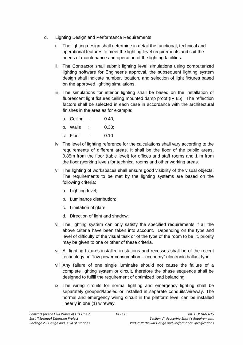
Contract for the Civil Works of LRT Line 2 VI - 115 BID DOCUMENTS East (Masinag) Extension Project Section VI. Procuring Entity’s Requirements Package 2 – Design and Build of Stations Part 2: Particular Design and Performance Specifications
d. Lighting Design and Performance Requirements
i. The lighting design shall determine in detail the functional, technical and
operational features to meet the lighting level requirements and suit the
needs of maintenance and operation of the lighting facilities.
ii. The Contractor shall submit lighting level simulations using computerized
lighting software for Engineer’s approval, the subsequent lighting system
design shall indicate number, location, and selection of light fixtures based
on the approved lighting simulations.
iii. The simulations for interior lighting shall be based on the installation of
fluorescent light fixtures ceiling mounted damp proof (IP 65). The reflection
factors shall be selected in each case in accordance with the architectural
finishes in the area as for example:
a. Ceiling : 0.40,
b. Walls : 0.30;
c. Floor : 0.10
iv. The level of lighting reference for the calculations shall vary according to the
requirements of different areas. It shall be the floor of the public areas,
0.85m from the floor (table level) for offices and staff rooms and 1 m from
the floor (working level) for technical rooms and other working areas.
v. The lighting of workspaces shall ensure good visibility of the visual objects.
The requirements to be met by the lighting systems are based on the
following criteria:
a. Lighting level;
b. Luminance distribution;
c. Limitation of glare;
d. Direction of light and shadow;
vi. The lighting system can only satisfy the specified requirements if all the
above criteria have been taken into account. Depending on the type and
level of difficulty of the visual task or of the type of the room to be lit, priority
may be given to one or other of these criteria.
vii. All lighting fixtures installed in stations and recesses shall be of the recent
technology on “low power consumption – economy” electronic ballast type.
viii. Any failure of one single luminaire should not cause the failure of a
complete lighting system or circuit, therefore the phase sequence shall be
designed to fulfill the requirement of optimized load balancing.
ix. The wiring circuits for normal lighting and emergency lighting shall be
separately grouped/labeled or installed in separate conduits/wireway. The
normal and emergency wiring circuit in the platform level can be installed
linearly in one (1) wireway.

Contract for the Civil Works of LRT Line 2 VI - 116 BID DOCUMENTS East (Masinag) Extension Project Section VI. Procuring Entity’s Requirements Package 2 – Design and Build of Stations Part 2: Particular Design and Performance Specifications
x. Lighting fixtures for platforms/stairs shall have IP65 protection and IEC
certified, Unbreakable polycarbonate compliance with ASTM D 256,
unbreakable clear polycarbonate diffuser, waterproof, shock resistant, UV
stabilized to prevent yellowing, smooth exterior surface and with internal
prismatic reading for efficient luminance, stainless clips.
xi. All materials to be used for the lighting project shall be brand new. The
Engineer may require the contractor to demonstrate/compare different
lighting lamps system for power consumption economy.
The parts of the lighting system should be easily reachable with a regular
ladder for maintenance reasons and easy to be maintained. General
accessibility and replacement of lamps without tools shall be possible.
e. Lighting Levels
i. The rated luminance assigned to a particular type of room, location or
activity is based on the difficulty of the visual task and assumes that the
effect of this luminance on the visual performance shall not be adversely
influenced by such factors as direct glare, reflected glare and contrast
reduction/shadow.
ii. The main concern with regards to civil work interfaces is the ceiling
structure and surface condition of the areas to be illuminated for existing
areas. The following Table G-1 specifies the required lighting levels:
Table G–1 Required Lighting Levels
Room
No. Station Area
Illumination
Level in Lux
(average)
Position of
Measurement
1.0 Public Areas
1.1
Exit to streets including external part of staircases + escalators
normal 150 Floor
1.2 Escalators and stairs (indoor part)
normal 250 Floor
1.3 Top and bottom landing of escalators and stairs
normal 250 Floor
1.4 Emergency Exits normal 250 Floor
1.5 Concourse-general (mezzanine)
normal 150 Floor
1.6 Platforms normal 150 Floor
1.7 Accesses to platforms normal 150 Floor
1.8 Corridors - Exits from platforms
normal 150 Floor
1.9 Lifts (Elevators) normal 150 Floor

Contract for the Civil Works of LRT Line 2 VI - 117 BID DOCUMENTS East (Masinag) Extension Project Section VI. Procuring Entity’s Requirements Package 2 – Design and Build of Stations Part 2: Particular Design and Performance Specifications
Room
No. Station Area
Illumination
Level in Lux
(average)
Position of
Measurement
2.0 Staff Areas
2.1 Ticket Booth normal 400 Floor
2.2 Passenger Assistance Booth normal 400 0.85 from floor
3.0
3.1
3.2
3.3
3.4
Technical Areas
Signaling Local Control
Room
Battery Room
Electrical Room
Substation
Normal
normal
normal
normal
400
150
150
15
Floor
Floor
Floor
Floor
f. Station Lighting Design Requirements
i. Station public areas lighting shall be achieved mostly but not limited to
fluorescent luminaries depending on the limitation of using fluorescent
luminaries as the situation requires. The lighting color shall be daylight.
ii. High Bay luminaires using High Intensity Discharge lamps shall be used for
high ceiling areas.
iii. Luminaires shall be positioned so that they do not obscure signs or train
indicators. Especially for corridors, staircases, and entrances/exits, the
luminaires shall be positioned so that passengers do not cause shadows to
obscure staircase landings or corridor junctions/turns.
iv. Outdoor lighting for station entrances shall be mounted on stations’
columns/walls or roof slab and shall provide illumination to the station
entrances, to illuminated signs and to adjacent walkways. As described
above it shall be controlled by photoelectric switches.
v. The lighting design in coordination with other system shall also coordinate
with Telecom , Signaling, and Safety groups with regards to alignment with
PA speakers, clocks, CCTV cameras, signal lights, safety signs, station
names, and platform mirrors. The lighting fixtures/wireway for stations
public areas shall be of the linear type, in coordination with the architectural
elements, unless otherwise specified. These lighting fixtures shall have the
following characteristics:
a. Serving as cable raceways for lighting cables and other future cables, in
accordance with the aesthetic requirements for non–existence of visible
cabling in public areas,

Contract for the Civil Works of LRT Line 2 VI - 118 BID DOCUMENTS East (Masinag) Extension Project Section VI. Procuring Entity’s Requirements Package 2 – Design and Build of Stations Part 2: Particular Design and Performance Specifications
b. The wireway/raceway shall be hot dip galvanized and the installation
design of all fixtures shall be that it can withstand the wind velocity
caused by typhoons, and
c. It shall be ensured that proper cable operation and life expectancy are
not adversely affected by temperature effects from the lighting and the
cabling itself.
vi. The external lighting design of the ticket booths on the stations shall follow
the concept design of the newly constructed booths or as approved by the
Engineer.
vii. For stations with limited platform space due to the presence of the electrical
room and relay room and when a linear type fluorescent luminaries
installation design is not possible, other types of lighting fixtures suitable to
the required condition can be used upon the approval of the Engineer.
g. Switches and Control
i. Lighting switches for public area lighting shall be installed in locations
accessible to the station staff. The switches shall be in an enclosure with
key made of materials suitable to protect the switches from physical and
environmental damages. All other station areas (offices, staff and technical
rooms) as well as other technical rooms in shafts, recesses, etc. shall have
local wall mounted switches.
ii. Switches of light box shall be 10A, 220V, quiet–matic type with stainless
cover.
iii. Switching of lighting fixtures at the platform level shall be alternate or
staggered.
4.6.3 Requirements for Materials and Fittings for Power Supply System
All equipment and materials supplied as part of the Station Power and Lighting
Works shall comply with the requirements of this section. These requirements shall
be taken to be generally applicable in accordance with good practice, and they shall
not relieve the Contractor from ensuring that all materials and equipment
incorporated in the Works are suitable for their intended purposes and environments.
a. Wiring Devices and Equipment
i. Snap Switches
Switches shall be heavy duty, rated 10A, 240V AC quite-type. All exposed
materials subject to corrosion shall be stainless steel i.e. cover plates,
mounting screws, etc.
ii. Receptacles
Provide heavy-duty, grounding type duplex receptacles. Ratings shall be
15A, 2P, 3W, 240V. Bodies shall be of ivory thermosetting plastic supported
on a metal mounting strap. Wiring terminals shall be of the screw type.
Connect grounding pole to the mounting strap. All exposed materials

Contract for the Civil Works of LRT Line 2 VI - 119 BID DOCUMENTS East (Masinag) Extension Project Section VI. Procuring Entity’s Requirements Package 2 – Design and Build of Stations Part 2: Particular Design and Performance Specifications
subject to corrosion shall be stainless steel i.e. cover plates, mounting
screws, etc.
iii. Weatherproof Receptacles
Provide in a cast aluminum box with gasketed, weatherproof, cast-metal
cover plate and gasketed cap over each receptacle opening. The cap(s)
shall be provided with a spring-hinged flap.
iv. Air–Conditioning Unit Outlets
Rating shall be 30A, 2P, 3W, 240V grounding type. All exposed materials
subject to corrosion shall be stainless steel i.e. cover plates, mounting
screws, etc.
v. Disconnect Switches NEMA KS1
Switches serving as motor–disconnect mean shall be horsepower rated and
heavy duty type. NEMA 4X if installed outdoors.
vi. Enclosed Circuit Breaker
UL 489. Individual molded case circuit breaker shall be thermal magnetic
type. Voltage, continuous current rating, number of poles, interrupting
capacity shall be suited to application. Nema 4X if installed outdoors.
vii. High Efficiency Single-Phase Motors
Single–phase fractional–horsepower alternating–current motors shall be
high efficiency types corresponding to the applications listed in NEMA MG
11.
viii. High Efficiency Polyphase Motors
Polyphase motors shall be selected based on high efficiency characteristics
relative to the applications as listed in NEMA MG 10.
ix. Motor Controllers
All controllers shall have thermal overload protection in each phase.
Magnetic–type motor controllers shall have under voltage protection when
used with momentary–contact pushbutton stations or switches and shall
have under voltage release when used with maintained–contact pushbutton
stations or switches. When used with a pressure, float, or similar
automatic–type or maintained–contact switch, the controller shall have a
hand–off–automatic selector switch. Connections to the selector switch
shall be such that only the normal automatic regulatory control devices will
be bypassed when the switch is in the “hand” position. All safety control
devices, such as low and high pressure cutouts, high temperature cutouts,
and motor overload protective devices, shall be connected in the motor
control circuit in both the “hand” and the “automatic” positions. Control
circuit connections to any hand–off–automatic selector switch or to more
than one automatic regulatory control device shall be made in accordance
with an indicated, or a manufacturer’s approved, wiring diagram. The

Contract for the Civil Works of LRT Line 2 VI - 120 BID DOCUMENTS East (Masinag) Extension Project Section VI. Procuring Entity’s Requirements Package 2 – Design and Build of Stations Part 2: Particular Design and Performance Specifications
selector switch shall have means for locking in any position. For each motor
not in sight of the controller, the controller disconnecting means shall be
capable of being locked in the open position or a manually operated, non–
fused switch which will disconnect the motor from the source of supply shall
be placed within sight of the motor location. Overload protective devices
shall give adequate protection to the motor windings, be of the thermal
inverse–time–limit type, and include a manual–reset type pushbutton on the
outside of the motor controller case. The cover of a combination motor
controller and manual switch or circuit breaker shall be interlocked with the
operating handle of the switch or circuit breaker so that the cover cannot be
opened unless the handle of the switch or circuit breaker is in the off
position.
x. Panelboards
Panelboards for use as service disconnecting means shall be circuit
breaker equipped. Panelboards shall be made from steel sheet not less
than 2.0 mm in thickness. Design shall be such that any individual breaker
can be removed without disturbing adjacent units or without loosening or
removing supplemental insulation supplied as a means of obtaining
clearances as required by UL. Where "space only" is indicated, make
provisions for the future installation of a breaker sized as indicated. All
panelboard locks included in the project shall be keyed alike. Directories
shall be typed to indicate load served by each circuit and mounted in a
holder behind transparent protective covering.
xi. Panelboard Buses
Provide UL listed bus current ratings as indicated. Support bus bars on
bases independent of the circuit breakers. Main buses and back pans shall
be designed so that breakers may be changed without machining, drilling,
or tapping. Provide an isolated neutral bus in each panel for connection of
circuit neutral conductors. Provide a separate ground bus marked with a
green and yellow stripes along its front and bonded to the steel cabinet for
connecting grounding conductors.
xii. Circuit Breakers
UL 489, bolt–on, thermal magnetic-type having a minimum short circuit
current rating equal to the short-circuit current rating of the panelboardin
which the circuit breaker shall be mounted. Breaker terminals shall be UL
listed as suitable for type of conductor provided.
xiii. Multi–pole Breakers
Provide common–trip type with a single toggle/operating handle. Breaker
design shall be such that an overload in one pole automatically causes all
poles to open. Maintain phase sequence throughout each panel so that any
three adjacent breaker poles are connected to Phases A, B, and C,
respectively.

Contract for the Civil Works of LRT Line 2 VI - 121 BID DOCUMENTS East (Masinag) Extension Project Section VI. Procuring Entity’s Requirements Package 2 – Design and Build of Stations Part 2: Particular Design and Performance Specifications
xiv. Transformers
General purpose, dry–type, self–cooled, ventilated or unventilated. Provide
transformers in NEMA 2 enclosure. Transformer shall have 220 degrees C
insulation system for transformers 15 kVA and greater, and shall have 180
degrees C insulation for transformers rated 10 kVA and less, with
temperature rise not exceeding 115 degrees C under full-rated load in
maximum ambient of 40 degrees C. Transformer of 115 degrees C
temperature rise shall be capable of carrying continuously 115 percent of
nameplate kVA without exceeding insulation rating. Transformers shall be
quiet type with maximum sound level at least 3 decibels less than NEMA
standard level for transformer ratings indicated.
b. Wiring Methods
i. All apparatus shall have adequate provision for the entry and termination of
all associated power and auxiliary cables and, where necessary, the
Contractor shall provide for this purpose a suitable terminal box mounted
directly upon and immediately adjacent to each item involving such
interconnection.
ii. All wires between the terminals of two items of equipment shall be given
unique wire numbers according to an approved system. A wire number
shall not change solely by virtue of passing through.
iii. Identification markers shall be fitted to all wires and multicore cables tails
within enclosures in accordance with the diagram for the apparatus
concerned. Cable and core markers shall be of insulating material, colored
according to the Contractor’s system, with a glossy finish to prevent
adhesion of dirt. They shall be legible and durably marked and shall not be
affected by oil or moisture. Numbers shall not be duplicated unless the
corresponding wires are directly in series or parallel.
iv. Rigid Steel Conduits (RSC) or Galvanized Cable Tray shall be used for all
feeder runs and risers and in general all raceway for power and lighting, as
the case may be.
v. Cable tray shall be ladder type (with or without cover depending on the
approval of the Engineer). Trays shall be constructed steel that has been
zinc-coated after fabrication. Trays shall be heavy duty type and shall
include splice and end plates, dropouts, and miscellaneous hardware.
Edges, fittings, and hardware shall be finished free from burrs and sharp
edges. Fittings shall have not less than load-carrying ability of straight tray
sections and shall have manufacturer's minimum standard radius. Radius of
bends shall be 305 mm.
vi. Flexible metal conduit shall be used for connection from ceiling to lighting
fixtures and where RSC is impractical under such conditions where
equipment is prone to vibration or thermal expansion. Flexible metal
conduits shall be liquid tight, with a flexible steel core and extruded liquid
tight neoprene jacket overall.

Contract for the Civil Works of LRT Line 2 VI - 122 BID DOCUMENTS East (Masinag) Extension Project Section VI. Procuring Entity’s Requirements Package 2 – Design and Build of Stations Part 2: Particular Design and Performance Specifications
vii. Conductors are copper unless otherwise specified. Insulated conductor
manufactured more than 6 months before delivery to the job site shall not
be used. Material specifications, i.e., brand, size, insulation type, voltage,
etc., shall be clearly printed at the insulation.
viii. 600 Volt Wires and Cables: Provide wires with THW designation. Only wires
with "W" in the type designation shall be used in wet or damp locations.
Conductor sizes indicated by square millimeter (mm2) for copper
conductors.
ix. Conductors: Conductors 5.5 mm2 and smaller shall be solid, and those 8
mm² and larger shall be stranded.
x. Minimum Conductor Sizes: Minimum size for branch circuits shall be 3.5
mm². For Class 1 remote-control and signal circuits, it shall be 2.0 mm²; and
for Class 2 low–energy remote–control and signal circuits, 2.0 mm².
xi. Color Coding: Provide color coding
a. For all service, feeder, branch, control, and signaling circuit conductors.
b. For grounding conductor, color shall be green with yellow stripes. For
neutral, color shall be white, except where neutrals of more than one
system are installed in same raceway or box, the other neutral shall be
white with a colored (not green) stripes.
c. Junction Boxes and Pull Boxes (With Volume Greater than 100 cu.
inches): hot-dip, zinc coated steel sheet, gauge # 14.
xii. Splices and Termination Components
a. Connectors for wires 5.5 mm2 and smaller shall be insulated pressure–
type (twist-on-splicing connector). Provide solderless terminal lugs on
stranded conductors. ii. Underground Conduit (Other Than Service
Entrance): Rigid Steel conduit with coal tar coatings.
b. Conduit in Floor Slabs: Rigid steel conduit.
xiii. Conduit Installation
a. Unless indicated otherwise, conceal conduit within finished walls,
ceilings, and floors. Keep conduit at least 150 mm away from parallel
runs of hot pipes.
b. Where conduits cross a seismic joint, approved flexible conduit shall be
used. It shall be provided with adequate seals to satisfactorily plug the
conduits on the warm side of the wall to prevent condensation within the
conduit.
c. Where conduits rise through floor slabs, the curved portion of bends
shall not be visible above the finish slab.
d. Support conduit/wireway by wall brackets, hangers, or ceiling trapeze.

Contract for the Civil Works of LRT Line 2 VI - 123 BID DOCUMENTS East (Masinag) Extension Project Section VI. Procuring Entity’s Requirements Package 2 – Design and Build of Stations Part 2: Particular Design and Performance Specifications
e. Make changes in direction of runs with symmetrical bends or cast–metal
fittings
f. Conduit bends shall not contain more than two 90° bends or the
equivalent. Provide pull or junction boxes where necessary to comply
with these requirements.
g. Conduit Installed in Concrete Floor Slabs shall be located so as not to
adversely affect the structural, strength of the slabs.
h. Sealing of Cable Holes through Floors and Walls – After completion of
cabling, all penetrations through floors and walls shall be sealed
employing fire–resisting materials
i. Fasten conduits to sheet metal boxes and cabinets with two locknuts
where insulated bushings are used, and where bushings cannot be
brought into firm contact with the box; otherwise, use at least a single
locknut and bushing.
k. Flexible connections of short length of a maximum of 1.8 meters shall
be provided for recessed and semi–recessed lighting fixtures; for
equipment subject to vibration, noise transmission, or movement; and
for all motors. Liquid–tight flexible conduit shall be used in wet
locations. A separate ground conductor shall be provided across
flexible connections.
xv. Boxes, Outlets, and Supports:
a. Provide boxes in the wiring or raceway systems wherever required for
pulling of wires, making connections, and mounting of devices or fixtures.
Boxes for metallic raceways shall be of the cast–metal hub type when
located in normally wet locations, when surface mounted on outside of
exterior surfaces, when installed exposed up to 2 meters above interior
floors and walkways. Boxes in other locations shall be sheet steel
(minimum gauge #16 hot–dip, zinc coated), except that aluminum boxes
may be used with aluminum conduit, and nonmetallic boxes may be used
with nonmetallic sheathed cable conduit system. Each box shall have the
volume required by the Code for the number of conductors enclosed in the
box.
b. Threaded studs driven in by powder charge and provided with lock washers
and nuts or nail–type nylon anchors may be used in lieu of wood screws,
expansion shield or machine screws
c. Boxes for use with raceway systems shall not be less than 38 mm deep,
except where shallower boxes required by structural conditions are
approved. Boxes for other than lighting–fixture outlets shall be not less than
100 mm width, except that 100 mm by 50 mm boxes may be used where
only one raceway enters the outlet.
d. Pull Boxes shall be hot–dip, zinc coated steel sheet minimum gauge # 16,
except where cast–metal boxes are required in locations specified above.

Contract for the Civil Works of LRT Line 2 VI - 124 BID DOCUMENTS East (Masinag) Extension Project Section VI. Procuring Entity’s Requirements Package 2 – Design and Build of Stations Part 2: Particular Design and Performance Specifications
Furnish boxes with stainless steel screw-fastened covers. Where several
feeders pass through a common pull box, tag the feeders to indicate clearly
the electrical characteristics, circuit number, and panel designation. All
exposed materials subject to corrosion shall be stainless steel, i.e., cover
plates, mounting screws, bolts and nuts, etc.
xvi Extension rings may be used only on existing boxes in concealed conduit
systems where wall is furred out for new finish.
xvii. Mounting Heights
Mount panelboards, circuit breakers, and disconnecting switches such that the
height of the operating handle at its highest position will not exceed 2 meters
from the floor. Mount lighting switches 1.4 meters above finished floor,
receptacles 300 mm above finished floor, and other devices as indicated.
Measure mounting heights of wiring devices and outlets to the center of device
or outlet.
xviii. Conductor Identification
Provide conductor identification within each enclosure where a tap, splice, or
termination is made. For conductors 14 mm2 and smaller, color–coding shall
be by factory–applied color–impregnated insulation. For conductors 22 mm²
and larger, color–coding shall be by plastic–coated self–sticking markers,
colored nylon cable ties and plates, or heat–shrink type sleeves. Identify
control circuit terminations.
xix. Splices
Make splices in accessible locations. Make splices in conductors 5.5 mm² and
smaller with an insulated pressure type connector. Make splices in conductors
8 mm² and larger with a solderless connector and cover with an insulation
material equivalent to the conductor insulation.
xx. Covers and Device Plates
Install with all four edges in continuous contact with finished wall surfaces
without the use of mats or similar devices.
xxi. Grounding and Bonding
Ground all exposed non–current–carrying metallic part of electrical equipment,
metallic raceway systems, grounding conductor in nonmetallic raceways, and
neutral conductor of wiring systems.
xxii. Grounding Conductor
Provide an insulated, green with yellow stripes equipment grounding conductor
in all feeder and branch circuits. This conductor shall be separated from the
electrical system neutral conductor.

Contract for the Civil Works of LRT Line 2 VI - 125 BID DOCUMENTS East (Masinag) Extension Project Section VI. Procuring Entity’s Requirements Package 2 – Design and Build of Stations Part 2: Particular Design and Performance Specifications
5.0 FIRE PROTECTION SYSTEM
5.1 DESIGN REQUIREMENTS
5.1.1 General
a. The design of a station shall include the following:
Fire prevention measures
Fire control measures
Fire detection systems
Means of escape
Access for firemen
Means of firefighting
b. All aspects of fire prevention and control will require close liaison between the
Contractor and the firefighting authority and final proposals shall be subject to
the approval of the relevant authorities.
5.1.2 Scope of Work
The new Emerald and Masinag Stations shall have Fire Detection and Alarm System,
FDAS and Fire Protection System and Equipment.
The Fire Detection and Alarm System shall consist of Fire Alarm Control Panel
(FACP), Bells/horns, Smoke Detectors, Heat Detectors, and Manual Pull Stations.
The Fire Protection System shall consist of:
a. Wet–Type Fire Protection System which includes wet pipes and hose reel
(WPH), wet pipe and automatic sprinklers (WPS), and water supply system
(complete with piping, water tanks, pumps, and pump controllers).
b. Portable Fire Extinguishers using dry chemicals, CO2, and clean agent, totaling
not less than eighty (80) in quantity.
In Emerald and Masinag Stations, portable fire extinguishers shall be provided as
required in locations indicated or as directed by the Engineer.
5.1.3 Fire Prevention
a. Fire prevention measures shall be designed and implemented to minimize the
risk of outbreak of fire by appropriate choice, location and installation of
materials and equipment.
b. In station planning terms, potential sources of fire can be reduced by:
The use of non–combustible or smoke retardant materials where possible
provision of layouts which permit ease of maintenance for equipment and
cleaning of the station
Provision of special storage spaces for combustible materials such as paint

Contract for the Civil Works of LRT Line 2 VI - 126 BID DOCUMENTS East (Masinag) Extension Project Section VI. Procuring Entity’s Requirements Package 2 – Design and Build of Stations Part 2: Particular Design and Performance Specifications
and oil
Prohibition of gas based cooking facilities in the staff areas.
Prohibition of smoking
Provision of cigarette and litter bins
General good housekeeping
Staff training and procedures
5.1.4 Fire Control
a. Control of the spread of fire and smoke shall be by achieved by
compartmentalization of fire risk areas, smoke extraction and smoke
containment.
b. Compartmentalization is aimed at limiting the extent of a fire. A compartment
consists of a portion of the station or other structure which is separated from
adjoining portions by walls, floors and/or doors. Any opening must be capable
of being sealed in the event of a fire, e.g. duct openings sealed with fire
dampers. Fire resistance periods (FRPS) shall be selected for spaces
according to their degree of fire load and the degree of protection required for
life safety, security of the system and the preservation of adjoining areas.
c. Openings, including ducts and passages between LRT property and any
adjoining structure which allows free access into the LRT property shall be
protected by fire doors, fire shutters, fire dampers, etc., as appropriate.
5.1.5 Fire Detection
a. The fire alarm and detection system for each station shall comprise automatic
smoke/heat detectors, and break glass units interconnected with the local fire
alarm panel. The panel shall be located in the Station Control Room/Ticket
Office together with a mimic panel indicating fire status on a zone by zone
basis.
b. Upon receipt of a fire signal, the fire alarm panel shall operate audible and
visual alarms within the staff areas only. The warning for the public shall be
implemented by staff via the public address system.
c. The automatic fire detectors of the smoke and heat sensitive type shall be
installed in the staff offices, traction substation, electrical rooms, and lift
machine rooms.
5.1.6 Means of Escape
a. Design for evacuation of passengers from stations is described elsewhere.
Standards quoted here apply to the non-public areas of offices and plant-
rooms. Non-public areas of stations are accessible only to LRT Staff and
usually only in small numbers. These areas shall be compartmented and fully
covered by the fire detection and alarm system.
b. As with the public areas of a station, escape from all non-public areas shall be

Contract for the Civil Works of LRT Line 2 VI - 127 BID DOCUMENTS East (Masinag) Extension Project Section VI. Procuring Entity’s Requirements Package 2 – Design and Build of Stations Part 2: Particular Design and Performance Specifications
possible to a place of safety. For staff-only areas a place of safety shall be an
area outside the compartmented area of the fire. Staff will be trained in fire-
fighting procedures and may not require total escape from the station in a
contained fire situation.
c. The travel distance from any point in non–public areas to an area of relative
safety shall depend upon whether alternative means of escape are available.
Where only one direction of escape is available travel distances shall be less
than 20m. Where escape is possible in more than one direction the travel
distance shall be less than 40m Escape routes from plant areas may include
manhole or ladder access.
5.1.7 Access for Firemen
a. Access for firemen shall be provided by:
A designated route from an Access Point to the Station Control Room
A designated route from an Access point to all levels of the station
In some station designs, these protected routes may be the same for part of
their lengths
The Access Points shall be at street level in the open air, close to a
designated space for off-road parking for two firemen's vehicles.
b. Additional stairways may be identified for the use of fire fighters, where access
from the Firemen’s Access Stairway to certain parts of the building is obstructed
by tracks, or in other ways. This stair shall serve all principal levels, shall be
pressurized, and shall be fitted with sprinkler system and a fire-fighting hydrant.
The locations of these stairs will be determined on a case by case basis.
Wherever possible, access will be from street level.
5.1.8 Fire Hydrant and Hose Reel System
a. All works shall be performed in accordance with all applicable municipal codes
and laws and regulations issued by Government Agencies or Authorities. The
latest standards, codes and regulations published shall be used.
b. The proposed fire protection system shall comprise the following:
Fire hydrant and hose reel system for the public areas.
Portable fire extinguishers for the electrical rooms, pump rooms, staff
offices and public areas.
c. A fire hydrant and hose reel system shall be provided at each station to protect
plant, occupants and public areas as a first means of fighting the fire whilst
awaiting the arrival of the local fire authority.
i. Water Supply
Firefighting water supply shall be fed from a storage tank and duplicated
pump set.
The water tank shall be sized for a minimum of 30 minute storage

Contract for the Civil Works of LRT Line 2 VI - 128 BID DOCUMENTS East (Masinag) Extension Project Section VI. Procuring Entity’s Requirements Package 2 – Design and Build of Stations Part 2: Particular Design and Performance Specifications
capacity.
Fire department connection to a stand pipe shall also be provided at
ground floor level as a secondary source of water supply.
A wet stand pipe system shall supply water to the fire hose cabinets
located at accessible locations within the station public areas.
ii. Fire Hose Cabinet
The fire hose cabinet shall be equipped with a 40mm diameter, 30m long
flexible hose with nozzle, a 65mm diameter angle valve with coupling and a
4.5 kg capacity multi–purpose portable dry chemical fire extinguisher.
iii. Water Pressure
A diesel engine driven horizontal spindle fire pump and motor driven jockey
pump, complete with accessories shall be housed in a pump room located
adjacent to the water tank. The jockey pump will keep the system flooded
and pressurised at all times.
5.1.9 Fire–Resisting Construction
The main structural elements shall be designed to have a Fire Resistance Period
(FRP) not less than that specified below.
Fire Resistance Period (hours)
Structural Elements
Underground structures, and other structures incorporating development above
Surface and overhead structures, without development above
Roof Structure - 0 *
Stations 4 2
Substations 4 2
Cable tunnels 4 2
Ventilation Buildings 4 2
Ancillary Buildings 4 2
Staircases 4 2
* where it can be shown that the structural elements supporting the roof can survive
the design fire without undue risk of collapse.
5.1.10 Compartmentalization of Station Areas
a. Lifts
Lifts between floors in public areas may consist of glass cars with glazed doors
and glass lift shafts. Such shafts shall be protected by concealed smoke
reservoir bulkheads in suspended ceilings. Where lifts pass through floors that
are not protected by smoke extraction they shall be separated from that floor by
a minimum of one–hour FRP separation.

Contract for the Civil Works of LRT Line 2 VI - 129 BID DOCUMENTS East (Masinag) Extension Project Section VI. Procuring Entity’s Requirements Package 2 – Design and Build of Stations Part 2: Particular Design and Performance Specifications
Non–glazed lifts in staff areas may have glazed doors for security purposes but
shall be separated from the surrounding floor by a smoke lobby with one hour
FRP walls and doors.
b. Offices and Plant Rooms
Station Control Room glazing shall be protected by a two hour FRP fire shutter.
All offices and plant rooms shall be separated from the public circulation spaces
by two hour FRP separation. Each plant room shall be a separate
compartment. In plant rooms roller shutters may be used, in addition to fire–
rated personnel pass doors. Such shutters shall normally be closed and be fire
rated to the same FRP as the wall in which they are contained. The Fire
Resistance Periods to be used for sub–compartmentalization shall be not less
than specified below. Offices and staff areas shall be separated from the public
spaces, but shall not be subject to sub–compartmentalization.
5.1.11 Separation from Property Developments
The structural elements supporting, and the compartment walls and floors separating
a station from a Property Development Area shall have four–hour Fire Resistance
Period. Where necessary this separation may be achieved by fire shutters. If a
shutter comes down over the front of a shop or otherwise blocks an Escape Route,
an alternative means of escape shall be provided.
5.1.12 Fire Resistant Period for Sub–Compartmentalization
In the accompanying Table
Note: 1. The FRP requirements in the Table are for general application only.
With Individual FRP requirements considered on a case by case
basis.
2. * Fire separation where adjoining staircases shall be 4 hours FRP
Fire Resistance Period (hours)
Compartments
Underground structures, and other structures incorporating development above
Surface and overhead structures, without development above
Substations 4* 2*
Station Substations (including transformer rooms)
2* 2*
Ventilation Plant rooms 2 1
Electrical Equipment Rooms (excluding transformer rooms)
2 1
Escalator machine Rooms 2 1
Signalling Equipment Rooms 2 1
Battery Rooms 2* 2*

Contract for the Civil Works of LRT Line 2 VI - 130 BID DOCUMENTS East (Masinag) Extension Project Section VI. Procuring Entity’s Requirements Package 2 – Design and Build of Stations Part 2: Particular Design and Performance Specifications
Fire Resistance Period (hours)
Compartments
Underground structures, and other structures incorporating development above
Surface and overhead structures, without development above
Rectifier Transformer Room 2* 2*
Rectifier transformer bay (Outdoor) N/A N/A
Control Rooms (including Computer rooms)
2 2
Telecommunication Rooms 2 1
Ventilation Shafts 2 -
Under-platform Cable ducts 2 1
Exhaust Ducts 1 1
Protected Staircases 4 2
Store Rooms 2 1
Refuse Rooms 2 1
Station Facilities, Offices, and other Rooms in Staff Areas
1 1
Pump Rooms 4 2
Standby Diesel generator Rooms 4 2
Fuel Storage tank Rooms 4 2
All other Areas 1 1
5.1.13 Fire Detection and Alarm System
The FDAS Contractor shall take full responsibility for Fire Detection and Alarm
System including detailed design of the works. The work shall include the following
materials to complete Fire Detection and Alarm System such as Fire Alarm Control
Panel, Bells/Horns, Smoke Detectors, Heat Detectors, Manual Pull Stations, Cables
and conduits/wireways, and all accessories and fittings, hangers/supports, etc.
The following are the scope of works to complete the Fire Detection and Alarm
System including the Fire Alarm Control Panel:
1. Provision of power supply to Fire Protection System, wherever required,
2. All other items incidental for the proper completion of the installation works,
3. Coordination with other trades that interfaces with their works,

Contract for the Civil Works of LRT Line 2 VI - 131 BID DOCUMENTS East (Masinag) Extension Project Section VI. Procuring Entity’s Requirements Package 2 – Design and Build of Stations Part 2: Particular Design and Performance Specifications
Fire detection and alarm system for all electrical and equipment rooms including
traction substations shall not be a part of this Contract but in Fire Protection System
and Equipment.
5.1.14 Fire Protection System and Equipment
The Fire Protection System and Equipment Contractor shall take full responsibility for
Fire Protection System and Equipment including detailed design.
All works for complete Fire Protection System and Equipment including wet pipe and
hose reel (WPH) wet pipe and automatic sprinkler (WPS) and water tanks, pumps
and pump controllers are all fire extinguishers and all accessories and fittings,
hangers/supports, etc. which are necessary to complete the project. Any room/area
not covered in Fire Protection System works shall be covered by the Wet Type
System and shall be provided in the Fire Detection and Alarm System contractor.
1. Provision of power supply to Fire Protection System, wherever required,
2. Coordination with other trade of work/contractor,
3. Coordination with companies/offices including acquisition of permits related to the
services,
The tables below are showing rooms and locations in the station where one of the
system will be provided.
DRY TYPE SYSTEM
Emerald Masinag
Concourse FDAS FPSE FDAS FPSE
Pump Room
DC DC
Public Area
Paid DC DC
Unpaid
Technical
Rooms
Substation CO2 CO2
Electrical CO2 CO2
Telecom CA CA
Signaling CA CA
Ticket Offices
Ticket
Vending Booth
DC
DC

Contract for the Civil Works of LRT Line 2 VI - 132 BID DOCUMENTS East (Masinag) Extension Project Section VI. Procuring Entity’s Requirements Package 2 – Design and Build of Stations Part 2: Particular Design and Performance Specifications
Emerald Masinag
Passenger Assistance
Booth
DC
DC
Platform
Public Area
Paid DC DC
Unpaid
Technical
Rooms
Transformer
Room
Electrical
Telecom
Signaling
Ticket Offices
Ticket
Vending Booth
Passenger Assistance
Booth
Legend:
FDAS – Fire Detection and Alarm System DC – Dry Chemical, Portable
FE – Fire Extinguisher, Portable CO2 – Carbon Dioxide, Portable
- with corresponding equipment CA – Clean Agent, Portable
WET TYPE SYSTEM (PACKAGE B)
Public Areas Wet Type System
1. Station Entrance Wet type + Hose reel
2. Stairs/Escalators Wet type + Sprinkler
3. Concourse Wet type + Hose reel
4. Platforms Wet type + Hose reel
5. Public WC Wet type + Hose reel
6. Space for Kiosks or shops Wet type + Hose reel
7. Access to Platform Level Wet type + Hose reel

Contract for the Civil Works of LRT Line 2 VI - 133 BID DOCUMENTS East (Masinag) Extension Project Section VI. Procuring Entity’s Requirements Package 2 – Design and Build of Stations Part 2: Particular Design and Performance Specifications
Public Areas Wet Type System
Staff Areas
1. Staff WC Wet type + Hose reel
2. Passage for Staff Areas Wet type + Hose reel
3. Cleaners Room Wet type + Hose reel
4. Terminal Train Staff Area Wet type + Hose reel
Technical Areas
1. Corridor for Technical Rooms Wet type + Hose reel
2. Escalators Truss Work Wet type + Sprinkler
3. Elevator Wet type + Sprinkler
5.1.15 Reference Standards
American Society for Testing and Materials (ASTM) Publications:
a. 53–80 Pipe, Steel, Black and Hot–Dipped Zinc–Coated Welded and Seamless
120–80 Pipe, Steel, Black and Hot–Dipped Zinc–Coated (Galvanized) Welded
and Seamless for Ordinary Uses
b. Factory Mutual System (FM) Publication: (1987) Approval Guide
c. National Fire Protection Association (NFPA) Publication:13–89 Sprinkler Systems
70–87 National Electrical Code
d. Underwriter’s Laboratories, Inc. (UL) Publications: 262–80 Gate Valves for Fire
Protection Service

Contract for the Civil Works of LRT Line 2 VI - 134 BID DOCUMENTS East (Masinag) Extension Project Section VI. Procuring Entity’s Requirements Package 2 – Design and Build of Stations Part 2: Particular Design and Performance Specifications
5.2 AUTOMATIC WET–PIPE FIRE EXTINGUISHING SYSTEM
5.2.1 General
The work includes the design new automatic wet–pipe fire extinguishing system and
standpipe system to afford complete fire protection coverage for the Proposed LRT
Line 2 Stations of East (Masinag) Extension Project. The sprinkler protection shall
provide protection for the Mezzanine, PHA and Platform areas and standpipe system
for the entire stations.
5.2.2 Products
5.2.2.1 Sprinkler’s Head
Heads shall have nominal 12.5mm (0.50 inch) orifice. Temperature rating of the
sprinkler head shall be ordinary.
1. Pendent sprinkler shall be recessed, and with chrome plated finish. Escutcheon
plate shall have a painted white finish.
2. Upright sprinkler shall have a natural brass finish.
3. Horizontal sidewall shall have a chrome plated finish. Escutcheon plate shall
have painted white finish.
5.2.2.2 Sprinkler Reserve Cabinet
Provide metal cabinet (painted) with extra sprinkler heads and sprinkler head wrench
in the pump room. The number and types of extra sprinkler heads shall be as
follows:
No. of Sprinklers Extra Sprinklers
300 & less 24
300 to 1000 36
5.2.2.3 Fire Hose Cabinet
1. Hose cabinet shall have full glass door recessed on wall and shall able to
accommodate 38mm (1 ½ inch) hose rack unit with 30 meters (100 ft.) of hose
and portable fire extinguisher. Door and frame shall be made of aluminum.
2. Angel Hose Valve shall be 38mm (1 ½”) diameter and shall have rough brass
finish.
3. Hose shall be 38mm (1 ½”) diameter x 30 meters (100 feet) lined hose.
4. Nozzle shall be 38mm (1 ½”) diameter, shall have adjustable fog, straight stream
and shut-off features and shall have solid brass with satin finish and rubber
bumper. Fire, Potter and Reliable are acceptable brands.
5. Fire extinguisher shall be 9.5 liters (2 ½ gallon) pressurized water with a UL
rating of a 2A.
5.2.2.4 Pipe Sizes 65mm (2 ½ inches) and Larger
1. Steel Pipe: ASTM A 53, Schedule 40, (Standard), black steel pipe.
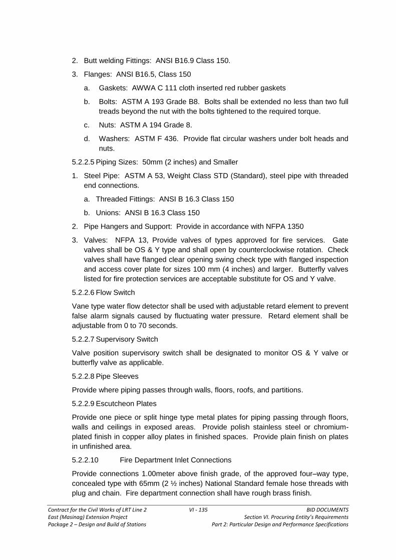
Contract for the Civil Works of LRT Line 2 VI - 135 BID DOCUMENTS East (Masinag) Extension Project Section VI. Procuring Entity’s Requirements Package 2 – Design and Build of Stations Part 2: Particular Design and Performance Specifications
2. Butt welding Fittings: ANSI B16.9 Class 150.
3. Flanges: ANSI B16.5, Class 150
a. Gaskets: AWWA C 111 cloth inserted red rubber gaskets
b. Bolts: ASTM A 193 Grade B8. Bolts shall be extended no less than two full
treads beyond the nut with the bolts tightened to the required torque.
c. Nuts: ASTM A 194 Grade 8.
d. Washers: ASTM F 436. Provide flat circular washers under bolt heads and
nuts.
5.2.2.5 Piping Sizes: 50mm (2 inches) and Smaller
1. Steel Pipe: ASTM A 53, Weight Class STD (Standard), steel pipe with threaded
end connections.
a. Threaded Fittings: ANSI B 16.3 Class 150
b. Unions: ANSI B 16.3 Class 150
2. Pipe Hangers and Support: Provide in accordance with NFPA 1350
3. Valves: NFPA 13, Provide valves of types approved for fire services. Gate
valves shall be OS & Y type and shall open by counterclockwise rotation. Check
valves shall have flanged clear opening swing check type with flanged inspection
and access cover plate for sizes 100 mm (4 inches) and larger. Butterfly valves
listed for fire protection services are acceptable substitute for OS and Y valve.
5.2.2.6 Flow Switch
Vane type water flow detector shall be used with adjustable retard element to prevent
false alarm signals caused by fluctuating water pressure. Retard element shall be
adjustable from 0 to 70 seconds.
5.2.2.7 Supervisory Switch
Valve position supervisory switch shall be designated to monitor OS & Y valve or
butterfly valve as applicable.
5.2.2.8 Pipe Sleeves
Provide where piping passes through walls, floors, roofs, and partitions.
5.2.2.9 Escutcheon Plates
Provide one piece or split hinge type metal plates for piping passing through floors,
walls and ceilings in exposed areas. Provide polish stainless steel or chromium-
plated finish in copper alloy plates in finished spaces. Provide plain finish on plates
in unfinished area.
5.2.2.10 Fire Department Inlet Connections
Provide connections 1.00meter above finish grade, of the approved four–way type,
concealed type with 65mm (2 ½ inches) National Standard female hose threads with
plug and chain. Fire department connection shall have rough brass finish.

Contract for the Civil Works of LRT Line 2 VI - 136 BID DOCUMENTS East (Masinag) Extension Project Section VI. Procuring Entity’s Requirements Package 2 – Design and Build of Stations Part 2: Particular Design and Performance Specifications
5.2.2.11 Fire Extinguishers
Portable fire extinguisher classification and rating system shall be that of
Underwriters Laboratories Inc. (UL). Extinguisher shall be UL listed. Number and
location of fire extinguishers shall be in accordance with NFPA–10.
5.2.2.12 Pressure Gages
Pressure gage shave have a dial not less than 89mm (3 ½ in.) in diameter and shall
be provided with a gage valve. Unit of pressure shall be both in psi and kg/sq.cm.
5.2.2.13 Alarm Check Valves
Provide variable pressure type alarm check valve complete with retarding chamber,
alarm test valve, alarm shut–off valve, drain valve, pressure gages, water motor
alarm, accessories and appurtenances necessary for the operation of system. Water
motor alarm shall be weather proofed, to sound locally on the flow of water. Mount
alarms on the outside of the outer walls of each building.
5.2.3 Design of Sprinkler System
The sprinkler system shall be hydraulically operated. Pipe schedule design will not
be acceptable. Hydraulic calculations shall be submitted prior to acceptable of the
proposed sprinkler layout. Design shall be in accordance with NFPA–13. Design
area shall not be less than 2,000 square feet. Friction losses shall be calculated in
accordance with Hazen–Williams formula with “C” value of 120 for steel pipe.

Contract for the Civil Works of LRT Line 2 VI - 137 BID DOCUMENTS East (Masinag) Extension Project Section VI. Procuring Entity’s Requirements Package 2 – Design and Build of Stations Part 2: Particular Design and Performance Specifications
5.3 FIRE PUMPS
5.3.1 Reference Standards
a. Factory Mutual System (FM) Publication:
1. 1987 Approval Guide
b. Manufacturers Standardization Society of the Valve and Fittings Industry (MSS)
Publications:
1. SP–58–83 Pipe Hangers and Supports – Materials, Design and
Manufacture
2. SP–69–83 Pipe Hangers and Supports – Selection and Application
3. SP–80–87 Bronze Gate, Globe, Angle and Check Valves
c. National Fire Protection Association (NFPA) Publications:
1. 20–87 Centrifugal Fire Pumps
2. 24–84 Private Fire Service Mains
3. 70–87 National Fire Electrical Code
d. Underwriter Laboratories Inc. (UL) Publications:
1. 1987 Fire Protection Equipment Directory
5.3.2 Fire Pump System
Provide fire pumps and associated equipment which shall be in accordance with
NFPA 20 and NFPA 70, except as modified herein. Devices and equipment for fire
protection service shall be UL listed or FM approved. In NFPA 20, the advisory
provisions shall be considered to be mandatory, as though the word “shall” had been
constituted for “should” wherever it appears; reference to the “authority having
jurisdiction” shall interpreted to mean the Consultant. Section titled “Fire Protection
General Requirements” applies to this section, with the additions and modifications
specified herein.
5.3.2 Products
5.3.2.1 Fire Pumps
Provide electric motor driven fire pumps if power supply to the pumps can be
provided from two sources (Normal and Emergency). If the Emergency supply
cannot accommodate the power requirement of the fire pump, Engine driven fire
pumps shall be provided. Fire pumps shall be automatic start and shall be manual
push–button start and stop. Each pump capacity at rated head shall not be less than
that indicated. Each pump shall furnish not less than 150 percent of rated capacity at
not less than 65 percent of total rated head. For installation with positive head,
pumps shall be Horizontal Split Case type of pump with automatic air release,
circulation relief valve, discharge pressure gauges, main relief valve, enclosed waste
cone and automatic controller. For installation with pumps above the storage tank,
use Vertical Turbine Fire Pump. Fire pump accessories shall include flow meter.
Provide concentric discharge increase if applicable.

Contract for the Civil Works of LRT Line 2 VI - 138 BID DOCUMENTS East (Masinag) Extension Project Section VI. Procuring Entity’s Requirements Package 2 – Design and Build of Stations Part 2: Particular Design and Performance Specifications
5.3.2.2 Alarm
Alarm signal shall be transmitted to the building fire alarm control panel upon the
following conditions: electric motor controller has operated into a pump running
condition, loss of electrical power to electrical power starter, low water level in the
storage tank and phase reversal on line side of motor starter. Provide alarm
silencing switch and red signal lamp, with signal lamp arranged to come on when
switch is placed in the OFF position.
5.3.2.3 Pressure Maintenance Pump (Jockey Pumps)
Provide pump with controller to maintain the system pressure. Provide pump of the
electrically driven, multi stage turbine type or submersible type of jockey pumps (as
applicable) with capacities as indicated. Pump shutoff pressure shall not exceed the
design working pressure of the system.
5.3.2.4 Pump Driver
Provide electrical motors, controllers, contractors, and disconnects as specified
herein. Power supply to each motor and controller shall be as indicated. Engine
driven fire pumps shall have listed or approved engine for fire pump service. Engine
horsepower shall be adequate to drive the pump at all conditions of speed and load
over the full range of the pump performance curve. Diesel engine shall be of the
compression ignition type with electric starting device taking current from two battery
units mounted not less than 12 inches above the floor. Engine cooling system shall
be closed circuit type heat exchanger.
1. Motors: Motor horsepower shall be not less than pump horse power
requirements at all points on the pump operating curve.
2. Controllers: Controllers shall be approved for fire pump service and arranged for
automatic and manual push–button pump starting and manual push–button pump
shutdown. Controller shall be completely terminally wired, ready or field
connections, and mounted in a moisture resistant enclosure arrange so that
controller current carrying parts will not be less than 305 mm (12 inches) above
the floor. Controllers shall not be of the autotransformer or wye delta starting
type.
5.3.2.5 Flow Meter
Provide UL listed or FM approved or equal flow meter for fire pump installation with
direct flow read–out device. Meter shall be made of the venture type meter suitable
for water flow range of 250 to 750 gpm.
5.3.2.6 Pressure Gages
Pressure gages shall have a dial not less than 89mm (3 ½ in) in diameter and shall
be provided with a gage valve. The fire pump discharge gages shall have a pressure
up to 300 psi. Unit of pressure shall be both in psi and kg/sq.cm.
5.3.2.7 Low Level Switch

Contract for the Civil Works of LRT Line 2 VI - 139 BID DOCUMENTS East (Masinag) Extension Project Section VI. Procuring Entity’s Requirements Package 2 – Design and Build of Stations Part 2: Particular Design and Performance Specifications
Provide low–level switch in the fire storage tank. The low level switch shall actuate a
trouble alarm in the building’s fire alarm control panel once the water in the tank goes
below 300mm from the bottom of the tank.
5.3.2.8 Above–Ground Water Piping Systems
Pipes: As specified in Section 15501 Fire Extinguishing System (Wet Pipe).
a) Pipe Hangers and Supports
MSS SP–58 and MSS SP–69 or its equivalent. Provide adjustable type. Finish of
rods, nuts, bolts, washers, hangers, and supports shall be zinc plated after
fabrication.
b) Valves
Provide valves of types listed or approved for fire protection service with flanged or
treated end connections. Pressure ratings shall as specified in Fire Extinguishing
System (Wet Pipe).
i) Gate Valves: Provide outside screw and yoke type, which can be opened by
counterclockwise rotation.
ii) Check Valves: Provide flanged clear opening swing check type valve with
flanged inspection and access cover plate for sizes 4 inches and larger.
iii) Relief Valve: Provide each fire pump with and approved spring operated
relief valve conforming to NFPA 20.
5.3.2.9 Additional Pipe Hangers and Supports
Provide additional hangers and supports for concentrated loads in piping between
hangers and supports, such as for valves.
1. Vertical Piping: Support metal piping at each floor, but at not more than 3 meter
intervals.
2. Horizontal Piping: Support piping as follows:
MAXIMUM SPACING (METER)
Nominal Steel
Pipe Size (mm)
25 and
Under 32 38 50 65 75 86 100 125 150
Spacing (m) 2 2.4 2.7 3.0 3.3 3.7 4.0 4.3 4.9 5.7

Contract for the Civil Works of LRT Line 2 VI - 140 BID DOCUMENTS East (Masinag) Extension Project Section VI. Procuring Entity’s Requirements Package 2 – Design and Build of Stations Part 2: Particular Design and Performance Specifications
6.0 INTERFACE REQUIREMENTS
6.1 General
The Major interfaces between Civil Works (segregated into two areas; the viaduct
and the stations) and the Electro–Mechanical Works (segregated in the following
major disciplines: Track, Overhead Catenary System, Power Supply,
Telecommunications, Signaling, Automatic Fare Collection and Station Equipment)
have been identified and provided in this Particular Design and Performance
Specification (PDPS).
The contractor for the stations is under obligation to ensure necessary, proper and
effective interface and coordination relative thereto with respect to the viaduct and
E&M works, shall be conducted during the Design and Implementation of the works.
For each of the items having been identified, the interfacing parties have been
identified and allocated as ”Provider” (the party having this provision in their scope of
work) and “User” (the party who will use this provision. The Party being the “Leader”
of each particular interface item has also been identified as the interfacing party to
take the leadership to address at the satisfaction of both Interfacing Parties.
The interfacing requirements to be complied with by Interfacing Contractors shall
include, but are not limited to, the provision to a common Interface Management Plan
(IMO), the provision of a Detailed Interface Design (DID), the contribution to the
Coordinated Program, the attendance to the Monthly Interface Meeting chaired by
the Engineer and the obligation to coordinate their activities in a timely and controlled
manner. However, the responsibility of collecting the interface information from the
Specialty contractors of other Works solely depend upon the contractors and the
Engineer/Employer shall not be held responsible for any of the lapses or delay in the
project due to the same.
6.2 Major Interface Requirements
In general, the interface listed hereunder shall be identified.
The civil works associated with the stations would provide suitable interface for the
following subsystem and other components. The dimensions and other
environmental requirements of the interface would be developed by the Contractor in
consultation with the Engineer during the Final General Design.
The major interface requirements will be needed for;
Rectifier Substation Room
Telecommunications Room
Signaling Room
Electrical System Room
Ticketing Equipment
Local Control Room
Miscellaneous Operations Room

Contract for the Civil Works of LRT Line 2 VI - 141 BID DOCUMENTS East (Masinag) Extension Project Section VI. Procuring Entity’s Requirements Package 2 – Design and Build of Stations Part 2: Particular Design and Performance Specifications
Fixing of OCS System
Viaduct
Track Elevation
Brackets for the Speakers, Clocks, Microphones, CCTV cameras, radio mast
lightning rod, signals, Count-down Display
Primary Cable Containment
Secondary Cable Containment
Grounding/Earthing Connections
Temporary Power Supply
Escalators
Lifts (Elevator)
6.3 Interface Between Viaduct and E & M Works (for References)
The general interface between Viaduct and Electro–Mechanical Works are listed
below. These are not comprehensive and contractor should satisfy himself that all his
requirements are included.
Interface Comments
Provision of Combined
Services Drawings (CSD)
• During the Design Stage, the Viaduct Contractor
shall provide the E&M Contractor with their inputs
in order to prepare the Combined Services
Drawings.
Provision of Structural
Electrical and Mechanical
Drawings (SEM)
• During the Design Stage, the E&M Contractor shall
provide the Viaduct Contractor with their inputs in
order to prepare the Structural, Electrical and
Mechanical Drawings.
Static Loads and Vertical
Alignment
• During the Design Stage, The E&M Contractor
shall provide, for their input in design calculation,
the Viaduct Contractor with static and dynamic
loads.
Horizontal and Vertical
Alignment
• During the Design Stage, the Viaduct Contractor
shall provide the E&M Contractor, for their
concurrence, with their proposed Horizontal and
Vertical final alignment.
Standard Viaduct and
Non–Standard Viaduct
• During the Design Stage, the Viaduct Contractor
shall provide the E&M Contractor, for their input in
design process, with their general drawings for the
Viaduct (Standard Portion and Non–Standard
Portions such as, but not limited to, Connection at
Santolan Turn–Back Facilities(including span

Contract for the Civil Works of LRT Line 2 VI - 142 BID DOCUMENTS East (Masinag) Extension Project Section VI. Procuring Entity’s Requirements Package 2 – Design and Build of Stations Part 2: Particular Design and Performance Specifications
Interface Comments
length).
Upper plinth/slab of
Standard and Non–
Standard Viaduct
• A) Demarcation Line
The scope of works of the Viaduct Contractor
includes provision of dowel bars necessary for
the construction of the concrete plinth by the
E&M Contractor for the Standard Viaduct and
Non–Standard Portion (such as, but not limited
to, Connection at Santolan Turn–Back
Facilities);and
The scope of works of the E&M Contractor
includes the construction of the track and of the
cable contained/detrainment walkway.
• B) Design Stage
During the design stage, the Viaduct Contractor
shall provide the E&M Contractor, for their
concurrence, the detailed drawings showing the
interface characteristics (roughness of
concrete, final level, installation tolerances,
rebar interface to bound cable containment,
drainage conduits, etc.)
• C) Implementation stage
During the implementation stage, the
Viaduct Contractor and the E&M Contractor
will coordinate their site activities and
access to the site.
Catenary Poles/Gantries
Fixation
• A) Demarcation Line
The scope of works of the Viaduct
Contractor includes the construction of the
concrete catenary poles fixation at the end
of each girder (both sides) together with the
studs/nuts necessary to fix the footplate of
the poles/gantries for the Standard Viaduct
and Non–Standard Portions (such as, but
not limited to Connection at Santolan Turn–
Back Facilities ); and
The scope of works of the E&M Contractor
includes the construction of the poles and
gantries necessary for the Overhead
Catenary System.
• B) Design Stage
During the design stage, the E&M

Contract for the Civil Works of LRT Line 2 VI - 143 BID DOCUMENTS East (Masinag) Extension Project Section VI. Procuring Entity’s Requirements Package 2 – Design and Build of Stations Part 2: Particular Design and Performance Specifications
Interface Comments
Contractor shall provide the Viaduct
Contractor for their concurrence with
detailed drawings and data design
requirements of the poles/gantries allowing
the Viaduct Contractor to design the
concrete catenary fixations.
• C) Implementation Stage
Prior to the construction of catenary
poles/gantries fixation, the E&M Contractor
shall provide the Viaduct Contractor with
the template of the base plate. During the
implementation stage, the Viaduct
Contractor and the E&M will coordinate
their site activities and access to the Site.
Earthing • A) Demarcation Line
The scope of works of the Viaduct
Contractor includes the provision of
earthing along the Standard Viaduct and
Non–Standard Portions (such as, but not
limited to, Connection at Santolan Turn–
Back Facilities ) together, for each location,
the provision of an earth pit where the E&M
Contractor will connect their earthing
cable/network; and
The scope of works of the E&M includes the
provision and cable containment from the
earth pit to their connection onto the
viaduct.
• B) Design Stage
During the design stage, the E&M
Contractor shall provide the Viaduct
Contractor, for their concurrence, with
drawings and data/value for design
requirements of the earthing system
allowing the Viaduct Contractor to design
their earthing grid/pit.
• C) Implementation Stage
During the implementation stage, the
Viaduct Contractor and the E&M Contractor
will coordinate their site activities and
access to the Site.
6.4 Interface Between Elevator/Escalator with E&M Works

Contract for the Civil Works of LRT Line 2 VI - 144 BID DOCUMENTS East (Masinag) Extension Project Section VI. Procuring Entity’s Requirements Package 2 – Design and Build of Stations Part 2: Particular Design and Performance Specifications
1. Interface shall be done between the Stations Contractor’s Elevator/Escalator
supplier/subcontractor works and Telecom works for the provision of SCADA
points for monitoring of on/off status of the elevators and escalators.
2. The main earth copper bus bar located at the Electrical room, Substation,
Signaling room & Telecommunication room are to be installed by the electrical
works of P2 Contractor. The copper bus bars are interconnected to the earth
grids.
3. Electrical Works and E&M Works shall interface with each other to develop an
integrated conduit scheme applicable to both contractors. The scheme shall
have the approval of the Engineer.
4. AFC panels and feeders for TVB and PAB are by AFC contractor. Electrical
Works will provide the tapping point for the feeders of AFC panels.
5. Telecom main panel and feeder are by Telecom subcontractor. Electrical Works
to provide the tapping point for the feeder of Telecom main panel.
6. Signaling main panel and feeder are by Signaling contractor. Electrical Works
will provide the tapping point for the feeder of signaling panels.
7. Provide signaling load requirements for the following:
a. Emerald (Robinson’s Metro East)
b. Masinag (SM City Masinag)
8. Electrical Works shall provide three (3) tapping points to Signaling for 250VA,
230VAC, 1 phase loads.
Signaling will provide:
250VA, 230V, 2P+G heavy–duty weatherproof (duplex) outlets for maintenance
use of Signaling Point Machines.
6.5 Certain Specific Interface Requirements (to be provided in the Civil Works)
1. Access Catladder – Provide approved standardized catladders to under platform
voids, vent shafts, hatches, cable towers, E&M equipment, etc.
2. Platform End stairs – Provide safe platform end stairs for use during emergency
situation, i.e. adequate width, preferably 900mm, but not less than 600 mm, and
bottom riser not more than 170mm.
3. Floor Hatch Cover – All floor hatch cover should be flushed with the floor and
protected against damage by heavy E&M equipment movement.
4. Maintenance Platform – Provide adequate platform with railing/catladders for
maintenance access to E&M equipment, louvers, valves, water tanks, switches,
etc., at high level.
5. Platform End Walkways – E&M equipment mounted on the wall should not cause
the platform end walkways to have inadequate width for emergency egress.

Contract for the Civil Works of LRT Line 2 VI - 145 BID DOCUMENTS East (Masinag) Extension Project Section VI. Procuring Entity’s Requirements Package 2 – Design and Build of Stations Part 2: Particular Design and Performance Specifications
6. Escalators – The railing balustrade design should tie in with the escalators to
prevent children from falling.
Slope surface between two escalators need some means to defer people from
sliding down.
Provide deterrent triangles at beams/slabs that are near the escalators edge.
The gap between the escalator handrail and adjacent handrail should be at least
80mm apart.
7. Channel Gratings – Provide gratings over channels/drains where access is
needed.
8. Taps and Drain Pipes – All discharge points to water taps and aircon drain pipes
shall be directly over or near floor traps.
No water tap is allowed to be installed inside the distribution board room or in
other rooms where there are electrical accessories. It should be located at least
2m away.
9. Water Service Valve Chambers – All water service incoming valve chambers
are to be designed with drainage provision and meter reading facility.
10. Movement Joints – Ensure that there are no movement joints above plant
rooms to eliminate risk of leakage of water into these rooms.
11. Cover for Incoming Water Meter and Control Valve – Ensure that cover is light
enough for regular inspection and emergency usage and at the same time,
secured enough to prevent the cover from pilferage.
12. The Station Contractor shall have interface with to have the fire pump and fire
engine connected with ‘SCADA’ for “stop/Run” status Monitoring.
6.6 Viaducts (to be provided in the Civil Works)
1. Low Viaduct Parapet on Non–Walkway Side – Provide additional railings on
the low parapet wall where there is no third rail to act as deterrent for staff safety.
2. Viaduct Near Station end Stairs – 3m of hand railing to be provided on parapet
leading to emergency access from track to end stairs.
3. Bearing Pads – Should be accessible for future maintenance and replacement.
4. Drainage System for Viaduct – The system should be designed for proper
drainage.
5. Walkways – Should have no dead ends.
6. Railings – to be provided near station at places where detrained passenger is
likely to makes use of for escape.
6.7 Elevated Walkway and Crossover Bridge (to be provided in the Civil Works)
1. Provide mesh wire screen 2.5m high (min) along both sides of pedestrian
overpass.

Contract for the Civil Works of LRT Line 2 VI - 146 BID DOCUMENTS East (Masinag) Extension Project Section VI. Procuring Entity’s Requirements Package 2 – Design and Build of Stations Part 2: Particular Design and Performance Specifications
2. Provide corrugated (rib type) corrugated metal roofing over the elevated walkway
and cross–over bridge, preferably arch shape.
6.8 Interface Requirements between Santolan–Emerald Station and Emerald–
Masinag Station
These requirements are detailed in the PDPS in different sections. Consolidated
documents to be issued as Bid Bulletins
The Viaduct Contractor (under Package 1) shall undertake the cutting of trees,
replanting of the required saplings for each tree cut as required by the MMDA and
DENR, including obtaining permission for cutting of the trees. His work will be limited
to trees on the side walk or locations affected by the works of the station except the
tree along the viaduct alignment and affected by the viaduct. The Viaduct works shall
include cutting of trees, etc., throughout the viaduct alignment, including the trees
within the station area, if there’s any.

Contract for the Civil Works of LRT Line 2 VI - 147 BID DOCUMENTS East (Masinag) Extension Project Section VI. Procuring Entity’s Requirements Package 2 – Design and Build of Stations Part 2: Particular Design and Performance Specifications
Annex A – STATION FINISHES
A.0 General
The list shall apply to all areas as indicated in this specifications:
A.1 Floor
1. Non-slip vitrified homogenous tiles,
300x300mm
Corridor in Admin Area, Concourse
Paid & Unpaid Area, Platform
2. Tactile, 300x300mm For Disabled directional finder
3. Homogenous Vinyl Tile, 300x300mm For Admin Area
4. Ceramic floor Tile, 200x200mm For FT, MT, PWD, Janitor rm.
5. Anti–static raised floor For Telecommunication rm.,
Signaling rm.
6. Floated, chemically resistant and
hardened concrete floor finish
For Substation, Electrical Rm.
Meralco meter rm., Battery rm.
A.2 Wall
1. Ceramic Glazed Wall Tile For FT, MT, PWD
2. Cement Plaster (rendered for
decoration)
Admin. Rooms
3. Cement Plaster (rendered for
decoration)
External Walls
A.3 Ceiling
1. Type C, Aluminum Linear Ceiling
System
Platform
2. Type F, Aluminum Linear Ceiling
System
Concourse and Bridges
3. Type J, Aluminum Linear Ceiling
System
Admin Rooms and Staircases
4. Anti-Graffiti Paint on Architectural
concrete
A.4 Thermal and Moisture Control
1. Skylight with aluminum frame with
factory applied thermosetting PVDF
Main roofs, Eaves skylight

Contract for the Civil Works of LRT Line 2 VI - 148 BID DOCUMENTS East (Masinag) Extension Project Section VI. Procuring Entity’s Requirements Package 2 – Design and Build of Stations Part 2: Particular Design and Performance Specifications
coating, non-combustible with NFDA
130 with16mm polycarbonate
2. Aluminum Ventilation louver Roof Monitor
3. Single skin pre-formed pre-finished
metal roofing
Bridge roof, access stair roof
4. Curtain walling aluminum frame with
factory applied thermosetting PVDF
coating with 6mm polycarbonate
monolithic
Stair and escalator
5. Liquid applied waterproofing Track deck
6. Laminated safety glass Elevator enclosure
A.5 Doors and Windows
1. 2HR fire rated Doors, Signaling RM, Telecom, RM Electrical
Substation
A.6 Non–structural Metal Works
1. Stainless steel carrier rail Concourse Platform
2. Stainless steel handrail Staircase service stairs
3. Dia.48.2 hot deep galvanized coating
with special protective coating
Exit stairs
4. Catwalk Platform ceiling
5. Ladder to catwalk Platform
A.7 Special Metal Panel
1. Metal fascia panel Exterior wall
2. Metal panel balustrade wall Breast feeding Room
A.8 Special Construction
1. Ticket booth PAO
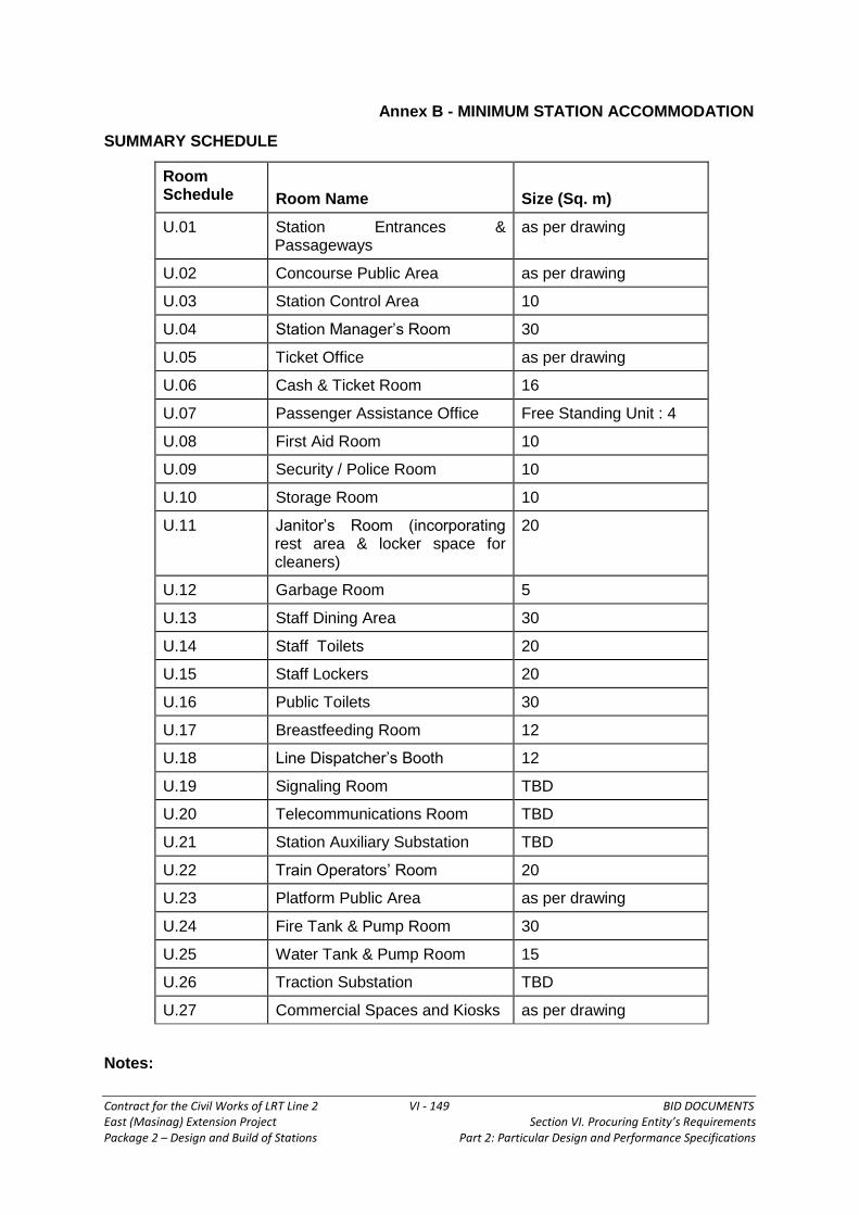
Contract for the Civil Works of LRT Line 2 VI - 149 BID DOCUMENTS East (Masinag) Extension Project Section VI. Procuring Entity’s Requirements Package 2 – Design and Build of Stations Part 2: Particular Design and Performance Specifications
Annex B - MINIMUM STATION ACCOMMODATION
SUMMARY SCHEDULE
Room Schedule
Room Name
Size (Sq. m)
U.01 Station Entrances & Passageways
as per drawing
U.02 Concourse Public Area as per drawing
U.03 Station Control Area 10
U.04 Station Manager’s Room 30
U.05 Ticket Office as per drawing
U.06 Cash & Ticket Room 16
U.07 Passenger Assistance Office Free Standing Unit : 4
U.08 First Aid Room 10
U.09 Security / Police Room 10
U.10 Storage Room 10
U.11 Janitor’s Room (incorporating rest area & locker space for cleaners)
20
U.12 Garbage Room 5
U.13 Staff Dining Area 30
U.14 Staff Toilets 20
U.15 Staff Lockers 20
U.16 Public Toilets 30
U.17 Breastfeeding Room 12
U.18 Line Dispatcher’s Booth 12
U.19 Signaling Room TBD
U.20 Telecommunications Room TBD
U.21 Station Auxiliary Substation TBD
U.22 Train Operators’ Room 20
U.23 Platform Public Area as per drawing
U.24 Fire Tank & Pump Room 30
U.25 Water Tank & Pump Room 15
U.26 Traction Substation TBD
U.27 Commercial Spaces and Kiosks as per drawing
Notes:

Contract for the Civil Works of LRT Line 2 VI - 150 BID DOCUMENTS East (Masinag) Extension Project Section VI. Procuring Entity’s Requirements Package 2 – Design and Build of Stations Part 2: Particular Design and Performance Specifications
The above schedule is included in order to:-
Indicate the minimum requirements which shall be included but which is
not limited to the spaces indicated.
Illustrate the Generic content which shall be reassessed on an individual
station specific basis so as to determine the final requirements.

Contract for the Civil Works of LRT Line 2 VI - 151 BID DOCUMENTS East (Masinag) Extension Project Section VI. Procuring Entity’s Requirements Package 2 – Design and Build of Stations Part 2: Particular Design and Performance Specifications
Annex C - STATION ACCOMMODATION
SCHEDULE OF SPECIFIC STATION ACCOMMODATION
Detailed information relating to specific station accommodation included is as follows:
U.03. Station Control Area
U.04. Station Manager’s Room
U.05. Ticket Office
U.06. Cash and Ticket Room
U.07. Ticket Hall Supervisor & Excess Fare Collection - (Passenger Assistance
Office)
U.08. First Aid Room
U.09. Security/Police Room
U.10. Storage Room
U.11. Janitor’s Room
U.12. Garbage Room
U.13 Staff Dining Area
U.14. Staff Toilets
U.15. Staff Lockers
U.16. Public Toilets
U.17. Breastfeeding Room
U.18. Line Dispatcher’s Booth
U.19. Signaling Room
U.20. Telecommunications Room
U.21. Station Auxiliary Substation
U.22. Train Operators’ Room
U.24. Fire Tank and Pump Room
U.25. Water Tank and Pump Room
U.26. Traction Substation
U.27. Commercial Spaces and Kiosks
SPECIFIC ROOM REQUIREMENTS
U.03 Station Control Room
Function The center for supervision of all passenger related activities on the
station. Holds communication and emergency controls for station plant
such as elevators, escalators, fire detection and suppression. Acts as an
emergency control center for the station and liaison with outside parties,

Contract for the Civil Works of LRT Line 2 VI - 152 BID DOCUMENTS East (Masinag) Extension Project Section VI. Procuring Entity’s Requirements Package 2 – Design and Build of Stations Part 2: Particular Design and Performance Specifications
including Fire and Emergency Services
Location At Concourse Level incorporated in the ticket booth. The room must be
located so as to have a good overview of concourse activities and be
accessible from the non-paid area.
Size Approx. 10 sq. m.
Design The floor of the office shall be elevated 200mm above the concourse floor
level using a suspended floor system with cabling below. Internal control
desk and panels to be carefully laid out so as to be functional, uncluttered
and efficient. The room requires a large vision panel, constructed of fire
rated glass or provided with a fire shutter for a non– fire rated vision
window. Sufficient space will be required for the provision of cabinets,
notice boards and other mounted equipment.
Signaling Provision for a Local control panel.
Communications Desk or counter with automatic and direct line telephones, electronic mail
and CCTV monitors, radio, public address and passenger display facilities
and associated panels. Station Master Clock
AFC Concourse ticket gate control and indications (equipment monitoring and
control) unit. Emergency release button. Station accounting system.
Escalators Monitoring of Emergency Stop Buttons
ECS Air conditioning: Provisions to be supplied via a split–type package unit
with treated fresh air supply which will maintain the room at a slightly
positive pressure.
Electric supply Provision of Mains Distribution Board and lighting panel
Services Lighting: average 300 lux at desk working level.
Power: general purpose sockets:
Fire protection: Station fire alarm panel, automatic smoke detection
systems, plus portable fire extinguisher
Links to fire alarm panels of associated development areas that may
impact on passenger access and egress.
U.04. Station Manager’s Office
Function To provide office accommodation for the Station Manager. It also holds
space for several staff and an area for entertaining guests.
Location Adjacent to the Cash Room.
Size Approx. 30 sq. m.
ECS Air conditioning: Provisions to be supplied via a split–type package unit
with treated fresh air supply which will maintain the room at a slightly
positive pressure.
Services Lighting: average 300 lux at desk working level.

Contract for the Civil Works of LRT Line 2 VI - 153 BID DOCUMENTS East (Masinag) Extension Project Section VI. Procuring Entity’s Requirements Package 2 – Design and Build of Stations Part 2: Particular Design and Performance Specifications
Power: general purpose sockets:
Fire protection: automatic smoke detection systems plus portable fire
extinguishers.
U.05. Ticket Office
Function To facilitate the sale of tickets
Location Located inside the ticket booth at the unpaid concourse area. Care must
be taken to ensure that queuing areas associated with this facility do not
obstruct normal passenger flows between entrances and ticket gates.
Size Depends on number of ticket office windows required
Design The floor level shall be 200 mm above concourse level. Speech transfer
facilities will be required in the windows and induction loops.
ECS Air conditioning: Provisions to be supplied via a split–type package unit
with treated fresh air supply, which will maintain the room at a slightly
positive pressure.
Services Lighting: average 300 lux at desk working level.
Power : general purpose sockets:
Fire protection: automatic smoke detection system, plus portable fire
extinguishers.
U.06. Cash and Ticket Room
Function To provide secure storage for cash, tickets, cash vaults, cash trolley, and
accountancy and security documents. To provide a secure area for the
hand over of value items between station staff and courier or delivery
staff. To house local control equipment for the automatic fare collection
equipment, equipment for counting cash. Will be used for auditing
purposes and for storage of cash trolleys, trolley vault transporters, vaults
and document drawers. A separate cash vault with access via a vault
door is required to store cash vaults for a period of time when collection
services are disrupted.
Location Preferably at concourse level within the paid area for added security but
could be elsewhere.
Size 16 sq. m. depending on the volume of traffic
Communications Automatic telephone
AFC Ticket encoder / sorter, ticket magazine rack, cash counting & bagging
equipment.
ECS Air conditioning: Provisions to be supplied via a split–type package unit
with treated fresh air supply which will maintain the room at a slightly
positive pressure
Services Lighting: average 300 lux at desk height

Contract for the Civil Works of LRT Line 2 VI - 154 BID DOCUMENTS East (Masinag) Extension Project Section VI. Procuring Entity’s Requirements Package 2 – Design and Build of Stations Part 2: Particular Design and Performance Specifications
Power: general purpose socket outlets
Fire protection: automatic smoke/heat detection systems plus portable
Fire extinguishers.
Furnishings Secure cabinets, safe, shelving, desk & chair
U.07. Ticket Hall Supervisor & Excess Fare Collection [Passenger Assistance Office]
Function This office shall be located in the most suitable position for supervising
the movement of passengers to the maximum extent feasible within the
concourse and between the gates and platform level. AFC gates and
Ticket Machines shall be supervised from this office and it will also be
used for the collection of Excess Fares.
Location The office should be located adjacent to the barrier gates.
Size 4–6 sq. m.
Design The floor of the office should be elevated 200 mm above the concourse
floor level. It should be constructed of non-combustible materials, with
vision panels of non-reflective glass. Service counter with speak through
unit will be required for the collection of excess fares.
ECS Air conditioning: Provisions to be supplied via a split-type package unit
with treated fresh air supply, which will maintain the room at a slightly
positive pressure (Dependent on the specific requirements).
Services Lighting: average 300 lux at desk working level.
Power: general purpose sockets:
Fire protection: automatic smoke detection system plus portable fire
extinguishers.
U.08. First Aid Room
Function To provide a private area for rendering first aid to passengers or staff, to
store first aid equipment and supplies.
Location Not significant
Size 10 sq. m.
Communications Automatic Telephone
ECS Air conditioning: Provisions to be supplied via a split-type package unit
with treated fresh air supply, which will maintain the room at a slightly
positive pressure.
Services Lighting: average 300 lux at table height
Power: general purpose socket outlets
Fire protection: automatic smoke detection system plus portable fire
extinguishers.
Plumbing: cold water, hot water, floor gully

Contract for the Civil Works of LRT Line 2 VI - 155 BID DOCUMENTS East (Masinag) Extension Project Section VI. Procuring Entity’s Requirements Package 2 – Design and Build of Stations Part 2: Particular Design and Performance Specifications
Furnishings Storage cabinets, desk and chair, first aid table/bed, stretcher and
stretcher case, wash basin, medical inspection lamp.
U.09. Security/Police Room
Function To provide office accommodation for the use of the security personnel
and/or police.
Location Preferably near to staff areas and toilets
Size 10 sq. m
Communications Automatic Telephone
ECS Air conditioning: Provisions to be supplied via a split–type package unit
with treated fresh air supply, which will maintain the room at a slightly
positive pressure.
Services Lighting: average 200 lux at table height
Power: general purpose socket outlets
Fire protection: automatic smoke detection system and portable fire
extinguishers.
Furnishings Storage cabinets, desk and chairs
U.10. Storage Room
Function To store materials, some of which may be flammable or toxic, mops,
brooms, dusters and other cleaning tools. Space for powered cleaning
machines should be provided. Mops, dusters etc. will need to be hung to
dry.
Location Not significant
Size Approx. 10 sq. m.
Ventilation Mechanical extract system
Services Lighting: average 150 lux at floor level
Plumbing: cold water, floor gully
Fire Protection: automatic smoke/heat detection and sprinkler systems
plus portable fire extinguishers
Furnishings Shelving, metal storage bins for flammables, cleaners sink and hanging
racks.
U.11. Janitor’s Room
Function For cleaner’s general storage and cleaning equipment storage.
Location Concourse unpaid area
Size 20 sq. m.
Services Lighting: average 150 lux at floor level

Contract for the Civil Works of LRT Line 2 VI - 156 BID DOCUMENTS East (Masinag) Extension Project Section VI. Procuring Entity’s Requirements Package 2 – Design and Build of Stations Part 2: Particular Design and Performance Specifications
Plumbing: cold water, floor gully
Fire Protection: automatic smoke/heat detection and sprinkler systems
plus portable fire extinguishers
Ventilation: grills at top and bottom for free air circulation.
Furnishings Cleaner’s sink, storage cabinets/shelves
U.12. Garbage Storage
Function To hold refuse collected in the station until it can be disposed of by public
or contract disposal agents
Location Adjacent to a street access or at street level preferably under the stairs.
Size 5 sq. m.
Services Lighting: average 150 lux at floor level
Plumbing: cold water, floor gully
Fire Protection: automatic smoke/heat detection system plus portable
fire extinguishers.
Ventilation: grills at top and bottom for free air circulation.
Furnishings Fireproof metal storage bins
U.13. Staff Dining
Function To provide a location where staff can relax on work breaks and eat food
they obtain from outside.
Location Near staff toilet and locker facilities within the staff/administrative zone.
Size Dependent on number of station staff
Communications Automatic Telephone
ECS Air conditioning: Provisions to be supplied via a split-type package unit
with treated fresh air supply, which will maintain the room at a slightly
positive pressure.
Services Lighting: 150 -250 lux
Power: general purpose socket outlets
Fire Protection: automatic smoke/heat detection plus portable fire
extinguishers
Plumbing: Well water, sink, floor gully
Appliances Refrigerator, electric cooker and microwave oven for meals
Furnishings Dining table, chairs, sink unit and pantry cabinets
Equipment Chilled drinking water facilities are to be provided, with related servicing
included portable fire extinguisher.

Contract for the Civil Works of LRT Line 2 VI - 157 BID DOCUMENTS East (Masinag) Extension Project Section VI. Procuring Entity’s Requirements Package 2 – Design and Build of Stations Part 2: Particular Design and Performance Specifications
U.14. Staff Toilets
Function To provide toilet and washing facilities for station staff, maintenance staff
and in emergency, train drivers. Separate toilet facilities for male and
female employees. The operator may permit staff from commercial units’
access to these facilities.
Location Preferably at concourse level at one end of the concourse.
Size To accommodate the required facilities.
Ventilation Mechanical extract system which will maintain the room at a negative
pressure
Services Lighting: average 150 - 200 lux at floor level
Plumbing: Hot and cold water, wash hand basins, showers, floor
gully
Furnishings Dependent on staffing numbers but a minimum of:
Male: 1 urinal, 2 WC cubicle, 1 washbasins, mirror, electric
hand drier
Female: 2 WC, 2 wash basin, mirror, 1 electric hand drier.
U.15. Staff Lockers
Function To provide a location where staff can store personal items and issued
items of documentation or equipment. Separate areas for use by male
and female staff for changing and storage of personal belongings.
Location Near staff toilet facilities within the staff/administrative zone.
Size Dependent on number of station staff
Communications Automatic Telephone
Ventilation Mechanical extract system which will maintain the room at a negative
pressure
Services Lighting: 150 -250 lux
Power: general purpose socket outlets
Fire Protection: automatic smoke/heat detection plus portable fire
extinguishers
Furnishings Full height lockers for assigned staff, stacked half-height lockers for
roving staff. Benches, Coat hooks and Mirrors, clothes hanging/drying
space.
U.16. Public Toilets
Function To provide toilet facilities for use by the public, including the provision for
disabled facilities. To include diaper changing table in the female toilet.
Location Dependent upon station layout. A location within the unpaid area is
preferred.

Contract for the Civil Works of LRT Line 2 VI - 158 BID DOCUMENTS East (Masinag) Extension Project Section VI. Procuring Entity’s Requirements Package 2 – Design and Build of Stations Part 2: Particular Design and Performance Specifications
Size Dependent upon requirement
Ventilation Mechanical extract system which will maintain the room at a negative
pressure
Services Lighting: average 100 - 200 lux at floor level
Plumbing: Well water, wash hand basins, floor gully
U.17. Breastfeeding Room
Function To provide facilities for use by lactating mothers, including the provision
for milk extraction facilities.
Location Dependent upon station layout. A location within the unpaid area is
preferred.
Size 12 sq. m.
ECS Air conditioning: Provisions to be supplied via a split-type package unit
with treated fresh air supply, which will maintain the room at a slightly
positive pressure.
Services Lighting: average 200 lux at table level
Plumbing: Well water, wash hand basins, floor gully
Furnishings Upholstered chairs, tables
U.18. Line Dispatcher’s Booth
Function: Monitor and supervise platform management and dispatch of train.
Size: 12 sq. m.
Design: It should be constructed of non-combustible materials, with vision panels
of non-reflective glass.
Communications PABX, Radio coverage, CCTV, Telephone with direct lines to Station
Control Room, P/A, Signaling Indication
ECS Air conditioning: Provisions to be supplied via a split type package unit
with treated fresh air supply, which will maintain the room at a slightly
positive pressure (Dependent upon site specific circumstances).
Services Lighting: 200 lux
Power: general purpose socket outlets
Fire protection: automatic smoke/heat detection system and portable
fire extinguishers.
Furnishings: Working desk, filing cabinets, drawers, stretcher
U.19. Signaling Room
Function To house signaling equipment
Location End of platforms preferred well separated from rooms containing

Contract for the Civil Works of LRT Line 2 VI - 159 BID DOCUMENTS East (Masinag) Extension Project Section VI. Procuring Entity’s Requirements Package 2 – Design and Build of Stations Part 2: Particular Design and Performance Specifications
transformers.
Size 40 sq. m.
[As required depending on equipment requirements at specific locations].
Design No window, glass block or light penetrable panel shall be allowed. Air
outlets must not be installed above signaling equipment to avoid
condensate from dripping onto the signaling equipment thereby affecting
safety and system performance. The room shall be sealed against the
ingress of dust. Service piping such as rainwater down pipes and SWC
cables etc. should not be routed through the room and must not be
located near, above or under water pump / fuel / pantry rooms.
All services shall be located above a certain height to be coordinated with
the signaling contractor. A minimum clear height of 3.2 meters is required
to a ceiling level; although a false ceiling will not be required.
Door–ways must provide a clear opening of at least 1.200 meters wide
and 2.100 meters high.
Communications Automatic and maintenance telephones
ECS Air–conditioning: Provisions to be supplied to maintain the room at the
required temperature of 24+ 2o C with a positive pressure via the use of 2
No. split–type package units – (one unit to act as a stand by facility to the
other)
Services Lighting : average 200 lux at floor level
Power: general purpose socket outlets
Fire Protection: automatic smoke detection and portable fire
extinguishers.
U.20. Telecommunications Room
Function To house communications equipment
Location Adjacent to or as near as possible to the station control room but well
separated from station substation. Access to equipment by unobstructed
path from station service corridor.
Size 20 sq. m.
Design No window or glass block shall be allowed. Air outlets must not be
installed above telecommunication equipment to avoid condensate from
dripping onto the telecommunication equipment affecting system
performance.
Floor, wall and ceiling materials and finishes coated or sealed to maintain
a dust free environment. Service piping such as rainwater down pipes
and SWC cables etc., should not be routed through the room. The room
must not be located near, above or under water pump/fuel/pantry rooms.
All services shall be located above a certain height to be coordinated with
the telecommunication contractor. A minimum clear height of 3.2 meters
is required to ceiling level. Doorways must provide a clear opening of at

Contract for the Civil Works of LRT Line 2 VI - 160 BID DOCUMENTS East (Masinag) Extension Project Section VI. Procuring Entity’s Requirements Package 2 – Design and Build of Stations Part 2: Particular Design and Performance Specifications
least 1.2 meters wide and 2.1 meters high. False ceiling is not required.
Communications Automatic and maintenance telephones
ECS Air-conditioning: Provisions to be supplied to maintain the room at the
required temperature of 24+ 2o C with a positive pressure via the use of 2
No. split–type package units – (one unit to act as a stand by facility to the
other)
Services Lighting - Normal: 300 lux at floor level
- Emergency: 100 lux
Power - General purpose socket outlets with MCB distribution
panels.
Fire Protection automatic smoke detection and portable fire
extinguishers.
U.21. Station Auxiliary Substation
Function To house equipment for stepping down the voltage.
Location Convenient for access to incoming and outgoing cables.
Size As required depending on equipment requirements at specific locations.
Communications Automatic power and maintenance telephones
ECS Ventilation: Combined mechanical ventilation and smoke
extract system
Services Lighting - average 200 lux at floor level
Power - general purpose socket outlets
Fire Protection: automatic smoke detection and portable fire
extinguishers
U.22. Train Operator’s Room
Function To provide accommodation for train crew to change clothing, store issued
documents and equipment and personal effects.
Location At designated Stations. At platform level.
Size To be determined in relation to distribution of train crews between
locations.
ECS Air conditioning: Provisions to be supplied via a split-type package unit
with treated fresh air supply, which will maintain the room at a slightly
positive pressure.
Communications Automatic Telephone
Services Lighting: average 200 lux at desk height
Power: general purpose socket outlets
Plumbing: Hot and Cold water, sink, floor gully

Contract for the Civil Works of LRT Line 2 VI - 161 BID DOCUMENTS East (Masinag) Extension Project Section VI. Procuring Entity’s Requirements Package 2 – Design and Build of Stations Part 2: Particular Design and Performance Specifications
Fire protection: automatic smoke/heat detection plus portable fire
extinguishers.
Furnishings Wardrobe lockers for the maximum number of staff, hanging
space for clothing, chairs
U.24-25. Fire Water Tank and Pump Room & Domestic Water Tank and Pump Room
Function Room or space to house pumps for firefighting purposes and to provide to
the station’s water supply needs. Provide access to the water tanks from
the pump rooms.
Location Adjacent to the water tank at ground level which allows the pumps to
operate with a positive suction pressure
Size As required depending on equipment requirements at specific locations.
ECS Ventilation: mechanical exhaust system
Services Lighting - average 200 lux at floor level
Power - general purpose socket outlets
Fire Protection: automatic smoke detection
Drainage - sump and mercury float level switch
U.26. Traction Substation
Function A Traction Substation comprises a number of spaces housing the
following equipment:
Rectifier Transformers
Rectifiers
DC Switchgear
Inverter Transformer [at certain traction sub-stations]
Inverter [at selected traction sub-stations]
LV AC Distribution Panel
110v DC Distribution Panel
Track Earthing Panel
DC Smoothing Reactor
RTU for SCADA
Control Equipment and Relay Panels
Battery Room
Switchgear
Store Room - for vital Spares, Instruments, etc.
Allocated Space for maintenance facilities- [i.e.: vertical hoists, Travelling
hoists, etc...] .

Contract for the Civil Works of LRT Line 2 VI - 162 BID DOCUMENTS East (Masinag) Extension Project Section VI. Procuring Entity’s Requirements Package 2 – Design and Build of Stations Part 2: Particular Design and Performance Specifications
Tracks for the movement of Rectifier Transformers
Location As indicated on drawings
Size Dependent on the Supply Authority, particular equipment sizes,
maintenance and access requirements
Communications All spaces except rectifier Transformers - Automatic, power and
maintenance telephones
ECS Rectifier Transformers - Mechanical Ventilation depending on degree of
enclosure of the room enclosure of the room
Rectifiers - Ventilation: combined mechanical ventilation
and smoke extract system
DC Switchgear - Ventilation: combined mechanical ventilation
and smoke extract system
Control Equipment
& Relay Panels - Ventilation: mechanical extract system
Battery Room - Ventilation: individual mechanical extract
system
Switchgear - Ventilation: combined mechanical ventilation
and smoke extract system
Services Lighting
Rectifier Transformer Area- average 200 lux at floor level
Rectifiers - average 200 lux at floor level
DC Switchgear - average 200 lux at floor level
Control Equipment
& Relay Panels Average 300 lux at panel area
Battery Room average 100 lux at floor level
Switchgear - average 200 lux at vertical surface 600
mm above floor level
Power
Rectifier Transformers - general purpose socket outlets
Rectifiers - general purpose socket outlets
DC Switchgear - general purpose socket outlets
Control Equipment and
Relay Panels general purpose socket outlets
Battery Room general purpose socket outlets
Switchgear general purpose socket outlets
Fire Protection
Rectifier Transformers &

Contract for the Civil Works of LRT Line 2 VI - 163 BID DOCUMENTS East (Masinag) Extension Project Section VI. Procuring Entity’s Requirements Package 2 – Design and Build of Stations Part 2: Particular Design and Performance Specifications
Inverter Transformers - automatic smoke/heat detection
system and portable fire extinguishers
Rectifiers & Inverters - automatic smoke/heat detection system
and portable fire extinguishers
DC Switchgear - automatic smoke/heat detection system
and portable fire extinguishers and portable fire extinguishers
Control Equipment
& Relay Panel - automatic smoke/heat detection system
and portable fire extinguishers and portable fire extinguishers
Battery Room - automatic smoke/heat detection system
Switchgear - automatic smoke/heat detection system
and portable fire extinguishers. and portable fire extinguishers
N.B. A Cable Way / Gallery route for Duct banks shall be provided between
Traction Sub-Stations and Station facilities.
U.27. Commercial Outlets and Kiosks
Function Commercial outlets and kiosks shall only be provided in designated areas
Location They shall be located within the unpaid area of the station complex in such
a manner that there shall be no interference with passenger flow to or
within the concourse areas. Their location shall be subject to approval
from relevant authorities and they may be limited in size and the amount
and type of goods for sale in that these may be a fire or safety risk
affecting either the safety of passengers or operation of the railway.
Design All finishes, floors, walls, ceilings, shop fronts and services shall be
carried out by others, except that approval will be required to coordinate
the visual appearance with railway requirements.
Size As approved
Services To be independent from the station system. Each concession shall be
supplied with an endorsed fire service installation, power supply and
telephone point.