pedestrian design guidelines.pdf
TRANSCRIPT
8/11/2019 Pedestrian Design Guidelines.pdf
http://slidepdf.com/reader/full/pedestrian-design-guidelinespdf 1/50
Appendix C: Pedestrian Design Guidelines

8/11/2019 Pedestrian Design Guidelines.pdf
http://slidepdf.com/reader/full/pedestrian-design-guidelinespdf 2/50
This page intentionally left blank

8/11/2019 Pedestrian Design Guidelines.pdf
http://slidepdf.com/reader/full/pedestrian-design-guidelinespdf 3/50
Chula Vista Pedestrian Master Plan 1 Draft Pedestrian Design Guidelines
1.0 R ATIONALE FOR THE DESIGN GUIDELINES
Designing streets so that they encourage people to walk by providing an experience that is safe,comfortable and attractive is an important element to creating vibrant and active urban areas. The
purpose of the Pedestrian Design Guidelines is to integrate existing resources and current best practicesinto one coherent set of guidelines aimed at improving the pedestrian experience in Chula Vista. Theseguidelines are meant for inclusion in the City’s Street Design Standards. They should be used byengineers, planners, policy makers, and the public to guide decisions related to new construction as wellas retrofitting existing infrastructure.
The following guidelines recommended for use by the City of Chula Vista primarily address issues ofpedestrian safety, and secondarily, issues of urban design, design character, and the many other amenitiesthat make streets and sidewalks attractive places to travel and spend time as a pedestrian. It is clear thatsafety concerns can significantly influence a person’s decision to walk or use other modes oftransportation. Where people aren’t walking, it is often because they are prevented or discouraged fromdoing so. Either the infrastructure is insufficient, has serious gaps, or there are safety hazards. These
design guidelines present many design and infrastructure improvements that will help the City of Chula Vista to better accommodate pedestrians’ needs and build a stronger walking community.
The guidelines included in this chapter are supplemental to the City of Chula Vista’s currently adopteddevelopment policies, as well as State and Federal standards. The purpose of this chapter is not toreplace City standards, but to provide general design guidelines for pedestrian facilities that goabove the minimum standards. Final design of any pedestrian facility should be conducted by alicensed engineer using sound engineering judgment, applicable standards and guidelines.
2.0 STATE AND FEDERAL GUIDELINES
The design of many streetscape elements is regulated by state and federal law. Traffic control devices
must follow the procedures set forth in the Manual of Uniform Traffic Control Devices (MUTCD), while elements such as sidewalks and curb cuts must comply with guidelines implementing the Americans with Disabilities Act (ADA).
Manu a l o f Un i f o r m T r a f f i c Co n t r o l De v i c es
The City of Chula Vista follows the procedures and policies set out in the CA MUTCD (state) andMUTCD (federal). Traffic control devices include traffic signals, traffic signs, and street markings. Themanual covers the placement, construction, and maintenance of devices. The CA MUTCD emphasizesuniformity of traffic control devices to protect the clarity of their message. A uniform device conformsto regulations for dimensions, color, wording, and graphics and minimizes confusion or
misunderstanding on the part of the roadway user. Uniformity also means treating similar situations inthe same way.
Re v i s e d Dr a f t Gu i d e l i n e s f o r Ac ce ssi b l e Pu b l i c Ri g h t s- o f -Wa y
The Americans with Disabilities Act (ADA) is civil rights legislation that prohibits public entities fromdiscrimination on the basis of disability. Under the ADA, state and local government facilities, publicplaces, and commercial facilities must meet design requirements to ensure these facilities are accessible to

8/11/2019 Pedestrian Design Guidelines.pdf
http://slidepdf.com/reader/full/pedestrian-design-guidelinespdf 4/50
Chula Vista Pedestrian Master Plan 2 Draft Pedestrian Design Guidelines
people with disabilities. The U.S. Access Board maintains three sets of guidelines that establishminimum accessibility standards: the Americans with Disability Act Accessibility Guidelines (ADAAG), Architectural Barriers Act (ABA) guidelines, and the Revised Draft Guidelines for Accessible PublicRights-of-Way. The City of Chula Vista utilizes the U.S. Access Board’s Revised Draft Guidelines for Accessible Public Rights-of-Way for implementing accessibility standards within the public right-of-way. These draft guidelines are currently under public review. Although these guidelines have not been
formally adopted, they represent the most current state-of-the-art with respect to accessibility in thepublic right-of-way. The guidelines were also written to apply to new construction. The extent to whichthey should be applied to major alterations and retrofits is still under review by the Access Board andDepartment of Justice (DOJ). These guidelines specifically pertain to the public right-of-way, whereasthe ADAAG and ABA apply primarily to buildings and facilities standards. According to the AccessBoard, “While [the ADAAG and ABA] address certain features common to public sidewalks, such ascurb ramps, accessible routes, ground and floor surfaces, and bus stop shelters, further guidance isnecessary to address conditions unique to public rights-of-way”. In addition to these federal guidelines,cities in California can refer to California Title 24 State Accessibility Standards, State ArchitecturalRegulations for Accommodation of the Physically Handicapped in Public Facilities for accessibilityguidelines.
3.0 PRINCIPLES OF PEDESTRIAN DESIGN
The following design principles represent a set of ideals which should be incorporated, to some degree,into every pedestrian improvement. They are ordered roughly in terms of relative importance.
The pedestrian environment should be safe.Sidewalks, walkways, and crossings should be designed and built to be free of hazards and tominimize conflicts with external factors such as noise, vehicular traffic, and protrudingarchitectural elements.
The pedestrian network should be accessible to all.Sidewalks, walkways, and crosswalks should ensure the mobility of all users by accommodatingthe needs of people regardless of age or ability.
The pedestrian network should connect to places people want to go. The pedestrian network should provide continuous direct routes and convenient connectionsbetween destinations, including homes, schools, shopping areas, public services, recreationalopportunities and transit.
The pedestrian environment should be easy to use. Sidewalks, walkways, and crossings should be designed so people can easily find a direct route to
a destination and will experience minimal delay.
The pedestrian environment should provide good places.Good design should enhance the look and feel of the pedestrian environment. Thepedestrian environment includes open spaces such as plazas, courtyards, and squares, as wellas the building facades that give shape to the space of the street. Amenities such as seating,street furniture, banners, art, plantings, shading, and special paving, along with historicalelements and cultural references, should promote a sense of place.
The pedestrian environment should be used for many things.

8/11/2019 Pedestrian Design Guidelines.pdf
http://slidepdf.com/reader/full/pedestrian-design-guidelinespdf 5/50
Chula Vista Pedestrian Master Plan 3 Draft Pedestrian Design Guidelines
The pedestrian environment should be a place where public activities are encouraged.Commercial activities such as dining, vending, and advertising may be permitted when theydo not interfere with safety and accessibility.
Pedestrian improvements should preserve or enhance the historical qualities of a placeand the City.
Chula Vista’s history must be preserved in the public space. Where applicable, pedestrianimprovements should restore and accentuate historical elements of the public right-of-way.Good design will create a sense of time that underscores the history of Chula Vista.
Pedestrian improvements should be economical. Pedestrian improvements should be designed to achieve the maximum benefit for their cost,
including initial cost and maintenance cost as well as reduced reliance on more expensivemodes of transportation. Where possible, improvements in the right-of-way shouldstimulate, reinforce, and connect with adjacent private improvements.
The remaining sections of this memorandum delineate pedestrian facility designs. A brief description,graphics, list of potential applications, and summary of standards is provided for each design typepresented. Specific designs are organized into the following general topics:
4.0 Sidewalk Corridor Guidelines
5.0 Sidewalk Grade and Cross Slope
6.0 Curb Ramps
7.0 Railroad Crossings
8.0 Pedestrian Amenities
9.0 Crosswalks
10.0 Pedestrian Signage
11.0 Design Treatments for Crosswalks
12.0 Traffic Signal Enhancements13.0 Pavement Markings
14.0 Transit Stops
15.0 Pedestrian Trails

8/11/2019 Pedestrian Design Guidelines.pdf
http://slidepdf.com/reader/full/pedestrian-design-guidelinespdf 6/50
Chula Vista Pedestrian Master Plan 4 Draft Pedestrian Design Guidelines
4.0 SIDEWALK CORRIDOR GUIDELINES
The guidelines presented in this sidewalk corridor section apply to sidewalks in new development areas,redevelopment areas, and in areas where street reconstruction is planned.
Proposed sidewalk corridor guidelines depend on available street width, motor vehicle volumes,surrounding land uses, and pedestrian activity levels. Standardizing sidewalk guidelines for differentareas of the city ensures a minimum level of quality for all sidewalks.
4 . 1 Si d ewa l k Co r r i d o r s – Ur b an Se t t i n g
Description
Sidewalks are the most important component of Chula Vista’s pedestrian circulation network.Sidewalks provide pedestrian access to virtually every activity and provide critical connections betweenother modes of travel, including the automobile, public transit, and bicycles. The Sidewalk Corridor islocated within the public right-of-way between the curb or roadway edge and the property line. The
Sidewalk Corridor contains four distinct zones: the Curb Zone, the Furnishing Zone, the ThroughPedestrian Zone, and the Frontage Zone as displayed in the following figure.
Graphic
Source: Alta Planning + Design, 2010

8/11/2019 Pedestrian Design Guidelines.pdf
http://slidepdf.com/reader/full/pedestrian-design-guidelinespdf 7/50
Chula Vista Pedestrian Master Plan 5 Draft Pedestrian Design Guidelines
Potential Applications
Sidewalks in commercial zones with right-of way widths of approximately 80 feet, and sidewalk widths of approximately 15 feet.
Elements
Curb Zone
Curbs prevent water in the street gutters from entering the pedestrian space and discourage vehiclesfrom driving over the pedestrian area. In addition, the curb helps to define the pedestrian environment within the streetscape. At the corner, the curb is an important tactile element for pedestrians who arefinding their way with the use of a cane. Straight curbs rather than rolled curbs are stronglyrecommended because it eliminates the potential for cars to park on the sidewalk or partiallyobstructing the sidewalk.
Furnishing Zone
All streets require a utility zone to accommodate above ground public infrastructure, signage, and streettrees. Locating this infrastructure in the Furnishing Zone prevents it from encroaching on the ThroughPedestrian Zone, where it is likely to cause accessibility issues. The Furnishing Zone also creates animportant buffer between pedestrians and vehicle travel lanes by providing horizontal separation.Elements like utility poles, sign posts, and street trees improve pedestrian safety and comfort by furtherseparating the sidewalk from moving vehicles. Four feet is the minimum width for Furnishing Zonesthat include trees; six to eight feet is the preferred width for Furnishing Zones with trees. Additionalguidelines for the Furnishing Zone are discussed in Section 4.2.
Through Pedestrian Zone
Many residential areas are low to medium density and therefore have low pedestrian volumes,compared to more urban areas. A five foot Through Pedestrian Zone is recommended for theseconditions. Some commercial areas, school zones, and other public areas generate greater pedestrian volumes where a wider than five foot through zone should be considered. The Through PedestrianZone provides the minimum clear width required for safe pedestrian movement. The minimumcontinuous and unobstructed clear width of a pedestrian route, including along sidewalks, is four feet
Frontage Zone
The Frontage Zone is the space between the Through Pedestrian Zone and the adjacent property line.Pedestrians tend to avoid walking close to barriers at the property line, such as buildings, storefronts, walls or fences, in the same way that they tend to avoid walking close to the roadway. In most cases theFrontage Zone should be at least 12 inches. However, if the sidewalk is adjacent to a wide open or
landscaped space, such as in residential areas where fences are not typically found or not allowed, theFrontage Zone can be eliminated. Guidelines for Frontage Zones are presented in Section 4.4. AFrontage Zone may not be required in some residential areas of Chula Vista with deep front yardsetbacks.
The Furnishing Zone, Through Pedestrian Zone, and Frontage Zone are discussed in further detail inthe subsequent sections.

8/11/2019 Pedestrian Design Guidelines.pdf
http://slidepdf.com/reader/full/pedestrian-design-guidelinespdf 8/50

8/11/2019 Pedestrian Design Guidelines.pdf
http://slidepdf.com/reader/full/pedestrian-design-guidelinespdf 9/50
Chula Vista Pedestrian Master Plan 7 Draft Pedestrian Design Guidelines
Street Furniture
Street furniture includes benches, mailboxes, trash and recycling receptacles, bike racks, newspaperboxes, drinking fountains, information boards, kiosks, parking meters, artwork, public phones, signs,bus shelters, and other items used by pedestrians. These features humanize the scale of a street and
encourage pedestrian activity. Street furniture should be placed in the furnishings zone to maintainthrough passage zones for pedestrians and to provide a buffer between the sidewalk and the street.
Utility Poles and Structures
The City’s underground and overhead network of utility services greatly impacts sidewalks. Utilitypoles, traffic signals, and fire hydrants should be installed outside the Through Passage Zone. Whenever possible, electrical boxes should be located on utility, traffic signal or light poles (spacepermitting) so they do not create unexpected hazards to pedestrians. Utility vaults and access boxesshould be located outside the Through Passage Zone and be constructed from non-slip materials thatare flush with the sidewalk, in conformance with ADA requirements.
Examples of Street Furniture

8/11/2019 Pedestrian Design Guidelines.pdf
http://slidepdf.com/reader/full/pedestrian-design-guidelinespdf 10/50
Chula Vista Pedestrian Master Plan 8 Draft Pedestrian Design Guidelines
4 . 3 T h r o u g h Pe d e st r i a n Z o n e
Description
The Through Pedestrian Zone is the area intended for pedestrian travel. This zone should be entirely
free of permanent and temporary objects. For sidewalk infill projects in areas with some existingsidewalks, the new sidewalk should match the existing width or meet the recommended width whichever is larger. Driveway aprons should not intrude into the Through Pedestrian Zone.
The US Access Board Revised Draft Guidelines for Accessible Public Rights-of-Way specifies that theminimum clearance required for through passage is 48 inches, but may be reduced to 44 inches for vertical obstructions between 27 and 80 inches above the surface of the pedestrian access route.
Graphics
Source: Alta Planning + Design, 2010
The Through Pedestrian Zone is the area of the Sidewalk Corridorintended for pedestrian travel
Potential Applications
All sidewalks

8/11/2019 Pedestrian Design Guidelines.pdf
http://slidepdf.com/reader/full/pedestrian-design-guidelinespdf 11/50
Chula Vista Pedestrian Master Plan 9 Draft Pedestrian Design Guidelines
Summary of Standards
The City of Chula Vista currently requires, at minimum, five foot wide sidewalks paved with PortlandCement Concrete (CVMC 18.32.090). These dimensions conform to the US Access Board RevisedDraft Guidelines for Accessible Public Rights-of-Way that calls for a minimum of four foot wide
continuous, unobstructed pedestrian access routes. Walkways narrower than five feet in clear width must provide five foot wide passing spaces for adistance of five feet at intervals of 200 feet maximum (U.S. Access Board, Revised Draft Guidelines for Accessible Public Rights-of-Way, 2005).

8/11/2019 Pedestrian Design Guidelines.pdf
http://slidepdf.com/reader/full/pedestrian-design-guidelinespdf 12/50
Chula Vista Pedestrian Master Plan 10 Draft Pedestrian Design Guidelines
4 . 4 F r o n t a g e Z o n e
Description
The Frontage Zone is the area between the Through Pedestrian Zone and the property line. This zoneallows pedestrians a comfortable “shy away” distance from the building fronts, in areas where buildings
are at the lot line, or from elements such as fences and hedges on private property. Where no Furnishing Zone exists, elements that would normally be sited in that zone, such as transitshelters and benches, telephone kiosks, signal and street lighting poles and controller boxes, traffic andparking signs, and utility poles, may occupy the Frontage Zone. In some cases, easements or additionalright-of-way may be required to allow for these items. For residential and mixed-use building built tothe right-of-way line, these elements should not be sited in the Frontage Zone, as they could blockaccess to an existing or future building. Private temporary uses such as sidewalk cafes (where allowedby Code) may occupy the Frontage Zone, so long as the Through Pedestrian Zone is maintained.
Graphic
Many businesses along 3 rd Avenue in Chula Vista provide awnings in the Frontage Zone.
Summary of Standards
The ten-foot wide right-of-way behind the face of curb includes areas for utility boxes, either betweenthe sidewalk and property line for contiguous sidewalks or within the parkway or behind the sidewalk
within utility easements for non-contiguous sidewalks.Objects projecting from walls that have leading edges between 27 inches and 80 inches should notprotrude more than 4 inches into pedestrian passage ways (U.S. Access Board, Revised DraftGuidelines for Accessible Public Rights-of-Way, 2005).
Encroachments into the public right-of-way for private purposes by abutting property owners areauthorized in certain circumstances when the encroachment does not obstruct pedestrian traffic. TheCity Engineer is authorized to issue encroachment permits for fences and retaining walls, in accordance with zoning and building codes, not to exceed five feet in height. The Director of Public Works may

8/11/2019 Pedestrian Design Guidelines.pdf
http://slidepdf.com/reader/full/pedestrian-design-guidelinespdf 13/50
Chula Vista Pedestrian Master Plan 11 Draft Pedestrian Design Guidelines
also permit temporary encroachments in the public right-of-way through an application and fee process(MC 12.28.030).
Awnings, canopies, and other accessory shade structures along with planters are permissible anddesirable, provided that they do not restrict pedestrian movement.

8/11/2019 Pedestrian Design Guidelines.pdf
http://slidepdf.com/reader/full/pedestrian-design-guidelinespdf 14/50
Chula Vista Pedestrian Master Plan 12 Draft Pedestrian Design Guidelines
4 . 5 Si d ewa l k Co r r i d o r s – Resi d e n t i a l Se t t i n g
Description
Residential sidewalks are generally narrower than commercial zone sidewalks, and priority should be
given to the Through Pedestrian Zone’s width in residential sidewalk design. Residential sidewalks doinclude the other sidewalk zones, such as for placement of utility boxes in the Furnishing Zone, yetthese zones are less prominent than in commercial or mixed use areas where Furnishing and FrontageZones may feature ample seating and amenities like newsstands.
Graphic
Source: Alta Planning + Design, 2010 Dimensions given for ROW 50 feet or less
Potential Applications
Residential areas with right-of-way widths of approximately 50 feet, and sidewalk widths ofapproximately 10 feet.

8/11/2019 Pedestrian Design Guidelines.pdf
http://slidepdf.com/reader/full/pedestrian-design-guidelinespdf 15/50
Chula Vista Pedestrian Master Plan 13 Draft Pedestrian Design Guidelines
Summary of Standards
Minimum sidewalk width should be five feet.
If established sidewalks are less than five feet wide and no additional right-of-way is available, the
Frontage Zone should be eliminated in the interest of preserving a Through Pedestrian Zone, withthe remaining Furnishing and Curb Zones functioning as a buffer between pedestrians and thestreet.
Minimum clearance required for through passage is 48 inches, but may be reduced to 44 inches for vertical obstructions between 27 and 80 inches above the surface of the pedestrian access route(U.S. Access Board, Revised Draft Guidelines for Accessible Public Rights-of-Way, 2005).

8/11/2019 Pedestrian Design Guidelines.pdf
http://slidepdf.com/reader/full/pedestrian-design-guidelinespdf 16/50
Chula Vista Pedestrian Master Plan 14 Draft Pedestrian Design Guidelines
5.0 SIDEWALK GRADE AND CROSS SLOPE
Description
Making sidewalks and trails ADA compliant ensures that the grade and the cross slope of the sidewalk
or trail are safe for disabled users. Gentle grades are preferred to steep grades due to issues of control,stability and endurance. The cross slope is significant for issues of control, not only for wheelchairusers, but for those with difficulty walking as well.
Grade is the slope parallel to the direction of travel. Running grade is the average grade along acontinuous path. Counter slope is the grade running opposite to the running grade.
Graphic
Source: Alta Planning + Design, 2009
Potential Applications
All sidewalks, especially those on uneven or steep terrain.
Summary of Standards
The required cross slope for sidewalks is 2 percent (1:50). If a greater slope is anticipated because ofunusual topographic or existing conditions, the designer should maintain the preferred slope of 1:50
within the entire Through Pedestrian Zone, if possible.
Longer, steeper grades should have landings every 400 feet where people can rest. Maximum gradecovers a limited section of sidewalk that exceeds the running grade. It is measured over 24 in (0.610m). The rate of change of grade is the change of grade over a distance of 24 in (0.610 m) intervals.
New sidewalks must be built to comply with these grade requirements and approval of the CityEngineer. However, in a steep area with existing roadways, exceptions are allowed. Staircases and/orelevators can provide an alternative.
8/11/2019 Pedestrian Design Guidelines.pdf
http://slidepdf.com/reader/full/pedestrian-design-guidelinespdf 17/50
Chula Vista Pedestrian Master Plan 15 Draft Pedestrian Design Guidelines
6.0 CURB R AMPS
Curb ramps are necessary for people who use wheelchairs to access sidewalks and crosswalks. ADAregulations require the installation of curb ramps in new sidewalks, as well as retrofitting existingsidewalks. Curb ramps may be placed at each end of the crosswalk (perpendicular curb ramps), or
between crosswalks (diagonal curb ramps). Curb ramps should be oriented to direct pedestrians to theopposite corner and to provide a direct connection between the sidewalk and the crosswalk. Curb rampsshould be designed such that wheelchair users can transition from the sidewalk to the crosswalk withouthaving to enter travel lanes. The ramp may be formed by drawing the sidewalk down to meet the streetlevel, or alternately building up a ramp to meet the sidewalk. New curb ramps must comply with therequirements of the Americans with Disabilities Act Accessibility Guidelines.
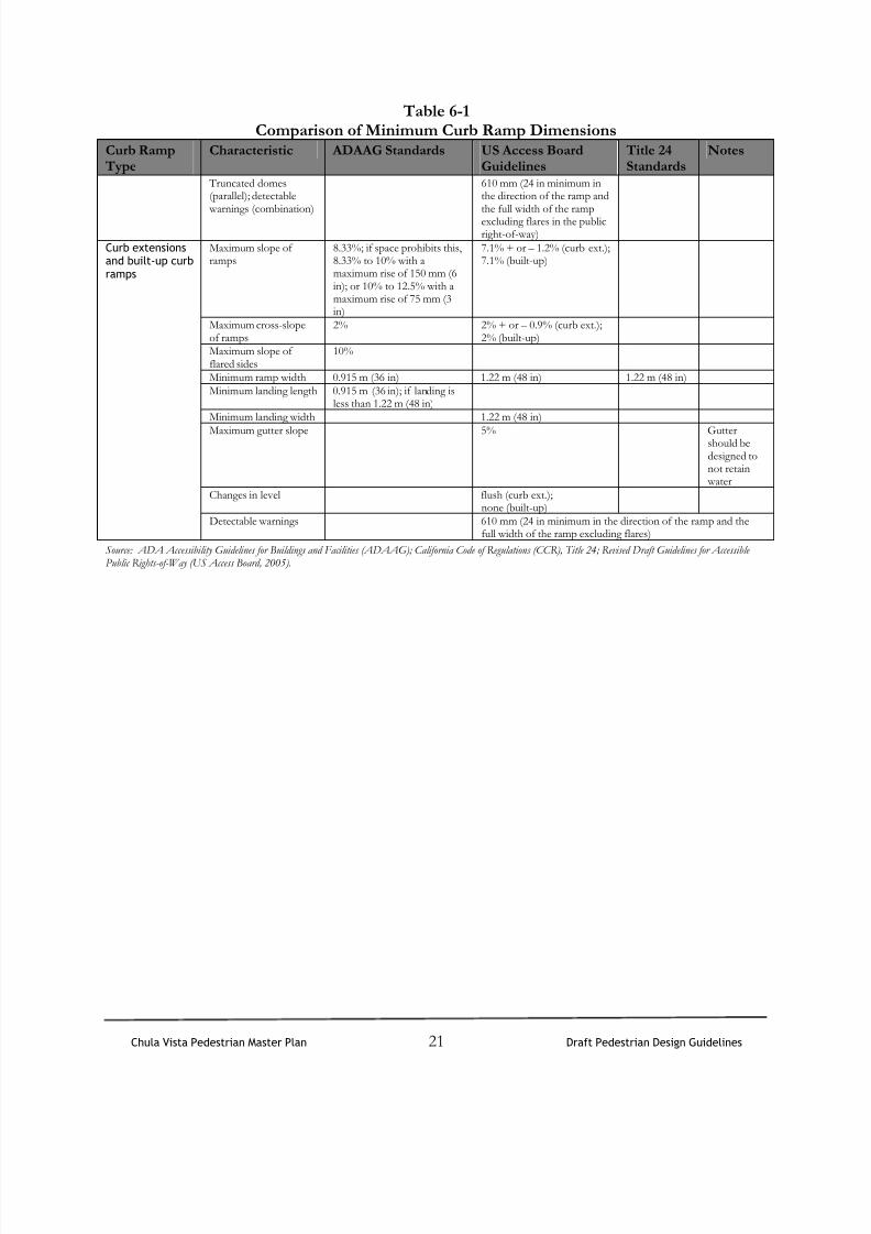
Two common curb ramp designs, perpendicular and diagonal, and the situations in which each shouldbe used, are described in Sections 6.2 and 6.3. Table 6-1 provides a comparison of various accessiblecurb ramp design standards, including parallel and curb extensions.
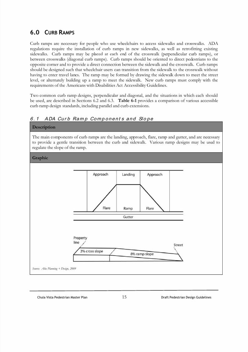
6 . 1 ADA Cu r b Ram p Comp onen t s and Sl o pe
Description
The main components of curb ramps are the landing, approach, flare, ramp and gutter, and are necessaryto provide a gentle transition between the curb and sidewalk. Various ramp designs may be used toregulate the slope of the ramp.
Graphic
Source: Alta Planning + Design, 2009

8/11/2019 Pedestrian Design Guidelines.pdf
http://slidepdf.com/reader/full/pedestrian-design-guidelinespdf 18/50
Chula Vista Pedestrian Master Plan 16 Draft Pedestrian Design Guidelines
Potential Applications
All intersections.
Midblock crossings.
Multi-use trail and roadway intersections
Details
Curb ramps should be designed to accommodate the level of use anticipated at specific locations, withsufficient width for the expected level of peak hour pedestrian volumes and other potential users. Adequate drainage should be provided to prevent flooding of curb ramps. Tactile strips must be used toassist sight-impaired pedestrians in locating the curb ramp. The following list presents definitions of themain components of curb ramps:
Landing: The level area at the top of a curb ramp facing the ramp path. Landings allow wheelchairs toenter and exit a curb ramp, as well as travel along with sidewalk without tipping or tilting.
Approach: The portion of the sidewalk on either side of the landing. Approaches provide space for wheelchairs to prepare to enter landings.
Flare: The sloped transition between the curb and sidewalk. Flares provide a sloped transition betweenthe sidewalk and curb ramp to help to prevent pedestrians from tripping over an abrupt change in level.
Ramp: The sloped transition between the sidewalk and street where the grade is constant and crossslope at a minimum. Ramps are the main pathway between the sidewalk and street.
Gutter: The trough that runs between the curb or curb ramp and the street, designed to serve as aconduit for storm water flow or other drainage.

8/11/2019 Pedestrian Design Guidelines.pdf
http://slidepdf.com/reader/full/pedestrian-design-guidelinespdf 19/50
Chula Vista Pedestrian Master Plan 17 Draft Pedestrian Design Guidelines
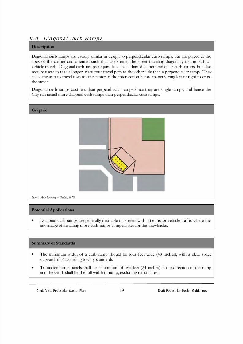
6 . 2 Pe r p e n d i c u l a r Cu r b Ramp s
Description
Perpendicular curb ramps are preferred because they allow for a convenient, direct path of travel with
a 90-degree angle to the curb. Perpendicular curb ramps are oriented such that users enter the streettraveling perpendicular to vehicular traffic. Perpendicular curb ramps maximize access for pedestriansat intersections. They reduce the overall distance required to cross the street when compared withdiagonal ramps. However, perpendicular curb ramps require more space than single diagonal ramps.
Graphic
Source: Alta Planning + Design, 2010
Potential Applications
All intersections.
Multi-use trail and roadway intersections.
Summary of Standards
Perpendicular curb ramps should be used at large intersections. Curb ramps should be aligned withcrosswalks, unless they are installed in a retrofitting effort and are located in an area with low vehicular
traffic.
The minimum width of a curb ramp should be 48 inches per the Revised Draft Guidelines for Accessible Public Rights-of-Way.
Perpendicular curb ramps without level landings are difficult for wheelchairs to negotiate, and shouldnot be installed. Where sidewalks are narrow, there may not be space for two perpendicular curbramps and their landings. Adding curb extensions can create additional space to accommodate twoperpendicular ramps and landing areas.

8/11/2019 Pedestrian Design Guidelines.pdf
http://slidepdf.com/reader/full/pedestrian-design-guidelinespdf 20/50
Chula Vista Pedestrian Master Plan 18 Draft Pedestrian Design Guidelines
Truncated dome panels shall be a minimum of two feet (24 inches) in the direction of the ramp andthe width shall be the full width of ramp, excluding ramp flares.
8/11/2019 Pedestrian Design Guidelines.pdf
http://slidepdf.com/reader/full/pedestrian-design-guidelinespdf 21/50

8/11/2019 Pedestrian Design Guidelines.pdf
http://slidepdf.com/reader/full/pedestrian-design-guidelinespdf 22/50
Chula Vista Pedestrian Master Plan 20 Draft Pedestrian Design Guidelines
Table 6-1Comparison of Minimum Curb Ramp Dimensions
Curb Ramp Type
Characteristic ADAAG Standards US Access BoardGuidelines
Title 24Standards
Notes
Maximum slope oframps
8.33%; if space prohibits this,8.33% to 10% with amaximum rise of 150 mm (6in); or 10% to 12.5% with amaximum rise of 75 mm (3in)
7.1% + or – 1.2%
Maximum cross-slopeof ramps
2%
Maximum slope offlared sides
10%
Minimum ramp width 0.915 m (36 in) 1.22 m (48 in) 1.22 m (48 in)Minimum landing length 0.915 m (36 in); if landing is
less than 1.22 m (48 in)Minimum landing width 1.22 m (48 in)Maximum gutter slope 5% Gutter
should bedesigned tonot retain
water
Changes in level flush Truncated domes 610 mm (24 in)Maximum slope oframps
8.33%; if space prohibits this,8.33% to 10% with amaximum rise of 150 mm (6in); or 10% to 12.5% with amaximum rise of 75 mm (3in)
Maximum cross-slopeof ramps
2%
Maximum slope offlared sides
10%
Minimum ramp width 0.915 m (36 in) 1.22 m (48 in) 1.22 m (48 in)Minimum landing length 0.915 m (36 in); if landing is
less than 1.22 m (48 in)Minimum landing width 1.22 m (48 in)Maximum gutter slope 2% Gutter
should bedesigned tonot retain
waterChanges in level none
PerpendicularDiagonal
Minimum clear space 1.22 m (48 in)Maximum slope oframps
8.33%; if space prohibits this,8.33% to 10% with amaximum rise of 150 mm (6in); or 10% to 12.5% with amaximum rise of 75 mm (3in)
7.1%
Maximum cross-slopeof ramps
2%
Maximum slope offlared sides
10%
Minimum ramp width 0.915 m (36 in) 1.22 m (48 in) 1.22 m (48 in)Minimum landing length 0.915 m (36 in); if landing isless than 1.22 m (48 in)
Minimum landing width 1.22 m (48 in)Maximum landing slope 2%Maximum gutter slope 5% Gutter
should bedesigned tonot retain
water
Parallel andcombination
Changes in level none
8/11/2019 Pedestrian Design Guidelines.pdf
http://slidepdf.com/reader/full/pedestrian-design-guidelinespdf 23/50
Chula Vista Pedestrian Master Plan 21 Draft Pedestrian Design Guidelines
Table 6-1Comparison of Minimum Curb Ramp Dimensions
Curb Ramp Type
Characteristic ADAAG Standards US Access BoardGuidelines
Title 24Standards
Notes
Truncated domes(parallel); detectable
warnings (combination)
610 mm (24 in minimum inthe direction of the ramp andthe full width of the rampexcluding flares in the publicright-of-way)
Maximum slope oframps
8.33%; if space prohibits this,8.33% to 10% with amaximum rise of 150 mm (6in); or 10% to 12.5% with amaximum rise of 75 mm (3in)
7.1% + or – 1.2% (curb ext.);7.1% (built-up)
Maximum cross-slopeof ramps
2% 2% + or – 0.9% (curb ext.);2% (built-up)
Maximum slope offlared sides
10%
Minimum ramp width 0.915 m (36 in) 1.22 m (48 in) 1.22 m (48 in)Minimum landing length 0.915 m (36 in); if landing is
less than 1.22 m (48 in)Minimum landing width 1.22 m (48 in)
Maximum gutter slope 5% Guttershould bedesigned tonot retain
waterChanges in level flush (curb ext.);
none (built-up)
Curb extensionsand built-up curbramps
Detectable warnings 610 mm (24 in minimum in the direction of the ramp and thefull width of the ramp excluding flares)
Source: ADA Accessibility Guidelines for Buildings and Facilities (ADAAG); California Code of Regulations (CCR), Title 24; Revised Draft Guidelines for AccessiblePublic Rights-of-Way (US Access Board, 2005).
8/11/2019 Pedestrian Design Guidelines.pdf
http://slidepdf.com/reader/full/pedestrian-design-guidelinespdf 24/50
Chula Vista Pedestrian Master Plan 22 Draft Pedestrian Design Guidelines
7.0 R AILROAD CROSSINGS
Description
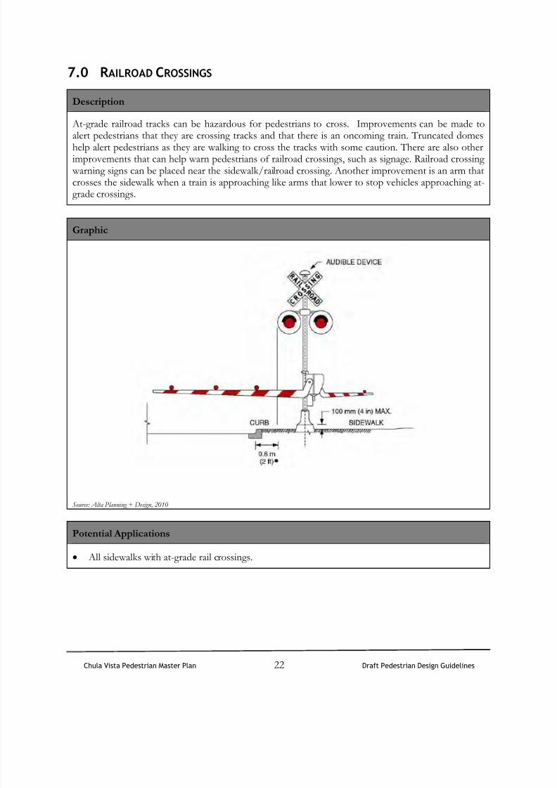
At-grade railroad tracks can be hazardous for pedestrians to cross. Improvements can be made to
alert pedestrians that they are crossing tracks and that there is an oncoming train. Truncated domeshelp alert pedestrians as they are walking to cross the tracks with some caution. There are also otherimprovements that can help warn pedestrians of railroad crossings, such as signage. Railroad crossing warning signs can be placed near the sidewalk/railroad crossing. Another improvement is an arm thatcrosses the sidewalk when a train is approaching like arms that lower to stop vehicles approaching at-grade crossings.
Graphic
Source: Alta Planning + Design, 2010
Potential Applications
All sidewalks with at-grade rail crossings.

8/11/2019 Pedestrian Design Guidelines.pdf
http://slidepdf.com/reader/full/pedestrian-design-guidelinespdf 25/50
Chula Vista Pedestrian Master Plan 23 Draft Pedestrian Design Guidelines
8.0 PEDESTRIAN AMENITIES
8 . 1 Si d ewa l k L i g ht i n g
Description
Improving street lighting makes locations appear more inviting and will encourage people to usepedestrian areas at night; which in turn, deters criminal activity.
Street lighting is designed to serve a variety of purposes. Some designers use lamp styles to provide asense of neighborhood continuity or preserve the atmosphere of an historic district. Others use lightsto improve visibility for motorists at a particular intersection. From the pedestrian’s point of view,frequent lampposts of lower height and illumination are preferred over fewer lampposts that are tallerand brighter.
Graphic Potential Applications
Source: Alta Planning + Design, 2010
Use in areas of high pedestrian activity, such asthe Village and Urban Core, where feasiblebased on available right of way, utilities andcost.
Districts with active evening use such asentertainment districts, theatres, restaurantsand parks such as the Village and Urban Core.
Summary of Standards
The Urban Core Specific Plan design guidelines recommend light fixtures above the minimum onefoot-candle illumination, that are attractive and complimentary to surrounding architecture, be used toprovide illumination around parking lots, vehicle driveways, pedestrian paths, plaza areas, and otheractivity areas.
The City has no standard for spacing pedestrian-scale lights however 40 to 60 feet apart is typicalspacing.

8/11/2019 Pedestrian Design Guidelines.pdf
http://slidepdf.com/reader/full/pedestrian-design-guidelinespdf 26/50
Chula Vista Pedestrian Master Plan 24 Draft Pedestrian Design Guidelines
8 . 2 Bi c y c l e Pa r k i n g
Description
Many errands are multi-modal, involving walking and some other transport including vehicles, transit,or bicycle. Placing bicycle parking adjacent to store fronts, shopping centers or post offices may
encourage people to bicycle to places that are too far to walk and too close for driving. To facilitate walking-bicycling trips, bicycle parking spaces can be installed in any of the zones identified except thesidewalks’ Through Passage Zone.
Graphics
Source: Alta Planning + Design, 2010
Potential Applications
Furnishing Zone of sidewalk
Frontage Zone of sidewalk. Private property owners are encouraged to provide bicycle parking foruse by the public on their land within the sidewalks’ Frontage Zone.
Summary of Standards
On narrow sidewalks, bicycle parking is oriented so the locked bicycle is parallel to the pedestrian
traffic flow. Installed in the Curb Zone, racks must be a minimum of 3.5 feet from the curb and cannot obstruct
the path of travel.
On streets with larger right-of-way, bicycle parking may be oriented with locked bicyclesperpendicular to the right-of-way as long as they do not project into the sidewalks’ ThroughPassage Zone.

8/11/2019 Pedestrian Design Guidelines.pdf
http://slidepdf.com/reader/full/pedestrian-design-guidelinespdf 27/50
Chula Vista Pedestrian Master Plan 25 Draft Pedestrian Design Guidelines
9.0 CROSSWALKS
At intersections, a crosswalk is effectively a legal extension of the sidewalk across the roadway.Crosswalks are present at all intersections, whether marked or unmarked, unless the pedestrian crossingis specifically prohibited by the City of Chula Vista. At mid-block locations, crosswalks only exist if theyare marked.
According to the California MUTCD, crosswalk markings provide guidance for pedestrians who arecrossing roadways by defining and delineating paths on approaches to and within signalizedintersections, and on approaches to other intersections where traffic stops. Crosswalk markings alsoserve to alert road users of a pedestrian crossing point across roadways not controlled by highway trafficsignals or STOP signs. At non-intersection locations, crosswalk markings legally establish the crosswalk.
As noted in the FHWA report “Safety Effects of Marked Versus Unmarked Crosswalks at UncontrolledLocations,” the California MUTCD does not provide specific guidance relative to the site condition (e.g.,traffic volume, pedestrian volume, number of lanes, presence or type of median) where markedcrosswalks should or should not be used at uncontrolled locations. Nor does the MUTCD give specificguidance on the application of crosswalk enhancement features such as high-visibility striping, advanced warning signage, or flashing beacons. While the California MUTCD allows the use of these devices,decisions on their specific applicability to a given location have historically been left to the judgment ofthe local traffic engineers.

8/11/2019 Pedestrian Design Guidelines.pdf
http://slidepdf.com/reader/full/pedestrian-design-guidelinespdf 28/50
Chula Vista Pedestrian Master Plan 26 Draft Pedestrian Design Guidelines
9 . 1 Cr o sswa l k Pl a c ement a n d Ma r k i n gs
Description
The City of Chula Vista’s standard crosswalk style is the “transverse” crosswalk, consisting of two
parallel lines. Crosswalks should extend across the full width of intersections, or to the edge of theintersecting crosswalk, to encourage pedestrians to cross perpendicular to the flow of traffic. Crosswalkmarkings can be applied with paint, or thermoplastic. At controlled crosswalk locations (STOP signs ortraffic signals), crosswalk markings by themselves are considered sufficient treatment, given thepresence of a traffic control to stop vehicles. At uncontrolled crosswalk locations (either uncontrolledintersections or mid-block locations), marked crosswalks can be enhanced with crosswalk signage,advance warning signage or flashing beacons.
The decision on whether to install standard or ladder crosswalk markings depends upon a variety offactors such as the number of pedestrians crossing, traffic speeds/volumes, number of lanes to cross,presence of nearby schools or senior centers, and history of collisions. In general, standard transversemarkings are considered appropriate at controlled intersections, minor uncontrolled intersections, andother crossing locations with low traffic volumes/speeds, short crossing distance, and good visibility.High visibility ladder markings are generally applied at uncontrolled or midblock locations, especially onmajor streets with high pedestrian volumes, heavy traffic volumes and speeds, and more than one laneeach direction.
Graphic Potential Applications
Standard crosswalk in Chula Vista
All intersections with significant pedestriantravel, including those near schools,signalized, or STOP-controlled intersections.
Summary of Standards
The width of crosswalks should be a minimum of 10 feet wide between inner crosswalk lineedges.
Crosswalk lines are 12” solid white (or yellow within school zones).

8/11/2019 Pedestrian Design Guidelines.pdf
http://slidepdf.com/reader/full/pedestrian-design-guidelinespdf 29/50
Chula Vista Pedestrian Master Plan 27 Draft Pedestrian Design Guidelines
9 . 2 Cr o sswa l k St r i p i n g a t Hi g h - V o l ume In t e r s ec t i o n s
Description
Chula Vista uses “zebra” or “ladder” crosswalks in activity areas where safety concerns are especially
high, such as around schools. In general, crosswalks at intersections should be striped in a manner thatalerts motorists to the presence of pedestrians. The striping pattern should reflect the level ofpedestrian traffic and location of the crosswalk. Ladder crosswalks should be used in high-trafficpedestrian areas, while crosswalks with parallel line striping should be used at low-traffic residentialintersections. Parallel line striping should be adequate for most signalized or stop controlledintersections, although ladder striping may be used if necessary (for example, if the site has a history ofpedestrian collisions).
Graphics
Source: Alta Planning + Design, 2009
Potential Applications
All high-volume intersections with pedestrian traffic
Summary of Standards
In locations with significant pedestrian activity, four or five mid-block crossings are present per one
street block (1320 feet wide) and may include high visibility striping.
The stripes in parallel pavement marking crosswalks should be placed 10 feet apart. In situations where the crosswalk must be narrower, the minimum distance for parallel striping is 6 feet apart.Ladder pavement markings should measure 2 foot wide by 10 foot long bars.
Continental Ladder Zebra

8/11/2019 Pedestrian Design Guidelines.pdf
http://slidepdf.com/reader/full/pedestrian-design-guidelinespdf 30/50
Chula Vista Pedestrian Master Plan 28 Draft Pedestrian Design Guidelines
9 . 3 Cr o sswa l k Ma r k i n g s i n Schoo l Z one s
Description
Crosswalks within the designated school zone must be differentiated with yellow rather than whitestriping according to California MUTCD standards, to alter motorists to the presence of schools. The
City of Chula Vista actively seeks funding, including Safe Routes to School grants, to makeinfrastructure improvements surrounding elementary schools. School safety enhancement projectsinclude high visibility yellow zebra crosswalks as well as offset medians, curb extensions, setback limitlines, and ADA-compliant pedestrian ramps and non-slip sidewalk grating.
Graphics
Crosswalk in School Zone
Potential Applications
School zones (up to 500’ in advance of the school property line)
Summary of Standards
Crosswalks can be striped as yellow standard traverse or yellow ladder or zebra crosswalks. Ladderor zebra crosswalks are preferred, particularly surrounding schools in areas with higher traffic volumes.
Special signage should also be located near school crossings in accordance with the guidelinesprovided in Chapter 7 of the California MUTCD.

8/11/2019 Pedestrian Design Guidelines.pdf
http://slidepdf.com/reader/full/pedestrian-design-guidelinespdf 31/50
Chula Vista Pedestrian Master Plan 29 Draft Pedestrian Design Guidelines
10.0 PEDESTRIAN SIGNAGE
10 . 1 Wa r n i n g Si g n age
Description
Pedestrian warning signage accompanies all pedestrian infrastructure improvements. Pedestrian warning signage may be placed on existing signposts (if appropriate) to reduce visual clutter.
At uncontrolled intersections with crosswalks, in-pavement paddles, pictured below to the left, may be warranted. These paddles are installed at the center stripe of the roadway on the leading edge of thecrosswalk. Approaching motorists are warned to yield to crossing pedestrians.
Graphic
Examples of pedestrian warning signage
Potential Applications
High pedestrian activity areas in denser urban cores and commercial districts.
Summary of Standards
Pedestrian signs should be installed according to the guidelines set forth in the CaliforniaMUTCD.
Pedestrian crossing signs (W54) should be used adjacent to all controlled pedestrian crossingareas.
One drivers-side sign is appropriate on two-lane lower speed roads.
Two signs facing each direction should be installed on roads with more than two lanes, higherspeed roads, or roadways with medians (with one sign on the median where medians exist,otherwise on the opposite side of the street).
The color of all pedestrian crossing signs should be "Fluorescent Yellow-Green" per theMUTCD. A MUTCD revision (Final Rule Docket No. 96-9, RIN 2125-AD89) adopted theoptional use of fluorescent yellow-green (FYG) for warning signs related to pedestrians, bicycle

8/11/2019 Pedestrian Design Guidelines.pdf
http://slidepdf.com/reader/full/pedestrian-design-guidelinespdf 32/50
Chula Vista Pedestrian Master Plan 30 Draft Pedestrian Design Guidelines
and school applications.
Pedestrian symbol signs (W54A) should be installed in advance of pedestrian crossings at isolatedcrossing areas. These signs are typically not used in urban areas at intersections or wheremotorists would normally expect pedestrians.
10 . 2 Schoo l Zone Si gnage
Description
Special considerations should be made for pedestrian facilities in school zones. School area signageand striping help alert motorists to be watchful for students. One way of increasing the visibility ofpedestrian-related signage is through the use of a Fluorescent Yellow-Green (FYG) background.Use of this FYG signage is approved by the California MUTCD for use on pedestrian, bicycle andschool signs. When the FYG background is used for corridor or school-area signing, a systematicapproach should be used, so that the mixing of standard yellow and fluorescent yellow-green isavoided.
Graphic
Standard School Pedestrian Signage
Source: California MUTCD
Potential Applications
All school zones.
Summary of Standards
Refer to 2006 California MUTCD for specific school zone signage types and placement standards.
8/11/2019 Pedestrian Design Guidelines.pdf
http://slidepdf.com/reader/full/pedestrian-design-guidelinespdf 33/50
Chula Vista Pedestrian Master Plan 31 Draft Pedestrian Design Guidelines
11.0 DESIGN TREATMENTS FOR CROSSWALKS
11 . 1 Cu r b Ex t e n si o n s
Description
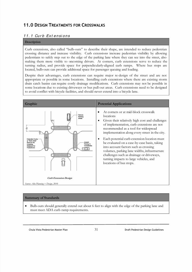
Curb extensions, also called “bulb-outs” to describe their shape, are intended to reduce pedestriancrossing distance and increase visibility. Curb extensions increase pedestrian visibility by allowingpedestrians to safely step out to the edge of the parking lane where they can see into the street, alsomaking them more visible to oncoming drivers. At corners, curb extensions serve to reduce theturning radius, and provide space for perpendicularly-aligned curb ramps. Where bus stops arelocated, bulb-outs can provide additional space for passenger queuing and loading.
Despite their advantages, curb extensions can require major re-design of the street and are notappropriate or possible in some locations. Installing curb extensions where there are existing stormdrain catch basins can require costly drainage modifications. Curb extensions may not be possible insome locations due to existing driveways or bus pull-out areas. Curb extensions need to be designedto avoid conflict with bicycle facilities, and should never extend into a bicycle lane.
Graphic Potential Applications
Curb Extension Design
Source: Alta Planning + Design, 2010
At corners or at mid-block crosswalklocations
Given their relatively high cost and challengesof implementation, curb extensions are notrecommended as a tool for widespreadimplementation along every street in the city.
Each potential curb extension location must
be evaluated on a case-by-case basis, takinginto account factors such as crossing volumes, parking lane widths, infrastructurechallenges such as drainage or driveways,turning impacts to large vehicles, andlocations of bus stops.
Summary of Standards
Bulb-outs should generally extend out about 6 feet to align with the edge of the parking lane andmust meet ADA curb ramp requirements.

8/11/2019 Pedestrian Design Guidelines.pdf
http://slidepdf.com/reader/full/pedestrian-design-guidelinespdf 34/50
Chula Vista Pedestrian Master Plan 32 Draft Pedestrian Design Guidelines
1 1 . 2 T u r n i n g Ra d i u s
Description
A corner’s turning radius determines how fast a driver can comfortably make a turn. A tighter turn orshorter radius forces drivers to slow down allowing them to see pedestrians better and stop more
quickly. Intersection corners with short radii increase safety for pedestrians at intersections bycreating more sidewalk space and less roadway space. A decreased curb radius also allows for curbramps that are aligned parallel to crosswalks.
Graphic
Source: Alta Planning + Design, 2010
Potential Applications
Two and four-way intersections.
Commercial driveways.
Summary of Standards
A 10’ turning radius is recommended for streets without curbside parking.
For streets with curbside parking, a 20’ radius is recommended.
Streets with significant volumes of truck or large vehicle traffic should be analyzed and mayrequire larger corner radii.
8/11/2019 Pedestrian Design Guidelines.pdf
http://slidepdf.com/reader/full/pedestrian-design-guidelinespdf 35/50
Chula Vista Pedestrian Master Plan 33 Draft Pedestrian Design Guidelines
11 . 3 Med i a n Re f u g e Is l a n d s
Description
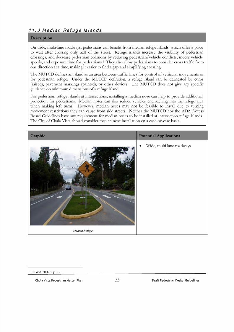
On wide, multi-lane roadways, pedestrians can benefit from median refuge islands, which offer a placeto wait after crossing only half of the street. Refuge islands increase the visibility of pedestrian
crossings, and decrease pedestrian collisions by reducing pedestrian/vehicle conflicts, motor vehiclespeeds, and exposure time for pedestrians.1 They also allow pedestrians to consider cross traffic fromone direction at a time, making it easier to find a gap and simplifying crossing.
The MUTCD defines an island as an area between traffic lanes for control of vehicular movements orfor pedestrian refuge. Under the MUTCD definition, a refuge island can be delineated by curbs(raised), pavement markings (painted), or other devices. The MUTCD does not give any specificguidance on minimum dimensions of a refuge island
For pedestrian refuge islands at intersections, installing a median nose can help to provide additionalprotection for pedestrians. Median noses can also reduce vehicles encroaching into the refuge area when making left turns. However, median noses may not be feasible to install due to turningmovement restrictions they can cause from side streets. Neither the MUTCD nor the ADA Access
Board Guidelines have any requirement for median noses to be installed at intersection refuge islands. The City of Chula Vista should consider median nose installation on a case-by-case basis.
Graphic Potential Applications
Median Refuge
Wide, multi-lane roadways
1 FHWA 2002b, p. 72

8/11/2019 Pedestrian Design Guidelines.pdf
http://slidepdf.com/reader/full/pedestrian-design-guidelinespdf 36/50
Chula Vista Pedestrian Master Plan 34 Draft Pedestrian Design Guidelines
Summary of Standards
The FHWA document “Pedestrian Accommodations at Intersections” advises that a refuge islandshould be a minimum of 4 feet wide and 12 feet long (or the width of the crosswalk, whichever isgreater).2 The ADA Access Board’s Draft Guidelines on Accessible Public Rights-of-Way has a
section on median islands.3
These guidelines have not yet been adopted, and as such are not ADArequirements at this time. However, the guidelines are under consideration for adoption in the future,and cities refer to these guidelines as best practices for compliance with future ADA standards.
The following right-of-way guidelines are recommended by the Access Board’s Draft Guidelines4:
Medians and pedestrian refuge islands in crosswalks shall contain a pedestrian access route,including passing space connecting to each crosswalk.
Regarding a minimum width for refuge islands, the guidelines state that medians andpedestrian refuge islands shall be 6.0 ft (1.8 m) minimum in length in the direction ofpedestrian travel.
The guidelines permit both ramped up and cut-through design of refuge islands, and advise
that there are many factors to consider when deciding whether to ramp or cut-through amedian or island. Those factors may include slope and cross slope of road, drainage, and width of median or island. They note that “curb ramps in medians and islands can adddifficulty to the crossing for some users.”
Medians and refuge islands are also required to have detectable warnings at cut-throughislands.
2 Pedestrian Accommodation and Intersections, FHWA,
http://safety.fhwa.dot.gov/ped_bike/univcourse/swless15.htm3 http://www.access-board.gov/PROWAC/draft.htm#3054 Access Board, Draft Accessibility Guidelines for Public Rights of Way, Section R305.4

8/11/2019 Pedestrian Design Guidelines.pdf
http://slidepdf.com/reader/full/pedestrian-design-guidelinespdf 37/50
Chula Vista Pedestrian Master Plan 35 Draft Pedestrian Design Guidelines
11 . 4 Cl o s i n g Channe l i z e d Ri g h t - T u r n Sl i p L ane s
Description
A right turn slip lane, often delineated by paint or a concrete island, separates the right turn movementfrom through and left-turning vehicles.
Slip turn lanes can present difficulties to pedestrians because drivers tend to look left and concentrateon merging with oncoming traffic and may not see pedestrians entering the crosswalk. In high-trafficareas, inadequate gaps in right-turning traffic may exist, making crossing a slip turn lane difficult forpedestrians. The non-standard corner geometry introduced by slip lanes is extremely difficult for theblind to negotiate.
The closing of a slip turn lane solves the problems discussed above and also serves to shorten thepedestrian crossing distance. Further, the area can be made an attractive corner for pedestriansthrough the use of street furniture, benches, and small-scale plantings. Where slip turns cannot beremoved due to traffic capacity considerations, several options exist for enhancing pedestrian safety.Signalizing the right turn movement creates gaps for pedestrians and may be the safest alternative.
Passive crossing treatments, such as warning signage, or a raised crosswalk connecting the sidewalk with a refuge island, may also improve conditions for pedestrians.
Graphic Potential Applications
Slip Turn Crossing Treatment
Source: Alta Planning + Design, 2010
Intersections with free turning right lanes.
Summary of Standards
Intersections’ unique geometries dictate dimensions and if a slip turn lane can be closed.

8/11/2019 Pedestrian Design Guidelines.pdf
http://slidepdf.com/reader/full/pedestrian-design-guidelinespdf 38/50
Chula Vista Pedestrian Master Plan 36 Draft Pedestrian Design Guidelines
11 . 5 Ra i s ed Si d ew a l k s
Description
The purpose of raised sidewalks is to eliminate grade changes from the pedestrian path and givepedestrians greater prominence as they cross the street.
Graphic Potential Applications
Midblock crossing with raised sidewalk
Midblock crossings.
Multi-use trail and roadway intersections.
Summary of Standards
Approaches to the raised crosswalk may be designed to be similar to speed humps.
Use detectable warnings at the curb edges to alert vision-impaired pedestrians that they areentering the roadway .

8/11/2019 Pedestrian Design Guidelines.pdf
http://slidepdf.com/reader/full/pedestrian-design-guidelinespdf 39/50
Chula Vista Pedestrian Master Plan 37 Draft Pedestrian Design Guidelines
12.0 TRAFFIC SIGNAL ENHANCEMENTS
1 2 . 1 Si g n a l T i m i n g a n d Ac t i v a t i o n
Description
Traffic signal timing can have an effect on the ability of slower-moving pedestrians to safely cross thestreet. The length of the pedestrian clearance phase is determined by calculating a clearance interval, which is the length of time it takes a person to walk from the curb on one side to the center of thefarthest travel lane on the other. The standard walking speed used to calculate pedestrian clearanceintervals recommended by the California MUTCD is 4 feet per second. The Revised Draft Guidelinesfor Accessible Public Rights-of-Way, as published by the United States Access Board, recommend apedestrian crossing speed of 3.5 feet/second for signal phase timing. Consequently, where there arepopulations of pedestrians who walk more slowly, a lower walking speed should be considered indetermining the pedestrian clearance time. Where signalized crossings are in close proximity tolocations such as senior centers, senior housing, elementary schools, or centers generating significant volume of pedestrians with disabilities, the City of Chula Vista should consider utilizing a walking
speed between 2.8 and 3.5 ft/sec to allow for longer crossing times. This recommendation may alsobe applied to locations adjacent to elementary schools, as young children commonly walk more slowly.
Fully-actuated signals are highly responsive to local traffic variations because they detect vehicles andpedestrians as they arrive in the intersection on any approach. On fully-actuated signals, pedestriansare required to push the button to actuate the WALK phase in any direction.
Potential Applications
Extended phase – At intersections with an extended phase, pedestrians who push the pedestriancrossing button get more time to cross the street than is provided during the normal signal phase.
Leading Pedestrian Interval (LPI) – At intersections where there are conflicts between turning vehicles and pedestrians, pedestrians are given a “walk” designation a few seconds before theassociated green phase for the intersection begins.
Summary of Standards
California MUTCD walking speed used to calculate pedestrian clearance intervals is 4 feet persecond.
MUTCD recommends a walking speed of 2.8 feet per second for areas with slow walkers. Allpedestrian signal placements will comply with Caltrans guidelines.

8/11/2019 Pedestrian Design Guidelines.pdf
http://slidepdf.com/reader/full/pedestrian-design-guidelinespdf 40/50
Chula Vista Pedestrian Master Plan 38 Draft Pedestrian Design Guidelines
12 . 2 Pede st r i a n Pu shbu t t o n Si g n a l s
Description
Pedestrian signals ensure that pedestrians are given adequate time to cross the roadway and are not
stranded in the crosswalk by signal lights with insufficient crossing time. Pedestrian push buttons, likethe one shown below, should be accessible to people in wheelchairs and easy to find for the sightimpaired. Depending on intersection configuration, location, and use, a variety of visual crossingindicators can be used.
One option for a pedestrian signal is a Rapid Flash LED Beacon (RFB). RFBs are experimentalpedestrian actuated signals that operate similarly to overhead beacons currently used by manyjurisdictions. What makes RFBs different is their stutter flash pattern, which is similar to that ofemergency vehicles. Preliminary tests by the FHWA have found high rates of yielding to pedestriansby drivers.
Graphics
Pedestrian pushbutton, pedestrian countdown signal, RFBSource: FHWA
Potential Applications
All high volume signalized intersections where pedestrian crossings are permitted.
Summary of Standards
Pedestrian push buttons should be located at the level top of the curb ramp cut, approximately 40inches off the ground.
Pedestrian pushbuttons should be located where sight impaired pedestrians can easily find them.
Vibrotactile pedestrian signals should be provided wherever sight-impaired pedestrians areexpected.
All pedestrian signal placements will comply with Caltrans guidelines.

8/11/2019 Pedestrian Design Guidelines.pdf
http://slidepdf.com/reader/full/pedestrian-design-guidelinespdf 41/50
Chula Vista Pedestrian Master Plan 39 Draft Pedestrian Design Guidelines
1 2 . 3 Pe d e st r i a n De t e ct i o n
Description
Trip beam actuation systems can detect pedestrians entering the crosswalk, and in the case shown
below, will trigger in-pavement flashers. Systems like this one with “passive activation” may be lessdisruptive to traffic flow, because pedestrians will usually wait for a gap in traffic before entering thecrosswalk.
Graphic
Passive activation in pavement flashers
Potential Applications
Midblock crossings with significant motor vehicle and pedestrian traffic.
Crossings with poor visibility due to the lack of lighting or other obscuration.
Summary of Standards
Not applicable on major intersections and roadways.
If specific local circumstances allow, midblock crossing treatment should be considered.
8/11/2019 Pedestrian Design Guidelines.pdf
http://slidepdf.com/reader/full/pedestrian-design-guidelinespdf 42/50
Chula Vista Pedestrian Master Plan 40 Draft Pedestrian Design Guidelines
13.0 PAVEMENT MARKINGS
13 . 1 St o p L i n e s
Description
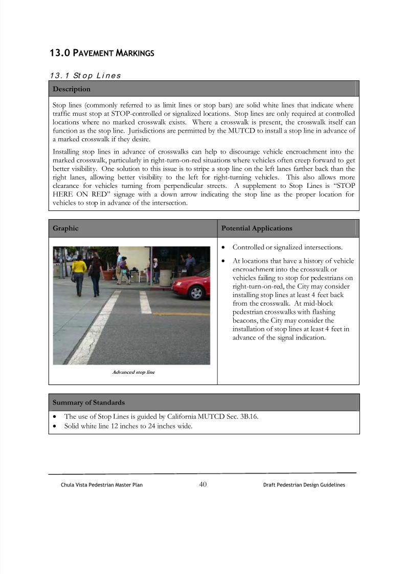
Stop lines (commonly referred to as limit lines or stop bars) are solid white lines that indicate wheretraffic must stop at STOP-controlled or signalized locations. Stop lines are only required at controlledlocations where no marked crosswalk exists. Where a crosswalk is present, the crosswalk itself canfunction as the stop line. Jurisdictions are permitted by the MUTCD to install a stop line in advance ofa marked crosswalk if they desire.
Installing stop lines in advance of crosswalks can help to discourage vehicle encroachment into themarked crosswalk, particularly in right-turn-on-red situations where vehicles often creep forward to getbetter visibility. One solution to this issue is to stripe a stop line on the left lanes farther back than theright lanes, allowing better visibility to the left for right-turning vehicles. This also allows moreclearance for vehicles turning from perpendicular streets. A supplement to Stop Lines is “STOPHERE ON RED” signage with a down arrow indicating the stop line as the proper location for
vehicles to stop in advance of the intersection.
Graphic Potential Applications
Advanced stop line
Controlled or signalized intersections.
At locations that have a history of vehicleencroachment into the crosswalk or vehicles failing to stop for pedestrians onright-turn-on-red, the City may considerinstalling stop lines at least 4 feet back
from the crosswalk. At mid-blockpedestrian crosswalks with flashingbeacons, the City may consider theinstallation of stop lines at least 4 feet inadvance of the signal indication.
Summary of Standards
The use of Stop Lines is guided by California MUTCD Sec. 3B.16.
Solid white line 12 inches to 24 inches wide.

8/11/2019 Pedestrian Design Guidelines.pdf
http://slidepdf.com/reader/full/pedestrian-design-guidelinespdf 43/50
Chula Vista Pedestrian Master Plan 41 Draft Pedestrian Design Guidelines
1 3 . 2 Y i e l d L i n e s
Description
Yield lines (also called yield teeth or shark’s teeth) indicate the point at which traffic should yield atuncontrolled locations. In California, vehicles are required to “YIELD” to pedestrians in uncontrolled
crosswalks, and yield lines can be used to indicate the appropriate location for vehicles to stop inadvance of an uncontrolled crossing location. These markings are most effective in mid-blocklocations, where there is no intersection to give a motorist cues on the location to wait for a crossingpedestrian.
Graphic
Source: Alta Planning + Design, 2010
Potential Applications
Mid-block crossing locations. On multi-lane roadways, yield lines can be used to counter the “multiple-threat” collision, which
refers to the situation where a car in one lane stops and screens the pedestrian from the view ofthe adjacent lane.
Summary of Standards
Yield line placement should be 20 to 50 feet back of uncontrolled mid-block intersections. Theuse of Yield Lines is guided by California MUTCD Sec. 3B.16.
Installing yield lines 40-50 feet back (two car lengths) gives both pedestrians and motorists a better view of each other during the crossing. “YIELD HERE FOR PEDESTRIANS” signs with a
down arrow can be used at the yield lines to indicate the proper location for vehicles to yield inadvance of the crosswalk.
White triangles are 3 feet high by 2 feet wide and spaced 1 foot apart.

8/11/2019 Pedestrian Design Guidelines.pdf
http://slidepdf.com/reader/full/pedestrian-design-guidelinespdf 44/50
Chula Vista Pedestrian Master Plan 42 Draft Pedestrian Design Guidelines
14.0 TRANSIT STOPS
Description
Bus bulb-outs can provide safe access for transit passengers and provide additional space at bus shelters
on crowded sidewalks (See the explanation of bulb-outs on page 28). Bus bulb-outs should be designedsuch that pedestrians in wheelchairs can access the bus shelter and board the bus. At transit stops where neither a bus turnout nor bus bulb-out can be accommodated, buses are often unable to pull indirectly adjacent to the curb to deploy a lift. Curb ramps in such locations allow wheelchair users toboard the bus from the street; if a bus stop is not adjacent to a corner curb ramp, a curb ramp at thebus stop should be provided. Bus shelters should also have clearly displayed bus schedules and citymaps for way-finding. Pedestrian facilities around all street furniture should meet accessibilityrequirements and pedestrian walk clearance zones.
Graphic
Source: Alta Planning + Design, 2010
Potential Applications
All transit stops.
Summary of Standards
Transit stops must make accommodation for persons with disabilities under the ADA; designs vary.

8/11/2019 Pedestrian Design Guidelines.pdf
http://slidepdf.com/reader/full/pedestrian-design-guidelinespdf 45/50
Chula Vista Pedestrian Master Plan 43 Draft Pedestrian Design Guidelines
15.0 PEDESTRIAN TRAILS
15.1 Pedestrian Trail Design
Description
Pedestrians are the most mobile trail user. They are able to walk on trails that have a variety of surfacestabilities, although compacted earth, gravel, or concrete surfaces offer the preferred level of stability. The trail design should consider the ability of the desired pedestrian. Pedestrians that use a wheelchairor other mobility assistance device require a paved surface that complies with ADA standards. Incontrast, physically fit pedestrians may require little more than a two foot clearing of semi-packedearth, though a minimum width of four feet is recommended.
The required easement for a trail can vary, but 20 feet is preferred to allow the greatest flexibility intrail placement. The minimum recommend easement width is five feet.
Graphic
Source: Alta Planning + Design, 2010
Potential Applications
Neighborhood pathways.
Summary of Standards
Four to six foot wide path.
Eight foot vertical clearance.
Grades meet 5% or less where possible. 10%maximum with terraced steps (on non-compliant ADA trails).
Cross-slopes should not exceed 8% toprevent erosion.
Gravel surface (crusher fines) orcompacted/stabilized earth.

8/11/2019 Pedestrian Design Guidelines.pdf
http://slidepdf.com/reader/full/pedestrian-design-guidelinespdf 46/50
Chula Vista Pedestrian Master Plan 44 Draft Pedestrian Design Guidelines
15.2 Multi-Use Path Design
Description
Multi-use trails along roadways provide a facility separated from the roadway with a buffer. Thesefacilities are typically preferred among recreational bicyclists who are intimidated by riding their bicycle
directly adjacent to automobile travelways. Pedestrians typically prefer separated paths over sidewalksbecause the buffer provides an added sense of safety from traveling automobiles.
A minimum of an eight foot trail width is required if bicyclists and pedestrians will be using the path. Additional width provides room for bicyclists to pass other path users. Eight foot vertical clearance isalso recommended to accommodate bicyclists. California Highway Design Manual Chapter 1000, andthe AASHTO Guide caution that multi-use paths adjacent to roadways require special considerationhowever, if well-design, can be a valuable facility for pedestrians and bicyclists.
Graphic
Multi-use path design along a roadway
Alta Planning + Design, 2010
Potential Applications
Areas with high pedestrian and bicycle demand and sufficient right-of-way.
Summary of Standards
Eight feet is the minimum allowed for a two-way multi-use path and is only recommended for lowtraffic situations.
Ten feet is recommended in most situations and will be adequate for moderate to heavy use.
Twelve feet is recommended for heavy use situations with high concentrations of multiple userssuch as joggers, bicyclists, rollerbladers and pedestrians.
Eight foot vertical clearance required, with 10 foot clearance recommended.
Vertical obstructions, such as fences and signs, adjacent to multi-purpose trails shall be a minimumof two feet from the edge of the trail to provide clear space for bicycle handlebars.

8/11/2019 Pedestrian Design Guidelines.pdf
http://slidepdf.com/reader/full/pedestrian-design-guidelinespdf 47/50
Chula Vista Pedestrian Master Plan 45 Draft Pedestrian Design Guidelines
Longitudinal grades of 5% or less, 2-3% preferred when possible.
Cross slopes of 2% or less.
Paved.
Wash crossing paved with concrete, including rock or culverts underneath, to allow water to flowunder in flood events.
Parallel swale on both side of the trail to capture runoff and create a habitat for trailside planting. Seating and interpretive features at key points along the path are desirable.

8/11/2019 Pedestrian Design Guidelines.pdf
http://slidepdf.com/reader/full/pedestrian-design-guidelinespdf 48/50
Chula Vista Pedestrian Master Plan 46 Draft Pedestrian Design Guidelines
15.3 Multi-Use Trail Intersections
Description
Paths may cross roadways either at-grade or grade-separated. At-grade crossings pose the greatest riskto path-users for encountering a conflict with automobiles. These crossings force users to wait for gapsin oncoming roadway traffic to cross, which can be uncomfortable to many users, and may evendiscourage them from using the trail. Fortunately, many roadway crossings can be designed to increasethe safety of the user and their comfort level.
Grade-separated crossings provide the most safety and comfort for the users. However, they can be very expensive. Only where other traffic control measures have failed, where there are very high volumes and speeds of traffic, or where topography lends itself, should grade-separated crossings beconsidered.
Graphic Possible Elements
Source: Alta Planning + Design, 2010
Path warning markings and warningstripe
Yield sign (MUTCD R1-2)
Striped crosswalk
Roadway markings
Mirrors to provide better sightdistances
The graphic to the left is a diagram of a
trail/path roadway crossing. Mirrorsare provided to increase the sightdistance for both the path user and themotorist. The path is marked with a warning stripe and markings before theuser approaches the roadway. Wherethe path crosses the roadway at mid-block, and no traffic controls areinstalled, a striped (ladder) crosswalkshould be used. Roadway traffic is warned of the upcoming path crossing with pavement markings and signage.
Summary of Standards
The evaluation of a roadway crossing involves analysis of vehicular traffic and trail user travelpatterns including, speeds, street width, traffic volumes (average daily traffic, peak hour traffic),line of sight, and trail user profile (age distribution and destinations).

8/11/2019 Pedestrian Design Guidelines.pdf
http://slidepdf.com/reader/full/pedestrian-design-guidelinespdf 49/50
Chula Vista Pedestrian Master Plan 47 Draft Pedestrian Design Guidelines
Roadway crossings should comply with the AASHTO Guide for the Development of BikewayFacilities and “A Policy on the Geometric Design of Highways and Streets,” and the CaliforniaMUCTD.

8/11/2019 Pedestrian Design Guidelines.pdf
http://slidepdf.com/reader/full/pedestrian-design-guidelinespdf 50/50
This page intentionally left blank