preliminary hazardous analysis
TRANSCRIPT
Preliminary Hazardous Analysis
Horsley Drive Business Park - CFC
Confidential Applicant
Document No. RCE-19113_CA_PHA_Final_4Feb20_Rev(0)
Date 4/02/2020
Confidential Applicant
Document No. RCE-19113_CA_PHA_Final_4Feb20_Rev(0)
Date 4/02/2020
ii
Preliminary Hazardous Analysis Horsley Drive Business Park - CFC
Confidential Applicant
Prepared by
Riskcon Engineering Pty Ltd Unit 19/5 Pyrmont Bridge Road Camperdown, NSW 2050 www.riskcon-eng.com ABN 74 626 753 820
© Riskcon Engineering Pty Ltd. All rights reserved.
This report has been prepared in accordance with the scope of services described in the contract or agreement between Riskcon Engineering Pty Ltd and
the Client. The report relies upon data, surveys, measurements and results taken at or under the particular times and conditions specified herein. Changes
to circumstances or facts after certain information or material has been submitted may impact on the accuracy, completeness or currency of the information
or material. This report has been prepared solely for use by the Client. Riskcon Engineering Pty Ltd accepts no responsibility for its use by other parties
without the specific authorization of Riskcon Engineering Pty Ltd. Riskcon Engineering Pty Ltd reserves the right to alter, amend, discontinue, vary or
otherwise change any information, material or service at any time without subsequent notification. All access to, or use of, the information or material is at
the user's risk and Riskcon Engineering Pty Ltd accepts no responsibility for the results of any actions taken on the basis of information or material provided,
nor for its accuracy, completeness or currency.
Confidential Applicant
Document No. RCE-19113_CA_PHA_Final_4Feb20_Rev(0)
Date 4/02/2020
iii
Quality Management Rev Date Remarks Prepared By Reviewed By
A 9 January 2020 Draft issued for comment
Jason Costa Renton Parker B 22 January 2020 Draft updated following client
review
0 4 February 2020 Final issued
Confidential Applicant
Document No. RCE-19113_CA_PHA_Final_4Feb20_Rev(0)
Date 4/02/2020
iv
Executive Summary
Background
A Confidential Applicant (CA) has proposed to develop a new automated warehouse within Horsley
Drive Business Park to be located on Cowpasture Road in Wetherill Park, NSW 2164. The
warehouse will store the suite of products typically available in in the CA ’s business for the
purposes of filling online orders for home delivery. Several of the product lines stored will contain
materials classified as Dangerous Goods (DGs).
A review of the application guide to State Environmental Planning Policy No. 33 (SEPP33, Ref. [1])
indicates the facility would exceed the threshold criteria for the storage of DGs resulting in a
classification for the site of potentially hazardous. To demonstrate that the facility is not in fact
hazardous, it is necessary to prepare a Preliminary Hazard Analysis (PHA) for the site in support
of the Development Application (DA).
FDC Construction & Fitout Pty Ltd (FDC), on behalf of the CA, has commissioned Riskcon
Engineering Pty Ltd (Riskcon) to prepare a PHA for the facility. This document represents the PHA
study for the warehouse to be located at Horsley Drive Business Park.
Conclusions
A hazard identification table was developed for warehouse facility to identify potential hazards that
may be present at the site as a result of operations or storage of materials. Based on the identified
hazards, scenarios were postulated that may result in an incident with a potential for offsite impacts.
Postulated scenarios were discussed qualitatively and any scenarios that would not impact offsite
were eliminated from further assessment. Scenarios not eliminated were then carried forward for
consequence analysis.
Incidents carried forward for consequence analysis were assessed in detail to estimate the impact
distances. Impact distances were developed into scenario contours and overlaid onto the site
layout diagram to determine if an offsite impact would occur. The consequence analysis showed
that one of the scenarios (full warehouse fire) would impact over the site boundary and into the
adjacent land use; hence, this incident was carried forward for frequency analysis and risk
assessment.
The frequency analysis and risk assessment showed that the full warehouse fire would have a
fatality risk of 7.06 chances per million per year (pmpy) at the site boundary, with lesser risk at
further distances from the boundary. HIPAP No. 4 (Ref. [2]) publishes acceptable risk criteria at the
site boundary of 50 pmpy (for industrial sites). Therefore, the probability of a fatality from a full
warehouse fire at the site boundary is within the acceptable risk criteria.
In addition, the only incident which may result in impacts to adjacent structures was a full
warehouse fire. Due to the fire size there will be considerable smoke emitted which would obscure
the flame surface reducing the average surface emissive power (SEP) and subsequently it would
not exceed 23 kW/m2. In addition, the distance to the closest buildings is 23 m which would allow
attenuation of radiant heat from of luminous spots and would not result in sustained radiant heat
such that propagation to adjacent facilities would occur.
Review of the estate proposal indicates this development is the only contributor to the risk profile;
hence, cumulative risk is not a consideration at this stage. The cumulative risk at the site is
therefore the reported 7.06 chances pmpy which is below the 50 chances pmpy limit. Therefore,
Confidential Applicant
Document No. RCE-19113_CA_PHA_Final_4Feb20_Rev(0)
Date 4/02/2020
v
the development of the warehouse does not increase the cumulative risk of the estate to an
unacceptable level.
Based on the analysis conducted, it is concluded that the risks at the site boundary are not
considered to exceed the acceptable risk criteria; hence, the facility would only be classified as
potentially hazardous and would be permitted within the current land zoning for the site.
Recommendations
Notwithstanding the conclusions following the analysis of the facility, the following
recommendations have been made:
1. The site shall be designed to contain any spills or contaminated water from a fire incident within
the boundaries of the site.
2. The warehouse and/or site boundaries shall be capable of containing 612 m3 which may be
contained within the warehouse footprint, site stormwater pipework and any recessed docks
or other containment areas that may be present as part of the site design.
3. The civil engineers designing the site containment shall demonstrate the design is capable of
containing at least 612 m3.
4. A storm water isolation point (i.e. penstock isolation valve) shall be incorporated into the
design. The penstock shall automatically isolate the storm water system upon detection of a
fire (smoke or sprinkler activation) to prevent potentially contaminated liquids from entering the
water course.
Confidential Applicant
Document No. RCE-19113_CA_PHA_Final_4Feb20_Rev(0)
Date 4/02/2020
vi
Table of Contents Executive Summary iv
1.0 Introduction 1
1.1 Background 1 1.2 Objectives 1 1.3 Scope of Services 1
2.0 Methodology 2
2.1 Multi-Level Risk Assessment 2 2.2 Risk Assessment Study Approach 3
3.0 Site Description 4
3.1 Site Location 4 3.2 General Description 4 3.3 Warehouse Detailed Description 4 3.3.1 Administration 5 3.3.2 Decanting Stations 5 3.3.3 AS (both chilled and temperature controlled) 5 3.3.4 Tote Cleaning 6 3.3.5 Freezer 6 3.3.6 Dispatch 6 3.3.7 Ancillary areas 6 3.4 Quantities of Dangerous Goods Stored and Handled 7 3.5 Aggregate Quantity Ratio 7
4.0 Hazard Identification 10
4.1 Introduction 10 4.2 Properties of Dangerous Goods 11 4.3 Hazard Identification 12 4.4 Fire Within the Automated System 12 4.5 Full Warehouse Fire 13 4.6 Full Warehouse Fire and Toxic Smoke Emission 13 4.7 LPG Release, Ignition and Pool Fire 13 4.8 LPG Unloading Incident, Hose Rupture, LPG Release, Ignition and Jet Fire 13 4.9 LPG Release and Ignition Causing Flash Fire or Explosion 14 4.10 LPG Unloading Incident, Hose Rupture, LPG Release, Ignition and Jet Fire and Impact on LPG Delivery Tanker and BLEVE 15 4.11 LPG Unloading Incident, Hose Rupture, LPG Release, Ignition and Jet Fire and Impact on LPG Tank and BLEVE 15 4.12 Dangerous Goods Liquid Spill, Release and Environmental Incident 15 4.13 Warehouse Fire, Sprinkler Activation and Potentially Contaminated Water Release 16 4.14 Ammonia Release and Toxic Gas Dispersion 16 4.15 Diesel Tank, Damage and Release, Ignition and Fire 17 4.16 Diesel Tank, Damage and Release to Environment 17
5.0 Consequence Analysis 18
5.1 Incidents Carried Forward for Consequence Analysis 18 5.2 Fire Within the Automated System 18 5.3 Full Warehouse Fire and Radiant Heat 19 5.4 Full Warehouse Fire and Toxic Smoke Emission 20 5.5 LPG Unloading Incident, Hose Rupture, LPG Release, Ignition and Jet Fire 21 5.6 LPG Unloading Incident, Hose Rupture, LPG Release, Ignition and Jet Fire and Impact on LPG Delivery Tanker and BLEVE 22 5.7 LPG Unloading Incident, Hose Rupture, LPG Release, Ignition and Jet Fire and Impact on LPG Tank and BLEVE 23
6.0 Frequency Analysis 25
6.1 Incidents Carried Forward for Frequency Analysis 25 6.2 Probability of Failure on Demand 25 6.3 Full Warehouse Fire Frequency and Risk Assessment 25 6.4 Full Warehouse Fire and Toxic Smoke Emission Frequency and Risk Assessment 26
Confidential Applicant
Document No. RCE-19113_CA_PHA_Final_4Feb20_Rev(0)
Date 4/02/2020
vii
6.5 LPG Release and ignition and jet fire 26 6.6 LPG Unloading Incident, Hose Rupture, LPG Release, Ignition and Jet Fire and Impact on LPG Delivery Tanker and Boiling Liquid Expanding Vapour Explosion (BLEVE) 28 6.7 LPG Unloading Incident, Hose Rupture, LPG Release, Ignition and Jet Fire and Impact on LPG Tank and BLEVE 28 6.8 Total Fatality Risk 28 6.9 Comparison Against Risk Criteria 29 6.10 Cumulative Assessment 29 6.11 Cumulative Assessment 29
7.0 Conclusion and Recommendations 30
7.1 Conclusions 30 7.2 Recommendations 30
8.0 References 32
A1. Hazard Identification Table 35 B1. Incidents Assessed in Detailed Consequence Analysis 39 B2. Spreadsheet Calculator (SSC) 39 B3. Jet Fire Modelling 42 B4. BLEVE Modelling 43 B5. Fire Within Automated System 44 B6. Full Warehouse Fire 45 B7. Full Warehouse Fire and Smoke Emission 46 B8. LPG Unloading Incident, Hose Rupture, LPG Release, Ignition and Jet Fire 50 B9. LPG Unloading Incident, Hose Rupture, LPG Release, Ignition and Jet Fire and Impact on LPG Delivery Tanker and BLEVE 50 B10. LPG unloading Incident, Hose Rupture, LPG Release, Ignition and Jet Fire and Impact on LPG Tank and BLEVE 51 C1. Estimation of the Frequency of a Full Warehouse Fire 53
List of Figures
Figure 2-1: The Multi-Level Risk Assessment Approach 2
Figure 3-1: Site Location 4
Figure 3-2: Site Layout 9
Figure 5-1: Fire within the Automated System 19
Figure 5-2: Full Warehouse Fire Radiant Heat Contours 20
Figure 5-3: Impact from a Jet Fire 22
Figure 5-4: BLEVE Impact 23
Figure 6-1: Full Warehouse Fire Fault Tree 26
Figure 6-2: Jet Fire Frequency 28
List of Tables
Table 2-1: Level of Assessment PHA 2
Table 3-1: Maximum Classes and Quantities of Dangerous Goods Stored 7
Table 3-2: Major Hazard Facility Thresholds 8
Table 4-1: Properties of the Dangerous Goods and Materials Stored at the Site* 11
Table 5-1: Radiant Heat Impact Distances from an AS Fire 18
Table 5-2: Radiant Heat Impact Distances from a Full Warehouse Fire 19
Table 5-3: Concentrations of Toxic Products of Combustion from a Smoke Plume 21
Table 6-1: Failure Rate Data 27
Confidential Applicant
Document No. RCE-19113_CA_PHA_Final_4Feb20_Rev(0)
Date 4/02/2020
viii
Table 6-2: Total Fatality Risk 28
List of Appendix Figures
Appendix Figure B-1: Heat Radiation on a Target from a Cylindrical Flame 39
Appendix Figure B-2: Co-ordinate System for Gas Dispersion 47
Appendix Figure B-3: Plume Concentration and Plume Height vs Distance 49
List of Appendix Tables
Appendix Table B-1: Heat Radiation and Associated Physical Impacts 43
Appendix Table B-2: Flame Height and SEP for a Flammable Material Sprinkler Controlled Fire 44
Appendix Table B-3: Heat Radiation from a Flammable Material Sprinkler Controlled Fire 44
Appendix Table B-4: Estimation of Average Burning Rate 45
Appendix Table B-5: Heat Radiation Impacts from a Full Warehouse Fire 46
Appendix Table B-6: Pasquill’s Stability Categories 46
Appendix Table B-7: Input Data for Plume Gaussian Dispersion 47
Appendix Table B-8: Concentration of Toxic Products of Combustion in Smoke Plume 50
Confidential Applicant
Document No. RCE-19113_CA_PHA_Final_4Feb20_Rev(0)
Date 4/02/2020
ix
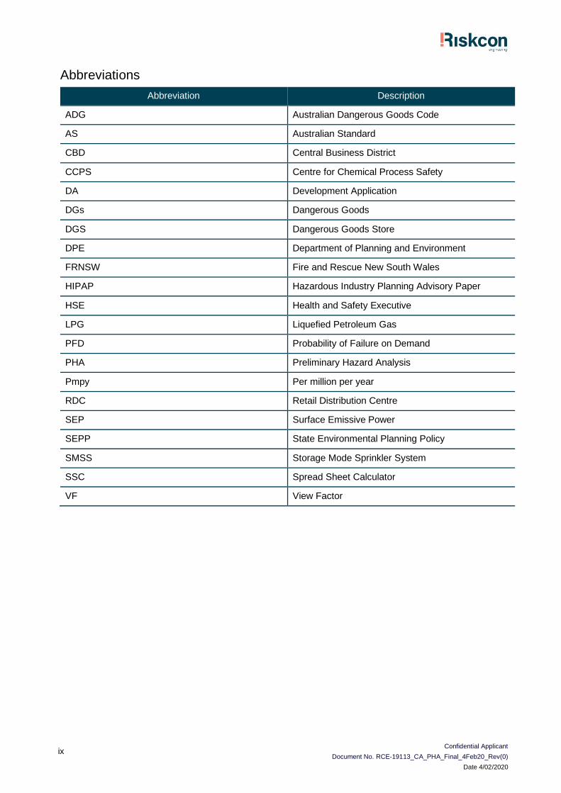
Abbreviations
Abbreviation Description
ADG Australian Dangerous Goods Code
AS Australian Standard
CBD Central Business District
CCPS Centre for Chemical Process Safety
DA Development Application
DGs Dangerous Goods
DGS Dangerous Goods Store
DPE Department of Planning and Environment
FRNSW Fire and Rescue New South Wales
HIPAP Hazardous Industry Planning Advisory Paper
HSE Health and Safety Executive
LPG Liquefied Petroleum Gas
PFD Probability of Failure on Demand
PHA Preliminary Hazard Analysis
Pmpy Per million per year
RDC Retail Distribution Centre
SEP Surface Emissive Power
SEPP State Environmental Planning Policy
SMSS Storage Mode Sprinkler System
SSC Spread Sheet Calculator
VF View Factor
Confidential Applicant
Document No. RCE-19113_CA_PHA_Final_4Feb20_Rev(0)
Date 4/02/2020
1
1.0 Introduction
1.1 Background
A Confidential Applicant (CA) has proposed to develop a new automated warehouse within Horsley
Drive Business Park to be located on Cowpasture Road in Wetherill Park, NSW 2164. The
warehouse will store the suite of products typically available in in the CA’s business for the
purposes of filling online orders for home delivery. Several of the product lines stored will contain
materials classified as Dangerous Goods (DGs).
A review of the application guide to State Environmental Planning Policy No. 33 (SEPP33, Ref. [1])
indicates the facility would exceed the threshold criteria for the storage of DGs resulting in a
classification for the site of potentially hazardous. To demonstrate that the facility is not in fact
hazardous, it is necessary to prepare a Preliminary Hazard Analysis (PHA) for the site in support
of the Development Application (DA).
FDC Construction & Fitout Pty Ltd (FDC), on behalf of the CA, has commissioned Riskcon
Engineering Pty Ltd (Riskcon) to prepare a PHA for the facility. This document represents the PHA
study for the warehouse to be located at Horsley Drive Business Park.
1.2 Objectives
The objectives of the PHA project for the proposed facility include:
• Complete the PHA according to the Hazardous Industry Planning Advisory Paper (HIPAP) No.
6 – Hazard Analysis (Ref. [3]);
• Assess the PHA results using the criteria in HIPAP No. 4 – Risk Criteria for Land Use Planning
(Ref. [2]); and
• Demonstrate compliance of the site with the relevant codes, standards and regulations (i.e.
NSW Planning and Assessment Regulation 1979, WHS Regulation, 2017 Ref. [4]).
1.3 Scope of Services
The scope of work is to complete a PHA study for the warehouse to be located at Horsley Business
Park, required by the Planning Regulations for the proposed development. The scope does not
include any other assessments at the site or any other facilities.
Confidential Applicant
Document No. RCE-19113_CA_PHA_Final_4Feb20_Rev(0)
Date 4/02/2020
2
2.0 Methodology
2.1 Multi-Level Risk Assessment
The Multi-Level Risk Assessment approach (Ref. [5]), although published by the NSW Department
of Planning and Environment, has been used as the basis for the study to determine the level of
risk assessment required. The approach considered the development in context of its location, the
quantity and type (i.e. hazardous nature) Dangerous Goods stored and used, and the facility’s
technical and safety management control. The Multi-Level Risk Assessment Guidelines are
intended to assist industry, consultants and the consent authorities to carry out and evaluate risk
assessments at an appropriate level for the facility being studied.
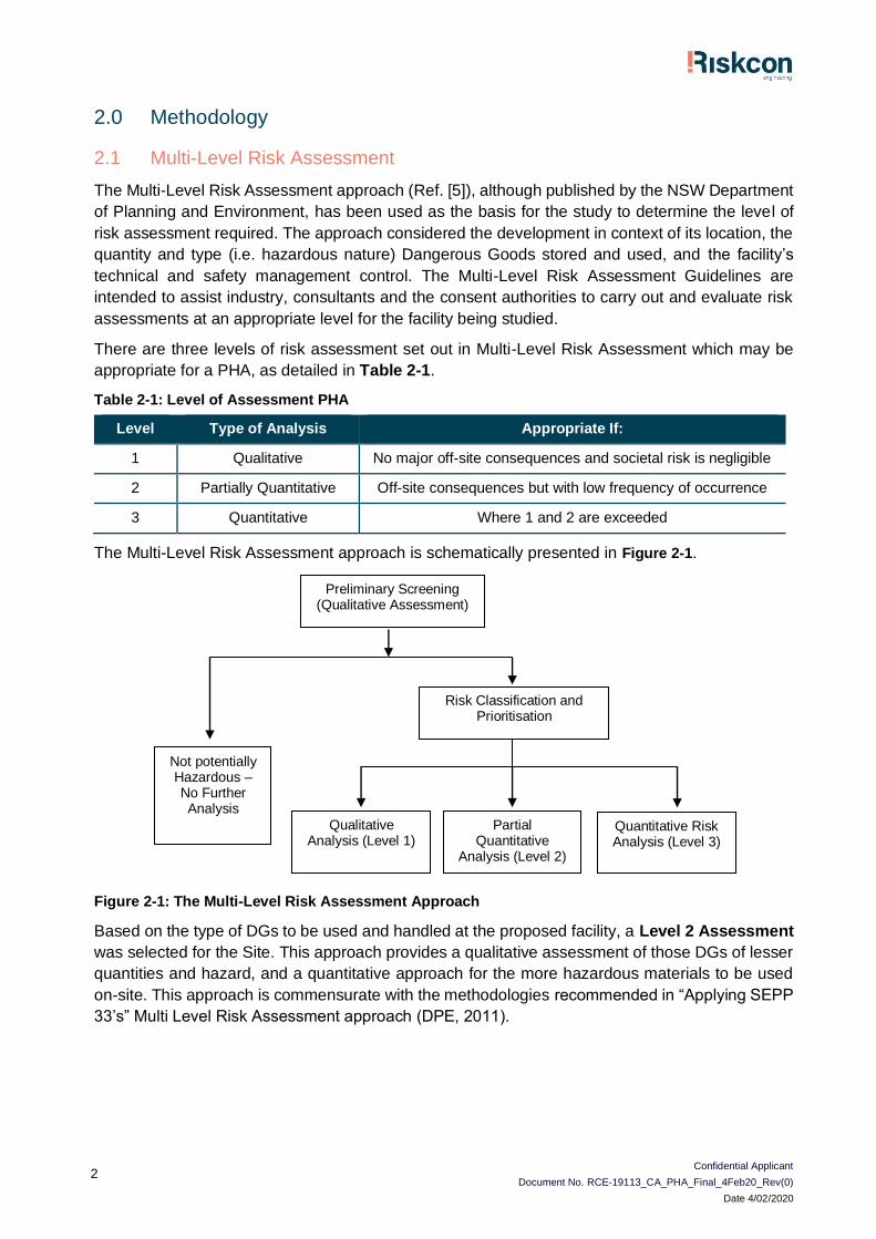
There are three levels of risk assessment set out in Multi-Level Risk Assessment which may be
appropriate for a PHA, as detailed in Table 2-1.
Table 2-1: Level of Assessment PHA
Level Type of Analysis Appropriate If:
1 Qualitative No major off-site consequences and societal risk is negligible
2 Partially Quantitative Off-site consequences but with low frequency of occurrence
3 Quantitative Where 1 and 2 are exceeded
The Multi-Level Risk Assessment approach is schematically presented in Figure 2-1.
Figure 2-1: The Multi-Level Risk Assessment Approach
Based on the type of DGs to be used and handled at the proposed facility, a Level 2 Assessment
was selected for the Site. This approach provides a qualitative assessment of those DGs of lesser
quantities and hazard, and a quantitative approach for the more hazardous materials to be used
on-site. This approach is commensurate with the methodologies recommended in “Applying SEPP
33’s” Multi Level Risk Assessment approach (DPE, 2011).
Preliminary Screening (Qualitative Assessment)
Risk Classification and Prioritisation
Not potentially Hazardous – No Further Analysis
Qualitative Analysis (Level 1)
Partial Quantitative
Analysis (Level 2)
Quantitative Risk Analysis (Level 3)
Confidential Applicant
Document No. RCE-19113_CA_PHA_Final_4Feb20_Rev(0)
Date 4/02/2020
3
2.2 Risk Assessment Study Approach
The methodology used for the PHA is as follows;
Hazard Analysis – A detailed hazard identification was conducted for the site facilities and
operations. Where an incident was identified to have a potential off-site impact, it was included in
the recorded hazard identification word diagram (Appendix A). The hazard identification word
diagram lists incident type, causes, consequences and safeguards. This was performed using the
word diagram format recommended in HIPAP No. 6 (Ref. [3]).
Each postulated hazardous incident was assessed qualitatively in light of proposed safeguards
(technical and management controls). Where a potential offsite impact was identified, the incident
was carried into the main report for further analysis. Where the qualitative review in the main report
determined that the safeguards were adequate to control the hazard, or that the consequence
would obviously have no offsite impact, no further analysis was performed. Section 3.1 of this
report provides details of values used to assist in selecting incidents required to be carried forward
for further analysis.
Consequence Analysis – For those incidents qualitatively identified in the hazard analysis to have
a potential offsite impact, a detailed consequence analysis was conducted. The analysis modelled
the various postulated hazardous incidents and determined impact distances from the incident
source. The results were compared to the consequence criteria listed in HIPAP No. 4 (Ref. [2]).
The criteria selected for screening incidents is discussed in Section 3.1.
Where an incident was identified to result in an offsite impact, it was carried forward for frequency
analysis. Where an incident was identified to not have an offsite impact, and a simple solution was
evident (i.e. move the proposed equipment further away from the boundary), the solution was
recommended, and no further analysis was performed.
Frequency Analysis – In the event a simple solution for managing consequence impacts was not
evident, each incident identified to have potential offsite impact was subjected to a frequency
analysis. The analysis considered the initiating event and probability of failure of the safeguards
(both hardware and software). The results of the frequency analysis were then carried forward to
the risk assessment and reduction stage for combination with the consequence analysis results.
Risk Assessment and Reduction – Where incidents were identified to impact offsite and where
a consequence and frequency analysis was conducted, the consequence and frequency analysis
for each incident were combined to determine the risk and then compared to the risk criteria
published in HIPAP No. 4 (Ref. [2]). Where the criteria were exceeded, a review of the major risk
contributors was performed, and the risks reassessed incorporating the recommended risk
reduction measures. Recommendations were then made regarding risk reduction measures.
Reporting – on completion of the study, a draft report was developed for review and comment. A
final report was then developed, incorporating the comments received, for submission to the
regulatory authority.
Confidential Applicant
Document No. RCE-19113_CA_PHA_Final_4Feb20_Rev(0)
Date 4/02/2020
4
3.0 Site Description
3.1 Site Location
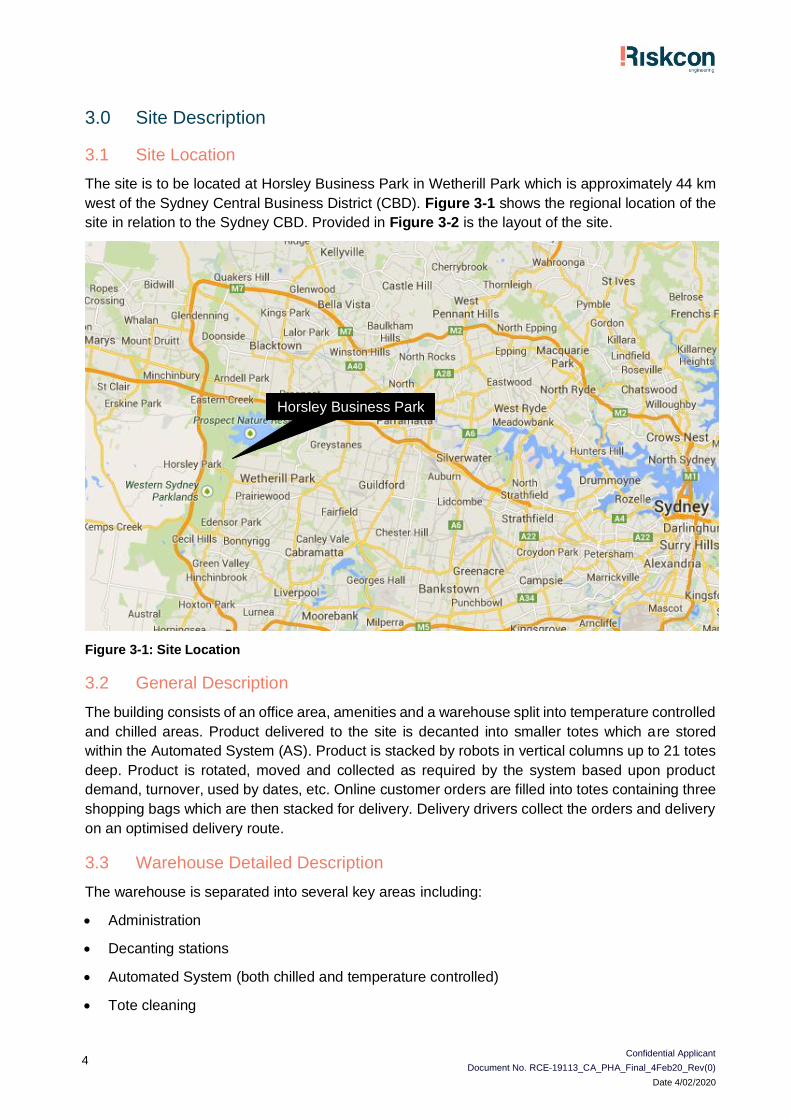
The site is to be located at Horsley Business Park in Wetherill Park which is approximately 44 km
west of the Sydney Central Business District (CBD). Figure 3-1 shows the regional location of the
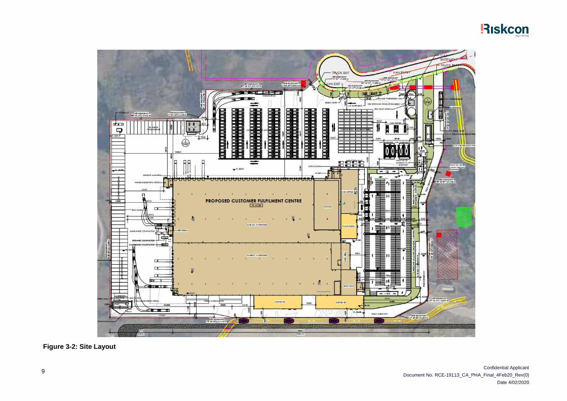
site in relation to the Sydney CBD. Provided in Figure 3-2 is the layout of the site.
Figure 3-1: Site Location
3.2 General Description
The building consists of an office area, amenities and a warehouse split into temperature controlled
and chilled areas. Product delivered to the site is decanted into smaller totes which are stored
within the Automated System (AS). Product is stacked by robots in vertical columns up to 21 totes
deep. Product is rotated, moved and collected as required by the system based upon product
demand, turnover, used by dates, etc. Online customer orders are filled into totes containing three
shopping bags which are then stacked for delivery. Delivery drivers collect the orders and delivery
on an optimised delivery route.
3.3 Warehouse Detailed Description
The warehouse is separated into several key areas including:
• Administration
• Decanting stations
• Automated System (both chilled and temperature controlled)
• Tote cleaning
Horsley Business Park
Confidential Applicant
Document No. RCE-19113_CA_PHA_Final_4Feb20_Rev(0)
Date 4/02/2020
5
• Freezer
• Dispatch
• Ancillary areas
Each area is discussed in further detail in the following subsections.
3.3.1 Administration
The administration areas operate similarly to any warehouse and include office areas, lunchrooms,
change rooms, etc.
3.3.2 Decanting Stations
The decanting stations are located on the bottom level of the structure and is manned by operators
who receive pallets of product from forklift drivers. The operators then unload the pallets, decanting
the product into specifically labelled totes ensuring the product within the tote matches the product
ID in the system. This is critical as the system tracks the product within the tote based upon used
by dates and the product itself.
Once the tote is filled it is loaded into AS where a robot, which is located on top of AS, raises the
tote up through the column and secures it beneath the robot. The robot then travels to a designated
location to store the product.
Where flammable liquid products are decanted, the tote will be lined with a metal liner to prevent
any spills from contacting the plastic tote which may dissolve the plastic. In addition, the metal tote
provides a layer of protection if a fire were to occur as the fire is contained within the tote and can
only propagate vertically rather than horizontally.
3.3.3 AS (both chilled and temperature controlled)
The AS itself is segmented into the temperature-controlled side and the chilled side. The
temperature controlled contains general chilled products stored on shelves while the chilled side
contains items such as cheeses, milk, etc.
The system is completely automated by a computer system which directs up to 600 drones which
move along east/west and north/south tracks to travel across the top of the AS. The process initially
starts with a robot collecting the tote from the decanting station. Depending upon the product type,
shelf life, turnover, seasonality, etc. the tote will be designated a location. The robot will then travel
to the coordinates of the location where it will be stored. The tote may be required to be stored at
a lower depth than the top available location. In this scenario, a “swarm” of robots will travel to the
designated location where each will remove a tote from the designated column. Once sufficient
totes have been removed to allow the subject tote to be stored, it will then be lowered into the AS.
Collected totes by the swarming robots will either be relocated or may be stored back where they
were taken from which is determined by the software.
When an order is required to be filled, the robots will collect the designated tote and delivery it back
to the decanting area where it is lowered to the upper levels of the mezzanine where product is
removed as designated by the order. Once extracted, the totes I then reloaded back into the AS
for collection by the robots and storage.
The AS also has opportunity charging locations around the outside of the AS where robots may
charge when running low on battery or when the robot isn’t required immediately for relocation
Confidential Applicant
Document No. RCE-19113_CA_PHA_Final_4Feb20_Rev(0)
Date 4/02/2020
6
operations. The robots park in the charging location where contactors charge the battery until the
robot is required for use.
Due to the nature of the storage, sprinklers can’t be provided within the system; hence, the AS is
protected by a ceiling mounted sprinkler system which has been designed by FM Global in
association with the manufacturer specifically for the range of products and tote materials used
within the AS.
3.3.4 Tote Cleaning
Totes may become dirty due to spilled product or during transport to customers which must be
cleaned prior to reuse. The tote cleaning area is an automated washing machine style cleaner
using detergents and water to clean the totes which are then dried ready for reuse in the system.
3.3.5 Freezer
The freezer is not an automated area of the warehouse and is established as a normal retail store
except instead of the store containing freezers with doors, the whole space is a freezer and product
is stored on shelves. As personnel pick the orders, they walk through the aisles of the freezer
collecting product as dictated by the customer order. Once completed, product is stacked into
chiller boxes along with dry ice to keep the product cool.
3.3.6 Dispatch
The dispatch area is located in the chiller side of the warehouse where filled totes are stored prior
to dispatch. Totes are stored based upon the intended delivery location with orders along a similar
route / suburb are stored to maximise efficiency.
3.3.7 Ancillary areas
Ancillary areas include, but are not limited to:
• Forklift charging
• Technical space
• Refrigeration
These areas are further discussed in the following subsections.
3.3.7.1 Forklift Charging
The charging areas are designed as opportunity charging locations to charge the forklifts quickly
when there is downtime. This allows the forklifts to remain in constant use throughout a shift without
being required to sit idle during a dedicated charge. The charging locations are spread throughout
the warehouse area.
3.3.7.2 Technical Space
The technical space is associated with the top of the AS and is where the engineers that ensure
the robots are operating correctly are housed. Robot maintenance or robot retrieval during break
downs occurs from this area.
Confidential Applicant
Document No. RCE-19113_CA_PHA_Final_4Feb20_Rev(0)
Date 4/02/2020
7
3.3.7.3 Refrigeration
The refrigeration system will be a combined glycol/ammonia system where ammonia is used in the
refrigeration system extracting heat from the glycol system which is transported to the chiller and
freezer areas. Heat is absorbed from these areas by the glycol which is transported back to the
refrigeration system to discharge the heat to atmosphere.
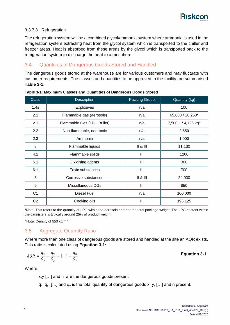
3.4 Quantities of Dangerous Goods Stored and Handled
The dangerous goods stored at the warehouse are for various customers and may fluctuate with
customer requirements. The classes and quantities to be approved in the facility are summarised
Table 3-1.
Table 3-1: Maximum Classes and Quantities of Dangerous Goods Stored
Class Description Packing Group Quantity (kg)
1.4s Explosives n/a 100
2.1 Flammable gas (aerosols) n/a 65,000 / 16,250*
2.1 Flammable Gas (LPG Bullet) n/a 7,500 L / 4,125 kg^
2.2 Non-flammable, non-toxic n/a 2,650
2.3 Ammonia n/a 1,000
3 Flammable liquids II & III 11,130
4.1 Flammable solids III 1200
5.1 Oxidising agents III 300
6.1 Toxic substances III 700
8 Corrosive substances II & III 24,000
9 Miscellaneous DGs III 850
C1 Diesel Fuel n/a 100,000
C2 Cooking oils III 195,125
*Note: This refers to the quantity of LPG within the aerosols and not the total package weight. The LPG content within
the cannisters is typically around 25% of product weight.
^Note: Density of 550 kg/m3
3.5 Aggregate Quantity Ratio
Where more than one class of dangerous goods are stored and handled at the site an AQR exists.
This ratio is calculated using Equation 3-1:
𝐴𝑄𝑅 =𝑞𝑥
𝑄𝑥+
𝑞𝑦
𝑄𝑦+ [… ] +
𝑞𝑛
𝑄𝑛
Equation 3-1
Where:
x,y […] and n are the dangerous goods present
qx, qy, […] and qn is the total quantity of dangerous goods x, y, […] and n present.
Confidential Applicant
Document No. RCE-19113_CA_PHA_Final_4Feb20_Rev(0)
Date 4/02/2020
8
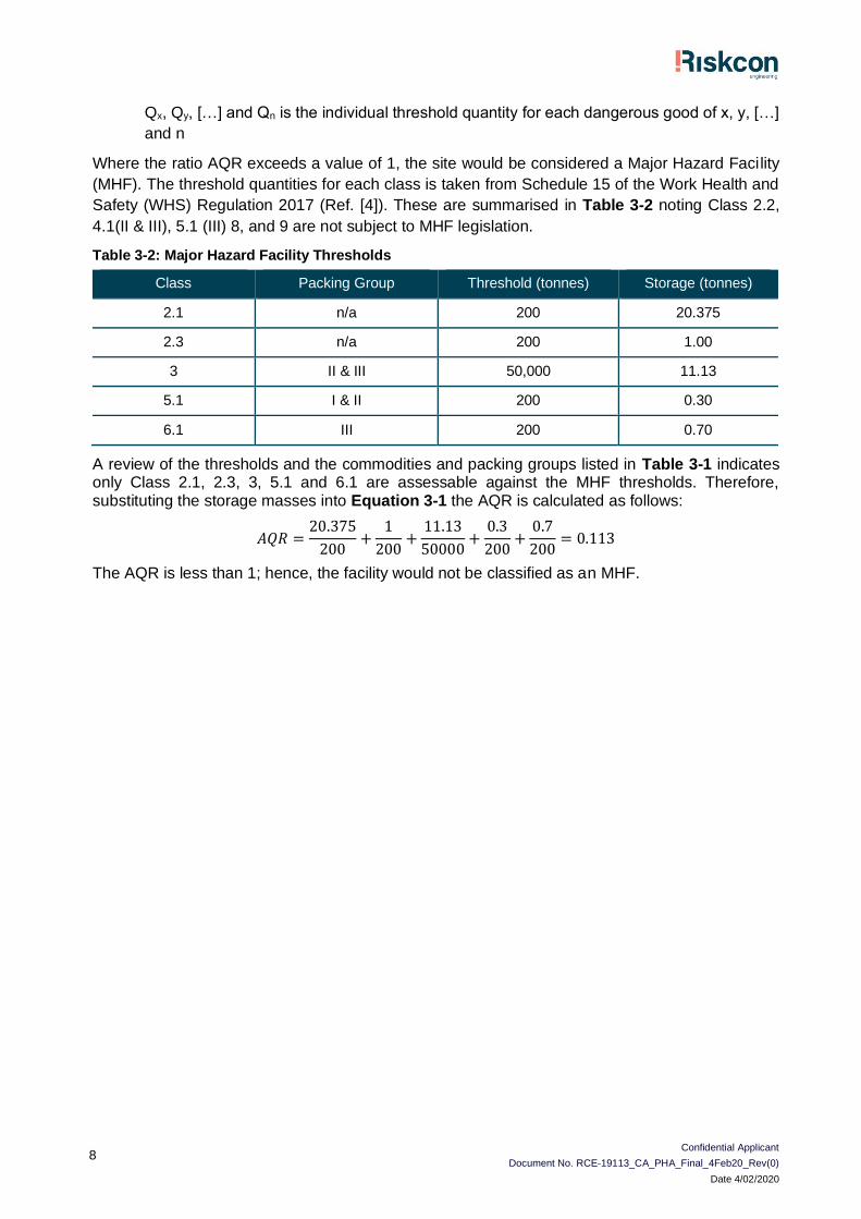
Qx, Qy, […] and Qn is the individual threshold quantity for each dangerous good of x, y, […]
and n
Where the ratio AQR exceeds a value of 1, the site would be considered a Major Hazard Facility
(MHF). The threshold quantities for each class is taken from Schedule 15 of the Work Health and
Safety (WHS) Regulation 2017 (Ref. [4]). These are summarised in Table 3-2 noting Class 2.2,
4.1(II & III), 5.1 (III) 8, and 9 are not subject to MHF legislation.
Table 3-2: Major Hazard Facility Thresholds
Class Packing Group Threshold (tonnes) Storage (tonnes)
2.1 n/a 200 20.375
2.3 n/a 200 1.00
3 II & III 50,000 11.13
5.1 I & II 200 0.30
6.1 III 200 0.70
A review of the thresholds and the commodities and packing groups listed in Table 3-1 indicates only Class 2.1, 2.3, 3, 5.1 and 6.1 are assessable against the MHF thresholds. Therefore, substituting the storage masses into Equation 3-1 the AQR is calculated as follows:
𝐴𝑄𝑅 =20.375
200+
1
200+
11.13
50000+
0.3
200+
0.7
200= 0.113
The AQR is less than 1; hence, the facility would not be classified as an MHF.
Confidential Applicant
Document No. RCE-19113_CA_PHA_Final_4Feb20_Rev(0)
Date 4/02/2020
9
Figure 3-2: Site Layout
Confidential Applicant
Document No. RCE-19113_CA_PHA_Final_4Feb20_Rev(0)
Date 4/02/2020
10
4.0 Hazard Identification
4.1 Introduction
A hazard identification table has been developed and is presented at Appendix A. This table has
been developed following the recommended approach in Hazardous Industry Planning Advisory
Paper No. 6, Hazard Analysis Guidelines (Ref. [3]). The Hazard Identification Table provides a
summary of the potential hazards, consequences and safeguards at the site. The table has been
used to identify the hazards for further assessment in this section of the study. Each hazard is
identified in detail and no hazards have been eliminated from assessment by qualitative risk
assessment prior to detailed hazard assessment in this section of the study.
In order to determine acceptable impact criteria for incidents that would not be considered for
further analysis, due to limited impact offsite, the following approach has been applied:
• Fire Impacts - It is noted in Hazardous Industry Planning Advisory Paper (HIPAP) No. 4 (Ref.
[2]) that a criterion is provided for the maximum permissible heat radiation at the site boundary
(4.7 kW/m2) above which the risk of injury may occur and therefore the risk must be assessed.
Hence, to assist in screening those incidents that do not pose a significant risk, for this study,
incidents that result in a heat radiation less that at 4.7 kW/m2, at the site boundary, are screened
from further assessment.
Those incidents exceeding 4.7 kW/m2 at the site boundary are carried forward for further
assessment (i.e. frequency and risk). This is a conservative approach, as HIPAP No. 4 (Ref.
[2]) indicates that values of heat radiation of 4.7 kW/m2 should not exceed 50 chances per
million per year at sensitive land uses (e.g. residential). It is noted that the closest residential
area is more than several hundred meters from the site, hence, by selecting 4.7 kW/m2 as the
consequence impact criteria (at the adjacent industrial site boundary) the assessment is
considered conservative.
• Explosion - It is noted in HIPAP No. 4 (Ref. [2]) that a criterion is provided for the maximum
permissible explosion over pressure at the site boundary (7 kPa) above which the risk of injury
may occur and therefore the risk must be assessed. Hence, to assist in screening those
incidents that do not pose a significant risk, for this study, incidents that result in an explosion
overpressure less than 7 kPa, at the site boundary, are screened from further assessment.
Those incidents exceeding 7 kPa, at the site boundary, are carried forward for further
assessment (i.e. frequency and risk). Similarly, to the heat radiation impact discussed above,
this is conservative as the 7 kPa value listed in HIPAP No. 4 relates to residential areas, which
are over more than several hundred meters from the site.
• Toxicity – No toxic gases have been proposed to be stored at the site; hence, toxicity has not
been assessed in this study.
• Property Damage and Accident Propagation - It is noted in HIPAP No. 4 (Ref. [2]) that a criterion
is provided for the maximum permissible heat radiation/explosion overpressure at the site
boundary (23 kW/m2/14 kPa) above which the risk of property damage and accident
propagation to neighbouring sites must be assessed. Hence, to assist in screening those
incidents that do not pose a significant risk to incident propagation, for this study, incidents that
result in a heat radiation heat radiation less than 23 kW/m2 and explosion over pressure less
than 14 kPa, at the site boundary, are screened from further assessment. Those incidents
Confidential Applicant
Document No. RCE-19113_CA_PHA_Final_4Feb20_Rev(0)
Date 4/02/2020
11
exceeding 23 kW/m2 at the site boundary are carried forward for further assessment with
respect to incident propagation (i.e. frequency and risk).
• Societal Risk – HIPAP No. 4 (Ref. [2]) discusses the application of societal risk to populations
surrounding the proposed potentially hazardous facility. It is noted that HIPAP No. 4 indicates
that where a development proposal involves a significant intensification of population, in the
vicinity of such a facility, the change in societal risk needs to be taken into account. In the case
of the facility, there is currently no significant intensification of population around the proposed
site; however, the adjacent land has been rezoned residential; hence, there will be housing
located approximately more than several hundred meters from the site. Therefore, societal risk
has been considered in the assessment.
4.2 Properties of Dangerous Goods
The type of DGs and quantities stored and used at the site has been described in Section 3. Table
4-1 provides a description of the DGs stored and handled at the site, including the Class and the
hazardous material properties of the DG Class.
Table 4-1: Properties of the Dangerous Goods and Materials Stored at the Site*
Class Hazardous Properties
2.1 – Flammable
Gas
Class 2.1 includes flammable gases which are ignitable when in a mixture of 13 per
cent or less by volume with air or have a flammable range with air of at least 12
percentage points regardless of the lower flammable limit. Ignited gas may result in
explosion or flash fire. Where gas released under pressure from a hole in a
pressurised component is ignited, a jet fire may occur.
2.2 – Non-
Flammable, Non-
Toxic Gases
Class 2.2 includes non-flammable and non-toxic gases which are asphyxiant (dilute
or replace the oxygen normally in the atmosphere).
3 – Flammable
Liquids
Class 3 includes flammable liquids which are liquids, or mixtures of liquids, or
liquids containing solids in solution or suspension (for example, paints, varnishes,
lacquers, etc.) which give off a flammable vapour at temperatures of not more than
60oC closed-cup test or not more than 65.6oC open-cup test. Vapours released may
mix with air and if ignited, at the right, concentration will burn resulting in pool fires
at the liquid surface.
4.1 – Flammable
Solids
Flammable solid materials are materials that may burn when exposed to an ignition
source, examples of flammable solids include matches and some waxes.
5.1 -Oxidising
Agents
Class 5.1 materials will not combust but these materials include substances which
can in a fire event, liberate oxygen and could accelerate the burning of other
combustible or flammable materials. Releases to the environment may cause
damage to sensitive receptors within the environment.
6.1 – Toxic
Substances
Substances liable either to cause death or serious injury or to harm human health if
swallowed or inhaled or by skin contact.
8 – Corrosive
Substances
Class 8 substances (corrosive substances) are substances which, by chemical
action, could cause damage when in contact with living tissue (i.e. necrosis), or, in
case of leakage, may materially damage, or even destroy, other goods which come
into contact with the leaked corrosive material. Releases to the environment may
cause damage to sensitive receptors within the environment.
Confidential Applicant
Document No. RCE-19113_CA_PHA_Final_4Feb20_Rev(0)
Date 4/02/2020
12
Class Hazardous Properties
9 – Miscellaneous
DGs
Class 9 substances and articles (miscellaneous dangerous substances and
articles) are substances and articles which, during transport present a danger not
covered by other classes. Releases to the environment may cause damage to
sensitive receptors within the environment.
* The Australian Code for the Transport of Dangerous Goods by Road and Rail (Ref. [6]
4.3 Hazard Identification
Based on the hazard identification table presented in Appendix A, the following hazardous scenarios have been developed:
• Fire within the Automated System.
• Full warehouse fire.
• Full warehouse fire and toxic smoke emission.
• LPG release, ignition and pool fire.
• LPG unloading incident, hose rupture, LPG release, ignition and jet fire.
• LPG release and ignition causing flash fire or explosion.
• LPG unloading incident, hose rupture, LPG release, ignition and jet fire and impact on LPG
delivery tanker and Boiling Liquid Expanding Vapour Explosion (BLEVE).
• LPG unloading incident, hose rupture, LPG release, ignition and jet fire and impact on LPG tank
and BLEVE.
• Dangerous goods liquid spill, release and environmental incident.
• Warehouse fire, sprinkler activation and potentially contaminated water release.
• Ammonia release and toxic gas dispersion.
• Diesel tank, damage and release, ignition and fire.
• Diesel tank, damage and release to environment.
Each identified scenario is discussed in further detail in the following sections.
4.4 Fire Within the Automated System
The Automated System (AS) will contain a range of mixed products including DG products which
are stored in totes and shuffled through the AS via overhead robotic units. The totes are composed
of plastic PPE and are fully enclosed on all sides except for the top. The enclosed nature of the
totes will prevent any spills within a tote from impacting packages in adjacent totes.
Notwithstanding this, there is always the potential that a release could occur and could be ignited
(i.e. static). If this were to occur the fire would initially be small and would likely smoulder for some
time as oxygen availability is restricted due to the tight spacing between totes both laterally and
vertically. However, as heat accumulates it will impact adjacent totes which will begin to heat up
transferring heat into the plastic totes which may heat up and begin to melt, smoulder, or ignite.
As the spacing is tight within the AS, the fire will likely take a substantial time to develop which will
also prevent activation of the overhead sprinkler system. However, as the fire will likely progress

Confidential Applicant
Document No. RCE-19113_CA_PHA_Final_4Feb20_Rev(0)
Date 4/02/2020
13
slowly in a low oxygen environment black smoke will be generated which will alert operators to the
presence of a fire who can alert Fire & Rescue NSW (FRNSW) to attend the site to control fire
growth.
While it is anticipated the fire will progress slowly based on a smouldering fire growth it could
progress quickly given the fire risks associated with these types of store are relatively unknown as
these products are only entering the market. Therefore, for the purposes of modelling the risk, it
must be assumed that the fire can grow throughout the AS as the close packed nature of the store
will prevent the overhead sprinklers from extinguishing fire in the base. Therefore, this incident has
been carried forward for further analysis.
As the fire grows, the SMSS is expected to activate to suppress the fire and cool adjacent packages
to minimise the potential for aerosol rupture. Activation of this system would control the fire within
the sprinkler array. A sprinkler-controlled fire within the AS would be unlikely to impact over the site
boundary; notwithstanding this, this incident has been carried forward for consequence analysis.
4.5 Full Warehouse Fire
There is potential that if a fire occurred and the fire protection systems failed to activate, a small
fire may escalate as radiant heat impacts adjacent packages resulting in deterioration and release
of additional fuel. While it is considered unlikely for a fire to occur simultaneously with the sprinkler
system failing to operate there is the potential for this scenario to occur. Therefore, this incident
has been carried forward for further analysis.
4.6 Full Warehouse Fire and Toxic Smoke Emission
As discussed in Section 4.5 there is the potential for a full warehouse fire to occur in the event of
sprinkler failure. During combustion toxic products of combustion may be generated which will be
dispersed in the smoke plume which may impact downwind from the site. Depending on the toxicity
of the biproducts, this may result in injury or fatality. Therefore, this incident has been carried
forward for further analysis.
4.7 LPG Release, Ignition and Pool Fire
In the event of a small leak from a vessel or pipework a pool of LPG may form when the rate of
evaporation of LPG is less than the flow rate of LPG from the leak. If the pool were to ignite an LPG
pool fire would occur which may impact over the site boundary.
A leak sufficient to cause a release that exceeds the evaporation rate to develop a pool large
enough to ignite (noting the area is zoned per the requirements of AS/NZS 60079.10.1:2009, Ref.
[7]) and the subsequent fire to impact over the site boundary is very low. This is substantiated by
numerous similar sized LPG tanks installed throughout Australia with very low incidences of leaks
and fires occurring from such installations.
As the potential for a leak and LPG pool and subsequent ignition to occur is incredibly low, this
incident has not been carried forward for further analysis.
4.8 LPG Unloading Incident, Hose Rupture, LPG Release, Ignition and Jet Fire
As the site LPG is depleted, it will be refilled by a delivery tanker at the site. During loading of the
tank there is the potential for the hose to rupture which may be the result of a puncture of the hosing
or deterioration through general wear and tear. It has been assumed the hoses are inspected

Confidential Applicant
Document No. RCE-19113_CA_PHA_Final_4Feb20_Rev(0)
Date 4/02/2020
14
monthly and pressure tested annually in accordance with the Australian Dangerous Goods Code
(ADG, Ref. [8]).
Notwithstanding this, there is the potential for a hose to become damaged between inspection and
test periods which may lead to sufficient deterioration resulting in a hose rupture when transferring
pressurised LPG. Excess flow and non-return valves will isolate the flow of LPG; however, if these
fail in addition to a hose rupture, LPG will be released resulting in an LPG vapour cloud. The
operator may be able to respond and isolate the LPG transfer by activating an emergency stop
button located on the tanker.
If the operator is incapacitated or unable to stop the transfer, the LPG will continue to flow
developing a substantial cloud which may contact an ignition source and ignite which would result
in a flash fire or explosion which would burn back to the release point and subsequent jet fire. It is
noted the area is unconfined; hence, an explosion is unlikely to occur and would likely result in a
flash fire.
The potential for a fatality to occur as a result of a flash fire is not considered credible as the
mechanism for a fatality to occur from a flash fire is via combustion of flammable vapours at head
height which results in oxygen within the lungs being consumed as the fuel burns. The impacted
person will involuntarily inhale, as low oxygen is detected, resulting in inhalation of hot combustion
products which burn the sensitive lining of the lungs. As LPG is a dense gas, any release will
spread along at ground level and due to the open nature of the site it will not accumulate to a level
where a person offsite will be fully engulfed; hence, a fatality is unlikely to occur.
While a flash fire may not be expected to cause significant harm, the impacts from a jet fire are
likely to be substantial and would impact over the site boundary; hence, this incident has been
carried forward for further analysis.
4.9 LPG Release and Ignition Causing Flash Fire or Explosion
In the event of an LPG release, LPG will vaporise forming a flammable atmosphere which may
ignite. A review of the area indicates the tank will not be stored in an area where confinement will
occur; hence, the atmosphere would not ignite as an explosion but would rather result in a flash
fire.
As noted in Section 4.8, the mechanism for a fatality to occur from a flash fire is inhalation of hot
combustion products when a person is fully engulfed in a vapour cloud when ignition occurs. As
LPG is a dense gas it will spread out at ground level as there is no confinement to allow the gas to
accumulate at height; therefore, it is unlikely that a vapour cloud would form to allow a person to
be fully engulfed; hence, a fatality would be unlikely to occur.
Furthermore, AS/NZS 1596:2014 (Ref. [9]) has been developed with reference to the likely impact
scenarios from storage of LPG in various tank sizes. Review of Table 6.1 of AS/NZS 1596:2014
(Ref. [9]) indicates for a 7.5 kL tank the separation distance to a protected place is approximately
6 m. Therefore, the standard would consider that in open air, events resulting from a release from
the tank would be unlikely to significantly impact >6 m.
A catastrophic failure of an LPG tank (i.e. rupture and full release of LPG) is considered incredible
due to the manufacturing and regular testing of pressure vessels according to AS 1210:2010 (Ref.
[10]).
Confidential Applicant
Document No. RCE-19113_CA_PHA_Final_4Feb20_Rev(0)
Date 4/02/2020
15
As the area is unconfined and the location of the tank provides adequate separation to the site
boundary and protected places it is considered that a fatality would not result from this incident;
hence, this incident has not been carried forward for further analysis.
4.10 LPG Unloading Incident, Hose Rupture, LPG Release, Ignition and Jet Fire
and Impact on LPG Delivery Tanker and BLEVE
Similarly, to the scenario described in Section 4.9 the hose may rupture resulting in a jet fire. If this
jet fire were aimed at the delivery tanker, the tanker shell would begin to heat, transferring the heat
into the LPG within the tank which would begin to vaporise and increase the pressure within the
tanker. At the design pressure of the tank, the pressure relief valve will begin to lift to relieve
pressure within the tanker.
As the liquid level within the tanker drops, the impact zone of the jet fire may impact the vapour
space in the tanker. The vapour will absorb less energy than the liquid which will result in localised
heating of the tanker shell at the point of the jet fire impact. This may compromise the structural
integrity of the tanker shell which may rupture resulting in a blast overpressure as the vessel fails
and formation of an LPG vapour cloud which may also ignite resulting in a vapour cloud explosion
known as a Boiling Liquid Expanding Vapour Explosion (BLEVE). This incident has been carried
forward to assess the potential impact zone.
4.11 LPG Unloading Incident, Hose Rupture, LPG Release, Ignition and Jet Fire
and Impact on LPG Tank and BLEVE
Similarly, to the scenario described in Section 4.9 the hose may rupture resulting in a jet fire. If this
jet fire were aimed at the tank, the tank shell would begin to heat, transferring the heat into the LPG
within the tank which would begin to vaporise and increase the pressure within the tank which may
result in a BLEVE as described in Section 4.10. Hence this incident has been carried forward for
further analysis.
4.12 Dangerous Goods Liquid Spill, Release and Environmental Incident
There is potential that a spill of the liquid DGs (Class 3, 5.1, 8 and 9) could occur at the site which
if not contained could be released into the public water course resulting in a potential environmental
incident.
To prevent spills escaping from the site per the requirements of AS/NZS 3833:2007 (Ref. [11]) the
following recommendation has been made:
• The site shall be designed to contain any spills or contaminated water from a fire incident within
the boundaries of the site.
The site will also be designed to prevent the release of any spills from the site, including potentially
contaminated water. Therefore, the potential for a release is considered unlikely as this is expected
to be contained within the footprint of the warehouse. Nonetheless, in the event of a catastrophic
scenario and spills are released from the footprint of the warehouse, it will be necessary to prevent
this from being released into the public water course. Therefore, the following recommendation has
been made:
• A storm water isolation point (i.e. penstock isolation valve) shall be incorporated into the design.
The penstock shall automatically isolate the storm water system upon detection of a fire (smoke
Confidential Applicant
Document No. RCE-19113_CA_PHA_Final_4Feb20_Rev(0)
Date 4/02/2020
16
or sprinkler activation) to prevent potentially contaminated liquids from entering the water
course.
As noted, the volumes of the packages are small (< 20 L) and the site will be designed with a drain
isolation system, allowing the containment of any spills within the premises; hence, in the event of
a release the full volume will be contained within the warehouse area. As a spill would be contained
within the bund/site drainage there is no potential for an environmental incident to occur; hence,
this incident has not been carried forward for further analysis.
4.13 Warehouse Fire, Sprinkler Activation and Potentially Contaminated Water
Release
In the event of a fire, the SMSS will activate discharging fire with water to control and suppress the
fire. Contact of the fire water with DGs may result in contamination which, if released to the local
watercourse, could result in environmental damage. The SMSS system delivers approximately 5
m3/min of water which, if operated for a long period, may result in overflow of site bunding and
potential release. The facility has been designed to be able to contain all DG spills and liquid
effluent resulting from the management of an incident (i.e. fire) within the premises.
The site will hold 60 minutes of water storage on site as required by FM Global standards; hence,
to allow for additional conservatism, following a risk assessment methodology as outlined by the
Department of Planning document “Best Practice Guidelines for Potentially Contaminated Water
Retention and Treatment Systems” (Ref. [12]), an allowance of 90 minutes of potentially
contaminated water has been selected noting this includes all sources of application (i.e. onsite
storage and towns mains) thus far exceeding the 60 minute on site storage. In a DG fire scenario,
the following protection systems are likely to be discharging:
• SMSS at 5 m3/min.
• 3 hydrant hoses at 1.8 m3/min.
The total water discharge would be 6.8 m3/min. Therefore, operation for 90 minutes would result in
a total discharge of 612 m3. The following recommendation has been made:
• The warehouse and/or site boundaries shall be capable of containing 612 m3 which may be
contained within the warehouse footprint, site stormwater pipework and any recessed docks or
other containment areas that may be present as part of the site design.
• The civil engineers designing the site containment shall demonstrate the design is capable of
containing at least 612 m3.
As noted in Section 4.12, an automatic isolation valve has been recommended to be incorporated
into the design to prevent the release of potentially contaminated water. Therefore, the volume
within the stormwater system can also be used in calculation total volume contained.
Based on the design and containment for the premises, there is adequate fire water retention to
meet the ‘Best Practice Guidelines for Contaminated Water Retention and Treatment Systems”
(Ref. [12]), hence, this incident has not been carried forward for further analysis.
4.14 Ammonia Release and Toxic Gas Dispersion
Ammonia will be used in a combined ammonia / glycol refrigeration system to provide cooling to
the chilled and frozen areas of the warehouse. The system will be a low charge system with
approximately 500 kg of ammonia gas. A release may occur from the valves, fittings, pumps, etc.

Confidential Applicant
Document No. RCE-19113_CA_PHA_Final_4Feb20_Rev(0)
Date 4/02/2020
17
of the system which may result in a toxic gas dispersion which could migrate offsite resulting in an
offsite impact.
A review of the State Environmental Planning Policy No. 33 (SEPP 33) indicates the threshold for
anhydrous ammonia is 5,000 tonnes above which detailed assessment is required to demonstrate
the offsite risks are acceptable. As the proposed ammonia system is a low charge system with
approximately 1/10th of the SEPP 33 threshold it is considered that the risks posed by this storage
are acceptable. This is considered an appropriate conclusion given the ubiquitous nature of
ammonia charged refrigeration system and the relatively low occurrence of incidences involving
these systems.
In addition, the system is designed to ensure in the event of a gas release, it is detected by the gas
detectors which is able to isolate the system preventing sustained release. Fugitive emissions from
around compressor seals, valves, and fittings would also be insufficient to result in a large enough
release to have a substantial impact down wind.
As the quantities are substantially lower than the SEPP 33 threshold for ammonia and the system
is designed per industry standards it is considered the risks are managed appropriately and that a
downwind impact would be unlikely to occur. Therefore, this incident has not been carried forward
for further analysis.
4.15 Diesel Tank, Damage and Release, Ignition and Fire
Diesel will be stored in an integrally bunded tank to be used in a generator set and van refuelling
system. The tank will be designed according to Clause 5.9 of AS 1940:2017 (Ref. [13]); hence, the
tank will be capable of containing the full volume of the liquid within the separate tanks, should
deterioration of the internal tank occur.
There is potential for overfilling to occur if the overfill sensors and alarms fail and the operator fails
to respond to an overfill which may result in a spill. However, diesel is classified as a combustible
liquid; hence, it does not emit flammable vapours at ambient temperatures and subsequently it is
difficult to ignite.
Finally, a release may occur if a vehicle were to impact the tank as this may damage both the
primary and secondary tanks. The diesel tank will be protected by impact protection which will
prevent any wayward vehicles from contacting the tank; hence, catastrophic damage is unlikely to
occur.
As the tank has been designed to fully contain failure of the internal tank, the potential for releases
externally to the tank is considered to be low. In addition, the potential for diesel to ignite is very
low due to the high flash point; therefore, this incident has not been carried forward for further
analysis.
4.16 Diesel Tank, Damage and Release to Environment
As discussed in Section 4.15, the potential for diesel to spill externally to the tank is low due to the
double skinned nature of the tanks, the overfill protections, trained operators being present during
transfers and impact protection. Therefore, a major release of diesel is not considered a credible
event and is not carried forward for further analysis.

Confidential Applicant
Document No. RCE-19113_CA_PHA_Final_4Feb20_Rev(0)
Date 4/02/2020
18
5.0 Consequence Analysis
The following incidents were identified to have potential to impact off site:
5.1 Incidents Carried Forward for Consequence Analysis
The following incidents were identified to have potential to impact off site:
• Fire within the Automated System.
• Full warehouse fire and radiant heat.
• Full warehouse fire and toxic smoke emission.
• LPG unloading incident, hose rupture, LPG release, ignition and jet fire.
• LPG unloading incident, hose rupture, LPG release, ignition and jet fire and impact on LPG
delivery tanker and Boiling Liquid Expanding Vapour Explosion (BLEVE).
• LPG unloading incident, hose rupture, LPG release, ignition and jet fire and impact on LPG tank
and BLEVE.
Each incident has been assessed in the following sections.
5.2 Fire Within the Automated System
If a fire occurs within the AS and the sprinkler systems fail to activate, the fire may spread
throughout the warehouse and is unlikely to be contained and would likely consume the entire
warehouse. A detailed analysis has been conducted in Appendix B and the radiant heat impact
distances estimated for this scenario are presented in Table 5-1.
Table 5-1: Radiant Heat Impact Distances from an AS Fire
Heat Radiation (kW/m2) Distance (m)
Base Case Sensitivity
35 4.6 8.5
23 5.6 10.3
12.6 7.5 13.7
4.7 12.0 22.2
A review of site boundaries with reference to the AS indicates the closest boundary is
approximately 25 m away (located on the southern side of the warehouse). Therefore, a fire
originating in the AS would not result in offsite impacts at 4.7 kW/m2 as illustrated in Figure 5-1
where only the sensitivity case contours have been plotted; the impact of the base case values
would be even less conservative and also no impact offsite.
A review of the 23 kW/m2 impact distance indicates an offsite impact would not occur as this contour
has a smaller impact distance than the 4.7 kW/m2 contour which was shown to not impact offsite.
Therefore, it is not considered that a propagation risk is present based on the radiant heat levels
observed for this fire scenario.
As no offsite impacts for the scenario at 4.7 kW/m2 nor 23 kW/m2 were identified, this incident has
not been carried forward for further analysis.
Confidential Applicant
Document No. RCE-19113_CA_PHA_Final_4Feb20_Rev(0)
Date 4/02/2020
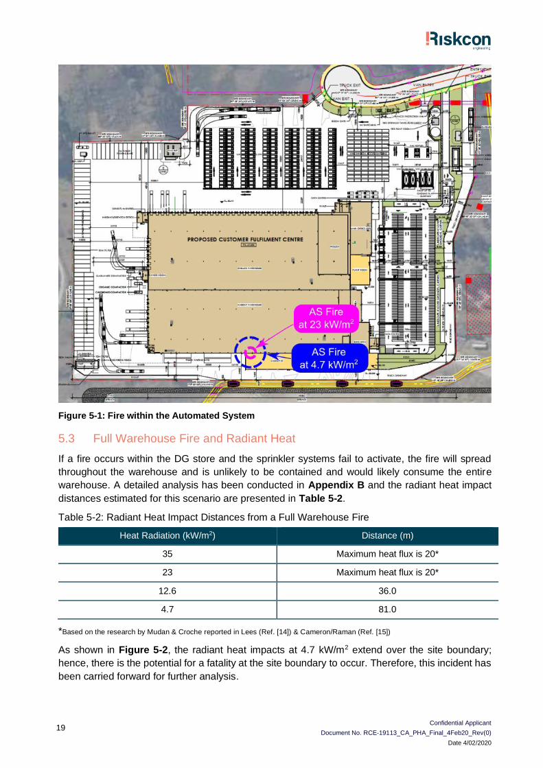
19
Figure 5-1: Fire within the Automated System
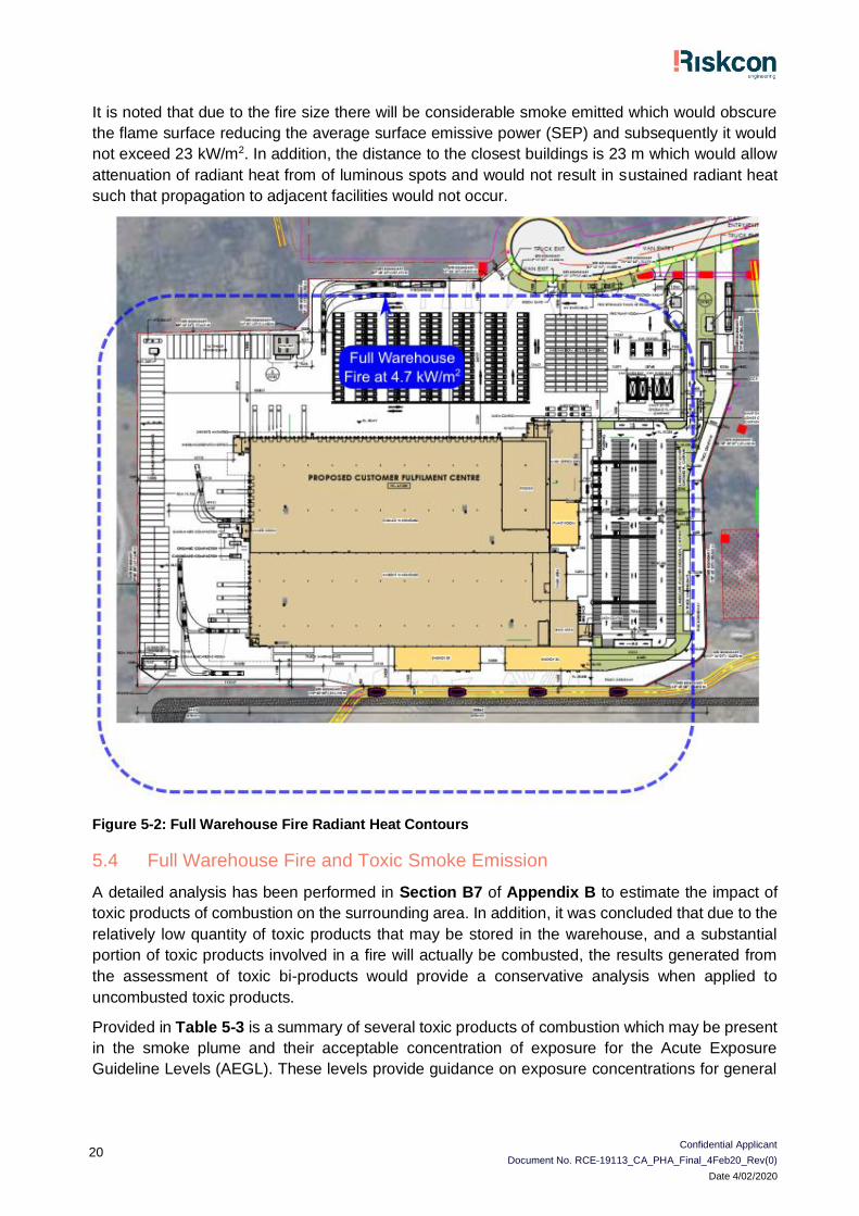
5.3 Full Warehouse Fire and Radiant Heat
If a fire occurs within the DG store and the sprinkler systems fail to activate, the fire will spread
throughout the warehouse and is unlikely to be contained and would likely consume the entire
warehouse. A detailed analysis has been conducted in Appendix B and the radiant heat impact
distances estimated for this scenario are presented in Table 5-2.
Table 5-2: Radiant Heat Impact Distances from a Full Warehouse Fire
Heat Radiation (kW/m2) Distance (m)
35 Maximum heat flux is 20*
23 Maximum heat flux is 20*
12.6 36.0
4.7 81.0
*Based on the research by Mudan & Croche reported in Lees (Ref. [14]) & Cameron/Raman (Ref. [15])
As shown in Figure 5-2, the radiant heat impacts at 4.7 kW/m2 extend over the site boundary;
hence, there is the potential for a fatality at the site boundary to occur. Therefore, this incident has
been carried forward for further analysis.
Confidential Applicant
Document No. RCE-19113_CA_PHA_Final_4Feb20_Rev(0)
Date 4/02/2020
20
It is noted that due to the fire size there will be considerable smoke emitted which would obscure
the flame surface reducing the average surface emissive power (SEP) and subsequently it would
not exceed 23 kW/m2. In addition, the distance to the closest buildings is 23 m which would allow
attenuation of radiant heat from of luminous spots and would not result in sustained radiant heat
such that propagation to adjacent facilities would not occur.
Figure 5-2: Full Warehouse Fire Radiant Heat Contours
5.4 Full Warehouse Fire and Toxic Smoke Emission
A detailed analysis has been performed in Section B7 of Appendix B to estimate the impact of
toxic products of combustion on the surrounding area. In addition, it was concluded that due to the
relatively low quantity of toxic products that may be stored in the warehouse, and a substantial
portion of toxic products involved in a fire will actually be combusted, the results generated from
the assessment of toxic bi-products would provide a conservative analysis when applied to
uncombusted toxic products.
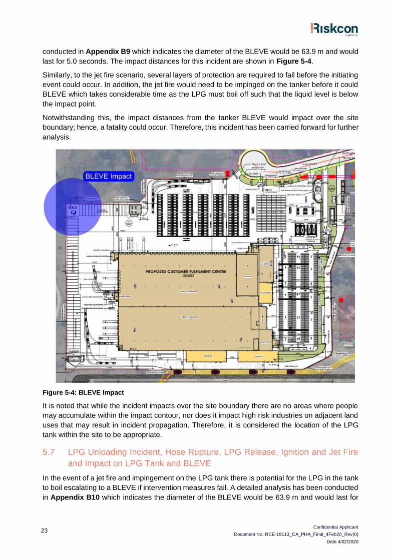
Provided in Table 5-3 is a summary of several toxic products of combustion which may be present
in the smoke plume and their acceptable concentration of exposure for the Acute Exposure
Guideline Levels (AEGL). These levels provide guidance on exposure concentrations for general
Confidential Applicant
Document No. RCE-19113_CA_PHA_Final_4Feb20_Rev(0)
Date 4/02/2020
21
populations, including susceptible populations over a range of exposure times to assist in the
assessment of releases which may result in a toxic exposure.
Provide below is a summary of the AEGL tiers of exposure:
• AEGL-3 is the airborne concentration, expressed as parts per million (ppm) or milligrams per
cubic meter (mg/m3), of a substance above which it is predicted that the general population,
including susceptible individuals, could experience life-threatening health effects or death.
• AEGL-2 is the airborne concentration (expressed as ppm or mg/m3) of a substance above
which it is predicted that the general population, including susceptible individuals, could
experience irreversible or other serious, long-lasting adverse health effects or an impaired
ability to escape.
• AEGL-1 is the airborne concentration (expressed as ppm or mg/m3) of a substance above
which it is predicted that the general population, including susceptible individuals, could
experience notable discomfort, irritation, or certain asymptomatic non-sensory effects.
However, the effects are not disabling and are transient and reversible upon cessation of
exposure.
Selection for fatality or serious injury is based on an AEGL-3 value with injury values selected as
those based on AEGL-2. It is noted the report AEGL values are based on 30-minute exposure.
Table 5-3: Concentrations of Toxic Products of Combustion from a Smoke Plume
Pollutant Fatality or Serious Injury (ppm) Injury (ppm) Concentration (ppm)
Carbon monoxide 600 150 13.1
Nitric Dioxide 25 15 12.2
Hydrogen cyanide 21 10 13.6
Hydrogen chloride 210 43 10.1
Sulphur dioxide 30 0.75 5.7
The analysis indicates all quantities are below the AEGL-3 values. It is noted the analysis
conducted is based on the primary toxic bi-product (carbon monoxide) which forms at rates higher
than other toxic bi-products. Therefore, application of this result to other components is considered
conservative. As these concentrations are taken at the point of release, they will disperse downwind
resulting in substantially lower concentrations at the residential areas.
With reference to injury, all values except for sulphur dioxide are below the AEGL-2 concentration.
Similar to the above discussion, the concentrations are likely to disperse substantially prior to
impacting the residential populations; hence, an injury is unlikely to occur.
Based on the analysis conducted, it is considered that the concentrations at the residential area
are likely to be lower than the fatality and injury concentration levels based on the comparison to
the fatality and injury targets at the point of release. Therefore, it is considered that fatality and
injury are unlikely to occur as a result of this incident. Notwithstanding this, this incident has been
carried forward for conservatism.
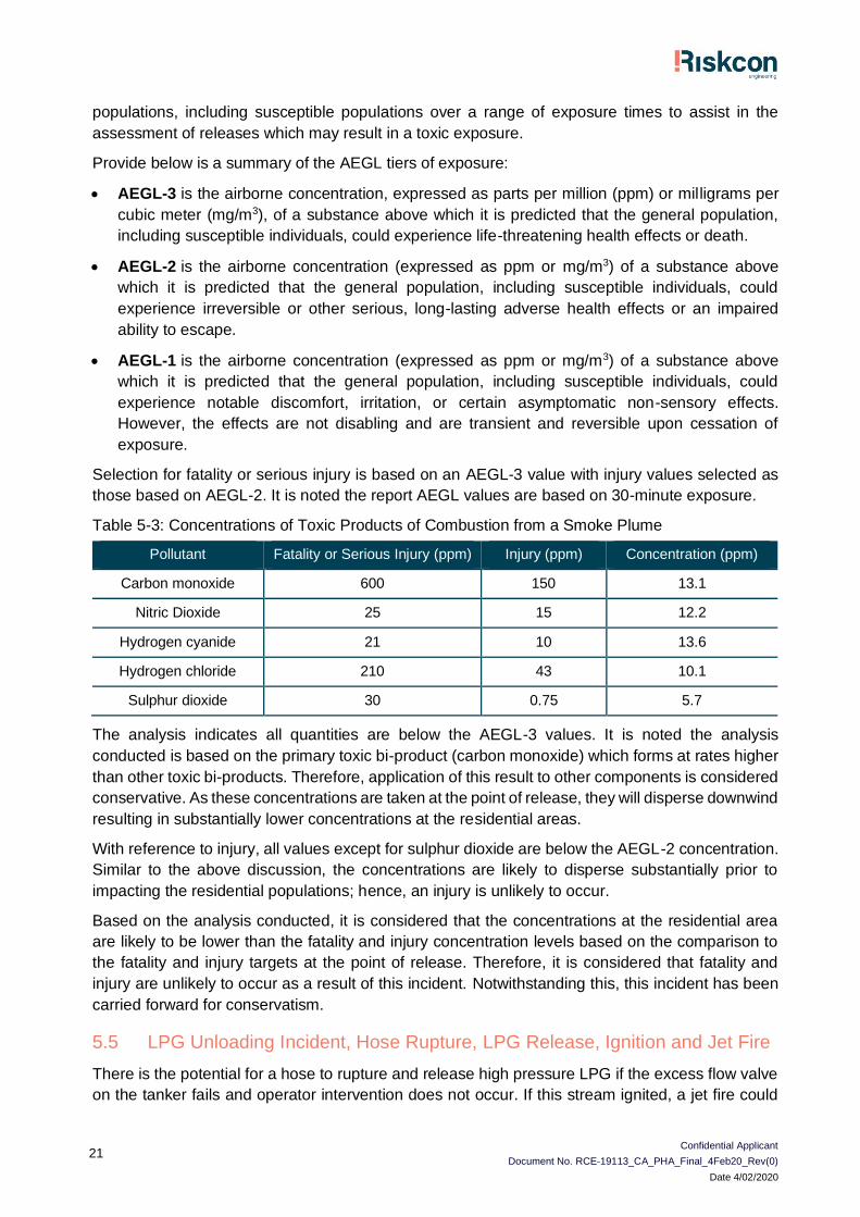
5.5 LPG Unloading Incident, Hose Rupture, LPG Release, Ignition and Jet Fire
There is the potential for a hose to rupture and release high pressure LPG if the excess flow valve
on the tanker fails and operator intervention does not occur. If this stream ignited, a jet fire could
Confidential Applicant
Document No. RCE-19113_CA_PHA_Final_4Feb20_Rev(0)
Date 4/02/2020
22
occur. A detailed analysis has been conducted in Appendix B8 for this scenario which indicates
the jet fire would have an impact of distance of 38 m. The impact distances for this incident are
shown in Figure 5-3.
There are several protection systems to prevent hose rupture including hose pressure testing and
inspections, non-return valves on the tank and vehicle, excess flow valves on the tanker, earthing
connections, ignition source controls. Therefore, it is unlikely that a release of LPG would occur
and subsequent ignition.
Notwithstanding this, the impact distances from the jet fire would impact over the site boundary;
hence, a fatality could occur. Therefore, this incident has been carried forward for further analysis.
Figure 5-3: Impact from a Jet Fire
It is noted that while the incident impacts over the site boundary there are no areas where people
may accumulate within the impact contour, nor does it impact high risk industries on adjacent land
uses that may result in incident propagation. Therefore, it is considered the location of the LPG
tank within the site to be appropriate.
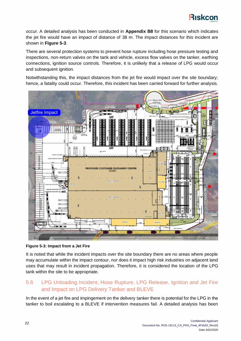
5.6 LPG Unloading Incident, Hose Rupture, LPG Release, Ignition and Jet Fire
and Impact on LPG Delivery Tanker and BLEVE
In the event of a jet fire and impingement on the delivery tanker there is potential for the LPG in the
tanker to boil escalating to a BLEVE if intervention measures fail. A detailed analysis has been
Confidential Applicant
Document No. RCE-19113_CA_PHA_Final_4Feb20_Rev(0)
Date 4/02/2020
23
conducted in Appendix B9 which indicates the diameter of the BLEVE would be 63.9 m and would
last for 5.0 seconds. The impact distances for this incident are shown in Figure 5-4.
Similarly, to the jet fire scenario, several layers of protection are required to fail before the initiating
event could occur. In addition, the jet fire would need to be impinged on the tanker before it could
BLEVE which takes considerable time as the LPG must boil off such that the liquid level is below
the impact point.
Notwithstanding this, the impact distances from the tanker BLEVE would impact over the site
boundary; hence, a fatality could occur. Therefore, this incident has been carried forward for further
analysis.
Figure 5-4: BLEVE Impact
It is noted that while the incident impacts over the site boundary there are no areas where people
may accumulate within the impact contour, nor does it impact high risk industries on adjacent land
uses that may result in incident propagation. Therefore, it is considered the location of the LPG
tank within the site to be appropriate.
5.7 LPG Unloading Incident, Hose Rupture, LPG Release, Ignition and Jet Fire
and Impact on LPG Tank and BLEVE
In the event of a jet fire and impingement on the LPG tank there is potential for the LPG in the tank
to boil escalating to a BLEVE if intervention measures fail. A detailed analysis has been conducted
in Appendix B10 which indicates the diameter of the BLEVE would be 63.9 m and would last for
Confidential Applicant
Document No. RCE-19113_CA_PHA_Final_4Feb20_Rev(0)
Date 4/02/2020
24
5 seconds. The impact distances for this incident are shown in Figure 5-4 as this has the same
fuel profile as the tanker scenario.
The impact distances from the Tank BLEVE would impact over the site boundary; hence, a fatality
could occur. Therefore, this incident has been carried forward for further analysis.
It is noted that while the incident impacts over the site boundary there are no areas where people
may accumulate within the impact contour, nor does it impact high risk industries on adjacent land
uses that may result in incident propagation. Therefore, it is considered the location of the LPG
tank within the site to be appropriate.
Confidential Applicant
Document No. RCE-19113_CA_PHA_Final_4Feb20_Rev(0)
Date 4/02/2020
25
6.0 Frequency Analysis
6.1 Incidents Carried Forward for Frequency Analysis
The following item has been carried forwards for frequency analysis;
• Full warehouse fire and radiant heat.
• Full warehouse fire and toxic smoke emission.
• LPG unloading incident, hose rupture, LPG release, ignition and jet fire.
• LPG unloading incident, hose rupture, LPG release, ignition and jet fire and impact on LPG
delivery tanker and Boiling Liquid Expanding Vapour Explosion (BLEVE).
• LPG unloading incident, hose rupture, LPG release, ignition and jet fire and impact on LPG tank
and BLEVE.
This incident has been assessed in the following section.
6.2 Probability of Failure on Demand
The failure rates for each component identified in the safety systems which protect against the
scenarios in the following sections were sourced from 3rd party databases such as; OREDA, Exida,
UK Health and Safety Executive (HSE). A summary of the failure rate information has been
conducted in Appendix C. Also included in this appendix are the calculations for the probability of
failure on demand (PFD) for each component which is estimated using Equation 7-1.
𝑃𝐹𝐷 =1
2𝜆𝑑𝑢𝑡
Equation 7-1
Where:
• du = dangerous undetected failures of a component
• t = 1/number of test intervals per annum
6.3 Full Warehouse Fire Frequency and Risk Assessment
The frequency of a full warehouse fire at the site can be estimated from a number of sources (e.g.
general warehouse fire frequencies or the summation of individual fire frequencies for each of the
initiating fire events). As this is a preliminary hazard analysis, the fire frequency has been selected
from general fire frequency data.
A detailed fire frequency analysis has been conducted in Appendix C. The results of this analysis
indicate that an initiating fire frequency would be in the order of 1x10⁻³ p.a.
It is noted that the site is fitted with multiple automatic sprinkler systems that will initiate on fire
detection, controlling the fire and preventing the fire growth to a full warehouse fire. The Centre for
Chemical Process Safety (CCPS) provides failure rate data for water fire protection systems
including all components (pump, distribution system, nozzles, seals, piping, controls and base
plate) of 9.66 per 106 hours (Ref. [16]). The hourly failure rate is converted to failures per annum
by:
Failures per Annum = Failures per hour x 8760 hours per year
Failures per Annum = 9.66x106 x 8760 = 0.085
Confidential Applicant
Document No. RCE-19113_CA_PHA_Final_4Feb20_Rev(0)
Date 4/02/2020
26
The system will only operate when a fire is detected; hence, the system operates in demand mode.
The protection system will be tested monthly totalling 12 tests per annum. The probability of failure
on demand (PFD) is estimated using:
𝑃𝐹𝐷 =1
2𝜆𝑑𝑢 (
1
𝑡)
Where:
du = dangerous undetected failures of a component
t = 1/number of test intervals per annum
PFD = 0.5 (0.085) (1/12) = 0.00353
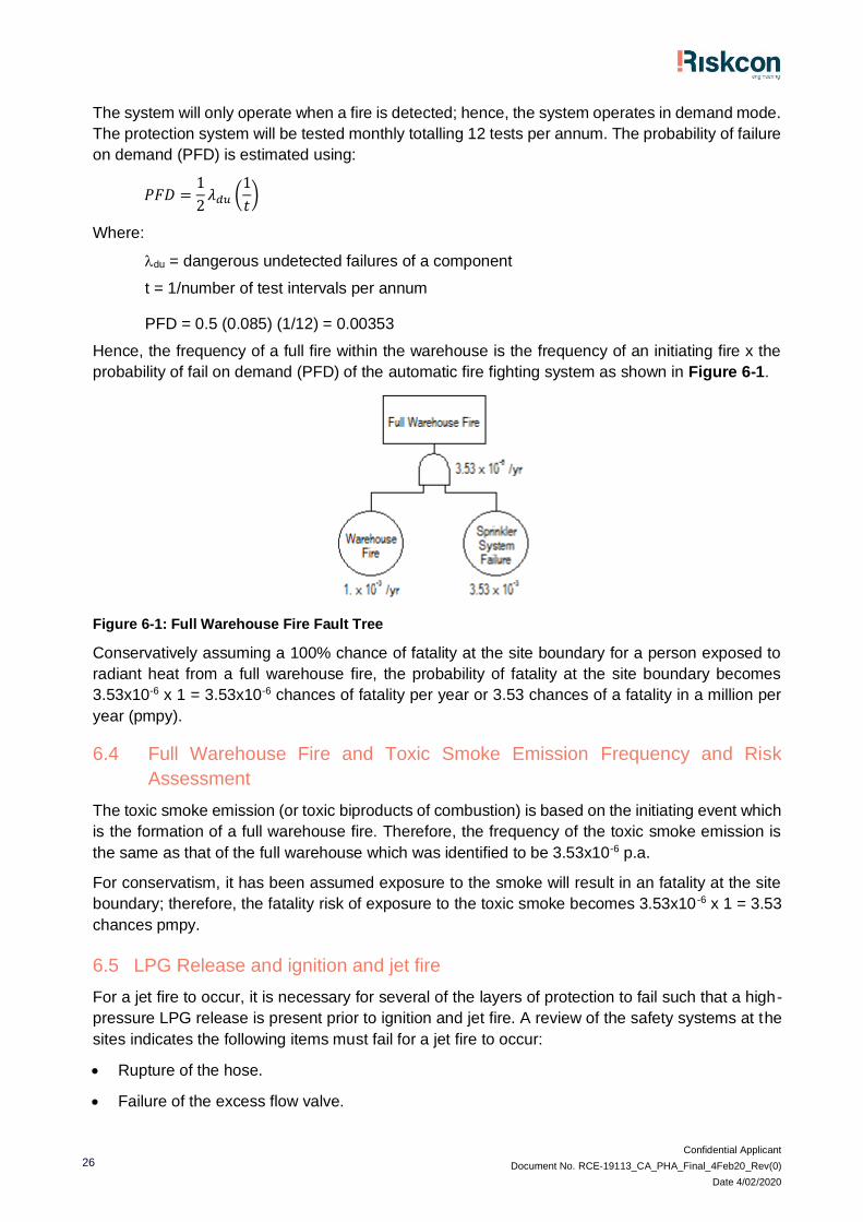
Hence, the frequency of a full fire within the warehouse is the frequency of an initiating fire x the
probability of fail on demand (PFD) of the automatic fire fighting system as shown in Figure 6-1.
Figure 6-1: Full Warehouse Fire Fault Tree
Conservatively assuming a 100% chance of fatality at the site boundary for a person exposed to
radiant heat from a full warehouse fire, the probability of fatality at the site boundary becomes
3.53x10-6 x 1 = 3.53x10⁻⁶ chances of fatality per year or 3.53 chances of a fatality in a million per
year (pmpy).
6.4 Full Warehouse Fire and Toxic Smoke Emission Frequency and Risk
Assessment
The toxic smoke emission (or toxic biproducts of combustion) is based on the initiating event which
is the formation of a full warehouse fire. Therefore, the frequency of the toxic smoke emission is
the same as that of the full warehouse which was identified to be 3.53x10⁻⁶ p.a.
For conservatism, it has been assumed exposure to the smoke will result in an fatality at the site
boundary; therefore, the fatality risk of exposure to the toxic smoke becomes 3.53x10 -6 x 1 = 3.53
chances pmpy.
6.5 LPG Release and ignition and jet fire
For a jet fire to occur, it is necessary for several of the layers of protection to fail such that a high-
pressure LPG release is present prior to ignition and jet fire. A review of the safety systems at the
sites indicates the following items must fail for a jet fire to occur:
• Rupture of the hose.
• Failure of the excess flow valve.

Confidential Applicant
Document No. RCE-19113_CA_PHA_Final_4Feb20_Rev(0)
Date 4/02/2020
27
• Failure of the non-return valve.
• Failure of the emergency stop button to activate the isolation valves.
• Failure of the isolation valves.
Failure rate information for each component has been taken from Appendix C and is summarised
in Table 6-1.
Table 6-1: Failure Rate Data
Component PFD
Hose 1.04x10⁻⁵ (Frequency)
Excess flow valve 6.5x10⁻³
Non-return valve 6.5x10⁻³
Emergency Stop 2.71x10⁻⁵
Isolation Valves 5x10⁻³
In addition to the components of the safety system to fail, it is necessary for the operator to fail to
initiate an emergency stop and the release needs to ignite. HEART human error probabilities (Ref.
[17]) and Human Factors in QRA (Ref. [18]) provide failure rates of operators for tasks similar to
that required by an operator to initiate an emergency stop. These are;
• Routine, highly-practised, rapid task involving relatively low level of skill – 0.02;
• Restore or shift a system to original or new state following procedures, with some checking –
0.003; and
• A more complex task, less time variable, some care necessary – 0.01.
Based on a review of these documents a value toward the more conservative end of 0.01 has been
selected for use in this assessment.
Ignition probabilities were sourced from Lees - Loss Prevention in the Process Industries (Ref. [14])
which provides ignition probabilities based on the number of ignition sources at the site. The site
contains very few ignition sources; hence, from Lees, a conservative probability of ignition is
estimated as 0.2.
The PFD for each piece of equipment, operation failure and ignition were input into a fault tree to
determine the overall probability of a failure resulting in a jet fire. The fault tree is shown in Figure
6-2. The analysis indicates a jet fire will occur with a frequency of 4.04x10 -10 chances per annum
(p.a.). The very low frequency indicates that there are many layers of protection at the site,
minimising the potential for incident.
It is noted that for conservatism, the automatic Isolation provided by the plastic air lines, operating
the Isolation valves at the site, have not been included in this assessment. This would provide
further reduction to the already low incident frequency.
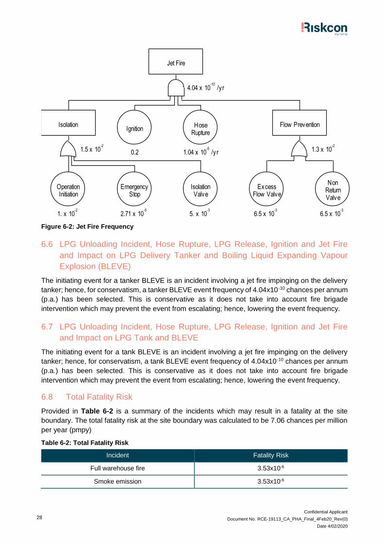
Confidential Applicant
Document No. RCE-19113_CA_PHA_Final_4Feb20_Rev(0)
Date 4/02/2020
28
Figure 6-2: Jet Fire Frequency
6.6 LPG Unloading Incident, Hose Rupture, LPG Release, Ignition and Jet Fire
and Impact on LPG Delivery Tanker and Boiling Liquid Expanding Vapour
Explosion (BLEVE)
The initiating event for a tanker BLEVE is an incident involving a jet fire impinging on the delivery
tanker; hence, for conservatism, a tanker BLEVE event frequency of 4.04x10 -10 chances per annum
(p.a.) has been selected. This is conservative as it does not take into account fire brigade
intervention which may prevent the event from escalating; hence, lowering the event frequency.
6.7 LPG Unloading Incident, Hose Rupture, LPG Release, Ignition and Jet Fire
and Impact on LPG Tank and BLEVE
The initiating event for a tank BLEVE is an incident involving a jet fire impinging on the delivery
tanker; hence, for conservatism, a tank BLEVE event frequency of 4.04x10⁻¹⁰ chances per annum
(p.a.) has been selected. This is conservative as it does not take into account fire brigade
intervention which may prevent the event from escalating; hence, lowering the event frequency.
6.8 Total Fatality Risk
Provided in Table 6-2 is a summary of the incidents which may result in a fatality at the site
boundary. The total fatality risk at the site boundary was calculated to be 7.06 chances per million
per year (pmpy)
Table 6-2: Total Fatality Risk
Incident Fatality Risk
Full warehouse fire 3.53x10⁻⁶
Smoke emission 3.53x10⁻⁶
Jet Fire
4.04 x 10 /yr-10
Isolation
1.5 x 10 -2
InitiationOperation
1. x 10 -2
StopEmergency
2.71 x 10 -5
ValveIsolation
5. x 10 -3
Ignition
0.2
RuptureHose
1.04 x 10 /yr-5
Flow Prevention
1.3 x 10 -2
Flow ValveExcess
6.5 x 10 -3
ValveReturnNon
6.5 x 10 -3
Untitled

Confidential Applicant
Document No. RCE-19113_CA_PHA_Final_4Feb20_Rev(0)
Date 4/02/2020
29
Incident Fatality Risk
Jet fire 4.04x10⁻¹⁰
Tanker BLEVE 4.04x10⁻¹⁰
Tank BLEVE 4.04x10⁻¹⁰
Total 7.06x10⁻⁶
6.9 Comparison Against Risk Criteria
The NSW Department of Planning and Environment has issued a guideline on the acceptable risk
criteria (Ref. [2]). The acceptable risk criteria published in the guideline relates to injury, fatality and
property damage. The values in the guideline present the maximum levels of risk that are
permissible at the land use under assessment. The adjacent land use would be classified as an
industrial site as it is restricted access and only industrial operations are permitted to occur in this
area. For industrial facilities, the maximum permissible fatality risk is 50 pmpy. The assessed
highest fatality risk is 7.06 pmpy at the closest site boundary (eastern boundary); hence, the highest
risk is within the permissible criteria and therefore all other risk points beyond the boundary would
be within the acceptable criteria.
Based on the estimated injury risk, conducted in the analysis above, the risks associated with injury
and nuisances at the closest residential area are not considered to be exceeded.
6.10 Cumulative Assessment
A review of the surrounding area indicates this would be the first development to occur at the estate.
It is proposed to develop an adjacent warehouse which will not store any DGs. Due to the low level
of development and the proposal of the adjacent uses, cumulative risks are not considered to be a
risk at this stage.
6.11 Cumulative Assessment
A review of the surrounding area indicates this would be the first development to occur at the estate.
It is proposed to develop an adjacent warehouse which will not store any DGs. Due to the low level
of development and the proposal of the adjacent uses, cumulative risks are not considered to be a
risk at this stage.
Confidential Applicant
Document No. RCE-19113_CA_PHA_Final_4Feb20_Rev(0)
Date 4/02/2020
30
7.0 Conclusion and Recommendations
7.1 Conclusions
A hazard identification table was developed for warehouse facility to identify potential hazards that
may be present at the site as a result of operations or storage of materials. Based on the identified
hazards, scenarios were postulated that may result in an incident with a potential for offsite impacts.
Postulated scenarios were discussed qualitatively and any scenarios that would not impact offsite
were eliminated from further assessment. Scenarios not eliminated were then carried forward for
consequence analysis.
Incidents carried forward for consequence analysis were assessed in detail to estimate the impact
distances. Impact distances were developed into scenario contours and overlaid onto the site
layout diagram to determine if an offsite impact would occur. The consequence analysis showed
that one of the scenarios (full warehouse fire) would impact over the site boundary and into the
adjacent land use; hence, this incident was carried forward for frequency analysis and risk
assessment.
The frequency analysis and risk assessment showed that the full warehouse fire would have a
fatality risk of 7.06 chances per million per year (pmpy) at the site boundary, with lesser risk at
further distances from the boundary. HIPAP No. 4 (Ref. [2]) publishes acceptable risk criteria at the
site boundary of 50 pmpy (for industrial sites). Therefore, the probability of a fatality from a full
warehouse fire at the site boundary is within the acceptable risk criteria.
In addition, the only incident which may result in impacts to adjacent structures was a full
warehouse fire. Due to the fire size there will be considerable smoke emitted which would obscure
the flame surface reducing the average surface emissive power (SEP) and subsequently it would
not exceed 23 kW/m2. In addition, the distance to the closest buildings is 23 m which would allow
attenuation of radiant heat from of luminous spots and would not result in sustained radiant heat
such that propagation to adjacent facilities would occur.
Review of the estate proposal indicates this development is the only contributor to the risk profile;
hence, cumulative risk is not a consideration at this stage. The cumulative risk at the site is
therefore the reported 7.06 chances pmpy which is below the 50 chances pmpy limit. Therefore,
the development of the warehouse does not increase the cumulative risk of the estate to an
unacceptable level.
Based on the analysis conducted, it is concluded that the risks at the site boundary are not
considered to exceed the acceptable risk criteria; hence, the facility would only be classified as
potentially hazardous and would be permitted within the current land zoning for the site.
7.2 Recommendations
Notwithstanding the conclusions following the analysis of the facility, the following
recommendations have been made:
5. The site shall be designed to contain any spills or contaminated water from a fire incident within
the boundaries of the site.
6. The warehouse and/or site boundaries shall be capable of containing 612 m3 which may be
contained within the warehouse footprint, site stormwater pipework and any recessed docks
or other containment areas that may be present as part of the site design.
Confidential Applicant
Document No. RCE-19113_CA_PHA_Final_4Feb20_Rev(0)
Date 4/02/2020
31
7. The civil engineers designing the site containment shall demonstrate the design is capable of
containing at least 612 m3.
8. A storm water isolation point (i.e. penstock isolation valve) shall be incorporated into the
design. The penstock shall automatically isolate the storm water system upon detection of a
fire (smoke or sprinkler activation) to prevent potentially contaminated liquids from entering the
water course.
Confidential Applicant
Document No. RCE-19113_CA_PHA_Final_4Feb20_Rev(0)
Date 4/02/2020
32
8.0 References
[1] NSW Department of Planning and Environment, “Applying SEPP33 – Hazardous and
Offensive Developments,” NSW Department of Planning and Environment, Sydney, 2011.
[2] Department of Planning, “Hazardous Industry Planning Advisory Paper No. 4 - Risk Criteria
for Land Use Safety Planning,” Department of Planning, Sydney, 2011.
[3] Department of Planning, “Hazardous Industry Planning Advisory Paper No. 6 - Guidelines for
Hazard Analysis,” Department of Planning, Sydney, 2011.
[4] SafeWork NSW, “Work Health and Safety Regulation,” SafeWork NSW, Lisarow, 2017.
[5] Department of Planning, Multi-Level Risk Assessment, Sydney: Department of Planning,
2011.
[6] National Transport Commission (NTC), “Australian Code for the Transport of Dangerous
Goods by Road & Rail, 7th Edition,” 2011.
[7] Standards Australia, AS/NZS 60079.10.1:2009 - Explosive Atmospheres Part 10.1:
Classification of Areas, Explosive Gas Atmospheres, Sydney: Standards Association of
Australia, 2009.
[8] Road Safety Council, The Australian Code for the Transport of Dangerous Goods by Road
and Rail Edition 7.4, Canberra: Road Safety Council, 2016.
[9] Standards Australia, AS/NZS 1596:2014 - The Storage and Handling of LP Gas, Sydney:
Standards Australia, 2014.
[10] Standards Australia, “AS 1210:2010 - Pressure Vessels,” Standards Australia, Sydney, 2010.
[11] Standards Australia, “AS/NZS 3833:2007 - Storage and Handling of Mixed Classes of
Dangerous Goods, in Packages and Intermediate Bulk Containers,” Standards Australia,
Sydney, 2007.
[12] NSW Department of Planning, “Best Practice Guidelines for Contaminated Water Retention
and Treatment Systems,” NSW Department of Planning, Sydney, 1994.
[13] Standards Australia, AS 1940-2017 - Storage and Handling of Flammable and Combustible
Liquids, Sydney: Standards Australia, 2017.
[14] F. P. Lees, Loss Prevention in the Process Industries, London: Butterworth-Heinemann, 2005.
[15] I. Cameron and R. Raman, Process Systems Risk Management, San Diego: Elsevier, 2005.
[16] Centre for Chemical Process Safety, “Guidelines for Process Equipment Reliability Data with
Data Tables,” Centre for Chemical Process Safety, 1989.

Confidential Applicant
Document No. RCE-19113_CA_PHA_Final_4Feb20_Rev(0)
Date 4/02/2020
33
[17] Health and Safety Executive, Health Failure Rate and Event Data for use within Risk
Assessments, United Kingdom: Health and Safety Executive, 2012.
[18] J. C. Williams, A Data Based Method for Assessing and Reducing Human Error, Proceedings
of IEEE 4th Conference on Human Factors in Power Plants, Monteray, California, 1988.
[19] Standards Australia, AS/NZS 60079.14:2009 - Explosive Atmospheres Part 14: Electrical
Installations, Design, Selection and Erection, Sydney: Standards Australia, 2009.
[20] Standards Australia, “AS 1692-2006 - Steel tanks for flammable and combustible liquids,”
Standards Australia, Sydney, 2006.
[21] I. R. R. Cameron, Process Systems Risk Management, Sydney: Elsevier Academic Press,
2005.
[22] Thermal-Fluids Central, “Heat of Combustion,” Global Digital Central, 8 July 2011. [Online].
Available:
https://www.thermalfluidscentral.org/encyclopedia/index.php/Heat_of_Combustion.
[Accessed 4 July 2017].
Confidential Applicant
Document No. RCE-19113_CA_PHA_Final_4Feb20_Rev(0)
Date 4/02/2020
34
Appendix A
Hazard Identification Table
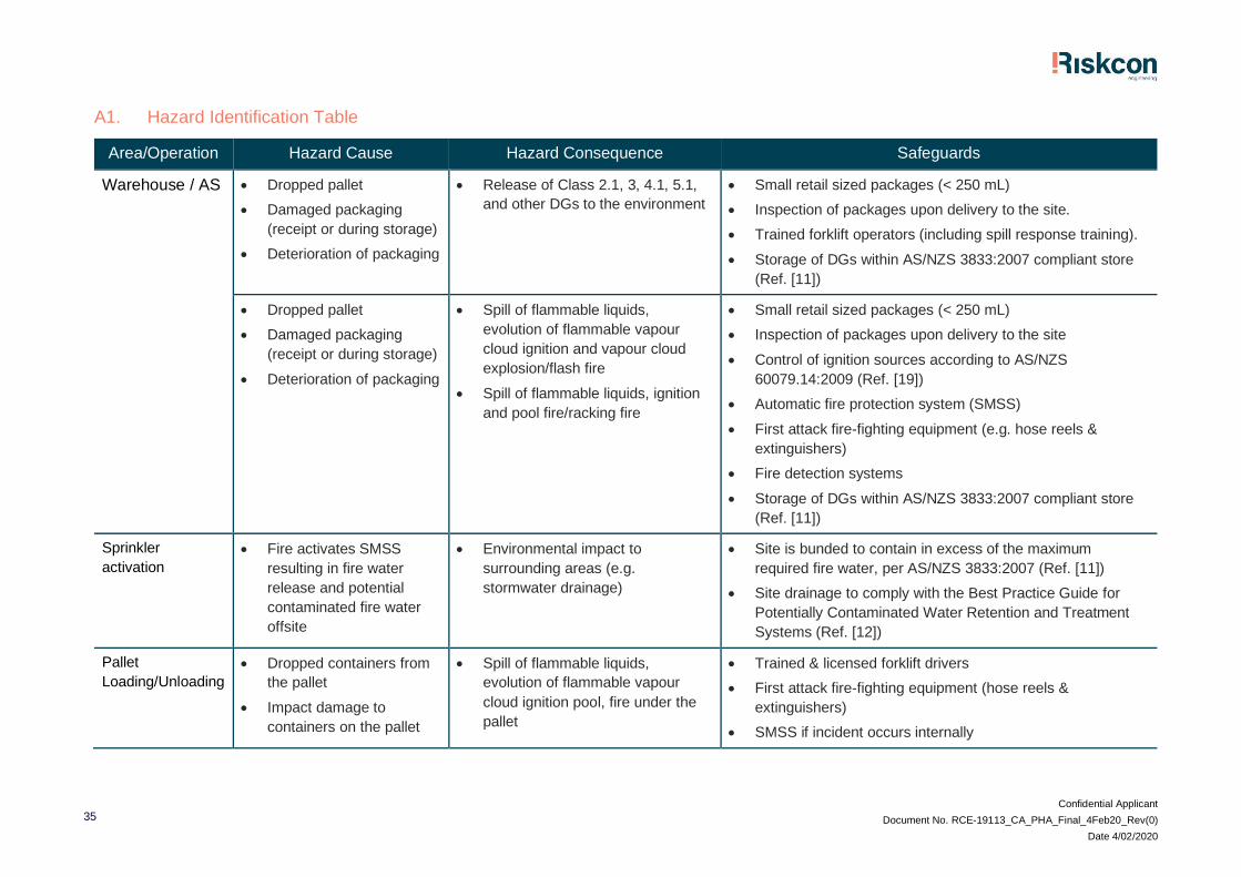
Confidential Applicant
Document No. RCE-19113_CA_PHA_Final_4Feb20_Rev(0)
Date 4/02/2020
35
A1. Hazard Identification Table
Area/Operation Hazard Cause Hazard Consequence Safeguards
Warehouse / AS • Dropped pallet
• Damaged packaging
(receipt or during storage)
• Deterioration of packaging
• Release of Class 2.1, 3, 4.1, 5.1,
and other DGs to the environment
• Small retail sized packages (< 250 mL)
• Inspection of packages upon delivery to the site.
• Trained forklift operators (including spill response training).
• Storage of DGs within AS/NZS 3833:2007 compliant store
(Ref. [11])
• Dropped pallet
• Damaged packaging
(receipt or during storage)
• Deterioration of packaging
• Spill of flammable liquids,
evolution of flammable vapour
cloud ignition and vapour cloud
explosion/flash fire
• Spill of flammable liquids, ignition
and pool fire/racking fire
• Small retail sized packages (< 250 mL)
• Inspection of packages upon delivery to the site
• Control of ignition sources according to AS/NZS
60079.14:2009 (Ref. [19])
• Automatic fire protection system (SMSS)
• First attack fire-fighting equipment (e.g. hose reels &
extinguishers)
• Fire detection systems
• Storage of DGs within AS/NZS 3833:2007 compliant store
(Ref. [11])
Sprinkler
activation
• Fire activates SMSS
resulting in fire water
release and potential
contaminated fire water
offsite
• Environmental impact to
surrounding areas (e.g.
stormwater drainage)
• Site is bunded to contain in excess of the maximum
required fire water, per AS/NZS 3833:2007 (Ref. [11])
• Site drainage to comply with the Best Practice Guide for
Potentially Contaminated Water Retention and Treatment
Systems (Ref. [12])
Pallet
Loading/Unloading
• Dropped containers from
the pallet
• Impact damage to
containers on the pallet
• Spill of flammable liquids,
evolution of flammable vapour
cloud ignition pool, fire under the
pallet
• Trained & licensed forklift drivers
• First attack fire-fighting equipment (hose reels &
extinguishers)
• SMSS if incident occurs internally
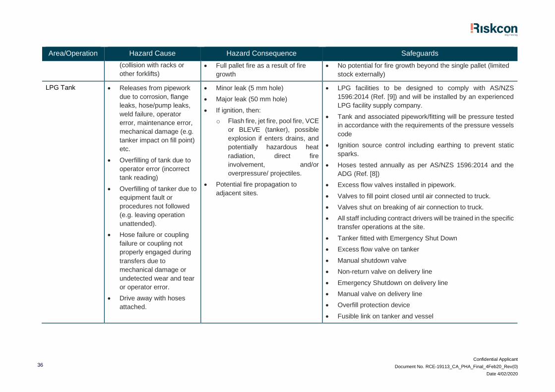
Confidential Applicant
Document No. RCE-19113_CA_PHA_Final_4Feb20_Rev(0)
Date 4/02/2020
36
Area/Operation Hazard Cause Hazard Consequence Safeguards
(collision with racks or
other forklifts)
• Full pallet fire as a result of fire
growth
• No potential for fire growth beyond the single pallet (limited
stock externally)
LPG Tank • Releases from pipework
due to corrosion, flange
leaks, hose/pump leaks,
weld failure, operator
error, maintenance error,
mechanical damage (e.g.
tanker impact on fill point)
etc.
• Overfilling of tank due to
operator error (incorrect
tank reading)
• Overfilling of tanker due to
equipment fault or
procedures not followed
(e.g. leaving operation
unattended).
• Hose failure or coupling
failure or coupling not
properly engaged during
transfers due to
mechanical damage or
undetected wear and tear
or operator error.
• Drive away with hoses
attached.
• Minor leak (5 mm hole)
• Major leak (50 mm hole)
• If ignition, then:
o Flash fire, jet fire, pool fire, VCE
or BLEVE (tanker), possible
explosion if enters drains, and
potentially hazardous heat
radiation, direct fire
involvement, and/or
overpressure/ projectiles.
• Potential fire propagation to
adjacent sites.
• LPG facilities to be designed to comply with AS/NZS
1596:2014 (Ref. [9]) and will be installed by an experienced
LPG facility supply company.
• Tank and associated pipework/fitting will be pressure tested
in accordance with the requirements of the pressure vessels
code
• Ignition source control including earthing to prevent static
sparks.
• Hoses tested annually as per AS/NZS 1596:2014 and the
ADG (Ref. [8])
• Excess flow valves installed in pipework.
• Valves to fill point closed until air connected to truck.
• Valves shut on breaking of air connection to truck.
• All staff including contract drivers will be trained in the specific
transfer operations at the site.
• Tanker fitted with Emergency Shut Down
• Excess flow valve on tanker
• Manual shutdown valve
• Non-return valve on delivery line
• Emergency Shutdown on delivery line
• Manual valve on delivery line
• Overfill protection device
• Fusible link on tanker and vessel
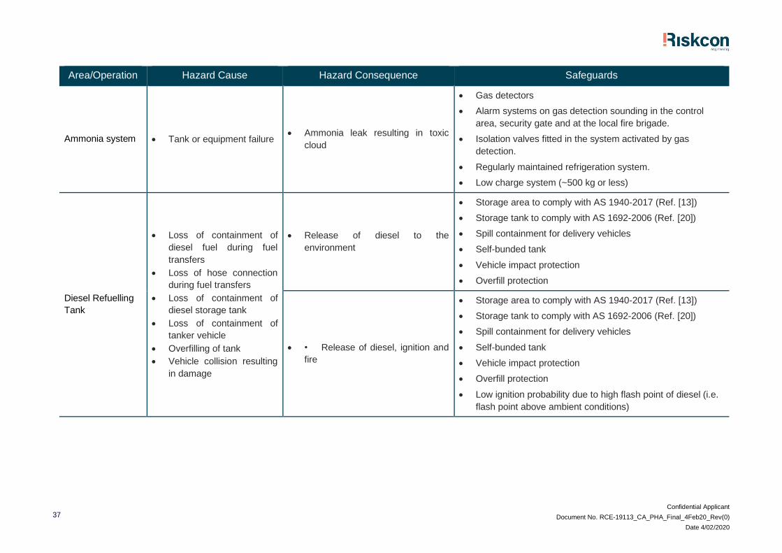
Confidential Applicant
Document No. RCE-19113_CA_PHA_Final_4Feb20_Rev(0)
Date 4/02/2020
37
Area/Operation Hazard Cause Hazard Consequence Safeguards
Ammonia system • Tank or equipment failure • Ammonia leak resulting in toxic
cloud
• Gas detectors
• Alarm systems on gas detection sounding in the control
area, security gate and at the local fire brigade.
• Isolation valves fitted in the system activated by gas
detection.
• Regularly maintained refrigeration system.
• Low charge system (~500 kg or less)
Diesel Refuelling
Tank
• Loss of containment of
diesel fuel during fuel
transfers
• Loss of hose connection
during fuel transfers
• Loss of containment of
diesel storage tank
• Loss of containment of
tanker vehicle
• Overfilling of tank
• Vehicle collision resulting
in damage
• Release of diesel to the
environment
• Storage area to comply with AS 1940-2017 (Ref. [13])
• Storage tank to comply with AS 1692-2006 (Ref. [20])
• Spill containment for delivery vehicles
• Self-bunded tank
• Vehicle impact protection
• Overfill protection
• • Release of diesel, ignition and
fire
• Storage area to comply with AS 1940-2017 (Ref. [13])
• Storage tank to comply with AS 1692-2006 (Ref. [20])
• Spill containment for delivery vehicles
• Self-bunded tank
• Vehicle impact protection
• Overfill protection
• Low ignition probability due to high flash point of diesel (i.e.
flash point above ambient conditions)
Confidential Applicant
Document No. RCE-19113_CA_PHA_Final_4Feb20_Rev(0)
Date 4/02/2020
38
Appendix B
Consequence Analysis

Confidential Applicant
Document No. RCE-19113_CA_PHA_Final_4Feb20_Rev(0)
Date 4/02/2020
39
B1. Incidents Assessed in Detailed Consequence Analysis
The following incidents are assessed for consequence impacts.
• Fire within the Automated System.
• Full warehouse fire and radiant heat.
• Full warehouse fire and toxic smoke emission.
• LPG unloading incident, hose rupture, LPG release, ignition and jet fire.
• LPG unloading incident, hose rupture, LPG release, ignition and jet fire and impact on LPG
delivery tanker and Boiling Liquid Expanding Vapour Explosion (BLEVE).
• LPG unloading incident, hose rupture, LPG release, ignition and jet fire and impact on LPG tank
and BLEVE.
Each incident has been assessed in the sections below.
B2. Spreadsheet Calculator (SSC)
The SSC is designed on the basis of finite elements. The liquid flame area is calculated as if it is a
circle to find the radius for input into the SSC model.
The SSC is designed on the basis of finite elements. The liquid flame area is calculated as if it is a
circle to find the radius for input into the SSC model. Appendix Figure B-1 shows a typical pool
fire, indicating the target and fire impact details.
Appendix Figure B-1: Heat Radiation on a Target from a Cylindrical Flame
A fire in a bund or at a tank roof will act as a cylinder with the heat from the cylindrical flame radiating
to the surrounding area. A number of mathematical models may be used for estimating the heat
radiation impacts at various distances from the fire. The point source method is adequate for
assessing impacts in the far field; however, a more effective approach is the view factor method,
which uses the flame shape to determine the fraction of heat radiated from the flame to a target.
The radiated heat is also reduced by the presence of water vapour and the amount of carbon
dioxide in air. The formula for estimating the heat radiation impact at a set distance is shown in
Equation B-1 (Ref. [15]).
𝑄 = 𝐸𝐹𝜏 Equation B-1
Where:
• Q = incident heat flux at the receiver (kW/m2)
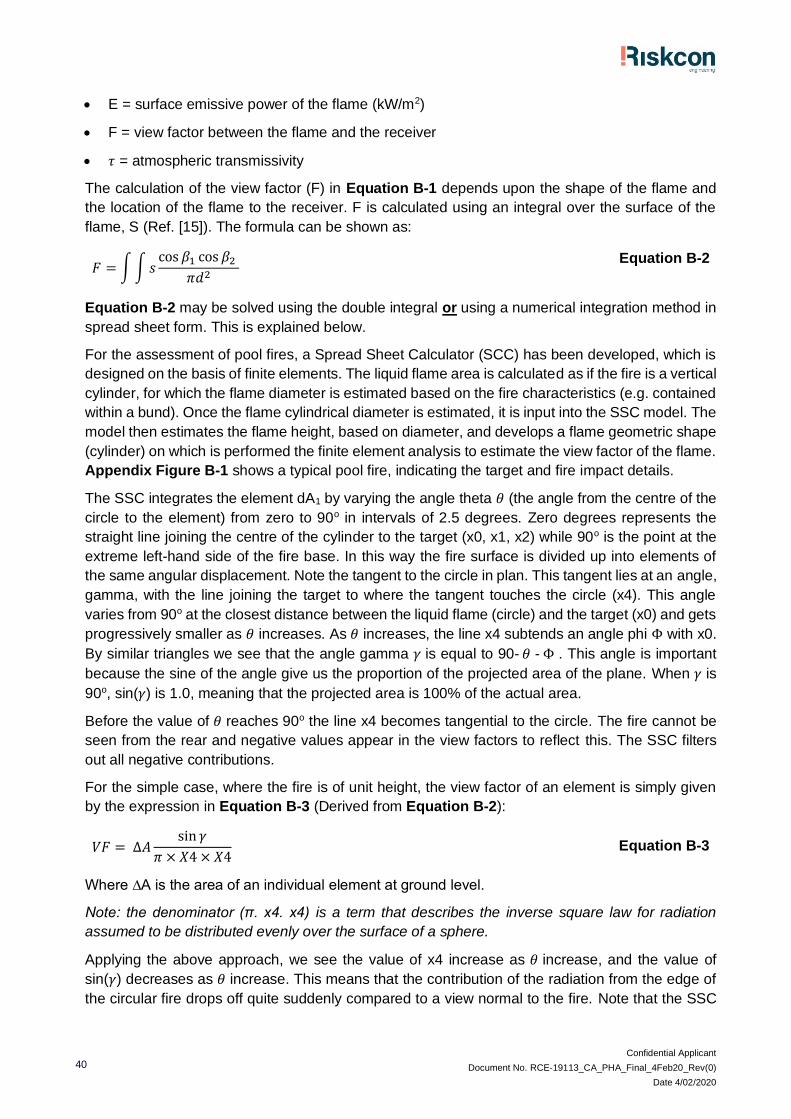
Confidential Applicant
Document No. RCE-19113_CA_PHA_Final_4Feb20_Rev(0)
Date 4/02/2020
40
• E = surface emissive power of the flame (kW/m2)
• F = view factor between the flame and the receiver
• 𝜏 = atmospheric transmissivity
The calculation of the view factor (F) in Equation B-1 depends upon the shape of the flame and
the location of the flame to the receiver. F is calculated using an integral over the surface of the
flame, S (Ref. [15]). The formula can be shown as:
𝐹 = ∫ ∫ 𝑠cos 𝛽1 cos 𝛽2
𝜋𝑑2
Equation B-2
Equation B-2 may be solved using the double integral or using a numerical integration method in
spread sheet form. This is explained below.
For the assessment of pool fires, a Spread Sheet Calculator (SCC) has been developed, which is
designed on the basis of finite elements. The liquid flame area is calculated as if the fire is a vertical
cylinder, for which the flame diameter is estimated based on the fire characteristics (e.g. contained
within a bund). Once the flame cylindrical diameter is estimated, it is input into the SSC model. The
model then estimates the flame height, based on diameter, and develops a flame geometric shape
(cylinder) on which is performed the finite element analysis to estimate the view factor of the flame.
Appendix Figure B-1 shows a typical pool fire, indicating the target and fire impact details.
The SSC integrates the element dA1 by varying the angle theta 𝜃 (the angle from the centre of the
circle to the element) from zero to 90o in intervals of 2.5 degrees. Zero degrees represents the
straight line joining the centre of the cylinder to the target (x0, x1, x2) while 90o is the point at the
extreme left-hand side of the fire base. In this way the fire surface is divided up into elements of
the same angular displacement. Note the tangent to the circle in plan. This tangent lies at an angle,
gamma, with the line joining the target to where the tangent touches the circle (x4). This angle
varies from 90o at the closest distance between the liquid flame (circle) and the target (x0) and gets
progressively smaller as 𝜃 increases. As 𝜃 increases, the line x4 subtends an angle phi Φ with x0.
By similar triangles we see that the angle gamma 𝛾 is equal to 90- 𝜃 - Φ . This angle is important
because the sine of the angle give us the proportion of the projected area of the plane. When 𝛾 is
90o, sin(𝛾) is 1.0, meaning that the projected area is 100% of the actual area.
Before the value of 𝜃 reaches 90o the line x4 becomes tangential to the circle. The fire cannot be
seen from the rear and negative values appear in the view factors to reflect this. The SSC filters
out all negative contributions.
For the simple case, where the fire is of unit height, the view factor of an element is simply given
by the expression in Equation B-3 (Derived from Equation B-2):
𝑉𝐹 = ∆𝐴sin 𝛾
𝜋 × 𝑋4 × 𝑋4 Equation B-3
Where ∆A is the area of an individual element at ground level.
Note: the denominator (π. x4. x4) is a term that describes the inverse square law for radiation
assumed to be distributed evenly over the surface of a sphere.
Applying the above approach, we see the value of x4 increase as 𝜃 increase, and the value of
sin(𝛾) decreases as 𝜃 increase. This means that the contribution of the radiation from the edge of
the circular fire drops off quite suddenly compared to a view normal to the fire. Note that the SSC
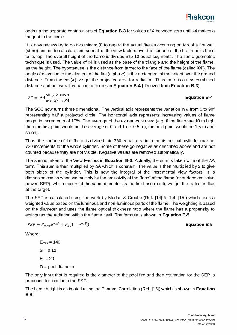
Confidential Applicant
Document No. RCE-19113_CA_PHA_Final_4Feb20_Rev(0)
Date 4/02/2020
41
adds up the separate contributions of Equation B-3 for values of 𝜃 between zero until x4 makes a
tangent to the circle.
It is now necessary to do two things: (i) to regard the actual fire as occurring on top of a fire wall
(store) and (ii) to calculate and sum all of the view factors over the surface of the fire from its base
to its top. The overall height of the flame is divided into 10 equal segments. The same geometric
technique is used. The value of x4 is used as the base of the triangle and the height of the flame,
as the height. The hypotenuse is the distance from target to the face of the flame (called X4’). The
angle of elevation to the element of the fire (alpha 𝛼) is the arctangent of the height over the ground
distance. From the cos(𝛼) we get the projected area for radiation. Thus there is a new combined
distance and an overall equation becomes in Equation B-4 ((Derived from Equation B-3):
𝑉𝐹 = ∆𝐴sin 𝛾 × cos 𝛼
𝜋 × 𝑋4 × 𝑋4 Equation B-4
The SCC now turns three dimensional. The vertical axis represents the variation in 𝜃 from 0 to 90o
representing half a projected circle. The horizontal axis represents increasing values of flame
height in increments of 10%. The average of the extremes is used (e.g. if the fire were 10 m high
then the first point would be the average of 0 and 1 i.e. 0.5 m), the next point would be 1.5 m and
so on).
Thus, the surface of the flame is divided into 360 equal area increments per half cylinder making
720 increments for the whole cylinder. Some of these go negative as described above and are not
counted because they are not visible. Negative values are removed automatically.
The sum is taken of the View Factors in Equation B-3. Actually, the sum is taken without the ∆A
term. This sum is then multiplied by ∆A which is constant. The value is then multiplied by 2 to give
both sides of the cylinder. This is now the integral of the incremental view factors. It is
dimensionless so when we multiply by the emissivity at the “face” of the flame (or surface emissive
power, SEP), which occurs at the same diameter as the fire base (pool), we get the radiation flux
at the target.
The SEP is calculated using the work by Mudan & Croche (Ref. [14] & Ref. [15]) which uses a
weighted value based on the luminous and non-luminous parts of the flame. The weighting is based
on the diameter and uses the flame optical thickness ratio where the flame has a propensity to
extinguish the radiation within the flame itself. The formula is shown in Equation B-5.
𝑆𝐸𝑃 = 𝐸𝑚𝑎𝑥𝑒−𝑠𝐷 + 𝐸𝑠(1 − 𝑒−𝑠𝐷) Equation B-5
Where;
Emax = 140
S = 0.12
Es = 20
D = pool diameter
The only input that is required is the diameter of the pool fire and then estimation for the SEP is
produced for input into the SSC.
The flame height is estimated using the Thomas Correlation (Ref. [15]) which is shown in Equation
B-6.
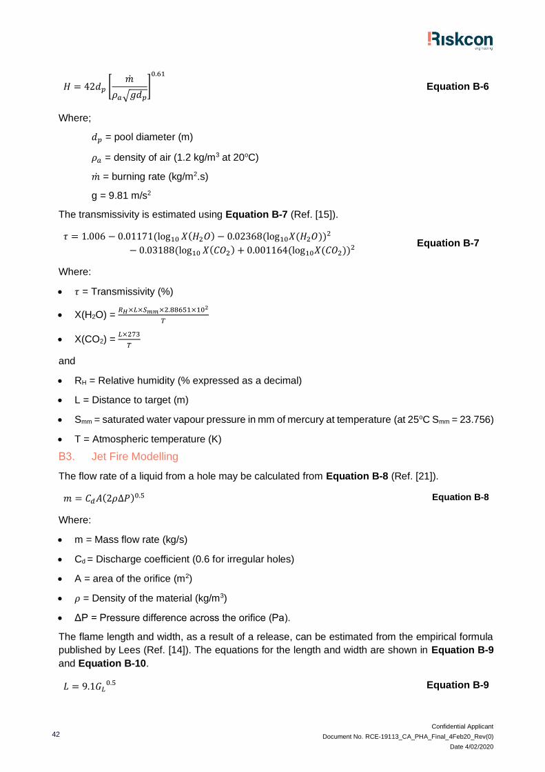
Confidential Applicant
Document No. RCE-19113_CA_PHA_Final_4Feb20_Rev(0)
Date 4/02/2020
42
𝐻 = 42𝑑𝑝 [�̇�
𝜌𝑎√𝑔𝑑𝑝
]
0.61
Equation B-6
Where;
𝑑𝑝 = pool diameter (m)
𝜌𝑎 = density of air (1.2 kg/m3 at 20oC)
�̇� = burning rate (kg/m2.s)
g = 9.81 m/s2
The transmissivity is estimated using Equation B-7 (Ref. [15]).
𝜏 = 1.006 − 0.01171(log10 𝑋(𝐻2𝑂) − 0.02368(log10𝑋(𝐻2𝑂))2
− 0.03188(log10 𝑋(𝐶𝑂2) + 0.001164(log10𝑋(𝐶𝑂2))2 Equation B-7
Where:
• 𝜏 = Transmissivity (%)
• X(H2O) = 𝑅𝐻×𝐿×𝑆𝑚𝑚×2.88651×10²
𝑇
• X(CO2) = 𝐿×273
𝑇
and
• RH = Relative humidity (% expressed as a decimal)
• L = Distance to target (m)
• Smm = saturated water vapour pressure in mm of mercury at temperature (at 25oC Smm = 23.756)
• T = Atmospheric temperature (K)
B3. Jet Fire Modelling
The flow rate of a liquid from a hole may be calculated from Equation B-8 (Ref. [21]).
𝑚 = 𝐶𝑑𝐴(2𝜌∆𝑃)0.5 Equation B-8
Where:
• m = Mass flow rate (kg/s)
• Cd = Discharge coefficient (0.6 for irregular holes)
• A = area of the orifice (m2)
• 𝜌 = Density of the material (kg/m3)
• ΔP = Pressure difference across the orifice (Pa).
The flame length and width, as a result of a release, can be estimated from the empirical formula
published by Lees (Ref. [14]). The equations for the length and width are shown in Equation B-9
and Equation B-10.
𝐿 = 9.1𝐺𝐿0.5 Equation B-9
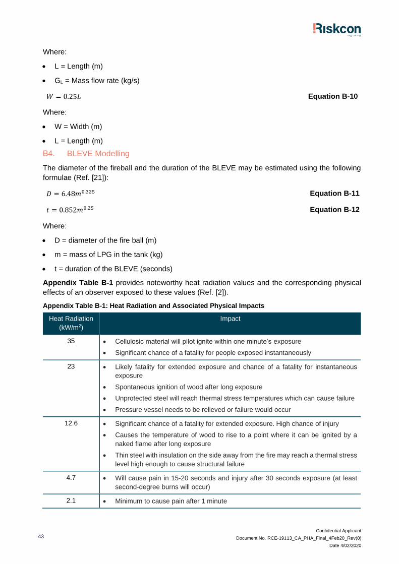
Confidential Applicant
Document No. RCE-19113_CA_PHA_Final_4Feb20_Rev(0)
Date 4/02/2020
43
Where:
• L = Length (m)
• GL = Mass flow rate (kg/s)
𝑊 = 0.25𝐿 Equation B-10
Where:
• W = Width (m)
• L = Length (m)
B4. BLEVE Modelling
The diameter of the fireball and the duration of the BLEVE may be estimated using the following
formulae (Ref. [21]):
𝐷 = 6.48𝑚0.325 Equation B-11
𝑡 = 0.852𝑚0.25 Equation B-12
Where:
• D = diameter of the fire ball (m)
• m = mass of LPG in the tank (kg)
• t = duration of the BLEVE (seconds)
Appendix Table B-1 provides noteworthy heat radiation values and the corresponding physical
effects of an observer exposed to these values (Ref. [2]).
Appendix Table B-1: Heat Radiation and Associated Physical Impacts
Heat Radiation
(kW/m2)
Impact
35 • Cellulosic material will pilot ignite within one minute’s exposure
• Significant chance of a fatality for people exposed instantaneously
23 • Likely fatality for extended exposure and chance of a fatality for instantaneous
exposure
• Spontaneous ignition of wood after long exposure
• Unprotected steel will reach thermal stress temperatures which can cause failure
• Pressure vessel needs to be relieved or failure would occur
12.6 • Significant chance of a fatality for extended exposure. High chance of injury
• Causes the temperature of wood to rise to a point where it can be ignited by a
naked flame after long exposure
• Thin steel with insulation on the side away from the fire may reach a thermal stress
level high enough to cause structural failure
4.7 • Will cause pain in 15-20 seconds and injury after 30 seconds exposure (at least
second-degree burns will occur)
2.1 • Minimum to cause pain after 1 minute

Confidential Applicant
Document No. RCE-19113_CA_PHA_Final_4Feb20_Rev(0)
Date 4/02/2020
44
B5. Fire Within Automated System
In the event that a flammable liquid package or aerosol is damaged and flammable materials are
released the volatile component will vaporise which may contact an ignition source resulting in a
pool fire. As the fire grows it may accelerate the deterioration of other packages resulting in failure
and release of additional flammable material and combustion of packaging.
As heat and smoke is generated from the fire the SMSS will activate. Two sprinkler activation
scenarios have been assessed:
• A worst credible (WC) scenario whereby the first row of the SMSS activates and controls the
spread of a fire.
• A sensitivity scenario whereby the first row of sprinklers fails to activate, and the fire is instead
controlled by the second row of the SMSS.
The first row of sprinklers has an approximate diameter of 3 m with the second row having an
approximate diameter of 9 m. These diameters are used to estimate the flame height and SEP for
the fire scenarios. To estimate the flame height and SEP the following information was substituted
into the models:
• Equivalent fire diameter: WC – 3 m, Sensitivity - 9 m
• Burning rate – 0.0667 kg/m2.s (this value encompasses a large range of flammable liquid
burning rates and is considered conservative due to the nature of the flammable liquids stored,
Ref. [14])
The selection of a flammable liquid burning rate is considered appropriate and conservative as the
fire will be composed of burning flammable liquids and packaging. The packaging is a solid material
that will yield a lower burning rate than selected as it requires an additional phase change prior to
combustion reducing the rate at which the product burns.
Furthermore, the analysis is considered incredibly conservative as it assumes a 100% burning
area; however, as the subject areas will encompass aisle spaces, which will have no combustible
material stored these locations. Therefore, it is considered the results generated from this analysis
would substantially overestimate the radiant heat impacts from the identified scenarios.
The results for flame height and SEP for each scenario are summarised in Appendix Table B-2.
Appendix Table B-2: Flame Height and SEP for a Flammable Material Sprinkler Controlled Fire
Output Base Case Sensitivity
Flame Height (m) 7.7 16.5
SEP (kW/m2) 103.7 60.8
The inputs summarised in Appendix Table B-2 were input in to the SSC with the results for each
scenario shown in Appendix Table B-3.
Appendix Table B-3: Heat Radiation from a Flammable Material Sprinkler Controlled Fire
Heat Radiation (kW/m2) Distance (m)
Base Case Sensitivity
35 4.6 8.5
23 5.6 10.3
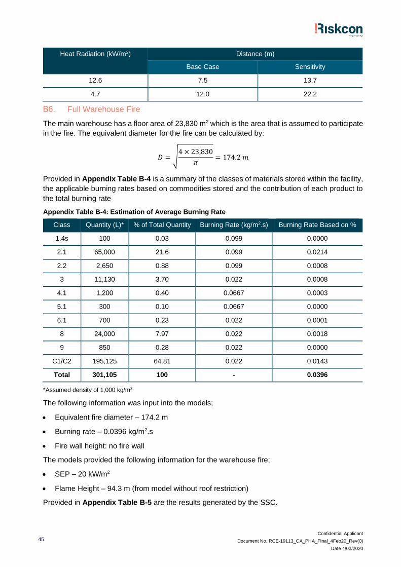
Confidential Applicant
Document No. RCE-19113_CA_PHA_Final_4Feb20_Rev(0)
Date 4/02/2020
45
Heat Radiation (kW/m2) Distance (m)
Base Case Sensitivity
12.6 7.5 13.7
4.7 12.0 22.2
B6. Full Warehouse Fire
The main warehouse has a floor area of 23,830 m2 which is the area that is assumed to participate
in the fire. The equivalent diameter for the fire can be calculated by:
𝐷 = √4 × 23,830
𝜋= 174.2 𝑚
Provided in Appendix Table B-4 is a summary of the classes of materials stored within the facility,
the applicable burning rates based on commodities stored and the contribution of each product to
the total burning rate
Appendix Table B-4: Estimation of Average Burning Rate
Class Quantity (L)* % of Total Quantity Burning Rate (kg/m2.s) Burning Rate Based on %
1.4s 100 0.03 0.099 0.0000
2.1 65,000 21.6 0.099 0.0214
2.2 2,650 0.88 0.099 0.0008
3 11,130 3.70 0.022 0.0008
4.1 1,200 0.40 0.0667 0.0003
5.1 300 0.10 0.0667 0.0000
6.1 700 0.23 0.022 0.0001
8 24,000 7.97 0.022 0.0018
9 850 0.28 0.022 0.0000
C1/C2 195,125 64.81 0.022 0.0143
Total 301,105 100 - 0.0396
*Assumed density of 1,000 kg/m3
The following information was input into the models;
• Equivalent fire diameter – 174.2 m
• Burning rate – 0.0396 kg/m2.s
• Fire wall height: no fire wall
The models provided the following information for the warehouse fire;
• SEP – 20 kW/m2
• Flame Height – 94.3 m (from model without roof restriction)
Provided in Appendix Table B-5 are the results generated by the SSC.

Confidential Applicant
Document No. RCE-19113_CA_PHA_Final_4Feb20_Rev(0)
Date 4/02/2020
46
Appendix Table B-5: Heat Radiation Impacts from a Full Warehouse Fire
Heat Radiation (kW/m2) Distance (m)
35 Maximum heat flux is 20*
23 Maximum heat flux is 20*
12.6 36.0
4.7 81.0
* Research conducted in relation to large fires (Ref. [15]) indicates that where a large fire occurs, it is difficult
for complete combustion to occur towards the centre of the fire due to the lack of air being unable to reach
the centre of the flames. Hence, combustion tends to occur effectively at the fire surface, but poorly
towards the centre of the fire. This generates large quantities of black smoke, which shields the flame
surface as the smoke from the centre of the fire escapes towards the outer fire surface. The research
presented in Lees (Ref. [14]) indicates that fires will generate a SEP within a range of between 20 kW/m2
for larger fires and 130 kW/m2 for smaller fires. Hence, a full warehouse fire would be of significant
dimensions, generating large quantities of black smoke, shielding the flames at the fire surface. Hence,
for the analysis of a full warehouse fire in this study, an SEP value of 20 kW/m2 has been used.
B7. Full Warehouse Fire and Smoke Emission
During the fire, uncombusted toxic products may be present in the smoke plume or toxic bi-products
may be generated which will be dispersed in the smoke plume. It is necessary to assess the
associated impacts of the smoke plume downwind of the facility as it may have far reaching impacts
on the wider community. When assessing the downwind impacts of the fire plume, the main
contributors to the dispersion are:
• The fire size (diameter) and energy released as convective heat
• The atmospheric conditions such as wind speed, relative humidity, atmospheric stability and
ambient temperature.
These parameters interact to determine the buoyancy of the smoke plume (vertical rise) which is
controlled by the convective energy within the smoke plume in addition to the atmospheric
conditions. The atmospheric conditions will vary from stable conditions (generally night time) to
unstable conditions (high insolation from solar radiation) which results in substantial vertical mixing
which aids in the dispersion. Contributing to this is the impact of wind speed which will limit the
vertical rise of a plume but may exacerbate the downwind impact distance.
The atmospheric conditions are classified as Pasquill Guifford’s Stability categories which are
summarised in Appendix Table B-6 (Ref. [15]).
Appendix Table B-6: Pasquill’s Stability Categories
Surface wind
speed at 10 m
height (m/s)
Insolation Night
Strong Moderate Slight Thinly overcast
or ≥50% cloud
<50% cloud.
<2 A A-B B - -
2-3 A-B B C E F
3-5 B B-C C D E
5-6 C C-D D D D

Confidential Applicant
Document No. RCE-19113_CA_PHA_Final_4Feb20_Rev(0)
Date 4/02/2020
47
Surface wind
speed at 10 m
height (m/s)
Insolation Night
Strong Moderate Slight Thinly overcast
or ≥50% cloud
<50% cloud.
>6 C D D D D
Generally, the most onerous conditions are F conditions which result in stable air masses and
typically have inversion characteristics. Inversion characteristics occur when a warm air mass sits
above a cold air mass. Typically, hot air will rise due to lower density than the bulk air; however, in
an inversion, a warm air mass sits above the cooler denser air; hence, as the warm air rises through
the cold mass it hits a ‘wall’ of warmer air preventing vertical mixing above this point. In a fire
scenario, the hot smoke plume will cool as it rises; however, if it encounters an inversion, it will
begin to run along this boundary layer preventing vertical mixing and allowing the smoke plume to
spread laterally for substantial distances.
A smoke plume is buoyant, and will disperse laterally and vertically as it rises essentially following
a Gaussian dispersion as shown in Appendix Figure B-2 (Ref. [15]).
Appendix Figure B-2: Co-ordinate System for Gas Dispersion
Ian Cameron, professor of Risk Engineering at the University of Queensland, has developed a risk
assessment tool known as Risk Assessor produced by DAESIM Technologies. The tool has
numerous risk engineering applications; however, the component of interest for this assessment is
the smoke plume modelling from fire scenarios. The model has been developed based on a
Gaussian dispersion model accounting for modifications to the plume drag coefficients required to
model a plume dispersion from a warehouse fire (Ref. [15]).
The model requires several inputs which have been summarised in Appendix Table B-7 with the
associated value input as part of this modelling exercise. As noted, the more onerous conditions
occur during stable air conditions which allow far reaching effects with reduced dispersion due to
low air velocities and vertical mixing. The industry standard for modelling this scenario is selection
of F1.5 (F stability at 1.5 m/s wind velocity) which has been adopted for this assessment.
Appendix Table B-7: Input Data for Plume Gaussian Dispersion
Input Selected Values Justification
Max burning rate (kg/m2.s) 0.0396 Taken from full warehouse fire above
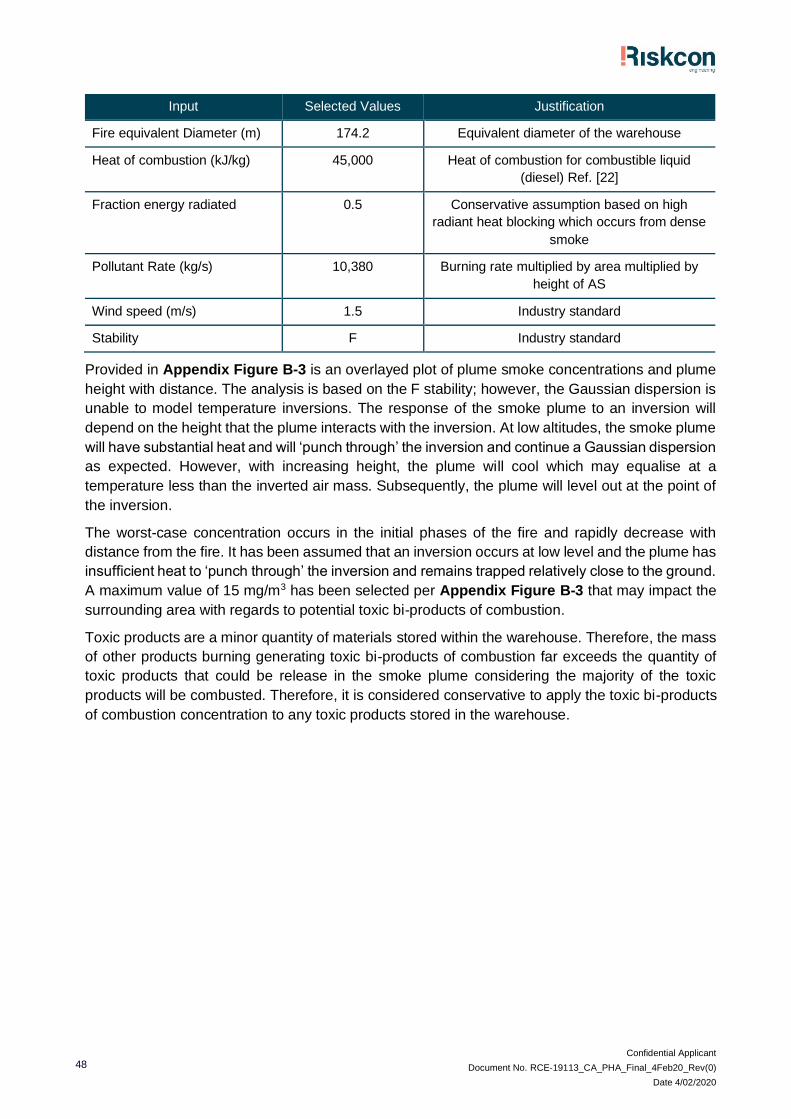
Confidential Applicant
Document No. RCE-19113_CA_PHA_Final_4Feb20_Rev(0)
Date 4/02/2020
48
Input Selected Values Justification
Fire equivalent Diameter (m) 174.2 Equivalent diameter of the warehouse
Heat of combustion (kJ/kg) 45,000 Heat of combustion for combustible liquid
(diesel) Ref. [22]
Fraction energy radiated 0.5 Conservative assumption based on high
radiant heat blocking which occurs from dense
smoke
Pollutant Rate (kg/s) 10,380 Burning rate multiplied by area multiplied by
height of AS
Wind speed (m/s) 1.5 Industry standard
Stability F Industry standard
Provided in Appendix Figure B-3 is an overlayed plot of plume smoke concentrations and plume
height with distance. The analysis is based on the F stability; however, the Gaussian dispersion is
unable to model temperature inversions. The response of the smoke plume to an inversion will
depend on the height that the plume interacts with the inversion. At low altitudes, the smoke plume
will have substantial heat and will ‘punch through’ the inversion and continue a Gaussian dispersion
as expected. However, with increasing height, the plume will cool which may equalise at a
temperature less than the inverted air mass. Subsequently, the plume will level out at the point of
the inversion.
The worst-case concentration occurs in the initial phases of the fire and rapidly decrease with
distance from the fire. It has been assumed that an inversion occurs at low level and the plume has
insufficient heat to ‘punch through’ the inversion and remains trapped relatively close to the ground.
A maximum value of 15 mg/m3 has been selected per Appendix Figure B-3 that may impact the
surrounding area with regards to potential toxic bi-products of combustion.
Toxic products are a minor quantity of materials stored within the warehouse. Therefore, the mass
of other products burning generating toxic bi-products of combustion far exceeds the quantity of
toxic products that could be release in the smoke plume considering the majority of the toxic
products will be combusted. Therefore, it is considered conservative to apply the toxic bi-products
of combustion concentration to any toxic products stored in the warehouse.

Confidential Applicant
Document No. RCE-19113_CA_PHA_Final_4Feb20_Rev(0)
Date 4/02/2020
49
Appendix Figure B-3: Plume Concentration and Plume Height vs Distance
Provided in Appendix Table B-8 is a summary of several toxic products of combustion which may
be present in the smoke plume and their acceptable concentration of exposure for the Acute
Exposure Guideline Levels (AEGL). These levels provide guidance on exposure concentrations for
general populations, including susceptible populations over a range of exposure times to assist in
the assessment of releases which may result in a toxic exposure.
Provide below is a summary of the AEGL tiers of exposure:
• AEGL-3 is the airborne concentration, expressed as parts per million (ppm) or milligrams per
cubic meter (mg/m3), of a substance above which it is predicted that the general population,
including susceptible individuals, could experience life-threatening health effects or death.
• AEGL-2 is the airborne concentration (expressed as ppm or mg/m3) of a substance above
which it is predicted that the general population, including susceptible individuals, could
experience irreversible or other serious, long-lasting adverse health effects or an impaired
ability to escape.
• AEGL-1 is the airborne concentration (expressed as ppm or mg/m3) of a substance above
which it is predicted that the general population, including susceptible individuals, could
experience notable discomfort, irritation, or certain asymptomatic non-sensory effects.
However, the effects are not disabling and are transient and reversible upon cessation of
exposure.
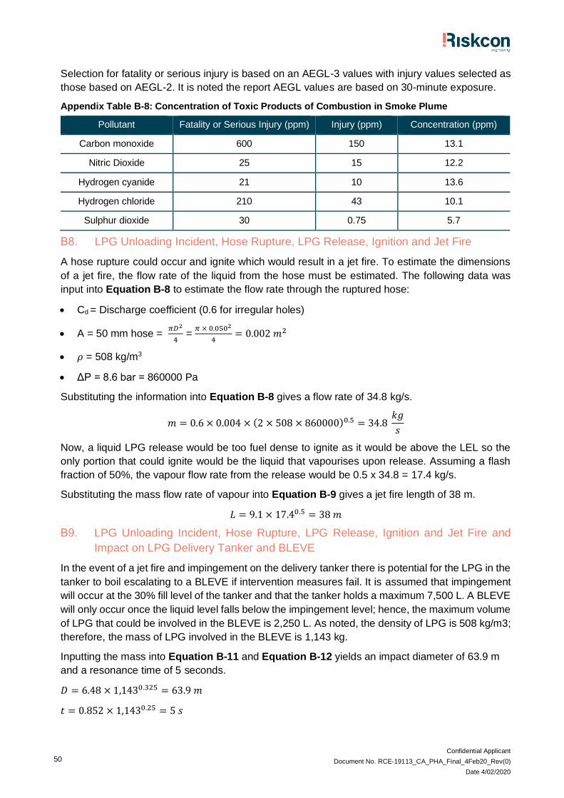
Confidential Applicant
Document No. RCE-19113_CA_PHA_Final_4Feb20_Rev(0)
Date 4/02/2020
50
Selection for fatality or serious injury is based on an AEGL-3 values with injury values selected as
those based on AEGL-2. It is noted the report AEGL values are based on 30-minute exposure.
Appendix Table B-8: Concentration of Toxic Products of Combustion in Smoke Plume
Pollutant Fatality or Serious Injury (ppm) Injury (ppm) Concentration (ppm)
Carbon monoxide 600 150 13.1
Nitric Dioxide 25 15 12.2
Hydrogen cyanide 21 10 13.6
Hydrogen chloride 210 43 10.1
Sulphur dioxide 30 0.75 5.7
B8. LPG Unloading Incident, Hose Rupture, LPG Release, Ignition and Jet Fire
A hose rupture could occur and ignite which would result in a jet fire. To estimate the dimensions
of a jet fire, the flow rate of the liquid from the hose must be estimated. The following data was
input into Equation B-8 to estimate the flow rate through the ruptured hose:
• Cd = Discharge coefficient (0.6 for irregular holes)
• A = 50 mm hose = 𝜋𝐷2
4 =
𝜋 × 0.0502
4= 0.002 𝑚2
• 𝜌 = 508 kg/m3
• ΔP = 8.6 bar = 860000 Pa
Substituting the information into Equation B-8 gives a flow rate of 34.8 kg/s.
𝑚 = 0.6 × 0.004 × (2 × 508 × 860000)0.5 = 34.8 𝑘𝑔
𝑠
Now, a liquid LPG release would be too fuel dense to ignite as it would be above the LEL so the
only portion that could ignite would be the liquid that vapourises upon release. Assuming a flash
fraction of 50%, the vapour flow rate from the release would be 0.5 x 34.8 = 17.4 kg/s.
Substituting the mass flow rate of vapour into Equation B-9 gives a jet fire length of 38 m.
𝐿 = 9.1 × 17.40.5 = 38 𝑚
B9. LPG Unloading Incident, Hose Rupture, LPG Release, Ignition and Jet Fire and
Impact on LPG Delivery Tanker and BLEVE
In the event of a jet fire and impingement on the delivery tanker there is potential for the LPG in the
tanker to boil escalating to a BLEVE if intervention measures fail. It is assumed that impingement
will occur at the 30% fill level of the tanker and that the tanker holds a maximum 7,500 L. A BLEVE
will only occur once the liquid level falls below the impingement level; hence, the maximum volume
of LPG that could be involved in the BLEVE is 2,250 L. As noted, the density of LPG is 508 kg/m3;
therefore, the mass of LPG involved in the BLEVE is 1,143 kg.
Inputting the mass into Equation B-11 and Equation B-12 yields an impact diameter of 63.9 m
and a resonance time of 5 seconds.
𝐷 = 6.48 × 1,1430.325 = 63.9 𝑚
𝑡 = 0.852 × 1,1430.25 = 5 𝑠
Confidential Applicant
Document No. RCE-19113_CA_PHA_Final_4Feb20_Rev(0)
Date 4/02/2020
51
B10. LPG unloading Incident, Hose Rupture, LPG Release, Ignition and Jet Fire and
Impact on LPG Tank and BLEVE
In the event of a jet fire and impingement on the above ground tank there is potential for the LPG
in the tanker to boil escalating to a BLEVE if intervention measures fail. It is assumed that
impingement will occur at the 30% fill level of the tank. The tank holds 7,500 L; hence, at the 30%
fill level 2,250 L of LPG is involved in the BLEVE. As noted, the density of LPG is 508 kg/m3;
therefore, the mass of LPG involved in the BLEVE is 1,143 kg.
Inputting the mass into Equation B-11 and Equation B-12 yields an impact diameter of 63.9 m
and a resonance time of 5 seconds.
𝐷 = 6.48 × 1,1430.325 = 63.9 𝑚
𝑡 = 0.852 × 1,1430.25 = 5 𝑠

Confidential Applicant
Document No. RCE-19113_CA_PHA_Final_4Feb20_Rev(0)
Date 4/02/2020
52
Appendix C
Warehouse Fire Frequency Estimation
Confidential Applicant
Document No. RCE-19113_CA_PHA_Final_4Feb20_Rev(0)
Date 4/02/2020
53
C1. Estimation of the Frequency of a Full Warehouse Fire
A review of readily available warehouse fire frequency information was conducted, and a number
of direct sources were identified. These were:
• Health and Safety Executive (HSE) in the United Kingdom [Hymes & Flynn, UKAEA - SRD/HSE
R578, 2002] – this document lists the major warehouse fire frequency to be 2.5x10⁻³ p.a.;
• Baldwin, Accident Analysis and Prevention (Vol.6) – indicates a serious fire frequency in
warehouses to be in the order of 1x10⁻³ p.a.;
• Environmental Impact Assessment Report for the Commission of Inquiry into Proposed
Manufacturing Plant by WR Grace Australia Ltd., Kurnell, Sydney, October 1987 – indicates a
fire frequency of 4.6x10⁻³ per warehouse year; and
• VROM 2005, Guidelines for quantitative risk assessment CPR 18E (Purple Book), Publication
Series on Dangerous Substances (PGS 3), The Netherlands. – 4x10⁻⁴ p.a.
It is noted that the mix of overseas data and local data (albeit some is dated) correlates to indicate
a fire frequency in warehouses to be in the order of 1x10⁻³ to 4x10⁻⁴. The data presented in the
reports reviewed was for general warehouses, where stringent controls for spill and ignition sources
(such as flame and explosion proof fittings, bunding, smoking and naked flame controls, isolation
of power supplied on warehouse closure, etc.) were not part of the warehouse hazard controls.
Hence, for a DG warehouse, containing specific ignition and fire control systems, it would be
expected that a major fire would occur with a lesser frequency than that of general warehouses.
Notwithstanding this, to ensure a conservative assessment has been provided within the study, the
estimated initiating fire frequency for the DHL facility has been estimated as 1x10⁻³ p.a. (i.e. the
upper end of the range).
Selected Initiating Fire Frequency = 1x10⁻³ p.a.