pro-balance 1 1/4 in. brass manifold · compatibility with the flushing fluid, ... - 1 1/4 in. npt...
TRANSCRIPT

PRO-BALANCE® 1 1/4 IN. BRASS MANIFOLDProduct Instructions
1. Scope 3
2. Product Overview 3
3. Technical Data 5
4. Mounting the Manifold 7
5. Installing RAUPEX Pipes 8
6. Flushing and Filling Radiant Circuits 10
7. Balancing the Manifold 11
CONTENTS
For updates to this publication and the most current technical instructions, safety information and manufacturer’s recommendations, visit na.rehau.com/resourcecenter
2

1. SCOPE
This guide provides instruction regarding PRO-BALANCE 1 1/4 in. manifold installation and operation. Manifolds may only be installed, adjusted and maintained by an appropriately licensed installer of radiant systems.
Throughout this document, the signal word NOTICE is used to help you avoid property damage. We cannot warn of all hazards; you must also use your own good judgment.
2. PRODUCT OVERVIEW
PRO-BALANCE 1 1/4 in. manifolds are used for distributing and regulating the volume of flow in radiant systems. The PRO-BALANCE 1 1/4 in. manifold is equipped with visual flow gauges on the supply side and circuit balancing isolation valves on the return side. Note the following:- Must be operated using heating water, which is free of corrosive
particles or other contaminants that can damage the manifold.- Maximum permissible continuous operating pressure is
87 psi (6 bar) at 176°F (80°C).- Maximum permissible test pressure is 145 psi (10 bar) at water
temperature < 86°F (30°C) and maximum ambient temperature 104°F (40°C).
- Use manifolds only as intended in order for REHAU’s PEXa Limited Warranty to apply.
NOTICE: A damaged manifold may leak, causing system failure and property damage.
- Do not expose manifold to harmful chemicals, aggressive water conditions or any external influences that may cause damage to manifold materials.
- Use appropriate antifreeze agents when below freezing conditions exist.
- Properly insulate manifold and/or locate manifold so as to avoid condensation.
- Do not install the manifold using connectors or accessories made by other manufacturers.
Impact of System Fluid on Manifold and System ComponentsThe installer must have an understanding of local water conditions and how the makeup of the system fluid can impact the lifetime and performance of the system components. The composition of the system fluid has a major impact on the potential for corrosion within the complete system. The likelihood of corrosion and failure of system components can be greatly reduced by using suitable water quality and ensuring proper system operation.
The local installer and design engineer must have an understanding of the potential for water-side corrosion. In certain cases, various forms of corrosion can occur which include functional impairments to the system, system leakage, clogging of system components, impairment of heat transmission and flow noise.
3

Field experience has shown that risk of corrosion damage is greatly reduced by the following measures:- System must be completely sealed and operated with heating water
without additives. If water treatment is necessary, the contractor should ensure the additives to the system including antifreeze and corrosion inhibitors, and that system flushing chemicals do not lead to corrosion of the system components.
- Propylene glycol and ethylene-based glycols at maximum 50% concentration are recommended within temperature pressure ratings shown in Fig. 2 in case freeze protection of the system is necessary. Alcohol-based glycols are not permitted because they can lead to system failure.
- Materials such as wax or mineral oils, threading oils or incompatible air compressor oils must not be introduced into the system.
- Installer must review the complete list of water-contact materials in the PRO-BALANCE 1 1/4 in. manifold (see Table 1) to ensure compatibility with the flushing fluid, system fluid and additional makeup water.
- Manifold must be installed in a non-corrosive environment.- If there are known local conditions that could lead to corrosion of the
system components, the installer must consult with a water quality expert experienced in corrosion control of piping systems. If there are no known standards for ensuring proper water quality, then the German engineering standard, VDI 2035 Prevention of Damage in Water Heating Installations, should be referenced. (English version of VDI 2035 available for purchase at www.beuth.de or contact REHAU for assistance).
- System fluid should also comply with RPA guidelines for hydronic radiant heating systems and CSA B214-16 Installation Code for Hydronic Heating Systems.
Manifold ComponentsEach PRO-BALANCE 1 1/4 in. manifold comes complete with the following:- Installation instructions- 1 1/4 in. NPT supply and return manifold isolation ball valves with
thermometer sockets and flat gaskets- Two 1 1/4 in. BSPP brass end caps with gaskets- Visual flow gauges (0-4 GPM) on supply side- Circuit balancing/isolation valves on return side- Mounting brackets- Four drywall screws- Vent key- Manifold circuit chart
In addition, you will need:- R-20 connectors for the size of RAUPEX® you are using - Mini thermometers (Art. 250218, sold separately)- Brass manifold air vent ball drain combination set
(Art. 250226, sold separately) - 1 1/4 in. brass manifold adapter fittings
(Art. 298986-001, sold separately)- Adjustable wrench- 1 1/4 in (32 mm) wrench for 3/8, 1/2 and 5/8 in. R-20 connectors- 1 1/2 in (38 mm) wrench for 3/4 in. fittings- 2 in (50 mm) wrench
4
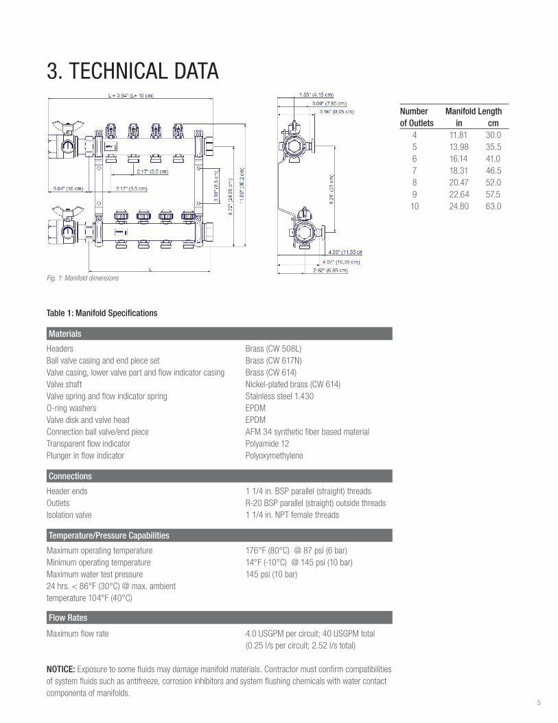
3. TECHNICAL DATA
Materials
Headers Brass (CW 508L)Ball valve casing and end piece set Brass (CW 617N)Valve casing, lower valve part and flow indicator casing Brass (CW 614)Valve shaft Nickel-plated brass (CW 614)Valve spring and flow indicator spring Stainless steel 1.430O-ring washers EPDMValve disk and valve head EPDMConnection ball valve/end piece AFM 34 synthetic fiber based materialTransparent flow indicator Polyamide 12Plunger in flow indicator Polyoxymethylene
Connections
Header ends 1 1/4 in. BSP parallel (straight) threadsOutlets R-20 BSP parallel (straight) outside threads Isolation valve 1 1/4 in. NPT female threads
Temperature/Pressure Capabilities
Maximum operating temperature 176°F (80°C) @ 87 psi (6 bar)Minimum operating temperature 14°F (-10°C) @ 145 psi (10 bar)Maximum water test pressure 145 psi (10 bar) 24 hrs. < 86°F (30°C) @ max. ambienttemperature 104°F (40°C)
Flow Rates
Maximum flow rate 4.0 USGPM per circuit; 40 USGPM total (0.25 l/s per circuit; 2.52 l/s total)
NOTICE: Exposure to some fluids may damage manifold materials. Contractor must confirm compatibilities of system fluids such as antifreeze, corrosion inhibitors and system flushing chemicals with water contact components of manifolds.
Number Manifold Length of Outlets in cm 4 11.81 30.0 5 13.98 35.5 6 16.14 41.0 7 18.31 46.5 8 20.47 52.0 9 22.64 57.5 10 24.80 63.0
Fig. 1: Manifold dimensions
Table 1: Manifold Specifications
5
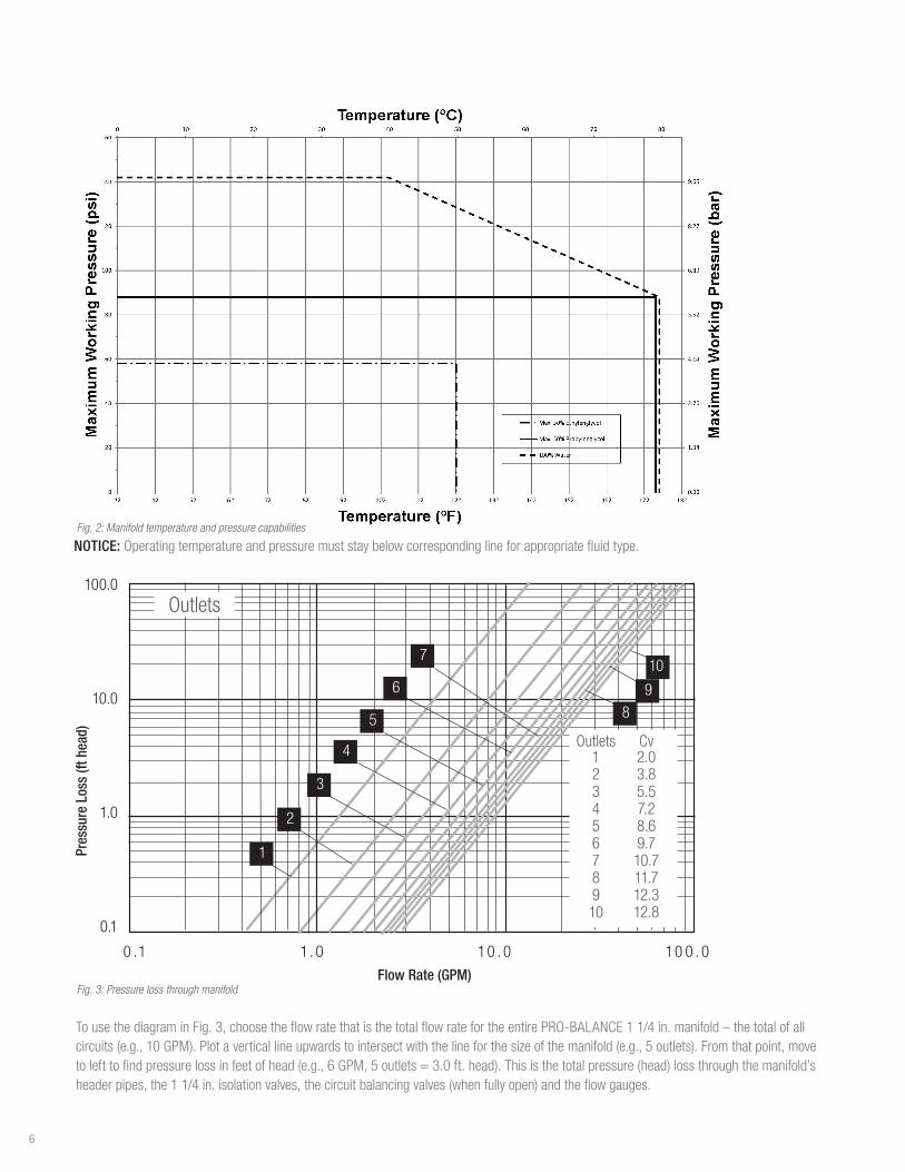
NOTICE: Operating temperature and pressure must stay below corresponding line for appropriate fluid type.
100.0
10.0
1.0
0.1
0 .1 1. 0 10 . 0 10 0 . 0
1
2
3
4
5
6
7
Outlets Cv 1 2.0 2 3.8 3 5.5 4 7.2 5 8.6 6 9.7 7 10.7 8 11.7 9 12.3 10 12.8
Outlets
89
10
Pres
sure
Los
s (ft
hea
d)
Flow Rate (GPM)Fig. 3: Pressure loss through manifold
To use the diagram in Fig. 3, choose the flow rate that is the total flow rate for the entire PRO-BALANCE 1 1/4 in. manifold – the total of all circuits (e.g., 10 GPM). Plot a vertical line upwards to intersect with the line for the size of the manifold (e.g., 5 outlets). From that point, move to left to find pressure loss in feet of head (e.g., 6 GPM, 5 outlets = 3.0 ft. head). This is the total pressure (head) loss through the manifold’s header pipes, the 1 1/4 in. isolation valves, the circuit balancing valves (when fully open) and the flow gauges.
Fig. 2: Manifold temperature and pressure capabilities
6

4. MOUNTING THE MANIFOLDNOTICE: An improperly installed manifold can leak, causing system failure and property damage. To minimize risk of leaks:- Must use included steel mounting brackets, which provide a secure
mount, proper alignment and isolation of vibration and noise.- Do not use thread sealant tape or pipe dope on the manifold
outlets.- Do not over tighten connections.
1. Install the manifold in its final position prior to connecting the RAUPEX pipes.
- Manifold may be installed in a REHAU steel heating manifold cabinet, on a wall or on a temporary support frame.
- Manifold may be mounted in any orientation (i.e., inverted, horizontal, sideways).
- Manifold must be level and have adequate clearance on the sides for pipe connections.
- Minimum clearance is 16 in (40 cm) between the bottom of the manifold and the top of the finished floor.
- Steel mounting bracket and screws are provided.
2. Attach the 1 1/4 in. isolation ball valves and the air vent drain valves by sliding the flange nut over the large tab on the flange, then over the small tab. Hand tighten the nut onto the end of the header.
- Red-handle valve goes on the supply header.- Blue-handle valve goes on the return header.- Use the slip flanges and flat gaskets provided.- Align valves with the thermometer housings facing the front.
Note: If you will be using an air test, slightly wet the flat gaskets with water before attaching each valve.
3. Gently tighten the nuts with a 2 in (50 mm) wrench, without crushing the flat gaskets (1/4 to 1/2 turn).
4. Close the 1 1/4 in. isolation valves for pressure testing and to keep out foreign objects.
7

5. INSTALLING RAUPEX PIPES
RAUPEX pipes are connected to the manifold using REHAU R-20 manifold compression fittings (sold separately). - For 3/8, 1/2, 5/8 and 3/4 in. fittings, the R-20 connector includes
insert with O-ring, split brass ring and compression nut- For 3/4 in. fittings, the R-20 connector also includes an R-20 x 1 in.
bushing
It is easiest to connect each pipe to the manifold working left to right and starting with the upper (supply) header first.
Note: If using PVC bend guides, make sure guides are slid over pipe and adjusted to the proper height before attaching the R-20 connector. 1. Cut pipe squarely using a pipe cutter.
2. Slide the R-20 compression nut and split ring over the pipe. Then push in the insert fitting all the way to the top of the pipe.
NOTICE: Do not use any damaged R-20 connectors or rubber O-rings. Damaged parts may cause leakage.
3. Push the conical end of the R-20 connector all the way into the appropriate outlet of the manifold. For 3/4 in. fittings, first attach the R-20 x 1 in. bushing to the manifold outlet with the hex end of the bushing closest to the header. This should be done hand tight.
4. Hand tighten the compression nut, making sure the pipe and fitting are pushed all the way in.
NOTICE: Do not use thread sealant tape or pipe dope on the manifold outlets. These materials may prevent a proper seal, causing leaks.
8

5. While holding the hex end of the manifold outlet with an adjust-able wrench, turn the compression nut no more than a half turn beyond hand tight.
.
- For 3/8, 1/2 and 5/8 in. connections, use a 1 1/4 in (32 mm) wrench.
- For the 3/4 in. connections, use a 1 1/2 in (38 mm) wrench.
NOTICE: Do not over tighten. Use approximate force of 12 Nm or 9 lb ft. Over tightening will damage the O-ring or the manifold outlet, causing leaks.
6. If you have unused circuit outlets on the manifold, use the R-20 Circuit Outlet Cap (Article No. 250209-C).
9
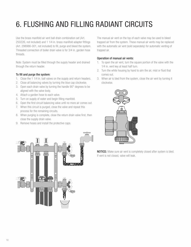
6. FLUSHING AND FILLING RADIANT CIRCUITS
Use the brass manifold air vent ball drain combination set (Art. 250226, not included) and 1 1/4 in. brass manifold adapter fittings (Art. 298986-001, not included) to fill, purge and bleed the system. Threaded connection of boiler drain valve is for 3/4 in. garden hose threads.
Note: System must be filled through the supply header and drained through the return header.
To fill and purge the system: 1. Close the 1 1/4 in. ball valves on the supply and return headers.2. Close all balancing valves by turning the blue cap clockwise.3. Open each drain valve by turning the handle 90° degrees to be
aligned with the valve body.4. Attach a garden hose to each valve. 5. Turn on supply of water and begin filling manifold. 6. Open the first circuit balancing valve until no more air comes out.7. When this circuit is purged, close the valve and repeat this
process for the remaining circuits.8. When purging is complete, close the return drain valve first, then
close the supply drain valve. 9. Remove hoses and install the protective caps.
The manual air vent on the top of each valve may be used to bleed trapped air from the system. These manual air vents may be replaced with the automatic air vent (sold separately) for automatic venting of trapped air.
Operation of manual air vents:1. To open the air vent, turn the square portion of the valve with the
1/4 in. vent key at least half turn.2. Turn the white housing by hand to aim the air, mist or fluid that
comes out.3. When air is bled from the system, close the air vent by turning it
clockwise.
NOTICE: Make sure air vent is completely closed after system is bled. If vent is not closed, valve will leak.
10
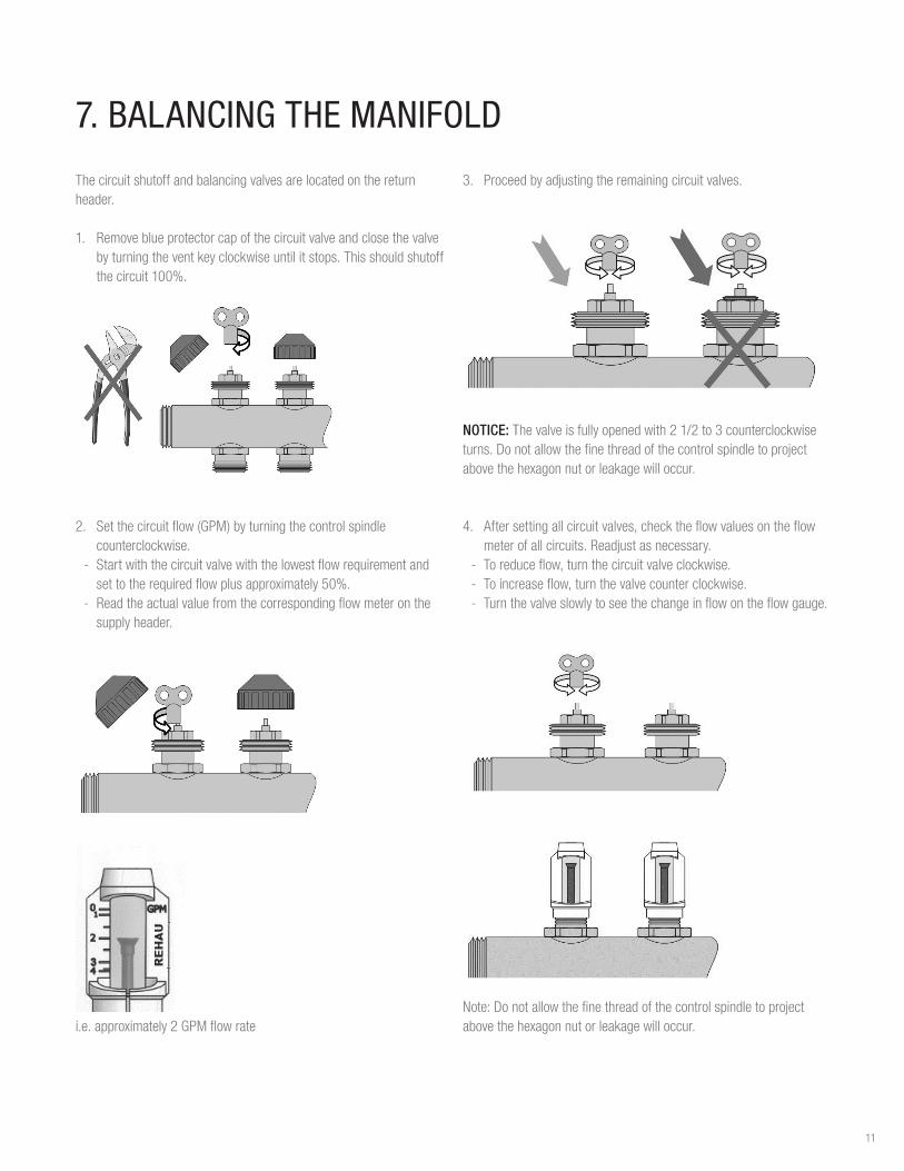
7. BALANCING THE MANIFOLD
The circuit shutoff and balancing valves are located on the return header.
1. Remove blue protector cap of the circuit valve and close the valve by turning the vent key clockwise until it stops. This should shutoff the circuit 100%.
2. Set the circuit flow (GPM) by turning the control spindle counterclockwise.
- Start with the circuit valve with the lowest flow requirement and set to the required flow plus approximately 50%.
- Read the actual value from the corresponding flow meter on the supply header.
i.e. approximately 2 GPM flow rate
3. Proceed by adjusting the remaining circuit valves.
NOTICE: The valve is fully opened with 2 1/2 to 3 counterclockwise turns. Do not allow the fine thread of the control spindle to project above the hexagon nut or leakage will occur.
4. After setting all circuit valves, check the flow values on the flow meter of all circuits. Readjust as necessary.
- To reduce flow, turn the circuit valve clockwise. - To increase flow, turn the valve counter clockwise. - Turn the valve slowly to see the change in flow on the flow gauge.
Note: Do not allow the fine thread of the control spindle to project above the hexagon nut or leakage will occur.
11
100.0
10.0
1.0
0.1
0 . 1 1 . 0 1 0 . 0
0.25
0.5
1.0
1.5
2.0
2.5
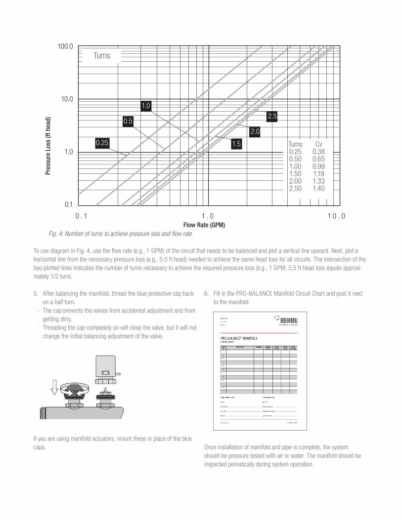
Turns Cv 0.25 0.38 0.50 0.65 1.00 0.99 1.50 1.19 2.00 1.33 2.50 1.40
Turns
Fig. 4: Number of turns to achieve pressure loss and flow rate
To use diagram in Fig. 4, use the flow rate (e.g., 1 GPM) of the circuit that needs to be balanced and plot a vertical line upward. Next, plot a horizontal line from the necessary pressure loss (e.g., 5.5 ft.head) needed to achieve the same head loss for all circuits. The intersection of the two plotted lines indicates the number of turns necessary to achieve the required pressure loss (e.g., 1 GPM, 5.5 ft.head loss equals approxi-mately 1/2 turn).
Pres
sure
Los
s (ft
hea
d)
Flow Rate (GPM)
5. After balancing the manifold, thread the blue protective cap back on a half turn.
- The cap prevents the valves from accidental adjustment and from getting dirty.
- Threading the cap completely on will close the valve, but it will not change the initial balancing adjustment of the valve.
If you are using manifold actuators, mount these in place of the blue caps.
6. Fill in the PRO-BALANCE Manifold Circuit Chart and post it next to the manifold.
Once installation of manifold and pipe is complete, the system should be pressure tested with air or water. The manifold should be inspected periodically during system operation.

13

For updates to this publication, visit na.rehau.com/resourcecenterThe information contained herein is believed to be reliable, but no representations, guarantees or warranties of any kind are made as to its accuracy, suitability for particular applications or the results to be obtained therefrom. Before using, the user will determine suitability of the information for user’s intended use and shall assume all risk and liability in connection therewith. © 2017 REHAU 855.662 11.2017