process engineering and designdesign.che.vt.edu/publication/74_liuquantrillecheng1993... ·...
TRANSCRIPT

Ind . Eng. Chem. Res. 1990,29, 2227-2241 2227
PROCESS ENGINEERING AND DESIGN
Studies in Chemical Process Design and Synthesis. 9. A Unifying Method for the Synthesis of Multicomponent Separation Sequences with Sloppy Product Streams
Y. A. Liu,* Thomas E. Quantrille, and Shueh-Hen Chengt Department of Chemical Engineering, Virginia Polytechnic Institute and Sta te University, Blacksburg, Virginia 24061 -021 I
This paper presents a unifying method for the synthesis of flowsheets for multicomponent separations with sloppy product streams, in which some components being separated may simultaneously appear in two or more product streams. Our goal is to synthesize good separation sequences by using all-sharp, all-sloppy, and both sharp and sloppy separators. After introducing some basic tools and concepts for problem representation, feasibility analysis, and separation synthesis, we propose a unifying classification of all multicomponent separation-sequencing problems into four classes and suggest proper approaches to solving each class of synthesis problems. While we can apply our method with different synthesis tools such as optimization, we use six rank-ordered heuristics in a number of industrial separation problems. The resulting sequences represent good candidates for detailed flowsheet optimization. Our method can be easily applied by hand calculations by practicing engineers, and it has been implemented as an expert system using PROLOG.
1. Introduction This work deals with the synthesis of alternative flow-
sheets for separating a multicomponent feed into several sloppy product streams, in which some components in the feed simultaneously appear in two or more product streams. As an example, Table I specifies a problem of separating a four-component mixture of light hydrocarbons (components A-D) into four sloppy product streams (products Pl-P4), designated as example 1; Figure 1 il- lustrates three different separation sequences that give the desired product streams in example 1.
Figure l a represents an all-sharp sequence S1, consisting of three sharp (S) separations in which each component being separated appears almost completely in one and only one product. Sharp separations correspond to very high recovery fractions of the light key in the overhead (denoted by dLK) and of the heavy key in the bottoms (denoted by ~HK); that is, 0.98 I d L K I 1.0 and 0.98 I ~ H K I 1.0. Se- quence S1 begins with a sharp split ABC/D in separator V3, followed by a sharp split AB/C in separator V2' with a portion of the feed being bypassed around the separator to directly form a part of the overhead (denoted by a prime in V2'). The sequence ends with a sharp split A/B in separator Vl", where the double prime indicates bypassing two portions of the feed around the separator to directly form parts of both overhead and bottoms products.
Sequence S1 includes three separators ( S = 3). This number corresponds to the apparent minimum number of separators, Smin, for example 1 that is specified by the following equation (Cheng and Liu, 1988, designated he rea f t e r as p a r t 8): Smin = min (C,P) - 1 = min (44) - 1 = 4 - 1 = 3 (1)
* To whom correspondence should be addressed. 'Present address: Glitsch, Inc., P.O. Box 660053, Dallas, TX
72566.
Table I. Feed and Product Specifications in Example 1" component flow rate,
mol/h prod flow desired prod streams A B C D rate, mol/h P4 P3 P2 P1
0 0 0 15 15 0 0 20 10 30
10 12.5 0 0 22.5 15 12.5 5 0 32.5
component flow rate 25 25 25 25 100
"Data taken from Nath (1977). Components A, B, C, and D are, respectively, n-butane, n-pentane, n-hexane, and n-heptane with normal boiling points of -0.5, 36.1, 68.7, and 98.4 O C . For a feed mixture at 92.2 OC and 466.1 kPa, equilibrium ratios are KA = 2.46, KB = 1.00, Kc = 0.47, and KD = 0.21 or the relative volatilities are OIAB = 2.46, (YBC = 2.13, cxAC = 5.23, CYCD = 2.24, and CYBD = 4.76.
in feed, mol/h
In the equation, C is the number of components and P is the number of products.
Figure l b shows a four-separator, a l l - s loppy sequence SL1. This sequence consists of four sloppy (SL) or low- recovery separations, in which some components in the feed simultaneously appear in two or more products. Sequence SL1 begins with a sloppy split ABC/CD in separator H3. The overhead from H3 goes to another sloppy separator HB'(AB/BC) and then to Hl'(A/AB), while the bottoms from H3 goes to HI'(CD/D). This all-sloppy sequence includes one more separator than Smi, (=3). In this work, we are interested in the synthesis of sloppy sequences that have at most one more separator than other competing minimum-separator sequences. With less stringent component recovery fractions specified in sloppy separations, an all-sloppy sequence could cost less than a competing minimum-separator sequence.
Figure IC depicts a four-separator, mixed-separation sequence MS2 that utilizes both s loppy and sharp sepa-
0888-5885/90/2629-2227$02.50/0 0 1990 American Chemical Society

2228 Ind. Eng. Chem. Res., Vol. 29, No. 11, 1990
--j Pl(l5A, 12 58 5C) '- - 7 4 . 5 A
20A - 2.58 20B
E 5 c ~ , 2.5A~vl,.
I I I I I I 15 I I I
1 I I 10
/i ./ i
2.5B 10Al &V2' P2(10A,1258)
P4
f H4(P1'21'3/P4)
- P3 (ZOC, 10D)
I I 20 I 1 :
I I 5 (bl '
FEED
, P3
! e H3(P1'21' P34) I
I
1. Pl(15A. 12.58, 5C) P1' * 3.75A
I
I 12.5 I
1
I 10 1 1 2 5
25D 1 ,
! P1 I I I
I ! I I PZ I I
c- HZ(P1'2rP1'34) ?A ~
8.188 .32B
15 1.258 P1' -1 2.75C
I I I I I
I I I I I
c Hl(Pl'P21'34)
I P1'
+ P2(1OA, 12.58)
-- P3 (2OC. 10D)
20c 25D
12.8C
16D 'Fi______, 150 P4(15D)
rPl(15A 1258,SC) 2.5A t
I
r--- 4
l a
- P4(15Dl 15D
Figure 1. (a) An all-sharp, three-separator sequence for example 1: sequence S1, V3(ABC/D) - V2'(AB/C) - Vl"(A/B). (b) An all- sloppy, four-separator sequence for example 1: (c) A mixed-separa- tion sequence with four separators for example 1:
HY(ABIBC) - Hl'(A/AB) sequence SL1, HS(ABC/CD) <
H4'(C D I D) - VY(AB/C) - VI'(A/B) sequence MS2, HP(ABC/CD) -
V3'(C I D)
rators. This sequence begins with a sloppy split ABC/CD in separator H2. The overhead from H2 goes to a sharp separator V2'(AB/C) followed by another sharp separator Vl'(A/B), while the bottoms from H2 goes to a sharp separator V3'(C/D). When properly designed, a mixed- separation sequence can be competitive in cost compared to a minimum-separator, all-sharp sequence or to an all- sloppy sequence with an equal number of separators.
Product 8 4 c + D Stream A
t I I 1 I
t H 3 ( P 1 2 3 / P 4 ) 10
P3 ,HZ(PlZ/P34)
CL
I 1 I - v1 vz v3
(NBCD) (ABICD) (ABCID)

Ind. Eng. Chem. Res., Vol. 29, No. 11,1990 2229
Table 11. SST for First Splits in Example 1 Represented by Equation 2 separation ovhd/ btm LK/HK A, "C ( d / b ) , ( d / b ) e ( d / b ) , (d/b)D CES
v1 A/BCD = 25/75 A/B 36.6 0.98/0.02f 0.0210.98, 0.02f0.98 0.02/0.98 3.61 v2 ABICD = 50150 B/C 32.6 0.98/0.02 0.98/0.02! 0.02f0.98 0.02/0.98 9.67 v3 ABC/D = 75/25 C/D 29.7 0.98/0.023 0.98/0.02 0.98f0.02 0.02f0.98 2.93 H l b Pl/P234 = 32.5167.5 A/B 36.6 0.610.4 I 0.510.5 I _0,4_1_6/0.584 0.02f0.98 infeasible' H1 Pl/P234 = 32.5167.5 B/C 32.7 _-- - 0.95410.046 0.510.5 I 0.2/0.8---- 0.0210.98 infeasible' H2* P121P34 = 55/45 B/C 32.6 0.9870yCi2--- 0.9810.021 0.210.8 0.001/0.999c 11.7 H2 P12lP34 = 55/45 C/D 29.7 0.98/0.02 0.7310.27 0.210.8 : -6.02/6.%. - infeasible" H3 P123/P4 = 85/15 C/D 29.7 0.98/0.02 -0.3$]6.02 0.98f0.02 0.410.6 2.81
' Infeasible product splits due to undesirable nonkey component distributions. Separations with split keys, that is, Hl(PlfP234) with A/C as LK/HK and HZ(P12fP34) with B/D as LK/HK, are not included due to undesirable nonkey component distributions. 'Dashed horizontal lines denote component-recovery ratios estimated by the Fenske equation. Dashed vertical lines represent the partition between the LK and the HK.
represents the flow rate of a component in the specific product stream bounded by two PLs, and the numerical value of the component molar flow rate is indicated next to each CL. Vertical product lines, denoted by Vl-V3, are used to separate one component from the other. For ex- ample, Vl(A/BCD) represents a split that gives an over- head of component A and a bottoms of components B-D.
In this work, we simplify our problem representation by introducing a component assignment matrix (CAM). Elements of this matrix correspond to component molar flow rates that are indicated next to each CL between two PLs in the CAD. Thus, the CAM for example 1 repre- sented by Figure 2a is
A B C D l5 - H3 (P123/P4)
i - H1 (Pl/P234) - H2 (P12/P34) (2)
1°1
P4 0 0 0 0 20
0 5
F; [li 12.5 P1 15 12.5
t t t V1 v2 v3
(A/BCD) (AB/CD) (ABC/D) In what follows, we o f t en s impli fy our designation of products, PI , P2, P3, ..., in a CAM by 1,2,3, .... The use of the CAM for problem representation greatly facilitates the computer implementation of our synthesis method.
2.2. Feasibility Analysis. Component splits repre- sented by vertical PLs, such as Vl(A/BCD), VB(AB/CD), and V3(ABC/D) in eq 2, are sharp separations. These splits may not directly yield the desired sloppy product streams. For some synthesis problems, we need to blend together two or more products from different vertical component splits, Vj's, to obtain the desired sloppy products. Figure l a illustrates this blending practice.
Product splits represented by horizontal PLs, namely, Hl(Pl/P234), H2(P12/P34), and H3(P123/P4) in eq 2, correspond to either sloppy or sharp separations de- pending on component recovery specifications. A key difference between vertical component splits Vj's and horizontal product splits Hi's is that Vj's are always fea- sible but not all Hi's are technically andlor practically feasible. The feasibility of Hi's depends on (1) the spec- ification of component recovery fractions in the overhead and bottoms, di and bi; (2) the choice of light-key (LK) and heavy-key (HK) components; and (3) the possibility of having significant or undesirable distributions of nonkey components in both the overhead and bottoms. In part 8, we introduced a separation specification table (SST) to aid in the feasibility analysis of Hi's. In this work, we extend the use of the SST to analyze the technical feasi- bility and practicality of both Hi's and Vj's. Table I1 gives an SST for the first splits in example 1 representation by eq 2.
An SST contains the following information: (1) type of separation, Hi's or Vj's; (2) overhead (ovhd or D ) and
bottoms (btm or B); (3) choice of LK and HK components; (4) separation factor between the LK and the HK; ( 5 ) calculated and estimated ratios of component recovery fraction in the overhead to that in the bottoms; and (6) coefficient of ease of separation (CES) defined by the following equation
In this equation, f is the ratio of the molar flow rates of products, B I D or D I B , depending on which of the two ratios is smaller than or equal to unity; A = A T = boil- ing-point difference between key components, or A = IOO('YLK,HK - 1) with CYLK,HK being the relative volatility between the LK and the HK. The logarithmic term in the equation represents the effect of split sloppiness on the ease of separation, mimicking a similar effect on the minimum number of theoretical stages Nmh according to the Fenske equation
(4)
Part 8 described how to calculate component split ratios, (d /b) ' s , listed in an SST based on given component flow rates. Let us consider an example based on eq 2. For split Hl(Pl/P234) with A/B as LK/HK listed in Table 11, we find (d/b)LK = ( d / b ) , = 15/10 (eq 2) = 0.6/0.4 (Table 11)
( d / b ) ~ ~ = ( d / b ) , = 12.5/12.5 (eq 2) = 0.5/0.5 (Table 11)
( ~ / ~ ) H H K z = ( d / b ) , = 0/25 (eq 2) N 0.02/0.98 (Table 11)
Here, HHK2 refers to the second heavier-than-heavy or heavy-key component, and we use a limiting ratio of 0.02/0.98 to approximate the sharp cut represented by the calculated ratio, 0125, for component HHK2 or D.
To estimate the split ratio of a nonkey component in an SST, we take advantage of the fact tht the Fenske equation is applicable to different combinations of light and heavy components such as (LLK2, HK), (LLK1, HK), (LK, HHKl), and (LK, HHK2). Let us consider the first heavy component HHKl or component C resulting from H1- (Pl/P234) with A/B as LK/HK included in Table 11. We use the relative volatilities given in Table I and first apply the Fenske equation to (LK, HK) or (A, B) to find the minimum number of theoretical stages, Nmin:
N . = -
log [(d/b)LK(b/d)HK] N . = mm log ~ L K , H K
- - 1% [ ( ~ / ~ ) L K ( ~ / ~ ) H K I - 1% [ ( d / b ) ~ ( b / d ) ~ l log 'YAB mm log ~ L K . H K
log [(0.6/0.4)(0.5/0.5)] log 2.46
= 0.4504

2230 Ind. Eng. Chem. Res., Vol. 29, No. 11, 1990
We then apply the equation with the calculated value of Nmin to (LK, HHK1) or (A, C):
- - 1% f fAC log 5.23
Since di + bi = 1 for any component i, we can solve the last equation to obtain bc = 0.4159 and dc = 0.5841, or (D/ B ) H H K 1 = ( d / b ) c = 0.416/0.584. In Table 11, we use a dashed horizontal line to characterize this split ratio as an estimated value for heavy component HHKl or component C that results from Hl(Pl/P234) with A/B as LK/HK. This estimated split ratio of (d/b)c = 0.416/0.584 repre- sents a significant distribution of a nonkey component C in both overhead and bottoms. As discussed in part 8, in order to avoid this undesirable distribution of nonkey components in both overhead and bottoms, the designer often needs to use a distillation column with a large num- ber of theoretical stages, resulting in a costly design. We therefore designate Hl(Pl/P234) with A/B as LK/HK as an economically or a practically infeasible split and in- dicate it as “infeasible” under the CES column in Table 11.
We can also apply the shortcut feasibility analysis to other Hi’s or Vfs listed in Table 11. For example, for H2(P12/P34) with B/C as LK/HK, we find ( ~ / ~ ) L L K = ( d / b ) ~ =
( d / b ) ~ ~ = ( d / b ) ~ =
25/0 (eq 2) N 0.98/0.02 (Table 11)
25/0 (eq 2) - 0.98/0.02 (Table 11) ( d / b ) H ~ = (d/b)c = 5/20 (eq 2) = 0.2/0.8 (Table 11)
Here, we use a limiting ratio of 0.98/0.02 to approximate the sharp cut represented by the calculated ratio, 25/0, for components A and D.
As in the case of Hl(Pl/P234), we can apply the Fenske equation to estimate the split ratio of nonkey component HHKl or component D resulting from H2(P12/P34). We
as indicated by a dashed horizontal line in Table I1 for H2(P12/P34) with B/C as LK/HK. We characterize this horizontal product split as “feasible”, because (1) it does not lead to undesirable nonkey component distributions and (2) its component recovery specifications satisfy the following feasibility conditions developed in part 8
find bD e 0.999, dD 0.001, and ( d / b ) D N 0.001/0.999,
... 1 dLLKZ 1 dLLKl L d L K > d H K 1 d H H K 1 1 dHHK2 > ... (5)
or ... 5 bLLK2 5 ~ L L K ~ 5 ~ L K < ~ H K 5 ~ H H K ~ 5 ~ H H K ~ 5 ...
(6) Specifically, for H2(P12/P34) with B/C as LK/HK, Table I1 gives ~ L L K ~ 2 ~ L K > ~ H K > ~ H H K ~
(0.98 = 0.98 > 0.2 > 0.001) ~ L L K ~ 5 ~ L K < ~ H K < ~ H H K ~
(0.02 = 0.02 < 0.8 0.999) For this feasible split, we calculate the CES value listed in Table I1 according to eq 3, or
We should recognize that an improper choice of LK/HK may make a horizontal product split practically infeasible due to undesirable nonkey component distributions. For example, Table I1 shows that using a different set of LK/HK in applying the Fenske equation to H2(P12/P34) results in the following split ratios for nonkey components: (a) B/C as LK/HK
( d / b ) L L K I = ( d / b ) A = 0.98/0.02 ( d / b ) H H K 1 = ( d / b ) D O.OOI/O.999
(b) C/D as LK/HK ( d / b ) L L K S = ( d / b ) A = 0.98/0.02
( d / b ) ~ ~ ~ 1 = ( d / b ) , 0.73/0.27 In part 8, we demonstrated that if the split ratio of a
light component, LLK, predicted by the Fenske equation at total reflux is greater than or equal to a limiting ratio of 0.98/0.02, then this light component does not signifi- cantly distribute in both overhead and bottoms under common operating reflux ratios RD = 1.1-1.5RDqin. This observation is also true for a heavy component, HHK, that has a split ratio not greater than a limiting ratio of 0.02/0.98. For H2(P12/P34) with B/C as LK/HK, ( d / b)LLK1 and ( d / b ) H H K i satisfy these limiting conditions and this split is feasible. By contrast, H2(P12/P34) with C/D as LK/HK results in a nonkey-component split ratio, ( d / b)LLK1 N 0.73/0.27 < 0.98/0.02. Therefore, choosing C/D as LK/HK makes H2(P12/P34) infeasible.
We mention one additional item of interest that is re- lated to the always feasible, vertical component splits Vl-V3. We approximate the sharp cut of a light-key (LK) or a lighter-than-light-key (LLK) component in the ov- erhead and bottoms by a limiting split ratio of 0.98/0.02. Likewise, we approximate the sharp cut of a heavy-key (HK) or a heavier-than-heavy-key (HHK) component by 0.02/0.98. For example, for V2(AB/CD) with B/C as LK/HK listed in Table 11, we find ( ~ / ~ ) L L K = ( d / b ) ~ =
25/0 (eq 2) N 0.98/0.02 (Table 11)
25/0 (eq 2) N 0.98/0.02 (Table 11)
0/25 (eq 2) N 0.02/0.98 (Table 11)
0/25 (eq 2) N 0.02/0.98 (Table 11) To summarize, using an SST together with the CAM
provides a simple means to analyze the technical feasibility of both horizontal product splits Hi’s and vertical com- ponent splits Vj’s. This analysis identifies technically and/or practically infeasible splits resulting from unde- sirable component recovery specifications and nonkey component distributions.
2.3. Pseudoproduct Transformation and Stream Bypassing. Consider again example 1 represented by eq 2. An all-sloppy sequence for this example, such as se- quence SL1, Figure lb, may consist of the following can- didates of Hi’s: (a) first splits, Pl/P234, P12/P34, P123/P4; (b) second splits, Pl/P23, P12/P3, P2/P34, and P23/P4; and (c) third splits, Pl /P2, P2/P3, and P3/P4. Unfortunately, not all of these Hi’s are technically and/or practically feasible. For example, split H(PlIP2) may be represented by the following submatrix of eq 2:
A B C
(d/b)LK = ( d / b ) , =
( d / b ) ~ ~ = ( d / b ) c =
( ~ / ~ ) H H K = ( d / b ) ~ =

Ind. Eng. Chem. Res., Vol. 29, No. 11, 1990 2231
The presence of an all-component-inclusive product suggests the possibility of bypassing a portion of the feed stream around the separator to directly form a part of the product. For example, H4’(CD/D) or H4’(P3/P4) in se- quence SL1 depicted in Figure l b involves bypassing to product P3. We are limited in the amount of bypassing allowed by the material balance. Component D is the limiting component, and we can bypass a t most 10 mol/h of D to P3. If we bypass 90% of that amount, i.e., 9 mol/h of D, and 7.2 mol/h of C, we get
4 0 15 C D C D
-(7.2C,9D) to P3 4 0 [12.8 1+41 3 [20 103- H4
Choosing A/B as LK/HK for H(PlIP2) gives ( d / b ) L K = ( d / b ) , = 15/10 = 0.6/0.4
( d / b ) ~ ~ = ( d / b ) ~ = 12.5/12.5 = 0.5/0.5
(d /b )HHK1 = (d/b)c = 5/0 0.98/0.02 These component recovery specifications do not satisfy the feasibility conditions, eqs 5 and 6, or
~ L K > ~ H K > ~ H H K ~
bLK < ~ H K < ~ H H K ~
(0.6 > 0.5 3 0.98) (0.4 < 0.5 # 0.02)
Therefore, H(Pl /P2) is technically infeasible; the corre- sponding product set, (Pl/P2), represents an infeasible product set for an all-sloppy sequence for example 1.
We can convert the infeasible product set, (Pl,P2), into an equivalent feasible product set (Pl*,P2,Pl’) by splitting part of product P1 into two pseudoproducts, P1* and Pl’. Figure 2b illustrates this pseudoproduct transformation, and the corresponding CAM is
A R n
L
t t t v1 v2 v3
Since all component recovery fractions corresponding to component flow rates in the equivalent product set (Pl*,P2,Pl’,P3,P4) satisfy eqs 5 and 6, splits H(Pl*,P2), H(P2/P1’ ), H(Pi’/P3), and H(P3/P4) are technically feasible. After carrying out these splits, we can readily obtain the desired product P1 by blending together pseudoproducts P1* and Pl’.
A disadvantage of confining the sequence of separating a multicomponent mixture to using only horizontal product splits Hi’s is that whenever an infeasible product split exists, stream splitting together with pseudoproduct transformation increases the number of separators by one for each pseudoproduct introduced. In the following, we first describe the concept of stream bypassing and its significance and then illustrate another approach to dealing with the problem of infeasible product splits.
In Figure lb, we represent the all-sloppy sequence SL1 for example 1 by the following
SL 1 H3(ABC IC D) (8 )
Using our standard notation for horizontal product splits, we now repreent sequence SL1 in terms of the equivalent feasible product set (Pl*,P2,Pl‘,P3,P4) as
H2‘(AB/BC) - Hl’(AIAB) /
H4’(CDID)
H2’( P1’2/P1’) - P I ’( PI‘/P2) 4
SL1 H3(P1*21’/P34) - (9) H4’( P3/P4)
We use sequence SL1 to illustrate below when stream bypassing should be used and what advantages may be gained from bypassing.
From eq 7, we write the submatrix representing the bottoms from H3(P1*211/P34):
rl n c/ u
CAM(H3,btm) = [2: ti] - H4 (10)
t
v3 We see that product P3 contains all the components (namely, C and D) in the feed. We therefore call product P3 an all-component-inclusive product.
t v3
H4 feed = 45 mol/h
c
v3 H4’ feed = 28.8 mol/h
(104 This bypassing reduces the feed rate from 45 mol/h (H4) to 28.8 mol/h (H4’). Stream bypassing can greatly reduce the mass load of downstream separation.
We illustrate another significance through bypassing the maximum amount, i.e., 100% of distributed component D in product P3. We bypass 10 mol/h of D together with 8 mol/h of C to get
n n n n
-(8C,lOD) to P3 4
t v3
H4 feed = 45 mol/h
t v3
H4’ feed = 27 mol/h
(lob) As seen, stream bypassing may convert a sloppy split, such as H4 ( f V 3 ) represented by eq 10, to a sharp one, such as H4’(=V3) specified by eq lob. In fact, the right-hand side of eq 10b shows that both H4’(P3/P4) and V3(C/D) represent an identical sharp separation, giving component C as overhead and component D as bottoms with the following component recovery specifications:
( d / b ) L K = (d/b)c = 12/0
( d / b ) H K = ( d / b ) ~ = 0/15
0.98/0.02
0.02/0.98 Finally, stream bypassing is an effective tool to handle
the problem of infeasible product splits without increasing the number of separators as in the case of applying stream splitting together with pseudoproduct transformation. Consider, for example, a three-component sloppy separa- tion problem defined by Aggarwal and Floudas (1989). The CAM representing the problem is
A B C 2 20 1 [go ;: ::] -
t t v1 v2
(11)
where components A, B, and C are propane, isobutane, and n-butane, respectively. Split Hl(Pl /P2) is practically infeasible with either A/B or B/C as LK/HK due to the undesirable nonkey component distributions. For exam- ple, when LK = A and HK = B, we find from eq 11
( d / b ) L K = (d/b), = 80/20 = 0.8/0.2 ( d / b ) H K = (d/b)B = 30/70 = 0.3/0.7
(d /b )HHK = (d/b)c = 20/80 = 0.2/0.8 While these component recovery specifications do satisfy the feasibility conditions, eqs 5 and 6, Le., d L K > d H K > dHHK (0.8 > 0.3 > 0.2) and ~ L K < bHK < ~ H H K (0.2 < 0.7

2232 Ind. Eng. Chem. Res., Vol. 29, No. 11, 1990
< 0.81, there is a significant amount of nonkey component HHK or component C in the overhead with d H H K = 0.2. The latter leads to a costly design. We therefore consider Hl(Pl/P2) a practically infeasible split. Applying stream splitting together with pseudoproduct transformation to Hl(Pl IP2) results in the need of two sloppy separators. In addition, eq 11 shows that products P1 and P2 can be obtained by using two sharp separators, V 1 and V2.
Actually, the separation problem represented by eq 11 can be solved by only one sloppy separator. Both products P1 and P2 in eq 11 are all-component-inclusive. Thus, bypassing 100% limiting component C in product P1 and 90% limiting component A in product P2 gives
2 20 70 80 -(18A,18B,18C) to [* ‘]-Hl p2
P1 1 80 30 20 -(20A,20B,20C) tg
t t v1 v2
H1 feed = 300 mol/h
t ’ VI v2
HI” feed = 186 mol/h Now the resulting horizontal split Hl’’(PlIP2) is feasible with the following component recovery specifications
(d/b)LK = (d/b), = 60/2 = 0.968/0.032 ( d / b ) H K = ( d / b ) ~ = 10/52 = 0.16/0.84 ( d / b ) H H K = (d/b), = 0/62 N 0.02/0.98
(12)
(13) (14)
A comparison of eqs 12-14 clearly indicates of that stream bypassing can reduce both the mass load of separation and the number of separators. The fact that this separation problem requires only one sloppy separator, but two sharp separators, provides excellent incentive to systematically consider the relative merits of both sloppy and sharp separations in the preliminary design of multicomponent separation processes. The tools and concepts described in the preceding sections provide the simple and effective means to aid in this consideration.
2.4. Classification of Multicomponent Product Sets. To facilitate the synthesis of good initial sequences for a given separation problem, we broadly divide multi- component product sets into four classes. Our classifica- tion involves a comparison of (a) the number of products, P (b) the number of components, C; and (c) the rank r or pseudorank r’ of the component assignment matrix.
A. Rank and Pseudorank of the CAM. The CAM is a P X C matrix with elements vtjl representing the flow rate of thej th component in the zth product (i = 1,2, ..., P; j = 1, 2, ..., C). This matrix may also be expressed by its product vectors v, as follows:
I a I L -1 Lfi1 J
From the matrix theory, we know that P product vectors vl, v2 ..., vp are linearly independent if the CAM has a rank of P. This implies that the CAM contains one P X P submatrix having a nonzero determinant, and the deter- minant of any submatrix with P + 1 or more rows is zero. For example 1, the order of the largest nonzero determi- nant in the 4 X 4 CAM of eq 2 is four; that is, rank r of this CAM is four.
In general, rank r of a CAM is not greater than the smaller value of either the number of components C or the number of products P that is,
r I min (C,P) (16)
When r is less than P, there are only r linearly independent product vectors, and the remaining P - r product vectors can be expressed in terms of these r product vectors:
vk = CklVl + ck2v2 + + CkrVr (k = 1, 2, ..., P - r ) (17)
In the equation, ckl, c k 2 , ..., ckr are constants. If these constants are greater than zero, then P - r product vectors vk (k = 1, 2, ..., P - r ) can be obtained by appropriate blending of r linearly independent product vectors, vl, v2, ..., v,. This reduces the size of the original product set. When any of the constants, ckl, ck2, ..., Ckr, is negative, however, we cannot obtain P - r product vectors vk from r linearly independent product vectors, vl, v2, ..., v,, without requiring an additional separator to accommodate for the negative constant ck’ ( j = 1, 2, ..., r). This possibility leads us to define a pseudorank, denoted by r’. Specifically, r’ is equal to the rank r of the CAM plus the number of product vectors that cannot be expressed as a linear com- bination of r independent product vectors by nonnegative coefficients c k , ( j ’ = 1, 2, ..., r). This definition gives the relationship
r l r ‘ I P (18)
As an example of pseudorank, let us consider a CAM for a sloppy separation problem taken from Muraki et al. (1986):
A B C D
CAM
6.4 9.6 6.4 6.4 3.2
6 10 2 0 2
(19)
For this problem, we have four components (C = 4) and five products (P = 5), and the rank of CAM is four ( r = 4). The latter implies that there are only four independent product vectors. Choosing vl, v2, v3, and v4 as independent product vectors, we write eq 17 as
v5 = CRlVl + c5*v2 + c53v3 + c54v4 =
Since c53 is negative and v3 is also an independent product, we find pseudorank r’ = r + 1 = 4 + 1 = 5. Equation 18 becomes r (4) < r ’ (=5) = P (=5).
B. Classification of Product Sets (Types). On the basis of relative magnitudes of r ’ (pseudorank of the CAM), C (number of components), and P (number of products), we broadly divide multicomponent product sets into four classes: (a) class 1, r’ = P = C; (b) class 2, r’ 5 P < C; (c) class 3, r’ < P = C; and (d) class 4, C < P with class 4a, r ’ = C < P, class 4b, C < r’= P, and class 4c, r’ < C < P, Figure 3 illustrates this classification, relating the pseu-
2.25V1 0 V 2 + ( - O . ~ ) V , + 0.25V4

Ind. Eng. Chem. Res., Vol. 29, No. 11, 1990 2233
r ' = P = C
number of products and C, the number
of wmponentr
' r' I number of Independent
product. (r' 4 P = C)
CLASS 1
products Independent products (r' c P < C)
(C < P) - CLASS 2 CLASS 2 CLASS 4
Figure 3. Classification of product types into four classes based on the pseudorank of component assignment matrix (CAM).
CLASS 3
dorank r 'to the number of independent products. Table I11 gives examples for each class of product sets, taken from reported studies of the synthesis of multicomponent sep- aration sequences with sloppy product streams.
Class 3 (r' C P = C) in Table I11 refers to a separation problem that is slightly different from example 1 specified by eq 2. This modified example 1 has a CAM with P = C = 4 as follows:
1 1
A B C D ~4 1-25 25 25 101
1 1
0 20 0 5
Fill: 12.5 P1 15 12.5
(20)
In this example, there are only three independent products (P l , P2, and P3); both the rank ( r ) and pseudorank ( r ' ) of the CAM are equal to three. Product P4 can be formed by blending together products Pl-P3.
An example of class 4a (r' = C C P) is the multicom- ponent separation problem in making polymer solvent blends with controlled dielectric constants. A CAM rep- resenting this type of problem is
A B C P4 10 10 5 E [: ; I] (21)
P1 5
with components A, B, and C being tetrahydrofuran, ethyl
chloride, and n-hexane, respectively. For this example, we have P4 = P1 + P2 + P3 and r' = C (=3) < P (=4).
A minor change of eq 21 gives an example of class 4c (r' C C C P) in Table 111:
A B C P4 10 15 Fi [: 8" ;] (22)
P1 5
Here, we have P3 = P1 + P2, P4 = 2(P1) + P2, and r'(=2) c c (=3) c P (=4).
2.5. A Unifying Synthesis Method. Figure 4 shows the steps of a unifying method for the synthesis of good all-sharp, all-sloppy, and mixed-separation sequences that utilize a minimum number or a nearly minimum number of separators. We can implement the unifying method with a variety of synthesis tools such as heuristics and optimization. In this work, we adopt the rank-order heuristics of part 8 for horizontal product splits Hi's to aid in the selection of both Hi's and vertical component splits Vj's for a given separation problem represented by a CAM. Figure 5 illustrates our procedure based on the CAM and rank-ordered heuristics. The latter heuristics include the following: M1, favor ordinary distillation and remove mass-separating agent first; M2, avoid vacuum distillation and refrigeration; S1, remove corrosive and hazardous components fist; S2, perform difficult separations last; C1, remove most plentiful product first; C2, favor 50/50 split.

2234 Ind. Eng. Chem. Res., Vol. 29, No. 11, 1990
Table 111. Classification of Product Types examples of multicomponent separation-sequencing problems
class 1: r’ = P = C (a) separation of light hydrocarbons by ordinary distillation, example 1 (C = 4, P = 4)’ specified in Table I; see part product type
8, Aaaarwal and Floudas (1989). Bamaooulos et al. (1988). and Nath (1977)
class 2: r’ 5 P < C
class 3: r ’< P = C
class 4: C < P (4a) r ’ = C < P
(4b) C < r’ = P (4c) r ‘< C < P
(b) example 1 (C = 3, P = 3, F = 2) in Fioudas (1987) (c) example 1 (C = 5, P = 5) in Muraki and Hayakawa (1988) (a) fractionation of refinery light ends, example 2A (P = 7, C = 13) of part 8; see also Tedder (1984) (b) fractionation in refinery saturates-gas plant, example 2B (P = 7, C = 14) of part 8 see also Watkins (1979) (c) examples 1 and 2 ( P = 2, C = 3) in Aggarwal and Floudas (1989) (d) examples 2 and 3 (P = 2, C = 4) and example 4 (P = 2, C = 5) in Floudas (1987); see also Table VI (e) example 1 (P = 3, C = 4, F = 2) and examples 2 and 3 ( P = 2, C = 5) in Floudas and Anastasiadis (1988) (f) example 1 ( P = 2, C = 5) in Muraki and Hayakawa (1984, 1987) (9) example 2 (P = 2, C = 4) in Muraki et al. (1986) modified example 1, with one product capable of being formed by blending of other products; see eq 20; compare it
multicomponent separations in making polymer solvent blends, giving solvent products of controlled dielectric constants; see eq 21
example 1 (C = 4, P = 5) in Muraki et al. (1986); see eq 19 similar to (4a); see eq 22
with eq 2
a The default value of F, the number of feed streams, is one.
Table IV. SST for Nest Splits in Sequence SI for Example 1 Represented by Equation 25 separation ovhd/btm LK/HK A, “ C ( d l b ) A ( d l b h (dlb)c CES . .. . - , -
V1’ AIBC = 20140 AIB 36.6 0.9810.02 ! 0.02/0.98 0.0210.98 5.41 V2‘ Ab/C = 40120 B j C 32.6
Part 8 gives complete descriptions of these heuristics for choosing horizontal product splits Hi’s.
3. Illustrative Examples and Discussion 3.1. “Class 1” Product Type: r’ = P = C. Example
1, specified in Table I and by eq 2, involves the separation of a four-component mixture (C = 4) of hydrocarbons (nC4-nC7) into four sloppy product streams (P = 4). Both the rank ( r ) and pseudorank ( r ’ ) of the CAM of eq 2 are four. From steps 1-4 of Figure 3, we designate sloppy products of example 1 as “class 1”.
We describe the development of separation sequences for this class 1 problem in the following three subsections: (A) incorporating all-sharp sequences; (B) incorporating both sharp and sloppy (Le., mixed-separation) sequences; and (C) incorporating all-sloppy sequences.
A. All-Sharp Separation Sequences. Step 1 of Figure 4 synthesizes all-sharp separation sequences with C - 1 or 3 separators for example 1. To carry our this synthesis, we apply the heuristic procedure of Figure 5 as follows.
A.1. Sequence S1. Step 1. See eq 2. Steps 2-4. Equation 2 reveals no all-component-inclu-
sive product. Step 5. See Table 11, particularly for vertical component
splits Vl-V3, which are always feasible. Step 6. Table I1 shows that normal boiling-point dif-
ferences for Vl-V3 are large enough to use ordinary dis- tillation (heuristic Ml). To avoid vacuum distillation and refrigeration (heuristic M2), we prefer a high-pressure operation of the debutanizer, Vl(A/BCD). This follows because butane (component A) has a relatively low normal boiling point of -0.5 “C.
Steps 7 and 8. Not applicable, since there is no corrosive and hazardous component and boiling-point differences for Vl-V3 are large.
Step 9. Equation 2 shows that the most plentiful product is P1 consisting of component A-C. Thus, heu- ristic C1 favors V3(ABC/D) with CES = 2.93 (see Table 11). Although VP(AB/CD) has a larger CES of 9.67, we do not choose this split first because our heuristics are
0.9810.02 0.9810.02 j 0.0210.98 4.84
rank-ordered; i.e., heuristic C1 overrules heuristic C2.
and bottoms: Step 10. Split VS(ABC/D) gives the following overhead
A B C 31-0 o 201
CAM(V3,ovhd) =
D
CAM(V3,btm) = 4 VI (24)
To further separate the overhead from V3, we apply the heuristic procedure of Figure 5 to eq 23 as follows.
Steps 2-4. Equation 23 shows that product P1 is all- component-inclusive. While it would be desirable to by- pass 90-100% of the distributed components, A and B, the small flow rate of component C (5 mol/h) in P1 dictates that we can at most bypass 5 mol/h of A, 5 mol/h of B, and 5 mol/h of C to product P1. This bypass gives
B C 0
CAM’(V3,ovhd) = L
t t V1’ V2’
Step 5. See Table IV. Steps 6-10. According to eq 25, the most plentiful
product is P2 consisting of components A and B. Fol- lowing heuristic C1, we choose V2’(AB/C) first, resulting in the following overhead:
The bottoms from V2’(AB/C) consists of 20 mol/h of component C going to product P3.
Further separation of the overhead from V2‘, eq 26, by the heuristic procedure of Figure 5 is fairly straightforward.

Ind. Eng. Chem. Res., Vol. 29, No. 11, 1990 2235
a minor change in the preceding synthesis of sequence S1. Specifically, we ignore heuristic C1 and follow heuristic C2. Instead of choosing V3(ABC/D) first to obtain an overhead with components A, B, and C that are present in the most plentiful product P1 as in sequence S1, we favor VB(AB/CD) with the largest CES of 9.67. From eq 2, V2(AB/CD) gives the following overhead and bottoms:
start
sa par a I ion s e q u m c n to give (C - I ) separators
I
I Yes I
sequences to glvo s c I
A a11 horizontal
splits feaslble 6 practlcai with at
least one LWnK on Initial CAM or after stream \ ./
sequences to glve (r ’ . IbS=C or
Transform CAM making all horizontal splits feasible with at
least one LWKH on new
sequencers to glve (r’ . I ) < S 5 C
reparators-
l o Rlgorous deslgn optlmiration 6
costing of proposed
Figure 4. Unifying method for multicomponent separation se- quencing with sloppy product streams. In the figure, S is the num- ber of separators used.
We bypass 37.5% of the feed to P1 and 50% of the feed to P2, resulting in a sharp component split Vl”(A/B):
A B A B ;[i,5 y ] (2% 2 10 12.5 -(lOA,lOR) to P2 ~
1 [lo 7.51 -(7.5A,7.5B) to P1
t V1”
Equations 23-27 give the following all-sharp sequence, S1, shown in Figure la: S1 V3(ABC/D) - V2’(AB/C) - Vl”(A/B) (28)
A.2. Additional All-Sharp Sequences. We develop an alternative sequence by referring to eq 2 and making
(1) overhead CAM(V2,ovhd) CAM”(V2,ovhd)
A B -(lOA,lOB) to P2 2[0 i .51 (29)
-(12.5A,12.5B) to P1 1 2.5 t
v 1 t
V1“
(2) bottoms CAM( V2,btm) CAM’(V2,btm)
C D C D 4 0 4
1 1 5
-(lOC,lOD) to P3. ; k t ‘i] (30)
t t v 3 V3’
In eqs 29 and 30, we have also included the CAMS after stream bypasses according to steps 2-4 of Figure 5. Car- rying out the resdting splits Vl”(A/B) and V3’(C/D) gives the following all-sharp sequence, S2, shown in Figure 6a:
s2 V 1 ”(A I 6)
V3‘(C/D) VP(AB/CD) . (31)
Further applications of the heuristic procedure of Figure 5 to eq 2 and Table I1 result in three more all-sharp se- quences: s3 V3(ABC/D) - Vl’(A/BC) - V2(B/C) (32) S4 Vl(A/BCD) - V2(B/CD) - V3’(C/D) (33) S5 Vl(A/BCD) - V3(BC/D) - V2’(B/C) (34) Figure 6, b-d, illustrates these sequences.
B. Mixed-Separation Sequences. We now return to Figure 4. Steps 2-7 suggest mixed-separation sequences with r ’ - 1 separators. We apply these steps to example 1 as follows.
Step 2. As noted previously, r’ = C = 4. Thus, we find P ’ # C + 1 and continue with step 5.
Step 5. P ‘ < C + 2. Step 6. See Table 11, noting the CES ranking of the
following feasible splits: split LK/HK CES
9.67 3.61 2.93 2.81
11.7 H2(P12/P34) B/C V2(AB/CD) B/C Vl(A/BCD) A/B VB(ABC/D) C/D H3(P123/P4) C/D
Step 7. To synthesize mixed-separation sequences, we
B.1. Sequence MS1. Steps 1-8. These steps are essentially identical with
those previously applied to the synthesis of sequence S1. The only difference appears in step 5, since we must now consider both horizontal product splits Hi’s and vertical component splits Vj’s. The feasible splits resulting from step 5 of Figure 5 are the five splits (H2, V2, V1, V3, and H3) listed above according to the CES ranking.
Step 9. Heuristic C1 favors V3(ABC/D), which gives an overhead consisting of components A-C that are present in the most plentiful product P1. We do not choose ini-
use the heuristic procedure of Figure 5 as follows.

2236 Ind. Eng. Chem. Res., Vol. 29, No. 11, 1990
START 7 h thoro an
Inclurivo Rocalcuhte distrlbutd componrnt product?
No
5 Ut. SST to riiminatr Infraribh or impractical 8plltr bPud on cmpononl m o v r r y apoclflcatbnr and nonkoy component distribution8
1 6
U r heuristics MI and M2 to r l e c t reparation mothodr and conditlonr
I
C2 with CES to find derirod split
Figure 5. Heuristic procedure for choosing a horizontal product split or a vertical component split on a CAM for implementing the unifying method of Figure 4.

Ind. Eng. Chem. Res., Vol. 29, No. 11, 1990 2237
bypass resulting in an overhead represented by eq 25. We rewrite the latter equation in the form below to facilitate the subsequent considerations of both Hi’s and Vi’s in mixed-separation sequences.
A B C FEED P2 (lOA, 12.58)
25D
I . ‘ * P3(ZOC,lODI
25D 15D
P4(1SD) 15D
PZ(l0A. 12581
4 25C v3
i 1OA
*Pl11OA. 12 581
258 25C ZOC
250
P l i l S D i 15D
Figure 6. Additional all-sharp separation sequences with three separators for example 1: - Vl”(AI6)
V3’(C/ D) (a) sequences2 (=LIS), VP(ABICD) - (b) sequence53 (=MSl), VS(A6CID) - Vl’(AI6C) - VP(E/C)
(c) sequenceS4. Vl(AIBCD) - VS(E/CD) - V3’(C/D)
(d) sequenceS5, VI(AI6CD) - V3(6C/D) - VS‘(E/C).
tially H2(P12/P34), V2(AB/CD), and Vl(A/BCD) with larger CES values because heuristic C1 overrules heuristic c 2 .
Step 10. Split V3(ABC/D) gives the following overhead and bottoms: CAM (V3,ovhd) = eq 23 and CAM (V3, btm) = eq 24. We apply the heuristic procedure of Figure 5 to eq 23 to further separate the overhead from V3 as follows.
Steps 2-4. These steps are identical with those previ- ously applied in the synthesis of sequence S1, with stream
L
1 t V1‘ V2’
Step 5. See Table V. Steps 6-10. Table V and eq 35 show that both V1’-
(A/BC) and H2’(P12/P3) [or H2’(ABC/C)] have the highest CES of 5.41 and are equally good according to heuristic C2. We choose Vl’(A/BC) as our next separation, resulting in the following bottoms:
B C
(36) - H1‘ CAM(Vl’,btm) =
t V2‘
The overhead from Vl’(A/BC) consists of 20 mol/h of component A that is to be split into two equal portions of 10 mol/h each going into products P1 and P2.
To further apply the heuristic procedure of Figure 5 to separate the bottoms from Vl’, eq 36, we recognize that choosing an initial split Hl’(BC/B) requires a subsequent separation H2’(B/C). By contrast, both V2’ and H2’ represent an identical, one-step sharp separation of 20 mol/h of C from 20 mol/h of B. We therefore prefer V2’(B/C) and split the resulting overhead into two portions with 7.5 and 12.5 mol/h of B going into products P1 and P2, respectively. This leads to the following sequence that is the same as the all-sharp sequence S3 shown in Figure 6b: MS1( =S3)
V3(ABC/D) - Vl’(A/BC) - V2(B/C) (32)
The above example illustrates an important feature of the mixed-separation synthesis method. While the method permits the use of both sharp and sloppy separators, it may actually generate separation sequences utilizing only sharp splits as in sequence MS1 (=S3) or sequences incorporating only sloppy splits. B.2. Additional Mixed-Separation Sequences. In
the above use of the heuristic procedure of Figure 5 to synthesize sequence MS1, we favor V3(ABC/D) with CES = 2.93, over H2(P12/P34) with CES = 11.7, and thus to obtain an overhead with components A-C to form a part of the most plentiful product P1 according to heuristic C1. If we ignore heuristic C1 and follow heuristic C2, we can apply the synthesis method of Figure 5 to obtain the following mixed-separation sequence, MS2, shown in Figure IC: - VZ(AE/C) - VI’(AIB) MS2 HP(AEC/CD) . (37)
V3’(C/D)
Applications of the mixed-separation synthesis scheme may generate additional sequences. An example is that shown in Figure 6a:
V 1 ”(A/ E)
V3”(C/D) MS3(=S2) VZ(AE/CD) < (38)

2238 Ind. Eng. Chem. Res., Vol. 29, No. 11, 1990
Table V. SST for Next Splits in Sequence MS1 for Example 1 Represented by Equation 35 seoaration ovhdlbtm LK/HK A,”C ( d l b ) n ( d l b h ( d l b ) c CES
36.6 32.6 36.6 32.7 32.6
V1’ A/BC = 20140 AIB V2’ ABjC = 40120 B/C H1‘ PlIP23 = 17.51425 A/B H1’ Pl /P23 = 17.5/42.5 BlC H2’ P12/P3 = 40120 B/C
Table VI. Feed and Product Specifications in Example 3 O component flow rate,
mol/h product flow desired oroduct streams A B C D rate, mollh
P2 P1
5 10 4 10 29 10 10 6 5 31
component flow rate 15 20 10 15 60
“Examples 2A and 2B are specified in part 8. A = propane (normal boiling point, -42.1 “C), B = isobutane (-11.7 “C), C = n-butane (-0.5 OC), and D = isopentane (27.8 “C). Difficulty of ith “sharp“ separation between two key components: DAB (or D,) = 2.5, DBC (or D2) = 3.0, and DcD (or D3) = 1.5. Data taken from Floudas (1987).
C. All-Sloppy Separation Sequences. Returning to Figure 4, we see from steps 8 and 9 the need to synthesize all-sloppy sequences for example 1. We also find that the number of separators can vary from r’ - 1 to C, that is, from 3 to 4. To carry out this synthesis, we apply the heuristic procedure of Figure 5 to eq 7. Figure l b gives an example of the resulting sequence as represented by eq 8 or eq 9.
D. Expert System Implementation of Separation Sequencing. We have developed an interactive, rule- based expert system, called EXSEP (Expert system for SEParation sequencing), to implement the unifying syn- thesis method of Figures 4 and 5 that we applied to ex- ample 1 in sections 3.1A-C. This system is written in PROLOG. Based on the problem specifications given by the user, EXSEP (1) sets up the CAM, (2) identifies any all-component-inclusive products and performs a bypass analysis, (3) develops the SST and analyzes the split fea- sibility, and (4) applies the rank-ordered heuristics and recommends desirable splits. The user can accept or reject the recommended split. Should the user accept the rec- ommended split, EXSEP sets up the CAMS for the overhead and bottoms and resumes its search for the next recom- mended split. This process continues until the entire separation sequence is synthesized. When the user rejects the recommended split, EXSEP “backtracks” and searches for alternative splits. New split recommendations are given from which the user can choose.
EXSEP can develop three competing types of sequences, namely, all-sharp, all-sloppy, and mixed-separation se- quences, for all four classes of separation-sequencing problems with sloppy product streams as categorized in Table 111. EXSEP is run on a personal computer, and it is very fast, convenient, and easy to use.
3.2. “Class 2” Product Type: r’ I P < C. As listed in Table 111, two refinery fractionation problems solved in part 8 (example 2A with C = 13, P = 7, and r = r‘ = 7 ; and example 2B with C = 14, P = 9 and r = r’ = 9) are typical examples with class 2 product type according to steps 1-10 of Figure 3. Table VI specifies example 3 in-
in feed, mollh
0.98/0.02 ! 0.0210.98 0.02j0.98 5.41 0.98/0.02 0.98/0.02 0.02/0.98 4.84 0.5/0.5 0.37510.625 0.2710.13_ infeasible
-?.?$y$;O39 0.37510.625 i -0162j0.98 infeasible 0.98 0.02- -- 0.9810.02 ; 0.02/0.98 4.84
traduced by Floudas (1987) with C = 4, P = 2, and r = r’ = 2. In what follows, we illustrate the synthesis of both all-sharp and mixed-separation sequences with three sep- arators for example 3 and then describe the application of EXSEP to example 2A.
A. All-Sharp Separation Sequences for Example 3. For example 3, step 1 of Figure 4 synthesizes all-sharp separation sequences with C - 1 or 3 separators. We apply the heuristic procedure of Figure 5 to carry out this syn- thesis.
Steps 1-4. We bypass one-third of the feed to product P1 and also one-third of the feed to product P2:
A R C D ._ - -
-(5A,6.67B,3.34C,5D) to P1 -(5A,6.67B,3.34C,5Di to P2-
10 f [1: 10
A B C D o‘66 i] - H1’ (39) 3.33 f [8 3.33 2.66
t t t V1’ V2’ V3’
Step 5. See Table VII. The sloppy split H1’ is in- feasible; we therefore consider only sharp splits Vl’-V3’.
Steps 6-10. Both V1’ and V2’ remove the most plentiful component early; we favor V1’ over V2‘, since the former has a higher CES. Choosing V1’ first results in an over- head of 5 mol/h of A going to product P1 and in a bottoms represented by CAM (V l’, btm) :
CAM(Vl’,btm) B C D
0.66 -(1.33B,0.66C,lD) to P2 2.66 :] 2 3.33
1 [3.33 t
CAM’(Vl’,btm) B C D
2 2 0 i] (40) 1 [ 3.33 2.66
I I t
V2‘ V3‘
To further separate the bottoms from Vl’, we apply the heuristic procedure of Figure 5 to CAM(Vl’,btm). Steps 2-4 suggest bypassing 20% of the feed to product P2, giving CAM’(Vl’,btm) in eq 40. Simple calculations of step 5 show that (1) V3’(BC/D) has a CES of 4.19 and (2) V2’(B/CD) has a smaller CES of 2.65, but it removes the most plentiful component, B, early. Following heuristic C1, we choose V2’(B/CD) first and then separate the re- sulting bottoms by V3(C/D). This gives the following all-sharp sequence: S1 Vl”(A/BCD) - VB(B/CD) - V3(C/D) (41)
Table VII. SST for First SDlits in ExamDle 3 b w e s e n t e d by Eauation 39 - - separation ovhdj btm LK/HK A, “c (d jb)A (d jb)B ( d j b ) c CES
H1 P l j P 2 = 5122.5 A/B or B/C 36.6 or 32.7 0.2/0.8 0.02j0.98 0.9Pj0.02 infeasible V I AIBC = 12.5115 AIB 36.6 0.98/0.02 0,0210.98 0.02/0.98 9.02 v 2 AB/C = 25/25 BjC 32.7 0.98jo.02 o.gajo.02 0.02)0.98 0.97
Ind. Eng. Chem. Res., Vol. 29, No. 11, 1990 2239
Table VIII. CAM for Representing Example 2A A B C D E F G H I J K L M
0 0 0 0 0 0 0.58 1.55 28.53 5.25 7.53 18.82 7.92 8.02 2.39 0 0 8.68 51.43 0.81 0.07 0.05 0 0 0 0 0.6 2.99 49.2 9.08 0 0 0 0 0 0 0 2.88 109.6 1.5 0.63 0 0 0 0 0 0 0 54.63 5.77 0 0 0 0 0 0 0 0 0 1.47 1.47 0 0 0 0 0 0 0 0 0
3.17 1.31 3.23 43.9 31.7 72.31 21.52
-H4
-H2
t t t t ’ v4 v 5 V6
t t v1 v2 v 3
Similar applications of the heuristic procedure of Figure 5 give four more all-sharp sequences:
52 Vl”(A/BCD) - V3’(BC/D) - V2‘(B/C) (42)
5 3 V1 ’(Ale)
V3’(C/D)
/ VP”(AB/CD) -
54 V3”(ABC/D) - Vl’(A/BC) - VP’(B/C) (44) s5 V3”(ABC/D) - VP’(AB/C) - Vl(A/B) (45)
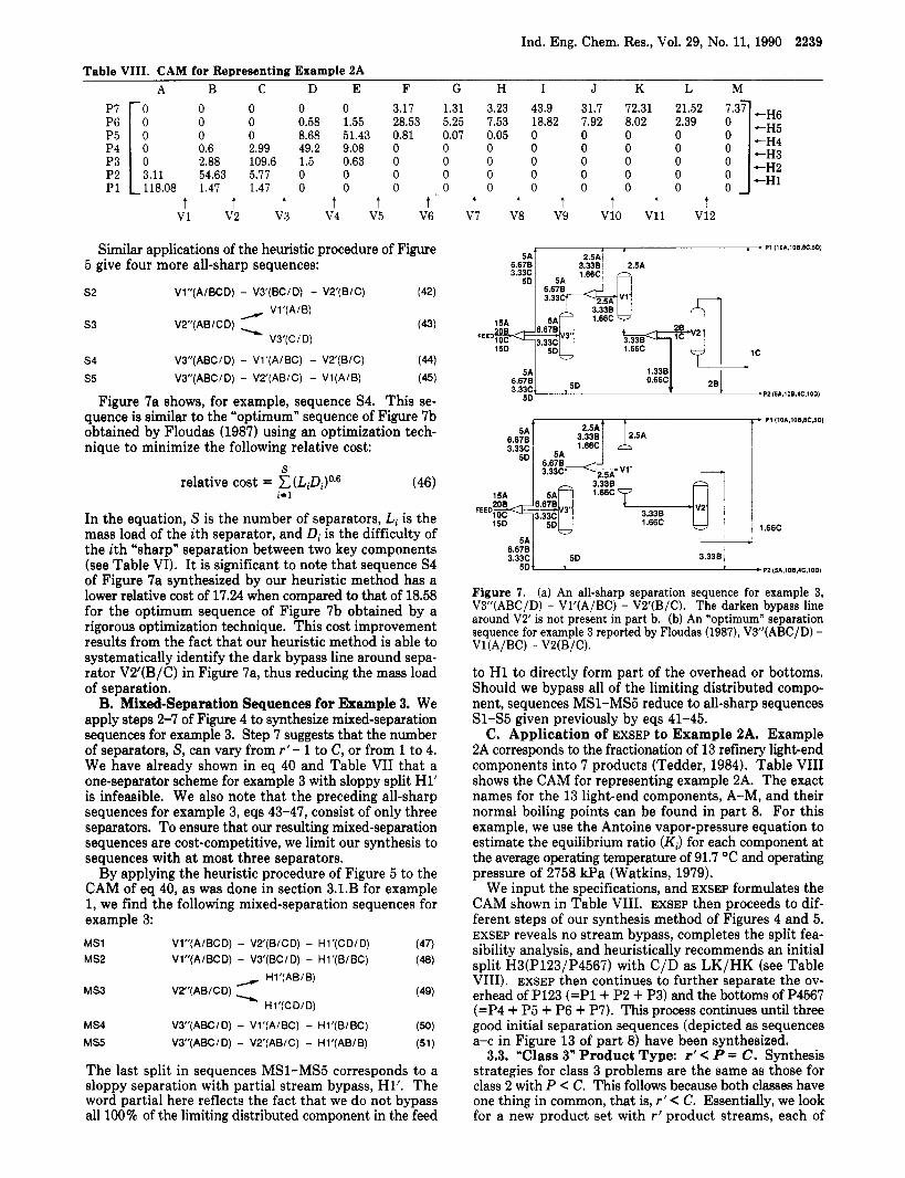
Figure 7a shows, for example, sequence S4. This se- quence is similar to the “optimum” sequence of Figure 7b obtained by Floudas (1987) using an optimization tech- nique to minimize the following relative cost:
S
i=l relative cost = C(LiDi)o.6 (46)
In the equation, S is the number of separators, Li is the mass load of the ith separator, and Di is the difficulty of the ith “sharpw separation between two key components (see Table VI). I t is significant to note that sequence S4 of Figure 7a synthesized by our heuristic method has a lower relative cost of 17.24 when compared to that of 18.58 for the optimum sequence of Figure 7b obtained by a rigorous optimization technique. This cost improvement results from the fact that our heuristic method is able to systematically identify the dark bypass line around sepa- rator VB’(B/C) in Figure 7a, thus reducing the mass load of separation.
B. Mixed-Separation Sequences for Example 3. We apply steps 2-7 of Figure 4 to synthesize mixed-separation sequences for example 3. Step 7 suggests that the number of separators, S, can vary from r’- 1 to C, or from 1 to 4. We have already shown in eq 40 and Table VI1 that a one-separator scheme for example 3 with sloppy split H1’ is infeasible. We also note that the preceding all-sharp sequences for example 3, eqs 43-47, consist of only three separators. To ensure that our resulting mixed-separation sequences are cost-competitive, we limit our synthesis to sequences with at most three separators.
By applying the heuristic procedure of Figure 5 to the CAM of eq 40, as was done in section 3.1.B for example 1, we find the following mixed-separation sequences for example 3:
MS1 Vl”(A/BCD) - VS‘(B/CD) - Hl’(CD/D) (47) MS2 Vl”(A/BCD) - V3’(BC/D) - Hl’(B/BC) (4) - Hl’(AB/B)
H1 ’(CD/ D) MS3 VP‘(AB/CD) - (49)
MS5 VS”(ABCID) - VZ‘(AB/C) - Hl’(AB/B) (51)
MS4 VB”(ABC/D) - Vl’(A/BC) - Hl’(B/BC) (50)
The last split in sequences MS1-MS5 corresponds to a sloppy separation with partial stream bypass, Hl’. The word partial here reflects the fact that we do not bypass all 100% of the limiting distributed component in the feed
t t t t t t V7 V8 V9 v10 V11 v12
1 3 . 3 3 c F
0.66C PZ (5A.lOBCC.lOD)
P1 (lOA,lOB,BC.SD) f
, 1.66C
6.678 3.33c 50 3.338 1
1 50 + P2 (5A,lOB,4C,lOD)
Figure 7. (a) An all-sharp separation sequence for example 3, V3”(ABC/D) - Vl’(A/BC) - VP‘(B/C). The darken bypass line around V2‘ is not present in part b. (b) An “optimum” separation sequence for example 3 reported by Floudas (1987), VI”(ABC/D) -
to H1 to directly form part of the overhead or bottoms. Should we bypass all of the limiting distributed compo- nent, sequences MS1-MS5 reduce to all-sharp sequences Sl-S5 given previously by eqs 41-45.
C. Application of EXSEP to Example 2A. Example 2A corresponds to the fractionation of 13 refinery light-end components into 7 products (Tedder, 1984). Table VI11 shows the CAM for representing example 2A. The exact names for the 13 light-end components, A-M, and their normal boiling points can be found in part 8. For this example, we use the Antoine vapor-pressure equation to estimate the equilibrium ratio (Ki) for each component a t the average operating temperature of 91.7 “C and operating pressure of 2758 kPa (Watkins, 1979).
We input the specifications, and EXSEP formulates the CAM shown in Table VIII. EXSEP then proceeds to dif- ferent steps of our synthesis method of Figures 4 and 5. EXSEP reveals no stream bypass, completes the split fea- sibility analysis, and heuristically recommends an initial split H3(P123/P4567) with C/D as LK/HK (see Table VIII). EXSEP then continues to further separate the ov- erhead of P123 (=P1+ P2 + P3) and the bottoms of P4567 (=P4 + P5 + P6 + P7). This process continues until three good initial separation sequences (depicted as sequences a-c in Figure 13 of part 8) have been synthesized.
3.3. “Class 3” Product Type: r’ < P = C. Synthesis strategies for class 3 problems are the same as those for class 2 with P < C. This follows because both classes have one thing in common, that is, r’ < C. Essentially, we look for a new product set with r’ product streams, each of
Vl(A/BC) - V2(B/C).

2240 Ind. Eng. Chem. Res., Vol. 29, No. 11, 1990
which consists of up to C components. The whole syn- thesis procedure will proceed according to the relative magnitudes of r’ and C, as shown in Figure 4.
3.4. “Class 4” Product Type: C C P . A. “Class 4a” Product Type: r’ = C C P . The synthesis strategy for this product type is identical with that of class 1 with r’ = P = C. The reasoning behind this observation is that the original product streams in class 4a are reduced to a new product set with r’ (or C) product streams made up of C components.
B. ”Class 4b” Product Type: C C r’ = P. For this product type, we first recognize that our synthesis strategy is to consider possible all-sloppy sequences incorporating at most one more separator than competing all-sharp se- quences. Thus, we apply the all-sloppy synthesis method for product sets with r’values being equal to C + 1 (see Figure 4). For product sets with higher r’values, however, we should use only the all-sharp synthesis method.
C. “Class 4c” Product Type: r’ C C C P. Recall that earlier for class 2 product type with P C C, we obtain the relationship r f < C. Therefore, class 4c product type is similar to class 2 product type, and the synthesis schemes for both types should be identical.
3.5. Two-Feed Separation Problems. In this section, we present an example to illustrate how to extend the basic tools and concepts of the preceding sections for synthes- izing initial sequences for two-feed separation problems. Example 4, investigated previously by Mahalec and Mo- tard (1977) and by Floudas (1987), may be represented by the following; CAMS for feeds and products:
(52) In a multiple-feed problem, we need to characterize an all-component-inclusive product with respect to a specific feed. Thus, product P3 is all-component-inclusive with respect to feed F1, and product P2 is all-component-in- clusive with respect to feed F2.
We apply steps 1-4 of Figure 5 and bypass one-half of F1 (that is, 100 mol/h of A and 500 mol/h of B) to P3 and also two-thirds of F2 (that is, 330 mol/h of A, 330 mol/h of B, and 200 mol/h of C) to P2. Equation 52 becomes
Vl’(Fl’,A/B) 1 A B C -
V2‘(F2‘,AB/C) (53) By performing vertical split operation V1 on feed F1’ (to isolate product P3’) and V2 on feed F2‘ (to isolate product P2’), we can easily synthesize the desired product set:
A to P1’
B lo P3‘
AB to P2’
c to P1’
/ V1‘ (Fl‘, AIB) -
(54)
V2’ (F2’, ABIC) = Figure 8 shows the resulting sequence, which represents the optimum sequence in terms of minimizing the mass load of separation (Floudas, 1987).
The solution to example 4 suggests two useful heuristics for multiple-feed separation problems: (1) avoid blending together of initial feeds with different compositions in
330A 3308 ~
2wc ,
170A 5008 3wc 1708
1 ooc
FEED 2 ’e
c q A 1 W A
FEED 1
--PJ(tWA>WOB)
Figure 8. An all-sharp separation sequence obtained for a multi- ple-feed problem, example 4.
order to reduce the mass load of separation and (2) perform sharp component splits on initial feeds early so as to isolate components that immediately form products or parts of products. Further work is needed, however, to incorporate sloppy splits into the synthesis scheme for multiple-feed separation problems.
4. Conclusions The development of simple methods for the systematic
design of multicomponent separation systems with sloppy product streams is one of the most challenging problems in process design research over the past 20 years. Such separation systems find much use in the fractionations of refinery light ends and saturate gas components and in recycled reactor systems for reactant recovery and by- product separation, where it is often unnecessary to utilize the generally more expensive, sharp separation systems with high component recoveries.
In this paper, we have presented a unifying method for the synthesis of good initial flowsheets for multicomponent separations with sloppy product streams. These flowsheets utilize a minimum number or a nearly minimum number of three types of equally good separators, namely, all-sharp, all-sloppy, and mixed-separation (Le., both sharp and sloppy) sequences. To synthesize these competing se- quences, we have introduced some simple and flexible tools for representing a given separation problem, called the component assignment matrix, and for analyzing the technical feasibility and ranking the relative ease of dif- ferent separation tasks, called the separation specification table. On the basis of the rank relationship of the CAM, the number of components, and the number of products, we have proposed a unifying classification of all multi- component separation-sequencing problems into four classes and have suggested proper approaches to solving each class of synthesis problems. We have particularly demonstrated the simplicity and effectiveness of applying six rank-ordered heuristics together with CAM, SST, and stream bypass to a number of industrial separation prob- lems. The resulting separation sequences represent good initial flowsheets for further heat integration and separator optimization.
Of particular significance is that our synthesis method can be applied by hand calculations and can be readily used by a practicing engineer. I t has also been imple- mented as an expert system called EXSEP using PROLOG on a personal computer. Operating interactively with a design engineer, EXSEP can easily out-pace the engineer’s

Ind. Eng. Chem. Res., Vol. 29, No. 11, 1990 2241
separator to directly form parts of both overhead and bottoms
Greek Le t t e r s LYLK,HK = relative volatility of LK with respect to that of HK Symbol h = AT (normal boiling-point difference, “C) or 100 (a - 1)
Literature Cited Aggarwal, A.; Floudas, C. A. Synthesis of General Distillation Se-
quences-Nonsharp Separations. AIChE National Meeting, Houston, TX, April, 1989; Paper 32d.
Bamapoulos, G.; Nath, R.; Motard, R. L. Heuristic Synthesis of Nonsharp Separation Sequences. AIChE J . 1988, 34, 763-780.
Cheng, S. H.; Liu, Y. A. Studies in Chemical Proces Design and Synthesis. 8. A Simple Heuristic Method for the Synthesis of Initial Sequences for Sloppy Multicomponent Separations. Ind. Eng. Chem. Res. 1988,27, 2304-2322.
Floudas, C. A. Separation Synthesis of Multicomponent Feed Streams into Multicomponent Product Streams. AIChE J . 1987, 33, 540-551.
Floudas, C. A.; Anastasiadis, S. H. Synthesis of General Distillation Sequences with Several Multicomponent Feeds and Products. Chem. Eng. Sci. 1988,43, 2407-2419.
Henley, E. J.; Seader, J. D. Equilibrium-Stage Separation Opera- tions in Chemical Engineering; Wiley: New York, 1981; pp
Liu, Y. A. Process Synthesis: Some Simple and Practical Develop- ments. In Recent Deoelopments in Chemical Process and Plant Design; Liu, Y. A., McGee, H. A., Jr., Epperly, W. R., Eds.; Wiley: New York, 1987; pp 147-260.
Mahalec, V.; Motard, R. L. Procedures for the Initial Design of Chemical Processing Systems. Comput. Chem. Eng. 1977, 1, 57-68.
Muraki, M.; Hayakawa, T. Separation Process Synthesis for Multi- component Products. J . Chem. Eng. Jpn. 1984, 17, 533-538.
Muraki, M.; Hayakawa, T. Multicomponent Product Separation Process Synthesis with Separation Sharpness. J . Chem. Eng. Jpn.
Muraki, M.; Hayakawa, T. Synthesis of a Multicomponent Multi- product Separation Process with Nonsharp Separators. Chem. Eng. Sci. 1988, 43, 259-268.
Muraki, M.; Kataoka, K.; Hayakawa, T. Evolutionary Synthesis of a Multicomponent Multiproduct Separation Process. Chem. Eng.
Nath, R. Studies in the Synthesis of Separation Processes. Ph.D. Dissertation, University of Houston, Houston, TX, 1977.
Tedder, D. W. The Synthesis of Optimal Gas Saturates Separation System. AIChE Annual Meeting, San Francisco, CA, 1984.
Watkins, R. N. Petroleum Refinery Distillation, 2nd ed.; Gulf Houston, TX, 1979; p 159.
Westerberg, A. W. The Synthesis of Distillation-Based Separation Systems. Comput. Chem. Eng. 1985, 9,421-429.
Received for review February 9, 1990 Revised manuscript received June 19, 1990
Accepted July 1, 1990
527-555.
1987, 20, 195-198.
Sei. 1986,41, 1843-1851.
ability to assimilate the necessary design information and to synthesize good separation flowsheets.
Nomenclature bi = ith component molar flow rate in the bottoms, mol/h;
or in normalized situation, ith component recovery fraction in the bottoms, dimensionless
B = molar flow rate of the bottoms, mol/h C = number of components CAM = component assignment matrix CAM(Hi,btm), CAM(Hi,ovhd) = CAM for representing the
bottoms and overhead resulting from horizontal product split Hi, respectively
CAM(Vj,btm), CAM(Vj,ovhd) = CAM for representing the bottoms and overhead resulting from vertical component split Vj, respectively
CES = coefficient of ease of separation defined in eq 3 di = ith component molar flow rate in the overhead, mol/h;
or in normalized situation, ith component recovery fraction in the overhead, dimensionless
D = molar flow rate of the overhead, mol/h f = D/B or B/D, whichever is smaller than or equal to unity,
dimensionless f i j = elements of the component assignment matrix repre-
senting the flow rate of the jth component in the ith product (i = 1, 2, ..., P; j = 1, 2, ..., C)
Hi = horizontal product split i (i = 1, 2, ..., P) HHK1-3 = heavier-than-heavy-key or heavy components 1-3
whose volatilities are in a descending order HK = heavy-key component Ki = vapor-liquid equilibrium ratio of component i, dimen-
sionless LK = light-key component LLK1-3 = lighter-than-light-key or light components 1-3
whose volatilities are in an ascending order Nmin = minimum number of theoretical stages P = number of product streams, or column pressure, Pa r = rank of the component assignment matrix r’ = pseudorank of the component assignment matrix R D = operating reflux ratio RD,min = minimum reflux ratio Smin = apparent minimum number of separators, eq 1 SST = separation specification table Vj = vertical component split j ( j = 1, 2, ..., C)
Superscr ip ts ’ = prime, indicates the CAM resulting from, or the horizontal
product split Hi (vertical component split Vj) made after, bypassing a portion of the feed around the separator to directly form part of an overhead or a bottoms
” = double prime, indicates the CAM resulting from, or the horizontal product split Hi (vertical component split Vj) made after, bypassing two portions of the feed around the