project 1: chemical process alternatives for radioactive waste year 6 ptp - proj 1 - hlw -...
TRANSCRIPT

PROJECT TECHNICAL PLAN
Project 1: Chemical Process Alternatives for Radioactive Waste
Performance Period: August 29, 2015 to August 28, 2016
Date submitted:
October 5, 2015
Principal Investigator:
Leonel E. Lagos, Ph.D., PMP® Applied Research Center
Florida International University 10555 West Flagler Street, EC2100
Miami, FL 33174
Submitted to:
U.S. Department of Energy Program Services Division, ME-643.1
1000 Independence Avenue, SW Washington, D.C. 20585
Cooperative Agreement DE-EM0000598

1 Applied Research Center – FIU Year 6 Project Technical Plan Chemical Process Alternatives for Radioactive Waste
INTRODUCTION
The U.S. DOE Hanford Site has the largest number of high-level waste (HLW) storage tanks and
the largest volume of HLW in the United States. The safe storage, retrieval, treatment, and
disposal of approximately 53 million gallons of highly toxic, high-level radioactive waste stored
in Hanford’s 177 underground tanks are a national priority. Retrieval and treatment of waste
from these tanks pose a considerable challenge.
Florida International University has been
conducting research on several promising
alternative processes and technologies that can
be applied to address several technology gaps
in the current waste retrieval and conditioning
plans. Specifically, FIU has been involved in:
modeling and analysis of multiphase flows
pertaining to waste feed mixing processes,
evaluation of alternative HLW instrumentation
for in-tank applications and the development of
technologies to assist in the inspection of tank
bottoms at Hanford.
TECHNOLOGY NEEDS
The implementation of advanced technologies
to address challenges faced with baseline plans
for HLW operations is of great interest to the
Hanford Site. Specifically, the use of field-
deployable or in-tank technologies, as well as
advanced computational methods can improve
the retrieval, transport and conditioning
processes of HLW. FIU has worked with site
personnel to identify three focus areas related to technology and process improvement needs that
can benefit from FIU’s core expertise in areas related to HLW operations.
Focus Area 1: Robust computational fluid dynamics capability to accurately and effectively
model complex, multi-phase, HLW processes
The mixing performance of pulse-jet mixers (PJM) depends on the geometry of the vessel,
number and orientation of the PJMs, slurry rheology, cycle characteristics and other variables
which makes the experimental evaluation a big challenge due to the large number of variables
and high cost associated with building and testing the mixing process in the tanks.
Computational fluid dynamics (CFD) predictions using computer simulations of the multiphase
flow physics by solving the governing equations for the gas-solid multiphase flow under
turbulent flow conditions can be used to aid in the design estimations and performance scaling
DOE EM HQ Contacts:
John DeGregory, EM-13, FIU Liaison, Office of D&D & Facility Engineering Gary Peterson EM-21, Tank Waste Management
Site Contacts:
Ruben Mendoza, Washington River Protection Solutions Terry Sams, Washington River Protection Solutions Dennis Washenfelder, Washington River Protection Solutions Joel Peltier, Bechtel Chris Gunther, National Energy Technology Laboratory Dawn Wellman, Pacific Northwest National Laboratory FIU ARC Contacts:
Dwayne McDaniel, Ph.D., P.E. Project Manager, Sr. Research Scientist (305) 348-6554 E-mail: [email protected]
Leonel Lagos, Ph.D. PMP® Principal Investigator, Director of Research (305) 348-1810, E-mail: lagosl@ fiu.edu
Applied Research Center Florida International University 10555 W. Flagler St., Suite 2100 Miami, FL 33174

2 Applied Research Center – FIU Year 6 Project Technical Plan Chemical Process Alternatives for Radioactive Waste
calculations for tanks where the PJMs will be used for the next 40 years in the vitrification
process of the nuclear waste in the Waste Treatment and Immobilization Plant at Hanford.
FIU has partnered with the Office of River Protection, Bechtel Corporation and the National
Energy Technology Laboratory to build CFD models that have the correct physical models,
boundary conditions, and PDE solvers that will result in accurate simulations that can be used for
various waste mixing scenarios that can be created virtually on large computer clusters to obtain
relatively quick answers for the design and optimization of PJM operations. For this purpose,
Star-CCM+ software has been identified as the framework where the CFD models will be
developed.
Focus Area 2: Technology development and innovative instrumentation evaluation for HLW
tanks
Hanford engineers have a need to develop technologies that can provide inspection and possibly
repair capability for their double-shell tanks (DSTs). Small amounts of waste have been found in
the annulus of AY-102, prompting the need for developing inspection tools that can identify the
cause and exact location of the leak. The inspection tools will have to navigate through complex
cooling channels of the DST refractory pad or through air supply lines and provide visual
feedback of the tank bottom. FIU has developed initial prototype tools and is currently working
with site engineers to determine optimal and cost efficient ways to conduct full scale mock-up
testing.
Additionally, FIU has efforts supporting Hanford’s need to evaluate instrumentation and sensors
that may improve personnel and environmental safety. These efforts focus on utilizing
commercial off-the-shelf-technologies that assist in providing data that can improve the
operational processes in the Hanford tanks. Examples include utilizing FIU’s solid-liquid
interface monitor (SLIM) to aid in identifying precursors to gas release events that could
potentially allow for lower flammability limits to be exceeded. FIU is also investigating the use
of infrared sensors for the monitoring of internal wall temperatures of the DSTs. Use of these
sensors can aid in identifying whether the tank operating parameters are within prescribed limits.
Focus Area 3: Structural integrity analysis for HLW pipelines
Understanding the current and future status of the structural integrity of the waste transfer system
at Hanford is of paramount importance to DOE, engineering contractors and the local
community. The tank contractor, Washington River Protection Solutions, LLC (WRPS), has
implemented a Fitness-for-Service program that focuses on evaluating the structural integrity of
waste transfer system components including primary piping, encasements, and jumpers when
they are removed for disposal. FIU is assisting site engineers with evaluating sensors that can
provide thickness data on transfer system components that are still operating and provide data in
real time. The objective is to provide WRPS with a means to measure the remaining useful life of
the components and incorporate the data into future design plans.
Additionally, support is needed for Hanford engineers with regard to understanding the integrity
of non-metallic components in the HLW transfer system. There are four primary stressors that
can affect the performance of non-metallic components. These include temperature, pressure,
radiation, chemistry. In general, it has been well established how the non-metallic components

3 Applied Research Center – FIU Year 6 Project Technical Plan Chemical Process Alternatives for Radioactive Waste
respond to the stressors individually, but the cumulative effect is less understood. FIU will assist
site engineers with understanding how the combined effect of three of the four stressors (not
including radiation) can degrade the performance of non-metallic components via bench scale
testing.
TASK DESCRIPTIONS
Based on the aforementioned technology and research needs, three tasks (with a total of six
subtasks) have been identified for the next performance period. FIU will work with Hanford Site
personnel, national laboratory contacts, and collaborators from industry and academia to identify
shortcomings of the baseline approach and past research efforts. This knowledge will be
incorporated into the planning and execution of these tasks detailed below.
Note: Task numbers are not continuous because task numbers have been assigned
chronologically over the past 5 years and several tasks have been completed.

4 Applied Research Center – FIU Year 6 Project Technical Plan Chemical Process Alternatives for Radioactive Waste
TASK 17 – ADVANCED TOPICS FOR MIXING PROCESSES
Subtask 17.1 – Computational Fluid Dynamics Modeling of HLW Processes in Waste Tanks
This task will use the knowledge acquired at FIU on multiphase flow modeling to build a CFD
computer program in order to obtain simulations at the engineering-scale with appropriate
physics captured for the analysis and optimization of PJM mixing performance. Focus will be
given to turbulent fluid flow in nuclear waste tanks that exhibit non-Newtonian fluid
characteristics.
Objective
The objective of this task is to provide the sites with mathematical modeling, validation, and
testing of computer programs to support critical issues related to HLW retrieval and processing.
FIU engineers work directly with site engineers to plan, execute, and analyze the results of
applied research and development. Specific subtasks include:
Develop a CFD model based on the Star-CCM+ framework to simulate the turbulent jet-flow
in non-Newtonian fluids that show Bingham plastic behavior. The model will provide
improved efficiency over standard modeling techniques but still capture the salient features
of the fluid flow.
Execute verification and validation analysis for the uncertainty prediction in the results of
Star-CCM+ software for benchmark cases of multiphase flow.
Benefits
The proposed activities under this subtask at FIU-ARC will provide the necessary data and
computational tools for the engineering staff at the sites to use in order to predict various
scenarios that can occur during operations at DOE sites that involve multiphase flows involving
waste sludge that acts as Bingham plastic. Successful completion of the subtasks will result in
time and cost savings and risk minimization, leading to increased environmental safety in the
operations at the DOE sites as well as design and operation of future waste treatment tanks to be
placed in black cells at the WTP site that will utilize the PJM mixing technique.

5 Applied Research Center – FIU Year 6 Project Technical Plan Chemical Process Alternatives for Radioactive Waste
TASK 18 – TECHNOLOGY DEVELOPMENT AND INSTRUMENTATION EVALUATION
Subtask 18.1 – Evaluation of FIU’s Solid-Liquid Interface Monitor for Estimating the Onset of Deep Sludge Gas Release Events (New)
In recent years, Hanford engineers have been focusing on increasing tank space in DSTs to
mitigate issues related to the aging of SSTs. One of the major concerns associated with these
transfers is the potential release of flammable gas. This can occur when the sludge levels are
exceedingly high in the DSTs and is referred to as a deep sludge gas release event (DSGRE).
During the mixing processes prior to transfer, gas could be released. The tank farm contractors
are required to maintain various tank conditions including keeping the flammability level in the
tank head space below a specified level (lower-flammability limit – LFL). In the process of
transporting the waste and the formation of deep sludge levels, gas within the sludge may be
released and the LFL in the head space could exceed prescribed LFLs.
To mitigate these types of events, engineers at Hanford have conducted a number of research
activities ranging from modeling multiphase systems comprised of the gas and sludge to
experimental work involving the use of tall columns to evaluate retention properties of sludge. In
this subtask, FIU will investigate the use of our SONAR system to provide images of sludge
surfaces and to determine if the sonar can provide topographical information that may suggest a
DSGRE is about to occur.
Objective
The objective is this subtask is to evaluate FIU’s solid-liquid interface monitor (SLIM) for its
ability to image sludge surfaces and determine whether a DSGRE is about to occur. Pilot-scale
testing will be conducted to evaluate SLIM’s resolution and its ability to identify topographical
changes in a sludge surface due to the formation of a gas bubble. Efforts will also focus on how
the sludge shear stress may affect the gas bubble size and ultimately the ability of SLIM to detect
DSGREs.
Benefits
As the tanks at Hanford continue to age, there is a need to maximize the current available space
in the DSTs. This research would serve as a tool to assist in understanding the relationship
between sludge depth, sludge shear stress and the potential for DSGREs. This research will
provide engineers at Hanford with information that could aid in maximizing tank space as well
as providing a means to reduce risk to personnel by predicting the onset of gas release events that
could increase gas in the head space to a level beyond the LFL.

6 Applied Research Center – FIU Year 6 Project Technical Plan Chemical Process Alternatives for Radioactive Waste
Subtask 18.2 – Development of Inspection Tools for DST Primary Tanks
As part of the Hanford DST integrity program review, engineers at Hanford are investigating
robotic technologies for the evaluation of Tank 241-AY-102. The technologies are intended to
provide video feedback of the tank refractory and base pad so that an assessment can be made
regarding the structural integrity of the tank bottom. There are three paths of access: 1) refractory
air slots though the annulus, 2) 4-in annulus air supply pipe to central plenum, and 3) 6-in leak
detection pit drain from the central sump. In previous years, engineers at Hanford have requested
information from industry regarding their capability to inspect the tank insulating refractory pad
and provide visual feedback as well as potential for conducting repairs.
Objective
The objective of this task is to develop inspection tools that can provide visual feedback of DST
bottoms from within the insulation refractory pads and through the air supply lines. FIU
engineers will continue to work directly with site engineers to develop and test the alternative
designs. Specific subtasks include:
Develop and improve on design concepts that will allow for the navigation of a remotely
controlled device through the refractory pad channels of DST tanks in the AY Farm and
provide visual feedback. A prototype of the inspection tool will be evaluated in a mock-up
test bed constructed at FIU.
Develop and improve on design concepts that will allow for the navigation of a crawler
inspection tool that can navigate through a 3-in and 4-in air supply pipe that leads to the
central plenum of the Hanford tanks in the AY Farm. A prototype of the inspection tool will
be evaluated in a mock-up test bed constructed at FIU.
Benefits
The proposed subtask will provide alternative solutions for monitoring the structural integrity of
the bottoms of the DSTs. Tools developed in this subtask will allow for the detection of potential
leaks, allowing site engineers to obtain the necessary information that is needed to generate
viable approaches for repair.
Subtask 18.3 – Investigation using an infrared temperature sensor to determine the inside wall temperature of DSTs (New)
As part of the Hanford DST integrity program, engineers at Hanford are interested in
understanding the temperatures inside the primary tanks and to safeguard against exceeding
specified limits (OSD-T-151-00007). These limits are set to ensure that the tanks are not exposed
to conditions that could lead to corrosion of the tank walls. Previously, analysis was conducted to
determine the viability of using an infrared (IR) temperature sensor within the annulus space to
estimate the temperature of the inside wall of the tank. The analysis suggested that variations due
to heat loss would be minimal and reasonable estimates using the sensor within the annulus is
viable.
7 Applied Research Center – FIU Year 6 Project Technical Plan Chemical Process Alternatives for Radioactive Waste
Objective
The objective of this task is to evaluate the ability of IR sensors to detect inner tank wall
temperatures via bench scale testing. Specific subtasks include:
Working with Hanford engineers to develop a test plan that can assess the viability of using
an IR sensor for estimating the inner wall temperature of the tank.
Executing the test plan and providing insight to Hanford engineers regarding the expectations
and limitations of using the IR sensor for this purpose.
Benefits
Tank integrity at the Hanford tank farms is of critical importance to engineers at the site. Recent
leaks found in AY-102 have led to a number of issues that need to be evaluated to potentially
understand the source of the leak. Issues include maintaining the tank at specified temperature
limits. The proposed subtask will assist engineers with obtaining additional temperature data
within the tank and understanding the uniformity of the temperature near the tank walls. This
information will aid in the evaluation of various theories of the cause of the tank leak and
provides a means to ensure that tank temperatures stay within specified parameters.
8 Applied Research Center – FIU Year 6 Project Technical Plan Chemical Process Alternatives for Radioactive Waste
TASK 19 – PIPELINE INTEGRITY AND ANALYSIS
Subtask 19.1 – Pipeline Corrosion and Erosion Evaluation
The United States Department of Energy Hanford Site Tank Farm has implemented a Fitness-
for-Service (FFS) program for the Waste Transfer System. The FFS program, based on API-579-
1/ASME FFS-1, examines structural parameters of the waste transfer systems in order to develop
erosion/corrosion rates for relevant system components. The FFS information is acquired from
opportunistic evaluations of pipelines that have been removed from service. FIU-ARC engineers
will work closely with key Hanford HLW personnel, on the FFS program, delivering solutions
for sensor evaluations, conducting bench scale testing followed by data acquisition and analysis
for corrosion and erosion assessment.
Objective
The objective of this task is to evaluate potential sensors for obtaining thickness measurements
of HLW pipeline components. Specific applications include straight sections, elbows and other
fittings used in jumper pits, evaporators, and valve boxes. FIU will assess the use of various
ultrasonic systems that are either commercially available or used previously at Hanford and
select the most promising systems for further evaluation.
Benefits
The proposed task will provide information that will assist engineers with understanding the
failure potential of HLW transfer components due to corrosion and erosion. This information can
assist in determining if and when lines need to be removed, saving time and resources on the
unneeded excavation of transfer lines. This information will also assist engineers with designing
new transfer systems by establishing more detailed/accurate guidelines governing the life
expectancy of the transfer system and its components.
Subtask 19.2 – Evaluation of Nonmetallic Components in the Waste Transfer System
Nonmetallic materials are used in the Hanford Site Tank Farm waste transfer system. These
materials include the inner primary hoses in the hose-in-hose transfer lines (HIHTLs), Teflon®
gaskets, ethylene propylene diene monomer (EPDM) O-rings, and other nonmetallic materials.
These nonmetallic materials are exposed to β and γ irradiation, caustic solutions as well as high
temperatures and pressure stressors. How the nonmetallic components react to each of these
stressors individually has been well established. However, simultaneous exposure of these
stressors has not been evaluated and is of great concern to Hanford Site engineers. FIU-ARC
engineers have worked closely with key Hanford HLW personnel to develop an experimental
test plan to determine how these nonmetallic components react to various simultaneous stressor
exposures.

9 Applied Research Center – FIU Year 6 Project Technical Plan Chemical Process Alternatives for Radioactive Waste
Objective
The objective of this task is to provide the Hanford Site with data obtained from experimental
testing of the hose-in-hose transfer lines, Teflon® gaskets, EPDM O-rings, and other nonmetallic
components used in their tank farm waste transfer system under simultaneous stressor exposures.
Due to experimental testing location limitations, no radiation exposure testing will be conducted.
The stressor exposure experiments will be limited to various combinations of simultaneous
stressor exposure of caustic solutions, high temperatures and high pressure stressors. Evaluation
of baseline materials will be conducted and compared with materials that have been conditioned
with the various stressors.
Benefits
This task will provide information that will assist engineers with understanding how the
nonmetallic components of the tank farm waste transfer system react to simultaneous stressor
exposures of caustic solutions, high temperatures and high pressure. This will help in
determining the service life of the waste transfer system parts that contain nonmetallic
components. This information will also assist engineers with designing new transfer systems by
establishing more detailed/accurate guidelines governing the life expectancy of the transfer
system parts.

10 Applied Research Center – FIU Year 6 Project Technical Plan Chemical Process Alternatives for Radioactive Waste
FIU YEAR 5 TASK EXECUTION PLANS
Overall Project Management Task
This task will focus on the control and monitoring components of the project. This task will
perform quarterly report development, client interaction, progress tracking, and the development
of the final report.
Subtask 17.1.1 – Computational fluid dynamics modeling of jet penetration in non-Newtonian fluids
The capability of the commercial CFD code, Star-CCM+, needs to be improved in simulating the
mixing effect created by high velocity jets in non-Newtonian fluids produced by the pulse-jet
mixers in large storage tanks with complex geometries, in order to accurately predict the mixing
behavior of the nuclear sludge. This is especially important for modeling the flow of Bingham
plastics since the waste at the Hanford Site is of that type.
The existing Herschel-Bulkley model in the Star-CCM+ code which combines a Bingham fluid
with a power-law model is unable to represent the viscoplastic behavior of the sludge properly
under turbulent flow conditions when the computational model is unable to resolve the small
scale changes in the fluid using the Reynolds-average Navier-Stokes (RANS) modeling
approach. This will be corrected by providing additional information for the shear rates obtained
with Direct Numerical Simulation (DNS) methods and correcting the viscosity calculation in the
RANS approach. Three dimensional pipe flow under laminar, transitional and turbulence flow
conditions will be simulated to verify the modification to the definition of viscosity. Results will
be compared against DNS and experimental results.
Subtask 17.1.2 – Computational fluid dynamics validation of jet impingement correlations
Subtask 17.1.2 is one of two new subtasks (the other is subtask 18.3.1) added to the PTP that
were not described in the Renewal Application. These two new subtasks will be performed using
the level of effort originally planned for Task 20, Innovative Nuclear Separations of High Level
Radioactive Waste, which was dropped from the planned scope of work for FIU Year 6. The two
new subtasks were determined to be a higher priority for the Hanford Site.
Currently, two correlations from a jet impingement experiment developed by Poreh et al. (1967)
are being extensively used in the validation of lightly loaded pulse jet mixing (PJM) vessels.
Criticism arises in the application of such correlations due to geometric differences between the
experiment from which the two correlations were derived and the PJMs. The correlations dictate
whether criticality within a vessel will be reached; therefore, it is imperative to properly validate
their accuracy.
Previously, FIU has used StarCCM+ to perform RANS modeling in order to successfully
replicate Poreh's experimental results. FIU has also similarly modeled Poreh's experiment with a

11 Applied Research Center – FIU Year 6 Project Technical Plan Chemical Process Alternatives for Radioactive Waste
slight geometric difference which more closely resembles the PJMs. We will continue this effort
by analyzing and confirming the two correlations in the simulation. Furthermore, geometrical
changes to Poreh's experiment that will approach the PJM's vessels will be simulated and
analyzed in succession until full geometric similarity is reached. The efforts of this task will help
to ascertain the accuracy of Poreh’s correlations as applied to the lightly loaded PJMs vessels.
Subtask 18.1.1 – Bench scale testing of SLIM to detect potential DSGREs
This subtask will focus on the testing of the SLIM sonar to image sludge surfaces when the
sludge has gas bubble(s) incorporated into it. The intent is to determine if SLIM can be used as a
tool that can identify sludge surface changes that precede DSGREs. With the assistance of
Hanford engineers, FIU will develop a test plan and conduct bench scale tests to assess the
viability of SLIM for this use. A 3-5 foot diameter tank will be used to contain sludge simulant
made from Kaolin clay. Various shear strengths of sludge will be manufactured and various
bubble sizes will be used to create undulations on the sludge surface. Images will be taken using
SLIM and changes in the surface will be correlated with sludge shear strength and gas bubble
volume. Specific details of the bench scale tests will be discussed and finalized with Hanford
engineers prior to testing.
Subtask 18.2.1 – Finalize design and complete prototype for tank floor inspection through the refractory pad
During the previous year, FIU has developed a prototype of an inspection tool to investigate DST
floors via air channels in the refractory pads. This year, the prototype will be subject to further
improvement and modifications. Efforts will focus on determining operational voltage levels
associated with the recently incorporated gear motors. Additionally, the tether housing for the
power and camera lines will be selected to minimize the drag force. Experiments will be
conducted to quantify the overall tether drag and determine the efficiency of the design to
navigate through the first 17 feet of the air channels. Additional testing will include the unit’s
ability to make turns and pull the tether while carrying potential loads associated with future
inspection equipment. After the design and fabrication have been finalized, full scale mock-up
testing will be conducted.
Subtask 18.2.2 – Develop full scale mock-up test bed for inspection through the refractory pad
A mock-up of the AY-102 tank refractory air channels will be manufactured at FIU. The
intention is to provide a platform for conducting cold tests prior to deployment at Hanford. The
mock-up will be designed according to specifications provided by site engineers at Hanford.
Extra care will be taken to assure a high correlation between the mock-up and potential
inspections in the AY Tank Farm. Finally, the ability of the inspection tool to carry out
operations similar to those at the AY Tank Farm will be evaluated using the full scale test bed.
Subtask 18.2.3 – Finalize design and complete prototype for tank floor inspection through the air supply line
12 Applied Research Center – FIU Year 6 Project Technical Plan Chemical Process Alternatives for Radioactive Waste
In the previous year, a novel functional pneumatic crawler was fully designed, built, assembled,
and preliminarily tested. In the upcoming year, FIU will improve and finalize the design of the
peristaltic inspection tool which includes:
a) Improved gripper design - A stronger grip is an essential improvement in the existing
design. The redesign of the grippers will focus on evaluating other types of locking
mechanisms and the selection of rubber materials with superior coefficients of friction.
The use of radiation hardened electric actuators will also be considered.
b) Tether design - A lighter tether is another essential improvement in the existing design.
The use of micro pneumatic control valves, embedded in the crawler, may reduce the
number of pneumatic supply lines in the tether from 8 to 1.
c) Load feedback - The addition of a small load cell will provide information regarding how
the tether load cell varies as a function of line geometry. Essentially, the load cell would
provide force feedback to the tether drag and indicate whether additional modules need to
be incorporated into the design.
d) Instrumentation modules - Additional modules that include instrumentation will be
investigated. The extra modules could provide feedback for valuable parameters, such as
temperature, pressure, humidity, slope and radiation levels.
The final design will be tested via bench scale tests that simulate several operational conditions
and pipeline configurations. The durability of each component and module will be cyclically
tested under loading. Final design modifications will be incorporated as needed. Testing will also
include retrieval tests, which will demonstrate the safe removal of the tool in case of failure.
Subtask 18.2.4 – Develop full scale mock-up test bed for inspection through the air supply line
A mock-up of the AY-102 tank ventilation header will be manufactured at FIU. The intention is
to provide a platform for conducting cold tests prior to deployment at Hanford. The mock-up will
be designed according to specifications provided by site engineers at Hanford. Extra care will be
taken to assure a high correlation between the mock-up and potential inspections in the AY Tank
Farm. Finally, the ability of the inspection tool to carry out operations similar to those at the AY
Tank Farm will be evaluated using the full scale test bed.
Subtask 18.3.1 – Investigation using an infrared temperature sensor to determine the inside wall temperature of a DST
Subtask 18.3.1 is one of two new subtasks (the other is subtask 17.1.2) added to the PTP that
were not described in the Renewal Application. These two new subtasks will be performed using
the level of effort originally planned for Task 20, Innovative Nuclear Separations of High Level
Radioactive Waste, which was dropped from the planned scope of work for FIU Year 6. The two
new subtasks were determined to be a higher priority for the Hanford Site.
In this subtask, FIU will work with Hanford engineers to develop a test plan for evaluating an IR
temperature sensor to measure the inside thickness of a tank wall. A bench scale mock-up of a
tank will be constructed and a space emulating the annulus will be developed. Hanford engineers
will also assist in the selection of the specific sensor/sensors that will be evaluated. It is
anticipated that the tank will house water that is set to various temperature levels. The tank wall
13 Applied Research Center – FIU Year 6 Project Technical Plan Chemical Process Alternatives for Radioactive Waste
will also have the potential to be varied in terms of thickness. The sensor will be held at variable
distances from the outer tank wall to assess how the measurements change as a function of
location as well as tank temperature and wall thickness. The space representing the annulus
space will also be controlled and may be introduced as a variable depending on the initial results.
Subtask 19.1.1 – Evaluation of alternate UT sensors for erosion and corrosion analysis
In the previous year, FIU worked with Hanford site engineers to evaluate the use of various
couplants for an ultrasonic transducer system to measure thickness of pipes and fittings in real-
time within valve boxes. Based on the constraints of the problem, we focused on evaluating dry
couplants with a standard UT sensor. The results showed that the UT sensor selected for
evaluation was not compatible with the dry couplants, in terms of obtaining consistent data.
Additionally, previous efforts by WRPS demonstrated fallacies in other thickness measuring
systems that included PipeWrap in which thumbnail transducers were imbedded in a polymer
wrap. Issues arose due to variable tightening of the wrap which led to inconsistent measurements
or even failed transducers. This year, FIU will evaluate alternate methods for utilizing/installing
the PipeWrap system as well as investigate similar systems that do not have problems related to
couplants. After the review, exemplar sensor systems will be procured from the sites or from
vendors and bench scale tests will be conducted. We will work with Hanford engineers to
understand the limitations of each system and ultimately determine which system has the
potential for use at the site. The bench scale tests will focus on measurements for elbows and
other fitting and will likely require alternate installation procedures or modification to the
systems that allow for reliable installation methods.
Subtask 19.2.1 – Experimental test loop setup for non-metallic aging
This subtask will involve acquiring all the components needed to fabricate the test loop as well
as the material for the test specimens. Currently, FIU has ordered and is waiting for the delivery
of the inner hose-in-hose transfer line (HIHTL) specimens from Riverbend Inc. Additionally;
FIU is working with Hanford site personnel to determine the optimal fittings for testing the
EPDM O-rings and gaskets. Once the HIHTL specimens have been received, and the fittings
required has been determined, the test loop will be completed.
Subtask 19.2.2 – Baseline experimental testing of non-metallic materials
This subtask will focus on determining the baseline properties for both EPDM coupon samples
and the EPDM components. The EPDM coupon samples will have their material properties
evaluated as per ASTM standards prior to any exposure. Table 1 provides a list of the tests that
will be conducted to provide an understanding of the material properties prior to aging. All
coupons will also be measured to assure they meet baseline ASTM property standards. In
addition, to limit manufacturing variability, all samples will be derived from the same lot.

14 Applied Research Center – FIU Year 6 Project Technical Plan Chemical Process Alternatives for Radioactive Waste
Table 1. EPDM Coupon Sample Tests
Test 1 Dimension change (ASTM 543)
Test 2 Specific gravity and mass change (ASTM
D792, ASTM 543)
Test 3 Tensile strength (ASTM D412)
Test 4 Compression stress relaxation (ASTM
D6147)
Test 5 Ultimate elongation (ASTM D412)
Test 6 Hardness measurements (ASTM 2240)
Additionally, the EPDM components (HIHTLs, O-rings, gaskets) will be tested prior to aging via
leak and hose burst tests. These components will be evaluated in an in-service configuration as
per ASTM D380-94 and ASTM F237-05.
Subtask 19.2.3 – Coupon and component aging
This subtask will involve the aging of the HIHTLs, EPDM gaskets and O-rings used in the
Hanford tank farm waste transfer system under simultaneous stressor exposures. The stressor
exposure experiments will consist of various combinations of simultaneous stressor exposure
including caustic solutions and elevated temperatures. Material coupon specimens as well as
components in-service configurations will be exposed to a combination of simultaneous
stressors. The in-service configuration aging experimental setup will consist of 3 independent
pumping loops with three manifold sections on each loop. Each of the 3 loops will be run at a
different temperature (70oF, 130oF and 180oF). Each manifold section can hold up to three test
samples and be used for a corresponding exposure time of 60, 180 and 360 days. Three samples
of the EPDM inner hose and three samples of the O-rings and gaskets will be placed in a parallel
manifold configuration. Isolation valves on each manifold will allow removal of samples without
affecting the main loop and the rest of the samples. The temperature of the chemical solution
circulating within each loop will be maintained at a preset temperature by an electronically
controlled heating system. This configuration requires 9 test samples (for the inner hose and O-
rings and gaskets) for each of the three test loops, requiring a minimum of 27 test samples of
each component. A 25% sodium hydroxide solution will be used as a chemical stressor that will
circulate in each of the loops. The chemical stressor will be sampled every 30 days to ensure that
the concentration levels remain constant.
Each of the three reservoirs baths will have three racks with five material coupons suspended on
each rack. The racks will be submerged in the bath for durations of 60, 180 or 360 days. After
exposure to simultaneous stressors, the material properties (Table 1) of the coupons will be
evaluated and the results will be compared to the baseline values.
Similarly, after the EPDM components have been aged, leak and burst pressure tests (ASTM
D380-94 and ASTM F237-05) will be conducted to determine the effects of aging on the in-
service components.

15 Applied Research Center – FIU Year 6 Project Technical Plan Chemical Process Alternatives for Radioactive Waste
Task Schedule
16 Applied Research Center – FIU Year 6 Project Technical Plan Chemical Process Alternatives for Radioactive Waste
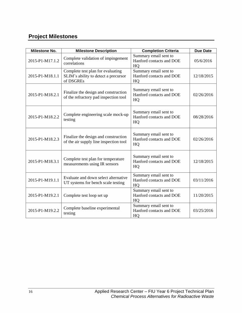
Project Milestones
Milestone No. Milestone Description Completion Criteria Due Date
2015-P1-M17.1.2 Complete validation of impingement
correlations
Summary email sent to
Hanford contacts and DOE
HQ
05/6/2016
2015-P1-M18.1.1
Complete test plan for evaluating
SLIM’s ability to detect a precursor
of DSGREs
Summary email sent to
Hanford contacts and DOE
HQ
12/18/2015
2015-P1-M18.2.1 Finalize the design and construction
of the refractory pad inspection tool
Summary email sent to
Hanford contacts and DOE
HQ
02/26/2016
2015-P1-M18.2.2 Complete engineering scale mock-up
testing
Summary email sent to
Hanford contacts and DOE
HQ
08/28/2016
2015-P1-M18.2.3 Finalize the design and construction
of the air supply line inspection tool
Summary email sent to
Hanford contacts and DOE
HQ
02/26/2016
2015-P1-M18.3.1 Complete test plan for temperature
measurements using IR sensors
Summary email sent to
Hanford contacts and DOE
HQ
12/18/2015
2015-P1-M19.1.1 Evaluate and down select alternative
UT systems for bench scale testing
Summary email sent to
Hanford contacts and DOE
HQ
03/11/2016
2015-P1-M19.2.1 Complete test loop set up
Summary email sent to
Hanford contacts and DOE
HQ
11/20/2015
2015-P1-M19.2.2 Complete baseline experimental
testing
Summary email sent to
Hanford contacts and DOE
HQ
03/25/2016

17 Applied Research Center – FIU Year 6 Project Technical Plan Chemical Process Alternatives for Radioactive Waste
Deliverables*
Client Deliverables Responsibility Acceptance Criteria Due Date
Draft Project Technical
Plan Project Manager
Acknowledgement of receipt via
E-mail two weeks after
submission
10/05/2015
Monthly Progress Report Project Manager
Acknowledgement of receipt via
E-mail two weeks after
submission
Monthly
Quarterly Progress
Reports (all tasks and
projects combined)
Principal
Investigator
Acknowledgement of receipt via
E-mail two weeks after
submission
Quarterly
Draft Year End Report
(all tasks) Project Manager
Acknowledgement of receipt via
E-mail two weeks after
submission
10/14/2016
Draft Summary Report
for Subtask 17.1.1 Project Manager
Acknowledgement of receipt via
E-mail two weeks after
submission
08/28/2016
Draft Summary Report
for Subtask 17.1.2 Project Manager
Acknowledgement of receipt via
E-mail two weeks after
submission
05/6/2016
Draft Test Plan for
Subtask 18.1.1 Project Manager
Acknowledgement of receipt via
E-mail two weeks after
submission
12/18/2015
Draft Summary Report
for Subtask 18.2.1 and
18.2.2
Project Manager
Acknowledgement of receipt via
E-mail two weeks after
submission
08/28/2016
Draft Summary Report
for Subtask 18.2.3 Project Manager
Acknowledgement of receipt via
E-mail two weeks after
submission
02/26/2016
Draft Summary Report
for Subtask 18.3.1 Project Manager
Acknowledgement of receipt via
E-mail two weeks after
submission
07/29/2016
Draft Summary
document for Subtask
19.1.1
Project Manager
Acknowledgement of receipt via
E-mail two weeks after
submission
03/11/2016
Draft Summary Report
for Subtask 19.2.2 Project Manager
Acknowledgement of receipt via
E-mail two weeks after
submission
04/8/2016
Presentation overview to
DOE HQ/Site POCs of
the project progress and
accomplishments (Mid-
Year Review)
Project Manager Presentation to DOE HQ and
Site POCs 02/29/2016**

18 Applied Research Center – FIU Year 6 Project Technical Plan Chemical Process Alternatives for Radioactive Waste
Presentation overview to
DOE HQ/Site POCs of
the project progress and
accomplishments (Year
End Review)
Project Manager Presentation to DOE HQ and
Site POCs 08/31/2016**
*Final documents will be submitted to DOE within 30 days of the receipt of comments on the
draft documents.
**Completion of this deliverable depends on availability of DOE-HQ official(s.)

19 Applied Research Center – FIU Year 6 Project Technical Plan Chemical Process Alternatives for Radioactive Waste
COMMUNICATION PLAN, ISSUES, REGULATORY POLICES AND HEALTH AND SAFETY
Communication Plan
The task has some elements that require significant information from the site in order to proceed
with the tasks. Therefore, the communication with the clients and relevant experts at Hanford &
SRS is a critical component of the task. The mode of communication will be e-mails,
telephone/conference call, and meeting at the site. Though site-specific contact persons have
been identified, constant communication will be maintained with client stakeholders at DOE HQ
and the Hanford sites to ensure all parties involved are aware of the task progress.
Information
Item Client Stakeholder When? Communication
Method Responsible
Stakeholder
Status Update
Teleconferences Hanford POC (R.
Mendoza, T. Sams, D.
Washenfelder, WRPS)
DOE EM-21
Monthly Phone call Project Manager
EM-HQ Status
Update Phone
Call
DOE EM Liaison to FIU Bi-Weekly Phone call Principal
Investigator
Quarterly Report DOE EM-21
WRPS End of Q1, Q2,
Q3,Q4 E-mail Principal
Investigator
Annual Year End
Report
DOE EM-21,
WRPS
45 days after
completion of
performance period
E-mail Principal
Investigator/
Project Manager
Deliverables,
Milestones
Hanford POC (R.
Mendoza, T. Sams,
WRPS)
DOE EM-21
At completion of
Deliverable,
Milestone
E-mail Project Manager/
Principal
Investigator
Anticipated Issues
Every year, South Florida has a 6-month hurricane season. Twice in the past decade FIU has
been closed 1-2 weeks due to hurricane storm damage. Care will be taken to minimize the
impacts on the overall schedule of milestones and deliverables due to hurricanes.
Project 1 tasks are supported by DOE Fellows and FIU graduate students. It is anticipated that 8
to 10 DOE Fellows and FIU graduate students will be supporting this project during FIU Year 6.
It is anticipated that research under this project may be used by students as the basis for a thesis
or dissertation towards a graduate degree and would be impacted by a re-direction of the project
task scope. FIU will communicate closely with DOE HQ and site contacts throughout the
performance of the research tasks in order to accurately forecast the duration of the research

20 Applied Research Center – FIU Year 6 Project Technical Plan Chemical Process Alternatives for Radioactive Waste
tasks and minimize the potential negative impact of scope redirection on the graduate studies of
any students working on that task.
Regulatory Policies and Health and Safety
Since laboratory experiments will be conducted on this project, FIU will ensure test plans are
developed and reviewed that cover staff health and safety issues. The nature of waste simulants
is that they are chemically the same as HLW and therefore highly caustic and hence hazardous.
In addition, FIU will set up, operate, and dismantle experimental test beds using proper
procedures from FIU and that comply with standards issued by the Occupational Safety and
Health Administration (OSHA). In order to minimize hazards, individuals will require
documentation of all needed online and classroom health and safety training prior to their being
authorized to work in the lab, on equipment, or on the test beds. Further, mandatory training is
provided to these individuals on workplace safety multiple times:
o Safety training at the time of initial assignment.
o Safety training prior to assignment involving new exposure situation (e.g., new
equipment or technology).
The Department of Health and Safety at FIU also provides other training relevant to specific
tasks or subtasks. Either FIU EHS or FIU ARC may request an audit by FIU EHS of safety
documentation, lab set up and procedures when there are any concerns by any staff working on
the task.