proportional integral &derivative controller for bldc motor · · 2015-10-29motor or it is...
TRANSCRIPT
International Journal of Advances in Engineering Research http://www.ijaer.com
(IJAER) 2014, Vol. No. 8, Issue No. V, November ISSN: 2231-5152
15
INTERNATIONAL JOURNAL OF ADVANCES IN ENGINEERING RESEARCH
PROPORTIONAL INTEGRAL &DERIVATIVE
CONTROLLER FOR BLDC MOTOR
T.Saarulatha1 M.E., V.Yaknapriya
2 M.E.,T.Muthukumar
3 M.E., S.Saravanan
4 M.E,
Ph.D., 1,2,3
Assistant Professor / EEE, 4Professor and Head/EEE
1,2,3,4MuthayammalEngineeringCollege,
ABSTRACT
The Brushless DC (BLDC) motors are one of the electrical drives that are now widely being used in
industrial applications and are rapidly gaining popularity, due to their high efficiency, good dynamic
response, high power density, high reliability, and maintenance-free reputation. These motors are
generally controlled using a three phase full bridge pulse width modulated (PWM) voltage source
inverter. For starting of the motor, for providing proper commutation sequence and to turn on the
power devices in the inverter bridge the rotor position sensors required. Based on the rotor position,
the power devices are commutated sequentially every 60 degrees. To achieve desired level of
performance the motor requires suitable speed controllers. In case of industrial drives, the speed
control is usually achieved by using Proportional-Integral-Derivative (PID) controller. PID
controllers are widely used in the industries due to their simple control structure and ease of
implementation. This paper presents a proportional-integral-derivative (PID) controller for the speed
control of BLDC motor. This work mainly focuses on the design of the speed controller for the closed
loop operation of BLDC motor. The PID speed Controller for the BLDC motor drive is designed and
simulated using MATLAB/SIMULINK software package. Thus a speed controller has been designed
successfully for closed loop operation of the BLDC motor and the motor runs very closed to the
reference speed.
Index Terms—Brushless DC (BLDC) motor, three phase full bridge pulse width modulated (PWM)
inverter, rotor position sensor, and Proportional-Integral-Derivative (PID) controller.
INTRODUCTION
Since the late 1980‟s new design concept of permanent magnet brushless motors has been
developed [1]. The permanent magnet brushless motor can be classified upon to the back-
EMF waveform, where it can be operated in either brushless AC (BLAC) or brushless DC
(BLDC) modes. Usually the BLAC motors have a sinusoidal back EMF waveform and BLDC
motors have a trapezoidal back EMF. BLAC motors with sinusoidal back-EMF waveform are
called as permanent magnet synchronous motors (PMSM). The Brushless DC Motor (BLDC)
motor is conventionally defined as a permanent magnet synchronous motor with a trapezoidal
back Electro Motive Force (EMF) waveform shape. The PMSM is very similar to the standard
wound rotor synchronous machine except that the PMSM has no damper windings and

International Journal of Advances in Engineering Research http://www.ijaer.com
(IJAER) 2014, Vol. No. 8, Issue No. V, November ISSN: 2231-5152
16
INTERNATIONAL JOURNAL OF ADVANCES IN ENGINEERING RESEARCH
excitation is provided by a permanent magnet instead of a field winding [2]. The PMSM has a
sinusoidal back EMF and requires sinusoidal stator currents to produce constant torque while
the BLDC motor has a trapezoidal back EMF and requires rectangular stator currents to
produce constant torque.
Compared to conventional DC motors and induction motors, BLDC motors have many
advantages and few disadvantages [3]. Comparing BLDC motors with DC motors, the DC
motor have high starting torque capability, smooth speed control and the ability to control
their torque and flux easily and independently. In the DC motor, the power losses occur
mainly in the rotor which limits the heat transfer and consequently the armature winding
current density, while in BLDC motor the power losses are practically all in the stator where
heat can be easily transferred through the frame, or cooling systems can be used specially in
large machines. Commutation of brushless DC motor to supply power from DC source is
performed with power electronic inverter rather than mechanical brushes. This enormously
improves the reliability of the system over brush DC motors. In addition it reduces the system
maintenance cost, and creates clean and safer working system environment. There is no brush;
there is no contamination and residual on the bearings. Also there is no arcing associated with
brushes; therefore BLDC motors are safer to work in condition where there exits danger of
explosive and wider contact with fluid. Brushless DC motor is much quieter both electrically
and audibly during operation. In general the induction motor has many advantages as: their
simplest construction, simple maintenance, low price and reliability. Furthermore, the
disadvantages of induction machines make the BLDC motors more efficient to use and
become more attractive option than induction motors. Some of the disadvantages of induction
machines are poor dynamic characteristics, lower torque at lower speeds and lower efficiency.
BLDC motor control system mainly comprises of DC voltage source, power electronics
inverter, rotor position sensor, and a controller. It is known that induction AC motors and
conventional DC motors can run by just connecting them to AC or DC source of power
supplies directly without any information about the rotor position. However, BLDC motor
control systems need rotor position information during operation. Commutation of brushless
DC motor to supply power from DC source is performed with power electronic inverter rather
than mechanical brushes. The rotor position information is used to perform electronic
commutations through power electronic inverter. In order to obtain the rotor pole position
either mechanical or electronic hardware sensor is used [4].
The rotor position sensor is selected depending on the application type, investment-cost, and
system environment. Mechanical rotor position sensor provides accurate rotor position
information than electronic sensor. This system is called Mechanical sensor control of BLDC
motor or it is usually referred to Sensor Control of BLDC motor. However, the cost of
mechanical rotor position sensors like encoder, tacho-meter, resolver, and Hall sensor are
expensive. Thus, investment cost of mechanical sensor control of BLDC motor is expensive
International Journal of Advances in Engineering Research http://www.ijaer.com
(IJAER) 2014, Vol. No. 8, Issue No. V, November ISSN: 2231-5152
17
INTERNATIONAL JOURNAL OF ADVANCES IN ENGINEERING RESEARCH
than electronic sensor control of BLDC motor. Therefore in the case of low-budgetBLDC
motor applications electronic sensors are preferred over mechanical rotor position sensor.
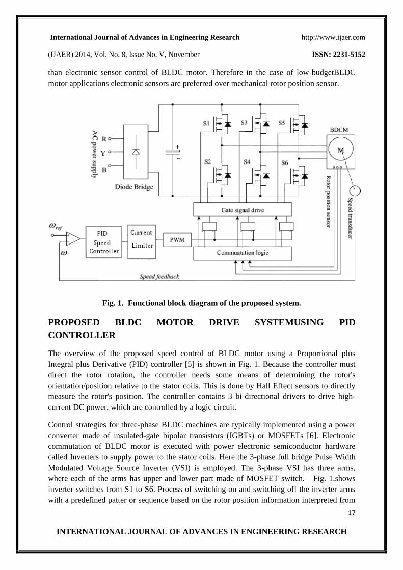
Fig. 1. Functional block diagram of the proposed system.
PROPOSED BLDC MOTOR DRIVE SYSTEMUSING PID
CONTROLLER
The overview of the proposed speed control of BLDC motor using a Proportional plus
Integral plus Derivative (PID) controller [5] is shown in Fig. 1. Because the controller must
direct the rotor rotation, the controller needs some means of determining the rotor's
orientation/position relative to the stator coils. This is done by Hall Effect sensors to directly
measure the rotor's position. The controller contains 3 bi-directional drivers to drive high-
current DC power, which are controlled by a logic circuit.
Control strategies for three-phase BLDC machines are typically implemented using a power
converter made of insulated-gate bipolar transistors (IGBTs) or MOSFETs [6]. Electronic
commutation of BLDC motor is executed with power electronic semiconductor hardware
called Inverters to supply power to the stator coils. Here the 3-phase full bridge Pulse Width
Modulated Voltage Source Inverter (VSI) is employed. The 3-phase VSI has three arms,
where each of the arms has upper and lower part made of MOSFET switch. Fig. 1.shows
inverter switches from S1 to S6. Process of switching on and switching off the inverter arms
with a predefined patter or sequence based on the rotor position information interpreted from
International Journal of Advances in Engineering Research http://www.ijaer.com
(IJAER) 2014, Vol. No. 8, Issue No. V, November ISSN: 2231-5152
18
INTERNATIONAL JOURNAL OF ADVANCES IN ENGINEERING RESEARCH
Hall Effect sensor, therefore, power will reach to the desired stator coils of the motor. Hence
current passes through two of the coils out of three stators.
Speed, torque, and phase currents/voltage are important variables in speed control of BLDC
machine. In controlling the speed of BLDC motor the system is closed-loop where actual
speed is the feedback parameter that is obtained from the speed transducer. A single stage PID
controller consisting of a speed loop has been used for the closed loop drivesystem. PID is
simplest and famous controller in Industry and Automation for motor application. The
purpose of the system controller is to minimize the error between the reference speed and the
feedback speed. In addition, it improves dynamic response and behavior of the system.The
function of the current limiter is to maintain the motor phase currents at their desired constant
value for each 120° interval that a particular phase is energized. The current is limited by
controlling the switch duty cycle to ensure that device current ratings and the motor current
rating are not exceeded, especially during start-up conditions or low speed operation. The
amount of current ripple is controlled by the switching frequency of a PWM waveform.The
gate driver is a drive circuitry which controls the current flow through the MOSFET switches.
Hence the current flow to motor windings is also controlled. This includes the direction and
magnitude of the current flow.
ROTOR POSITION SENSORSAND ELECTRONIC COMMUTATION
Unlike a brushed DC motor, the commutation of a BLDC motor is controlled electronically.
To rotate the BLDC motor, the stator windings should be energized in a sequence. It is
important to know the rotor position in order to understand which winding will be energized
following the energizing sequence. Rotor position is sensed using Hall Effect sensors
embedded into the stator. Most BLDC motors have three Hall sensors embedded into the
stator on the non-driving end of the motor. Whenever the rotor magnetic poles pass near the
Hall sensors, they give a high or low signal, indicating the N or S pole is passing near the
sensors. Based on the combination of these three Hall sensor signals, the exact sequence of
commutation can be determined. Fig. 2. shows an example of Hall sensor signals with respect
to back EMF and the phase current. Fig. 3.shows the switching sequence that should be
followed with respect to the Hall sensors.

International Journal of Advances in Engineering Research http://www.ijaer.com
(IJAER) 2014, Vol. No. 8, Issue No. V, November ISSN: 2231-5152
19
INTERNATIONAL JOURNAL OF ADVANCES IN ENGINEERING RESEARCH
Fig. 2. Hall Sensor Signal, Back EMF, Output Torque and Phase Current.
Sensor-less control of brushless dc motor in general and the back EMF method in particular
has drawbacks in estimating the rotor position at very low speed as the value of the back EMF
signal generated from the stator coil is very small to detect the rotor position. The rotor
position information is not available at standstill as the values of generated back EMF is zero.
Therefore Hall Effect sensor is employed here. Based on this, the motor manufacturer defines
the commutation sequence, which should be followed when controlling the motor
performance.
Each commutation sequence has one of the windings energized to positive power (current
enters into the winding), the second winding is negative (current exits the winding) and the
third is in a non-energized condition.Torque is produced because of the interaction between
the magnetic field generated by the stator coils and the permanent magnets. Ideally, the peak
torque occurs when these two fields are at 90° to each other and falls off as the fields move
together. In order to keep the motor running, the magnetic field produced by the windings
should shift position, as the rotor as the rotor moves to catch up with the stator field. Every 60
electrical degrees of rotation, one of the Hall sensors changes the state. Given this, it takes six
steps to complete an electrical cycle. In synchronous, with every 60 electrical degrees, the

International Journal of Advances in Engineering Research http://www.ijaer.com
(IJAER) 2014, Vol. No. 8, Issue No. V, November ISSN: 2231-5152
20
INTERNATIONAL JOURNAL OF ADVANCES IN ENGINEERING RESEARCH
phase current switching should be updated. However, one electrical cycle may not correspond
to a complete mechanical revolution of the rotor. The number of electrical cycles to be
repeated to complete a mechanical rotation is determined by
Fig. 3. Winding energizing sequence with respect to the Hall Sensor.
the rotor pole pairs. For each rotor pole pairs, one electrical cycle is completed. So, the
number of electrical cycles/rotations equals the rotor pole pairs. Table I shows the sequence in
which the power switches should be switched based on the Hall sensor outputs [7].
TABLE I
„ELECTRONIC COMMUTATION‟ BASED ON THE HALL-EFFECT
SENSOR SIGNALS
Hall Signals Conducting switches
Ha Hb Hc S1 S2 S3 S4 S5 S6
0 0 0 0 0 0 0 0 0

International Journal of Advances in Engineering Research http://www.ijaer.com
(IJAER) 2014, Vol. No. 8, Issue No. V, November ISSN: 2231-5152
21
INTERNATIONAL JOURNAL OF ADVANCES IN ENGINEERING RESEARCH
0 0 1 0 0 0 1 1 0
0 1 0 0 1 1 0 0 0
0 1 1 0 1 0 0 1 0
1 0 0 1 0 0 0 0 1
1 0 1 1 0 0 1 0 0
1 1 0 0 0 1 0 0 1
1 1 1 0 0 0 0 0 0
DESIGNOF PID CONTROLLER
In practice, the design of the BLDC motor servo system usually requires time consuming
complex process such as model, devise of control Scheme, simulation and parameters tuning.
Hence in this paper a simple PID controller based speed control has been proposed for BLDC
motor. The PID controller is highly suitable for the linear motor control [8].The PID
controller is the most common form of feedback. It was an essential element of early
governors and it became the standard tool when process control emerged in the 1940s. In
process control today, more than 95% of the control loops are of PID type, most. PID
controllers are today found in all areas where control is used. PID control is an important
ingredient of a distributed control system. The controllers are also embedded in many special
purpose control systems. PID control is often combined with logic, sequential functions,
selectors, and simple function blocks to build the complicated automation systems used for
energy production, transportation, and manufacturing.
In spite of developed modern control techniques like fuzzy logic controllers or neural
networks controllers, PID controllers constitute an important part at industrial control systems
so any improvement in PID design and implementation methodology has a serious potential to
be used at industrial engineering applications [9]. At industrial applications the PID
controllers are preferred widespread due to its robust characteristics against changes at the
system model. There is another reason why this project using PID controller instead another
method. The first is the three terms are reasonable intuitive, allowing a no specialist grasp the
essentials of the controller‟s action. Second, PID has a long history, dating back to a pre-
digital, even pre-electronic period and lastly the introduction of digital control has enhanced
PID‟s capabilities. In general the advantages of PID controller can be summarized as follows:
1. PID controllers do not require advanced mathematics to design.
2. It can be easily tuned unlike other complicated algorithms based on
optimal control theory.
International Journal of Advances in Engineering Research http://www.ijaer.com
(IJAER) 2014, Vol. No. 8, Issue No. V, November ISSN: 2231-5152
22
INTERNATIONAL JOURNAL OF ADVANCES IN ENGINEERING RESEARCH
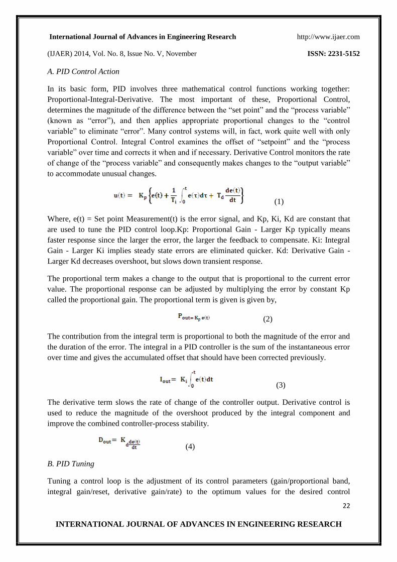
A. PID Control Action
In its basic form, PID involves three mathematical control functions working together:
Proportional-Integral-Derivative. The most important of these, Proportional Control,
determines the magnitude of the difference between the “set point” and the “process variable”
(known as “error”), and then applies appropriate proportional changes to the “control
variable” to eliminate “error”. Many control systems will, in fact, work quite well with only
Proportional Control. Integral Control examines the offset of “setpoint” and the “process
variable” over time and corrects it when and if necessary. Derivative Control monitors the rate
of change of the “process variable” and consequently makes changes to the “output variable”
to accommodate unusual changes.
(1)
Where, e(t) = Set point Measurement(t) is the error signal, and Kp, Ki, Kd are constant that
are used to tune the PID control loop.Kp: Proportional Gain - Larger Kp typically means
faster response since the larger the error, the larger the feedback to compensate. Ki: Integral
Gain - Larger Ki implies steady state errors are eliminated quicker. Kd: Derivative Gain -
Larger Kd decreases overshoot, but slows down transient response.
The proportional term makes a change to the output that is proportional to the current error
value. The proportional response can be adjusted by multiplying the error by constant Kp
called the proportional gain. The proportional term is given is given by,
(2)
The contribution from the integral term is proportional to both the magnitude of the error and
the duration of the error. The integral in a PID controller is the sum of the instantaneous error
over time and gives the accumulated offset that should have been corrected previously.
(3)
The derivative term slows the rate of change of the controller output. Derivative control is
used to reduce the magnitude of the overshoot produced by the integral component and
improve the combined controller-process stability.
(4)
B. PID Tuning
Tuning a control loop is the adjustment of its control parameters (gain/proportional band,
integral gain/reset, derivative gain/rate) to the optimum values for the desired control
International Journal of Advances in Engineering Research http://www.ijaer.com
(IJAER) 2014, Vol. No. 8, Issue No. V, November ISSN: 2231-5152
23
INTERNATIONAL JOURNAL OF ADVANCES IN ENGINEERING RESEARCH
response. The process of determining the values of these parameters is known as PID Tuning.
If the PID controller parameters (the gains of the proportional, integral and derivative terms)
are chosen incorrectly, the controlled process input can be unstable, i.e. its output diverges,
with or without oscillation, and is limited only by saturation or mechanical breakage.
Instability is caused by excess gain, particularly in the presence of significant lag. Generally,
stability of response is required and the process must not oscillate for any combination of
process conditions and set points, though sometimes marginal stability (bounded oscillation)
is acceptable or desired.
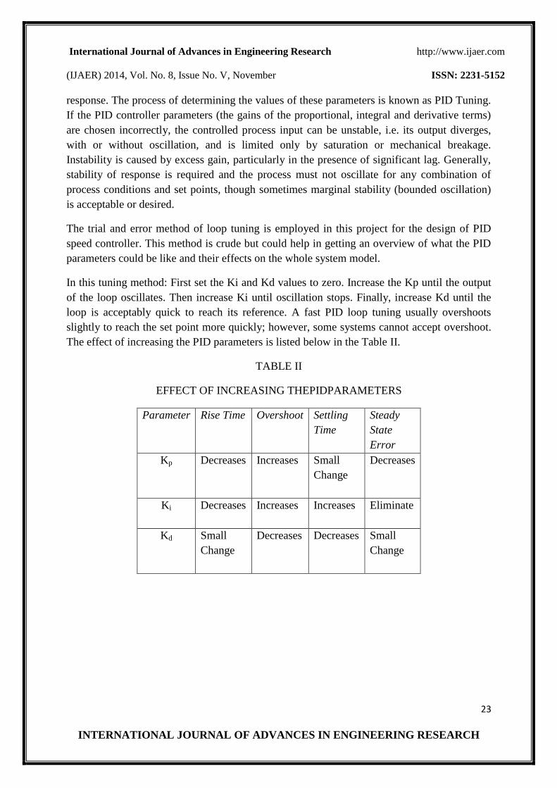
The trial and error method of loop tuning is employed in this project for the design of PID
speed controller. This method is crude but could help in getting an overview of what the PID
parameters could be like and their effects on the whole system model.
In this tuning method: First set the Ki and Kd values to zero. Increase the Kp until the output
of the loop oscillates. Then increase Ki until oscillation stops. Finally, increase Kd until the
loop is acceptably quick to reach its reference. A fast PID loop tuning usually overshoots
slightly to reach the set point more quickly; however, some systems cannot accept overshoot.
The effect of increasing the PID parameters is listed below in the Table II.
TABLE II
EFFECT OF INCREASING THEPIDPARAMETERS
Parameter
Rise Time
Overshoot
Settling
Time
Steady
State
Error
Kp
Decreases
Increases
Small
Change
Decreases
Ki
Decreases
Increases
Increases
Eliminate
Kd
Small
Change
Decreases
Decreases
Small
Change

International Journal of Advances in Engineering Research http://www.ijaer.com
(IJAER) 2014, Vol. No. 8, Issue No. V, November ISSN: 2231-5152
24
INTERNATIONAL JOURNAL OF ADVANCES IN ENGINEERING RESEARCH
C. Implementation of PID Speed Controller
Fig. 4. Implementation of PID Speed Controller.
Fig. 4. shows the implementation of PID speed controller in the speed control of BLDC motor
drive system [10]. The speed can be controlled in a closed loop by measuring the actual speed
of the motor. The error in the set speed and actual speed is calculated. The PID speed
controller is used to amplify the speed error and dynamically adjust the PWM duty cycle.
SIMULATIONUSING MATLAB
The closed loop speed control of a BLDC motor using PID controller is simulated using
MATLAB 7.9 software package based on the Simulation Circuit as shown in Fig. 6.The test
parameters of the motor taken for simulation are given below.
TABLE III
BLDC MOTOR SPECIFICATIONS
Motor Parameters Values
Rated power 1 KW
No. of phases 3
Rated voltage 400 V dc
Stator resistance/phase 2.875 Ω
Stator Inductance/phase 0.0085 H
Moment of Inertia 0.0008 Kg-m/sec2
Rated speed 3000 rpm
The calculated gains of PID controller are provided in Table IV. The simulation results for
speed reference input of 1000 rpm with the calculated PID tuning parameters are shown in
Fig. 5.

International Journal of Advances in Engineering Research http://www.ijaer.com
(IJAER) 2014, Vol. No. 8, Issue No. V, November ISSN: 2231-5152
25
INTERNATIONAL JOURNAL OF ADVANCES IN ENGINEERING RESEARCH
TABLE IV
PIDTUNING PARAMETERS
PID PARAMETERS
Kp Ki Kd
40
225
0.3
(a) Rotor Speed vs. Time.
(b) Phase Current Waveform for Phase-A.
(c) Back EMF Waveform for Phase-A.
Fig. 5.Simulation Results.

International Journal of Advances in Engineering Research http://www.ijaer.com
(IJAER) 2014, Vol. No. 8, Issue No. V, November ISSN: 2231-5152
26
INTERNATIONAL JOURNAL OF ADVANCES IN ENGINEERING RESEARCH
Fig. 6.Simulation Circuit for the speed control of BLDC motor drive system using PID
controller.
CONCLUSION
In this paper, the PID controller was used as a vital technical tool for the closed loop speed
control of BLDC motor drive system.The system controller design and the parameters
identification are based on the simulation carried out on using SIMULINK/MATLAB.Also
the “Trial and Error method” of PID controller tuning is presented and applied to brushless
DC motor. This method is feasible due to the unique and simplified structure of the BLDC
motor. The PID controller thus designed has been simulated and observed to have good
performance. The maximum overshoot is found to be very less which is a good result. So a
speed controller has been designed successfully for closed loop operation of the BLDC motor
and the motor runs very closed to the reference speed.
REFERENCES
[1]. T. J. E. Miller, Brushless Permanent Magnet & Reluctance Motor Drives. Clarendon
Press, Oxford, Vol.2, pp: 192-199, 1989.
International Journal of Advances in Engineering Research http://www.ijaer.com
(IJAER) 2014, Vol. No. 8, Issue No. V, November ISSN: 2231-5152
27
INTERNATIONAL JOURNAL OF ADVANCES IN ENGINEERING RESEARCH
[2]. B. K. Bose, Modern power electronics and AC drives. Pearson Education, 2002 edition.
[3]. MICROCHIP AN885 technical report, Brushless DC (BLDC) Motor Fundamentals.
Microchip Technology Inc, 2003.
[4]. N. J. Ham, C. J. Hammerton, and D. Sharples, Power Semiconductor Applications
Manual. Philips Semiconductors, 1994.
[5]. Zhi Yang Pan, and Fang Lin Luo, “Novel Resonant Pole Inverter for Brushless DC Motor
Drive System,” IEEE transactions on power electronics, Vol.20, No.1, January 2005.
[6]. Anand Sathyan, Nikola Milivojevic, Young-Joo Lee, Mahesh Krishnamurthy, and Ali
Emadi, “An FPGA-Based Novel Digital PWM Control Scheme for BLDC Motor Drives,”
IEEE transactions on industrial electronics, Vol. 56, No. 8, August 2009.
[7]. Sanjeev Singh, and Bhim Singh, “A Voltage-Controlled PFC Cuk Converter-Based
PMBLDCM drive for Air-Conditioners,” IEEE transactions on industry applications, Vol.
48, No. 2, March/April 2012.
[8]. Atef Saleh Othman Al-Mashakbeh, “Proportional Integral and Derivative Control of
Brushless DC Motor,” European Journal of Scientific Research, ISSN 1450-216X Vol.35
No.2 (2009), pp.198-203.
[9]. M. Belsam Jeba Ananth, C. S. Ravi Chandran, “Design of PID Controller for a Linear
Brushless DC Motor using Soft Computing Techniques,” European Journal of Scientific
Research, ISSN 1450-216X Vol.73 No.3 (2012), pp. 357-363.
[10]. AN2892 Application Note on, 3-Phase BLDC Motor with Hall Sensors and Speed
Closed Loop, Driven by eTPU on MCF523x. Freescale Semiconductor, Inc., 2005.