qualification procedures for making heat fusion joints chevron bulletin no. 10… · qualification...
TRANSCRIPT

Qualification Proceduresfor making heat fusion joints.
Chevron
.
.
BULLETIN NO.1 OSY
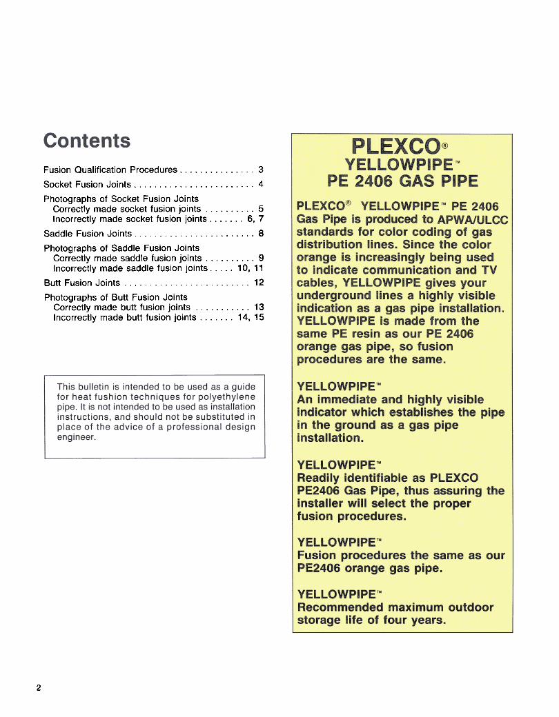
Fusion Qualification Procedures. 3
Socket Fusion Joints. 4
Photographs of Socket Fusion JointsCorrectly made socket fusion joints. 5Incorrectly made socket fusion joints. 6, 7
Saddle Fusion Joints. 8
Photographs of Saddle Fusion JointsCorrectly made saddle fusion joints. 9Incorrectly made saddle fusion joints. 10' 11
Butt Fusion Joints. 12
Photographs of Butt Fusion JointsCorrectly made butt fusion joints. 13Incorrectly made butt fusion joints. 14, 15
2

Chevron
This bulletin is intended to serve as an aid for thetraining of personnel as qualified installers ofPLEXCO polyethylene pipe in compliance with theregulations of the Department of Transportation,Materials Transportation Bureau, contained in theCode of Federal Regulations Title 49, Part 192.Section 192.285 of these regulations details theprocedure to be used to qualify persons to join plasticpipe.* As part of this qualification process, the traineemust make sample fusion joints in accordance withthe applicable qualified fusion procedure. Theresultant fused joints must have the same visualappearance as correctly made fusion joints describedand illustrated in this bulletin. In addition, each jointmust be cut into at least 3 longitudinal strips, each ofwhich is visually examined and found not to containvoids or discontinuities on the cut surfaces of the jointarea; and deformed by bending, torque, or impact
-such that if failure o~curs it doe.s not occur in the jointWarea. Refer to Bulletin 101 FusIon Procedures for
complete fusion procedures.
The pictures in this bulletin are of correctly andincorrectly made socket, saddle and butt fusion joints.They are presented to assist the user in evaluatingheat fusion joints.
PLEXCO polyethylene pipe and fittings should bejoined only by the heat fusion method. DO NOTattempt to join by threading or with solvent cements. Ifyou use mechanical fittings, instructions for their useshould be obtained from the fittings manufacturer.
A fusion joint is made in four simple steps:
1. Be sure that the surfaces of the fusion tools, pipeand fittings are free of contaminants prior to use.
2. Heat the surfaces to be joined -both the pipe andfittings -simultaneously at a prescribed temperaturefor a specified time.
3. Remove the heater -bring melted surfacestogether.4. Hold until solidified.
Before you begin fusing, here are some points toremember:
1. All heater surfaces have a thin layer of non-stickcoating that is easily scratched or scraped off. Thiscoating prevents melted PE from adhering firmly to theheater surfaces but occasionally it, too, must becleaned.
Metal tools should NEVER be used to clean the heatersurfaces because they scratch and remove the coating.
Wood implements and clean, dry, lint-free rags arerecommended for cleaning. All-cotton rags arerecommended because rags containing a substantialamount of synthetic fibers may melt and char againstthe heater surface.
If the non-stick coating becomes worn or scratched, thefusion surfaces of the heating unit should be recoated.
Melted PE adheres firmly to the heating iron and ismore difficult to remove at places where the coatinghas been scraped off .
In addition, since the coating acts as an insulator, heattransfer in these uncoated areas is greater and localoverheating can occur.
2. Just before using, wipe heaters to remove dirt andforeign material. Clean heaters as soon as possibleafter using with wood implements, and clean rags toremove melted or charred plastic.
3. Check the heater temperature with crayon indicatorsor surface pyrometer at least once a day to make surethe thermometer or other temperature measuringdevice is reading accurately.
Under heavy use conditions, check temperature twice aday.
4. NEVER lay a heating unit on the soil or grass whenthe heat cycle is completed. Return it to holder, ifpossible, or at least lay it on a board. Soil willcontaminate the joint and is abrasive to the coating;grass may burn and char on the heater surface.
Important: All fusion Equipment must be in properworking order. Consult the manufacturer's operatingmanual for maintenance and service procedures. Donot use defective equipment.
'192.2850 Each operator shall establish a method to determinethat each person making joints in plastic pipelines in his system isqualified in accordance with CFR 49, 192.285.
3

8. Snap the heating tool and fitting from the meltedpipe by holding upper part of tool handle with onehand and rapping sharply on the handle with the freehand.
Immediately remove fitting from heating tool.
9. Inspect the heated parts quickly to make sure allsurfaces have been melted.
If melt is not complete, cut off melted pipe end, use anew fitting, and repeat fusion steps 1 through 8.
PREPARE PIPE ENDS
1 .Using a pipe cutter, squarely cut off damaged oroval ends of pipe.
2. Use chamfering tool to remove the sharp cornerat the pipe end. Remove burrs and chips inside pipeends.
3. To prepare pipe for correct penetration intosocket, place depth gauge down flush on end ofpipe.4. Place cold ring clamp around pipe, adjacent todepth gauge.After securing cold ring clamp, remove depth gauge.
5. Fitting surfaces should be clean and dry -wipewith cloth -do not touch with hands.
6. The socket faces of the heating tool should be at5000 :t 10° F and clean .
7. First, firmly seat the socket fitting on the maleface of the heating tool.
Then place the female face on the end of the pipefirmly against the cold ring clamp.
Heating time starts when the cold ring is bottomedout on the heater surface.
HEA TING
Heat for the prescribed period of time, DO NOTTWIST PIPE, FITTING OR HEATING TOOL.
FUSION AND COOLING
10. Within 3 seconds after the heating tool has beenremoved, firmly push the melted fitting squarely ontothe pipe until it makes firm contact with the cold ringclamp.DO NOT TWIST OR ROTATE THE FITTING.
Hold the fitting firmly in place for total cooling timeshown in Table 1 to insure proper alignment.
After waiting 3 additional minutes cooling time,remove the cold ring clamp and inspect the joint.
A good joint will have a uniform melt ring that is flatagainst the socket and perpendicular to the pipe.
There should be no gaps or voids between the fittingand the pipe.
11. Wait an additional 10 minutes to complete coolingbefore the pipe joint is tested or stressed duringburial.
12. See Figure 1 for visual parameters of a properfusion .
T ABLE 1 -SOCKET FUSION TIME CYCLES
*Guidelines only, exact time depends upon environmentalconditions and condition of fusion equipment.
4

.
.
..
5
(FIGURE 2) CORRECTBEND TEST FOR SOCKET FUSION JOINT
Allow the joint to cool for at least one hour beforesubjecting it to a bend test.
Cut at least 3 strips 111 wide lengthwise through thesocket so that about 8" of pipe remains on each sideof the fitting.
No gaps or voidswhen bentHold each strip at the ends, and bend the sample as
shown in Figure 2.
Continue to hold each sample in the bent position,and thoroughly examine the entire fusion area. If anyseparation, cracks or voids are observed, thefusion is not satisfactory.
~
A joint is considered satisfactory if all bent samplesare completely free of cracks or voids in the fusionarea, as shown in Figure 2.

Fusion bond length too short
Heated part of fitting notcovered by pipe
Melt pressed againstcoupling -fusion appearsacceptable
Cooler part of pipe insertedinto fitting creates void
Pipe inserted too far
~
Incorrect bead -melt notpressed against fitting

~
(FIGURE 5) POOR ALIGNMENT (INCORRECT)
~
(FIGURE 6) MEL T RUBBED OFF WHENREMOVING HEATER
(FIGURE 7) MEL T RUBBED OFF WHENREMOVING HEA TER
"'
7
~
Breaks when bent -no melt bead
~

4. After proper melt time, raise fitting and removeheater from pipe.
DO NOT displace melt on pipe and fitting surfaces.
Check melt pattern on pipe and fitting -heatedsurfaces on fitting and pipe should be 100% meltedwith no cold spots.
(Use a mirror to check the melt on the under surface ofthe saddle base.)
5. If melt patterns are satisfactory, press the fitting onthe pipe very quickly (within 3 seconds) with firmpressure until a melt bead of the following size appearsaround the entire base of the fitting:
It is recommended that an application tool be usedwhen making saddle fusion joints. Variables in theinstallation procedure are more easily controlled whena tool is used than when the fusion is made manually.When fusing on a pressurized main, the risk ofblow-out can be reduced by using equipment thatis in proper working order, following themanufacturer's operating instructions, usingrecommended fusion procedures and by usingrelieved-center heater faces when fusing HighVolume Tapping Tees.
1. Assemble application unit according tomanufacturer's instructions and use bolster plates on 6"IPS and smaller mains.
2. Remove surface skin from the melt areas of theclean, dry pipe and saddle fitting by roughening with50 to 60 grit utility cloth.
Brush away residue with dry rag after roughening.3. With the heating surfaces of the tool at 500° ::t: 10°Fplace the tool in position on pipe.
Place fitting against heater faces and apply pressure.
Heat under pressure for time shown in Table 2 or 3.
TABLE 2- TAPPING TEE AND SERVICE SADDLEFUSION TIME CYCLES
**Use heat shield on pipe surface for first 15 seconds of thistime cycle.
TABLE 3- HVTT AND BRANCH SADDLEFUSION TIME CYCLES
Adjust fusion unit to maintain pressure of fitting on pipe.See tip card for further information.
Allow fusion joint to cool for at least the times indicatedin Table 2 or 3 before releasing pressure.
If melt pattern on fitting or pipe is unsatisfactory afterheating, apply fitting to pipe and let cool. Removecutter from tapping tee and cut off fitting top to avoidmisuse later. Repeat procedure from Step 1.
6. After letting joint cool 3 minutes beyond that shownin the tables, remove application unit from pipe.
Visually check fitting for fusion melt bead around entirefitting base.
If fusion joint quality is unacceptable or doubtful, cut offfi!ting top and apply a new fitting to a new section ofpipe.
7. For standard tapping tees and service saddles, letfusion cool an additional 10 minutes prior to pressuretesting and tapping the main. For high volume tapping,tee and branch saddles, allow an additional 30minutes.
8. See Figures 8 and 9 for visual parameters of aproper fusion.
*Guidelines only, exact time depends upon environmentalconditions and condition of fusion equipment.
With experience, the iron can be rocked slightly andslowly as the melt forms-do not rock excessively asthis will enlarge the melt pattern on the pipe.
8

9

(FIGURE 11) COLD FUSION -EXCESSIVE COOLING BEFORE JOINING
(FIGURE 12) POOR ALIGNMENT -FITTING NOT FLA T ON PIPE
(FIGURE 13) POOR ALIGNMENT -FITTING NOT SQUARE ON PIPE

(FIGURE 15) OVERMEL TING -INSIDE PIPE(FIGURE 14) INCOMPLETE PIPE MEL T PATTERN
"
(FIGURE 16) OVERMEL TING -
HEA T CYCLE TOO LONG

9. Allow the butt fusion to cool, under pressure, forthe time shown in Table 4.
10. DO NOT remove the fused joint from theequipment for an additional 3 minutes aftercooling time.
DO NOT test, stress, pull or lay in ground for 10 to60 minutes after removal from fusion unit.
11 .See Figure 18 for visual parameters of aproper fusion.
Each bead after fusion should have approximatelythe following diameters:
1. Clean each pipe end with a clean cloth. Placepipe ends into fusion machine. Bring ends togetherand check alignment.
2. Insert facing unit between pipe ends and lock ontoguide rods. Face pipe ends to the stops.
3. Check alignment of pipe ends. Adjust high-Iow ifnecessary. If adjustment is made, reinsert facing unitand reface to the stops.
4. Check heater plate for temperature and wipesurface clean.
5. Insert heater plate between aligned ends and bringends firmly in contact with plate, but DO NOTAPPLY PRESSURE.
6. Heat for times shown below.
TABLE 4- BUTT FUSION TIME CYCLES "
*Guidelines only, exact time depends upon environmentalconditions and condition of fusion equipment.
7. Remove heater plate after achieving proper meltbead.
8. Bring melted ends together rapidly. DO NOTSLAM. Apply enough force to achieve a double rollback of each bead onto the pipe. Hold this pressure
during cooling.
12

Chevron
13

(FIGURE 21)INCOMPLETE FACING BEND TEST(FIGURE 20) INCOMPLETE FACING
(FIGURE 23)POOR ALIGNMENT BEND TEST(FIGURE 22) POOR AliGNMENT

(FIGURE 24) "COLD JOINT" -EXCES-SIVE PRESSURE DURING HEAT CYCLE (FIGURE 25) COLD JOINT BEND TEST
(FIGURE 26) MEL T BEAD TOO SMALL (FIGURE 28) MEL T BEAD TOO LARGE
(FIGURE 27) SMALL BEAD BEND TEST
15