radial axle truck test results report
TRANSCRIPT

REPORT NO. FRA/ORD-82/25
RADIAL AXLE TRUCK TEST RESULTS REPORT
■Ffipared for:U.S. DEPARTMENT OF TRANSPORTATION
FEDERAL RAILROAD ADMINISTRATION OFFICE OF FREIGHT & PASSENGER SYSTEMS
4 0 0 SEVENTH STREET, S.W. WASHINGTON, D.C. 20590
APRIL 1982
Prepared by:
TRANSPORTATION TECHNOLOGY ENGINEERING DIVISIONENSCO, INC.
5400 PORT ROYAL ROAD -------------------------------------- N SPRINGFIELD, VA 2215103 - Rail Vehicles St !Components i
s
Technical Report Documentation Page1. Report No.
FRA/ORD-82/252. Government Accession No. 3. Recipient's Catalog No.
4. Title and Subtitle
RADIAL AXLE TRUCK TEST RESULTS REPORT5. Report Dare
March. 19826. Performing Organization Code1444/204-02
7. A u th o r 's )
M. Lj.les, R. Scofield8. Performing Organization Report No.
DOT-FR-82-069. Performing Organization Name and AddressENSCO, INC.Transportation Technology Engineering Divisior 5400 Port Royal Road Springfield, VA 22151
10. Work Unit No. (TR A IS )
1 1. Contract or Grant No.DTFR53-80-C-0000212. Sponsoring Agency Nome and Address
Office of Freight and Passenger Systems Federal Railroad Administration Department of Transportation Washington, DC 20590
13. Typo o i Report and Period Covered
Final Report
14. Sponsoring Agency Code
15. Supplementary Notes
Contract Technical Monitor RICHARD L. SCHARR, Office of Freight § Passenger Systems
16. A bstract
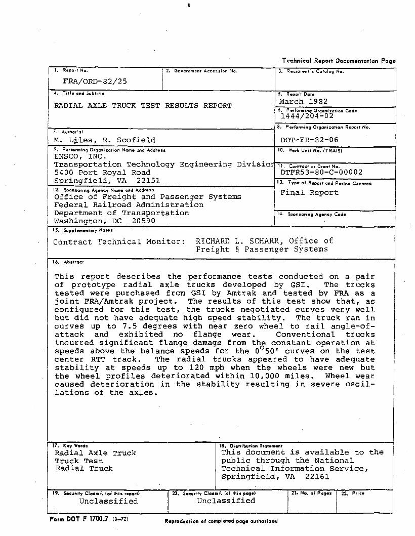
This report describes the performance tests conducted on a pair of prototype radial axle trucks developed by GSI. The trucks tested were purchased from GSI by Amtrak and tested by FRA as a joint FRA/Amtrak project. The results of this test show that, as configured for this test, the trucks negotiated curves very well but did not have adequate high speed stability. The truck ran in curves up to 7.5 degrees with near zero wheel to rail angle-of- attack and exhibited no flange wear. Conventional trucks incurred significant flange damage from the constant operation at speeds above the balance speeds for the 0°50' curves on the test center RTT track. The radial trucks appeared to have adequate stability at speeds up to 120 mph when the wheels were new but the wheel profiles deteriorated within 10,000 miles. Wheel wear caused deterioration in the stability resulting in severe oscillations of the axles.
17. Kay Wards
Radial Axle Truck Truck Test Radial Truck
18. D is tribu tion StotomantThis document is available to the public through the National Technical Information Service, Springfield, VA 22161
19. Security C la s s if. (o f th is rsport) 20. Security C la s s if. (of th is pago) 21* No. of Pages 22. P r ie .
Unclassified Unclassified
Form DOT F 1700.7 (8-72) Reproduction of completed page authorized

fv.r i rtIC cyA V E R S IO N FACTORS
Approximate Conversions to Metric Measures
Symbol When You Know Multiply by To Find Symbol8
LENGTH
in inches *2.5 centimeters cmft feet 30 centime tare cmyd yards 0.8 meters mmi miles 1.6 ' kilometers km
AREA
in8 square inches 6.5 square centimeters cm?ft* square feet 0.08 square meters m*yd* square yards 0.8 square meters m2mi* square miles 2.6 square kilometers km*
acres 0.4 hectares ha
MASS (weight}
os ounces 28 grams glb pounds 0.45 kilograms kg
short tons 0.9 tonnes t(2000 lb)
VO LUM E
tsp teaspoons 6 milliliters mlTbsp tablespoons 16 milliliters mlfl oz fluid ounces 30 milliliters mlc cups 0.24 liters 1pt pints 0.47 liters 1qt quarts 0.86 liters 1gal gallons 3.8 liters 1ft* cubic feet 0.03 cubic meters m*yd* cubic yards 0.76 cubic meters m3
TEM PERATURE (exact}
°F Fahrenheit 5 /9 (after Celsius oCtemperature subtracting temperature
321
7
6
6
4-
3
2
in. - 2 .64 cm (exactly). Fa r other exact conversions and m ore detail tables see ~NBS Mlsc. Publ. 206. Units a t W eight and Measures. Price $ 2 .2 6 SO Catalog N o. 0 3 ?0 28®. inches
23Approximate Conversions from Metric Measures
22
21Symbol When You Know Multiply by To Find Symbol
20LENGTH
19 mm millimeters 0.04 inches incm centimeters 0.4 inches in
18 m meters 3.3 feet Hm meters 1.1 yards yd
17km kilometers 0 .6 miles mi
16 AREA
>16 cm* square centimeters 0.16 square inches in*m* square meters 1.2 square yards yd*km* square kilometers 0.4 square miles mi*
•14 ha hectares (10,000 m * i 2.6 acres
13
-12MASS (weight)
g grams 0.035 ounces OZ•1 1 kg kilograms 2.2 pounds lb
t tonnes (1000 kg) 1.1 short tons10
- 9 VOLUME
8 ml milliliters 0.03 fluid ounces fl oz1 liters 2.1 pints P«1 liters 1.06 quarts q»- 7 1 liters 0.26 gallons galm* cubic meters 36 cubic feet ft*
- 6 m3 cubic meters 1.3 cubic yards yd*
- 6 TEMPERATURE (exact)- 4 °c Celsius 9 /5 (then Fahrenheit °F
temperature add 32) temperature-3
°F- 2 °F 32 98.6 212
- 4 0 0 140 80 I 120 160 200 |-1 I I I 1 1 1 I I | 1 1 l ( l I, 1 1 l I I I 1 1 1 1 1
1 r i l f l T 1 r 1 | 1- 4 0 _ 2 0 I 20 |4Q 60 80 100
cm U(J 0 37 °C

TABLE OF CONTENTS
Section Title PageEXECUTIVE SUMMARY ix
1.0 INTRODUCTION 1-12.0 TECHNICAL APPROACH 2-1
2.1 Test Sequence 2-12.1.1 Shop Tests 2-12.1.2 Shakedown Test 2-12.1.3 Cutaway Braking Test 2-22.1.4 Concept Demonstration Test 2-32.1.5 Performance Test 2-32.1.6 Life Test 2-3
2.2 Instrumentation 2-42.3 Detailed Description of Test Article 2-14
3.0 TEST DESCRIPTION 3-13.1 Shop Tests 3-1
3.1.1 Purpose 3-13.1.2 Carbody Clearance 3-13.1.3 Truck to Carbody Clearance 3-23.1.4 Suspension System Centering 3-33.1.5 Handbrake Test 3-33.1.6 Equalization Test 3-53.1.7 Leveling System Test 3-53.1.8 Axle Alignment 3-5
3.2 Shakedown Test 3-73.2.1 Purpose 3-73.2.2 Test Sequence 3-73.2.3 Track Mapping 3-73.2.4 Shakedown Test 3-8
3.3 Cutaway Braking Test 3-83.3.1 Purpose 3-83.3.2 Instrumentation 3-83.3.3 Test Procedure 3-9
iii

Section
4 o 0
TABLE OF CONTENTS (Cont'd) Title
3.4 Concept Demonstration and Performance3.4.1 Purpose3.4.2 Actual Test Sequence3.4.3 Instrumentation3.4.4 Test Results
3.5 Ride Quality Test3.5.1 Purpose3.5.2 Test Sequence3.5.3 Test Procedures3.5.4 Ride Quality Data Analysis
3.6 Life Test3.6.1 Purpose and Planned Sequence3.6.2 Actual Life Tests
3.7 Fatigue Test TEST RESULTS4.1 Introduction4.2 Shop Tests4.3 Cutaway Braking Tests4.4 Shakedown Test4.5 Truck Performance
4.5.1 Curve Negotiation4.5.2 Stability4.5.3 Steering Bias in the Lead Truck4.5.4 Effects on Tread Wear4.5.5 Conclusions on Stability
4.6 Ride Quality Test Results
3-103-103-103-143-143-153-153-153-153-153-173-173-173- 194- 14-14-14-34-34-34-34-274-354-354-414-42
Page
iv

LIST OF FIGURESFigureNumber Title Paqe1-1 Cross-Linked Radial Truck 1-21-2 Straight-Linked Radial Truck 1-22-1 Radial Truck Test Instrumentation
Configuration 2-52-2 Transducer Locations 2-62-3 Location of A-End Junction Boxes 2-72-4 Truck Instrumentation 2-82-5 Truck Cross Links 2-212-6 Wheel Profile 2-213-1 Braking Curves for Full Service 3-113-2 Braking Curves for Emergency Service 3-124-1 Summary of Results for Axle/Axle Alignment
on Leading Radial Truck when Tested on 3, 4, 5 and 7.5 Degree Curves 4-3
4-2 Summary of Results for Axle-to-Axle Angle vs. Cant Deficiency for Lead Radial Truck when Tested on 3, 4, 5 and 7.5 Degree Curves 4-5
4-3 Summary Results of Axle Alignment of Leading Truck on Radial Truck Car for Tests on 3,4, 5 and 7.5 Degree Curves 4-6
4-4 Summary Results of Axle-to-Axle Alignment as a Percentage of an Ideal Radial Alignment for 3, 4 , 5 and 7.5 Degree Curves for CW and CCW Tests on FAST 4-7
4-5 Ideal Axle Alignment 4-84-6 Summary Results of Axle-to-Axle Alignment
for Trailing Radial Truck 4-94-7 Summary of Axle-to-Axle Alignment for Trailing
Radial Truck 4-10
V

FigureNumber
LIST OF FIGURES (Cont'd)
Title Page
4-8 Axle-to-Axle Alignment for Trailing RadialTruck 4-11
4-9 Summary of Axle-to-Axle Alignment for theTrailing Radial Truck 4-12
4-10 Angle of Attack and Axle Alignment for Counter Clockwise Rotation on Left Hand Curves and Clockwise Rotation on Right Hand Curves 4-13
4-11 Range of Wheel Angle-of-Attack 4-144-12 Truck Angle of Attack Results for A-Truck of
the Radial Car 4-154-13 Truck Angle of Attack Results for the
B-Truck Radial Car 4-164-14 Truck Angle of Attack Data for the A-Truck
Reference Test Car 4-174-15 Angle of Attack Results from the Leading Axle
of the Radial and Reference Truck from 5 Degree Right Hand and 5 Degree Left Hand FAST Curves 4-22
4-16 Angle of Attack Results from the Leading Axle of the Radial and Reference Truck from 5 Degree Right Hand and 5 Degree Left Hand FAST Curves 4-23
4-17 Angle of Attack Results from the Leading Axle of the Radial Truck from 5 Degree Right Hand and 5 Degree Left Hand FAST Curves 4-24
4-18 Angle of Attack Results from the Leading Axle of the Radial and Reference Truck from 5 Degree Right Hand and 5 Degree Left Hand FAST Curves 4-25
4-19 Summary of Test Results Showing Angle ofAttack vs Speed for Leading Axle of RadialTruck on 3, 4 and 5 Degree Curves 4-26
v i

FigureNumber4-20
4-21
4-224-23
4-24
4-25
4-26
4-27
4-28
LIST OF FIGURES (Cont'd)
TitleSelected Data Channels for Soft Suspension (Stiffness C) Counterclockwise on RTT, Location 550 to 450f 105 mphSelected Data Channels for Soft Suspension (Stiffness C) Counterclockwise on RTTRTT and Balloon LoopAxle-to-Axle Oscillation Amplitude, Lead Radial TruckSelected Data Channels for Soft Suspension (Stiffness "A") Counterclockwise on RTT at Location 460, 95 mphSelected Data Channels for Firm (Stiffness "C") Suspension Counterclockwise on RTT, Location 550 to 450, 95 mphSelected Data Channels for Firm (Stiffness "C") Suspension with Dampers Counterclockwise on RTT, Location 550 to 450, 116 mphSelected Data Channels for Firm (Stiffness "C") Suspension Counterclockwise on RTT, Location 550 to 450, 118 mphSelected Data Channels for Firm Stiffness "C" Suspension Clockwise on RTT, Location 450 to 550, 108 mph 1
4-31
4-324-33
4-34
4-36
4-37
4-38
4-39
4-40
Page
V I 1

LIST OF TABLESTableNumber Title Paqe2-1 Instrumentation Channel Assignment 2-82-2 Radial Truck Direct and Scaled Outputs 2-122-3 Sample Digital Map from EDAP 2-152-4 Channel Table from EDAP 2-163-1 Carbody Roll Data on 6-1/4 Inch Crosslevel 3-23-2 Centering Test Data 3-43-3 TTC Curve Criteria 3-83-4 Full Service Braking Data 3-133-5 Emergency Service Braking Data 3-133-6 Comparison of Radial Truck Equipped Car
and Car Equipped with Pioneer III Trucks 3-163-7 Data Channels for Stiff Sandwich Test 3-184-1 Ideal Axle Alignment Data 4-18
v i i i

EXECUTIVE SUMMARYThe Radial Axle Truck Test was performed to evaluate a cross- linked radial axle truck designed and produced by General Steel Industries Incorporated (GSI) for Amtrak. This was a joint FRA/ Amtrak project performed to evaluate the potential of the radial axle truck concept for high-speed passenger service. The test was conducted at the Transportation Test Center (TTC), Pueblo, Colorado. ENSCO, Inc. conducted the Performance Tests and was supported by TTC/Boeing Services International (BSI). TTC/BSI conducted the Life Tests. Both tests were supported by Amtrak and GSI.
The radial axle trucks experienced a number of problems at the beginning of the testing, which delayed the schedule, but were corrected. Planned tests were condensed and the essence of the original test plan was accomplished. In the end, the test showed that the cross-linked radial truck had very good curving ability, but, as configured, the truck did not have adequate stability. Minor oscillations of the axles seemed to cause wheel wear which in turn reduced the stability. When the wheel treads were new the truck was judged to have adequate stability with a slight tendency to display axle oscillations. The truck was tested at speeds up to 126 mph. Within 10,000 miles of operation, the wheels developed a detectable wear which increased the effective conicity. As the wear increased, the operating speed had to be reduced to avoid violent oscillation of the axles.
The results seem to indicate that the optimum trade-off between curving and stabilitiy was not achieved despite attempts by GSI to modify the truck. The trucks maintained near perfect radial alignments with zero angle of attacks between the wheels and rail on all curves up to and including the 7.5 degrees balloon loop curve (which was the sharpest curve at the test center) . GSI made several attempts to increase the truck primary spring longitudinal stiffness to improve the stability but each time the initial success was quickly negated by the deterioration of the wheel profiles. The hollowing of the wheels increased the effective conicity leading to marked reduction in the critical speed.
The results seem to indicate that radial trucks have potential, but that they are very sensitive to alignment and wheel wear. The linked radial truck concept would appear to be a good candidate for service which demands good curving performance at slower speeds. If the radial truck can be made to have adequate highspeed stability it may have potential for operations when the equipment operates at speeds significantly above balance speeds. In high-speed operation on the 14 mile closed loop Railroad Test Track (RTT) at the test center, the Pioneer III truck (which is the truck presently used on the Amcoach cars) developed substantial flange wear. In contrast, the radial truck displayed no flange wear and in fact, seldom, if ever, were the flanges in contact with the rail.
ix

1.0 INTRODUCTION
Amtrak and FRA sponsored a joint program to test and evaluate the radial axle truck concept for high speed passenger service. The performance related radial axle truck tests were started in the spring of 1980 and were completed in the fall of the same year. The life (endurance) tests began in November 1980 and ended in June 1981. The radial axle truck tests were performed at the Transportation Test Center (TTC) for the Office of Passenger Systems, Federal Railroad Administration/Department of Transportation. The performance tests were conducted by ENSCO, Inc. under contracts with DOT/FRA with support from the truck manufacturer (GSI), Amtrak and TTC. Other portions of the overall radial axle truck test and the life tests, were conducted by TTC with assistance from other parties.
The radial axle truck concept has been around for more than 100 years. Within the past 20 years, there has been a growing interest in this truck concept. The general definition of a radial truck is a truck constructed so that the axles align, perpendicular to the rail as the truck negotiates curved sections of track.
Two types of linkages have been developed for frictional force steering and are presently being used for freight radial axle trucks. These truck configurations are shown by Figures 1-1 and1-2. The passenger trucks tested by this program are cross linked radial trucks. The leading and trailing axles are connected by cross linkages as shown in Figure 1-1. To allow the axles to align to the curve as desired, the longitudinal stiffness of the journal must be made relatively soft which results in partial decoupling of the wheels and axles from the truck frame reducing the effective mass of the wheels and axles. This normally makes a truck unstable because the kinematic oscillation of the wheelsets occurs at a speed within the range of the desired operating speed. Therefore, the relatively soft longitudinal spring stiffness of this radial truck allows curving and crosslinks allow curving while the crosslinks provide longitudinal stiffness between axles and thus improve stability. The radial axle truck concept has been analyzed in many of the truck dynamics studies. The result of these studies are reported in recent papers. Papers prepared by the Massachusetts Institute of Technology and by Battelle Memorial Institute provide a review of the theory which supports the radial truck concept.
1 - 1

1 - 2

2 .0 TECHNICAL APPROACH
This program was designed to evaluate the use of the radial axle truck concept for high speed passenger car applications. The prototype radial trucks were installed under The Budd Company built Amcoach car specially modified to receive the trucks. The Amcoach car equipped with the radial trucks was run in the test with another Amcoach equipped with Pioneer III trucks (normally provided by The Budd Corporation for the Amcoach fleet). Results of the radial truck performance were compared in many of the tests to the data obtained from the reference car trucks. The performance tests shown below were conducted by ENSCO with TTC assistance. The life tests (presented in a different report) were conducted by TTC.
The radial truck test was originally divided into seven test series. However, due to the performance problems of the radial trucks the technical approach was modified to the following five tests:
• Shop Test• Shakedown Test• Cutaway Braking Test• Concept Demonstration/Performance Test• Life Test
( Performance ( Tests
} Life Test
2.1 TEST SEQUENCE2.1.1 SHOP TESTSThe shop tests were performed to confirm that the new trucks were rail-worthy. The shop test consisted of:
• Carbody clearance test• Truck to car clearance test• Suspension centering test• Handbrake test
2.1.2 SHAKEDOWN TESTThe shop test was followed by the shakedown test to first wear-in the brake pads and to test the truck at successively increased speeds. In the process of increasing the speed, both truck and axle stability and axle alignment were monitored in curved and tangent sections of track and during brake applications. The
2 - 1

initial test on the Railroad Test Track (RTT) showed that the car leaned to one side excessively in the curves. When first tested at low speeds, the car body roll was as high as 12 degrees. At the same time the curving data showed that the wheels of the radial truck remain flanged to the right on both the right and left hand curves. Both of these problems had to be resolved before the other tests could be performed properly. The carbody leveling corrections and truck axle/link alignment are discussed in the TTC test report.
The shakedown test series gave the truck manufacturer an opportunity to make adjustments to the truck. Through pre-test plan development meetings, procedures were developed for bringing the truck up to full operational performance. The truck manufacturer requested tests to evaluate the following aspects:
• Truck Longitudinal Stiffness — The manufacturer had three different longitudinal shear sandwiches available for the primary suspension system to check variation to stability.
• External Axle Yaw Damping — External yaw dampers were installed to check stability increase at high speeds (120 + mph).
• Journal Box Tilt — The truck journal box tilt was checked to determine if braking causes excessive rotation of the journal boxes.
• Bump Stop Clearance — The carbody lateral acceleration was measured to evaluate the lateral bump stop clearance.
• Braking Rate — ■ The braking rate and the disk to tread brake ratio were varied.
These checks were incorporated into the testing schedule for the shakedown test series. The shakedown tests were scheduled to be conducted on both the 14 mile (closed loop) Railroad Test Track (RTT) , the balloon loop, and on the smaller FAST oval. In addition, tests were performed on the screech loop.
2.1.3 CUTAWAY BRAKING TESTAfter the truck stability had been checked, cutaway braking tests were performed to evaluate the braking rate and disk to tread ratio. These tests were performed to confirm that the brake rate of the new trucks matched conventional Amcoach cars. The disc and wheel temperatures were checked during the speed upgrade to insure that the brake components were not overheating.
2 - 2

2.1.4 CONCEPT DEMONSTRATION TESTOn completion of the cutaway brake test, concept demonstration tests were performed. This series of tests were designed to demonstrate and evaluate the curving characteristics and high speed stability of the radial truck and to compare its performance to the manufacturer's claims.
The primary performance claims were:
• Less wheel tread and flange wear• Increased high speed stability• Better ride qualty• Less component wear• Less rail wear (no data collected)• Lower noise levels on curves (observed only)• Reduced traction power (no data collected)
The concept demonstration tests were designed to evaluate the first four of the performance features.
2.1.5 PERFORMANCE TESTAfter the concept demonstration test, a similar series of tests were performed to document the truck performance under a variety of different speeds and curve conditions. The tests were performed on the RTT track at speeds up to 120 mph and on the FAST curves at speeds which correspond to cant deficiencies from 3 inches under balance to 3 inches over balance. In addition to the normal running test, the performance test series included a simulated cross link failure test and a deflated air bag test*
2.1.6 LIFE TESTThe life test series was intended to include enough mileage to determine if the truck had any severe wear problems and to evaluate the effects of wheel and component wear. The high speed performance was scheduled to be checked at the beginning of the life test and after 40,000 miles and again after another 40,000 miles at the completion of the life test. The primary responsibilities for the life test were assigned to TTC, therefore, the details on this, phase of the program will be covered in a separate report published by TTC.
2-3

2.2 INSTRUMENTATIONThe instrumentation system (Figure 2-1) used for the radial truck test utilized the data acquisition and processing system of the T-7 test coach. The heart of this system is a Hewlett-Packard 21MX Minicomputer. The HP 21MX was equipped with a 1600 BPI tape drive, a disk drive mass storage unit, a graphics terminal and a Versatec video printer. The data were multiplexed and digitized by an Analogic 5400 data acquisition system. Sample timing was controlled by an ENSCO real-time clock interface.
Signal conditioning for the transducers was housed in racks adjacent to the computer and signals to and from the signal conditioners were routed by means of patch panels to anti-aliasing filters.
Four junction boxes located on the ends of the Amcoaches connected the signals from the individual transducers to the Dekeron cables which carried signals to T-7's bulkhead connectors. Location of A-end radial coach junction boxes, typical of all installations may be seen in Figure 2-3.
Typical truck instrumentation is seen in Figure 2-4, while a schematic location of truck mounted transducers is shown in Figure 2-2. A listing of data channels, location, full scale sensitivities, transducer type, filter frequency, etc., is in Table 2-1.
A data acquisition operating system software was written for the Radial Truck Test. This system, ENSCO Digital Data Acquisition System (EDDAS), allows versatile operation and the display of pre-programmed real-time calculations while continuing to gather data at a high rate. The channels, once programmed, are treated as if they were raw data supplied by transducers and can be displayed beside directly produced data. Since the calculated channels are produced from raw channels the calculations were not recorded on tape. Calculated channels are identified by "200 level" channel numbers, i.e., 210, 212, etc.
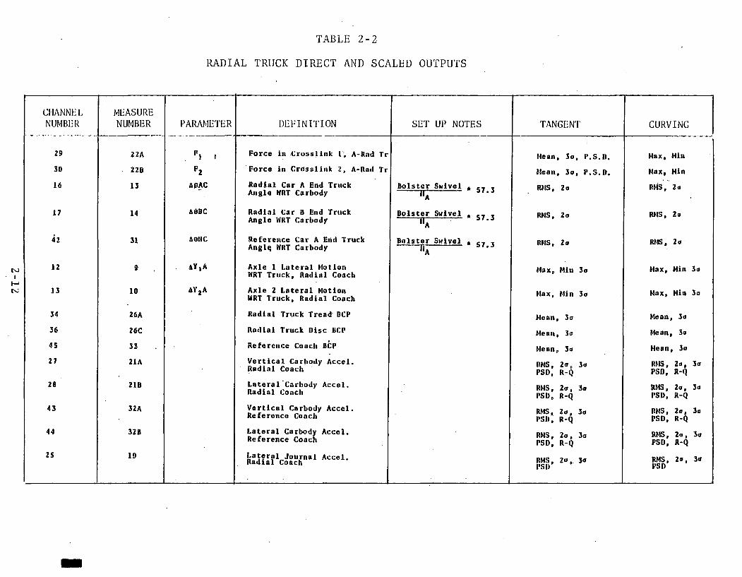
Some channels were used directly or scaled with the signal conditioning. These channels and their analysis is shown in Table2- 2.
For data reduction the EDDAS system had a playback-only version named Reduction Digital Data Acquisition System (RDDAS). RDDAS allowed measured or calculated analog data to be played back on pen recorders along with indications of manually entered milepost and event data, automatic location detector and a count of the
2-4

.•ay*©
RADIAL TRUCK 1EST CONFIGURATION
toILn
R E F E R E N C E R A D I A L
,\\ \ \ \ ' 7 0 6 \
R E F . A
7 0 7 J2 4V )
js ^ jsTR AIN
2 STRAINGAGES
yG A G E S
PATCH FIELD
J-B O X I R A D -A
7 0 5 '
IIs.p .
19
J - B O X 2 " A24Av
C A LC A R D
19
T TopDC
CONTROL
RQPTz)J - B O X 3
J PATCH FIELD *
C A LC A R D
R A b -B
24 VM v l
O
( 4J
W\200'\\\\N\'SC'2 4 V 3 0 0
ACCEL12)
PATC
ELD
CHARGEAM P
710
X V 7 0 3 , \ \
^ Z Z IE ^7 0 4 X V
A L PT A C H
INPUT
pATChi
PANEL
2 4 V D C
~ |l o c q . a c c e l T I
o y n a m ic
7 CHA N . SIG .
nX is s Ps\ V
\ \ l 2 S R \V
e n s c o15 AMPS
15 S.P.ENSCO
15 AMPS 12 S.P.
: I5 5 P.
> 2 ^
ENSCOAMPS
R0PI4)
AO A
8 C IIA n
4 CHAN AMP
3 CHANS B C P
4 CHAIJS ACCEL'S
A LOCONO.
S P E E D f DISTANCE
F8LTER
PA
H
PANE
Figure 2-1. Radial Truck Test Instrumentation Configuration
luZcooo
u» —-jhlliq: u
kw
w

I
27A2 U '34A2 T~~r
ioE
5g [7g] if
\
/
( j
£u li r J ) 1327B2 ll4l
(31)
- H w | —4 A I6A
Hi
tONSISTH l e f t
/
\
J-T-r~r
-------kea ■» 19.
■* 71-^1? 9 A
22A
26C25
22 B\
\
26 A
AEND
i8A| 6A
ISA 3AI
1B[m h >
*loONSISTRIGHT
\5A 0 ) 17 A1— 1
A-ENDLE F TS ID E
I
B -A X LE VIEW A-A A -A X L E
Q REFERENCE COACH
| j "B" RADIAL TRUCK
VIEW B-B
A END. RIGHT SIDE (REVERSED)
Figure 2-2. Transducer Locations
2 - 6

Figure 2-3. Location of A-End Junction Boxes
2-7

TABLE 2-1INSTRUMENTATION CHANNEL ASSIGNMENT
CHANNEL TRANSDUCERNUMBER MEASUREMENT TRANSDUCER
TYPE LOCATION
0 3A Vertical Motion of Primary Suspension
±5" Bridge Type String Pot
A-End Radial Truck A-Axle Left Side
1 3B Vertical Motion of Primary Suspension
±5" Bridge Type String Pot
A-End Radial Truck A-Axle Left Side
2 4A Vertical Motion of Primary Suspension
±5" Bridge Type String Pot
A-End Radial Truck B-Axle Left Side
3 4B Vertical Motion of Primary Suspension
±5" Bridge Type String Pot
A-End Radial Truck B-Axle Left Side
4 5A Longitudinal Motion of Frame to Journal
±5" Bridge Type String Pot
A-End Radial Truck A-Axle Left Side
5 5B Longitudinal Motion of Frame to Journal ±5" Bridge Type String Pot A-End Radial Truck
A-Axle Right Side6 6A Longitudinal Motion
of Frame to Journal ±5” Bridge Type String Pot A-End Radial Truck
B-Axle Left Side7 6B Longitudinal Motion
of Frame to Journal ±5" Bridge Type String Pot A-End Radial Truck B-Axle Right Side
8 7A Longitudinal Motion of Frame to Journal
±5" Bridge Type String Pot
B-End Radial Truck A-Axle Left Side
9 7B Longitudinal Motion Frame to Journal
±5" Bridge Type String Pot
B-End Radial Truck A-Axle Right Side
10 8A Longitudinal Motion Frame to Journal
±5" Bridge Type String Pot
B-End Radial Truck B-Axle Left Side
11 8B Longitudinal Motion Frame to Journal
±5" Bridge Type String Pot
B-End Radial Truck B-Axle Right Side
12 9 Lateral Motion of Frame to Journal Reed Gage A-End Radial Truck
A-Axle Right Side13 10 Lateral Motion of
Upper Box to JournalReed Gage A-End Radial Truck
B-Axle Left Side14 LI Lateral Motion Truck
Bolster to Carbody±5" Bridge Type String Pot A-End Radial Truck
15 12 Lateral Motion Truck Bolster to Carbody ±5" Bridge Type String Pot B-End Radial Truck
16 13 Truck Frame to Bolster Swivel
±15" Bridge Type String Pot A-End Radial- Truck
17 14 Truck Frame to Bolster Swivel
±15" Bridge Type String Pot B-End Radial Truck
18 15A Journal Tilt ±5" Bridge Type String Pot A-End Radial Truck
A-Axle Left Side
2 - 8

INSTRUMENTATION CHANNEL ASSIGNMENTTABLE 2-1 (cont)
CHANNELTRANSDUCERNUMBER MEASUREMENT TRANSDUCERTYPE LOCATION
19 15B Journal Tilt ±5" Bridge Type String Pot
A-End Radial Truck A-Axle Right Side
20 16A Journal Tilt ±5" Bridge Type String Pot
A-End Radial Truck B-Axle Left Side
21 16B Journal Tilt ±5" Bridge Type String Pot
A-End Radial Truck B-Axle Right Side
22 17A Longitudinal Motion Truck Frame to Upper Box
Reed Gage A-End Radial Truck A-Axle Left Side
23 17B Longitudinal Motion Truck Frame to Upper Box
Reed Gage A-End Radial Truck A-Axle Right Side
24- 18 Lateral Motion Upper Box to Journal Reed Gage A-End Radial Truck
A-Axle Left Side25 19 Lateral Acceleration
of Journal 'PCB• Brand Piezo ±50g Accelerometer
A-End Radial Truck A-Axle Left Side
26 20 Vertical Acceleration of Journal 1PCB’ Brand
Piezo ±50g Accelerometer
A-End Radial Truck A-Axle Left Side
27 21A Vertical Acceleration of Carbody
RQP #1 A-End Radial Coach28 21B Lateral Acceleration ,
of CarbodyRQP #1 A-End Radial Coach
29 22k Longitudinal Force on Steering Rod
Strain Gage supplied by MFR
A-End Radial Coach
30 22B Longitudinal Force on Steering Rod Strain Gage
supplied by MFR A-End Radial Coach31 23 Longitudinal Force
on Damper Link Strain Gage supplied by MFR A-End Radial Truck
A-Axle Right Side32 24 Vertical Strain
on Bolster Strain Gage supplied by MFR A-End Radial Truck
33 25 Strain on Disc Brake Rigging Strain Gage
supplied by MFR 1 A-End Radial Truck34 26A Brake Cylinder Pres
sure on Tread Brakes 2000 psi Gulton A-End Radial Truck A-Axle Left Side
2-9
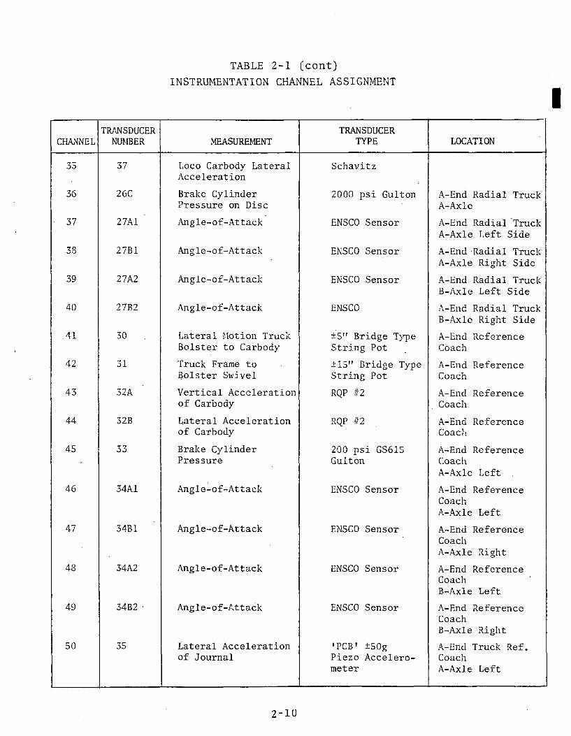
TABLE 2-1 (cont)INSTRUMENTATION CHANNEL ASSIGNMENT
CHANNELTRANSDUCERNUMBER MEASUREMENT
TRANSDUCERTYPE LOCATION35 37 Loco Carbody Lateral
Acceleration Schavitz
36 26C Brake Cylinder Pressure on Disc 2000 psi Gulton A-End Radial Truck
A-Axle■ 37 27A1 Angle-of-Attack ENSCO Sensor A-End Radial Truck
A-Axle Left Side38 27B1 Angle-of-Attack ENSCO Sensor A-End Radial Truck
A-Axle Right Side39 27A2 Angle-of-Attack ENSCO Sensor A-End Radial Truck
B-Axle Left Side40 27B2 Angle-of-Attack ENSCO A-End Radial Truck
B-Axle Right Side41 30 Lateral Motion Truck
Bolster to Carbody ±5" Bridge Type String Pot A-End Reference
Coach42 31 Truck Frame to
Bolster Swivel ±15" Bridge Type String Pot. A-End Reference
Coach43 32A Vertical Acceleration
of Carbody RQP #2 A-End Reference Coach
44 32B Lateral Acceleration of Carbody RQP #2 A-End Reference Coach
45 T *TJO Brake Cylinder Pressure 200 psi GS615
Gulton A-End Reference CoachA-Axle Left
46 34A1 Angle-of-Attack ENSCO Sensor A-End Reference CoachA-Axle Left
47 34B1 Angle-of-Attack ENSCO Sensor A-End Reference CoachA-Axle Right
48 34A2 Angle-of-Attack ENSCO Sensor A-End Reference CoachB-Axle Left
49 34B2 * Angle-of-Attack ENSCO Sensor A.-End Reference CoachB-Axle Right
50 35 Lateral Acceleration of Journal
'PCS' ±50g Piezo Accelerometer
A-End Truck Ref. CoachA-Axle Left
2 - 1 0

TABLE 2-1 (cont)INSTRUMENTATION CHANNEL ASS I G N M E N T
CHANNELTRANSDUCERNUMBER MEASUREMENT
TRANSDUCERTYPE LOCATION
51 36 Vertical Acceleration of Journal
'PCB1 ±50 g Accelerometer
A-End Truck Ref. CoachA-Axle Left
52 28 Dist. Wheel Tach 1000 CPR
T-7
53 29 ALD ENSCO ALD Sensor T-754 Reference 5V p-p
10 Hz. sq. waveOscilloscopeCalibrator
T-7
55 38A Long Force on Cross Link
Strain Gage B-End Radial Coach
56 38B Long Force on Cross Link
Strain Gage B-End Radial, Coach
2 - 1 1
-12
TABLE 2-2
RADIAL TRUCK DIRECT AND SCALED OUTPUTS
ISO
CHANNEL MEASURENUMBER NUMBER PARAMETER DEFINITION SET UP NOTES TANGENT
29 2 2A Fi >F o r c e i n C r o s s l i n k 1 ; A -R a d T r M e a n , 3 o , P . S . D .
3 0 220 F 2 F o r c e i n C r o s s l i n k 2 , A-Ra<l T r M e a n , 3 o , P . S . D .
16 13 flpAC R a d i a l C a r A End T r u c k A n g l e WRT C a r b o d y
B o l s t e r
" T
S w i v e i * 5? 3 RMS, 2o
17 14 46BC R a d i a l C a r R End T r u c k A n g l e WRT C a r b o d y .
B o l s t e r
“ a
S w i v e l . „ j RMS, 2a
42 31 aeNC R e f e r e n c e C a r A End T r u c k A n g lq WRT C a r b o d y
B o l s t e r
----------- ° A
S w i v e l * S7 3 RMS, 2a
12 9 a y , a A x l e 1 L a t e r a l M o t i o n WRT T r u c k , R a d i a l Coach
M a x , M il t 3o
13 10 a y 2 a A x l e 2 L a t e r a l M o t i o n WRT T r u c k , R a d i a l Coach
M a x , M in 3o
34 26A R a d i a l T r u c k T r e a d ' DCP M e a n , 3o
36 26C R a d i a l T r u c k D i s c UCP M e a n , 3o
45 33 R e f e r e n c e C oach DCP M e a n , 3o
27 21A V e r t i c a l C a r b o d y A c c e l . R a d i a l C oach
RM S, 2 o , 3a P S D , R -q
28 2 1 D L a t e r a l C a r b o d y A c c e l . R a d i a l C oach R M S , 2 a , 3a
P S D , R - q
43 32A V e r t i c a l C a r b o d y A c c e l . R e f e r e n c e Coach
R M S, 2 a , 3a P S D , R - q
44 32B L a t e r a l C a r b o d y A c c e l . R e f e r e n c e C o a ch
RMS, 2 o , 3o PSD , R -q
25 19 k a 5 ? r ? l J o u r n a l A c c e l . R a d i a l Coach RMS, 2a , 3o
PSD
CURVING
M a x , M in
M a x , M in
RMS, 2o
RMS, 2o
RMS, 2o
M a x , M in 3o
M a x , M in 3a
M e a n , 3o
M e an , 3o
M e a n , 3o
RMS, 2 o , 3a PSD, R-Q
RMS, 2o , 3o PSD, R-Q
RMS, 2 a , 3a PSD, R-q
RMS, 2 a , 3a PSD, R-q
RMS, 2o , 3a PSD

£1 =
RADIAL TRUCK DIRECT AND SCALED OUTPUTSTABLE 2-2 (cont)
CHANNEL MEASURENUMBER NUMBER PARAMETER DEFINITION SET UP NOTES TANGENT CURVING
26 20 V e r t i c a l J o u r n a l A c c e d . R a d i a l Coach RMS, 2 o , 3<i
PSDRMS, 2 o , 3o PSD
50 35 L a t e r a l ' J o u r n a l A c c e l . R e f e r e n c e Coach
RMS, 2 o , 3o PSD
RMS, 2o , 3a PSD
51 36 V e r t i c a l J o u r n a l A c c e l . R e f e r e n c e C oach RMS, 2 o , 3o
PSDRMS, 2 a , 3a PSD
31 23 F o r c e in D am per L i n k M e a n , 3 o , PSD M e a n , 3 o , PSD
32 24 i . S t r a i n i n B o l s t e r M e a n , 3o , PSD M e a n , 3 o , PSD
33 25 S t r a i n i n D r a k e R i g g i n g M e a n , 3o , PSD M e a n , 3 a , PSD
53 29 ALD None None ■
35 31 L a t e r a l C a r b o d y A c c e l , L o c o . RMS, PSD , Max. RMS, PSD, M a x .
SS 3BA F3 F o r c e i n C r o s s l i n k 3 B - U a d i n I T r u c k Mean, 3 o , P . S . D . M a x , Min
56 380 r<i F o r c e i n C r o s s l i n k 4 B - R a d i a l T r u c k M e a n , 30 , P . S . D . M a x , Min

current data record in which the data were stored. Playback in the EDDAS mode produces an analog map that allows the analyst to select data from a lengthy tape for intensive analysis.
A tape duplication program allowed selected records to be recorded on another tape to provide a condensed data tape to minimize tape handing.
Another program developed for this test, ENSCO Data Analysis Program (EDAP), provided digital data analysis of an EDDAS data tape. EDAP allowed the analyst to digitally map a data tape. The map provides distance, event type and number, speed, time of day, and position in the tape information which can be combined with the analog map to provide an accurate location of test phenomena. A sample digital map is shown in Table 2-3.
Another feature of EDAP is the channel table, shown in Table2-4. The channel table is interactive with the data analysis program in that a change in the scale or equation will change the output value. This feature is useful for correcting errors in the setup that are detected at a later date.
Once the analyst has decided what data are to be analyzed, he can select the analysis start and stop points from any record, ALD, milepost, or event plus up to 9999 feet to any other or the same record. Thus, the same distance, time or area track loction can be selected as the analysis base and specific start and stop points such as ALD's are not needed.
The analyst has the choice of analyzing all measured and calculated channels at one time for maximum, minimum, mean, RMS and standard deviation or any 16 channels for all of the above analysis plus 1st, 5th, 95th and 99th percentile values.
2.3 DETAILED DESCRIPTION OF TEST ARTICLEThe radial truck used in this test has the following features:
• Each truck has a cast rigid frame.• Summiride air bags are used for the secondary
suspension and the bolster serves as the reservoir for the air suspension and leveling system.
2-14
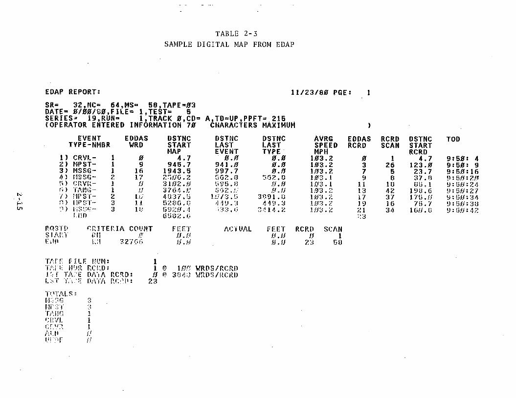
TABLE 2-3SAMPLE DIGITAL MAP FROM EDAP
EDAP REPORT 1 1 / 2 3 / 8 0 PGE: 1
SR= 3 2 , NC= 6 4 , MS" 5 8 sTAPE=03 DATE= 0 / 0 0 / 8 0 , F ILE® 1 ,T E S T » 5S E R IE S * 1 9 , RUN" 1 , TRACK 0 , C D = A , T D = UP »PPFT= 2 15(OPERATOR ENTERED INFORMATION 7 0 CHARACTERS MAXIMUM )
EVENT EDDAS DSTNC DSTNC DSTNC AVRG EDDAS RCRD DSTNC TODTYPE-NMBR WRD START LAST LAST SPEED RCRD SCAN START
MAP EVENT TYPE MPH RCRD1 ) CRVL- 1 0 4 . 7 0 . 0 0 . 0 1 0 3 . 2 0 1 4 . 7 9 : 5 0 4Z ) MPST- 1 9 9 4 5 . 7 941 . 0 0 . 0 1 0 3 . 2 3 26 1 2 3 . 0 9 : 5 0 93 ) M8SG- 1 16 1 9 4 3 . 5 9 9 7 . 7 0 . 0 1 0 3 . 2 7 5 2 3 . 7 9 : 5 0 164 > m s s g - 2 17 2 0 0 0 . 2 5 0 2 . 0 5 6 2 . C 1 0 3 . 1 9 B 3 7 . 0 9 : 5 0 2 05 ) C R V l i - 1 0 3 1 0 2 . 0 5 9 5 . 8 0 . 0 1 0 3 . 1 1 1 IB CU. 1 9 : 5 0 24fi > TANG- 1 tj 3 7 6 4 . 0 0 0 2 . f j 0 . 0 1 0 3 . 2 13 42 1 9 0 . 6 9 : 5 0 277 ) M P S T - 2 10 4 3 3 7 . 5 1 0 / 3 . 5 3 8 9 1 . 0 1 0 3 . 2 17 37 1 7 5 . 0 9 : 5 0 3 40 ) lir’ S T - 3 11 5 2 8 0 . G 4 4 9 . 3 4 4 9 . 3 1 0 3 . 2 19 16 7 5 . 7 9 : 5 0 300 ) 3 18 5 9 2 0 . 4 •'■33. 0 3 4 1 4 . 2 1 0 3 . 2 21 34 1 0 0 . E! 9 : 5 0 42i.niJ 0 5 8 2 . 0 2 3
TP C R I T E R I A COUNT FEET ACTUAL FF.FT RCP.P SCANs’.Y p h />■ 0 . 0 0 . 0 0 1
R!'l r%* 2 7 0 0 0 . 0 0 . 0 23 GO
TArr- F R F I'UMs TAi 'F HOR RCRD:V > . f TA.'E DA'i A RCRD * I .ST ' f . D A T A RCAI.1:
11 0 1 0 0 VRDS/RCRD0 0 3 8 4 0 V/RDS/RCRD
2 3
TOTALS:ID 3GB i t C1 !TANG 1CRVL 1cr.w3. 1ALP fjU i' F fj

TARLE 2-4
PGE i l P I L K ! CAJ0TS2G HEADER TEKTIA72.) s
D A TK (M H /D D /YV) s T E S T ( A 4 ) s S E R IE S ! A 4 > t
R U H (A 4 ) :
CHANNEL TABLE FROM ED
KFFCTVKFFCTVKFFCTVKFFCTV
CORRECTIONS1 / 2 7 / 0 1i.a7l
FOR TAPES 3 1 , 32
CUM MSRtf TV PC LOCATION SOURC0 3A VERT PRI SUSP ! A -E RT A -A LEFT 5". S-Pl 3B VERT PRI SUSP A~E R'f A -A RIGHT 5".' S-P?. 4A • VERT PRI SUSP A-E n r b - a LEFT 5". S-P3 4B VERT PRI SUSP A-K RT B-A RIGHT 5 " / S - P4 OA LONG. FRM-TO-JRNi A -E RT A~A LEFT 5". S-P5 r>is LONG. FRM-TO -OR! A -E RT A -A RIGHT 5". S-P6 6A LOU. FRM-TO-JRN A -E RT B-A LEFT 5". S-P7 CitJ LOU. FRM-TO-JRNL; A-E RT B-A RIGHT 5". S-P0 7A LOU. FRM -TO-ORNLiB-E RT A -A LEFT 5 "/ S-P9 7B LOU. FRM-TO-JRNL: B-E RT A -A RIGHT 5 " / S - P
IfJ OA LOSI. FRM-TO-JRNL: B-E RT B-A LEFT 5", S-PU 8B LOU. FRM-TO-JRNL. B-E RT B-A RIGHT B V S-P12 9 LAT. FRM-TO-JRNL: A-E RT A -A RIGHT REED G13 W LAT. UP-BK TO JR: A-E RT B-A LEFT REED G14 11 LAT. TBOL-TO-CBD! A-END RT 5 “ S-P
1h-»
H) 12 LAT. TBOL-TO-CBD: B-EMD RT r.“ s - pi(i 13 TRK-FRM SVL-BOL A-END RT 15" S-P17 14 TRK-FRH SVL-ROL B-END RT 10" S-POv i o 15A JOURNAL T I L T i A -E RT A -A LEFT 5". S-P19 JOB JOURNAL T I L T ! A -E RT A -A RIGHT 5 " / S - P2.0 IGA JOURNAL T I L T A -E RT U-A LEFT 5". S-P21 160 JOURNAL T I L T 1 A -E RT B-A RIGHT 0 " / S-P22 !7A LOH. TRK-FRM UP A -E RT A -A LEFT REED G '23 17L? I.OH. TRK-FRM UP ; A -E RT A-A RIGHT REED G24 10 LAT. UP-BK TO JRi A-E RT A -A LEFT REED G25 19 LAT. ACCL JRNL A -E RT A -A LEFT 50G ACCL20 20 VERT ACCL JRNL 1 A-E RT A -A LEFT 50G ACCL27 21A VERT ACCL CARBDV' A -E RADIAL COACH RQP #1 •28 210 LAT ACCL CARBDV ' A -E RADIAL COACH .RQP i n ■29 22A LOH.FRC CRSS L N K 'A -E r a d i a l c o a c h S-GAGE '30 220 LQN.FRC CRSS LNIO A-E RADIAL COACH S-GAGE31 23 LOH.FRC DAMPER L ' A - E R f A -A RIGHT S-GAGE32 24 VERT STRN BOLSTR’iA-END RT S-GAGE33 20 STUN DISC BRK ' A-END RT S-GAGE34 20 A BRK CVL PRES TRDI A-E RT A -A LEFT 2K. P-G i30 37 LOCO CBDV ACCL < LOCO 2G ACCL30 20C BRK CVL PRES D I S ! A - E RADIAL COACH 2KI P-G -37 2 7 A 1 ANGLE OF ATTACK ' A -E RT A -A LEFT EAOAS30 27 B! ANGLE OF ATTACK =A-E RT A -A RIGHT EAOAS39 27A2 ANGLE OF ATTACK A -E RT B-A LEFT EAOAS40 2702 ANGLE OF ATTACK ; A -E RT B-A RIGHT EAOAS41 30 LAT. TRK-BOL-CRB: A-E REF COACH 5 “ ' S-P42 31 TRK-FRM TO BOL S!A-END REF COACH 15" S-P43 32 A VERT ACCL OF CBD' A-END REF 1:o a c h RQP £244 320 LAT ACCL OF CUD • A-END REF COACH RQP #2/u; 33 BRAKF CVI KS A-E a - a ' El- «• W !J p -G

AP1/ 2 7 / 3 !
+10V RNG UNITS CTF FflQ EL CAL PH CAL2 . 5 I I ! 1 0 . 0 - 9 . 0 5 . V 0 . 0 0 V2 . 5 IN 3 0 . 0 . - 9 . 0 5 V 0 . 0 0 V2 . 5 IN 3 0 . 0 . 0 . 0 0 V 0 . 0 0 V2 . 5 IN 3 0 . 0 - 9 . 3 1 V 0 . 0 0 V2 . 5 IN 1 0 .0 ; 0 . 0 0 V 0 . 0 0 V2 . 5 IN 3 0 . 0 . 0 . 0 0 V 0 , 0 0 V2 . 5 IN 3 0 . 0 . 9 . 1 2 V 0 . 0 0 v2 .G HI 3 0 . 0 . - 9 . 2 2 V 0 . 0 0 V2 . 4 IN 3 0 . 0 - 9 . 2 2 V 0 . 0 0 V2 . 5 I I I 3 0 . 0 . - 9 . 2 5 V 0 . 0 0 V2 . 5 IN 3 0 . 0 , 9 . 5 5 V 0 . 0 0 V2 . 5 IN 3 0 . 0 . 9 . 3 5 V 0 . 0 0 V4 . 5 IN 3 0 . 0 . 1 0 . 1 0 V 0 . 0 0 V9 . 4 I I I 3 0 . 0 . - 5 . 5 9 V 0 , 0 0 V2 . 4 IN 3 0 . 0 . 9 . 2 3 V 0 . 0 0 V2 . 4 IN 3 0 . 0 . 9 . 2 9 V 0 . 0 0 V
1 0 . 0 DEG 3 0 . 0 ! - 5 . 3 9 V 0 . 0 0 V3 . 2 DEG 3 0 . 0 1 0 .7 1 V 0 . 0 0 V2 . 5 IN 1 0 .0 . 0 . 7 7 V 0 . 0 0 V2 . 5 IN 3 0 . 0 : - 9 . 2 3 V 0 . 0 0 V2 . 5 IN 3 0 . 0 . - 9 . 0 5 V 0 . 0 0 V2 . 4 IN 3 0 . 0 . - 9 . 2 5 V 0 . 0 0 V4 . 7 IN 3 0 . 0 . 0 . 2 5 V 0 . 0 0 V
' 5 . 1 I I I 3 0 . 0 . 6 . 05 V 0 . 0 0 V: 9 . 1 IN 3 0 . 0 . 1 0 . 5 4 V 0 . 0 0 V' 5 0 . 0 G 3 0 . 0 0 . 0 0 V 0 . 0 0 V1 5 0 . 0 G 3 0 . 0 0 . 0 0 V 0 . 0 0 V; 1 . 3 G 3 0 . 0 0 . 0 0 V 7 - 50 V. 1 . 3 G 3 0 . 0 0 . 0 0 V 7 . 50 V
2 0 . 0 KIP 3 0 . 0 ' 3 . 3 9 V 0 . 0 0 V2 0 . 0 KIP 3 0 .0 1 3 . 3 9 V 0 . 0 0 V
• 2 5 . 0 KIP 3 0 . 0 3 . 5 4 V 0 . 0 0 V2 0 0 0 . 0 USTM 3 0 . 0 5 . 0 0 V 0 . 0 0 V
5 0 . 0 KIP 3 0 . 0 ' 3 . 4 5 V 0 . 0 0 V1 0 0 0 . 0 PSI 3 0 . 0 0 . 0 0 V 0 . 0 0 V
2 . 0 G 3 0 . 0 0 . 0 0 V 0 . 0 0 V1 0 0 0 . 0 PSI 3 0 . 0 0 . 0 0 V 0 . 0 0 V
' 2 . 0 IN 3 0 . 0 . 0 . 0 0 V 0 . 0 0 V1 2 . 0 IN 3 0 . 0 . 0 . 0 0 V 0 . 0 0 V■ 2 . 0 IN 3 0 . 0 : 0 . 0 0 v 0 , 0 0 V' 2 . 0 IN 3 0 . 0 : 0 , 0 0 V 0 . 0 0 V
2 . 4 IN 3 0 . 0 : 0 . 0 0 V 0 . 0 0 VK 5 . 0 DEG 2.0= 0 . 0 0 V 0 . 0 0 V
1 . 3 G 3 0 . 0 0 . 0 0 V 7 . 50 V. 1 . 3 G 3 0 . 0 0 . 0 0 V 7 . 50 V2 0 0 <■' i> T ••’■0.0 0, V " .00 '.1

PGE t 2 FILESCA0O2B HEADER TES'TC A72.S s EFFCTV DATEC M M /D D /Y Y ) I:l; l-'CTV T E S T ( A 4 ) i EFFCTV S E R IE S (A 4 > : EFFCTV R U H (A 4 ) i
CORRECTIONS FOR' TAPES '3 1 , 32 1/ 27/81 J10 7
TABLE 2-4 (cont)
CRM MSRw TYPE LOCATION SOURC4G 34 A 1 ANGLE OF ATTACK ■ A-E RO A -A LEFT EAOAS47 3401 ANGLE OF ATTACK A -E RC A -A RIGHT EAOAS48 34A2 ANGLE OF ATTACK 1 A-E RC B-A LEFT EAOAS40 3 402 ANGLE OF ATTACK i A - E RC 13- A RIGHT EAOASBO 3B LAT ACCL JRHL A-E RC A -A LEFT 50G ACCL51 3G VERT ACCL, JRHL • A -E RC A -A LEFT 50G ACCL132 20 DISTANCE V T - 7 TACH03 29 AUTO LOC PET PUL T - 7 E-ALDH4 REF 10 HZ: 5V P -P T - 7 CAL I B1313 30A LOH.FRC DRSS LNK' B-E RADIAL COACH (DEAD) •Bfi 300 LOH.FRC DRSS LNK' B-E RADIAL COACH S-GAGE57 3 DA AUTO LOC DET RAM RADIAL COACH LET E-ALD50 39B139 40A 6 0 400
AUTO LOC DET RAM RADIAL COACH RT E-ALD VRT I30L TO CRBY I A -E RT LEFT IB." S-PVRT BCJI. TO CRBY- ' A - E RT RIGHT 15" S-P
isiCNN MSR<? TVPE D E F IN IT IO N
10V RUG UNITS FORM
?.<n ? m a it L iUEF” C l f BB
ANGL , C -
HRT TRi1 , 5 A »C0
5 . 0 0 0 DEG POLY ,C 0 ,C 0 ,C 0 ,C1 ■t E
202 202 AHL2 DEF- C l , OB
AHGL, C -
WRT TRi 1 ,GA ,C 0
5 . 0 0 0 DEG POLY ,C 0 ,C 0 ,C 0 ,C1 -,E
D E F »
204 Dll Fra
2/70DEF-
200U E F «
207 ' Dl:F =
208 DEF«
2/79Dl-F«
21/7 20R ;>EF~ C l
203C l
RDTRK-A AOA . 2 7 A 1 . C - 1 , 2 7 0 1 ' . C - l
1 . 0 0 0 DEG POLY , 2 7 A 2 , C 1 , 2 7 B 2 ,C 2 ,DA
204 1 Cl
RD A’tL.l AOA , 2 0 3 ,C1 ,2 0 1 ,C 0
5 . 0 0 0 DEG POLY ,C 0 ,C 0 ,C 0 ,C1 ,C1
205Cl
RD AKL2 AOA , 2 0 3 ,C1 , 2 0 2 ,C 0
5 . 0 0 0 DEG POLY ,C 0 ,C 0 ,C 0 ,C1 ,C1
20(3Cl
RF TRK ANG V/RT R , 3 4 A I» C - 1 , 3 4 0 1 , C - 1
1 . 0 0 0 DEG POLY , 3 4A 2 ,C 1 , 3 4 B 2 ,C 2 ,DN
207Cl
M l TO M l ANGL , 2 0 1 , C - 1 , 2 0 2 ,C 0
1 0 . 0 0 0 DEG POLY , 0 0 ,C 0 , C 0 , Cl ,C1
208Cl
RDTRK V V/RT RL , 2 7 A 2 t C - l , 2 7 0 2 ,C1
2 . 0 0 0 IN POLY . 2 7 A 1 . C - 1 , 2 7 B 1 , C 1 ,C2
2 09 C0
DEAD ., 0 0 ,C 0 ,C 0 ,Cff
1 . 0 0 0 DEG POLY , 0 0 , 0 0 , 0 0 ,C1 .,C1
REF TDK V WRT RL.' 2 . 0 0 0 I f l,? *4A 2,C-1 , 3 4 0 2 , C l , 3 4 A 1 , C ~ 1 , 3 4 0 1 , C 1 C2
1/ 27/81
RNG U H IT 3 CTF FRO EL CAL PH CAL2 . 0 IH 3 0 . 0 . 0 . 0 0 V 0 . 0 0 V2 . 0 n i 3 0 . 0 : 0 . 0 0 V 0 . 0 0 V2 . 0 IN 3 0 . 0 0 . 0 0 V 0 . 0 0 V2 . 0 A i l 3 0 . 0 . 0 . 0 0 V 0 . 0 0 V
0 0 . 0 G 3 0 . 0 0 . 0 0 V 0 . 0 0 V0 0 . 0 G 3 0 . 0 0 . 0 0 V 0 . 0 0 V
1 . 0 3 0 . 0 0 . 0 0 V 0 . 0 0 V1 . 0 EVNT 3 0 . 0 ' 0 . 0 0 V 0 . 0 0 V2 . 0 SQWV 3 0 . 0 ' 0 . 0 0 V 0 . 0 0 V
2 0 . 0 KIP 3 0 . 0 1 3 . 0 4 V 0 . 0 0 V2 0 . 0 KIP 3 0 . 0 ! 3 . 3 8 V 0 . 0 0 V
1 . 0 EVNT 3 0 . Ff. 0 . 0 0 V 0 . 0 0 V1 . 0 EVNT 30.0 ' - 0 . 0 0 V 0 . 0 0 V
1 0 . 0 I I I 3 0 . 0 6 . (S3 V 0 . 0 0 V1 0 . 0 IN 3 0 . 0 , 7 . 0 1 V 0 . 0 0 V
,C 0 ,C 0 ,C1 , ROEG ,C0 ,C0
,C 0 »00 . C l , RDEG ,C 0 ,C0
,C 0 ,C 0 , 0 - 1 , RDSG ,C0 ,C0
,C 0 ,C 0 ,0 1 ,C1 » K . 0 l ,C7
,C 0 ,C 0 ,C1 . C l , K . 0 ! ,C7
,C 0 , 0 0 * c - l ; r d e g ,C 0 , 0 0
,C 0 ,C 0 ,0 1 ,C1 ,C 0 ,C0
. C l ,C2 , c i ,C1 ,C 0 ,C0
, € 0 ,C 0 , 0 0 , C 0 ,C 0 ,C 0
,€1 , 0 2 ,01 , 0 1 , 0 0 . O f f

TABLE 2-4 (cent)
t-oIl-1x x .
PGEs 3FILESCA0O25HEADER TEX'i'( A72 ) 5I- FFC'i'V BATE ( Mtf/DO/YV >:EFFCTV TI-J>T« A4 ) SEl: F OTV GEU1ES(A4>5EFFCTV R UM A4 >s
c o r r e c t i o n s fop. t a p e s 31, 1 / 2 7 / 0 11 071
cmi nnr.:" t y p e ia \> pcig u n i t s f o r mdef 1 h i t ion? 1 1 211 PD AMI DY 1-/RT PL 2 .0 0 0 i n POLYDEF"' 03 , 2 7 A 2 , C 5 , 2 7 0 2 , Cl ,200 ,01 , 1 0 ,C1
212 212 DEAD 1 . 0 0 0 DEG POLYREF"1 C0 , 0 0 ,C 0 ,C.O , C 0 ,C 0 ,C 0 ,C 0 ,C1
2 1 R ? 1 3 1 . 0 0 0 DEG POLYDEF- c n iC 0 ,C 0 ,C 0 ,C 0 ,C 0 ,C 0 ,C 0 ,C1
? 1 /l 212 RF AK11DY V/PT RL 2 .0 0 0 i n POLYr e f - Cl , 3 4 A 1 , G — 1 , 3 4 M , C 0 ,C 0 ,C 0 ,C 0 ,C2
zir» 213 RF AS!2 DV V/RT RL 2 .0 0 0 ‘ i n POLYDEF" Cl , 3 4 A 2 , C - 1 , 3 4 0 2 ,C 0 , C0 , C/l ,C 0 ,C2
2 1 0. 215 RT A)'1"R JRX TLT 1 0 . 0 0 0 DEG POLYB!:' F “> Cl , 1 5 0 , C - 1 ,3B ,C 0 ,C 0 , 0 0 ,C 0 ,C1
2 17 217 RT AX2-R JBX TLT 1 0 . 0 0 0 DEG POLY»EF«■ Cl , 4 3 , C - 1 ,1GB ,C 0 , C0 , C0 , C0 , C 1
2.1.0 21 n SPEED • 2 0 0 . 0 0 0 MPII SPEDl) l: F ~ 7 9 9 $ 9 9 9 921 n 219 RT A X IL VRTMO PS! 2 . 5.00 i n POLYREF"1 Cl , 15A , C ! ,3A ,C 0 , 0 0 ,C0 ,C 0 ,C1
22.0 2 20 RT AMIR VRTMO PS; 2.500 in POLYDEF" Cl , 1 5 0 ,C1 , 3 0 ,C 0 , 1:0 ,C0 ,C0 ,C1221 221 RT ‘ AM 1.2 VRTMO PS: 2 . 5 0 0 in POLYDEF" Cl , IGA ,C1 ,4 A , 0 0 , 0 0 , C0 , 0 0 ,C1
2 2 222 AXLE 2 PT P P I SP 2.500 m POLYRi-Fp Cl , 1 5 0 ,C1 , 4 0 ,C 0 ,C 0 ,C 0 ,C 0 ,C1
222 223 GAGE ( 0 - 5 6 . 5 I P ) 2.000 in POLY1*1:1'- Cl , 27A 1 ,C1 , 2 7 1 ) 1 , 0 0 ,00 ,00 ,C 0 ,C1224 224 ■AXIL LHMO UBX/JRi 2.000 in POLYDEF- Cl ,5A , C - 1 , 1 7A , C 0 , 0 0 ,C0 ,00 ,C1225 225 AM I P LNMO UBX/JRi 2.000 in POLY“ EF" Cl » A 1 9 ,0“ ,Cf C0 :1

1/ 27/01
32
Cl ,0 1 , c i »c 1 ,01 , 0 0 , 0 0
Cl ,0 0 ,c.a ,C 0 , 0 0 , 0 0 , 0 0
C li, c n , 0 0 , 0 0 , 0 0 , 0 0 , 0 0
DN , 0 0 , 0 0 . C l ,SN ,01 , 209
DN , 0 0 , 0 0 ,C1 ,on ,01 , 200
W!, 0 0 . , CD ,C1 f RDEG , 0 0 , 0 0
W ,C 0 , CD . C l t RDEG , 0 0 , 0 0
f 1 9
C l , c i ,C1 ,C1 ,01 , 0 0 , 0 0
C l . C l ,01 ,C1 ,01 , 0 0 , 0 0
Cl . C l . c 1 , 01 ,0.1 , 0 0 , 0 0
Cl . C l ,C1 ,01 ,01 , 0 0 , 0 0
C l!, 0 0 , 0 0 . C l ,01 ,01 ,GAGE
C l1,C 0 , 0 0 ,01 ,01 ,C 0 , 0 0
1 11 , 0 . o r . 0 0

TABLE 2-4 (cont)
1-0BVD
P6F. ° 4 1 / 2 7 / 0 1FILEsCA.9025 'HEADER TEMTCA72Js CORRECTIONS FOR TAPES 3 1 , 32EFFCTV D A T E (M M /U D /Y Y ) i 1 / 2 7 / 0 1EFFCTV T E S T (A 4 > t 10I:FTC TV S E R I E S ( A 4 ) : 7EFFCTV R IU H A 4 ) : 1
CHH t1SRi? TYPE IX/V P.NG UNITS FORMd e f i n i t i o n
220 226 RT A X 1 L A T FRC UHF- S IN A .2 2 A ,PK , 1 0 ,C 0
I B . 0 0 0 KIPS POLY ,C 0 ,C 0 ,C 0 ,C1 , Cl
1,C 0 ,C 0 ,C1 . C l ,C 0 ,C0
227 227 RT AK2 LAT FRC DEF“ S IN A .2 2 A ,PK , I f f ,C 0
1 5 . 0 0 0 KIP.3 POLY ,C 0 ,C 0 ,C 0 ,C1 ,C1
1,C 0 »C0 . C l ,C1 ,C0 ,C0
220 220 AX 3 WRT TRUCK DEF? C l , 7 0 , C - 1 ,7A
i
,C 00 . 0 0 0 DEG POLY
,C 0 ,C 0 ,C 0 ,C1 .E1,C 0 ,C 0 . C l ,RDEG,C0 ,C0
229 229 A5?4 WRT TRUCK DE F "• C l , 0 0 , C - 1 , CA
l,C 0
0 . 0 0 0 DEG POLY ,C 0 ,C 0 ,C 0 ,C1 ,E
1,C 0 ,C 0 . C l , RDEG , C0 , 0 0
•230 2 3 0 AML-AXL B-TRMCK DEF« Cl , 220 , C - 1 ' , 2 2 9
1, C0
0 . 0 0 0 DEG POLY ,C 0 , c 0 ,C 0 ,C1 ,C1 , C0 ,C 0 ,C1 ,C1 ,C 0 , 0 0
a m MSRtf TYPE VALUE UNITS4 0 0 Cl CMPT C O W -U T IL IT Y ' 1 . 0 0 0 0 i'.401 C/J CMPT C O N - U T I L I T Y 1 0 . 0 0 0 0403 C - l CMPT C O N -U T IL IT Y i - 1 . 0 0 0 0404 C2 CMPT C O N -U T IL IT Y ' 2 . 0 0 0 0400 RDEG RADIANS TO DEGRE 5 7 . 3 0 0 0 D/R40G E LONG AXLE DISPNC: 2 7 . 0 0 0 0 ID407 DA LONG SPC AOA RT 1 4 7 . 7 0 0 0 IN400 Ml LONG SPC AOA RE , 1 4 4 . 0 0 0 0 IN409 K .0 1 CUVIMG CONST 0 . 0 0 0 0 . ;■410 GA AXLE SPACING RT i 1 0 2 .0 0 0 /1 IN411 SM AXLE SPACING REF. 1 0 2 . 0 0 0 0 IN412 VI V E R T / T IL T SPC ' 9 . 2 0 0 0 IN413 GAGE TRACK GAGE 0 0 . 0 0 0 0 IN414 PK i- 1 7 6 6 6 . 0 0 0 0 L B / I415 s i m ' 2 * S I N « A > / . 8 4 3 0416 €3 SA/DA . 6 9 0 4417 C4 SN/DN . 7 0 8 3 f418 C6 - s a / d a ; - . 6 9 0 4419 ■CG -SM/DM' - . 7 0 8 3 • r4 20 C7 SA /2 5 1 . 0 0 0 0 IN <•: ■
I1N MSUtf EQTW FORM I'5 0 0 POLY FRf-l-d < C 1 *K 1 ;+C2*X2.+C3*X3+C4PK4 1 /C C 5 ftK5-s-C6*K6 H * ( C 7 * X 7 l -K C 8*H 8 ) , 601 SPED °SPEEDI502 WPRV aMAX( ABS.( A )*ABS{ B ) ) , AUS( A )', ABS( B H

• The secondary suspension has both air damping provided within the reservoir and hydraulic shock absorbers.
• The primary suspension is arranged in two stages and allows for adjusting the spring rate of the longitudinal spring independently of the vertical spring rate. The upper section is supported by special metalastic chevron springs to the upper box and is relatively stiff in lateral and longitudinal motion. Coil springs located above the upper journal box supplement the chevron springs. The axles are attached by the lower spring journal box assembly so they are capable of aligning in a radial mode. This lower journal is suspended from the upper journal by shear sandwiches specially developed to provide the desired longitudinal and lateral spring rate.
• The cross-links which connect diagonally between the lower journal boxes connect the front and rear axles are shown in Figure 2-5.
• The other unique feature of the radial truck is the wheel profile. Figure 2-6 shows one of the radial truck wheels being checked with a profile gage. The taper near the flange is about 1:13 while the taper near the outer edge increases to about 1:10. The wheel tread tapers are not straight lines. These ratios were obtained from a least squares fit, and they are approximations to give the reader a feel for the wheel contours.
• These radial trucks require a special brakesystem so that the braking will not disrupt the radial alignment and truck steering. The GSItrucks used both disc and tread brakes. A single disc is in the center of each axle. The disc calipers are suspended from arms extended from the lower journal box assemblies. With this arrangement, braking forces developed by the disc do not disturb the axle alignment. Each wheel has a single tread brake suspended from the truck frame allowing lateralflexures. These flexure fixtures are stiff in the longitudinal direction but very complaint in the lateral direction. The tread brakes on each side are actuated by a common hydraulic cylinder located on the same side of the truck frame. The hydraulics are crossfed so that the forces on each side of the truck are equalized. If perfectly equalized, the braking forces will not affect the radial wheel alignment.
2 - 2 0

)
Figure 2-6. Wheel Profile2 - 2 1

3.0 TEST DESCRIPTION
Since many of the results are easier to understand when related to the test description, the results of the shop tests have been combined with the Test Description and are, therefore, included in this section.
3.1 SHOP TESTS3.1.1 PURPOSEThe shop tests were designed to ensure that an Amcoach equipped with the Radial Truck would be compatible with existing Amtrak equipment and general truck requirements. The shop tests were conducted along the guidelines of the Radial Truck Test Plan. However, changes in the plan were made to adapt to unforeseen circumstances. Two tests, axle alignment and leveling system tests, were added to the shop test sequence.
3.1.2 CARBODY CLEARANCEA wooden clearance template was constructed to check that portion of the car below the car floor level and the trucks and underbody equipment. The template was positioned along the carbody and lateral clearance was checked according to instructions and dimensions in Amtrak drawing D-322C. The car was tested on level, tangent track since the clearance allowance compensates for lean, crosslevel variation and rail curvature.
At Amtrak1s request, an additional test was added to the carbody clearance test. The added test procedure measured the excursion of the side of the carbody as the car was tilted. On a classical rail passenger car the point of interest would be the "eave" at the top of the vertical side of the car. On the Amcoach the outermost portion of the car was two trim strips above and below the windows at 111 inches and 76 inches above the railhead.
The vertical and lateral coordinates of these two strips were measured for each end of the radial truck equipped Amcoach and for the reference Amcoach. These measurements would be used for relative comparisons and no limits were established.
The Amcoach body did not pass through the template built to Amtrak Drawing D-322C "Clearance Diagram, Electrified and Third Rail." Since the interference was not related to the radial .trucks the template was cut off at the lower edge of the car and
3-1
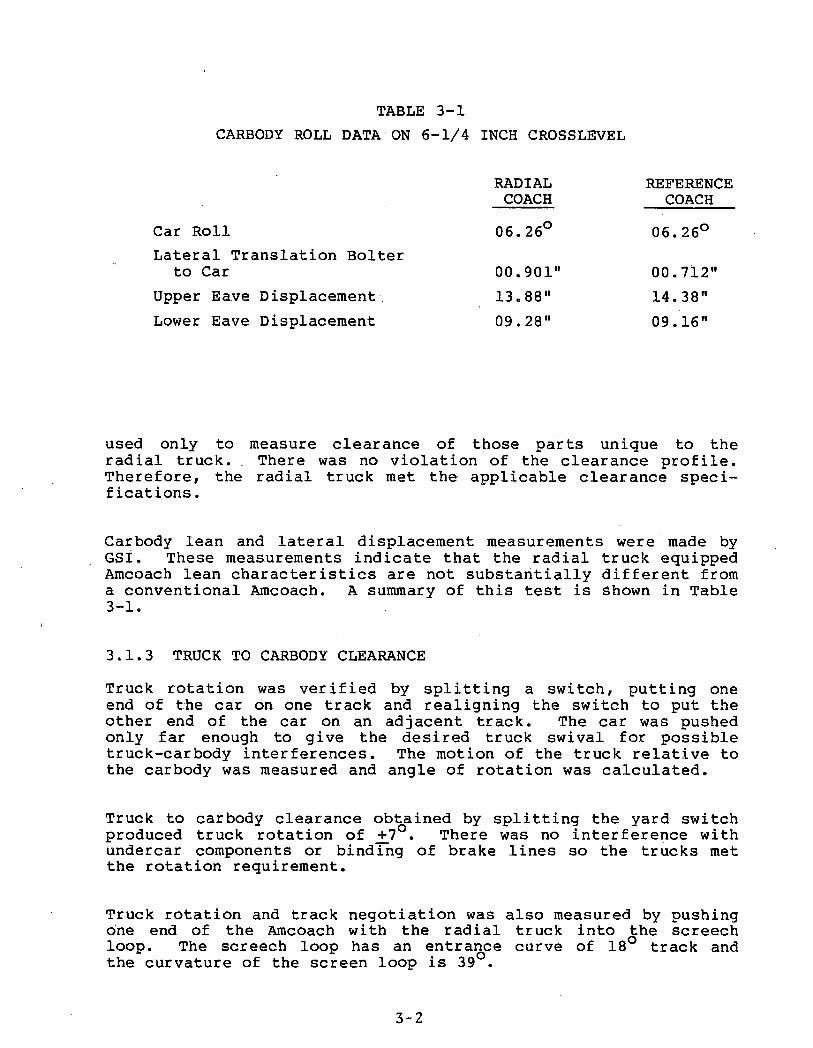
TABLE 3-1CARBODY ROLL DATA ON 6-1/4 INCH CROSSLEVEL
Car RollLateral Translation Bolter
to CarUpper Eave Displacement Lower Eave Displacement
RADIAL REFERENCECOACH COACH06.26° 06.26°
00.901" 00.712"13.88" 14.38"09.28" 09.16"
used only to measure clearance of those parts unique to the radial truck. There was no violation of the clearance profile. Therefore, the radial truck met the applicable clearance specifications .
Carbody lean and lateral displacement measurements were made by GSI. These measurements indicate that the radial truck equipped Amcoach lean characteristics are not substantially different from a conventional Amcoach. A summary of this test is Shown in Table3-1.
3.1.3 TRUCK TO CARBODY CLEARANCETruck rotation was verified by splitting a switch, putting one end of the car on one track and realigning the switch to put the other end of the car on an adjacent track. The car was pushed only far enough to give the desired truck swival for possible truck-carbody interferences. The motion of the truck relative to the carbody was measured and angle of rotation was calculated.
Truck to carbody clearance obtained by splitting the yard switch produced truck rotation of _+7°. There was no interference with undercar components or binding of brake lines so the trucks met the rotation requirement*
Truck rotation and track negotiation was also measured by pushing one end of the Amcoach with the radial truck into the screech loop. The screech loop has an entrance curve of 18° track and the curvature of the screen loop is 39°.
3-2

The Amcoach must negotiate a 23° curve. The minimum truck rotation for the Amcoach carbody geometry is +7° for +23° curves. The test confirmed that the radial truck could rotate sufficiently and negotiate the 23° curve.
3.1.4 SUSPENSION SYSTEM CENTERINGThe car, equipped with radial trucks, was pushed back and forth on level, tangent track. At each end of travel the relative lateral position of the truck and carbody was measured by TTC personnel. The draft specification stated that the truck was required to be laterally centered with respect to the carbody, +0.125 inches was acceptable.
Table 3-2 contains data from this test. and R^ were measurements made from the left and right side of the truck near Axle 1 to the Amcoach body. A similar point was measured on L 2 and R2 . Axle 1 and Axle 2 are on the B-end truck. The measurements L, and L2 were averaged to derive lateral truck motion for the left side of the B-truck.
The right and left sides of each truck are rigidly tied together so the motion of each side of the truck must be identical. Therefore, the excessive motion of the B-truck right side appears to be in error. On this basis the right and left side measurements of the A-truck are within the error of measurement of 1/32", and the truck centering appears to be within the lateral centering of ^0.125" established by the test plan.
3.1.5 HANDBRAKE TESTThe handbrake test was to determine the ability of the braking equipment installed on the radial truck to prevent the coach from rolling on a five percent grade. The disc/tread braking equipment supplied by New York Air Brake is activated by an air over hydraulic system. The handbrake consists of a valve rotated 90° to activate or release. There is no operator adjustment of braking force.
There is not a five percent grade track available at TTC. Therefore, a two and one-half percent grade track in front of the Central Services Building (CSB) was used. Two Amcoaches were ballasted with 10,000 pounds of lead. The handbrake of just the radial truck equipped coach were used to hold both coaches.
The handbrake held the radial truck equipped Amcoach and the reference coach, each ballasted with 10,000 pounds, thereby meeting the specification.
3-3

TABLE 3-2CENTERING TEST DATA
Reading L1RAW
L2LATERALR1
TRUCKR2
MOTION DATA L3 L4 R3 R4
1 22.938 24.875 22.063 24.000 25.025 23.375 23.750 22.1252 22.813 24.750 22.188 24.063 25.063 23.125 23.813 22.1883 22.938 24.875 22.125 23.875 25.188 23,188 23.750 22.1254 22.813 24.750 22.813 24.125 25.250 23.188 23.875 22.1885 22.875 24.875 22.125 23.938 25.250 23.188 23.875 22.188
TRUCK LATERAL MOTIONB-Truck B-Truck .A-Truck A-TruckLeft Right Left Right
1 23.907 23.032 24.200 22.9382 23.782 23.126 24.094 23.0013 23.901 23.000 24.188 22.9384 23.782 23.469 24.219 23.0325 23.875 23.032 24.219 23.032
LateralMotion .125 .469 .125 .094
±. 063 - ±.235 ±.063 ±.047
B-Truck Right LateralMotion ExcludingReading 4 .126
±.063
3-4

The equalization test determined the ability of the truck to distribute the weight of the carbody and truck to the eight wheels in uneven track conditions.
3 . 1 . 6 EQUALIZATION TEST
All wheels were placed on load cells and the load on each wheel was measured. Each wheel was raised individually by means of jacks and load distribution was measured. The load at the wheels was equally distributed within 9.5 percent at an unbalance of 1 inch and within 18.5 percent at an unbalance of 2 inches.
3.1.7 LEVELING SYSTEM TESTDuring initial installation of the radial trucks under Amcoach car number 21091, the leveling system caused the carbody to oscillate with a three to ten second period. The air bag on one side would inflate then deflate again so that the coach continued to rock as the air bags alternately inflated and deflated.
In addition to the initial leveling problems, test runs showed that there were other problems with the carbody leveling system. As the car negotiated high banked curves, the carbody leaned from 6 to 10 degrees and was very slow to recover. In the early tests the leaning exceeded the limits of travel allowed for by the leveling system and broke the leveling valve linkages. To evaluate this problem, a test was made on various spirals and high banked curves. The data from this test were provided to GSI to aid them in evaluating the carbody lean problem and develop modifications to the carbody leveling system.
To reduce the lean problem GSI changed the bidirectional check valves and modified the leveling valves to reduce the delay time. These changes did not totally eliminate the lean problem but improvements were adequate to allow the test to be conducted.
The results of the leveling system tests were used to modify their airbag suspension system. After the system response was altered to prevent damage to the system and prevent oscillations no further data from this test were reduced and no data are included in this report.
3.1.8 AXLE ALIGNMENTThe shakedown test showed that both trucks on the the radial truck test car tended to run flanged toward the right rail when the A-end truck was leading. The right bias occurred whether the
3 -5

coach was in buff or draft. A review of this problem indicated that the steering deficiency was caused by one or more of the following:
• Unbalanced weight distribution• Unequal wheel size• Axle misalignment• Coupler misalignments
Tests were made to determine which, if any, of the suspected causes produced the steering defect. To check for problems caused by unequal weight distribution, the ballast in the radial coach was shifted from the left side to the right side of the coach. Over shifting the ballast in the radial coach and reversing position of the radial truck equipped coach and the reference coach produced no change in running characteristics.
To confirm that the wheels on each axle were the same diameter they were checked on the Hegenscheigt wheel truing machine. It showed that the maximum variation was 0.020 inches against the specification of 0.050 inches. Although the wheels were the same diameter, their profile did not match that specified by GSI because they provided the wrong truing template. The wheels were retrued to the correct profile. This improved the performance but the truck continued to run with a right bias.
Mechanical measurements produced no noticeable difference in dimensions, but TTC personnel proposed an optical measurement technique developed by British Railways that could detect small misalignments. This technique produced data that indicated the A-truck was misaligned enough to cause the steering problem while the B-truck was very nearly perfectly aligned. The chevron primary springs were shimmed to align the axles. Axle alignment was remeasured each time major work was done on the radial truck. Reference coach axle alignment was also measured.
The results of the running test indicated that the axles must be aligned very carefully to obtain proper steering. These tests show that the axles must be aligned within 1.5 milliradians to achieve acceptable steering of the radial trucks.
3 -6

3 .2 SHAKEDOWN TEST
3.2.1 PURPOSEThe shakedown test series was designed to allow the truck manufacturer to make adjustments to tune the radial truck. The series also provided a checkout of instrumentation and test procedures.Shakedown testing was scheduled to duplicate the test plan. It involved testing on the Railroad Test Track (RTT), Train Dynamics Track (TDT), the Facility for Accelerated Service Testing Track (FAST), and the Balloon Loop.
3.2.2 TEST SEQUENCEShakedown testing was conducted as described below:
Day 1: Verify instrumentation and conduct high speed stability runs up to 120 mph.
Day 2: High speed stability runs with longitudinal dampers removed.
Day 3: Curving runs on TDT and Balloon Loop.Day 4: Curving tests on FAST Track.Day 5: Install "soft” longitudirial/lateral
primary spring suspension sandwiches.Day 6: Data analysis and axle alignment mea
surement .Day 7: Balloon Loop curving data and high speed
stability on RTT to 105 mph.
3.2.3 TRACK MAPPINGAutomatic Location Detector (ALD) targets were placed on the tracks used for the radial truck testing: the RTT, TDT, FAST andthe Balloon Loop. ALD targets provide location information which can be related to track conditions and items of interest around the test zones.
The targets were placed at the entrance and exit of spirals, at switch locations, and at every 5000 feet around the track. Identifier patterns were placed every 10,000 feet on the RTT. Table3-3 lists locations of crosslevel and degree of curvature for the test zones used in this test.
3 -7

TABLE 3-3TTC CURVE CRITERIA
TRACKDEGREE OF CURVATURE
SUPERELEVATIONINCHES
STARTLOCATION
ENDLOCATION
SPEEDMPH
3" UNDER BALANCE
SPEEDMPH
BALANCE
SPEEDMPH
3" OVER BALANCE
RTT 0° 50' R 5.95 R55+30 R105+29 71 101 124R191+19 R329+10R397+53 R466+52
0° 50' L R515+39 R530+39RTT 0° 50' R ' 5.95 R543+46 R702+46 71 101 124Balloon 7° 30' L 5.4 B3073+90 B3101+65 21 32 40Balloon 5° R 2.7 B3115+28 B3121+83 28 40FAST 5° L 4.0 F1492+49 F1529+22 17 34 45FAST 5° R 4.0 F1537+22 F1547+22 17 34 45FAST 4° L 5.0 F1580+95 F1597+20 33 47FAST 5° L 4.0 F1622+88 F1625+84 17 34 45FAST 3° L 2.0 ' F1653+86 F1675+12 31 49TDT 1° 30' R 3.03 01630+57 D1720+00 29 54 76
3.2.4 SHAKEDOWN TESTThe results for the shakedown test have been combined with results from the other performance tests and are presented in Section 4 as part of the curving and stability reports.
3.3 CUTAWAY BRAKING TEST3.3.1 PURPOSEThe cutaway braking test was performed to determine the single car stopping distance of the disc/tread braking system as installed by New York Air Brake on the radial truck.
The cutaway test was run after the shakedown series. Its purpose was to set the braking rate of the radial truck equipped coach to match the braking rate of a conventional Amcoach.
3.3.2 INSTRUMENTATIONA data collection system was installed on the radial coach to record the necessary parameters for braking rate. An eight channel analog strip chart recorder with two event pens was used to make a permanent record of data. Parameters measured were:
3-8

• Speed with 100-foot pulses superimposed• Slip/slide indication for either A or B
truck or both• Tread brake hydraulic pressure• Disc brake hydraulic pressure• Lead axle tread temperature• Lead axle disc temperature• Train line air pressure• ALD or ground mounted distance markers• One-second time ticks
In addition to the optical temperature transducers, a hand-held pyrometer was used to measure temperature of all disc and treads after the car had stopped to provide a reference for the data collecting optical pyrometer. Distance of the automatic location detector sensor to the nearest distance marker was also measured to provide a zero speed/distance data point.
3.3.3 TEST PROCEDUREThe cutaway test was designed to produce data compatible with the dual brake test program data as reported in DOT-FR-80-22, "Dual Disc/Tread Braking and Reduced Pressure Braking Evaluation Program."For each test the instrumented Amcoach was accelerated to a speed five to ten miles higher than the selected test speed. As instrumented Amcoach approached the test zone the locomotive engineer applied the brakes slightly and activated a remote uncoupling device. The brakes were released and the locomotive accelerated away from the test vehicle. As the test vehicle entered the test zone the brakes on the coach were applied and the stopping distance was recorded. Target speeds were 60, 80, 100, and 110 mph. The dual brake test also included speeds of 40 and 120 mph but it was decided from previous experience that the four target speeds provide enough information to determine if the brakes being tested adequately fit the braking profile curve. Initially, the tests were to be run at full service reduction, one-half full service reduction, and emergency service braking rates; however, difficulties in setting brake rates allowed only full service and emergency reductions. Experience in the dual brake program indicates that one-half service braking follows full service braking and that this test only verifies the braking rate.
3-9

The test zone was on the Railroad Test Track (RTT) at the Transportation Test Center between stations R14.5 to R25.5. Warning automatic location detector markers were placed 1000 feet and 200 feet before the test zone. ALD markers were placed every 50 feet for the first 1000 feet of the test zone. The track was measured and marked every 100 feet throughout the 11,000 foot test zone. Additional braking tests were run by TTC and New York Air Brake after the attachment fitting of the braking system was rebuilt in January 1981. The original braking system had brake proportioning of 60/40 disc/tread. Because of heat cracking of the single discs the proportioning was changed to 50/50 to reduce thermal load on the disc.
The braking curves for the 60/40 disc/tread tests are shown in Figure 3-1 for full service and in Figure 3-2 for emergency braking .
Temperature and raw speed/distance/time data are given in Table3-4 for full service braking and Table 3-5 for emergency braking .
To reduce the thermal load carried by the single disc, the ratios were changed to 50/50.
3.4 CONCEPT DEMONSTRATION AND PERFORMANCE3.4.1 PURPOSEThe concept demonstration was envisioned as an in-depth test of the final truck configuration developed during shakedown testing. This test used the same test procedures used in the shake- down test but included higher speeds.
The performance test sequence included ride quality, component failure and additional repeat testing of the runs in the concept demonstration.
Because of difficulties in configuring the truck during shake- down the concept demonstration tests and performance tests were combined and the scope of testing was reduced.3.4.2 ACTUAL TEST SEQUENCEThe concept demonstration and performance testing sequences were combined. In addition, only one day of testing on the FAST track was allowed because of the possibility of excessive wear and rail forces that the radial truck test consist might impose upon the
3-10
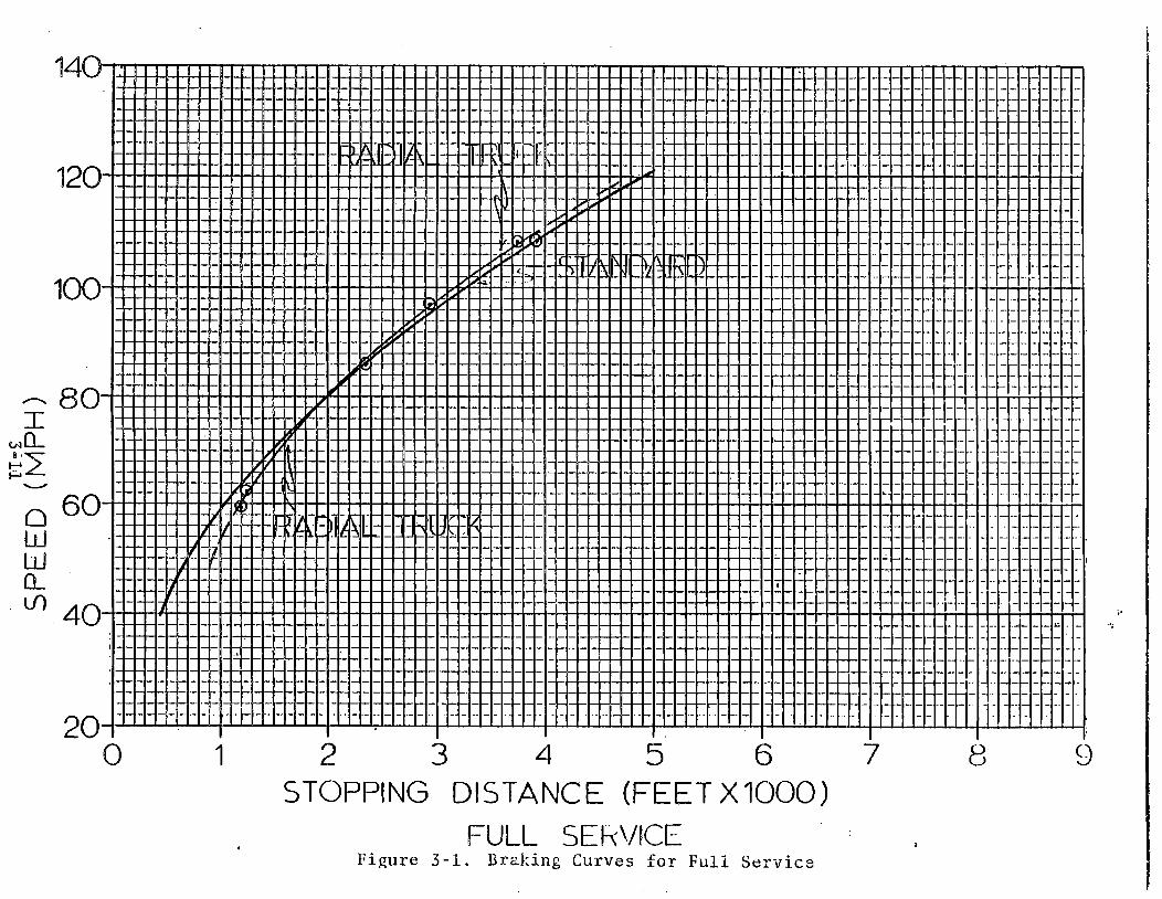
STOPPING DISTANCE (FEET X 1000)FULL SERVICE
Figure 3-1. Braking Curves for Full Service

STOPPING DISTANCE (FEET X 1000)EMERGENCY SEIM EFigure 3-2, Braking Curves for Emergency Service i

TABLE 3 - 4
FULL SERVICE BRAKING DATA*
Car No./Manufacturer: 21091/NYABBrake Service: Full ServiceDisc/Tread Ratio: 60/40_______
Run No. Speed: Speed, TLP TPD-j TPDj DISTn DIST„ DIST D.TEMP T.TEMP TINS DTEMP, dtemph TEMPn TTEMPn TTEHPn TEMPV92701 59.5 59.0 in 54 57 254 1450 1196 230 220 25.3 220 200 +20 120 160 -40
DBCP 635 650 655 660TBCP 430 430 430 430
92702 108.5 107 109.5 53 56.5 513 4263 3750 610 265 45.8 410 405 +5 220 180 +40DBCP ? 655 680 695 700TBCP 435 435 440 430 450
92703 86 84.5 110 53.5 56.5 993 3346 2353 305 240 36.3 350 240 +90 210 180 +30*DBCP 650 670 685 695 695•TBCP 440 455 460 460 460
92704 97 95.8 112 53.5 58.S 1088 4025 2937 260* 260 39.8 - - 480 - 230 190 +400BCF 655 680 695 710 710TBCP 450 450 460 450 460
92709 62.5 61.5 111 54.5 56.5 822 2074 1252 255 235 25.0 240 240 0 210 170 +40DBCP 660 675 680 680TBCP 430 . 450 450 450
92710 108.5 107.5 110 56.5 53.5 1089 5020 3931 445 280 471 360 350 10 230 210 +20DBCP 660 680 695 710 720TBCE 440 450 460 460 460
•"Zero* wrong
TABLE 3-5
EMERGENCY SERVICE BRAKING DATA*
Car No./Manufacturer: 21091/NYAB_____Brake Service: EmergencyDisc/Tread Ratio: 60/40
Run No* Speed: Speed, TLP TPD: TPD<| DISTf) DISTg DIST D.TEMP T.TEMP TIMS DTEMP, dtemp„ TEMPn TTEMPn TTEMPn TEMPV92705 81.5 81 112 ATM - 1161 2862 1701 380 250 26.9 320 380 -60 220 190 +30
DBCP 840 850 870 870TBCP 570 570 570 -
92706 108 107 111 ATM _ 553 3631 3078 635 310 38.0 480 520 -40 260 230 +30DBCP 835 855 880 890 890TBCP “ “ 560 560
92707 61 60 Ill ATM 325 1277 952 33S 230 19.7 290 340 -50 210 190 +20DBCP 840 850 860TBCP 570 570 570
92708 95 94 111 ATM _ 1960 4328 2368 305 270 32.0 290 400 -110 250 205 +45D.3CP 835 840 860 870 870TE1CP 560 560 570 570 570
92711 60.5 59.5 111 ATM _ 1566 2535 969 370 240 20.1 240 300 -60 210 160 +50DBCP 820 830 830TBCP 560 560 560
92712 107. S 106 109 ATM 547 3633 3086 570 280 37.7 410 480 -70 240 220 +20DBCP 340 855 875 880 890TBCP 560 560 560 560 560
*Units for: Speed - mph Tread Temp - °FDist - feet TimeDisc Temp - °F
3-13
sec

track. Track speeds were limited to 45 mph for the same reason. Maximum speeds were limited because the available locomotive was not running at rated power during the test time. The actual run sequence was:
Day 1: Performance curving and brake interaction on RTT, speeds to 120 mph CW direction.
Day 2: Finished performance curving and brake interaction on RTT, speeds to 120 mph CCW direction.
Day 3: Started failed airbag tests.Day 4: Completed failed airbag tests.Day 5: Curving, braking interaction on FAST.Day 6: Data reduction.Day 7: Ride quality 60, 90, 110 mph on RTT. Both
directions and consist interaction.Day 8: Failed crosslink test to 120 mph. Carbody
lean test.
No damper failure test was run since dampers were not used on the final configuration.
3.4.3 INSTRUMENTATIONThe onboard instrumentation for the concept demonstration test is described in Section 2.2. During the FAST testing, in addition to the onboard instrumentation, an instrumented rail section was used to measure lateral and vertical forces on the high rail. The instrumentation was located in section 7 of FAST in the reverse 5° curve. The wayside instrumented rail site was installed for previous tests by TTC personnel. Details on the gaging and results are shown in a separate report published by TTC.
3.4.4 TEST RESULTSThe results from the concept demonstration are described in Section 4.
3-14

3 .5 RIDE QUALITY TEST
3.5.1 PURPOSEThe ride quality test was designed to give comparative ride quality data between the Amcoach equipped with GSI radial trucks and a standard Amcoach equipped with Pioneer III trucks.
3.5.2 TEST SEQUENCERide quality measurements were taken as the last part of performance testing. Additional ride quality tests were to be run at 40,000 miles and 80,000 miles of the life test. Because of the instability problems encountered due to premature wheel wear the life test II sequence was terminated after a little more than21,000 miles on the wheel profiles. The radial truck suspension was altered by installing stiffer longitudinal sandwiches in the primary spring system.
Stability, curving performance, truck frame strains and ride quality testing was conducted by TTC personnel with ENSCO personnel observing. Additional ride quality testing was planned after20,000 miles of life testing with the stiffer sandwiches. Again wheel wear caused truck instability at 14,346 miles. The radial truck life test was again terminated after a final ride quality test sequence was performed by TTC personnel.
3.5.3 TEST PROCEDURESRide quality parameters along with all radial truck test measurements were measured and recorded using the T-7 data acquisition system. The test measurements for ride quality were vertical and lateral carbody accelerations of the radial truck equipped Amcoach, longitudinal motion of the A-end radial truck axles and vertical and lateral carbody accelerations of the reference Amcoach. These measurements along with speed and automatic location detector channels were recorded by the T-7 data system on an analog tape recorder for use by TTC in their ride quality data reduction. The consist was run at speeds of 60, 90 and 110 mph around the RTT clockwise and counterclockwise. The locomotive was then moved to the other end of the consist and coupled to the buffer car. The consist was pulled clockwise and counterclockwise around the RTT at 60, 80 and 110 mph.
3.5.4 RIDE QUALITY DATA ANALYSISThe ride quality data produced by the radial test car and the reference car was reduced by the TTC computer facility and results analyzed by ENSCO to develop a comparison of the car equipped with the radial truck to the car equipped with standard Pioneer III trucks. The results of the analysis is shown in
3 -1 5

TABLE 3-6COMPARISON OF RADIAL TRUCK EQUIPPED CAR AND
CAR EQUIPPED WITH PIONEER III TRUCKS IRadial Coach Reference Coach
Carbody Acceleration Carbody AccelerationA End of 21091 A End of 21018
Speed Vertical Lateral Vertical Lateral60 MPH
Standard Deviation .015 .042 .015 .03995% of value .030 .074 .030 .06499% of value .041 .092 .039 .074
90 MPHStandard Deviation .017 .026 .021 .02795% of value .034 .052 .043 . 05299% of value .048 .070 .058 .069
110 MPHStandard Deviation .023 .029 .0303 .02895% of value .046 .058 .059 .05599% of value .067 .079 .080 .075
Table 3-6. This table shows the lateral and vertical accelerations from the accelerometers located at the end of Amcoach 21091 (the radial test car) and Amcoach car 21018 (used as the reference car). The data selected for this comparison were data taken from the test run on the TTC at speeds of 60, 90 and 110 miles per hour. The table shows both vertical and lateral acceleration data. The summary of results shown in Table 3-7 give standard deviation of the carbody acceleration levels and 95 and 99 percent values of the normalized data based on removing the mean values. These data show that at 110 mph the vertical ride of the Amcoach car equipped with the radial trucks was slightly better than the other Amcoach, however, at 60 mph the lateral acceleration on the reference Amcoach was lower than from the coach with radial trucks.
3-16

3 .6 LIFE TEST
3.6.1 PURPOSE AND PLANNED SEQUENCELife testing was planned to allow the radial truck to experience as many miles as possible in the shortest length of time.
The radial truck equipped Amcoach and the reference Amcoach were placed in an AEM-7 consist with the intention that they would remain for a total of 100,000 miles including performance testing mileage. The AEM-7 tests involved running around the RTT 16 hours per day. Consist speeds and stop times were set to follow a New York City to Washington northeast corridor profile. Running speeds were determined by an ENSCO designed and built "Profile Simulator" originally used in the life test portion of the Dual Brake Test. Car positions and directions were varied throughout the test.
The truck components were inspected daily and tread profiles taken every 10,000 miles. At 60,000 (20,000 performance and40,000 life) high speed stability and ride quality were to be measured using a portable data acquisition system. Ride quality and stability tests were run again at 100,000 total miles. This assumed that 20,000 miles of test were run in performance testing; only 3,397 were actually run in performance tests.
3.6.2 ACTUAL LIFE TESTSThe radial truck equipped Amcoach test was stopped the second time at 21,000 (life test) miles because of excessive wheel wear which caused the radial truck to become unstable. No ride quality testing was performed prior to this stopping point in the test, but wheel profiles were taken.
GSI installed stiffer longitudinal primary suspension sandwiches in the radial truck. High speed stability testing with the old wheel profiles and stiffer sandwiches indicated instability at 105 mph. It was estimated that the stiffer sandwiches increased stable speed by 30 mph. Curving, stability, ride quality and truck frame structural data were measured by TTC. A list of test measurements is included in Table 3-7.
The test was planned to run for an additional 20,000 miles followed by run ride quality testing to measure truck performance deterioration; however, truck testing was terminated after 14,346 additional miles due to truck instability caused by wheel wear. Ride quality testing was conducted by TTC just prior to test
3-17

TABLE 3-7DATA CHANNELS FOR STIFF SANDWICH TEST
1. Longitudinal Motion, Frame to Journal, A-Radial Truck Lead Axlet, Left
2. Longitudinal Motion, Frame to Journal, A-Radial Truck Lead Axlei, Right
3. Longitudinal Motion, Frame to Journal, A-Radial Truck Trailing Axles, Left
4. Longitudinal Motion, Frame to Journal, A-Radial Truck Trailing Axle, Right5. Longitudinal Motion, Frame to Journal, A-Reference Truck, Lead Axle, Left
6. Longitudinal Motion, Frame to Journal, A-Reference Truck, Lead Axle, Right
7. Longitudinal Motion, Frame to Journal, A-Reference Truck, Trailing Axle, Left
8. Longitudinal Motion, Frame to Journal, A- Reference Truck, Trailing Axle, Right
9. Lateral Motion, Frame to Journal, A-RadialTruck, Lead Axle
10. Lateral Motion, Upper Box to Journal, A-Radial Truck, Lead Axle
11. Lateral Motion, Frame to Journal, A-RadialTruck, Trailing Axle
12. Lateral Motion, Uppper Box to Journal, A-Radial Truck, Trailing Axle
13 Truck Swivel, A-Radial Truck14. Truck Swivel, B-Radial Truck15. Truck Swivel, A-Reference Truck16. Vertical Carbody Acceleration, Radial Coach
A-End17. Lateral Carbody Acceleration, Radial Coach A-
End18. Vertical Carbody Acceleration, Reference
Coach A-End19. Lateral Carbody Acceleration, Reference Coach
A-End20. Longitudinal Force in Crosslink, A-End Radial
Coach21. Longitudinal Force in Crosslink, A-End Radial
Coach22. Radial Truck Frame Strain23. Radial Truck Frame Strain24. Radial Truck Frame Strain25. Radial Truck Frame Strain26. Speed27. Distance28. Automatic Location Detector
3-18

termination. One additional life test was run with even stiffer longitudinal primary suspension sandwiches and was terminated after 5 , 3 2 2 miles because test funds were exhausted.
3.7 FATIGUE TESTIt was planned to conduct fatigue tests at GSI facilities. The purpose was to determine the suitability of the truck frame for long term inter-city service.
Since observed strain levels from TTC running tests were very low and running tests in revenue service on a similar design prototype truck were being conducted, it was decided to eliminate fatigue testing from the test program.
Additional strain gage channels were added to the frame on the stiffer sandwich tests to confirm the low strain levels and provide additional data.
3-19

4 .0 TEST RESULTS
4.1 INTRODUCTIONThe results of these tests on the radial trucks indicate that the curving performance was excellent but the stability was unacceptable. The stability was judged to be marginally acceptable during the performance test but it deteriorated rapidly during the life test series. The source of the instability was related to wheel wear. A hollow developed near the center of the wheel tread, increasing the effective conicity (inverse to the wheel taper ratio taking into account the rail head taper at the point of contact) so that the critical speed dropped below the maximum test speed (120 mph). This result indicated that the truck, as configured for the first series of tests, did not have sufficient margin of stability.
The performance and first two life test results show that the radial trucks operated with minimal flange contact. While the flanges on the reference car truck showed considerable flange wear in 10,000 miles of operation, the radial truck wheels showed no flange wear. Other data indicates that the wheels on the radial truck ran consistently with very small angles of attack. These characteristics are major points in favor of the radial concepts but at the same time the good curving performance may have contributed to the tread wear. The TTC track has a very consistent gage so that when combined with the excellent curving performance the wheels ran on only a narrow band of the wheel tread. Therefore, all of the wheel wear was concentrated in one region of the tread. Ideally there would be uniform wear, but in this case it was concentrated to a narrow surface area and a hollow was worn in the tread contour. The trucks allowed some synchronized axle oscillations as the axles are cross tied together and, although these oscillations are relatively small in amplitude when the wheels are new, this appeared to result in wheel tread wear which increased the amplitude of the oscillations to and correspondingly increased tread wear. The mode of the axle oscillation is primarily in pure yaw, causing longitudinal slippage at the contact point on the tread. This oscillating process in too few miles (10-20,000 miles) deteriorates the ,stability to the point that the maximum operating speed (120 mph) must be reduced to avoid serious hunting conditions which could lead to derailment.
4.2 SHOP TESTSSince the results of the shop tests are much clearer when presented along with the test description, the shop test results are located in Section 3 at the end of the description of each test.
4-1

4.3 CUTAWAY BRAKING TESTSThe results for the cutaway braking test are combined with the description of the test and can be found in Section 3.
4.4 SHAKEDOWN TESTThe results from the shakedown test are combined with results of the other performance tests. These results are described in the following sections.
4.5 TRUCK PERFORMANCESince the performance of any truck is a trade off between achieving good curving and maintaining adequate stability over the range of operating speeds for a reasonable number of service miles, the truck performance is presented in three sections. The curving report in Section 4.5.1 describes the results from both the shakedown and the combined concept demonstration/performance test. This section presents the measurements of axle alignment and the angle-of-attack which show how well the truck negotiated the various curves at a wide range of speeds. Section 4.5.2 describes the truck stability and Section 4.7 summarizes the results of the life test. The detailed results of the life test will be reported in a separate report published by TTC.
In addition to these sections, Sections 4.8, 4.9, 4.10, 4.11, and 4.12 describe damage to trucJt components which occurred during the life test. Detailed reports on the damage will be included in the TTC report of the life test.
4.5.1 CURVE NEGOTIATIONThe capability of negotiating curved sections of track was determined by monitoring the alignment between the axles and the angle-of-attack of the wheels.
4.5.1.1 Angular Alignment ResultsThe following set of figures show results from tests run on PAST (3°, 4°, and 5°) the Balloon Loop (5° and 7.5° curves) and the TDT (1-1/2° curve). Figure 4-1 shows data for the axle alignment in relation to the truck frame, and axle-to-axle angles in relation to each other. These data were obtained by analysis of the radial truck from repeated tests on 3, 4, 5 and 7.5 degree curves. In this figure the alignment results are plotted against the operating speed.
4-2

ICO
COliJUJo :e )IdQ
mUJ
<3
.0
.9
.8
.6
.5
A
.3
.2
AXLE ALIGNMENT VS SPEED^ 1 1 ! ! 5— 8 8 1— r l i i i i r i — i— —
2—>°
—A— i— r—i i—i | i—*—i—i—i—i—i— i— r~
BALANCE SPEED
7.5° (o FOR CURVESs
i►
<►*
< >
♦ ■■
> o<>
O □ B o • ( D •
Z5>o ■ • r ~
]
—1_1_1_!_1__1__i__1__1_ __1__1__1_1__1_1. .1. .1__1__ ____1__1__1_I__1__i__i—i_i__i_i_i i i
o
o
20cw ccwO ♦ 7.5°□ ■ 5° RHA ▲ 5° LHO « 4° LHO • 3° LH
30
S P E E D (M P H )
40 50
Figure 4-1. Summary of Results for Axle/Axle Alignment on Leading Radial Truck When Tested on 3,4, 5 and 7.5 Degree Curves

Figure 4-2 shows the same axle to axle angle data as in Figure4-1 except the alignment data have been plotted against the cant deficiency which corresponds to the operating speed for each particular curve.
The axle alignment data from the leading radial truck is presented in another form in Figure 4-3 and 4-4. Perfect radial alignment exists if each of the axles is aligned perpendicular to the track at the wheel location.
Based on the geometry data for each of the TTC curves the ideal axle alignments are shown by Figure 4-5 and the associated Table4-1. In Figure 4-3 and 4-4 the alignment achieved by the radial truck has been compared to the ideal angles as shown in Table4-1. These graphs show the axle to axle angular alignment plotted as a percentage of the ideal angle for the particular test curve.
The same set of figures show angular alignment for the trailing radial truck and are shown in Figures 4-6, 4-7, 4-8, and 4-9.The axle to axle alignment data plotted against cant deficiency which corresponds to Figure 4-2 is shown in Figure 4-7 and the set of alignment figures showing the alignment of the axles on the trailing truck plotted as a percentage of the ideal radial alignments are shown in Figure 4-8 and 4-9.
4.5.1.2 Alignment ResultsIn this report all angular alignment data are shown as having a positive sign. The actual angular alignment test data have both positive and negative values since the data were obtained from tests run in both right and left hand curves and for both clockwise and counterclockwise operations. In all observed cases (except for data from the 1.5 degree TDT curve), the angular alignment of both the leading and trailing axle was in the proper direction for a well behaved radial truck (see Figure 4-10 and4-11). Therefore, all of the data has been converted to have a positive sign so that the results can be combined and compared.
The angular alignment data show that at 10 mph the alignment of the leading and trailing axle relative to the truck frame was approximately 0.15 degree for the 3, 4 and 5 degree curves. Both the leading and trailing axles rotated to become more radial as the speed increased. The angle of the leading axle (relative to
4-4

AN
GL
ES
(D
EG
RE
ES
)
AXLE ALIGNMENT VS CANT DEFICENCY—1—1—1—1— ---1---1---1---1--- —i i—i—r~\ i i i i 1 1 ~l 1 T i l l r i i i i—i—i—i
♦ <[>♦
o ! □0o
O O ' A £ o»
mn% d j A
O'
_1_!_1_I__l_!_1__1__i_i_i_i__1_1_1_1_ _ j_i_11 _1__1_1_1__i_i_i_i__i_i_i_i_
.9
.8
.7
.6
.5
A
.3
.2
.1
.0
. 0
4 -3cw ccwo • 3°o « 40
A ▲ 5° LH□ ■ 5° RHO ♦ 7.5°
- 2 - 1 0 1 2 3
CANT D EFIC IENCY ( INCHES)
Figure 4-2. Summary of Results for Axle-to-Axle Anglevs. Cant Deficiency for Lead Radial Truck When Tested on 3, 4, 5 and 7.5 Degree Curves
O

% O
F ID
EA
L A
XLE
TO
AX
LE
AN
GU
LAR
A
LIG
NM
EN
T 220
200
180
160
140
120
1 0 0
80
60
40
20
0
A X L E A L I G N M E N T V S S P E E Di i i 1 1 1 1 1 1 i i i i i i i i i i
}°
1Gi i i i i i | i i i i i i i i i
BALANCE SPEED4 o FOR FAST CURVES
/\
□/
, <><> •C
□ m ^
<» < ? \ ■ ♦O O
A < A C ' C
) a■ ■
)
__i__i__i__i__i i i i__i__ __i__i__i__i__i__i__i__i__i__ __ __1__ __ __1__1__1__1__1__ __i__i__i__i i. i__i__i i
O
10 20 30 40ccw cw SPEED (MPH)• o 7.5°o 5° RH Figure 4-3. Summary Results of Axle Alignment of Leading
Truck on Radial Truck Car for Tests on 3, 4, 5▲ A 5° LH and 7.5 Degree Curves■ □ 4 ° LH♦ O 3° LH

9/o O
F TH
ER
OE
T1C
AL
AX
LE
/AX
LE
AN
GLE
A
XLE
A
LIG
NM
EN
Tf
200
180
160
140
120
1 0 0
80
60
40
20
0
220AXLE ALIGNMENT VS CAN DEFICENCY
— 1— 1— 1— 1— ---- 1---- 1---- 1-----1— ---- 1---- 1---- 1---- 1---- — 1— 1— 1— 1— ~ I -----1---- 1— 1----- — i— i— i— i— — 1— I— 1— 1— ~ I — 1— 1— |—
O
Q O
♦
o
D 2 < > A
♦O o !
A C A •□ □
O t A\ 7
i i___1___1----- __ 1___1___1___ l__ ___1___1___1___1__ __ 1__LI__ 1___1___ __ i___i___i___i___ ___1___1___1___1__ _ J ___l__ l___i__ _ j___I___i___ l__
-4CCW cw
- 3
• o 3°« o 4° LH▲ A 5° LH■ □ 5° RH
♦ O 7.5° LH
-2 - 1 0 I
C A N T D E F IC IE N C Y ( IN C H E S )
Figure 4-4. Summary Results of Axle-to-Axle Alignment as a Percentage of an Ideal Radial Alignment for 3, 4, 5 and 7.5 Degree Curves for CE and CCW Tests o n :FAST

°T
t
3<*? . C
CD
lV*
•3 ? —
ClCDm

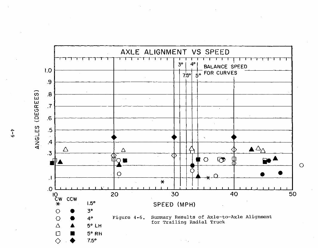
AN
GL
ES
(D
EG
RE
ES
AXLE ALIGNMENT VS SPEED~ 1— 1— 1— 1— !— 1— 1— 1— 1— — 1— 1— 1----1— !— 1— 1— 1----1---- 1
*3— — i— i— i— i— i— |— i— i— i— i— i— i— i— i— r~
B A LA N C E SPEED
7.5° c(Q FOR C U R V E S
.
1
◄► ◄► ◄►
A A < > a a a
*\ S
>
i1
11 O c] A
O
\
L O • •
__1 -1__1__L_1__1 1 !■ 1__*
__i__i__i__i__i__i__ i__i__ i__ __ __ __IT__i__i__ i__ i__i i — i__i__i__i i i i i i
o
! 0cw*-
ccw1.5°
o • 3°o # 4°A ▲ 5® LH□ ■ 5® RH0 ♦ 7.5®
20
Figure 4-6,
30
S P E E D (M P H )
40 50
Summary Results of Axle-to-Axle Alignmentfor Trailing Radial Truck

IHo
COLlILlICCCDLUQ
COLU_ lCDZ<
1 .0
.9
.8
.7
. 6
.5
.4
.3
.2
.1
.0
AXLE/AXLE ALIGNMENT VS CANT DEFICENCY1 I ~|— i — i— i i— r— “ i "i I— r ~ i— i i— i— ~ i — I— I— i— — i— i— i— i— i m — i— ~ n i— i— r *
\l
♦ . ♦ ◄►
A A □ o - ▲ >
O■ ° f i k c D • 1] ▲
■ ■
O
1
/
wn
A * « • • ■
_ i__ i__ i__ i__ __ 1___1___1___1__ __ i___i__ i__ i__3 ° '
__ 1___1__ 1___l___ __i— i__ i__ i— __ 1___1__ 1___1__ ___i___i i i — j— i___i___i _-4cw ccw o • o # A ▲ □ ■ O
-3
345 LH
- 2 - I 0 I
CANT D E F IC IE N C Y ( IN C H E S )
Figure 4-7. Summary of Axle-to-Axle Alignment forTrailing Radial Truck
7

Vo O
F ID
EAL
ANG
LE A
LIG
NM
ENT
2 0 0
180
160
140
1 2 0
1 0 0
80
60
40
w 2 0
0
% OF AXLE ALIGMENT VS SPEED TRAILING RADIAL TRUCK
: i ! i i ! i i i i i i i i i i i i i*3i° 4o
1 1 1 1 !BALANCE
l 1 1 1 l l 1 l I
7 5° fSPEED
5°*
A 0
3O A
□c o o ,
. A < <>1 ■ 1
•1
• A ,
. i i i i i i i_i_i___i_i_i__i__i_i_i_i_i_ ___1_1_1_1_1_ _ i_i_I__i_I_i_l_i i10cwO
ccw♦ 7.5°
20 30SPEED (MPH)
40
□A
■▲
5° RH 5° LH
Figure 4-8. Axle-to-Axle Alignment Radial Truck
for Trailing
O # 4°O 3°
50

200
180
160
140
120
1 0 0
80
60
40
20
0
% OF AXLE ALIGNMENT VS CANT DEFICENCY TRAILING RADIAL TRUCK
i i i i t i l l 1 1 1 1 ! ! ! 1 1 1 1 1 1 1 1 1 i i i i i i 1 i
A A n- A
□ □ O ♦ 1<
» ° <) ~
► ° °▲■ o A " O o 1
• • u <
A
l l l » 1 1 1 1 i i i i - 1 . .1 1 L _ l __ L l_ ]— . i i i i i i i i i - i i i- 3 - 2 - 1 0 1 2 3
CANT DEFICIENCY (INCHES)
• 3° L H# 4 ° L H
5 ° L H5° RH
Figure 4-9. . Summary of Axle-to-Axle Alignment for■ the Trailing Radial Truck
4
▲

Figure 4-10. Geometry for Calculating Truck Angle-of-Attack from Bolster Swival Angle and Curvature

SIGN CONVENTION TURNS TO LEFT
SIGN CONVENTION TURNS TO RIGHT
WHEEL GAGE = 4 ’ 5 1/4M + 2” = 55.25”TRACK GAGE = 4 ’ 5 5/8” = 56.62”MAXIMUM TRUCK ANGLE ON TANGENT :
3 3 , J y C = 1 4Q °FOR 5° CURVE, NOMINAL ANGLE = 1 / 2 100 ■RANGE OF ANGLE = 1.49° ± 0.7° = 0.79°— *-2.19°
1.37” FREElo 37”
10 2” + 10”= 0.70'
NOTE: Numbers in parentheses are instrumentation channels. ^Angles of attack are (+) when attacking rail.
Figure 4-11. Range of Wheel Angle-of-Attack
4-14
PLAY

ATT
ACK
AN
GLE
(D
EG)
.8
.7
.6
.5
.4
.3
.2
.1
0
- !
-.2
TRUCK ANGLES OF ATTACK VS SPEED RADIAL CAR LEAD TRUCK
!— 1— 1— 1— 1 !— 1— 1— 1 i i i i i i i i i ^ i i i i i— i i— 1 1 1— 1 1 1 1 1 1
k □A ______________________________________
A■ *
D
►
■ r * □
m ^ < ^ _________________________________________ :3 d } ° 9 o □ (
> £ & • «
i i i i i i i i i i i i i i i i i i
♦
1 1 1 1 I I 1 1 1 i i i i i i i i i1 1 1 1 1 l 1 1 1 I 1 I 1 1 1 I I I 1 1 1 1 1 1 1 1 1 1 1 1 1 1 1 1 1 1
1 i i i i i____ i_____i____ i____ i____ ____ i____ i____ i____ i____ i____ i____ i____ i____ i____ ____ 1____ 1____ 1____ 1____ 1_____1____ 1____ 1____ L _ ____ i____ i i i i____ i____ i____ i i
10O # 7 .5 °A ▲ 5 ° R H
□ ■ 5 ° L H
O ♦ 4 ° L H
0 # 3 ° L Hcw ccw
20 30
SPEED (MPH)40 50
' Figure 4-12,1. Truck Angle of Attack Results for A-Truck of the.................. ...... ............... - _____ - . ................... ■

>£> I ■
H cn
.8
.7
CD Ui O
LlI—I 4 CD Mz
« . 3i t
< .2i -i -< .
-.2
TRUCK ANGLES OF ATTACK VS SPEED RADIAL CAR TRAILING TRUCK
i i i i i i i i i 1 1 1 1 1 1 1 1 1 i i i i i i i i i 1 1 1 1 1 1 1 1 1
1\
tj4 _«i 3A _ □ 4 ma <q
i i 1 1 i i i l l ? ° " * o<i i I i i i i r' i ► a? m 11 1 1 1 1 1 1 1 1 *t o1 i i i iw i i iw i1 1 1 1 1 I 1 1 1 i i i i i i i i i 1 1 1 1 1 1 1 1 1 1 1 1 1 1 1 1 |
1 l l_1 1 1_1_1_1__i i i _i_i_i_i_i_i_ o_1_1_1_1 1 1_1 1 1 ♦__ i i j... i__ i__ i__ l__ l__
10cwO
ccw♦ 7 .5 °
A A 5° R H
□ ■ 5 ° L HO « 4 ° L HO • 3° LH
20 30
SPEED (MPH)
40 50
Figure 4-13. Truck Angle of Attack Results for the .R-Tt.uck,. Radial.--.Gar...........________
i J Q T-V.

ATTA
CK
ANG
LE (
DEG)
.7
.6
.5
.4
.3
.2
.1
.0
.8
TRUCK ATTACK ANGLES VS SPEED REFERANCE CAR LEAD TRUCK
! i i i i i i i r —i i—i i i i i i i 1 1 1 1 1 1—1—1—I- i—n —i—i—i i—i r ~
◄►-
■ A◄► <► □
Z ? < > <_____A________
>
□9
□[
■ 0 •0 --------------------------©
A I^O A A
f $ ° * o c) o oc
i i i i i i i i i i l i i l 1 i l l 1 1 1 1 1 1 1 1 1 1 1 1 1 1 1 1 1 1i i i i i i i 1 i 1 1 1 1 1 1 1 1 1 1 1 1 1 1 1 1 1 1 1 1 1 1 1 1 1 1 1
_ i__i i—i i__i__i__i__i__ __1__1__1__1__1_1__1__1__1__ __1__1__1__1__1__1__1 1 1 __1__1__1__1__1_1__1__1__1_10cw ccw
* 1.5°O • 3° LHO # 4° LHA ▲ 5° LH□ ■ 5° RH
A . —f r~
20 30SPEED (MPH)
40 50
V. Figure 4-14. Truck Angle of Attack Data for the \ A-Truck Reference Test Car

TABLE 4-1IDEAL AXLE ALIGNMENT DATA
DEGREE OF CURVE
RADIUS(FOOT)
AXLE/AXLE ANGLE FOR IDEAL RADIAL
ALIGNMENT IN DEGREES0° 50' 6876 .0711° 00' 3820 .1283° 00' 1910 . 2554° 00' 1432 .3405° 30' 1146 .425 '7° 30' 764 .638
the truck frame) increased to 0.25 degree at the higher speeds (45-50 mph) while the rear axle (relative to the truck frame) rotated to approximately 0.18 degree at the same high speed operation. These data show that , the axle alignment corresponded with the curves and in each case increased with the speed. The results show that at the respective balance speeds the axle toaxle alignment was related to the curvature. The angleaxles at the balance speeds was as follows:
Degree of Balance Axle/axleCurve Speed Angle3° 31 0.254° 33 0.315° 34 0.37
The largest variation from trends on the axle to axle and axle to truck frame alignment data was observed in the results for the 5 degree right hand curve. The data from this curve appear to be consistently lower than the angles measured for the other similar curved sections. The brush chart records show that this trend was caused by a local perturbation. The truck tended to react to a deviation in this particular curve so that the data from the truck swival and axle angular alignments changed for a short section of the curve body.
The angular alignment data shows that at balance speeds the trucks negotiated the curves with a high percentage of theoretical radial alignment for all curves from the 1.5 degree to the7.5 degree curve. The alignment was generally proportional to
4-18

curvature and the ratio of actual radial alignment to ideal radial alignment did not vary significantly with curvature.
The alignment data shows a consistant trend when the axle-to-axle alignment data are graphed as a function of the cant deficiency as is shown in Figure 4-4.
As previously described, Figures 4-3 and 4-4 show the alignment data for the A-truck (lead) plotted as the percentage of the ideal radial alignment. Figure 4-3 shows the percentage of radial alignment vs speed and Figure 4-4 shows the percentages plotted vs cant deficiency. These plots clearly show that the truck alignment approached the ideal alignment at the higher speeds in an overbalance condition. This is ideal since the best station to station trip time would most likely be run in overbalance on every curve possible.
The test results for the B-truck (trailing) of the radial test car are shown in Figures 4-6 through 4-7.
The axle-to-axle angular alignment data from the B-truck have been compared to the ideal alignment data for each of the test curves as was the data from the A-truck and the results were plotted against speed and cant deficiency. The percentage of ideal axle alignment vs speed is shown in Figure 4-8 and the percentage plotted against cant deficiency is shown in Figure 4-9. The tests showed that a radial truck is very sensitive to axle to frame and axle to axle alignment.
The B-truck data show that the actual alignment expressed as the percentage of ideal alignment remained constant as the speed was increased. Since the results were independent with speed the results were also independent of the cant deficiency. All of the percentage results fell between 40 and 80 percent except for one data point. The data indicate that the axle angular alignment was more nearly radial for the smaller degree curves and was not as completely radial for the 5 and 7.5 degree curves.
4.5.1.3 Truck Anqle-of-AttackThe angle-of-attack for both the A- and B-trucks of the radial test car and the A-truck of the reference test car were computed from the truck swival data and the curving geometry as shown in Figure 4-10. If the truck negotiates the curved section with a zero angle of attack, the truck is aligned perpendicular to the radial line passing through the center of the truck. In this condition, the swivel angle will agree with angle TA in Figure 4-10. The difference between angle TA and the swival angle gives
4-19

the truck angle of attack. The major error in this assumption occurs when the truck is not actually centered on the track gage. The error resulting from this assumption turns out to be very small because the angle is created by the carbody length. When the truck has an angle-of-attack, the maximum error is further reduced because the truck must be closer to the center of the track because of the truck angle.
The truck angle of attack results are shown in Figures 4-12, 4-13, and 4-14. Figure 4-12 shows the attack angle results for the A-truck of the radial car and Figure 4-14 shows similar angle-of-attack data for the A-truck of the reference test car.
The results for the truck angle of attack for the A- and B-truck radial trucks were quite similar. In both cases, the angle of attack decreased with increased speeds. All of the data are closely grouped about a common trend line. The only major difference in the A- and B-truck is that the A-truck attack angles were approximately 0.1 degree greater than the B-truck data. The truck angle-of-attack data for the lead truck of the reference car shown in Figure 4-14 has the same general trend but in this case the results from the different curves are significantly different. The results show a definite order in relationships based on the degree of curvature. The truck angles-of-attack for the 7.5 degree balloon loop curve ran between 0.5 and 0.6 degree while the attack angle for the 1.5 degree curves was less than0.3 degree. In addition, the reference truck angle-of-attack changed by approximately 0.1 degree. The results show that the truck angle for the reference truck was much larger and more dependent on the operating speeds.
4.5.1.4 Wheel Attack AnglesFor the radial trucks, the wheel angle-of-attack is a combination of three factors. The truck angle-of-attack, the axle alignment relative to the truck and the heading of the rail. The truck angle-of-attack and axle angles are both relative to the center of the truck, therefore, the angle of the wheel relative to the rail (wheel angle-of-attack) at the point of contact between the wheel and rail must include the change in heading of the rail for the distance of half the truck length (from the center of the truck to the center of one axle). As with the angular alignment data, the attack angle data have always been displayed as having a positive sign. The attack angles were positive when the wheel was attacking the right rail and negative for attacking the left rail. The angle-of-attack data shown in the following charts and tables was obtained by summing the truck attack data and the angular alignment data as illustrated in Figure 4-10.
4-20
4.5.1.5 Angle-of-Attack Detailed ResultsThe following figures show summaries of the angle-of-attack data. For these figures, the detailed results from the FAST and Balloon Loop tests have been combined to illustrate the truck performance. The four summary figures. Figure 4-15, 4-16, 4-17, and 4-18, show the results from the 5 degree right hand and 5 degree left hand FAST curves. These data show the variation in test results from similar right and left hand curves negotiated at different speeds and in both clockwise and counterclockwise operations. Figures 4-15 and 4-16 show results from both the radial truck and the reference car truck. The data from the leading axle of the radial and reference car for 3, 4, 5 and 7.5 degree curves are all shown in Figure 4-19. Figure 4-16 shows a similar summary of the test results showing the truck angle of attack vs. speed.
Figure 4-15 shows that the radial truck operated with a substantially lower angle-of-attack than the reference truck on both 5 degree left-hand and 5 degree right-hand curves in both CW and CCW tests. Both the radial and reference trucks angles-of-attack decreased slightly with increasing speed. Both show some scatter but the maximum deviation from the trend appears to be less than0.1 degree. At low speeds (10 miles per hour) the lead wheel of the reference truck operated with approximately 0.7 degrees of attack angle while the radial truck negotiated the same 5 degree curve with a 0.3 degree angle-of-attack. At the higher speeds (45 mph) the angle-of-attack of the radial truck decreased to approximately 0.2 degrees. The reference car leading wheel angle-of-attack was 0.6 degrees.
Figure 4-16 and 4-17 shows similar data to Figure 4-15. In these figures, the data from the CCW and CW operations are presented. The figures show that the radial truck displays minor differences in angle-of-attack for the clockwise and counterclockwise tests. To account for this difference, the strip chart of the data was reviewed. The difference developed because of a local distrubance which repeatedly occurred as the truck negotiated the particular section of the curve used for this analysis.
Figure 4-18 shows a least squares fit of the angle-of-attack data for the leading and trailing wheels of the leading truck of each car for a 5 degree curve. This curve set shows that the leading and trailing axle of the radial truck ran at the same angle-of- attack while the angle-of-attack for the lead and trailing axle of the reference truck car is very different. The lead wheels have an angle-of-attack of nearly 0.7 degree while the trailing axle has an angle of nearly 0.25 degree. This difference in the reference truck is caused by the change in the heading of the curved section of track over the wheel base of the truck since the reference truck attack angle is fixed by the rigid primary
4-21

1 . 0
iifc»toto
.9
.8
.7
oLJ .6 Q
ATTACK ANGLES VS SPEED
.5
.4
LlI _ Jo z <
* .3o
S .2H< .1
0
-.2
—i—i—i—i—r—i—i—i—i— l l l i i i 1 i l ' 1 1 1 1 1 l I---1---1— i i i i i i i i i
■ • o /REFERENCE 7RUCK ■
□ ------- ---------- -- _____ ^ ■n M_______________ u i ------ ----------—1_1
W °
__________L_______ ■ 1
•1
# /RADIAL AXLE TRUCK
—_ #
#O O ~ ~
A o o ±
! 1 1 1 1 1 1 I 1 i i i i | i i i i i i i i i i i i i1 1 1 1 1 1 1 1 1 1 1 1 1 1 1 1 1 I i i i i i i i i i 1 I 1 1 1 1 1 I 1
i i_l_■ i i_1_i_i__1_1_1_1_I_1_L_J_1__i_■ » ' i i_i_i_i_—1—1—1—1—1_1_1_1_1_10 2 0 3 0 4 0 5 0
SPEED (M PH )
REF REF RAD RAD Figure 4-15. Angle-of-Attack Results from the ., ■CW CCW CW CCW .................. Leading Axle of the. Radial and . ..o • A ▲ 5 DEGREE RH SECTION 7 Reference Truck from 5 Degree Right
and 5 Decrree Left Hand FAST Curves□ ■ O # 5 DEGREE LH SECTION 3

ATT
ACK
AN
GLE
(D
EG)
.9
.8
.7
. 6
.5
.4
. 3
.2
.1
0
-.1
-.2
1 . 0
ATTACK ANGLES VS SPEED__ . . . ■1 1 \ 1 \ 8 I I I 1 1 1 1 l 1 1 1 1 i i i i i i i 1 1 i i l i i ( 1 1 1
II ■□ ■
■□ □ □
AA
A AA A
Aa
i i i i i i i i i ! 1 1 1 ! ! 1 1 1 i i i i i i i i i 1 1 1 1 1 1 1 1 11 1 1 I 1 1 I I 1 1 1 1 1 1 1 1 1 I i i i i i i i i i 1 I 1 1 1 1 1 1 11
_1_1_1_1_!_1_1_1_1__l_l_1_1_I_1_1_1_1__i_i_i_i_i_i_i—i_i_ —1—1—1—1—1—1—1_1_1_10 20
CC W c w
■ □ R E F T R U C K
A A R A D I A L T R U C K
3 0
SPEED (MPH)4 0 5 0
Figure 4-16. Angle-of-Attack Results from the Leading Axle of the Radial and Reference Truck from the 5 Degree Right Hand and 5 Degree Left Hand FAST Curves

AT
TA
CK
A
NG
LE
(D
EG
)
.9
.8
.7
.6
.5
.4
.3
. 2
.1
0
- . 1
-.2
1 . 0
ATTACK ANGLES VS SPEED1 1 1 1 1 1 i l l i i i i i i i i i i i l l i \ i ^ l 1 1 8 1 1 1 1 1
-
\- i i_____________
• ■£ □ L A
■ " ■□
^ A 5. At]i i i i i i i i i 1 1 1 1 1 1 1 1 1
o1 1 1 1 1 1 1 1 1 1 1 1 1 1 1 |_1—4——1—l—l—i l l i l l I 1 1 1 1 1 1 1 1 1 1 1 1 1 1 1 1 1 1 1 1 l 1 1 1 1 1
■ i_i_i_i_i—i—i—i— ' i_1_1_I_1_1_1_1_ 1 1 1 1 1 1_1_1_1__i_i_i_i_i_i_i_i i10 20
CCW CW■ □ LEAD AXLE
▲ A TRAIL
3 0
SPEED (M PH)
4 0 5 0
Figure 4-17. Angle-of-Attack Results from theLeading Axle of the Radial Truck from 5 Degree Right Hand and 5 Degree Left Hand FAST Curves

AT
TA
CK
A
NG
LE
(D
EG
)
1 . 0
ATTACK ANGLES VS SPEEDI I 1 1 1 1 1 1 I — 1—1—1—1 1 1 1 1 1 — i— i—i—l— l—i—i—l— l——i— i—i i i l i i l—
/LEAD REF*
— __________________i
RADIAL/ (L E A D OR TRAIL)
/ t r a i l REF■ ■
1 1 1 1 1 1 1 1 1 1 1 1 ! 1 1 1 1 1 1 1 1 1 1 ! 1 1 1 1 1 | I I 1 | | II I 1 I 1 1 11 1 1 1 1 1 1 I 1 i 1 1 1 1 1 1 1 1 1 1 1 1 1 1 1 1 1 1 1
1 1 1 1_1_1__1__1__1__ i ' i i i_1__1_l_l__ __1__1_1_1__1__1__1—1— 1— i i_1__l_1_1__l__1__1_2 i ' i i i i i i i » ■ i i i___i___i___i___i___ ___ i___i___i___i___ i___i___i— i— i— — i— i— i— i— i— i— i— i— i—
10 20 30 40 50
SPEED (MPH)
Figure 4-18, Angle-of-Attack Results from the Leading Axle ofthe Radial and Reference Truck from 5 Degree Right Hand and 5 Degree Left Hand FAST Curves

1 . 0
Ifo
ATTACK ANGLES VS SPEED.9
.8
y
i i i i i i i i i —i—i—i—i—i—i i i—i— —i—i—i—i—i—i—i—i—i——i—i—i—i—i—i—i i—i—
/5° REF X^ 5 - : : -___— _____________
l r p * pLd O Q P
p j/ P P a /1LU -5
i - 4
0 ~ J — -------/ 1
U° REF1
* p S
/3° REFl
; p * ______ _ / . ^,11 i o RAD » U ■ Cj ------- --—
.OO A & -------------------- ---- _ A / v /
_______ ■P -2 n.— ,___ _________ _ ------------ Ai—< i ^ / ------- • J-----O ar----------- — - A c t ia
0
__ I
1 1 1 1 1 1 I I I*4° RAD
1 i i i i i i i i
C T " ------- (J ---Ci i i i i i i i i n — • — -i / 1 1 1 1 1 i i iI I ! I 1 1 11 1 1 1 1 l l l l i I 1 1 1 l 1 1 1 1 1 \ j i i i i i i i i
,3° RAD. i
- .2 ■ i_i_i_i_i__i_i_i— i i i i i i_i_i_i_ ■ i i_i__i_i_i_i_i__i_i_i_i_i_i_i_i_i_
RAD RAD10
REF REFCW CCW CW CCWA A P A 5° RH□ ■ 0 A
I_iin
O « 0 A 4°O • 0 A 3°
20 30
SPEED (MPH)40 50
Figure 4-19. Summary of Test Results Showing Angle ofAttack vs Speed for Leading Axle of RadialTruck on 3, 4 and !i Degreee Curves

suspension of the truck. The radial truck allows the axles to adjust to the curvature so both lead and trailing axles can have a favorable attack angle as shown by this figure.
The summary shown in Figure 4-19 shows the angle-of-attack data for the 3, 4, 5 and 7.5 degree curves. This figure shows that the radial truck negotiated all the curves with nearly the same angle-of-attack. The attack angle for the 5 degree curve was slightly higher than the attack angle of the 3 and 4 degree curves but all were within plus or minus 0.15 degrees from the mean for all curves. The angle-of-attack for the lead wheel of the truck on the reference car was also much the same for the 4 and 5 degree curves but the data for the 3 degree curve were significantly lower.
4.5.2 STABILITYThe overall test results indicate that the curving performance of the radial trucks was excellent but the stability was marginal. During the performance tests, the truck was operated at speeds up to 126 mph with acceptable stability but these tests were made while the wheels were still unworn, i.e. less than 3,397 miles on the wheel treads. Axle oscillations were detected during the performance tests but the amplitude of the axle motion was within the safety limits which had been established as being acceptable. With new wheel profiles, the axles experienced oscillations which varied with track location and in some locations the oscillations decreased to almost unperceptable levels while in the other locations a slight motion could be seen.
During the life test, the axle oscillations increased in amplitude and persistance. The running speeds had to be reduced from 120 mph to less than 100 miles per hour because of severe oscillations of the axles and trucks. The life test was stopped at about 21,000 miles.
The wheels were reprofiled and stiffer longitudinal (and lateral) -shear sandwiches (stiffness "D") were installed in the primary springs and a third series of life tests were performed. This life test series was conducted by TTC personnel and will be covered by separate reports issued by the Transportation Test Center. The progress reports on the third series of life tests indicate that the truck ran well while the wheel profiles were still new but that higher amplitude axle oscillations returned after about 10,000 miles of high speed operation on the RTT track. The third life test series was stopped with 14,346 miles on the wheel treads. This was still not an acceptable result. The wheels had worn to the point that the conicity changed enough to cause axle hunting after only 10,000 miles at operating

speeds. This suggests that the wheel wear rate is excessive and that the truck performance is sensitive to wheel wear.
GSI originally prepared three different shear sandwiches for the lower section of the primary suspension. The shear sandwich controls the longitudinal and lateral spring rate of the primary suspension since the longitudinal and lateral rates of the upper section of the journal box are much higher than the shear rates for the shear sandwiches.
In addition to the shear sandwich option, the truck was equipped with dampers between the ends of the axles and the truck frame. The external axle yaw dampers were designed to dampen the axle oscillations if needed for high speed operations.
4.5.2.1 Shakedown/StabilityShakedown tests were run on the firm primary suspension longitudinal shear sandwich with dampers, with firm sandwich and no external axle yaw dampers, and on the softest of the three sandwiches. The spring rates are referenced as follows:
• Softest sandwich stiffness A• Medium sandwich stiffness B• Firm sandwich stiffness C• Stiff sandwich stiffness D• Very stiff sandwich stiffness E
Available during shakedown and performance test
Manufactured later in life tests*
When the wheel profiles were still new the trucks were stable. Speeds of 126 mph were achieved on one section of the RTT. The speed elsewhere on the RTT loop was limited by the locomotive power. Small axle oscillations were observed, but the axle oscillations appeared to be related to particular track conditions at different sections of the RTT. The amplitude of the axle motion in these test sections was less than one degree peak to peak.
Tests were made with the softest shear sandwich (stiffness A) without dampers. No tests were made with the soft sandwich and
*TTC report contains the results of truck spring stiffness test.
4-28

dampers because if the soft sandwiches with dampers proved effective the stiffness would be increased to avoid the requirement for the additional dampers.
The results of the test with "stiffness A" shear sandwiches and no damper showed that this configuration did not have adequate stiffness. The test speed was increased in steps up to 115 mph but at this point the amplitude of the axle oscillation approached the safety limit criteria so the tests were discontinued. With these shear sandwiches, the amplitude of the axle oscillations increased by 60 percent and the oscillation were almost continuous.
For the balance of the shakedown and the performance tests, the "stiffness C" shear sandwiches were installed. The results of these tests without the external longitudinal damper were similar to the results obtained with the damper installed. The only significant differences observed were the axle oscillations were about 5 percent larger for the firm sandwich with no dampers.
4.5.2.2 Axle and Truck Oscillation Detailed ResultsSelected channels of data were reproduced on paper charts from digital tape for analyzing axle and truck oscillations.
It was observed that in both radial trucks, the axle-to-truck angle, axle-to-axle angle and the lateral axle position (as measured by the angle-of-attack sensors) exhibited oscillations at all speeds. The amplitude as well as the percent of time in sustained oscillation increased with speed. At speeds above 100 mph, the axles are essentially in oscillation 100 percent of the time. The two axles in a truck oscillate out of phase with each other as they are cross-linked.
The wavelength of the oscillations is almost independent of speed. Measured from the chart, the wavelength falls between37.9 feet and 39.2 feet with an average of about 38.5 feet.
This wavelength is most likely a function of the geometric input inherent to the design of the tread profile, the railhead shape and the stiffness characteristics of the truck primary spring. This wavelength was not affected even when the spring and damping were changed. Regardless of the fact that 38.5 feet almost equals the standard rail length, it is unlikely that the oscillations are induced by track geometry inputs. Above a certain theshold level of axle oscillations, the truck to carbody swivel angle is greatly amplified. Until the axle oscillation amplitude reaches a certain level, the truck amplitude swivel angle remains
4-29
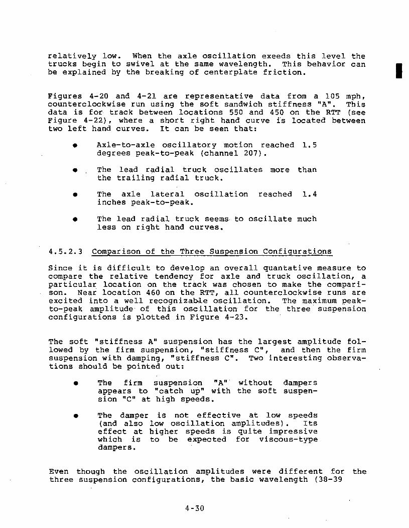
relatively low. When the axle oscillation exeeds this level the trucks begin to swivel at the same wavelength. This behavior can be explained by the breaking of centerplate friction.
Figures 4-20 and 4-21 are representative data from a 105 mph, counterclockwise run using the soft sandwich stiffness "A". This data is for track between locations 550 and 450 on the RTT (see Figure 4-22), where a short right hand curve is located between two left hand curves. It can be seen that:
• Axle-to-axle oscillatory motion reached 1.5 degrees peak-to-peak (channel 207).
• The lead radial truck oscillates more than the trailing radial truck.
• The axle lateral oscillation reached 1.4 inches peak-to-peak.
• The lead radial truck seems to oscillate much less on right hand curves.
4.5.2.3 Comparison of the Three Suspension ConfigurationsSince it is difficult to develop an overall quantative measure to compare the relative tendency for axle and truck oscillation, a particular location on the track was chosen to make the comparison. Near location 460 on the RTT, all counterclockwise runs are excited into a well recognizable oscillation. The maximum peak- to-peak amplitude of this oscillation for the three suspension configurations is plotted in Figure 4-23.
The soft "stiffness A" suspension has the largest amplitude followed by the firm suspension, "stiffness C", and then the firm suspension with damping, "stiffness C". Two interesting observations should be pointed out:
• The firm suspension "A" without dampersappears to "catch up" with the soft suspension "C" at high speeds.
• The damper is not effective at low speeds(and also low oscillation amplitudes). Its effect at higher speeds is quite impressivewhich is to be expected for viscous-typedampers.
Even though the oscillation amplitudes were different for the three suspension configurations, the basic wavelength (38-39
4-30
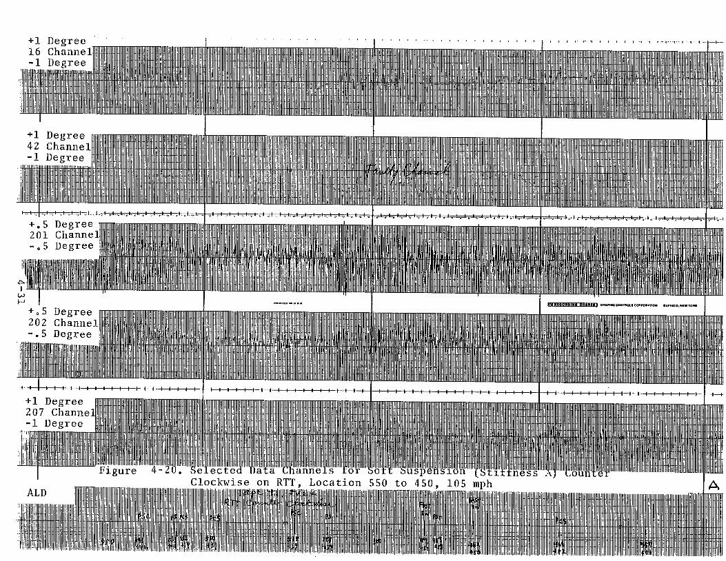
l - l , | vl -vl „l~vl ,1 .1 - l - , - l v l , 1. .
+.5 Degree 201 Channel
-7+TJ---1 t l . , t . v l v l , 1 . \ v J . ^ 1. J t, l<—'—if •**v • »-i
i
+05 Degree 202 Channel -.5 Degree
: COMTRMt COflFOMTKM BUFFUO. NtH TOUR
-f-■*— — 1— I— I— I— I— I— B i l l— |— |— |— |— |— J— |— |— ►■ + +
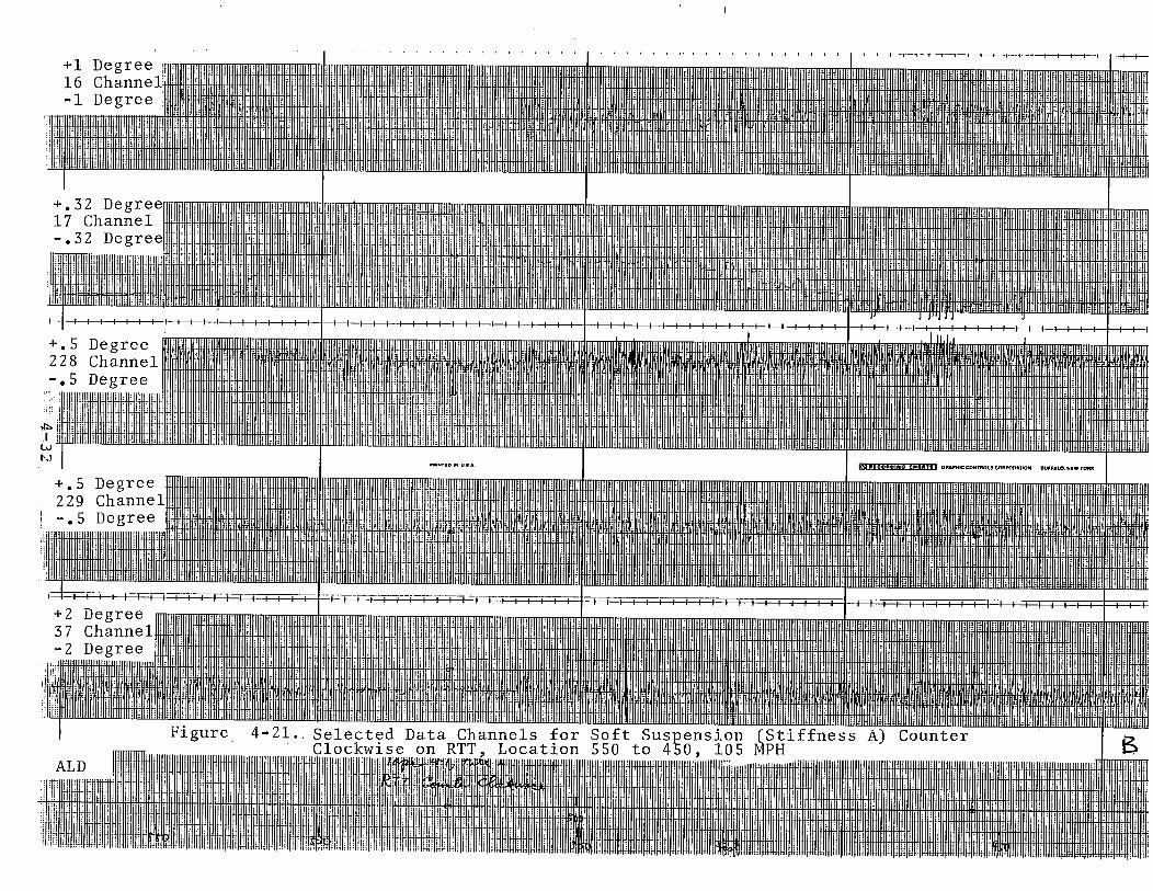
I
+1 Degree 16 Channel;!! -1 Degree
1
Figure 4-22. RTT and Balloon Loop4-33

PEA
K
OS
CIL
LATI
ON
A
MP
LIFI
DE
, D
EGR
EE
P-
1.2
.0
0 . 8
0.6
0.4FIRM"C" PRIMARYSUSPENSION
0.2
//
//
£
/A /
//
/
FIRM C PRIMARY SUSPENSION WITH DAMPER
o ----------------- 1------------------1------------------1----------------- 1----------------- 1------------------ 1______ :____i__________ i_40 50 60 70 80 90 100 110 120
SPEED, MPH
Figure 4-23. Axle-to-Axle Oscillation Amplitude, Lead Radial Truck (Counterclockwise RT.T Runs at. Location 460)
140

feet) is not changed and the signature of the oscillations persisted no matter which configuration was used.
Figures 4-24 and 4-25 compare the soft "A" and the firm "C" suspensions passing through the same area (location 550 to location 450 on the RTT) at the same speed (95 mph) .
Figure 4-26 gives the same data channels for a firm suspension with dampers going through the same test area at a higher speed (116 mph). The dampers are effective in controlling the oscillation such that at 116 mph the amplitudes are smaller than those associated with either of the other two suspension configurations .
4.5.3 STEERING BIAS IN THE LEAD TRUCKThe non-symmetric behavior at the lead radial truck was pointed out earlier. When making counterclockwise runs on the RTT, the levels of axle and truck oscillation are smaller on right hand turns than on left hand turns.
When firm "C" suspension was used (without dampers) , test runs were made both clockwise and counterclockwise on the RTT. Figures 4-27 and 4-28 provide the comparison of a counterclockwise run and a clockwise run through the same area where there is a reverse curve (location 550 to 450). Even though the two runs were made at different speeds (118 mph and 109 mph), the reversal in the non-symmetric curving behavior is quite apparent. The quieter right hand curve during the counterclockwise run has become the more violent curve when it became a left hand curve during the clockwise run. This pair of runs show that the bias is not due to track input, rather, it is caused by lack of symmetry in the truck. This could be due to geometry or elasticity or both.
Because both the left and right hand curves have rather shallow curvature (0°50')r the bias is brought out more sharply. It is expected that a much less significant difference will be found between left and right hand curves of higher curvature. Data from the Balloon loop and FAST (3° to 7.5° curves), indicated the non-symmetry was much less pronounced.
4.5.4 EFFECTS ON TREAD WEARAxle oscillations were observed on tests of all three suspension configurations ("A", "C" and "C" with dampers). The amplitudesmay have been acceptable from safety and ride qualty points of view, but these oscillations do induce wear.
4-35

I
I I I I I
!
+ 142
jj
DegreeChannelDegree
+.5 Degree 202 Channel
ALDFigure 4-24,
liBi
Selected Data Channels Counter Clockwise on R

+1 Degree 16 Channel -1 Degree

’igure 4-26,ALDM I
Selected Data ChannelsforFirm(Stxffness^Dampers Counterclockwise on RTT, Location 550 to 450, 116 mph

+1 Degree 16 Channel] -1 Degree
I I i l > I
+1 Degree 42 Channel -1 Degree tr
-I—I—I—I—1—|—I—H H — I— I— I— I— i— 1— I— I— i— i— I— !— I--1— i— l— t— H H — I— I— I— — I— I— I— I— I— I— I— I— I— I— I— I— I- H— I— I— I— I— I— I— |— I— I— I— I— I— |— |— |— |— |— H H— I— I— I— I— I— I— I— I— I— I— I— I— I -
+.5 Degree 201 Channel -•5 Degree
LOKO
1 ; n -
+.5 Degree 202 Channel -.5 Degree
'No. BSH 11*2963-21
i-1
!!!
ALDFigure 4-27. Selected Data Channels for Firm (Stiffness "C") Suspension
Counterclockwise on RTT, Location 550 to 450, 118 mphW L ff l 3 0 ,

+142- 1
DegreeChannelDegree
—I—I—I—. i i
i +.5 ! 201 ! -.5
, Liiiiniu o + .5
202
l l l I - i i i 1— I I I = I I | _=F T+ 1 207 - 1
ALDFigure 4-28. Selected Data Channels for Firm (Stiffness "C") Suspension
Clockwise on RTT, Location 450 to 550, 108 mph H

Axle yaw, which was the primary oscillatory mode observed, reached peak-to-peak amplitudes of greater than 1° above 110 mph for the firm "C" suspension without damping (the configuration used in it ia lly in l i f e testin g). At this yaw rate, assuming that each of the two axles is producing half of the amplitude, the equivalent longitudinal displacement is approxmately 0.25 inch peak-to-peak at each wheel-rail contact point. since a complete cycle of oscillation is accomplished in 38 feet, the total longitudinal s lip would be approximately 0.5 inch over a 38-foot distance of travel. Such slip would be producing oscillatory longitudinal adhesive forces which would not be normally present.
Combined with the longitudinal slippage, the lateral position oscillation was typically measured at 1 inch peak-to-peak somewhat independent of suspension configurations or speed. Even through the position change (measured relative to the rail by a single AOA position transducer) may be partia lly due to rolling with changing axle heading, there w ill be a contribution due to lateral creep. The creep force w ill be added vectorially to the longitudinal shear load on the contact patch.
The presence of significant longitudinal slippage caused by osc illa to ry axle yaw may be the cause of the unusual wear pattern of a narrow, polished line near the center of the tread observed during the in itia l l i f e te sts .
4 . 5 . 5 CONCLUSIONS ■ - O N ^ P ^ M T Y - " y y y
• There appearsfelto.; be an -ih^^eht -tendency^ for^ -the two a x le s^ :i^ toy-p^i-flata = rin o u t - o f ; at IM^i^meSr iclwMy^^inglh of approximately 38j.5 :-fea^^-Th i s^wa^eiength was not e ff ec@dr byf thieEfii|:i "e: off^uspf#ialbn ; elements J L'
• S tiffer ': uspjensl')9n';“'eli^iffen^s' pedaeedthe amplitude j i ’ :Qfj Ioscli-iati|on, - bi t:-,: ytheincreased y o s c i H a t i w i t h -speed indicates; jthat^'; the? %.ude ~Iwi 11 bereached tCaih'Jgjiieii: | s p e e d - - ;• - - -
• Dampers appear tb ;be very effective yin lim iting (not eliminating) th e -o s c illa tio n at higher speeds.
e As axle yaw oscillation attains higher amplitudes, the truck swivels with the axles.
• A slight non-symmetry was observed in the lead radial truck. The axles on the truck tend to o scilla te on le ft hand 0°50' curves
4-41
rather smoothly. This bias was no longer noticeable on curves of higher curvature (FAST track and Balloon Loop).
• Sustained, axle yaw oscillations and longitudinal slippage may be the cause of rapid wheel tread wear lowering of the critical speed experienced during life testing.
4.6 RIDE QUALITY TEST RESULTS
At the end of the performance te st , a special ride quality test was conducted. The ride quality test was scheduled to be repeated at the completion of the 40,000 miles of l i f e tests and again at the end of the 80,000 mile l i fe test series. The plan was to compare the acceleration data and the axle and truck swivel data to determine whether the truck performance had deteriorated as a result of the running te sts . Since the truck performance did not meet earlier expectations, the truck was not expected to be operated for the fu ll l i f e te st . Therefore, a fin al ride quality test was to be conducted when the truck completed 40,000 miles of operation or when the operation speed deteriorated to the point that no more benefit could be derived from further testing. Data from this second ride quality measurement was to be compared to the results from the earlier tests . The l i fe test was terminated prior to the completion of the required mileage so the second ride quality test was not performed*,
r
4-42

Radial Axle Truck Test Results Report, 1982 US DOT, FRA, ENSCO, Inc, M Liles, R Scofield