rfid model for simulating framed slotted aloha based anti ... · framed slotted aloha algorithms...
TRANSCRIPT
14
RFID Model for Simulating Framed Slotted ALOHA Based Anti-Collision Protocol
for Muti-Tag Identification
Zornitza Prodanoff1 and Seungnam Kang2 1University of North Florida
2National Seoul University 1USA
2South Korea
1. Introduction
Radio Frequency Identification (RFID) networks use radio signal broadcast to automatically
identify items with attached RFID tags. A tag consists of a microchip that stores a unique
identifier and an antenna. The tag’s antenna is attached to the chip and can transmit a
unique tag identifier to a reader (also called interrogator). The reader is capable of learning
the set of tags within its interrogation range. The process of learning in-range tags is called a
census. After an initial census is completed, the reader can answer queries about the
presence of specific tag(s) within its range sent to it from other type of devices.
RFID systems have abundant benefits as compared to the barcode and smart card systems.
RFID networks use radio frequency as a method of data transmission. Thus, unlike barcode
labels, a tag does not need to be placed in a line of sight position from the reader, or even get
in contact with a reader as smart cards, in order to be identified successfully. Depending on
whether they use low, high, or ultrahigh transmission frequencies, RFID tags are identifiable
within 3 meters span in case of a typical far-field reader [Want06] or at even further
distances. Therefore, RFID tags are used more flexibly and conveniently than existing
barcode and smart card implementations.
Moreover, some commercial implementations of RFID tags can store data in the amount of
16bytes - 64Kbytes [Finkenzeller03]. RFID tags can hold the same amount of data compared
to smart cards, and much larger volume than barcodes. In addition, RFID tags are getting
less expensive. The cost of RFID chips at the time of this study is less than 10 cents, while
back in 1999, for example, was around 2 US dollars. Since tag readers have limits on their
operations range imposed by the frequency of the wireless signal used, when RFID
networks need to cover large spaces, multiple readers need to be used. The cost of current
reader implementations is hundreds of US dollars. As a result, RFID networks may not be
yet suitable to track large inventories of inexpensive items, but they are certainly becoming
more affordable and can be used to track different types of items, e.g. live stock, pets, and
valuable goods. Due to these advantages RFID systems are emerging as one of the
alternative technologies of our time.
www.intechopen.com

Current Trends and Challenges in RFID 280
One of the world biggest supply chains Wal-Mart has required suppliers to implement RFID networks in at least 12 of its 137 distribution centres by the end of 2006. The Proctor & Gamble Co. is the first of about 100 suppliers to conform to Wal-Mart’s requirements to tag its products with RFID chips [Computerworld07]. The US Navy finished its pilot of a passive RFID system to support the loading of supplies into cargo containers in May 2004. According to the related final report the RFID process increased the speed and efficiency of the cargo checking process, while less people were needed to support the new RFID based system as compared to the legacy implementation [Weinstein05].
1.1 Physical composition
An RFID system is made up of an application, a reader and tags.
The application is a program installed on a (proxy) computer which can control readers.
The reader is a device which runs functions such as reading, writing and authentication. When the reader gathers data from tags it transmits to the computer application.
The tag is used to identify an object and is located on (or in) the object itself. A reader is connected to the computer and has a transmitter and receiver, while a tag has a control unit (chip) and a coupling element (antenna).
Fig. 1. RFID Physical Composition [Finkenzeller03]
RFID tags can be passive, i.e. not having an internal energy source or active, internal battery powered. A reader typically charges a set of passive tags within its interrogation zone using inductive coupling; the reader broadcasts electromagnetic signal then the tag’s antenna absorbs and stores the signal’s energy into an on-board capacitor. This technique is called load modulation for near-field coupling and back scattering for far-field coupling. After charging its battery it can be activated.
www.intechopen.com

RFID Model for Simulating Framed Slotted ALOHA Based Anti-Collision Protocol for Muti-Tag Identification 281
1.2 Framed slotted ALOHA anti-collision algorithm
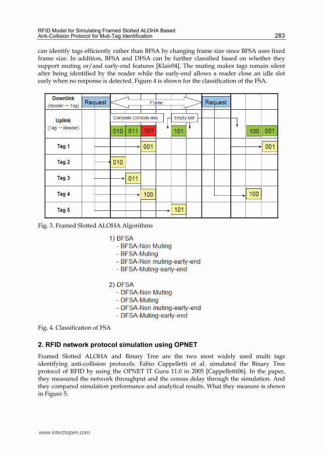
The ALOHA algorithm is a collision resolution algorithm based on Time Division Multiple Access (TDMA). There are three flavors of the original ALOHA algorithm: (Pure) ALOHA, Slotted ALOHA and Frame Slotted ALOHA [Zürich04]. In Figure 2, X and Y axis represents the read cycle and tags respectively. The read cycle is the time interval between neighboring two REQUEST commands and it can be repeated until all tags in the interrogation range are identified. Note that there no slots are used in the (Pure) ALOHA algorithm (Figure 2: (a)) while the read cycle is divided into several continuous slots in the Slotted ALOHA (Figure 2: (b)) and Framed Slotted ALOHA algorithm. Furthermore, a frame is comprised of the number of slots in the Framed Slotted ALOHA algorithm (Figure 3: A slot is a discrete time intervals synchronized by the reader, sufficiently long in duration to allow a tag to transmit its ID and the ID’s 16-bit CRC code. A set of slots are grouped into frames. When size is fixed, each consecutively transmitted frame has the same number of slots.
(a) (Pure) ALOHA
(b) Slotted ALOHA
Fig. 2. Pure and Slotted ALOHA Algorithms
www.intechopen.com

Current Trends and Challenges in RFID 282
The reader broadcasts the REQUEST command to the tags located in the reader’s interrogation range during the downlink while the tags transmit their data to the reader during the uplink. As all activated tags share the uplink partial or complete collision can occur in the (Pure) ALOHA algorithm. However, if the data is transmitted using the slot of frame the partial collision can be eliminated. Furthermore, to reduce the fraction of collision occurrence tags send their data no more than once within a frame, which is the Frame Slotted ALOHA algorithm. We next present in more detail the operation of the three ALOHA algorithms introduced above.
1.2.1 (Pure) ALOHA
A tag itself decides the data transmission time randomly as soon as it is activated. The transmission time is not synchronized with both the reader and the other tags at all. When the electricity is charged by the reader’s electromagnetic wave tags transmit data after receiving the REQUEST command from the reader. If multiple tags transmit data imminently (whether earlier or later) then a complete or partial collision occurs (Fig. 2 (a)). Retransmitting after random delay is the solution for a collision. During the read cycle the reader receives the data and identifies tags sent data without collision. When a read cycle is done then the reader broadcasts the SELECT command with the tag’s unique identifier received from the tag. Once tags are selected the tags stop responding for the request command i.e. the selected tags keep silence until whether they receive other commands e.g. authenticate, read and write or the tag’s power is off by being located out of the reader’s power range. When the tag is reentered into the reader’s interrogation range it restart transmitting its data to the reader. The advantage of this algorithm is simplicity.
1.2.2 Slotted ALOHA
It is obtained by the addition of a constraint to the (Pure) ALOHA. The read cycle is divided into discrete time intervals called slot and which is synchronized with the entire tags by the reader. Thus, tags must choose one of the slots randomly and transmit data within a single slot. Transmission begins right after a slot delimiter (Fig. 2 (b)). This causes that packets either collide completely or don’t collide at all i.e. there is no partial collision in the Slotted ALOHA algorithm. This reduces wasting the read cycle relatively as compared with the (Pure) ALOHA algorithm. However, the empty slot can be occurred in the read cycle and the disadvantage is that it requires a synchronization mechanism in order for the slot-begin to occur simultaneously at all tags.
1.2.3 Framed slotted ALOHA
Framed Slotted ALOHA algorithm uses the frame which is the discrete time interval of the read cycle and each frame is divided into the same number of slots. There are multiple frames in a single read cycle and the frame size is decided by the reader (Figure 3: There is a constraint that the tags can transmit data only once in each frame. It may reduce the number of collided slots and it shows the best performance among them.
1.3 Classification of the framed slotted ALOHA protocol
FSA (Framed Slotted Aloha) can be classified into the BFSA (Basic Framed Slotted Aloha) and the DFSA (Dynamic Framed Slotted Aloha) according to whether which uses fixed frame size or variable frame size [Klair04]. If the number of actual tags is unknown DFSA
www.intechopen.com
RFID Model for Simulating Framed Slotted ALOHA Based Anti-Collision Protocol for Muti-Tag Identification 283
can identify tags efficiently rather than BFSA by changing frame size since BFSA uses fixed frame size. In addition, BFSA and DFSA can be further classified based on whether they support muting or/and early-end features [Klair04]. The muting makes tags remain silent after being identified by the reader while the early-end allows a reader close an idle slot early when no response is detected. Figure 4 is shown for the classification of the FSA.
Fig. 3. Framed Slotted ALOHA Algorithms
Fig. 4. Classification of FSA
2. RFID network protocol simulation using OPNET
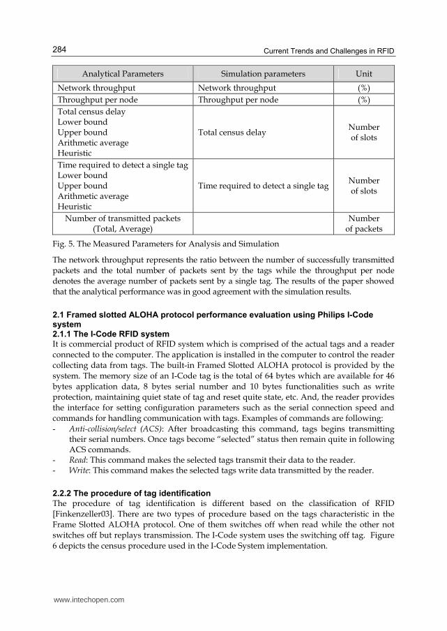
Framed Slotted ALOHA and Binary Tree are the two most widely used multi tags identifying anti-collision protocols. Fabio Cappelletti et al. simulated the Binary Tree protocol of RFID by using the OPNET IT Guru 11.0 in 2005 [Cappelletti06]. In the paper, they measured the network throughput and the census delay through the simulation. And they compared simulation performance and analytical results. What they measure is shown in Figure 5.
www.intechopen.com
Current Trends and Challenges in RFID 284
Analytical Parameters Simulation parameters Unit
Network throughput Network throughput (%)
Throughput per node Throughput per node (%)
Total census delay Lower bound Upper bound Arithmetic average Heuristic
Total census delay Number of slots
Time required to detect a single tag Lower bound Upper bound Arithmetic average Heuristic
Time required to detect a single tag Number of slots
Number of transmitted packets (Total, Average)
Number
of packets
Fig. 5. The Measured Parameters for Analysis and Simulation
The network throughput represents the ratio between the number of successfully transmitted
packets and the total number of packets sent by the tags while the throughput per node
denotes the average number of packets sent by a single tag. The results of the paper showed
that the analytical performance was in good agreement with the simulation results.
2.1 Framed slotted ALOHA protocol performance evaluation using Philips I-Code system 2.1.1 The I-Code RFID system
It is commercial product of RFID system which is comprised of the actual tags and a reader
connected to the computer. The application is installed in the computer to control the reader
collecting data from tags. The built-in Framed Slotted ALOHA protocol is provided by the
system. The memory size of an I-Code tag is the total of 64 bytes which are available for 46
bytes application data, 8 bytes serial number and 10 bytes functionalities such as write
protection, maintaining quiet state of tag and reset quite state, etc. And, the reader provides
the interface for setting configuration parameters such as the serial connection speed and
commands for handling communication with tags. Examples of commands are following:
- Anti-collision/select (ACS): After broadcasting this command, tags begins transmitting their serial numbers. Once tags become “selected” status then remain quite in following ACS commands.
- Read: This command makes the selected tags transmit their data to the reader. - Write: This command makes the selected tags write data transmitted by the reader.
2.2.2 The procedure of tag identification
The procedure of tag identification is different based on the classification of RFID
[Finkenzeller03]. There are two types of procedure based on the tags characteristic in the
Frame Slotted ALOHA protocol. One of them switches off when read while the other not
switches off but replays transmission. The I-Code system uses the switching off tag. Figure
6 depicts the census procedure used in the I-Code System implementation.
www.intechopen.com

RFID Model for Simulating Framed Slotted ALOHA Based Anti-Collision Protocol for Muti-Tag Identification 285
Fig. 6. Tag Identification Procedure of the I-Code System
The reader broadcasts the ACS command with a random value, frame size to make tags
transmit their serial number to the reader. When the tag receives a command from the
reader first of all it identifies the type of command, and if it is ACS and the status of tag is
not ‘selected’ then it computes the response slot number using the random value and frame
size (0 ≤ response slot < frame size) as parameters. Random value is used to prevent the
same collisions from occurring repeatedly. The serial number in the computed slot is
transmitted to the reader by the tag. During an uplink, data transmission from tags to
reader, the reader can identify tags transmitted without collision. The results of a read cycle
(the number of empty slots, the number of slots filled with one tag and the number of
collided slots) are used for analysis. Once the tag is identified the tag remains quiet until
other command e.g. read or write is broadcasted with serial number. And if the tag re-enters
the reader’s power zone after moving out, that needs re-identification. The read cycle is
repeated till reaching the assurance level, the probability of identifying all tags in the
reader’s range.
2.2.3 Basic framed slotted ALOHA
Through simulation we can measure the total census delay by varying the frame size for
given number of tags. Then we can find the optimal frame size which results in the
minimum total census delay, for given number of tags (see Figure 7).
The optimal frame size, resulting in minimum census delay, can be determined according to
the total number of tags. Figure 8 presents an example of the relationship between total
number of tags and frame size. For example, the optimal frame size for 80 active tags is 45,
while for 30 passive tags it is 40.
2.2.4 Dynamic slot allocation for dynamic framed slotted ALOHA
To maximize network throughput frame size (the number of allocated slots in the read cycle)
should be chosen in accordance with the number of tags since for the same fixed slot size,
number of total collisions during a census increases with increase in total number of tags.
www.intechopen.com

Current Trends and Challenges in RFID 286
Fig. 7. Example of Total Census Delay (Tag Collection Time) Using Static Frame Size [Bin05]
Due to the nature of the Framed Slotted ALOHA protocol, the read cycle time is divided by the number of slots in a frame and packet data (tag ID number plus CRC) to be transmitted should occupy a single slot. If there are lots of tags and frame size is small then the probability of collisions will be increased and the number of identified tags is decreased, because tags will be competing for a lesser number of slots within a frame. On the contrary, if the reader reads few tags with too big frame size then the probability of collision is decreased , but at the expense of the response time being increased. There is optimal frame size that makes minimum number of read cycles for certain number of tags. The dynamic slot allocation is choosing the optimal frame size (in number of fixed slots) during the tag read cycle. However, the problem is that the number of tags is unknown. So, the reader should estimate the number of tags in each read cycle with the result of the previous read cycle (number of empty slots, number of slots filled with one tag, number of collided slots) and current frame size.
2.3 Developed approaches of the framed slotted ALOHA protocol
The key difference of the developed Framed Slotted ALOHA protocol is how they estimate the number of tags and what they estimate.
2.3.1 H. Vogt’s algorithm
In this scheme, they estimate the number of tags using the current frame size and the result of read cycle. And then updates the current frame size using the estimated number of tags and previous frame size. The procedure of this algorithm is shown in Figure 9. Variable ‘N’, ‘N0’, ‘n_est’ and ‘stepN’ represent the frame size, temporary frame size, the
www.intechopen.com

RFID Model for Simulating Framed Slotted ALOHA Based Anti-Collision Protocol for Muti-Tag Identification 287
estimated number of tags and the counter for the cycle performed with currently estimated framed size, respectively. Variable ‘c’, ‘t’ represents the result of a read cycle comprised of three integers; number of empty slots, number of slots filled with one tag and number of collided slots, and variable ‘t’ represents the temporary number of estimated number of tags. In order to estimate the number of tags two estimation functions are used; lower bound and Chebyshev’s inequality. Lower bound simply estimates the number of tags is bigger than the summation of the number of slots filled with one tag and two-times of the number of collided slots:
Number of tags Number of filled slots with one tag 2 Number of collided slots (1)
When the lower bound is used the real value of number of tags is underestimated.
Fig. 8. Example of Optimal Frame Size For Minimum Census Delay [Bin05]
Chebyshev’s inequality measures the difference the real values and expected values to
estimate the number of tags for which the difference becomes minimal [Vogt02]. The
number of tags are estimated using the currently used frame size (N) and the results of
previous read cycle <c0, c1, ck> representing the number of empty slots, the number of slots
filled with one tag and the number of collided slots respectively. And , , ,
0 1 2, ,N n N n N na a a
denotes the expected number of empty slots, the expected number of slots filled with one
tag and the expected number of collided slots respectively where N and n represent the
frame size and the number of tag respectively. Lower bound is more accurate for low values
of n while Chebyshev’s inequality is steadier for a wider range of n [Vogt02].
www.intechopen.com

Current Trends and Challenges in RFID 288
,
0 0
,
0 1 1 1
,
2
, , , min
N n
N n
vd k
N n
k
a c
N c c c a c
ca
(2)
* Function: VogtAlgorithm () - Variable: integer : N, N0, n_est, stepN, c, t - N = minimum frame size - repeat begin while stepN is smaller than maxStep:
stepN++; Perform a read cycle with N and store the result in c Estimate number of tags with N and c, and then store result in t If t is bigger than n_est then save t in n_est.
Call adaptFrameSize(N, n_est) and save value in N0. If N0 is bigger than N then reset stepN with 0. And, save N0 in N.
- repeat end * Function: adaptFrameSize(N, n_est) - Return type : integer - repeat begin while n_est is smaller than low value for choice of N:
Store N/2 in N. - repeat end - repeat begin while n_est is bigger than high value for choice of N:
Store 2*N in N. - repeat end
Fig. 9. Pseudo Code of H. Vogt’s Algorithm
Figure 10 presents the optimal frame size resulting from the execution of function adaptiveFrameSize (N, n_est) using as an input the estimated number of tags and the value of the current frame size N. The optimal frame size is selected for a range of tags, based on a low and high margin.
Fig. 10. Choosing Optimal Frame Size [Vogt02]
2.3.2 Bin ZHEN et al.’s algorithm
This algorithm estimates the number of tags using the posteriori probability. The posteriori probability of k tags for an observed slot is as below:
www.intechopen.com

RFID Model for Simulating Framed Slotted ALOHA Based Anti-Collision Protocol for Muti-Tag Identification 289
0
0 1
0
( )( )
1 ( ) ( )
if 0, 1if 2
kk
p ip i
p i p i
kk
(3)
The a posteriori expected value of the number of tags is respectively, 0 for an empty slot, 1 for
a slot filled with one tag, and 0
2( )
N
kkkp i tags for a collided slot. Thus, the estimated tag sets
from the current read cycle is1( )p i 0
2( )
N
kkkp i . Then, the estimated number of tags comes
from the result of the ith read cycle is,
( 1)est
n i s Kg (4)
Where K = 2.39 is a constant for collided slots [Bin05]. And, the frame size (N) in the (i+1)th read cycle is
i 1 * ( 1)
1 – 1.4 Passive tag
0.8 – 1 Active tag
estN H n i
H
H
(5)
where H is a constant, which maps the tags to the frame size. The update of the frame size
occurs when ( 1)est
n i ≥ γ * ( )est
n i . Here, γ is constant value which is 1.15 and it denotes a
threshold to handle random jitter of number of estimated tags. The procedure of this
algorithm is shown in Figure 11.
* Function: BinZHENAlgorithm () -Variable: integer : N, i, c, s, nest(i) N = minimum frame size i = 0 - repeat begin while i is smaller than the number of read cycle for confidence level:
i ++; Perform a read cycle with N and store the result in c for collided slots, s for success slots. Estimate number of tags with N, c and s, and then store result in nest(i). If nest(i) is bigger than γ * nest(i - 1) then Call calculateFrameSize(nest(i), tagType) and save value in N.
i = 0. - repeat end * Function: calculateFrameSize(nest(i), tagType) - Return type : integer - If tagType is passive then N(i) = (random value of 1 – 1.4) * nest(i) else N(i) = (random value of 0.8 – 1) * nest(i) - return N(i)
Fig. 11. Pseudo Code of Bin ZHEN et al.’s Algorithm
www.intechopen.com

Current Trends and Challenges in RFID 290
2.3.3 EDFSA (Enhanced Dynamic Framed Slotted ALOHA)
This algorithm estimates the number of unread tags instead of number of tags to determine
the frame size. H. Vogt’s algorithm shows poor performance when the number of tags
becomes large because the variance of the tag number estimation is increased according to
the number of tags increase [Rom90]. Therefore, to handle the poor performance of large
number of tag identification EDFSA algorithm restricts the number of responding tags as
much as the frame size. Conversely, if the number of tags is too small as compared with the
frame size it reduces the frame size. To estimate the number of unread tags equation (2) is
used. The procedure of EDFSA algorithm’s read cycle is shown in Figure 12.
Fig. 12. Read Cycle of EDFSA Algorithm
3.1 Evaluating delays
To evaluate the implementation of the BFSA protocol I first evaluated the total census delay of the tag reading process. It is comprised of three different delays; success delay, collision delay and idle delay. Thus, the total census delay is defined as
[ ] [ ] [ ]T n n C n I n (6)
where n is success delay, C[n] is collision delay and I[n] is idle delay [Cappelletti06]. The unit of delay can be defined as a slot duration T (sec) and it is defined as,
ID (bits)
data_rate (bps)T (7)
where ID (bits) is the size of the packet containing tag’s ID, and data_rate (bps) is the data rate from tag to reader.
www.intechopen.com

RFID Model for Simulating Framed Slotted ALOHA Based Anti-Collision Protocol for Muti-Tag Identification 291
3.1.1 BFSA-non-muting
It is necessary that evaluating of the read cycles satisfying the confidence level α since it is
used to determine total census delay. The assurance level α is the probability of identifying
all tags in the reader’s interrogation range [Vogt02] e.g. if α = 0.99 which means one or more
missing tags, less than 1% of all, are allowed. The probability of r tags responding in a slot in
the ith read cycle is given by [Bin05]
1 11
r n r
r
np i
r N N
(8)
where N is the given frame size (slots) and n is the number of tags to be read in the ith read
cycle. From the equation 8, the probability of having one or more idle (po(i)), successful
(p1(i)), and collide (pk(i)) slots in the ith read cycle are defined as:
0
1( ) 1
n
p iN
(9)
1
1
1( ) 1
nn
p iN N
(10)
1 0
( ) 1 ( ) ( )k
p i p i p i (11)
Then the expected number of the successful transmissions in the ith read cycle becomes
Np1(i) since a read cycle has N slots [Bin05]. The probability of having an unread tag after R
read cycle is given by [Bin05] [Klair04]
1
1
( )( ) 1 1
R
missi
Np ip i
n
(12)
R represents the number of required read cycles to identify a set of tags with a confidence level α. As the number of tags n and the frame size N are the same for all read cycle, p1(i) is constant. That makes equation 13 as,
1( ) 1 1
R
miss
Npp i
n (13)
If we solve the equation 13 for R we can obtain the condition of R as below: [Klair04]
1 1
1
log(1 ) log(1 ) log(1 )
1 1log 1 1 log 1
log 1
n nR
Np Nn
n N N
n
(14)
www.intechopen.com

Current Trends and Challenges in RFID 292
The ceil function is used since R is the integral value. By using R and if the number of tags is known, we can evaluate the theoretical delay of successful (n), idle (I[n]), and collision (C[n]) transmission as follows [Klair04]:
1
n Np RT (15)
0
( )I n Np RT (16)
0 1
( ) (1 )C n NRT p p (17)
where N is a frame size, T is slot duration. The summation of those three delays represents the total census delay.
3.1.2 BFSA muting
Muting decreases the number of tag’s responses after every read cycle. Hence, the number
of responding tags in the ( 1)i th read cycle is less than or equal to those in the ith read
cycle. The number of responding tags in the ( 1)i th read cycle is evaluated as [Bin05],
1
( 1) ( ) ( )n i n i p i N (18)
where 1( ) ( )p i N i represents the number of tags muted in the ith read cycle. And we can
calculate the R with the given n and N by using the equation 14. Then the collection rounds
to read all tags R is given by solving the following equation [Bin05]
1
1
( )( ) 1 1
( )
R
missi
Np ip i
n i
(19)
By using Rmin, if the number of tags is known, we can evaluate the theoretical minimum delay of successful (n), idle (I[n]), and collision (C[n]) transmission by using the equation 15, 16, and 17. And, their summation yields the minimum total census delay.
3.2 Evaluating network throughput
Network throughput can be defined as the ratio between the number of successfully transmitted packets (one per tag) and the total number of packets sent by the tags during the census [Cappelletti06]. Suppose that there are n tags to be read. Then, the total number of packets sent by n tags during a census for non-muting BFSA is
[ ]P n nR (20)
where R is the number of required read cycles needed to identify a set of tags with a confidence level α. Since tags can transmit only once in a read cycle. Now we can calculate the network throughput as
[ ][ ]
nS n
P n R
(21)
where α is assurance level, n is total number of identified tags, and P[n] is the total number of packets sent by the tags during the census.
www.intechopen.com

RFID Model for Simulating Framed Slotted ALOHA Based Anti-Collision Protocol for Muti-Tag Identification 293
4.1 Validation of the models
In this project, I implemented two Aloha models; BFSA-Muting and BFSA-Non-Muting. To validate the model I analyzed the log file [appendix A, B] of the models and compared with the pseudo code. For easy comparison I put the figures describing the events of the simulation comes from the log file.
4.1.1 Simulation information
For the simplicity I put a reader and eight tags, and the same given conditions are used between two simulations. The reader and tags being used in the simulation are shown in Figure 13 (a) while the given conditions are shown in Figure 13 (b).
(a) A Reader and Tags (b) Given Simulation Conditions
Fig. 13. Simulation Information
The time required for the packet transmission can be calculated by using the given packet size and the data rate among reader and tags. They are shown in Figure 14.
Fig. 14. Packet Transmission Time
I assume that the propagation delay is negligible since in case of a typical far-field reader has 3 meters span interrogation range [Want06]. Consider the speed of light is 299,792,458 m/s then the delay of 3 meters will be 1-8 seconds. And I also assume the calculation delay of the reader and of the tag is negligible as simplicity is the strong point i.e. it does not need complex calculation both for the reader and for the tag.
4.1.2 BFSA-muting
For the validation of the simulation model we compared the analytical results (obtained based on an algorithm presented in [Klair04] (see Figure 15)) with our simulation results.
www.intechopen.com

Current Trends and Challenges in RFID 294
When the reader starts a census procedure the number of unread tags is initialized to the number of actual tags in range. While the census is performed to identify unread tags the number of identified tags, collided slots, idle slots, and the current frame size are stored as a running total. If there is no collision from tags the total delay, collision delay, and idle delay are calculated. T represents the duration of a single slot. The log from the BFSA-Muting simulation is shown in Appendix A. Figure 16 depicts the sequence of events during the BFSA-Muting simulation. Through analyzing the log we can check the correctness of the implementation.
1 BEGIN; 2 Initialize unread tags = actual number of tags; 3 while True do 4 Perform a read cycle for unread tags; 5 Store the number identified tags; 6 Store the number slots filled with collisions; 7 Store the number of slots filled with idle responses; 8 Store current frame size; 9 if (No Collisions) then 10 Break; 11 else
12 Unread Tags = actual – identified tags; 13 end
14 end
15 Total delay = T × stored frames;
16 Collision Delay = T × stored collision slots;
17 Idle Delay = T × stored idle slots;
18 END;
Fig. 15. Pseudo Code of the BFSA Muting
(a) First Read Cycle of the Simulation
www.intechopen.com

RFID Model for Simulating Framed Slotted ALOHA Based Anti-Collision Protocol for Muti-Tag Identification 295
(b) Second Read Cycle of the Simulation
(c) Third Read Cycle of the Simulation
(d) Fourth Read Cycle of the Simulation
www.intechopen.com
Current Trends and Challenges in RFID 296
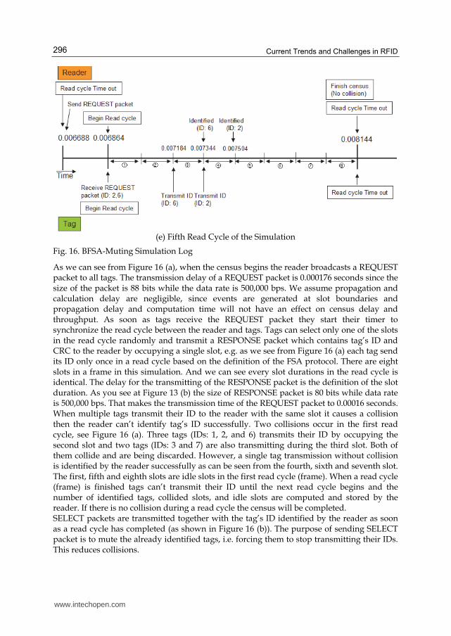
(e) Fifth Read Cycle of the Simulation
Fig. 16. BFSA-Muting Simulation Log
As we can see from Figure 16 (a), when the census begins the reader broadcasts a REQUEST packet to all tags. The transmission delay of a REQUEST packet is 0.000176 seconds since the size of the packet is 88 bits while the data rate is 500,000 bps. We assume propagation and calculation delay are negligible, since events are generated at slot boundaries and propagation delay and computation time will not have an effect on census delay and throughput. As soon as tags receive the REQUEST packet they start their timer to synchronize the read cycle between the reader and tags. Tags can select only one of the slots in the read cycle randomly and transmit a RESPONSE packet which contains tag’s ID and CRC to the reader by occupying a single slot, e.g. as we see from Figure 16 (a) each tag send its ID only once in a read cycle based on the definition of the FSA protocol. There are eight slots in a frame in this simulation. And we can see every slot durations in the read cycle is identical. The delay for the transmitting of the RESPONSE packet is the definition of the slot duration. As you see at Figure 13 (b) the size of RESPONSE packet is 80 bits while data rate is 500,000 bps. That makes the transmission time of the REQUEST packet to 0.00016 seconds. When multiple tags transmit their ID to the reader with the same slot it causes a collision then the reader can’t identify tag’s ID successfully. Two collisions occur in the first read cycle, see Figure 16 (a). Three tags (IDs: 1, 2, and 6) transmits their ID by occupying the second slot and two tags (IDs: 3 and 7) are also transmitting during the third slot. Both of them collide and are being discarded. However, a single tag transmission without collision is identified by the reader successfully as can be seen from the fourth, sixth and seventh slot. The first, fifth and eighth slots are idle slots in the first read cycle (frame). When a read cycle (frame) is finished tags can’t transmit their ID until the next read cycle begins and the number of identified tags, collided slots, and idle slots are computed and stored by the reader. If there is no collision during a read cycle the census will be completed. SELECT packets are transmitted together with the tag’s ID identified by the reader as soon as a read cycle has completed (as shown in Figure 16 (b)). The purpose of sending SELECT packet is to mute the already identified tags, i.e. forcing them to stop transmitting their IDs. This reduces collisions.
www.intechopen.com

RFID Model for Simulating Framed Slotted ALOHA Based Anti-Collision Protocol for Muti-Tag Identification 297
Three SELECT packets are transmitted as shown in Figure 16 (b) with a tag’s ID identified in
the previous read cycle. The size of the SELECT packet is 72 bits and because of the data rate
being 500,000 bps the transmission delay will be 0.000144 seconds. After transmitting
SELECT packets the REQUEST packet is broadcasted to all tags. However, selected tags will
disregard this message. Only unread tags will response to the REQUEST packet.
When the REQUEST packet is delivered to all tags the read cycle is started again. The reader
can synchronize the start time of the read cycle with tags since reader can calculate the
transmission delay of SELECT and REQUEST packet with packets size and data rate. Once
the read cycle is started, the procedure of transmit tag’s ID, of detecting collision, and of
identifying tag’s ID is same with ones in the previous read cycle. When the reader detects no
collision during a read cycle the census will be finished shown in Figure 16 (e).
4.1.3 BFSA-non-muting
There are two major differences from BFSA-Muting; identified tags are not muted and the
assurance level is used for finishing the census. For measuring the assurance level after
finishing every read cycle and finishing the census successfully, the line 9 of Figure 15
would be replaced with Figure 17.
1 measure current assurance level 2 if (Given Assurance level <= Current Assurance level) then
Fig. 17. Computing Assurance Level of BFSA-Non-Muting
In the BFSA-Non-Muting, tags are not muted at all. Thus, the probability of collision
occurrence is higher than the BFSA-Muting and SELECT packet is not necessary to be
transmitted to tags.
(a) First and Second Read Cycle of the Simulation
www.intechopen.com

Current Trends and Challenges in RFID 298
(b) Third and Fourth Read Cycle of the Simulation
(c) Fifth and Sixth Read Cycle of the Simulation
(d) Seventh and Eight Read Cycle of the Simulation
Fig. 18. BFSA-Non-Muting Simulation Log
www.intechopen.com
RFID Model for Simulating Framed Slotted ALOHA Based Anti-Collision Protocol for Muti-Tag Identification 299
In BFSA-Non-Muting when the census begins the reader transmits REQUEST packet to all
tags and they start transmitting their IDs (once in a read cycle). Tags are never muted, so
that all tags continue to transmit for the duration of a census, once every read cycle. Another
difference between BFSA-Non-Muting and BFSA-Muting is that they have different
behavior at the end of each read cycle. As can be seen from Figure 18, the assurance level is
measured at the end of every read cycle and is changed according to the total number of
identified tags given the total number of actual tags. As shown in Figure 18 (a) the identified
tag (ID: 4) sends its ID again during the next frame. Census completes when the assurance
level is satisfied, as shown in Figure 18 (d).
5. Evaluation
In this Section, we evaluate two parameters: total census delay and network throughput. We
compare our simulation results with analytical results, computed by using the equations
from Section 3.
5.1 Total census delay
Total census delay varies depending on the frame size and the number of actual tags in the
BFSA model. If a frame size is either too big or too small as compared to the total number of
tags the delay will be longer because of the increased number of idle slots and collision slots
respectively, i.e. there is an optimal frame size resulting in the least total census delay for
given number of tags. Thus, we first measure the optimal frame size to find the minimal
total census delay for given fixed number of tags to be read (identified). Simulation runs
were conducted by varying the initial number of tags from 10 to 100 with step of 5 while the
given static frame size varies from 10 to 120 with step of 5. 10 census procedures were
simulated for each frame size and given a specific number of tags.
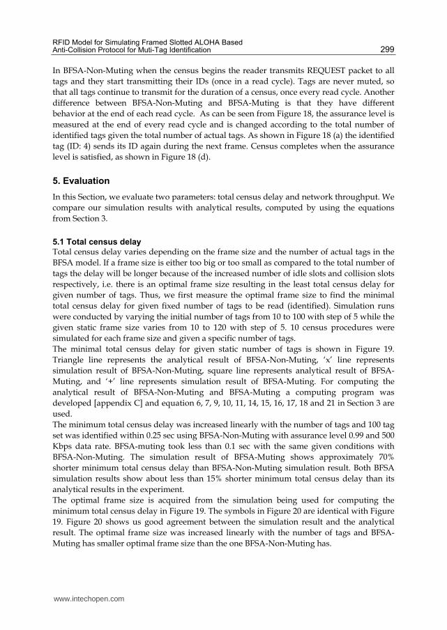
The minimal total census delay for given static number of tags is shown in Figure 19.
Triangle line represents the analytical result of BFSA-Non-Muting, ‘x’ line represents
simulation result of BFSA-Non-Muting, square line represents analytical result of BFSA-
Muting, and ‘+’ line represents simulation result of BFSA-Muting. For computing the
analytical result of BFSA-Non-Muting and BFSA-Muting a computing program was
developed [appendix C] and equation 6, 7, 9, 10, 11, 14, 15, 16, 17, 18 and 21 in Section 3 are
used.
The minimum total census delay was increased linearly with the number of tags and 100 tag
set was identified within 0.25 sec using BFSA-Non-Muting with assurance level 0.99 and 500
Kbps data rate. BFSA-muting took less than 0.1 sec with the same given conditions with
BFSA-Non-Muting. The simulation result of BFSA-Muting shows approximately 70%
shorter minimum total census delay than BFSA-Non-Muting simulation result. Both BFSA
simulation results show about less than 15% shorter minimum total census delay than its
analytical results in the experiment.
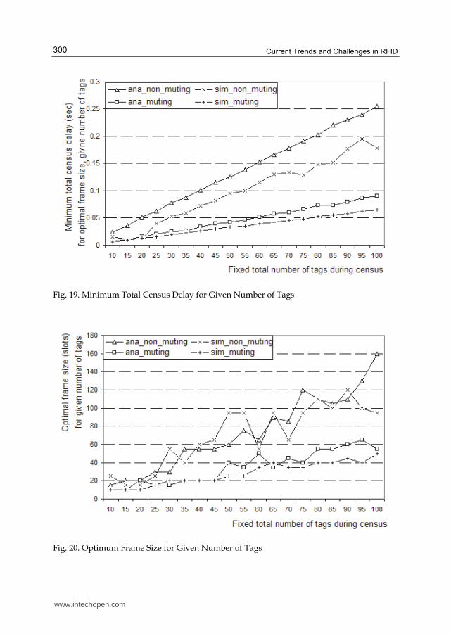
The optimal frame size is acquired from the simulation being used for computing the
minimum total census delay in Figure 19. The symbols in Figure 20 are identical with Figure
19. Figure 20 shows us good agreement between the simulation result and the analytical
result. The optimal frame size was increased linearly with the number of tags and BFSA-
Muting has smaller optimal frame size than the one BFSA-Non-Muting has.
www.intechopen.com
Current Trends and Challenges in RFID 300
Fig. 19. Minimum Total Census Delay for Given Number of Tags
Fig. 20. Optimum Frame Size for Given Number of Tags
www.intechopen.com

RFID Model for Simulating Framed Slotted ALOHA Based Anti-Collision Protocol for Muti-Tag Identification 301
5.2 Network throughput
We evaluate three types of network throughput: maximum throughput, minimum throughput, and mean throughput. Network throughput represents the ratio between successfully transmitted number of packets and total number of transmitted packets during census. All of them show good agreement between analytical result and simulation result and they are shown in Figure 21.
(a) Minimum Network Throughput
www.intechopen.com

Current Trends and Challenges in RFID 302
(b) Maximum Network Throughput
(c) Mean Network Throughput
Fig. 21. Network Throughput
www.intechopen.com

RFID Model for Simulating Framed Slotted ALOHA Based Anti-Collision Protocol for Muti-Tag Identification 303
In Figure 21, network throughput shows good agreement between analytical and simulation result and simulation throughput shows slightly lower than analytical one. Figure 21 tell us that the network throughput of the two BFSA models is getting lower according to the increment of the fixed total number of tags. In Figure 21 (c), we can see mean network throughput of BFSA-muting is 200 - 400% greater than the throughput of BFSA-Non-Muting. Since in the BFSA-Muting the identified tags keep silent thus the total number of transmitted packet would be reduced while in the BFSA-Non-Muting the identified tags never stop transmitting its ID. Thus the difference between two RFID models makes network throughput different.
6. Conclusion
To evaluate the performance of RFID protocols we implemented two BFSA models (Muting
and Non-muting). We have used the simulation tool, OPNET Modeler 14. The simulation
models were validated by analyzing the log in the validation Section. In addition, we
compared the simulation results against analytical results, generated by using the equations
presented in Section 3.
In Section 4, we evaluated total census delay and network throughput by comparing
simulation and analytical results. Our simulation results show good agreement with
analytical results both for total census delay and for network throughput. We also could see
the performance difference of the two BFSA models in terms of the total census delay and
the network throughput. As expected, BFSA-Muting performed better in terms of both
network throughput and total census delay as compared to BFSA-Non-Muting due to
reduction in the total number of transmitted packets.
7. References
[Finkenzeller03] Finkenzeller, K., “RFID Handbook,” 2nd edition, John Wiley & Sons,
2003.
[Klair04] Klair, D. K., Chin, K. W. and Raad, R., “On the Suitability of Framed Slotted Aloha
based RFID Anti-collision Protocols for Use in RFID-Enhanced WSNs,” Computer
Communications and Networks, Proceedings of 16th International Conference
(August, 2007), pp. 583-590.
[Rom90] Rom, R., and Sidi, M., “Multiple Access Protocols/Performance and Analysis,”
Springer-Verlag, March 15, 1990. pp. 47-77.
[Want06] Want, R., “An Introduction to RFID Technology,” IEEE CS and IEEE ComSoc,
Pervasive computing, 2006, pp. 25-33.
[Weinstein05] Weinstein, R., “RFID: A Technical Overview and Its Application to the
Enterprise,” IEEE Computer Society, May 2005, pp. 27-33.
Electronic Sources:
[Bin05]Bin, Z., Mamoru, K. and Masashi, S., “Framed Aloha for Multiple RFID Objects
Identification,” IEICE Trans. Comm., Vol.E88–B, No.3 March 15, 2005.
[Cappelletti06] Cappelletti, F., Ferrari, G., and Raheli, R., “A Simple Performance Analysis of
Multiple Access RFID Networks Based on the Binary Tree Protocol”, ISCCSP
March 15, 2006.
www.intechopen.com

Current Trends and Challenges in RFID 304
[Computerworld07] www.computerworld.com, “Proctor & Gamble: Wal-Mart RFID Effort
Effective,”http://www.computerworld.com/action/article.do?command=viewArt
icleBasic&articleId=284160, February 26, 2007. [OPNET] OPNET Technologies,
http://www.opnet.com.
[Vogt02] Vogt, H., “Efficient object identification with passive RFID tags,” Inter. Conf.
on Pervasive Computing, LNCS, pp.98–113, Springer-Verlag, March 15,
2002.
[Zürich04] Zürich, E., Burdet, L. A., “RFID Multiple Access Methods,” Seminar "Smart
Environments", August 15, 2004.
www.intechopen.com

Current Trends and Challenges in RFIDEdited by Prof. Cornel Turcu
ISBN 978-953-307-356-9Hard cover, 502 pagesPublisher InTechPublished online 20, July, 2011Published in print edition July, 2011
InTech EuropeUniversity Campus STeP Ri Slavka Krautzeka 83/A 51000 Rijeka, Croatia Phone: +385 (51) 770 447 Fax: +385 (51) 686 166www.intechopen.com
InTech ChinaUnit 405, Office Block, Hotel Equatorial Shanghai No.65, Yan An Road (West), Shanghai, 200040, China
Phone: +86-21-62489820 Fax: +86-21-62489821
With the increased adoption of RFID (Radio Frequency Identification) across multiple industries, new researchopportunities have arisen among many academic and engineering communities who are currently interested inmaximizing the practice potential of this technology and in minimizing all its potential risks. Aiming at providingan outstanding survey of recent advances in RFID technology, this book brings together interesting researchresults and innovative ideas from scholars and researchers worldwide. Current Trends and Challenges inRFID offers important insights into: RF/RFID Background, RFID Tag/Antennas, RFID Readers, RFID Protocolsand Algorithms, RFID Applications and Solutions. Comprehensive enough, the present book is invaluable toengineers, scholars, graduate students, industrial and technology insiders, as well as engineering andtechnology aficionados.
How to referenceIn order to correctly reference this scholarly work, feel free to copy and paste the following:
Seungnam Kang and Zornitza Prodanoff (2011). RFID Model for Simulating Framed Slotted ALOHA BasedAnti-Collision Protocol for Muti-Tag Identification, Current Trends and Challenges in RFID, Prof. Cornel Turcu(Ed.), ISBN: 978-953-307-356-9, InTech, Available from: http://www.intechopen.com/books/current-trends-and-challenges-in-rfid/rfid-model-for-simulating-framed-slotted-aloha-based-anti-collision-protocol-for-muti-tag-identifica

© 2011 The Author(s). Licensee IntechOpen. This chapter is distributedunder the terms of the Creative Commons Attribution-NonCommercial-ShareAlike-3.0 License, which permits use, distribution and reproduction fornon-commercial purposes, provided the original is properly cited andderivative works building on this content are distributed under the samelicense.