reading material for service team - mahindra stars · inline fip the fuel to mix with air is also...
TRANSCRIPT
www.mahindrastars.com
C h a n n e l C a r e P U & M E C , N a g p u r
Page 1
Reading Material for Service Team
Contents Emission norms Implementation ........................................................................................ 2
Do’s .................................................................................................................................... 3
Don’ts ................................................................................................................................. 3
Turbochargers ..................................................................................................................... 3
How Turbocharger works ........................................................................................... 3
Distributor Fuel Pump ........................................................................................................ 4
Power Steering ................................................................................................................... 6
EGR System ....................................................................................................................... 8
DIFFERENTIAL LOCK .................................................................................................... 9
Lubricating Oil ................................................................................................................. 11
PISTON ............................................................................................................................ 13
VALVE TRAIN ............................................................................................................... 14
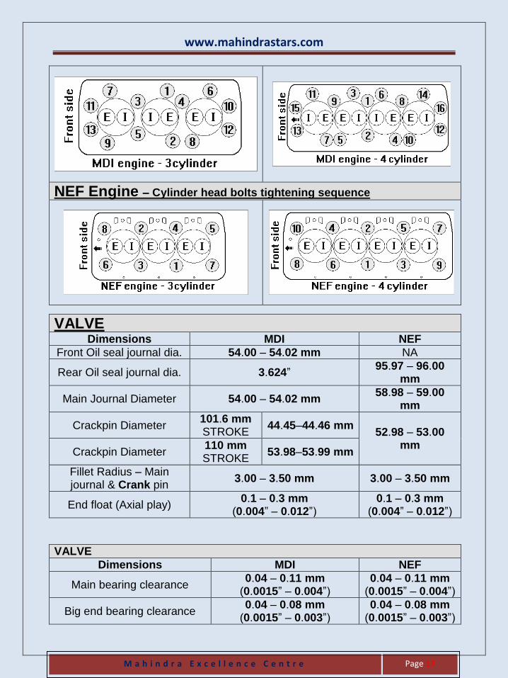
MDI Engine – Cylinder head bolts tightening sequence .................................................. 16
NEF Engine – Cylinder head bolts tightening sequence .................................................. 17
VALVE ............................................................................................................................ 17
COOLING SYSTEM ....................................................................................................... 21
CLUTCH .......................................................................................................................... 22
FRONT AXLE ................................................................................................................. 23
STEERING GEOMETRY ................................................................................................ 24
Brake ................................................................................................................................ 24
TRANSMISSION SETTINGS ......................................................................................... 25
GENERAL SPECIFICATIONS – Hydraulic System ...................................................... 26
CONTROL VALVE LEAKAGE TEST – PROCEDURE ............................................... 27
Electrical - Battery ............................................................................................................ 30
STARTER MOTOR ......................................................................................................... 30
LUBRICATION – SPECIFICATION .............................................................................. 32
Routine Maintenance Schedule – Arjun Tractor .............................................................. 33
Routine Maintenance Schedule – MDI Tractor ................................................................ 35
Routine Maintenance Schedule – MDI Tractor ................................................................ 36
ENGINE – TORQUE CHART......................................................................................... 37
HYDRAULIC – TORQUE CHART ................................................................................ 37
TRANSMISSION – TORQUE CHART .......................................................................... 38
POWER STEERING – TORQUE CHART ..................................................................... 39
www.mahindrastars.com
C h a n n e l C a r e P U & M E C , N a g p u r
Page 2
Emission norms Implementation
We are proud to declare that all engines fitted on Mahindra Tractors will be complying with Bharat Stage IIIA, also called Trem IIIA (Trem – Tractor emission) emission norms.
These Trem IIIA emission norms are more environments friendly and have been made possible by further improvisation in Engine combustion process.
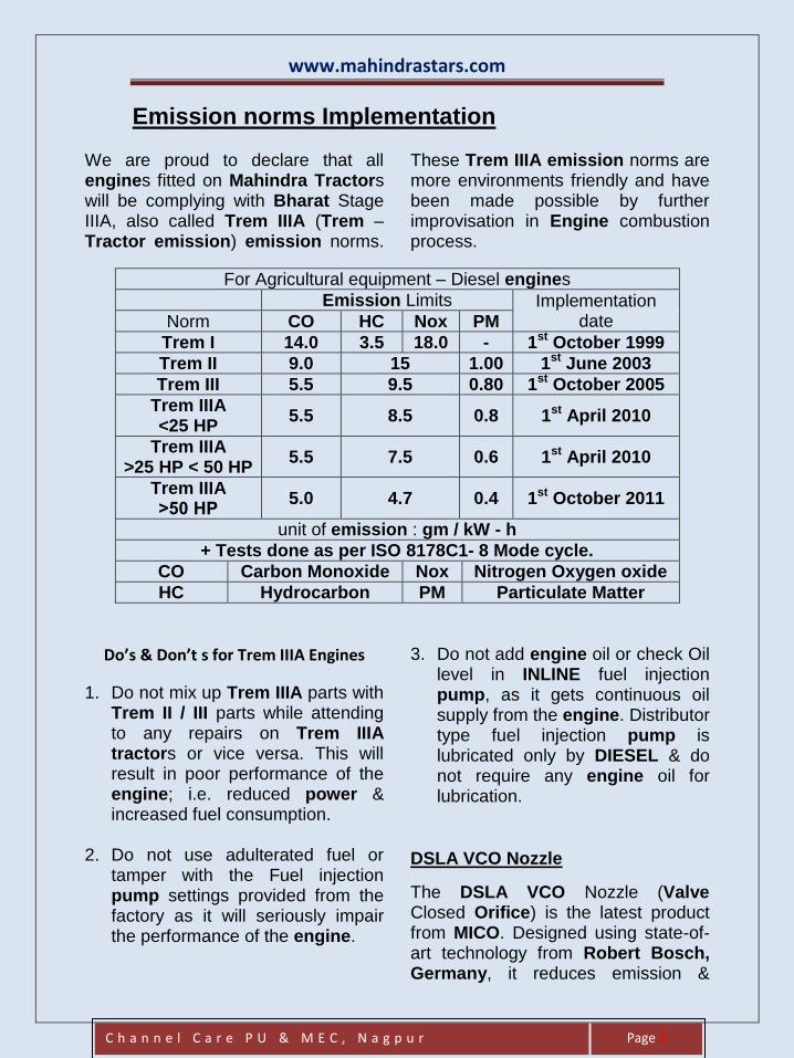
For Agricultural equipment – Diesel engines
Emission Limits Implementation date Norm CO HC Nox PM
Trem I 14.0 3.5 18.0 - 1st October 1999
Trem II 9.0 15 1.00 1st June 2003
Trem III 5.5 9.5 0.80 1st October 2005
Trem IIIA <25 HP
5.5 8.5 0.8 1st April 2010
Trem IIIA >25 HP < 50 HP
5.5 7.5 0.6 1st April 2010
Trem IIIA >50 HP
5.0 4.7 0.4 1st October 2011
unit of emission : gm / kW - h
+ Tests done as per ISO 8178C1- 8 Mode cycle.
CO Carbon Monoxide Nox Nitrogen Oxygen oxide
HC Hydrocarbon PM Particulate Matter
Do’s & Don’t s for Trem IIIA Engines
1. Do not mix up Trem IIIA parts with Trem II / III parts while attending to any repairs on Trem IIIA tractors or vice versa. This will result in poor performance of the engine; i.e. reduced power & increased fuel consumption.
2. Do not use adulterated fuel or
tamper with the Fuel injection pump settings provided from the factory as it will seriously impair the performance of the engine.
3. Do not add engine oil or check Oil level in INLINE fuel injection pump, as it gets continuous oil supply from the engine. Distributor type fuel injection pump is lubricated only by DIESEL & do not require any engine oil for lubrication.
DSLA VCO Nozzle
The DSLA VCO Nozzle (Valve Closed Orifice) is the latest product from MICO. Designed using state-of-art technology from Robert Bosch, Germany, it reduces emission &
www.mahindrastars.com
M a h i n d r a E x c e l l e n c e C e n t r e
Page 3
successfully meets stringent emission norms. Features
Soft ball profile.
Spray holes open directly into the seat.
Smaller spray holes made by Spark Erosion process.
Do’s 1. Extreme care should be taken
during removal & re-fitment into the engine.
2. Always use protection caps to cover the ball profile of the nozzle during storage & transportation.
3. Clean the nozzle using Ultrasonic Cleaning process.
Don’ts 1. Rough handling during removal &
re-fitment into the engine will lead to tip damage.
2. Do not pin the nozzle spray holes using wire as this will distort the spray holes & lead to higher emission level & smoke.
3. Do not use metallic brush or emery sheet to clean the ball profile. Scratches on the ball profile can lead to tip breakage.
Turbochargers
2005 marked the turbocharger's 100th birthday.
Turbochargers – Basics
One of the surest ways to get more power out of an engine is to increase the amount of air and fuel that it can burn. One way to do this is to add cylinders or make the current cylinders bigger. Sometimes these changes may not be feasible - a turbo
can be a simpler, more compact way to add power. A turbocharger can significantly boost an engine's horsepower without significantly increasing its weight, which is the huge benefit that makes turbo so popular. Turbochargers are a type of forced induction system. They compress the air flowing into the engine. The advantage of compressing the air is that it lets the engine squeeze more air into a cylinder, and more air means that more fuel can be added.
Therefore, you get more power from each explosion in each cylinder. A turbocharged engine produces more power overall than the same engine without the charging.
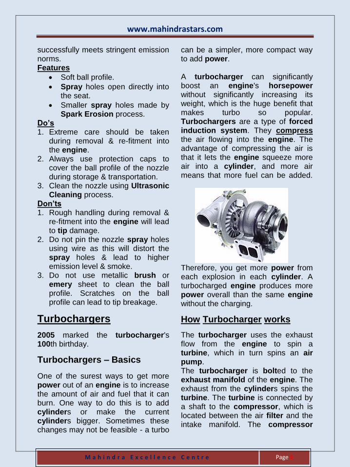
How Turbocharger works
The turbocharger uses the exhaust flow from the engine to spin a turbine, which in turn spins an air pump. The turbocharger is bolted to the exhaust manifold of the engine. The exhaust from the cylinders spins the turbine. The turbine is connected by a shaft to the compressor, which is located between the air filter and the intake manifold. The compressor
www.mahindrastars.com
M a h i n d r a E x c e l l e n c e C e n t r e
Page 4
pressurizes the air going into the pistons. The turbine in the turbocharger spins at speeds of 125,000 rotations per minute rpm & above.
Mahindra 595DI Super Turbo Tractor is the India’s first Turbo charged tractor which gives Better Power & Greater Speed.
Mahindra 295DI, 395DI Turbo & 605DI are also Turbo Charged Tractor.
Turbochargers – Do’s
1. Change Oil & Oil Filter at recommended hours of Tractor Operation.
2. Use only Castrol Prima Plus – CF4 15W40 engine oil for 595DI & 295DI. Use only CI4 15W40 engine oil for 605DI.
3. Use genuine parts (Air filter element, Engine oil filter etc.) during replacement.
4. Clean the air cleaner as recommended.
5. Use only special clamps (Uniform pressure) for all hoses.
6. Run the Tractor in low idle for 1 minute after starting the engine.
7. Run the engine at low idle for 30 seconds before stopping the Tractor.
8. If starting after a long gap, proceed as follows:
INLINE FIP – pull the “Pull to Stop” lever fully. Crank the engine 2 – 3 times without allowing the engine to start, then press the “Pull to Stop” lever and start the engine.
DISTRIBUTOR FIP – disconnect the wire from FIP solenoid so that the engine does not start. Now crank the engine 2 – 3 times (without allowing the engine to start) so that oil supply is restored. Connect the wire to FIP solenoid and start the engine.
9. In case of any problem with the turbocharger, get it checked / attended through your nearest M & M DEALER.
Turbochargers – Don’ts
Tamper with any part of the 1.turbocharger.
Allow foreign material (bolt, 2.washer etc.) to enter into turbocharger at the time of servicing / filter (Air inlet, Exhaust Outlet).
3. Hit turbocharger with any tool / parts.
4. Run the Tractor in idling for more than 10 minutes. This may cause oil leakage inside the turbocharger due to the Pressure difference.
5. Re- use the metallic gaskets.
Distributor Fuel Pump
As the Pollution norms are becoming more & more stringent, to counter Nox level, engine timing are retarded day by day. This means that the time available to deliver the fuel & allowing the fuel to mix with air is also less. To counter this, we require higher peak pressure from the pump. In general, the Inline fuel pump can generate up to a pressure of 800 bars compared to Distributor fuel pump which can generate a pressure up to 1200 bars.
www.mahindrastars.com
M a h i n d r a E x c e l l e n c e C e n t r e
Page 5
Hence Distributor fuel pump is preferred to meet higher Emission norms. The distributor type of fuel pump has a single pumping element which serves all cylinders, distribution to the individual injectors being through a rotary distributor having the required number of outlet branches. This ensures both uniformity of delivery to all injectors & in-built and exact uniformity of interval between successive injections. There are no adjustments to be made or maintained, these being inherent in the precision of manufacture. Unlike Inline fuel pump where Engine oil & diesel both lubricate the pump, the Distributor fuel pump is lubricated 100% by diesel alone. Hence filtration of diesel is very important for successful operation of Distributor fuel pump.
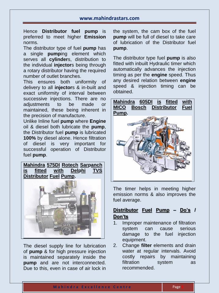
Mahindra 575DI Rotech Sarpanch is fitted with Delphi TVS Distributor Fuel Pump.
The diesel supply line for lubrication of pump & for high pressure injection is maintained separately inside the pump and are not interconnected. Due to this, even in case of air lock in
the system, the cam box of the fuel pump will be full of diesel to take care of lubrication of the Distributor fuel pump.
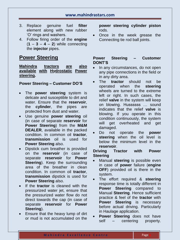
The distributor type fuel pump is also fitted with inbuilt Hydraulic timer which automatically advances the injection timing as per the engine speed. Thus any desired relation between engine speed & injection timing can be obtained.
Mahindra 605DI is fitted with MICO Bosch Distributor Fuel Pump.
The timer helps in meeting higher emission norms & also improves the fuel average.
Distributor Fuel Pump – Do’s /
Don’ts
1. Improper maintenance of filtration system can cause serious damage to the fuel injection equipment.
2. Change filter elements and drain water at regular intervals. Avoid costly repairs by maintaining filtration system as recommended.
www.mahindrastars.com
M a h i n d r a E x c e l l e n c e C e n t r e
Page 6
3. Replace genuine fuel filter element along with new rubber ‘O’ rings and washers.
4. Follow firing order of the engine (1 – 3 – 4 – 2) while connecting the injector pipes.
Power Steering
Mahindra tractors are also available with Hydrostatic Power steering.
Power Steering – Customer DO’S
The power steering system is delicate and susceptible to dirt and water. Ensure that the reservoir, the cylinder, the pipes are protected from dust and water.
Use genuine power steering oil (in case of separate reservoir for Power Steering) from the M&M DEALER, available in the packed condition. In common oil tractor, transmission oil is used for Power Steering also.
Dipstick cum breather is provided on the reservoir (in case of separate reservoir for Power Steering). Keep the surrounding area of the breather in clean condition. In common oil tractor, transmission dipstick is used for Power Steering also.
If the tractor is cleaned with the pressurized water jet, ensure that the pressurized water flow do not direct towards the cap (in case of separate reservoir for Power Steering).
Ensure that the heavy lump of dirt or mud is not accumulated on the
power steering cylinder piston rods.
Once in the week grease the Connecting tie rod ball joints.
Power Steering – Customer DONT’S
In any circumstances, do not open any pipe connections in the field or in any dirty area.
The tractor should not be operated when the steering wheels are turned to the extreme left or right. In such cases, the relief valve in the system will keep on blowing. Hussssss … sound indicates that the relief valve is blowing. If you operate in this condition continuously, the system will get overheated and get damaged.
Do not operate the power steering when the oil level is below the minimum level in the reservoir.
Driving Tractor with Power Steering
Manual steering is possible even in case of power failure (engine OFF) provided oil is there in the system.
The effort required & steering response time is totally different in Power Steering compared to Manual Steering. Hence sufficient practice & feel of the tractor with Power Steering is necessary before actual driving. Particularly in Haulage application.
Power Steering does not have self – centering property.
www.mahindrastars.com
M a h i n d r a E x c e l l e n c e C e n t r e
Page 7
Operators must understand this & practice it before actual driving. Particularly in Haulage application.
Power steering is self-bleeding system. There is no separate Bleeding Screw in the system. The system is fitted with Dipstick cum Breather.
The relief valve in the system will open at extreme left or extreme right position. The opening of relief valve follows with Hussss … sound. This is normal. If this sound appears in-between extreme left & extreme right, contact M&M DEALER.
Tips for maintaining the Hydrostatic Power Steering system.
1
Top up fluid level in Power Steering reservoir as necessary (in case of separate reservoir for Power Steering). In common oil tractor, transmission dipstick is used for Power Steering also.
2 Maintain correctly inflated tyres.
3 Always use a puller to remove the steering wheel. Do not use a hammer, torch, or crow bar.
4
Do not attempts to weld, cold Straighten, hot straighten or bend any Steering Components. Replace the components with original equipment only.
5 Investigate and correct any external leak, no matter how minor the leak is.
6
Investigate and correct immediately any play, raffle, shimmy, or other unusual occurrence in the steering
system.
7 Remove cause of steering column misalignment.
8
Encourage all drivers or operators to report any malfunction or accident that may have damaged a steering system part.
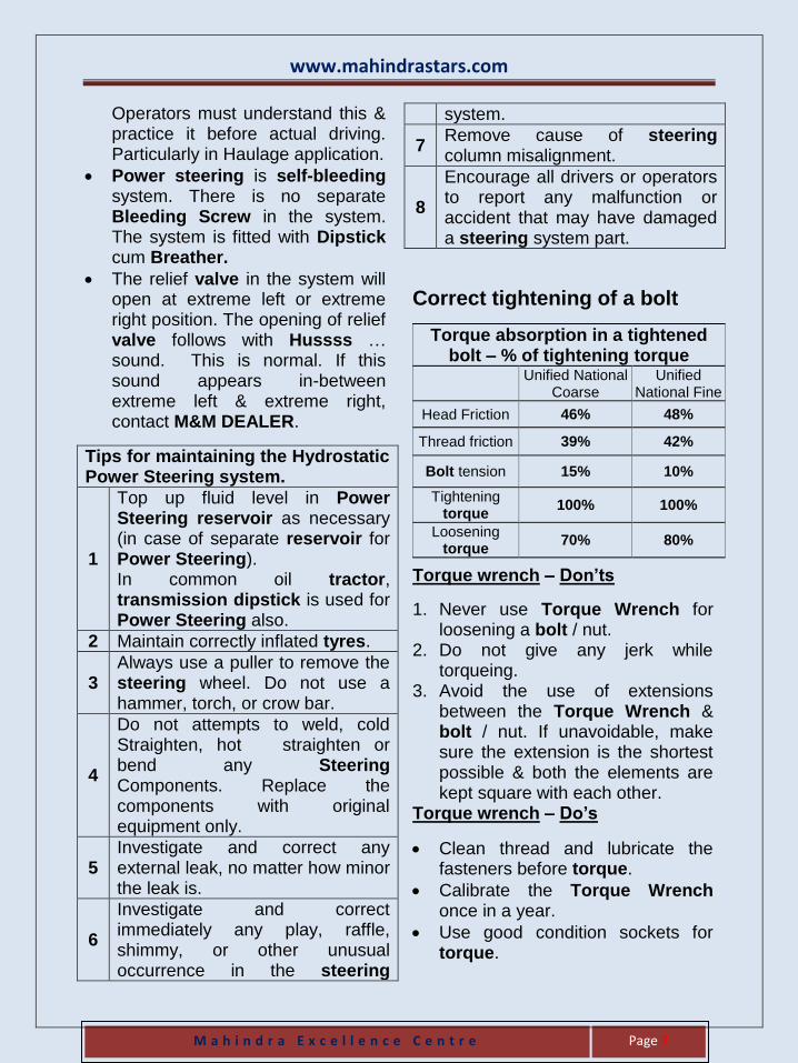
Correct tightening of a bolt
Torque absorption in a tightened bolt – % of tightening torque
Unified National
Coarse Unified
National Fine
Head Friction 46% 48%
Thread friction 39% 42%
Bolt tension 15% 10%
Tightening torque
100% 100%
Loosening torque
70% 80%
Torque wrench – Don’ts
1. Never use Torque Wrench for loosening a bolt / nut.
2. Do not give any jerk while torqueing.
3. Avoid the use of extensions between the Torque Wrench & bolt / nut. If unavoidable, make sure the extension is the shortest possible & both the elements are kept square with each other.
Torque wrench – Do’s
Clean thread and lubricate the fasteners before torque.
Calibrate the Torque Wrench once in a year.
Use good condition sockets for torque.
www.mahindrastars.com
M a h i n d r a E x c e l l e n c e C e n t r e
Page 8
For high value torque, use 6 bit socket. For higher torque values, give torque in stages.
To safeguard torque accuracy, avoid keeping the Torque Wrench set at high loads over a long period of time.
Always follow the recommended torque sequence to ensure that clamping forces are even.
EGR System Nitrous Oxide (Nox) are formed by a reaction between the Nitrogen and Oxygen in the air at high temperatures. During acceleration and in higher loads the engine generates high combustion temperatures. The high combustion temperatures increase the Nox generation. To reduce Nox :
Temperature should be lowered.
Reduce oxygen. Initial engine development efforts for reducing Nox emissions is by retarding the fuel injection timing. When no other action is taken, this results in an increase of PM emission and/or Specific fuel consumption. To avoid this the manufacturers of diesel engines have introduced increasingly advanced features such as more valves per cylinder, vertically positioned central injector, centrally located piston bowls, speed and load dependent injection timing control on higher pressure fuel injection equipment. Through these efforts it is possible to manufacture engines to meet higher
emission norms & maintaining acceptable fuel consumption levels. Exhaust gas recirculation referred to as EGR is a useful method for reducing Nox emission. Reduction of combustion temperatures - exhaust gases are inert gases with a very high value of Cp (Specific Heat at Constant Pressure) i.e. they do not take part in combustion but absorbs heat without increasing its temperature. This acts as a heat sink and reduces the overall combustion temperatures. Reduction of free oxygen inside cylinder - exhaust gases occupy some space and reduce the equivalent amount of free oxygen. Type of EGR System ■ Internal EGR – this is accomplished by changes in valve timing that allow some exhaust gas to simply remain in the cylinder and mix with the incoming air. Internal EGR is inefficient and reduces fuel economy. ■ External EGR – this is done by recirculating some exhaust gas (Exhaust Gas Recirculation) into the cylinder. External EGR are of three types : ■ non modulated – Fixed amount of exhaust gas is sent into the cylinder all the time. ■ partially modulated – Fixed amount of exhaust gas is sent into the cylinder at some specified engine rpm. No EGR at other rpm.
www.mahindrastars.com
M a h i n d r a E x c e l l e n c e C e n t r e
Page 9
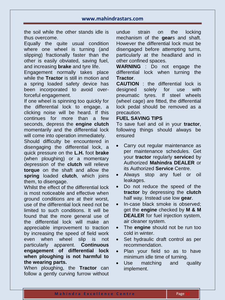
■ modulated – Variable amount of exhaust gas is sent into the cylinder at various engine rpm. EGR Cooler By recirculating exhaust gas back into the cylinders, EGR lowers the heat of combustion and thereby reduces Nox. EGR coolers further lower the temperature of the exhaust gas before recirculation, thereby achieving an even greater reduction in Nox. However, the constant use of cooled exhaust gas results in the engine taking longer to reach optimal combustion temperatures. Incomplete combustion and the associated emissions can result during that period.
New EGR cooler has a built-in bypass channel to send exhaust gases directly back to the combustion chambers when the engine temperature is low. Sensors calculate the engine temperature from the temperature of the radiator coolant, and a pressure valve opens the bypass channel whenever the temperature is below a set value. This helps the engine warm faster, reducing the time for incomplete combustion.
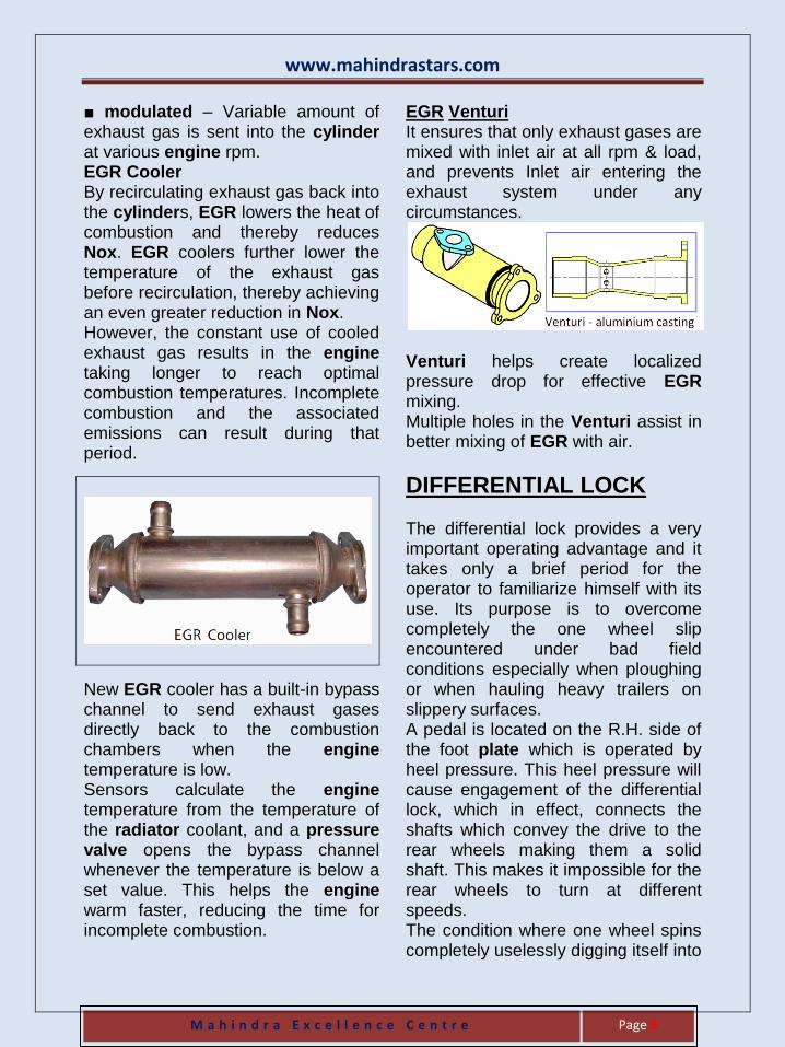
EGR Venturi It ensures that only exhaust gases are mixed with inlet air at all rpm & load, and prevents Inlet air entering the exhaust system under any circumstances.
Venturi helps create localized pressure drop for effective EGR mixing. Multiple holes in the Venturi assist in better mixing of EGR with air.
DIFFERENTIAL LOCK The differential lock provides a very important operating advantage and it takes only a brief period for the operator to familiarize himself with its use. Its purpose is to overcome completely the one wheel slip encountered under bad field conditions especially when ploughing or when hauling heavy trailers on slippery surfaces. A pedal is located on the R.H. side of the foot plate which is operated by heel pressure. This heel pressure will cause engagement of the differential lock, which in effect, connects the shafts which convey the drive to the rear wheels making them a solid shaft. This makes it impossible for the rear wheels to turn at different speeds. The condition where one wheel spins completely uselessly digging itself into
www.mahindrastars.com
M a h i n d r a E x c e l l e n c e C e n t r e
Page 10
the soil while the other stands idle is thus overcome. Equally the quite usual condition where one wheel is turning (and slipping) fractionally faster than the other is easily obviated, saving fuel, and increasing brake and tyre life. Engagement normally takes place while the Tractor is still in motion and a spring loaded safety device has been incorporated to avoid over-forceful engagement. If one wheel is spinning too quickly for the differential lock to engage, a clicking noise will be heard. If this continues for more than a few seconds, depress the engine clutch momentarily and the differential lock will come into operation immediately. Should difficulty be encountered in disengaging the differential lock, a quick pressure on the L.H. foot brake (when ploughing) or a momentary depression of the clutch will relieve torque on the shaft and allow the spring loaded clutch, which joins them, to disengage. Whilst the effect of the differential lock is most noticeable and effective when ground conditions are at their worst, use of the differential lock need not be limited to such conditions. It will be found that the more general use of the differential lock will make an appreciable improvement to traction by increasing the speed of field work even when wheel slip is not particularly apparent. Continuous engagement of differential lock when ploughing is not harmful to the wearing parts. When ploughing, the Tractor can follow a gently curving furrow without
undue strain on the locking mechanism of the gears and shaft. However the differential lock must be disengaged before attempting turns, particularly at the headland and in other confined spaces. WARNING : Do not engage the differential lock when turning the Tractor. CAUTION : the differential lock is designed solely for use with pneumatic tyres. If steel wheels (wheel cage) are fitted, the differential lock pedal should be removed as a precaution. FUEL SAVING TIPS To save fuel and oil in your tractor, following things should always be ensured
Carry out regular maintenance as per maintenance schedules. Get your tractor regularly serviced by Authorized Mahindra DEALER or its Authorized Service Centre.
Always stop any fuel or oil leakages.
Do not reduce the speed of the tractor by depressing the clutch half way. Instead use low gear.
In-case black smoke is observed; get the engine checked by M & M DEALER for fuel injection system, air cleaner system.
The engine should not be run too cold in winter.
Set hydraulic draft control as per recommendation.
Plan your field so as to have minimum idle time of turning.
Use matching and quality implement.
www.mahindrastars.com
M a h i n d r a E x c e l l e n c e C e n t r e
Page 11
Use correct gear and engine speed to get best coverage.
Keep your implement in best condition by replacing worn out parts, proper lubrication.
Proper moisture in field ensures, good ploughing and less fuel consumption.
Avoid sudden acceleration and braking of tractor.
Do not overload tractor.
Replace bald tyre. Keep proper tyre pressure.
Put adequate ballast on rear tyres for minimum slippage.
Ensure clutch does not slip or brakes are binding.
Always buy genuine spares from the authorized DEALER / distributors.
Lubricating Oil
Oil has a limited working life after which the effects of time, condensation, engine heat and by-products of combustion will combine to reduce its lubricating properties rapidly. It is therefore, incorrect to use a lubricant for more than the specified period. The intervals between lubricant changes detailed in this manual have been determined after prolonged tests and have been proved the most suitable for normal operation. In extremely arduous conditions, however, it may be necessary to reduce these periods and this point
should be discussed with Mahindra & Mahindra Ltd. or their DEALER.
Service maintenance
Without proper testing equipment, it is not possible to identify the genuine oil by touching or smelling the oil. Buy oil only from our DEALERs.
Use only recommended oil in correct quantity.
Stick to change period as mentioned.
Always change oil along with the filter.
It is highly detrimental to engine reliability, if cartridge is reused by re-flushing with cleaning solvent. Dispose off filters immediately.
It is better to change oil in warm condition.
Do not mix oil of different grade & company.
Clean the magnetic drain plug during oil change.
Change the drain plug washer during every oil change.
The supply of oil to the Inline FIP is directly from engine. No need to drain
oil from FIP or pour oil in the FIP.
However when fitting a new Inline FIP or after repair of the Inline FIP, pour
approximately 200 ml of engine oil in
the FIP before starting the engine.
We do not recommend filling the filter with engine oil during filter change. Filter should be fitted without oil. Pull the “PULL TO STOP SWITCH” & crank the engine 3 / 4 times before starting.
www.mahindrastars.com
M a h i n d r a E x c e l l e n c e C e n t r e
Page 12
Lubrication MYTH FACT
Oil change at Local garages versus at our Dealership.
Oil changes when done at a Dealership works out cheaper in long run. Our DEALER uses genuine & correct grade of oil in correct quantity, genuine filters & do a better job.
If I use superior grade oil than recommended, I can increase the drain period ?
No. In first place you should use only the recommended grade. Second, even if you use higher grade oil, the drain period will remain same.
Adding ENGINE OIL in diesel tank improved life of the fuel system.
Absolutely NO. Diesel is having lubricating properties & engine oil is not required for lubrication.
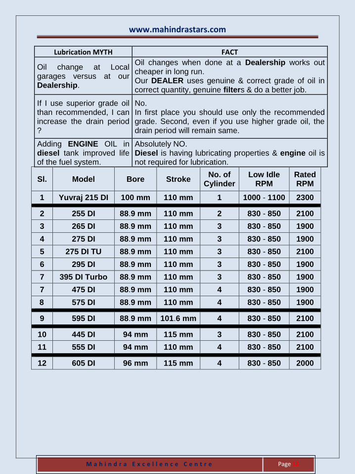
Sl. Model Bore Stroke No. of
Cylinder Low Idle
RPM Rated RPM
1 Yuvraj 215 DI 100 mm 110 mm 1 1000 - 1100 2300
2 255 DI 88.9 mm 110 mm 2 830 - 850 2100
3 265 DI 88.9 mm 110 mm 3 830 - 850 1900
4 275 DI 88.9 mm 110 mm 3 830 - 850 1900
5 275 DI TU 88.9 mm 110 mm 3 830 - 850 2100
6 295 DI 88.9 mm 110 mm 3 830 - 850 1900
7 395 DI Turbo 88.9 mm 110 mm 3 830 - 850 1900
7 475 DI 88.9 mm 110 mm 4 830 - 850 1900
8 575 DI 88.9 mm 110 mm 4 830 - 850 1900
9 595 DI 88.9 mm 101.6 mm 4 830 - 850 2100
10 445 DI 94 mm 115 mm 3 830 - 850 2100
11 555 DI 94 mm 110 mm 4 830 - 850 2100
12 605 DI 96 mm 115 mm 4 830 - 850 2000
www.mahindrastars.com
M a h i n d r a E x c e l l e n c e C e n t r e
Page 13
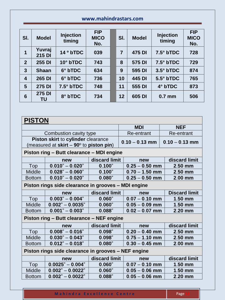
Sl. Model Injection
timing
FIP MICO No.
Sl. Model Injection timing
FIP MICO No.
1 Yuvraj 215 DI
14 º bTDC 039 7 475 DI 7.5° bTDC 728
2 255 DI 10° bTDC 743 8 575 DI 7.5° bTDC 729
3 Shaan 6° bTDC 634 9 595 DI 3.5° bTDC 874
4 265 DI 6° bTDC 736 10 445 DI 5.5° bTDC 765
5 275 DI 7.5° bTDC 748 11 555 DI 4° bTDC 873
6 275 DI
TU 8° bTDC 734 12 605 DI 0.7 mm 506
PISTON MDI NEF
Combustion cavity type Re-entrant Re-entrant
Piston skirt to cylinder clearance (measured at skirt – 90º to piston pin)
0.10 – 0.13 mm 0.10 – 0.13 mm
Piston ring – Butt clearance – MDI engine
new discard limit new discard limit
Top 0.010” – 0.020” 0.100” 0.25 – 0.50 mm 2.50 mm
Middle 0.028” – 0.060” 0.100” 0.70 – 1.50 mm 2.50 mm
Bottom 0.010” – 0.020” 0.080” 0.25 – 0.50 mm 2.00 mm
Piston rings side clearance in grooves – MDI engine
new discard limit new Discard limit
Top 0.003” – 0.004” 0.060” 0.07 – 0.10 mm 1.50 mm
Middle 0.002” – 0.0035” 0.060” 0.05 – 0.09 mm 1.50 mm
Bottom 0.001” – 0.003” 0.088” 0.02 – 0.07 mm 2.20 mm
Piston ring – Butt clearance – NEF engine
new discard limit new discard limit
Top 0.008” – 0.016” 0.098” 0.20 – 0.40 mm 2.50 mm
Middle 0.030” – 0.043” 0.098” 0.75 – 1.10 mm 2.50 mm
Bottom 0.012” – 0.018” 0.080” 0.30 – 0.45 mm 2.00 mm
Piston rings side clearance in grooves – NEF engine
new discard limit new discard limit
Top 0.0025” – 0.004” 0.060” 0.07 – 0.10 mm 1.50 mm
Middle 0.002” – 0.0022” 0.060” 0.05 – 0.06 mm 1.50 mm
Bottom 0.002” – 0.0022” 0.088” 0.05 – 0.06 mm 2.20 mm
www.mahindrastars.com
M a h i n d r a E x c e l l e n c e C e n t r e
Page 14
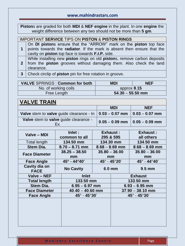
Pistons are graded for both MDI & NEF engine in the plant. In one engine the weight difference between any two should not be more than 5 gm.
IMPORTANT SERVICE TIPS ON PISTON & PISTON RINGS
1 On DI pistons ensure that the “ARROW” mark on the piston top face points towards the radiator. If the mark is absent then ensure that the cavity on piston top face is towards F.I.P. side.
2 While installing new piston rings on old pistons, remove carbon deposits from the piston grooves without damaging them. Also check the land clearance.
3 Check circlip of piston pin for free rotation in groove.
VALVE SPRINGS : Common for both MDI NEF
No. of working coils approx 8.15
Free Length 54.30 – 55.50 mm
VALVE TRAIN MDI NEF
Valve stem to valve guide clearance - In 0.03 – 0.07 mm 0.03 – 0.07 mm
Valve stem to valve guide clearance - Ex
0.05 – 0.09 mm 0.05 – 0.09 mm
Valve – MDI Inlet :
common to all Exhaust : 295 & 595
Exhaust : all others
Total length 134.50 mm 134.30 mm 134.50 mm
Stem Dia. 8.70 – 8.71 mm 8.68 – 8.69 mm 8.68 – 8.69 mm
Face Diameter 38.25 – 38.50
mm 35.80 – 36.00
mm 35.80 – 36.00
mm
Face Angle 45° - 44°40’ 45° - 45°20’ 45° - 44°40’
Cavity dia on FACE
No Cavity 6.0 mm 9.5 mm
Valve – NEF Inlet Exhaust
Total length 133.50 mm 133.50 mm
Stem Dia. 6.95 – 6.97 mm 6.93 – 6.95 mm
Face Diameter 40.40 – 40.60 mm 37.90 – 38.10 mm
Face Angle 45° - 45°30’ 45° - 45°30’
www.mahindrastars.com
M a h i n d r a E x c e l l e n c e C e n t r e
Page 15
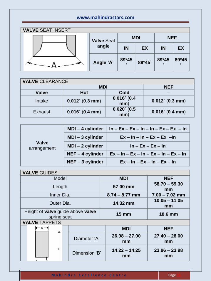
VALVE SEAT INSERT
Valve Seat angle
MDI NEF
IN EX IN EX
Angle ‘A’ 89º45
’ 89º45’
89º45’
89º45’
VALVE CLEARANCE
MDI NEF
Valve Hot Cold –
Intake 0.012” (0.3 mm) 0.016” (0.4
mm) 0.012” (0.3 mm)
Exhaust 0.016” (0.4 mm) 0.020” (0.5
mm) 0.016” (0.4 mm)
Valve arrangement
MDI – 4 cylinder In – Ex – Ex – In – In – Ex – Ex – In
MDI – 3 cylinder Ex – In – In – Ex – Ex –In
MDI – 2 cylinder In – Ex – Ex – In
NEF – 4 cylinder Ex – In – Ex – In – Ex – In – Ex – In
NEF – 3 cylinder Ex – In – Ex – In – Ex – In
VALVE GUIDES
Model MDI NEF
Length 57.00 mm 58.70 – 59.30
mm
Inner Dia. 8.74 – 8.77 mm 7.00 – 7.02 mm
Outer Dia. 14.32 mm 10.05 – 11.05
mm
Height of valve guide above valve spring seat
15 mm 18.6 mm
VALVE TAPPETS
MDI NEF
Diameter ‘A’ 26.98 – 27.00
mm 27.40 – 28.00
mm
Dimension ‘B’ 14.22 – 14.25
mm 23.96 – 23.98
mm
www.mahindrastars.com
M a h i n d r a E x c e l l e n c e C e n t r e
Page 16
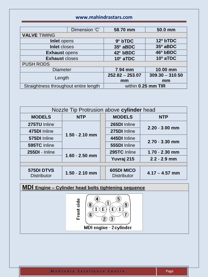
Dimension ‘C’ 58.70 mm 50.0 mm
VALVE TIMING
Inlet opens 9 bTDC 12º bTDC
Inlet closes 35 aBDC 35º aBDC
Exhaust opens 42 bBDC 46º bBDC
Exhaust closes 10 aTDC 10º aTDC
PUSH RODS
Diameter 7.94 mm 10.00 mm
Length 252.82 – 253.07
mm 309.30 – 310.50
mm
Straightness throughout entire length within 0.25 mm TIR
Nozzle Tip Protrusion above cylinder head
MODELS NTP
MODELS NTP
275TU Inline
1.50 - 2.10 mm
265DI Inline 2.20 - 3.00 mm
475DI Inline 275DI Inline
575DI Inline 445DI Inline 2.70 - 3.30 mm
595TC Inline 555DI Inline
255DI - Inline 1.60 - 2.50 mm
295TC Inline 1.70 - 2.30 mm
Yuvraj 215 2.2 - 2.9 mm
575DI DTVS Distributor
1.50 - 2.10 mm 605DI MICO Distributor
4.17 – 4.57 mm
MDI Engine – Cylinder head bolts tightening sequence
www.mahindrastars.com
M a h i n d r a E x c e l l e n c e C e n t r e
Page 17
NEF Engine – Cylinder head bolts tightening sequence
VALVE Dimensions MDI NEF
Front Oil seal journal dia. 54.00 – 54.02 mm NA
Rear Oil seal journal dia. 3.624” 95.97 – 96.00
mm
Main Journal Diameter 54.00 – 54.02 mm 58.98 – 59.00
mm
Crackpin Diameter 101.6 mm STROKE
44.45–44.46 mm 52.98 – 53.00
mm Crackpin Diameter
110 mm STROKE
53.98–53.99 mm
Fillet Radius – Main journal & Crank pin
3.00 – 3.50 mm 3.00 – 3.50 mm
End float (Axial play) 0.1 – 0.3 mm
(0.004” – 0.012”) 0.1 – 0.3 mm
(0.004” – 0.012”)
VALVE
Dimensions MDI NEF
Main bearing clearance 0.04 – 0.11 mm
(0.0015” – 0.004”) 0.04 – 0.11 mm
(0.0015” – 0.004”)
Big end bearing clearance 0.04 – 0.08 mm
(0.0015” – 0.003”) 0.04 – 0.08 mm
(0.0015” – 0.003”)
www.mahindrastars.com
M a h i n d r a E x c e l l e n c e C e n t r e
Page 18
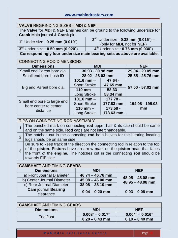
VALVE REGRINDING SIZES – MDI & NEF
The Valve for MDI & NEF Engines can be ground to the following undersize for Crank Main journal & Crank pin :
1st Under size : 0.25 mm (0.010”) 2nd Under size : 0.38 mm (0.015”) –
(only for MDI, not for NEF)
3rd Under size : 0.50 mm (0.020”) 4th Under size : 0.76 mm (0.030”)
Correspondingly four undersize main bearing sets as above are available.
CONNECTING ROD DIMENSIONS
Dimensions MDI NEF
Small end Parent bore dia. 30.93 - 30.98 mm 29.04 - 29.05 mm
Small end bore bush ID 28.02 - 28.03 mm 25.55 - 25.76 mm
Big end Parent bore dia.
101.6 mm – Short Stroke
47.64 - 47.65 mm
57.00 - 57.02 mm 110 mm –
Long Stroke 58.33 -
58.34 mm
Small end bore to large end bore center to center
distance
101.6 mm – Short Stroke
177.78 - 177.83 mm 194.08 - 195.03
mm 110 mm – Long Stroke
173.58 - 173.63 mm
TIPS ON CONNECTING ROD ASSEMBLY
1 The punched mark on connecting rod upper half & its cap should be same and on the same side. Rod caps are not interchangeable.
2 The notches cut in the connecting rod both halves for the bearing locating lugs should be on same side.
3
Be sure to keep track of the direction the connecting rod in relation to the top of the piston. Pistons have an arrow mark on the piston head that faces the front of the engine. The notches cut in the connecting rod should be towards FIP side.
CAMSHAFT AND TIMING GEARS
Dimensions MDI NEF
a) Front Journal Diameter 46.74 – 46.76 mm 48.05 – 48.08 mm 48.95 – 48.98 mm
b) Center Journal Diameter 45.08 – 46.00 mm
c) Rear Journal Diameter 38.08 – 38.10 mm
Cam journal Bearing clearance
0.04 – 0.20 mm 0.03 – 0.08 mm
CAMSHAFT AND TIMING GEARS
Dimensions MDI NEF
End float 0.008” – 0.017” 0.004” – 0.016”
0.20 – 0.43 mm 0.10 – 0.40 mm
www.mahindrastars.com
M a h i n d r a E x c e l l e n c e C e n t r e
Page 19
Max. run out on Centre journal when supported at ends
0.05 mm 0.05 mm
Idler gear end float 0.005” – 0.011” 0.004” – 0.016”
0.13 – 0.28 mm 0.10 – 0.40 mm
Backlash between Timing gears
0.004” – 0.012” 0.004” – 0.012”
0.10 – 0.30 mm 0.10 – 0.30 mm
Backlash between oil pump drive worm & drive pinion
0.002” – 0.004” 0.004” – 0.008”
0.05 – 0.10 mm 0.10 – 0.20 mm
IMPORTANT SERVICE TIPS ON CAMSHAFT
1 Ensure nominal end-float is maintained whenever repairs are undertaken.
2 Excess running clearance in camshaft & bushes or idler gear & bush can cause drop in engine oil pressure.
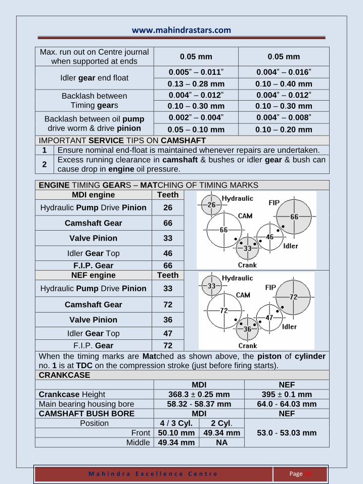
ENGINE TIMING GEARS – MATCHING OF TIMING MARKS
MDI engine Teeth
Hydraulic Pump Drive Pinion 26
Camshaft Gear 66
Valve Pinion 33
Idler Gear Top 46
F.I.P. Gear 66
NEF engine Teeth
Hydraulic Pump Drive Pinion 33
Camshaft Gear 72
Valve Pinion 36
Idler Gear Top 47
F.I.P. Gear 72
When the timing marks are Matched as shown above, the piston of cylinder no. 1 is at TDC on the compression stroke (just before firing starts).
CRANKCASE
MDI NEF
Crankcase Height 368.3 ± 0.25 mm 395 ± 0.1 mm
Main bearing housing bore 58.32 - 58.37 mm 64.0 - 64.03 mm
CAMSHAFT BUSH BORE MDI NEF
Position 4 / 3 Cyl. 2 Cyl.
53.0 - 53.03 mm Front 50.10 mm 49.34 mm
Middle 49.34 mm NA
www.mahindrastars.com
M a h i n d r a E x c e l l e n c e C e n t r e
Page 20
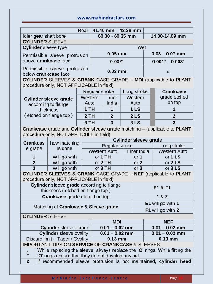
Rear 41.40 mm 43.38 mm
Idler gear shaft bore 60.30 - 60.35 mm 14.00-14.09 mm
CYLINDER SLEEVE
Cylinder sleeve type Wet
Permissible sleeve protrusion above crankcase face
0.05 mm 0.03 – 0.07 mm
0.002” 0.001” – 0.003”
Permissible sleeve protrusion below crankcase face
0.03 mm
CYLINDER SLEEVES & CRANK CASE GRADE – MDI (applicable to PLANT procedure only, NOT APPLICABLE in field)
Cylinder sleeve grade according to flange
thickness ( etched on flange top )
Regular stroke Long stroke
Crankcase grade etched
on top Western
Auto Liner India
Western Auto
1 TH 1 1 LS 1
2 TH 2 2 LS 2
3 TH 3 3 LS 3
Crankcase grade and Cylinder sleeve grade matching – (applicable to PLANT procedure only, NOT APPLICBLE in field)
Crankcase grade
how matching is done
Cylinder sleeve grade
Regular stroke Long stroke
Western Auto Liner India Western Auto
1 Will go with or 1 TH or 1 or 1 LS
2 Will go with or 2 TH or 2 or 2 LS
3 Will go with or 3 TH or 3 or 3 LS
CYLINDER SLEEVES & CRANK CASE GRADE – NEF (applicable to PLANT procedure only, NOT APPLICABLE in field)
Cylinder sleeve grade according to flange thickness ( etched on flange top )
E1 & F1
Crankcase grade etched on top 1 & 2
Matching of Crankcase & Sleeve grade E1 will go with 1
F1 will go with 2
CYLINDER SLEEVE
MDI NEF
Cylinder sleeve Taper 0.01 – 0.02 mm 0.01 – 0.02 mm
Cylinder sleeve ovality 0.01 – 0.02 mm 0.01 – 0.02 mm
Discard limit – Taper / Ovality 0.13 mm 0.13 mm
IMPORTANT TIPS ON SERVICE OF CRANKCASE & SLEEVES
1 While replacing the sleeve, always replace the ‘O’ rings. While fitting the ‘O’ rings ensure that they do not develop any cut.
2 If recommended sleeve protrusion is not maintained, cylinder head
www.mahindrastars.com
M a h i n d r a E x c e l l e n c e C e n t r e
Page 21
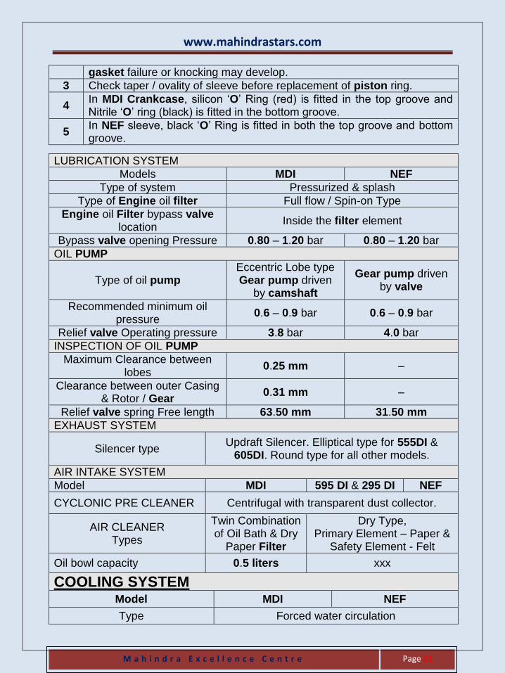
gasket failure or knocking may develop.
3 Check taper / ovality of sleeve before replacement of piston ring.
4 In MDI Crankcase, silicon ‘O’ Ring (red) is fitted in the top groove and Nitrile ‘O’ ring (black) is fitted in the bottom groove.
5 In NEF sleeve, black ‘O’ Ring is fitted in both the top groove and bottom groove.
LUBRICATION SYSTEM
Models MDI NEF
Type of system Pressurized & splash
Type of Engine oil filter Full flow / Spin-on Type
Engine oil Filter bypass valve location
Inside the filter element
Bypass valve opening Pressure 0.80 – 1.20 bar 0.80 – 1.20 bar
OIL PUMP
Type of oil pump Eccentric Lobe type Gear pump driven
by camshaft
Gear pump driven by valve
Recommended minimum oil pressure
0.6 – 0.9 bar 0.6 – 0.9 bar
Relief valve Operating pressure 3.8 bar 4.0 bar
INSPECTION OF OIL PUMP
Maximum Clearance between lobes
0.25 mm –
Clearance between outer Casing & Rotor / Gear
0.31 mm –
Relief valve spring Free length 63.50 mm 31.50 mm
EXHAUST SYSTEM
Silencer type Updraft Silencer. Elliptical type for 555DI &
605DI. Round type for all other models.
AIR INTAKE SYSTEM
Model MDI 595 DI & 295 DI NEF
CYCLONIC PRE CLEANER Centrifugal with transparent dust collector.
AIR CLEANER Types
Twin Combination of Oil Bath & Dry
Paper Filter
Dry Type, Primary Element – Paper &
Safety Element - Felt
Oil bowl capacity 0.5 liters xxx
COOLING SYSTEM Model MDI NEF
Type Forced water circulation
www.mahindrastars.com
M a h i n d r a E x c e l l e n c e C e n t r e
Page 22
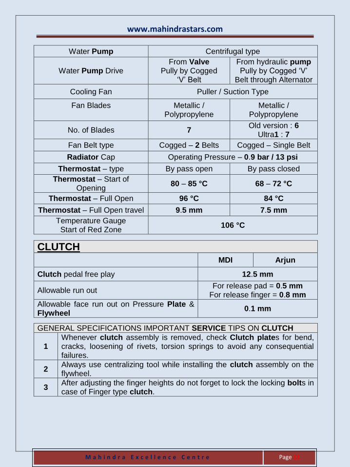
Water Pump Centrifugal type
Water Pump Drive From Valve
Pully by Cogged ‘V’ Belt
From hydraulic pump Pully by Cogged ‘V’
Belt through Alternator
Cooling Fan Puller / Suction Type
Fan Blades
Metallic / Polypropylene
Metallic / Polypropylene
No. of Blades 7 Old version : 6
Ultra1 : 7
Fan Belt type Cogged – 2 Belts Cogged – Single Belt
Radiator Cap Operating Pressure – 0.9 bar / 13 psi
Thermostat – type By pass open By pass closed
Thermostat – Start of Opening
80 – 85 °C 68 – 72 °C
Thermostat – Full Open 96 °C 84 °C
Thermostat – Full Open travel 9.5 mm 7.5 mm
Temperature Gauge Start of Red Zone
106 °C
CLUTCH
MDI Arjun
Clutch pedal free play 12.5 mm
Allowable run out For release pad = 0.5 mm
For release finger = 0.8 mm
Allowable face run out on Pressure Plate & Flywheel
0.1 mm
GENERAL SPECIFICATIONS IMPORTANT SERVICE TIPS ON CLUTCH
1 Whenever clutch assembly is removed, check Clutch plates for bend, cracks, loosening of rivets, torsion springs to avoid any consequential failures.
2 Always use centralizing tool while installing the clutch assembly on the flywheel.
3 After adjusting the finger heights do not forget to lock the locking bolts in case of Finger type clutch.
www.mahindrastars.com
M a h i n d r a E x c e l l e n c e C e n t r e
Page 23
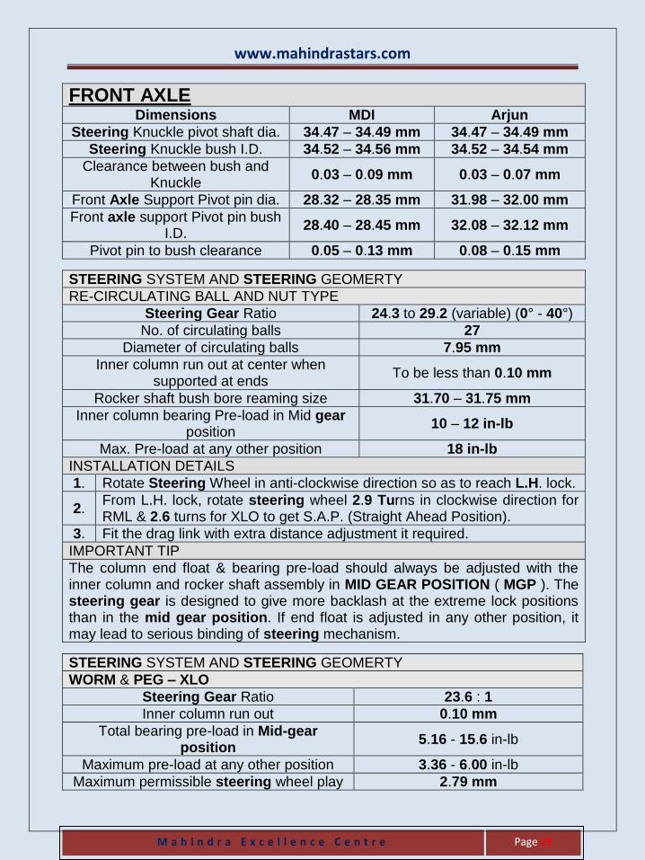
FRONT AXLE Dimensions MDI Arjun
Steering Knuckle pivot shaft dia. 34.47 – 34.49 mm 34.47 – 34.49 mm
Steering Knuckle bush I.D. 34.52 – 34.56 mm 34.52 – 34.54 mm
Clearance between bush and Knuckle
0.03 – 0.09 mm 0.03 – 0.07 mm
Front Axle Support Pivot pin dia. 28.32 – 28.35 mm 31.98 – 32.00 mm
Front axle support Pivot pin bush I.D.
28.40 – 28.45 mm 32.08 – 32.12 mm
Pivot pin to bush clearance 0.05 – 0.13 mm 0.08 – 0.15 mm
STEERING SYSTEM AND STEERING GEOMERTY
RE-CIRCULATING BALL AND NUT TYPE
Steering Gear Ratio 24.3 to 29.2 (variable) (0° - 40°)
No. of circulating balls 27
Diameter of circulating balls 7.95 mm
Inner column run out at center when supported at ends
To be less than 0.10 mm
Rocker shaft bush bore reaming size 31.70 – 31.75 mm
Inner column bearing Pre-load in Mid gear position
10 – 12 in-lb
Max. Pre-load at any other position 18 in-lb
INSTALLATION DETAILS
1. Rotate Steering Wheel in anti-clockwise direction so as to reach L.H. lock.
2. From L.H. lock, rotate steering wheel 2.9 Turns in clockwise direction for RML & 2.6 turns for XLO to get S.A.P. (Straight Ahead Position).
3. Fit the drag link with extra distance adjustment it required.
IMPORTANT TIP
The column end float & bearing pre-load should always be adjusted with the inner column and rocker shaft assembly in MID GEAR POSITION ( MGP ). The steering gear is designed to give more backlash at the extreme lock positions than in the mid gear position. If end float is adjusted in any other position, it may lead to serious binding of steering mechanism.
STEERING SYSTEM AND STEERING GEOMERTY
WORM & PEG – XLO
Steering Gear Ratio 23.6 : 1
Inner column run out 0.10 mm
Total bearing pre-load in Mid-gear position
5.16 - 15.6 in-lb
Maximum pre-load at any other position 3.36 - 6.00 in-lb
Maximum permissible steering wheel play 2.79 mm
www.mahindrastars.com
M a h i n d r a E x c e l l e n c e C e n t r e
Page 24
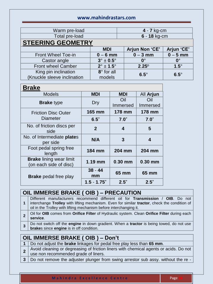
Warm pre-load 4 - 7 kg-cm
Total pre-load 6 - 18 kg-cm
STEERING GEOMETRY MDI Arjun Non ‘CE’ Arjun ‘CE’
Front Wheel Toe-in 0 – 6 mm 0 – 3 mm 0 – 5 mm
Castor angle 3° ± 0.5° 0° 0°
Front wheel Camber 2° ± 1.5° 2.25º 1.5°
King pin inclination (Knuckle sleeve inclination
8° for all models
6.5° 6.5°
Brake Models MDI MDI All Arjun
Brake type Dry Oil
Immersed Oil
Immersed
Friction Disc Outer Diameter
165 mm 178 mm 178 mm
6.5” 7.0” 7.0”
No. of friction discs per side
2 4 5
No. of Intermediate plates per side
N/A 3 4
Foot pedal spring free length
184 mm 204 mm 204 mm
Brake lining wear limit (on each side of disc)
1.19 mm 0.30 mm 0.30 mm
Brake pedal free play
38 - 44 mm
65 mm 65 mm
1.5 - 1.75” 2.5” 2.5”
OIL IMMERSE BRAKE ( OIB ) – PRECAUTION
1 Different manufacturers recommend different oil for Transmission / OIB. Do not interchange Trolley with lifting mechanism. Even for similar tractor, check the condition of oil in the Trolley with lifting mechanism before interchanging it.
2 Oil for OIB comes from Orifice Filter of Hydraulic system. Clean Orifice Filter during each service.
3 Do not switch off the engine in down gradient. When a tractor is being towed, do not use brakes since engine is in off condition.
OIL IMMERSE BRAKE ( OIB ) – Don’t 1 Do not adjust the brake linkages for pedal free play less than 65 mm.
2 Avoid cleaning or degreasing of friction liners with chemical agents or acids. Do not use non recommended grade of liners.
3 Do not remove the adjuster plunger from swing arrestor sub assy. without the re -
www.mahindrastars.com
M a h i n d r a E x c e l l e n c e C e n t r e
Page 25
setting tool. Automatic swing arrestor should not be adjusted or removed during any time other than brake liner replacement.
4 Do not switch off the engine in down gradient. When a tractor is being towed, do not use brakes since engine is in OFF condition.
OIL IMMERSE BRAKE ( OIB ) – Do
1 Ensure proper quantity & grade of oil (Tract Elf MM) in the transmission. Oil & filter should be changed at recommended period.
2 Discard limit thickness for Friction liners is 4.15 mm and less / Intermediate plate is 2.2 mm and less.
3 New friction disc must be soaked for minimum of one hour on the recommended grade of oil before fitment.
4 Intermediate plate & return spring of actuating assembly should be replaced during replacement of liners. In every brake overhauling replace gasket between end cover and housing & diff lock oil seal.
5 Brake adjustment should be done as per the SOP.
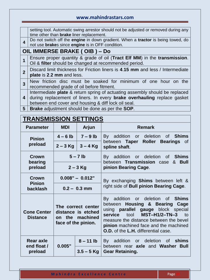
TRANSMISSION SETTINGS
Parameter MDI Arjun Remark
Pinion preload
4 – 6 lb 7 – 9 lb By addition or deletion of Shims between Taper Roller Bearings of spline shaft. 2 – 3 Kg 3 – 4 Kg
Crown bearing preload
5 – 7 lb By addition or deletion of Shims between Transmission case & Bull pinion Bearing Cage. 2 – 3 Kg
Crown Pinion
backlash
0.008" – 0.012" By exchanging Shims between left & right side of Bull pinion Bearing Cage.
0.2 – 0.3 mm
Cone Center Distance
The correct center distance is etched on the machined face of the pinion.
By addition or deletion of Shims between Housing & Bearing Cage using parallel gauge block special service tool MST–H1/2–TN–3 to measure the distance between the bevel pinion machined face and the machined O.D. of the L.H. differential case.
Rear axle end float /
preload 0.005"
8 – 11 lb By addition or deletion of shims between rear axle and Washer Bull Gear Retaining. 3.5 – 5 Kg
www.mahindrastars.com
M a h i n d r a E x c e l l e n c e C e n t r e
Page 26
Bull Pinion end float
xxx
0.0001" – 0.0015" By tightening or loosening bull cage lock
nut. 0.005 – 0.040 mm
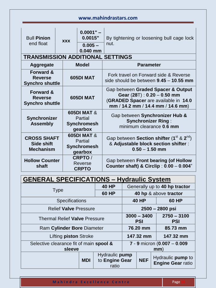
TRANSMISSION ADDITIONAL SETTINGS
Aggregate Model Parameter
Forward & Reverse
Synchro shuttle 605DI MAT
Fork travel on Forward side & Reverse side should be between 9.45 – 10.55 mm
Forward & Reverse
Synchro shuttle 605DI MAT
Gap between Graded Spacer & Output Gear (28T) : 0.20 – 0.50 mm
(GRADED Spacer are available in 14.0 mm / 14.2 mm / 14.4 mm / 14.6 mm)
Synchronizer Assembly
605DI MAT & Partial
Synchromesh gearbox
Gap between Synchronizer Hub & Synchronizer Ring :
minimum clearance 0.6 mm
CROSS SHAFT Side shift
Mechanism
605DI MAT & Partial
Synchromesh gearbox
Gap between Section shifter (1st & 2nd) & Adjustable block section shifter :
0.50 – 1.50 mm
Hollow Counter shaft
CRPTO / Reverse CRPTO
Gap between Front bearing (of Hollow Counter shaft) & Circlip : 0.00 – 0.004”
GENERAL SPECIFICATIONS – Hydraulic System
Type 40 HP Generally up to 40 hp tractor
60 HP 40 hp & above tractor
Specifications 40 HP 60 HP
Relief Valve Pressure 2500 – 2800 psi
Thermal Relief Valve Pressure 3000 – 3400
PSI 2750 – 3100
PSI
Ram Cylinder Bore Diameter 76.20 mm 85.73 mm
Lifting piston Stroke 147.32 mm 147.32 mm
Selective clearance fit of main spool & sleeve
7 - 9 micron (0.007 – 0.009 mm)
MDI Hydraulic pump to Engine Gear
ratio NEF
Hydraulic pump to Engine Gear ratio
www.mahindrastars.com
M a h i n d r a E x c e l l e n c e C e n t r e
Page 27
Hydraulic Pump Drive Pinion teeth
26 1.269
33 1.0909
Valve Pinion teeth 33 36
Three Point Linkages : Adjustable CAT - II links with outside check chains for regular models and CAT - II linkage with stabilizer bars for Arjun Models.
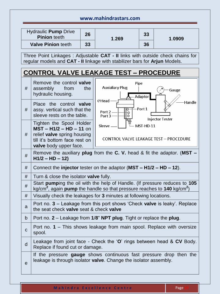
CONTROL VALVE LEAKAGE TEST – PROCEDURE
# Remove the control valve assembly from the hydraulic housing.
# Place the control valve assy. vertical such that the sleeve rests on the table.
#
Tighten the Spool Holder MST – H1/2 – HD – 11 on relief valve spring housing till it’s bottom face rest on valve body upper face.
# Remove the auxiliary plug from the C. V. head & fit the adaptor. (MST – H1/2 – HD – 12)
# Connect the injector tester on the adaptor (MST – H1/2 – HD – 12).
# Turn & close the isolator valve fully.
# Start pumping the oil with the help of Handle. (If pressure reduces to 105 kg/cm2, again pump the handle so that pressure reaches to 140 kg/cm2)
# Visually check the leakages for 3 minutes at following locations.
a Port no. 3 – Leakage from this port shows ‘Check valve is leaky’. Replace the seat check valve seat & check valve
b Port no. 2 – Leakage from 1/8" NPT plug. Tight or replace the plug.
c Port no. 1 – This shows leakage from main spool. Replace with oversize spool.
d Leakage from joint face - Check the ‘O’ rings between head & CV Body. Replace if found cut or damage.
e
If the pressure gauge shows continuous fast pressure drop then the leakage is through isolator valve. Change the isolator assembly.
www.mahindrastars.com
M a h i n d r a E x c e l l e n c e C e n t r e
Page 28
HYDRAULIC PUMP SPECIFICATIONS
Type Single Pump
Low Discharge Pump High Discharge Pump
7.03 cc/rev. of pump 11.90 cc/rev. of pump
Models Tandem Pump
Low Discharge Pump High Discharge Pump
Hitch Pum
p
Power Steering Pump
Hitch Pump
Power Steering Pump
12 cc 8 cc 18 cc 8 cc
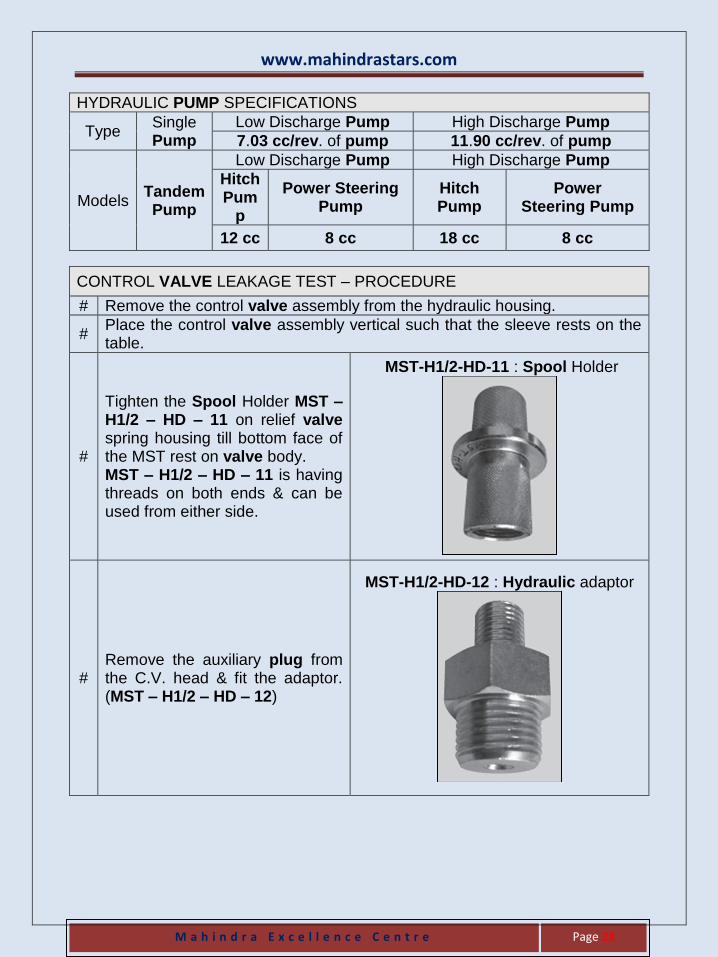
CONTROL VALVE LEAKAGE TEST – PROCEDURE
# Remove the control valve assembly from the hydraulic housing.
# Place the control valve assembly vertical such that the sleeve rests on the table.
#
Tighten the Spool Holder MST – H1/2 – HD – 11 on relief valve spring housing till bottom face of the MST rest on valve body. MST – H1/2 – HD – 11 is having threads on both ends & can be used from either side.
MST-H1/2-HD-11 : Spool Holder
# Remove the auxiliary plug from the C.V. head & fit the adaptor. (MST – H1/2 – HD – 12)
MST-H1/2-HD-12 : Hydraulic adaptor
www.mahindrastars.com
M a h i n d r a E x c e l l e n c e C e n t r e
Page 29
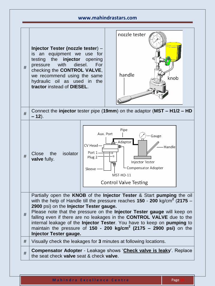
#
Injector Tester (nozzle tester) – is an equipment we use for testing the injector opening pressure with diesel. For checking the CONTROL VALVE, we recommend using the same hydraulic oil as used in the tractor instead of DIESEL.
# Connect the injector tester pipe (19mm) on the adaptor (MST – H1/2 – HD – 12).
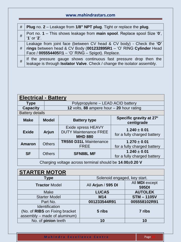
# Close the isolator valve fully.
#
Partially open the KNOB of the Injector Tester & Start pumping the oil with the help of Handle till the pressure reaches 150 - 200 kg/cm2 (2175 – 2900 psi) on the Injector Tester gauge. Please note that the pressure on the Injector Tester gauge will keep on falling even if there are no leakages in the CONTROL VALVE due to the internal leakage of the Injector Tester. You have to keep on pumping to maintain the pressure of 150 - 200 kg/cm2 (2175 – 2900 psi) on the Injector Tester gauge.
# Visually check the leakages for 3 minutes at following locations.
# Compensator Adopter - Leakage shows ‘Check valve is leaky’. Replace the seat check valve seat & check valve.
www.mahindrastars.com
M a h i n d r a E x c e l l e n c e C e n t r e
Page 30
# Plug no. 2 – Leakage from 1/8" NPT plug. Tight or replace the plug.
# Port no. 1 – This shows leakage from main spool. Replace spool Size ‘0’, ‘1’ or ‘2’.
# Leakage from joint face (between CV head & CV body) - Check the ‘O’ rings between head & CV Body (001232895R1 – ‘O’ RING Cylinder Head Face / 005554405R1 – ‘O’ RING – Spigot). Replace.
# If the pressure gauge shows continuous fast pressure drop then the leakage is through Isolator Valve. Check / change the isolator assembly.
Electrical - Battery Type Polypropylene – LEAD ACID battery
Capacity 12 volts, 88 ampere hour – 20 hour rating
Battery details
Make Model Battery type Specific gravity at 27
centigrade
Exide Arjun Exide xpress HEAVY
DUTY Maintenance FREE MHD 880
1.240 0.01 for a fully charged battery
Amaron Others TR550 D31L Maintenance
FREE 1.270 0.01
for a fully charged battery
SF Others SFN88L MF 1.240 0.01
for a fully charged battery
Charging voltage across terminal should be 14.000.20 V
STARTER MOTOR Type Solenoid engaged, key start.
Tractor Model All Arjun / 595 DI All MDI except
595DI
Make LUCAS AUTOLEK
Starter Model M14 STM – 1105V
Part No. 001233544R91 005558102R91
Identification (No. of RIBS on Fixing bracket assembly – made of aluminum)
5 ribs 7 ribs
No. of pinion teeth 10 10
www.mahindrastars.com
M a h i n d r a E x c e l l e n c e C e n t r e
Page 31
Alternator (with in-built regulator)
Max. output 36 ampere 36 ampere 36.5 ampere
Cutting in speed – maximum 1100 rpm 1100 rpm 975 rpm
Make LUCAS AUTOLEK PMP
Type Electronic Electronic Electronic
Voltage Capacity 12 V 12 V 12 V
Voltage Regulator Setting 14.1 - 14.6
volt 13.7 - 14.7
volt 14.2 - 14.4
volt
Alternator Pulley type
Bigger pulley Smaller pulley
Outer Diameter 80 mm approx.
Outer Diameter 60 mm approx.
Model
255DI with 634 FIP 255DI with 743 FIP
Shaan All 1900 rpm engines
595 DI All BS IIIA
All NEF
TYRE INFLATION PRESSURE
For Field For Road
Rear Tyre 17 psi 1.2 kg/cm2 20 psi 1.4 kg/cm2
Front Tyre 24 psi 1.7 kg/cm2 28 psi 2.0 kg/cm2
WHEEL RIM DISC AND TYRES
Rear Wheel Rim Size Rear Tyre Size Max. Run Out
W11 x 28 (6" P.C.D.) 12.4 x 28.0 4.5 mm
W11 x 28 (8" P.C.D.) 12.4 x 28.0 4.5 mm
W12 x 28 (8" P.C.D.) 13.6 x 28.0 6.5 mm
W13 x 28 (8" P.C.D.) 14.9 x 28.0 6.5 mm
W13 x 28 (8" P.C.D.) 16.9 x 28.0 6.5 mm
W13 x 28 (8" P.C.D.) 420/85 R 28 Radial tyre 6.5 mm
WHEEL RIM DISC AND TYRES
Front Wheel Rim Size Front Tyre Size Max. Run Out
W4.5 x 16 6.0 x 16.0 1.8 mm
W 5.5 x 16 7.5 x 16.0 1.8 mm
W5.0 x 20 6.5 x 20.0 1.8 mm
www.mahindrastars.com
M a h i n d r a E x c e l l e n c e C e n t r e
Page 32
LUBRICATION – SPECIFICATION
Aggregate Recommended
Lubricant Change period
Air Cleaner – Oil Bath Castrol CRB / VG 100 At every 50 hours.
Air Cleaner – Dry type
Primary Element
Clean – during every SERVICE or whenever clog indicator indicates.
Replace – during 3rd SERVICE or during 3rd cleaning.
Safety Element Replace - at the time of 3rd replacement of Primary
Element.
Aggregate Recommended
Lubricant Change period
ENGINE
All MDI engine except 295 DI & 595 DI
M Star Oil First at 250 hours along with
Filter & thereafter every 300 hours along with Filter.
595DI & 295 DI M Star Oil Every 250 hours along with
Filter.
NEF engines - 445 DI & 555 DI
M Star Oil First at 50 hours along with
Filter & thereafter every 300 hours along with Filter.
NEF engines - 605 DI
M Star Oil Replace only Filter at 50 hours & thereafter change
oil at every 300 hours along with Filter.
M Star Oil
Cooling System Mahindra Tractor Plus
Radiator Coolant 19 part Water & 1 part Coolant (by volume)
TRANSMISSION
Dryland application - NON OIB
TRACT ELF MM / Dyna Trans
Oil – at every 4th SERVICE
Wetland application - NON OIB
Castrol 140 EP Gear oil
Oil – at every 4th SERVICE
OIB (Transmission + Hydraulic + Brakes)
TRACT ELF MM / Dyna Trans
Oil – at every 4th SERVICE
Filter - at every 2nd SERVICE
COMMON OIL models (Transmission +
Hydraulic + Brakes + Power Steering)
TRACT ELF MM / Dyna Trans
Oil – at every 4th SERVICE
Filter - 1st at 50 Hours and then subsequently during
every Service.
www.mahindrastars.com
M a h i n d r a E x c e l l e n c e C e n t r e
Page 33
STEERING
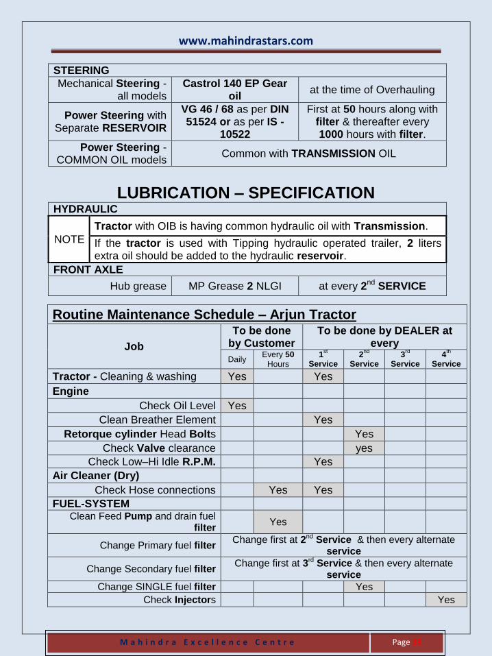
Mechanical Steering - all models
Castrol 140 EP Gear oil
at the time of Overhauling
Power Steering with Separate RESERVOIR
VG 46 / 68 as per DIN 51524 or as per IS -
10522
First at 50 hours along with filter & thereafter every 1000 hours with filter.
Power Steering - COMMON OIL models
Common with TRANSMISSION OIL
LUBRICATION – SPECIFICATION HYDRAULIC
NOTE
Tractor with OIB is having common hydraulic oil with Transmission.
If the tractor is used with Tipping hydraulic operated trailer, 2 liters extra oil should be added to the hydraulic reservoir.
FRONT AXLE
Hub grease MP Grease 2 NLGI at every 2nd SERVICE
Routine Maintenance Schedule – Arjun Tractor
Job
To be done by Customer
To be done by DEALER at every
Daily Every 50
Hours
1st
Service 2
nd
Service 3
rd
Service 4
th
Service
Tractor - Cleaning & washing Yes Yes
Engine
Check Oil Level Yes
Clean Breather Element Yes
Retorque cylinder Head Bolts Yes
Check Valve clearance
yes
Check Low–Hi Idle R.P.M. Yes
Air Cleaner (Dry)
Check Hose connections Yes Yes
FUEL-SYSTEM Clean Feed Pump and drain fuel
filter Yes
Change Primary fuel filter Change first at 2nd Service & then every alternate
service
Change Secondary fuel filter Change first at 3rd Service & then every alternate
service
Change SINGLE fuel filter Yes
Check Injectors
Yes
www.mahindrastars.com
M a h i n d r a E x c e l l e n c e C e n t r e
Page 34
Arjun Tractor Daily Every 50
Hours
1st
Service
2nd
Servic
e
3rd
Servic
e
4th
Service
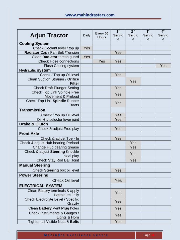
Cooling System Check Coolant level / top up Yes
Radiator Cap / Fan Belt /Tension Yes
Clean Radiator thresh guard Yes
Check Hose connections Yes Yes
Flush Cooling system Yes
Hydraulic system Check / Top up Oil level Yes
Clean Suction Strainer / Orifice Filter
Yes
Check Draft Plunger Setting Yes
Check Top Link Spindle Free Movement & Preload
Yes
Check Top Link Spindle Rubber Boots
Yes
Transmission
Check / top up Oil level Yes
Oil H-L selector lever joint Yes
Brake & Clutch Check & adjust Free play Yes
Front Axle
Check & adjust Toe - In Yes
Check & adjust Hub bearing Preload Yes
Change Hub bearing grease Yes
Check & adjust Steering Knuckle axial play
Yes
Check Stay Rod Ball Joint Yes
Manual Steering
Check Steering box oil level Yes
Power Steering
Check Oil level Yes
ELECTRICAL-SYSTEM
Clean Battery terminals & apply Petroleum Jelly
Yes
Check Electrolyte Level / Specific Gravity
Yes
Clean Battery Vent Plug holes Yes
Check Instruments & Gauges / Lights & Horn
Yes
Tighten all Visible Nuts & Bolts Yes
www.mahindrastars.com
M a h i n d r a E x c e l l e n c e C e n t r e
Page 35
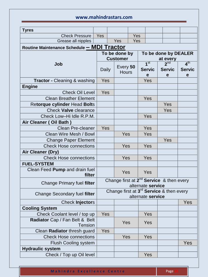
Tyres
Check Pressure Yes Yes
Grease all nipples Yes Yes
Routine Maintenance Schedule – MDI Tractor
Job
To be done by Customer
To be done by DEALER at every
Daily Every 50
Hours
1st Servic
e
2nd Servic
e
4th Servic
e
Tractor - Cleaning & washing Yes Yes Engine
Check Oil Level Yes Clean Breather Element Yes
Retorque cylinder Head Bolts Yes Check Valve clearance Yes
Check Low–Hi Idle R.P.M. Yes Air Cleaner ( Oil Bath )
Clean Pre-cleaner Yes Yes Clean Wire Mesh / Bowl Yes Yes Change Paper Element Yes
Check Hose connections Yes Yes Air Cleaner (Dry)
Check Hose connections Yes Yes FUEL-SYSTEM
Clean Feed Pump and drain fuel filter
Yes Yes
Change Primary fuel filter Change first at 2nd Service & then every
alternate service
Change Secondary fuel filter Change first at 3rd Service & then every
alternate service
Check Injectors Yes Cooling System
Check Coolant level / top up Yes Yes Radiator Cap / Fan Belt & Belt
Tension Yes Yes
Clean Radiator thresh guard Yes Check Hose connections Yes Yes
Flush Cooling system Yes Hydraulic system
Check / Top up Oil level Yes
www.mahindrastars.com
M a h i n d r a E x c e l l e n c e C e n t r e
Page 36
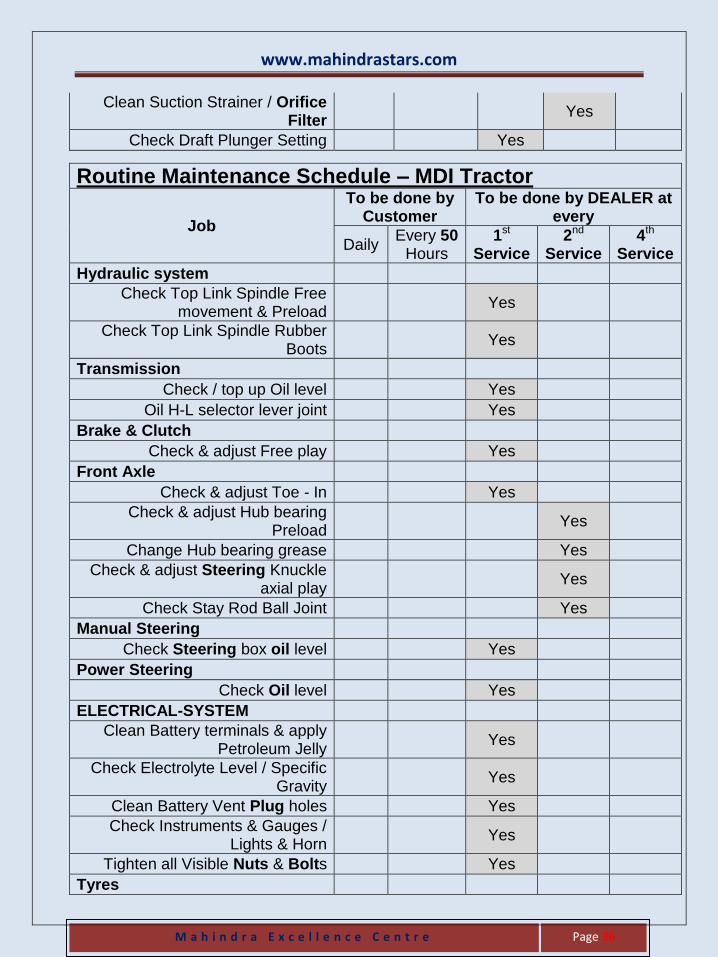
Clean Suction Strainer / Orifice Filter
Yes
Check Draft Plunger Setting Yes
Routine Maintenance Schedule – MDI Tractor
Job
To be done by Customer
To be done by DEALER at every
Daily Every 50
Hours 1st
Service 2nd
Service 4th
Service
Hydraulic system Check Top Link Spindle Free
movement & Preload Yes
Check Top Link Spindle Rubber Boots
Yes
Transmission Check / top up Oil level Yes
Oil H-L selector lever joint Yes Brake & Clutch
Check & adjust Free play Yes Front Axle
Check & adjust Toe - In Yes Check & adjust Hub bearing
Preload Yes
Change Hub bearing grease Yes Check & adjust Steering Knuckle
axial play Yes
Check Stay Rod Ball Joint Yes Manual Steering
Check Steering box oil level Yes Power Steering
Check Oil level Yes ELECTRICAL-SYSTEM
Clean Battery terminals & apply Petroleum Jelly
Yes
Check Electrolyte Level / Specific Gravity
Yes
Clean Battery Vent Plug holes Yes Check Instruments & Gauges /
Lights & Horn Yes
Tighten all Visible Nuts & Bolts Yes Tyres
www.mahindrastars.com
M a h i n d r a E x c e l l e n c e C e n t r e
Page 37
Check Pressure Yes Grease all nipples Yes Yes
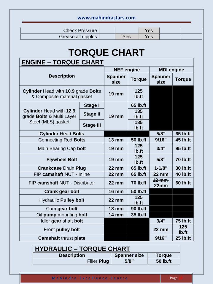
TORQUE CHART ENGINE – TORQUE CHART
Description
NEF engine MDI engine
Spanner size
Torque Spanner
size Torque
Cylinder Head with 10.9 grade Bolts & Composite material gasket
19 mm 125 lb.ft
Cylinder Head with 12.9 grade Bolts & Multi Layer
Steel (MLS) gasket
Stage I
19 mm
65 lb.ft
Stage II 135 lb.ft
Stage III 185 lb.ft
Cylinder Head Bolts
5/8” 65 lb.ft
Connecting Rod Bolts 13 mm 50 lb.ft 9/16” 45 lb.ft
Main Bearing Cap bolt 19 mm 125 lb.ft
3/4" 95 lb.ft
Flywheel Bolt 19 mm 125 lb.ft
5/8” 70 lb.ft
Crankcase Drain Plug 22 mm 65 lb.ft 1-1/8” 30 lb.ft
FIP camshaft NUT - Inline 22 mm 65 lb.ft 22 mm 40 lb.ft
FIP camshaft NUT - Distributor 22 mm 70 lb.ft 12 mm 22mm
60 lb.ft
Crank gear bolt 16 mm 50 lb.ft
Hydraulic Pulley bolt 22 mm 125 lb.ft
Cam gear bolt 18 mm 90 lb.ft
Oil pump mounting bolt 14 mm 35 lb.ft
Idler gear shaft bolt
3/4" 75 lb.ft
Front pulley bolt
22 mm 125 lb.ft
Camshaft thrust plate
9/16” 25 lb.ft
HYDRAULIC – TORQUE CHART Description Spanner size Torque
Filler Plug 5/8” 50 lb.ft
www.mahindrastars.com
M a h i n d r a E x c e l l e n c e C e n t r e
Page 38
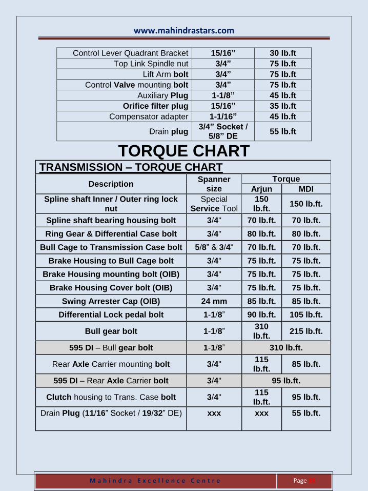
Control Lever Quadrant Bracket 15/16” 30 lb.ft
Top Link Spindle nut 3/4” 75 lb.ft
Lift Arm bolt 3/4” 75 lb.ft
Control Valve mounting bolt 3/4” 75 lb.ft
Auxiliary Plug 1-1/8” 45 lb.ft
Orifice filter plug 15/16” 35 lb.ft
Compensator adapter 1-1/16” 45 lb.ft
Drain plug 3/4” Socket /
5/8” DE 55 lb.ft
TORQUE CHART TRANSMISSION – TORQUE CHART
Description Spanner
size
Torque
Arjun MDI
Spline shaft Inner / Outer ring lock nut
Special Service Tool
150 lb.ft.
150 lb.ft.
Spline shaft bearing housing bolt 3/4" 70 lb.ft. 70 lb.ft.
Ring Gear & Differential Case bolt 3/4" 80 lb.ft. 80 lb.ft.
Bull Cage to Transmission Case bolt 5/8” & 3/4" 70 lb.ft. 70 lb.ft.
Brake Housing to Bull Cage bolt 3/4" 75 lb.ft. 75 lb.ft.
Brake Housing mounting bolt (OIB) 3/4" 75 lb.ft. 75 lb.ft.
Brake Housing Cover bolt (OIB) 3/4" 75 lb.ft. 75 lb.ft.
Swing Arrester Cap (OIB) 24 mm 85 lb.ft. 85 lb.ft.
Differential Lock pedal bolt 1-1/8” 90 lb.ft. 105 lb.ft.
Bull gear bolt 1-1/8” 310 lb.ft.
215 lb.ft.
595 DI – Bull gear bolt 1-1/8” 310 lb.ft.
Rear Axle Carrier mounting bolt 3/4" 115 lb.ft.
85 lb.ft.
595 DI – Rear Axle Carrier bolt 3/4" 95 lb.ft.
Clutch housing to Trans. Case bolt 3/4" 115 lb.ft.
95 lb.ft.
Drain Plug (11/16” Socket / 19/32” DE) xxx xxx 55 lb.ft.
www.mahindrastars.com
M a h i n d r a E x c e l l e n c e C e n t r e
Page 39
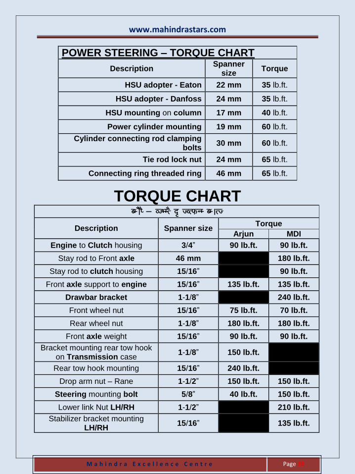
POWER STEERING – TORQUE CHART
Description Spanner
size Torque
HSU adopter - Eaton 22 mm 35 lb.ft.
HSU adopter - Danfoss 24 mm 35 lb.ft.
HSU mounting on column 17 mm 40 lb.ft.
Power cylinder mounting 19 mm 60 lb.ft.
Cylinder connecting rod clamping bolts
30 mm 60 lb.ft.
Tie rod lock nut 24 mm 65 lb.ft.
Connecting ring threaded ring 46 mm 65 lb.ft.
TORQUE CHART
CHASSIS & OTHERS – TORQUE CHART
Description Spanner size Torque
Arjun MDI
Engine to Clutch housing 3/4” 90 lb.ft. 90 lb.ft.
Stay rod to Front axle 46 mm 180 lb.ft.
Stay rod to clutch housing 15/16” 90 lb.ft.
Front axle support to engine 15/16” 135 lb.ft. 135 lb.ft.
Drawbar bracket 1-1/8” 240 lb.ft.
Front wheel nut 15/16” 75 lb.ft. 70 lb.ft.
Rear wheel nut 1-1/8” 180 lb.ft. 180 lb.ft.
Front axle weight 15/16” 90 lb.ft. 90 lb.ft.
Bracket mounting rear tow hook on Transmission case
1-1/8” 150 lb.ft.
Rear tow hook mounting 15/16” 240 lb.ft.
Drop arm nut – Rane 1-1/2” 150 lb.ft. 150 lb.ft.
Steering mounting bolt 5/8” 40 lb.ft. 150 lb.ft.
Lower link Nut LH/RH 1-1/2” 210 lb.ft.
Stabilizer bracket mounting LH/RH
15/16” 135 lb.ft.
www.mahindrastars.com
M a h i n d r a E x c e l l e n c e C e n t r e
Page 40
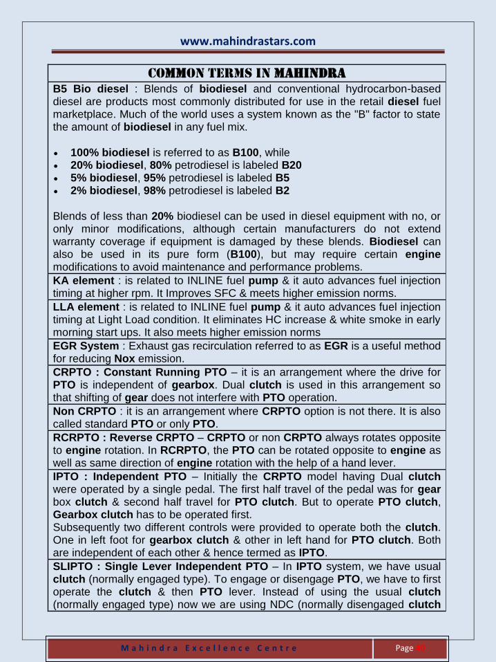
Common terms in MAHINDRA
B5 Bio diesel : Blends of biodiesel and conventional hydrocarbon-based diesel are products most commonly distributed for use in the retail diesel fuel marketplace. Much of the world uses a system known as the "B" factor to state the amount of biodiesel in any fuel mix.
100% biodiesel is referred to as B100, while 20% biodiesel, 80% petrodiesel is labeled B20 5% biodiesel, 95% petrodiesel is labeled B5 2% biodiesel, 98% petrodiesel is labeled B2
Blends of less than 20% biodiesel can be used in diesel equipment with no, or only minor modifications, although certain manufacturers do not extend warranty coverage if equipment is damaged by these blends. Biodiesel can also be used in its pure form (B100), but may require certain engine modifications to avoid maintenance and performance problems.
KA element : is related to INLINE fuel pump & it auto advances fuel injection timing at higher rpm. It Improves SFC & meets higher emission norms.
LLA element : is related to INLINE fuel pump & it auto advances fuel injection timing at Light Load condition. It eliminates HC increase & white smoke in early morning start ups. It also meets higher emission norms
EGR System : Exhaust gas recirculation referred to as EGR is a useful method for reducing Nox emission.
CRPTO : Constant Running PTO – it is an arrangement where the drive for PTO is independent of gearbox. Dual clutch is used in this arrangement so that shifting of gear does not interfere with PTO operation.
Non CRPTO : it is an arrangement where CRPTO option is not there. It is also called standard PTO or only PTO.
RCRPTO : Reverse CRPTO – CRPTO or non CRPTO always rotates opposite to engine rotation. In RCRPTO, the PTO can be rotated opposite to engine as well as same direction of engine rotation with the help of a hand lever.
IPTO : Independent PTO – Initially the CRPTO model having Dual clutch were operated by a single pedal. The first half travel of the pedal was for gear box clutch & second half travel for PTO clutch. But to operate PTO clutch, Gearbox clutch has to be operated first. Subsequently two different controls were provided to operate both the clutch. One in left foot for gearbox clutch & other in left hand for PTO clutch. Both are independent of each other & hence termed as IPTO.
SLIPTO : Single Lever Independent PTO – In IPTO system, we have usual clutch (normally engaged type). To engage or disengage PTO, we have to first operate the clutch & then PTO lever. Instead of using the usual clutch (normally engaged type) now we are using NDC (normally disengaged clutch
www.mahindrastars.com
M a h i n d r a E x c e l l e n c e C e n t r e
Page 41
type) in some of the models (605 MAT). In this arrangement there is no PTO lever & to engage / disengage PTO, we have to operate the clutch lever only. They are called SLIPTO.
Common Oil tractor : There are the tractors having separate oil for Hydraulic, Transmission & Power Steering. Also there are the tractors having common oil for Hydraulic, Transmission & OIB but separate oil for Power Steering. Common Oil tractors are the tractors having common oil for Hydraulic, Transmission, OIB & Power Steering.
Rationalize Gear box : The Tractor speed in gear L4 is less than in gear H1.
Overlap Gearbox : The Tractor speed in gear L4 is more than in gear H1.
High torque (Overlap) Transmission : variant of the Arjun transmission having Higher TORQUE & lesser SPEED. Tractor speed in gear L4 is more than in gear H1.
High Speed (rationalize) Transmission : variant of the Arjun transmission having Higher SPEED & lesser TORQUE. Tractor speed in gear L4 is less than in gear H1.
PCM : Partial Constant mesh – all Gears are in Constant mesh except First & Reverse Gear which are in Sliding mesh.
Partial Synchromesh : Partial Synchromesh – all Gears are in Constant mesh except 3rd & 4th gear which are in Synchromesh.
SPLINE SHAFT : The gearbox main shaft & Pinion shaft of the Crown Wheel Pinion are two separate parts in most of the automobiles & are connected by a propeller shaft. In tractor, main shaft & pinion shaft are a single unit called SPLINE shaft.
CONE CENTRE DISTANCE : The mounting distance between the Crown Wheel & Pinion.
‘SET OF TWO’ : Crown Wheel & Pinion.
‘SET OF FOUR’ : In older Sliding mesh gearbox, four components related to QUILL gear - Coupling Gear, GEAR, Quill GEAR & Coupling.
LIVE hydraulic : The hydraulic pump is attached to the engine so that hydraulic is ready to work as soon as the engine starts irrespective of clutch – engaged or disengaged.
Thermal Relief Valve : A pressure relief (single / double) valve provided on the hydraulic piston.
www.mahindrastars.com
M a h i n d r a E x c e l l e n c e C e n t r e
Page 42
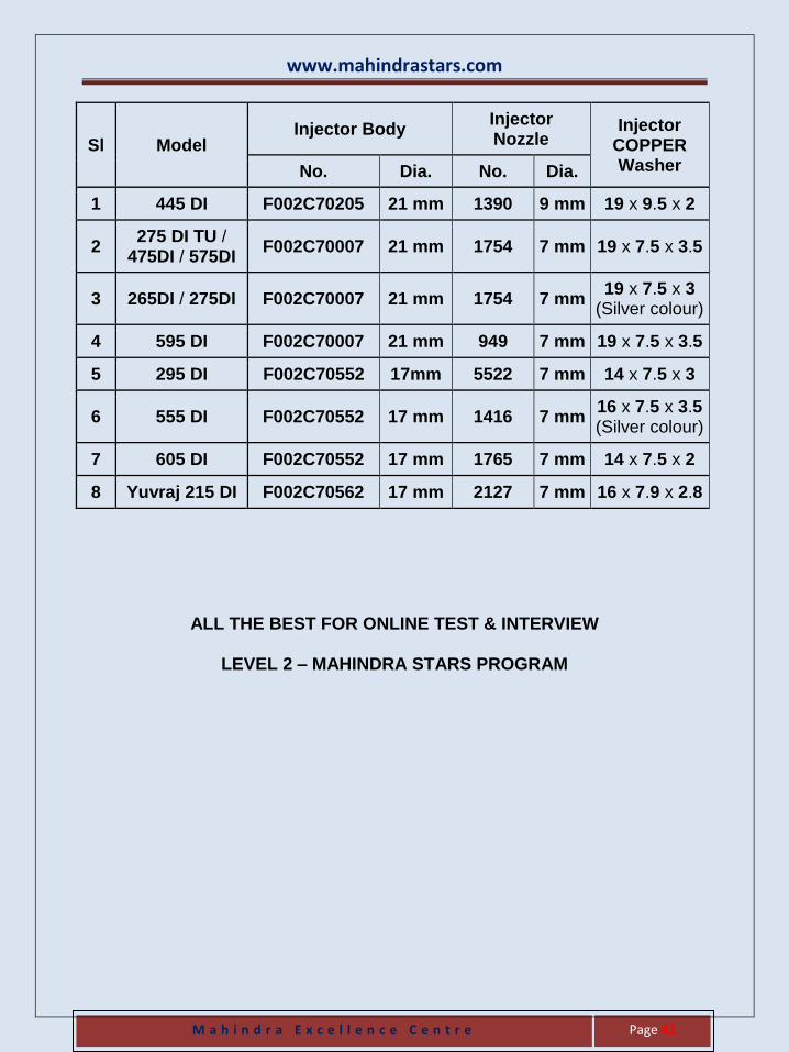
Sl Model Injector Body
Injector Nozzle
Injector COPPER Washer No. Dia. No. Dia.
1 445 DI F002C70205 21 mm 1390 9 mm 19 x 9.5 x 2
2 275 DI TU /
475DI / 575DI F002C70007 21 mm 1754 7 mm 19 x 7.5 x 3.5
3 265DI / 275DI F002C70007 21 mm 1754 7 mm 19 x 7.5 x 3
(Silver colour)
4 595 DI F002C70007 21 mm 949 7 mm 19 x 7.5 x 3.5
5 295 DI F002C70552 17mm 5522 7 mm 14 x 7.5 x 3
6 555 DI F002C70552 17 mm 1416 7 mm 16 x 7.5 x 3.5 (Silver colour)
7 605 DI F002C70552 17 mm 1765 7 mm 14 x 7.5 x 2
8 Yuvraj 215 DI F002C70562 17 mm 2127 7 mm 16 x 7.9 x 2.8
ALL THE BEST FOR ONLINE TEST & INTERVIEW
LEVEL 2 – MAHINDRA STARS PROGRAM