rear traction bar system - bds suspension traction bar system rev. 01092014. part#: 122617, 122618....
TRANSCRIPT
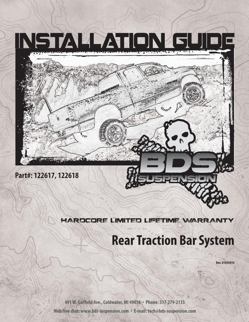
Rear Traction Bar SystemRev. 01092014
Part#: 122617, 122618
491 W. Garfield Ave., Coldwater, MI 49036 . Phone: 517-279-2135
Web/live chat: www.bds-suspension.com . E-mail: [email protected]

2 | 122617, 122618
Read And Understand All Instructions And Warnings Prior To Installation Of
System And Operation Of Vehicle.
BEFORE YOU STARTBDS Suspension Co. recommends this system be installed by a professional technician. In addition to these instructions, professional knowledge of disassembly/ reassembly procedures and post installation checks must be known.
FOR YOUR SAFETYCertain BDS Suspension products are intended to improve off-road per-formance. Modifying your vehicle for off-road use may result in the vehicle handling differently than a factory equipped vehicle. Extreme care must be used to prevent loss of control or vehicle rollover. Failure to drive your modified vehicle safely may result in serious injury or death. BDS Suspension Co. does not recommend the combined use of suspension lifts, body lifts, or other lifting devices. You should never operate your modified vehicle under the influence of alcohol or drugs. Always drive your modified vehicle at re-duced speeds to ensure your ability to control your vehicle under all driving conditions. Always wear your seat belt.
BEFORE INSTALLATIONSpecial literature required: OE Service Manual for model/year of vehicle. Refer to manual for proper disassembly/reassembly procedures of OE and related components.
Adhere to recommendations when replacement fasteners, retainers and keepers are called out in the OE manual.
Larger rim and tire combinations may increase leverage on suspension, steering, and related components. When selecting combinations larger than OE, consider the additional stress you could be inducing on the OE and related components.
Post suspension system vehicles may experience drive line vibrations. Angles may require tuning, slider on shaft may require replacement, shafts may need to be lengthened or trued, and U-joints may need to be replaced.
Secure and properly block vehicle prior to installation of BDS Suspension components. Always wear safety glasses when using power tools.
If installation is to be performed without a hoist, BDS Suspension Co. recom-mends rear alterations first.
Due to payload options and initial ride height variances, the amount of lift is a base figure. Final ride height dimensions may vary in accordance to original vehicle attitude. Always measure the attitude prior to beginning installation.
Your truck is about to be fitted with the best suspension system on the market today. That means you will be driving the baddest looking truck in the neighborhood, and you’ll have the warranty to ensure that it stays that way for years to come.
Thank you for choosing BDS Suspension!
BEFORE YOU DRIVECheck all fasteners for proper torque. Check to ensure for adequate clearance between all rotating, mobile, fixed, and heated members. Verify clearance between exhaust and brake lines, fuel lines, fuel tank, floor boards and wiring harness. Check steering gear for clearance. Test and inspect brake system.
Perform steering sweep to ensure front brake hoses have adequate slack and do not contact any rotating, mobile or heated members. Inspect rear brake hoses at full extension for adequate slack. Failure to perform hose check/ replacement may result in component failure. Longer replacement hoses, if needed can be purchased from a local parts supplier.
Perform head light check and adjustment.
Re-torque all fasteners after 500 miles. Always inspect fasteners and compo-nents during routine servicing.

122617, 122618 | 3
122617, 122618
Part # Qty Description
01805-1 2 54" Traction Bar
01802-1 2 Axle Mount (#122617)
01810-1 2 Axle Mount (#122618)
01803-1 2 Traction Bar MT
M02016RB 4 Large Shock Eye-Royal Blue
54587-1 4 3/4" x .090" x 1.575 Sleeve
123120412R 2 1/2" x 3-1/2" x 4-1/2" Round U-Bolt (#122617)
123780500R 2 1/2" x 3-7/8" x 5" Round U-bolt (#122618)
95105A159 7 Rivet nut - 3/8" x 0.150
122617, 122618
342701 1 Loctite
803 1 Bolt Pack
6 3/8"-16 x 1-1/4" bolt
4 1/2" SAE flat washer
4 1/2"-20 prevailing torque nut
4 9/16"-12 x 3" bolt
4 9/16"-12 prevailing torque nut
8 9/16" SAE flat washer
TROUBLESHOOTING INFORMATION FOR YOUR VEHICLE1. Must be installed with a 4” or taller suspension lift.
INSTALLATION INSTRUCTIONS1. Park the vehicle on a clean, flat surface and block the rear wheels for safety.
This install must be performed with the rear axle at ride height (i.e. do not raise the vehicle and allow the rear axle to hang).
2. Lightly grease and install the provided hourglass bushings (M02016BK) and sleeves (54587) in the ends of the new traction bars (01805). (Fig 1)
4 | 122617, 122618
FIGURE 1
Complete the following installation on one side of the vehicle at a time.
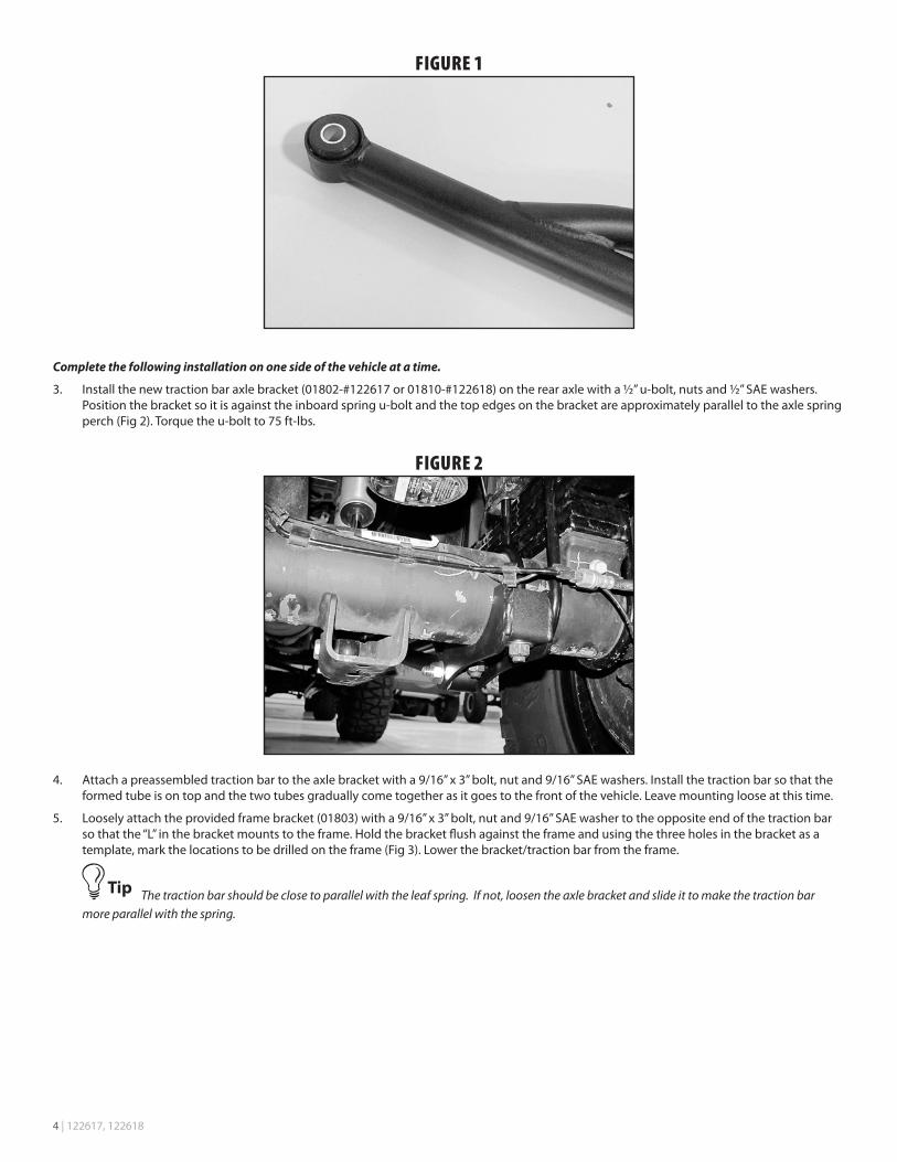
3. Install the new traction bar axle bracket (01802-#122617 or 01810-#122618) on the rear axle with a ½” u-bolt, nuts and ½” SAE washers. Position the bracket so it is against the inboard spring u-bolt and the top edges on the bracket are approximately parallel to the axle spring perch (Fig 2). Torque the u-bolt to 75 ft-lbs.
FIGURE 2
4. Attach a preassembled traction bar to the axle bracket with a 9/16” x 3” bolt, nut and 9/16” SAE washers. Install the traction bar so that the formed tube is on top and the two tubes gradually come together as it goes to the front of the vehicle. Leave mounting loose at this time.
5. Loosely attach the provided frame bracket (01803) with a 9/16” x 3” bolt, nut and 9/16” SAE washer to the opposite end of the traction bar so that the “L” in the bracket mounts to the frame. Hold the bracket flush against the frame and using the three holes in the bracket as a template, mark the locations to be drilled on the frame (Fig 3). Lower the bracket/traction bar from the frame.
The traction bar should be close to parallel with the leaf spring. If not, loosen the axle bracket and slide it to make the traction bar more parallel with the spring.

122617, 122618 | 5
FIGURE 3
6. Drill 17/32” (0.531”) holes at each of the three marks on the frame.
Only drill through the one side of the boxed frame rail. A step drill is highly recommended.
7. Insert the rivet nut into the hole as shown with 3/8” x 1-1/2” bolt with 7/16” high nut and serrated edge washer. Place a wrench on the high nut and tighten the 3/8” bolt until the rivet nut seats. Repeat for each hole. There is once extra rivet nut included with the kit if one is installed incorrectly. See detailed rivet nut installation instructions at the end of this instruction sheet.
8. Place the bracket up to the frame and align the holes with the newly drilled holes in the frame. Attach with 3/8” x 1-1/4” hardware. Torque the 3/8” bolts to 30 ft-lbs.
9. With both traction bar brackets installed, torque the two 9/16” bolts to 90 ft-lbs.
10. Repeat installation on the other side of the vehicle
11. Check for proper clearance of the bar if the suspension is compressed. On vehicles with 2” of lift or less it may be necessary to flip the bars to gain adequate clearance. Some vehicle have nut tabs at the spring perches that need to be formed out of the way for clearance.
12. Check all hardware for proper torque.
While this system was designed and tested as a “bolt-on” kit, the axle bracket can also be tack welded to the axle tube. This would only be necessary if increased torque/leverage was consistantly applied over the normal loads.
13. Check hardware after 500 miles.

6 | 122617, 122618
RIVET NUT INSTALLATION INSTRUCTIONS
RIVET NUT SIZING1. Verify the correct size rivet nut for the application based on the thickness of material where the rivet nut is to be installed using the follow-
ing chart.
Part
Number
Thread
Size
Body
Length (in)
Material Thickness
(in)
Drill
Size (in)Min. Max.
95105A159 3/8-16 .690 .027 .150 17/32
95105A168 3/8-16 .805 .150 .312 17/32
95105A169 1/2-13 1.150 .063 .200 11/16
95105A170 1/2-13 1.300 .200 .350 11/16
HOLE PREPARATION2. Drill hole to appropriate size for rivet nut installation. 1/2” Rivnuts require an 11/16” hole and 3/8” Rivnuts require a 17/32” drill. It is critical
that this hole is drilled to the correct size. Remove any burrs that could keep the rivet nut from seating flat against either side of the hole surface.
If the correct drill size is not available, it is possible to drill the hole to an available smaller size and slowly grind it out to until the rivet nut fits tight.
RIVET NUT INSTALLATION TOOL ASSEMBLY3. For a 3/8” rivet nut, place the provided 3/8” SAE flat washer on the 3/8” x 1-1/2” bolt, followed by 7/16” hex nut and then a 3/8” serrated
washer. Figure 1 Thread this tool assembly into the rivet nut.
4. For a 1/2” rivet nut, place the provided 1/2” SAE washer on a 1/2” x 2” bolt followed by a 9/16” high nut and 1/2” serrated edge lock washer. Thread this tool assembly into the rivet nut as shown. (Fig. 1)
FIGURE 1 - 1/2” RIVET NUT SHOWN
.
RIVET NUT INSTALLATION5. Place the installation tool with the rivet nut threaded on the end into the appropriately sized hole.
6. For a 3/8” rivet nut, hold the nut closest to the rivet nut still with an 5/8” wrench and tighten the 3/8” bolt with a 9/16 wrench to set the rivet nut. Be sure to hold the rivet nut flush to the surface and square to the hole as it is tightened. (Fig. 2)

122617, 122618 | 7
If available, an impact gun is recommended for tightening the bolt to ensure the rivet nut remains square to the hole and to ease hold-ing the nut from spinning.
7. For a 1/2” rivet nut, hold the nut closest to the rivet nut still with an 7/8” wrench and tighten the 1/2” bolt with a 3/4” wrench to set the rivet nut. Be sure to hold the rivet nut flush to the surface and square to the hole as it is tightened. (Fig. 2)
FIGURE 2 - 1/2” RIVET NUT SHOWN
TORQUE SPECIFICATIONS
• 3/8”rivetnutswillapproach40ft.lbsformaximumgripstrength.Donotexceed45ft-lbswhensettingtherivetnut.
• 1/2”rivetnutswillapproach90ftlbsformaximumgripstrength.Donotexceed100ft-lbswhensettingtherivetnut.
If using the recommended impact gun, use caution to not exceed the recommended torque specifications.
RIVET NUT TOOL REMOVAL8. Once the center bolt is tightened, remain holding the nut from spinning with the wrench and loosen the center bolt to remove the installa-
tion tool.
It is very important to hold the nut as the bolt is loosened because the grip of the star washer will try to spin the rivet nut and ruin the installation.
9. Verify proper installation by checking for consistent rivet nut deformation to see the threads are sqaure and centered to the rivet nut. (Fig. 3)
FIGURE 3

8 | 122617, 122618
Thank you for choosing BDS Suspension.For questions, technical support and warranty issues relating to this BDS Suspension product, please contact your distributor/installer
before contacting BDS Suspension directly.