renk-maag synchronizing clutch coupling program · 2014-02-12 · the maag synchronizing clutch...
TRANSCRIPT
RENK-MAAG
SynchronizingClutch Coupling Program
and its applications
Innovative Power Transmission
In 1960 MAAG decided to develop and manufacture synchronizing clutch couplings. After extensive research and design work, including the testing of a proto type on a special testbed, the first unit was sold in 1964. Since then, continuous development of this product has resulted in a prod uct line that now enables us to offer a range of different synchronizing clutch couplings. All types can be supplied with features tailored to the specific requirements of the synchronizing clutch coupling applications.
Synchronizing clutch couplings are required in a wide range of application.
Marine Applications
• combined propulsion systems such as CODOG, COGOG, CODAG, COGAG, CODAD, etc.
• efficiency booster drives for diesel engine propulsion
Power Generation
• generator drives• peaking power stations• air storage power stations
Energy Recovery, Combined CycleTechnologies, Cogeneration and others
• connecting expander turbines to main drives in petrochemical plants
• blower drives in nuclear power stations for use during starting sequence
• starting device for gas turbines• automatic turning gears
The MAAG Synchronizing Clutch Coupling Programand its Applications
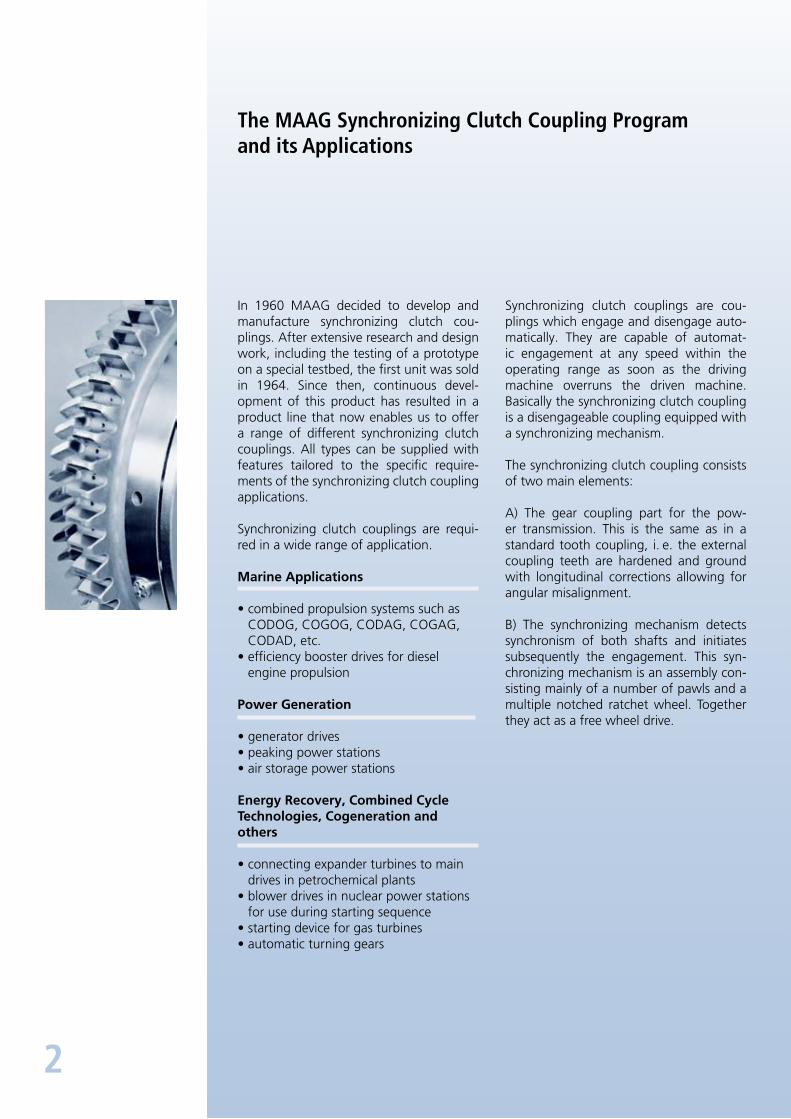
Synchronizing clutch couplings are couplings which engage and disengage automatically. They are capable of automatic engagement at any speed within the operating range as soon as the driving machine overruns the driven machine. Basically the synchronizing clutch coupling is a disengageable coupling equipped with a synchronizing mechanism.
The synchronizing clutch coupling consists of two main elements:
A) The gear coupling part for the power transmission. This is the same as in a standard tooth coupling, i. e. the external coupling teeth are hardened and ground with longitudinal corrections allowing for angular misalignment.
B) The synchronizing mechanism detects synchronism of both shafts and initiates subsequently the engagement. This synchronizing mechanism is an assembly consisting mainly of a number of pawls and a multiple notched ratchet wheel. Together they act as a free wheel drive.
2
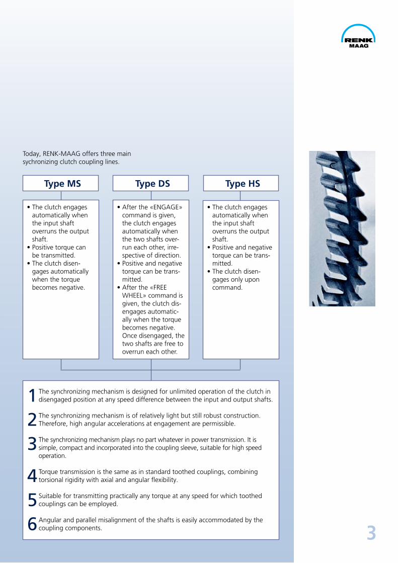
Today, RENKMAAG offers three mainsychronizing clutch coupling lines.
3
Type MS Type DS Type HS
1 The synchronizing mechanism is designed for unlimited operation of the clutch in disengaged position at any speed difference between the input and output shafts.
2 The synchronizing mechanism is of relatively light but still robust construction. Therefore, high angular accelerations at engagement are permissible.
3 The synchronizing mechanism plays no part whatever in power transmission. It issimple, compact and incorporated into the coupling sleeve, suitable for high speed operation.
4 Torque transmission is the same as in standard toothed couplings, combining torsional rigidity with axial and angular flexibility.
5 Suitable for transmitting practically any torque at any speed for which toothed couplings can be employed.
6 Angular and parallel misalignment of the shafts is easily accommodated by the coupling components.
• The clutch engages automatically when the input shaft overruns the output shaft.
• Positive torque can be transmitted.
• The clutch disengages automatically when the torque becomes negative.
• After the «ENGAGE» command is given, the clutch engages automatically when the two shafts overrun each other, irrespective of direction.
• Positive and negative torque can be transmitted.
• After the «FREE WHEEL» command is given, the clutch disengages automatically when the torque becomes negative. Once disengaged, the two shafts are free to overrun each other.
• The clutch engages automatically when the input shaft overruns the output shaft.
• Positive and negative torque can be transmitted.
• The clutch disengages only upon command.
4
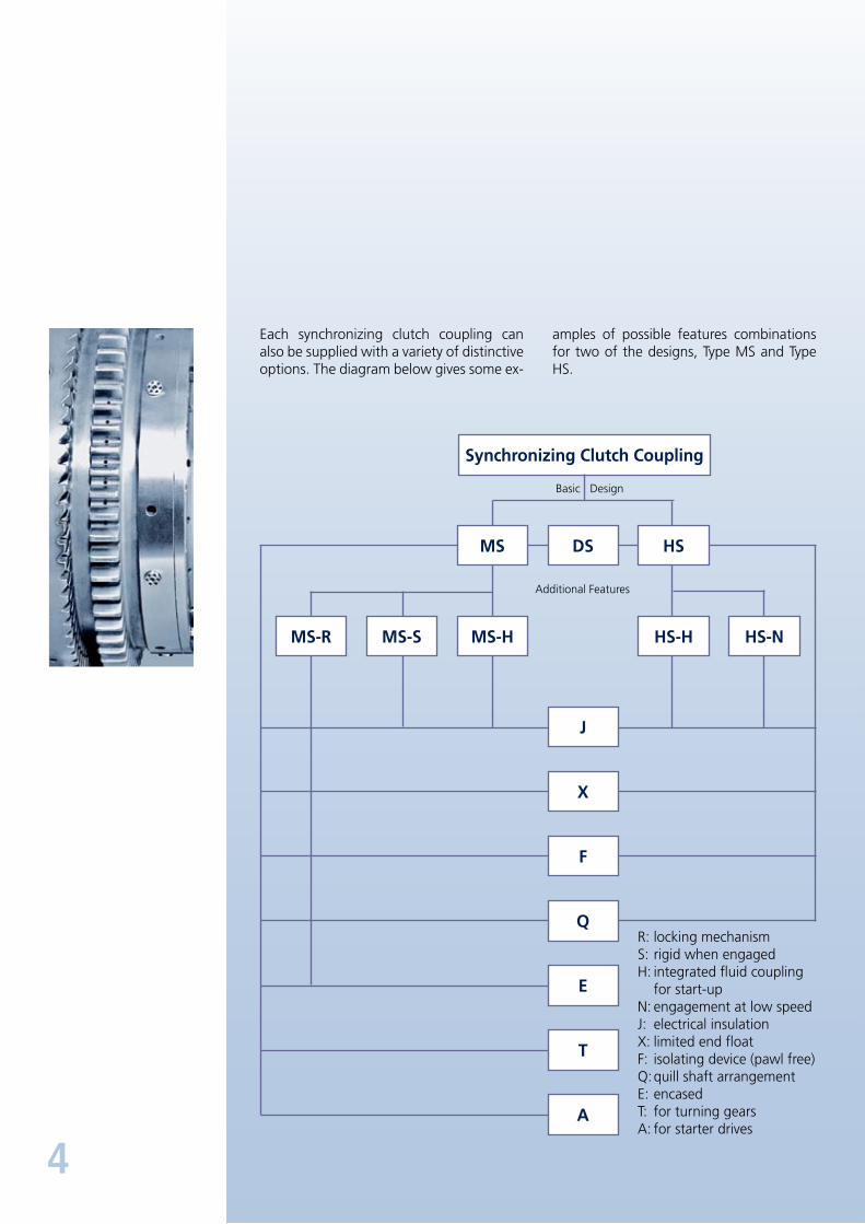
Each synchronizing clutch coupling can also be supplied with a variety of distinctive options. The diagram below gives some ex
amples of possible features combinations for two of the designs, Type MS and Type HS.
DS
Synchronizing Clutch Coupling
J
X
F
Q
E
A
T
MS-R MS-S
MS
MS-H HS-H
HS
HS-N
Basic Design
Additional Features
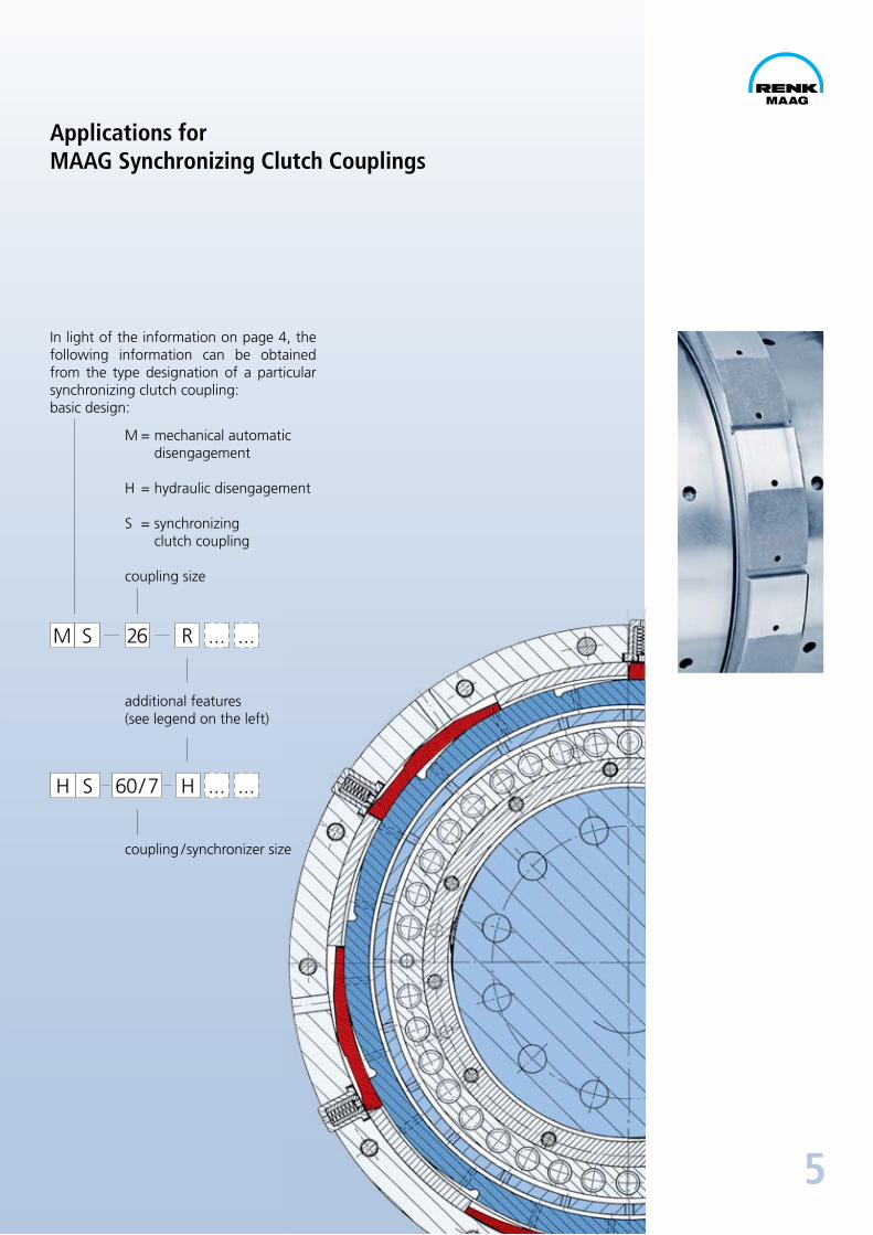
R: locking mechanismS: rigid when engagedH: integrated fluid coupling
for startupN: engagement at low speedJ: electrical insulationX: limited end floatF: isolating device (pawl free)Q: quill shaft arrangementE: encasedT: for turning gearsA: for starter drives
5
Applications forMAAG Synchronizing Clutch Couplings
In light of the information on page 4, the following information can be ob tained from the type designation of a particular synchronizing clutch coupling:basic design:
M = mechanical automatic disengagement
H = hydraulic disengagement
S = synchronizing clutch coupling
coupling size
M
H
S
S
26
60 / 7
R
H
additional features(see legend on the left)
coupling / synchronizer size
...
...
...
...

6
Marine Applications
Installation of a MAAG synchronizing clutch coupling type HS40F in a MAAG marine gearbox type DTA260W CODOG.
The synchronizing clutch coupling is mounted between the gas turbine and the first reduction pinion shaft, whereas the diesel engine is connected to the gearbox through a friction clutch.
At cruising speed, the diesel engine is clutched to the gearbox and the gas turbine is stationary with the synchronizing clutch coupling disengaged. If maximum speed is demanded the gas turbine will be started and accelerated. When the turbine shaft overruns the primary pinion, the clutch engages. The ship’s propulsion power is now delivered by the gas turbine, the
diesel engine is disconnected and the gas turbine accelerates further up to full speed.
When changing back to cruising speed, the gas turbine will be decelerated, the diesel engine started and clutched to the gearbox as soon as the speed is within the operating range of the diesel engine. After the load has been transferred from the gas turbine to the diesel engine, the disengage signal is given to the synchronizing clutch coupling, the clutch disengages and the gas turbine, disconnected from the main gear, runs down to standstill.
Synchronizingclutch couplingtype HS40F
Clutch coupling
Output (pinion shaft) Input (gas turbine)
Isolating device (manually operated)
Gearbox
Dieselengine
Friction clutch
Gas turbine
7
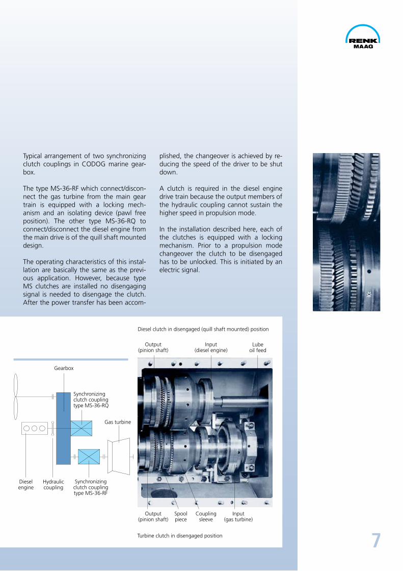
Typical arrangement of two synchronizing clutch couplings in CODOG marine gearbox.
The type MS36RF which connect/disconnect the gas turbine from the main gear train is equipped with a locking mechanism and an isolating device (pawl free posi tion). The other type MS36RQ to connect/disconnect the diesel engine from the main drive is of the quill shaft mounted design.
The operating characteristics of this installation are basically the same as the previous application. However, because type MS clutches are installed no disengaging signal is needed to disengage the clutch. After the power transfer has been accom
plished, the changeover is achieved by reducing the speed of the driver to be shut down.
A clutch is required in the diesel engine drive train because the output members of the hydraulic coupling cannot sustain the higher speed in propulsion mode.
In the installation described here, each of the clutches is equipped with a locking mech anism. Prior to a propulsion mode changeover the clutch to be disengaged has to be unlocked. This is initiated by an electric signal.
Synchronizingclutch couplingtype MS36RF
Dieselengine
Hydrauliccoupling
Diesel clutch in disengaged (quill shaft mounted) position
Turbine clutch in disengaged position
Output(pinion shaft)
Output(pinion shaft)
Spoolpiece
Couplingsleeve
Input(gas turbine)
Input(diesel engine)
Lubeoil feed
Gearbox
Gas turbine
Synchronizingclutch couplingtype MS36RQ
8
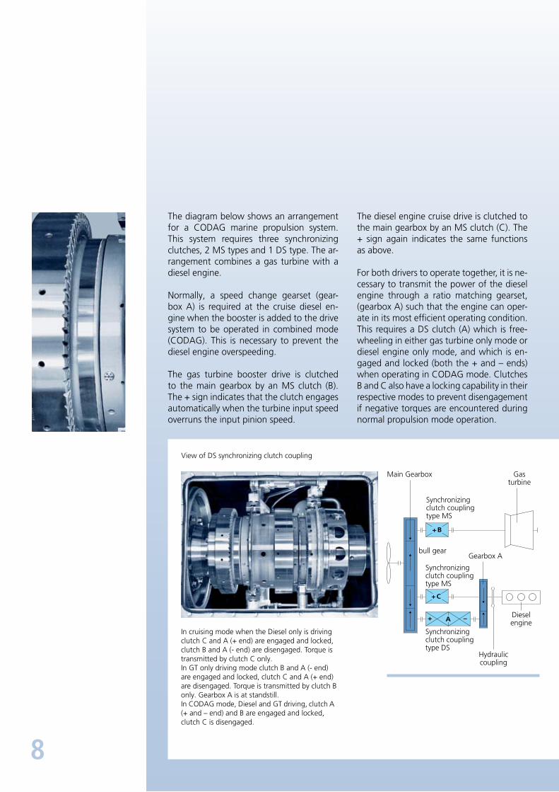
The diagram below shows an arrangement for a CODAG marine propulsion system. This system requires three synchronizing clutches, 2 MS types and 1 DS type. The arrangement combines a gas turbine with a diesel engine.
Normally, a speed change gearset (gearbox A) is required at the cruise diesel engine when the booster is added to the drive system to be operated in combined mode (CODAG). This is necessary to prevent the diesel engine overspeeding.
The gas turbine booster drive is clutched to the main gearbox by an MS clutch (B). The + sign indicates that the clutch engages automatically when the turbine input speed overruns the input pinion speed.
The diesel engine cruise drive is clutched to the main gearbox by an MS clutch (C). The + sign again indicates the same functions as above.
For both drivers to operate together, it is necessary to transmit the power of the diesel engine through a ratio matching gearset, (gearbox A) such that the engine can operate in its most efficient operating condition. This requires a DS clutch (A) which is freewheeling in either gas turbine only mode or diesel engine only mode, and which is engaged and locked (both the + and – ends) when operating in CODAG mode. Clutches B and C also have a locking capability in their respective modes to prevent disengage ment if negative torques are encountered during normal propulsion mode operation.
View of DS synchronizing clutch coupling
In cruising mode when the Diesel only is driving clutch C and A (+ end) are engaged and locked, clutch B and A ( end) are disengaged. Torque is transmitted by clutch C only.In GT only driving mode clutch B and A ( end) are engaged and locked, clutch C and A (+ end) are disengaged. Torque is transmitted by clutch B only. Gearbox A is at standstill.In CODAG mode, Diesel and GT driving, clutch A (+ and – end) and B are engaged and locked, clutch C is disengaged.
Main Gearbox
Gearbox Abull gear
Synchronizingclutch couplingtype MS
Synchronizingclutch couplingtype MS
Synchronizingclutch couplingtype DS
Gasturbine
Dieselengine
Hydrauliccoupling
9
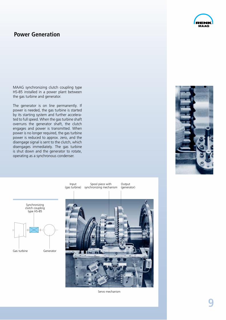
MAAG synchronizing clutch coupling type HS85 installed in a power plant between the gas turbine and generator.
The generator is on line permanently. If pow er is needed, the gas turbine is started by its starting system and further accelerated to full speed. When the gas turbine shaft overruns the generator shaft, the clutch engages and power is transmitted. When pow er is no longer required, the gas turbine power is reduced to approx. zero, and the disengage signal is sent to the clutch, which disengages immediately. The gas turbine is shut down and the generator to rotate, operating as a synchronous condenser.
Power Generation
Synchronizingclutch coupling
type HS85
Gas turbine Generator
Input(gas turbine)
Spool piece withsynchronizing mechanism
Servo mechanism
Output(generator)
10
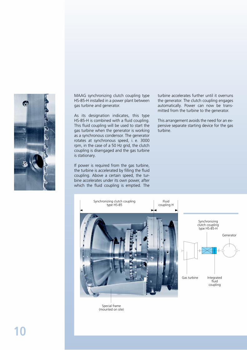
MAAG synchronizing clutch coupling type HS85H installed in a power plant between gas turbine and generator.
As its designation indicates, this type HS85H is combined with a fluid coupling. This fluid coupling will be used to start the gas turbine when the generator is working as a synchronous condensor. The gener ator rotates at synchronous speed, i. e. 3000 rpm, in the case of a 50 Hz grid, the clutch coupling is disengaged and the gas turbine is stationary.
If power is required from the gas turbine, the turbine is accelerated by filling the fluid coupling. Above a certain speed, the turbine accelerates under its own power, after which the fluid coupling is emptied. The
turbine accelerates further until it overruns the generator. The clutch coupling engages automatically. Power can now be transmitted from the turbine to the generator.
This arrangement avoids the need for an expensive separate starting device for the gas turbine.
Gas turbine Integratedfluid
coupling
Generator
Synchronizing clutch couplingtype HS85
Fluidcoupling H
Special frame(mounted on site)
Synchronizingclutch couplingtype HS85H

11
This is an example of a synchronizing clutch application in an air storage power plant.
The synchronizing clutch coupling type MS85S is mounted between the gas turbine (power turbine only) and the generator. In this case the MStype coupling has the Sfeature which means that the cou pling will behave like a rigid coupling when engaged.
Disgengageablecoupling
Output(generator/motor)
Input(gas turbine)
Synchronizingclutch couplingtype MS85S
Exploded view of the typeMS85S synchronizing clutch coupling
Centrifugalcompressor
Generator/motor
Gas Turbine(power turbine
only)
12
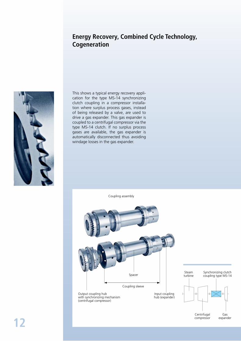
Energy Recovery, Combined Cycle Technology, Cogeneration
This shows a typical energy recovery application for the type MS14 synchronizing clutch coupling in a compressor installation where surplus process gases, instead of being released by a valve, are used to drive a gas expander. This gas expander is cou pled to a centrifugal compressor via the type MS14 clutch. If no surplus process gases are available, the gas expander is automatically disconnected thus avoiding windage losses in the gas expander.
Steamturbine
Synchronizing clutchcoupling type MS14
Centrifugalcompressor
Gasexpander
Output coupling hubwith synchronizing mechanism(centrifugal compressor)
Input couplinghub (expander)
Coupling sleeve
Spacer
Coupling assembly
13
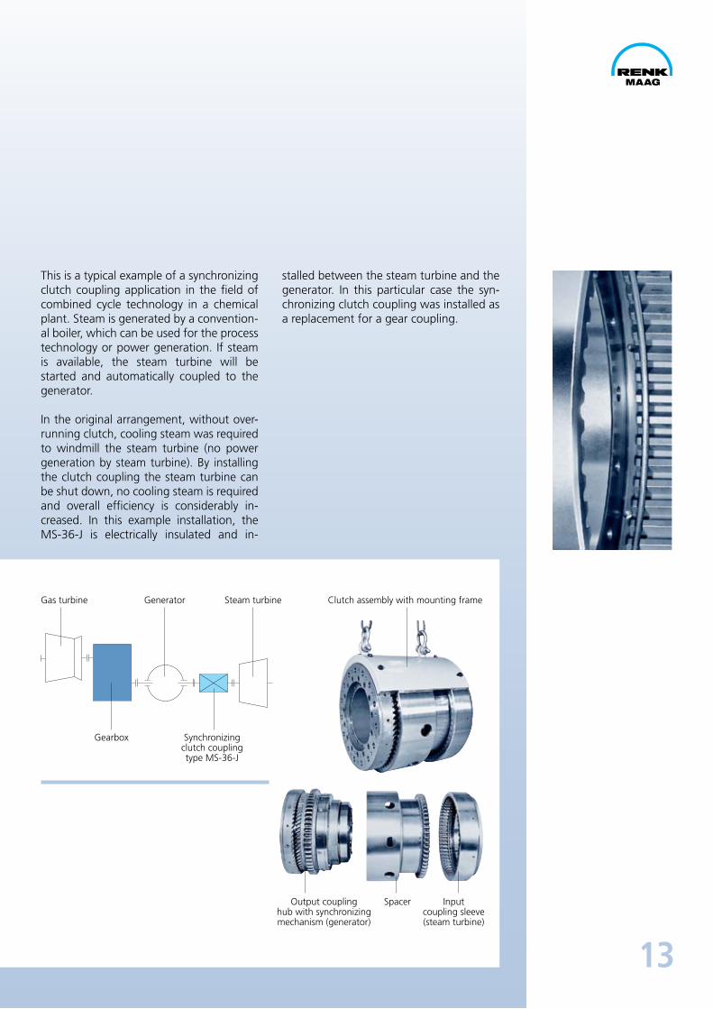
This is a typical example of a synchronizing clutch coupling application in the field of combined cycle technology in a chemical plant. Steam is generated by a conventional boiler, which can be used for the process technology or power generation. If steam is available, the steam turbine will be started and automatically coupled to the generator.
In the original arrangement, without overrunning clutch, cooling steam was required to windmill the steam turbine (no power generation by steam turbine). By installing the clutch coupling the steam turbine can be shut down, no cooling steam is re quired and overall efficiency is considerably increased. In this example installation, the MS36J is electrically insulated and in
stalled between the steam turbine and the gener ator. In this particular case the synchronizing clutch coupling was installed as a replacement for a gear coupling.
Output couplinghub with synchronizingmechanism (generator)
Inputcoupling sleeve(steam turbine)
Spacer
Clutch assembly with mounting frameGas turbine Generator Steam turbine
Synchronizingclutch couplingtype MS36J
Gearbox
14
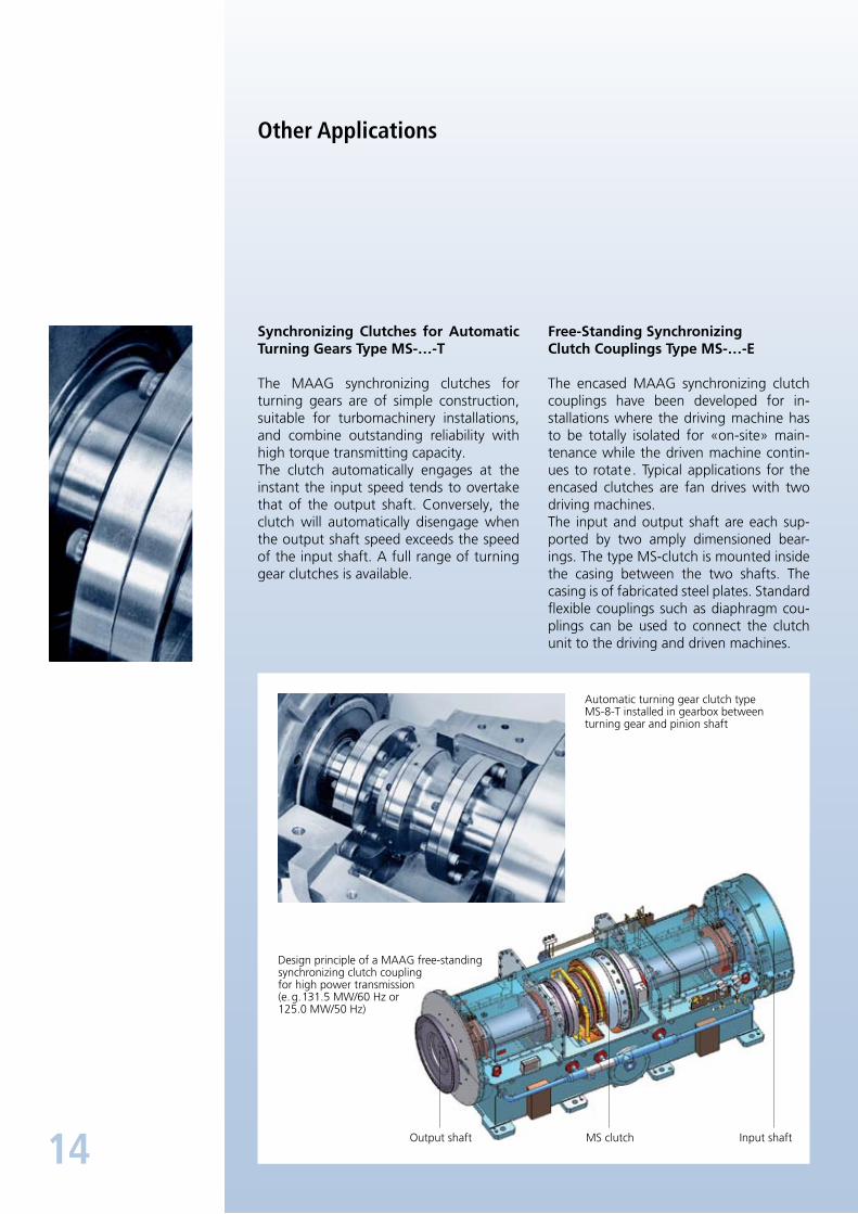
Other Applications
Synchronizing Clutches for Automatic Turning Gears Type MS-…-T
The MAAG synchronizing clutches for turn ing gears are of simple construction, suit able for turbomachinery installations, and combine outstanding reliability with high torque transmitting capacity.The clutch automatically engages at the instant the input speed tends to overtake that of the output shaft. Conversely, the clutch will automatically disengage when the output shaft speed exceeds the speed of the input shaft. A full range of turning gear clutches is available.
Free-Standing SynchronizingClutch Couplings Type MS-…-E
The encased MAAG synchronizing clutch couplings have been developed for installations where the driving machine has to be totally isolated for «onsite» maintenance while the driven machine continues to rotate. Typical applications for the encased clutches are fan drives with two driving machines.The input and output shaft are each supported by two amply dimensioned bearings. The type MSclutch is mounted inside the casing between the two shafts. The cas ing is of fabricated steel plates. Standard fle xible couplings such as diaphragm couplings can be used to connect the clutch unit to the driving and driven machines.
Input shaftMS clutchOutput shaft
Automatic turning gear clutch type MS8T installed in gearbox between turning gear and pinion shaft
Design principle of a MAAG freestanding synchronizing clutch couplingfor high power transmission(e. g. 131.5 MW/60 Hz or125.0 MW/50 Hz)
15
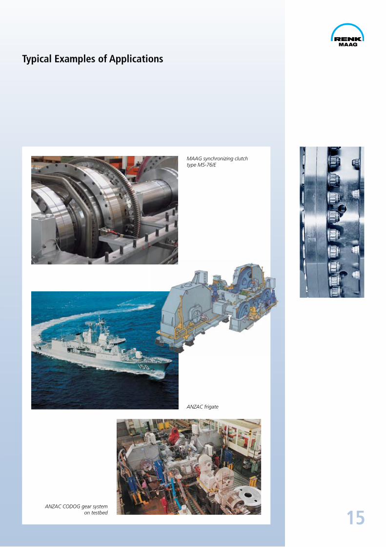
Typical Examples of Applications
MAAG synchronizing clutchtype MS-76/E
ANZAC frigate
ANZAC CODOG gear systemon testbed

RENK-MAAG GmbHPostfach 3068 • Sulzer-Allee 46 • CH-8404 WinterthurTel. +41 (0) 52 262 89 88 • Fax +41 (0) 52 262 89 89
[email protected] • www.renk-maag.ch
Neu
aufl
age
Kü
09.
2010
e
Customer Service / Spare Parts / Maintenance / Testbed
RENK-MAAG cares for the customer during and after the sales: Our ef-ficient sales team is prepared to give advice regarding new equipment and original spare parts for cou-plings and gearboxes of MAAG type. On-site support is provided world-wide for all MAAG-turbo and marine gearboxes by our experienced and certified field service engineers. Pe-riodical and/or preventive mainte-nance assure the safe and reliable operation of equipment. Our service field engineers are at your disposal for inspections and maintenance.
In case of need to fully refurbish or revamp a gearbox, coupling or com-ponents at our facility, we provide a full range of support with the deliv-ery of a re-warranted unit.
New gearboxes and components can thoroughly be tested applying the latest technology in diagnostic mon itoring equipment for vibration, temperature and sound.
Test runs of refurbished gearboxes are also concluded where verifica-tion of repair work must be certified.
RENK-MAAGis at your disposal
Production and other activities are monitored by the internal quality
assurance system and in strictcompliance with ISO 9001 : 2008.