report on concurrent engineering implementation …concurrent engineering (ce) is a systematic...
TRANSCRIPT

REPORT
ON
CONCURRENT ENGINEERING
IMPLEMENTATION IN A SHIPYARD
A Project ofThe National Shipbuilding Research Program
for
The Society of Naval Architects and Marine EngineersShip Production Committee
Industrial Engineering Panel (SP-8)
Prepared By
Bath Iron Works Corporation700 Washington Street
Bath, Maine

Report Documentation Page Form ApprovedOMB No. 0704-0188
Public reporting burden for the collection of information is estimated to average 1 hour per response, including the time for reviewing instructions, searching existing data sources, gathering andmaintaining the data needed, and completing and reviewing the collection of information. Send comments regarding this burden estimate or any other aspect of this collection of information,including suggestions for reducing this burden, to Washington Headquarters Services, Directorate for Information Operations and Reports, 1215 Jefferson Davis Highway, Suite 1204, ArlingtonVA 22202-4302. Respondents should be aware that notwithstanding any other provision of law, no person shall be subject to a penalty for failing to comply with a collection of information if itdoes not display a currently valid OMB control number.
1. REPORT DATE NOV 1995
2. REPORT TYPE N/A
3. DATES COVERED -
4. TITLE AND SUBTITLE Report on Concurrent Engineering Implementation in a Shipyard
5a. CONTRACT NUMBER
5b. GRANT NUMBER
5c. PROGRAM ELEMENT NUMBER
6. AUTHOR(S) 5d. PROJECT NUMBER
5e. TASK NUMBER
5f. WORK UNIT NUMBER
7. PERFORMING ORGANIZATION NAME(S) AND ADDRESS(ES) Naval Surface Warfare Center CD Code 2230-Design Integration ToolsBldg 192, Room 128 9500 MacArthur Blvd, Bethesda, MD 20817-5700
8. PERFORMING ORGANIZATIONREPORT NUMBER
9. SPONSORING/MONITORING AGENCY NAME(S) AND ADDRESS(ES) 10. SPONSOR/MONITOR’S ACRONYM(S)
11. SPONSOR/MONITOR’S REPORT NUMBER(S)
12. DISTRIBUTION/AVAILABILITY STATEMENT Approved for public release, distribution unlimited
13. SUPPLEMENTARY NOTES
14. ABSTRACT
15. SUBJECT TERMS
16. SECURITY CLASSIFICATION OF: 17. LIMITATION OF ABSTRACT
SAR
18. NUMBEROF PAGES
130
19a. NAME OFRESPONSIBLE PERSON
a. REPORT unclassified
b. ABSTRACT unclassified
c. THIS PAGE unclassified
Standard Form 298 (Rev. 8-98) Prescribed by ANSI Std Z39-18
Executive Summary
Concurrent Engineering (CE), a systematic approach to involving all affected functions in thesimultaneous development of products and processes, has received wide recognition as a means ofsignificantly improving overall operating results for manufacturing companies. When successfullyapplied, the CE process results in significant improvements in customer satisfaction, quality and cycletime. DOD studies and industry experience show that CE may reduce the number of design changes by50%, reduce design to production time by 40-70%, and decrease scrap and rework by 75%.
In the belief that the benefits of CE methodologies could assist the U.S. shipbuilding industry to becomeinternationally competitive, the NSRP awarded a contract to BIW, supported by a consultant team headedby Thomas Lamb, to study the application and implementation of CE to the U.S. shipbuilding industry.The study was awarded in July 1993 and completed in July 1995. Previous reports have described theApplication Phase of the study and provided a User’s Guide and Primer in Concurrent Engineering. Thisfinal report describes a pilot CE implementation conducted at BIW from December 1993 through June1995 and an industry-wide Workshop held in Portland Maine in June 1995.
The CE pilot implementation began with the evaluation and selection of a host design/construction projectin December 1993. After balancing the need for manageable size, project significance and schedulecompatibility, the ARPA funded MARITECH Commercial Shipbuilding Focused Development Projectinvolving the development of two vehicle carrier designs, was selected. Other major elements of thisproject included technology transfer from European and Japanese shipyards, facilities design, buildstrategy development and contracts/financial planning. A significant advantage of this project withrespect to CE was the involvement of two major US ship owner/operators.
The implementation effort was divided into several phases: team selection, team and managementtraining, design strategy, and design execution. Training, including the facilitation of the design strategydevelopment, was entrusted to Mr. Bart Huthwaite of Institute for Competitive Design (ICD). ICD’Sspecific CE methodology, including multi-disciplinary teaming, a business oriented design strategy,continuous process and product measurement etc. was used throughout the pilot implementation andproved to be adaptable to the ship design process.
The contract design of the first vehicle carrier was successfully completed in June 1995. BIW hascontinued to utilize CE on the second ship design of the Focused Development Project and hasimplemented elements of CE on several smaller design/construction projects. Although specific costcomparisons are difficult to obtain Waler practical shipyard conditions, the ability to rapidly iterate thedesign cycle, including parallel development of production, facility, and material plan, and cost estimates,is clearly a powerful force for cost reduction. With further refinement, CE will effectively support the USshipbuilding industry’s drive to regain international competitiveness.
An industry-wide Workshop to disseminate the results of this NSRP project coordinated by ThomasLamb, was attended by some 60 people from US and Canadian shipyards, equipment suppliers andacademia. The program included speakers from industries in which CE has been successfully employed,team exercises in CE application, and a full report on the pilot implementation by the BIW employeesdirectly involved. Feedback from the participants indicates that this material was well received and willassist them in establishing their own CE programs.
- i -

Acknowledgment
This project was funded by the National Shipbuilding Research Program Industrial Engineering Panel(SP-8), chaired by R. A. Wallen of Newport News Shipbuilding. The SP-8 Panel is one of the ShipProduction Committee Panels of the Society of Naval Architects and Marine Engineers, which wasestablished for the purpose of improving U.S. shipbuilding peformance.
Portions of this report are adapted from a paper presented by James G. Bennett and Thomas Lamb at the1995 Ship Production Symposium.
The success of the pilot CE implementation was accomplished through the efforts of many BIWmanagers and staff,’ as well as the full cooperation of the client ship owner, ABS, major suppliers andmany others. Their participation and assistance is acknowledged with appreciation.
- i i -
Mr. Bart Huthwaite of the Institute for Competitive Design provided inspiration, training andmethodology without which the pilot implementation phase could not have succeeded. His support isgreatly appreciated.

Executive Summary
Acknowledgment
1.0 Introduction
TABLE OF CONTENTS
PAGE
2.0 Implementation of CE at Bath Iron Works Corp.
2.12.22.32.42.52.62.72.82.8.12.8.22.8.32.8.42.8.52.8.62.8.72.8.82.8.92.9
Selection of a Pilot ProjectMARITECH Focused Development ProjectImplementation PlanTeam OrganizationCE TrainingManagement TrainingProduct Delivery StrategyProduct Development Team TrainingAnalysis of Competitive EnvironmentStrategic DesignInnovationProduct and Process Measurement SkillsTeam Organization and Decision MakingAccountabilityCommunicationsInterpersonal Skills Tools and Enabling TechnologiesResults and Conclusions
3.0 References
Appendix A: CE Workshop - Implementation
i
ii
1
2
22355667789
10111112121313
14
-111-

1.0 Introduction
Concurrent Engineering (CE) is a systematic approach to the simultaneous development of products andprocesses, involving the areas of design, manufacturing, materials, contracts, marketing, subcontractors,customers, regulators and others. It is based on removing the cultural and organizational barriers thathistorically have prevented these functions from working together. The CE process ensures that peoplereach timely, coordinated, well informed decisions concerning all critical elements of product design,manufacturing and life-cycle costs.
Concurrent Engineering has received wide recognition as a means of significantly improving overalloperating results for manufacturing companies. When successfully applied, the CE process results insignificant improvements in customer satisfaction, quality and cycle time. DOD studies and industryexperience show that CE may reduce the number of design changes by 50%, reduce design to productiontime by 40-70%, and decrease scrap and rework by 75%.
In the belief that the benefits of CE methodologies could assist the U.S. shipbuilding industry to becomeinternationally competitive, the NSRP awarded a contract to BIW, supported by a consultant team headedby Thomas Lamb, to study the application and implementation of CE to the U.S. shipbuilding industry.The objectives of the study were
1.
2.
3.
4.
To determine the extent of current applications of CE in shipyards, their familiarity with it andthe potential benefits from its application,
To show how CE reduces time to design and manufacture a product while improving qualityand reducing cost,
To produce a guide for CE application to the U.S. shipbuilding industry as a first step to actualimplementation,
To implement CE on a specific shipyard design and construction program.
This study ran from August 1993 through July 1995 and resulted in several reports as well as an industry-wide workshop. Work by Thomas Lamb and his team generated two reports on the Application phase ofthe study, covering objectives 1-3 above: an applications report (ref (a)) and industry primer (ref (b)). Apaper by J.G. Bennett of BIW and Thomas Lamb was presented at the 1995 Ship Production Symposium,covering both application and the early stages of an implementation pilot project at BIW (ref (c)). In June1995, a CE Workshop was held in Portland, Maine at which the application study was reviewed and theresults of this pilot implementation were described.
- 1 -

2.0 Implementation of CE at Bath Iron Works Corp.
As with most shipyards, elements of CE have been part of the evolving product development process atBIW for a number of years. In particular, past focus has been on involvement of shipyard planning andproduction engineering fimctions in the design process, overlapping design and production phases ofproduct development, application of enabling technologies such as CAE/CAD/CAM, and more recentlythe use of teams in management of the product delivery process. In addition to the CE pilot described inthis paper, a number of other ongoing projects at BIW have implemented best practices identified throughCE bench-marking and technology transfer with industry leaders. The CE pilot described hereinrepresents an intensifiled and focused effort to implement all of the essential elements of CE within asingle project, and to thereby lay the foundation for broadened understanding and institutionalization ofthese practices throughout all future product development efforts.
2.1 Selection of a Pilot Project
The CE Pilot implementation began with the evaluation and selection of a pilot project in December,1993. Numerous candidate projects were ongoing or proposed including barge mounted electrical powergenerating plants, lubricating oil purification modules for shore-based electric plants, a small coastalcombatant ship, a MARITECH funded multiple ship design project and a major upgrade to the DDG 51class destroyers presently under contract.
These projects were evaluated on the basis of several criteria including project size, manageability,required level of effort breadth of scope, duration, significance in relationship to other shipyard projectsand affordability. The project had to be small enough to be manageable, i.e., the size of the effort had tobe such that if obstacles were encountered there would be some flexibility in managing the impact onresources and other projects in the shipyard. A significant emphasis was placed on the need for shipyardcontrol of the design and product delivery process. It was recognized that if external constraints were toorigid, either in terms of product specifications or contractual requirements, that the potential benefit of theproject would be compromised. Counter-balancing the need for manageable size was the need to have thescope and nature of the project recognizable as a significant undertaking in terms of complexity, technicalchallenge and importance to the shipyard. It was desirable that the duration of the project be relativelyshort in order to produce measurable and identifiable results. The overriding constraint in all cases wasthat potential projects had to be funded and approved by senior management.
As expected, none of the candicdate projects met all of the above criteria. The most difilcult criteria tobalance was the need for significance versus the desire for short durtion. Of the significant shipbuildingprojects considered, all were expected to span more than a years time, due to the basic nature of largeshipbuilding projects - size, complexity and level of effort - and the fact that contracts with specificcommercial customers had yet to be developed.
A meeting was held in December, 1993, at which BIW managers met along with the NSRP Applicationsteam to decide which of the candidate projects would become the CE pilot. As this meeting, it wasdecided that the recently awarded MARITECH design project offered the best prospects for successfulimplementation. Factors which favor the selection of this project include: it is recognized as significantwork for the shipyard, external constraints are manageable, risk to other ongoing projects is minimal,scope is broad involving all phases of ship design and construction, and funding had been obtained.
A key issue on which a compromise had to be reached was the probable duration and scheduled start ofactual CE implementation relative to the desires of the NSRP. It had initially been desired that the pilotbe complete within one year from the start of the NSRP project. In the case of the selected CE Pilot, theduration of the project wouId necessarily be prolonged due to the relationship between it and the largerMARITECH “focused development project” through which it is funded. The MARITECH focuseddevelopment project involves not only the development of multiple ship designs but also development of
- 2 -

2.1 Selection of a Pilot Project (continued)
facilities modernization plans, commercial ship financing plans and technology transfer between BIW andtwo foreign shipyards, Kvaerner Masa Yards (KMY) and Mitsui Engineering and Shipbuilding (MES).As such, the implementation plan, schedule and duration of the CE pilot had had to adjust to fit within thefiamework of these other activities.
2.2 MARITECH Focused Development Project
The objective of the MARITECH focused development project at BIW is to achieve re-entry into thecommercial shipbuilding market.. The last commercial ships built at BIW were delivered in 1983.Product development efforts since that time have focused almost exclusively on military combatants forthe U.S. Navy. As previously alluded, the MARITECH project focuses on developing essentialcapabilities in all areas of the ship design and production process necessary to re-enter the commercialmarket. These areas include: design, construction facilities, human resources, contracts and financing.
The firt step in this effort has been the definition of specific capabilities and technologies required ineach of these areas. ‘This has been approached by conducting in-depth studies of two world leadingshipbuilders, Kvaerner Masa Yards (KMY) and Mitsui Engineering and Shipbuilding (MES). Severalteams of individuals representing all functional areas of the company were involved in bench-marking ofthese two companies. A total of 45 BIW employees were involved in these exercises. The red is a verybroad and thorough understanding of the work methods, procedures, technical and administrative systemsmanagement practices and productivity at all levels of these two world-class shipbuilders.
The knowledge gained through these bench-marking exercises is being applied through a team effortcoordinated by a Commercial Shipbuilding project group comprised of representatives from all functionalareas of the Company. Members of this team, co-located within the shipyard, are responsible fordeveloping ship designs, shipyard facilities plans, ship construction plans, marketing plans, contract andfinancing arrangements, human resource and training plans.
Obviously, ship designs and construction plans have rio use if they do not serve a viable market withknown prospective customers. One of the principals of CE is to involve the customer directl in thedevelopment of new product design: and delivery strategies. in the case of the MAITECH project, twoprospective customers were identified at the outset. Both are ship operators that presently own andoperate ships in the commercial vehicle transport trade. Both were approached and agreed to cooperatewith BIW in developing the initial MARITECH project proposal and to participate as partners in thesubsequent product development effort. The direct participation of the senior management, technical andoperations staff of these potential customers in the CE process has been essential to achieving the goal ofdirect and ongoing customer interface throughout the product development process. In addition,marketing surveys and participation in important industry conferences and technical symposia are alsomeans that are being used to achieve this goal of the CE effort.
2.3 Implementation Plan
The CE Pilot effort is broken down into several principal phases: Team Selection, Team Training,Management Training, Product Delivery Strategy, first (of two) Ship Designs (Figure 2.3 a). Ongoingand in parallel with this activity is the technology transfer between KMY and Mitsui previouslydescribed. The ships being designed are RORO vehicle carriers. Each design has unique requirements in
- 3 -

2.3 Implementation Plan (continued)
terms of required cargo capacity, handling and stowage capabilities, deadweight tonnage, service speedand limiting drafts.
This process culminated with the completion of the first ship design in May 1995, followed by acomprehensive construction cost estimate update in early August. The process was carried out in parallelwith technology transfer activities at both KMY and Mitsuii. The same team will go on to develop thepreliminary design of a second vehicle carrier later this year.
FIGURE 2.3 a
- 4 -

2.4 Team Organization
As discussed earlier, there is as yet no established organizational model from within the shipbuildingindustry to follow in determining the composition of a shipyard CE team. Reported U.S. shipyard CEexperience has focused primarily on “enabling technology” - CAD product models, distributed databases,document and work flow management systems - as opposed to CE team organization. This is also truewith respect to foreign shipyards which have for the most part not adopted a formal CE approach in theirproduct development processes, at least insofar as establishing CE team organizations distinct from theline organization.
The team was organized within the Commercial Shipbuilding Project Office (CSPO), a projectorganization reporting to VP Marketing. The overall team structure evolved into three entities:
The Product Development Team (PDT) functions included representatives from all affectedfunctions as listed below. The majority of PDT members received the training described belowand participated in the development of the design strategy. During the design process the PDTparticipated in trade-off studies and reviewed design products to ensure that the design wascompatible with facilities, production processes, material availability and owner requirements.Except for those who were also part of the Core Team, PDT members remained attached to theirline organization departments.
Production Facilities Outfit Detail DesignFacilities Engineering Structural Production Material Procurement Outfit ProductionEstimating Ship OwnersStructural Detail Design Design Subcontractor
The Core (design) Team consisted of five engineers covering the disciplines listed below, who wereresponsible for the pre-contract design of the ship. These individuals were detached from their linefunctions and reported to a manager within the CSPO.
Naval Architecture Mechanical EngineeringStructural Engineering Electrical Engineering
Finally, the Support Team consisted of all those within the line organization who were called on foradditional support by any of the above. Members of the Core Team or PDT assumed custodialresponsibility for representing, interacting with and directing support team activities. Example disciplinesincluded
Hydrodynamics Mechanical DesignStructural Design Weight EstimatingOutfit Design Marketing
In addition to the team structures, a senior management sponsor and advisory council was designated toprovide oversight accountability and direction to the team.
2.5 CE Training
Training of the CE team is an essential element of implementation. In BIW’S case, considerable efforthad been made over the past several years to provide broad-based training in team problem solvingtechniques. In-house training programs include one to three day courses providing instruction in teamprocess orientation, management leadership and specific matters relating to the ongoing transition fromtrade to muhi-disciplinary work teams in production. This training can provide useful background for
- 5 -
2.5 CE Training (continued)
participants in a CE process, however, it provides only one of several skill sets that are essential to acompetitive product development team. beyond basic technical design and team problem solving skills,development of skills in the following areas is considered to be essential:
• Analysis of Competitive Environment• Strategic Design• Innovation● Process and Product Measurement• Team Dynamics Measurement• Interpersonal Interacting
Extensive training material has been developed and is available from CERC and the Institute forCompetitive Design (ICD), Rochester, Michigan, to instruct product development teams in these areas.The ICD program has been applied in the training of product development teams at over 300 companiesworld-wide. As one of the NSRP project tasks, BIW agreed to apply the ICD method and to evaluate itseffectiveness in preparing the CE pilot team.
The agreed upon training program was planned during a visit by Mr. Bart Huthwaite of ICD to BIW inDecember 1993. It focused on three areas:
1.2.3.
Management trainingProduct development team training, and Facilitating development of a Vehicle Canier Product Delivery Strategy(the Strategic Design Brief).
2.6 Management Training
Management training began with the initial visit of Mr. Huthwaite to BIW in December 1993, in which heconducted a CE orientation briefing in conjunction with the bench-marking exercise previously described.This briefing covered the basic principals of CE and including an hour long questions and answer sessionin which many organizational and procedural issues were discussed. A second management trainingsession was held on March 8, 1994. This session included members of the pilot product developmentteam as well as Mr. Huthwaite. The product development team presented the results of the training
workshop, described later, in which they had participated. Another important element of this session wasan evaluation of management confidence level in the existing product development process. The intent ifthis exercise was to establish a baseline against which to measure the effectiveness of the CEimplementation effort. This evaluation included strategic perspective, speed, cost awareness, quality andefficiency of present produce development efforts. In each of these areas, four to five specific questionsrelating to performance of present product development efforts were asked. Managers rated corporateperformance on a simple scale of one to ten. The overall results indicated a less than satisfactoryperception of the existing product development process.
2.7 Product Delivery Strategy
The development of a “product delivery strategy” within the context of a CE process is very similar to theexercise of developing a “build strategy”. The actual process involved is described below as part of CE
- 6 -

.-
2.7 Product Delivery Strategy (continued)
product development team training. The result of this process is a 30-50 page document which spells outspecific product attributes, metrics, action plans and responsibilities for accomplishing the developmentof a new product. The development of this document took place over a period of four days, from August5-8,1994, in which members of the product development team including ship owner’s representatives andrepresentatives from all internal BIW division participated. This process culminated in the presentationof the product delivery strategy to senior management.Specific results of this effort will be presented at the industry-wide CE workshop planned for June, 1994,in Bath, Maine.
.
2.8 Product Development Team Training
Training of CE product development team, comprised of both core and support team members, wasconducted by Mr. Huthwaite from January 12-15 at BIW. Between 25 and 30 BIW employeesparticipated throughout a period of four days. The purpose of this effort was to provide thoroughunderstanding of the fundamental skills required of product development teams, and to provide hands onexperience in the application of these skills through a series of hands-on exercises. A second four-daysession was held to develop, and present to management a “Strategic Design Brief’ (Design Strategy) forthe vehicle earner designs. In general, the format for these sessions follows a set sequence that beginswith explanation of a particular technique by Mr. Huthwaite followed by discussion involving the entiregroup, break-up” of the group into working teams, application of technique to a sample problem,presentation of results by each team, and critique of results by the entire group. For the purposes oftraining the group was given the task of designing a simple mechanical device. Initially, the devicechosen was one used by Mr. Huthwaite with many training groups over a long period of time. Byexercising its skills in designing this simple device, the group was able to compare its results with theresults of many other groups facing the same challenge. The comparisons, needless to say, were quiteintriguing. The group also worked with a sample design problem representative of that which would beencountered in a typical ship design situation. The chosen example was a down-flooding device to beused in refrigerated cargo holds wherein the device would serve as an effective barrier against thepressure, temperature and humidity differences between two adjacent cargo holds as well as functionreliably as a cross connection in the case of flooding.
2.8.1 Analysis of Competitive Environment
For a produce development team to be effective, it must have a clear understanding of the competitiveenvironment in which it operates. This environment is characterized by
● Customer’s needs including:
- functional requirements;- price expectations;- performance expectations;- schedule demands.
● Current competitive products available under development in the marketplace.
- 7 -

2.8.1 Analysis of Competitive Environment (continued)
● External and internal constraints including:
- Available capital resources;- Available technology,- Safety and environmental regulations;- Other legal or political restrictions.
• Internal strengths and weaknesses including:
- Available skills and experience;- Shipyard tooling, facilities and capacity;- Proven capability in the marketplace.
By tasking the product development team to analyze the competitive environment, the entire team isdriven to define and focus attention on what are the most important problems to be solved in the designprocess. In general, it is more important at the outset that the team by working to solve the rightproblems, as opposed to working to immediately solve any particular problem right.
An effective strategy employed by the BIW CE pilot team is to observe the operations of ship typessimilar to that which is to be designed. Direct discussions with ship operating crews, port facilityoperators as well as ship owners are essential to understanding the competitive environment in which theship will operate. Comprehensive data regarding the port restrictions, usage fees, insurance fees,operating and maintenance costs, crew skill, qualifications and experience were being sought. Industrytrade journals and reports of pertinent regulatory agencies have been reviewed, compiled, analyzed andcondensed. A strategic goal of this effort was to consolidate a technical Iibrary of ship designs to serve asdesign performance benchmarks in the development of new ship designs.
To understand its own competitive strengths and weaknesses, it is necessary for a company to view itselffrom the outside looking in. Bench-marking of competitors is one way to gain this perspective.Considerable recent research and attention have been devoted to analyzing the general competitivestrengths and weaknesses of the U.S. shipbuilding industry. This work can serve as a useful starting pointin developing techniques for analyzing and quantifying its own specific strengths and weaknesses. Theuse of consultants to obtain a third party opinion may also be of benefit.
2.8.2 Strategic Design
The analysis of the competitive environmental provides a rational basis for defining specific functionalattributes of the product design. Traditionally, these attributes are described in an outline specificationdeveloped by the marketing department in conjunction with a potential customer. In a CE process, othershipyard departments are involved in this process through participation in the product development team.In the CE process, the definition of product fictional attributes is not limited to just external customerrequirements, but is expanded to include the requirements of internal “customers” as well. The result is aset of requirements that reflects the company’s strengths and capabilities and that ultimately leads toachievement of the highest quality within the competitive constraints of the market.
The process of defining product attributes in a team environment is quite straightforward. The teamdivides into groups, the groups compose lists of attributes, the attributes are categonzed evaluated againstthe company’s strengths, internal and external constraints, ranked in priority order and finally selected by
- 8 -

2.8.2 Strategic Design (continued)
.
the team to be either included or excluded. The objective of this effort identify the eight mostimportant competitive attributes of the product. These eight will become the basis for futuremeasurement of product success. One important criteria in the selection of these attributes is that eachattribute must be quantifiable in terms of some measurement of the product design, e.g., cargo deadweightcapacity or the number of structural parts are both measurable attributes of a ship design.
For each product attribute, three measurements or metrics are initially identified
1. The current design value;2. The minimum or threshold value considered to be acceptable, and3. The objective value or competitive goal.
(See Appendix A, pages 102- 104).
For a complex product such as a ship, the idea that there should be only eight attributes of the designconsidered “most important” created a great deal of controversy within the pilot product developmentteam. To resolve this controversy, the technique used was to broaden or categorize the definition of theeight most important competitive attributes, and to discretely specifiy attributes and associatedmeasurements within each broad category. Thus, a broad category such as maintainability could beidentified as a critical product attribute, but quantified in terms of several more discrete attributes such asoverhaul and dry-docking interval, underway maintenance tasks, crew size, number of required spares,etc.
The essential benefit of this exercise is that it focuses the team’s attention on the attributes which are mostimportant to the success of the product design, and provides quantifiable goals for the measurement of thedesign in process.
Another important outcome of this process is the definition of the “step”, “stretch” and “leap” versions ofa product representing the present version, the next incremental evolution and the future long term visionof a product. The product development team should be encouraged to look beyond present constraintsand/or limitations to envision how future versions of the product will evolve. In the marine industry, forexample, fiture requirements for safety, environmental protection, automation, etc. can be expected tohave significant impact on ship capabilities. The objective of developing a design strategy is not only toidentify and quantify competitive attributes of the present version of a product but to identifiy and plan forfuture development and improvement of the product. The ultimate goal is to provide for such
development and future upgrade of the product in the present design.
2.8.3 Innovation
The core technical skill of the product development team is its ability to innovate and develop costeffective technical, alternatives to achieving strategic design goals. In world-class product developmentteams, this is accomplished by iteration of multiple alternative designs and rational evaluation of thosedesigns based upon criteria that measure the total cost impact of their distinguishing attributes. It isessential that the product development team understand the total cost impact of alternative designs. Thisincludes understanding the principals of producible designs and developing the ability to map andevaluate the process impact of alternative design solutions. In the CE process, the core team effort isinitially focused on developing the technical solutions to the eight top priority competitive productattributes. In latter stages, support teams should also apply this methodology in developing detail designof subsystems and components.
- 9 -

2.8.3 Innovation (continued)
The principal elements of process based design include:
• Reducing numbers of parts.• Simplifying manufacturing processes.• Simplifying product structure/architecture.• Identi&ing and eliminating hidden costs.
Part number reductions can be achieved either through the greater use of “common” or “standard”components, by parts “implosion” or simply eliminating parts. Standardization is not a subject that isnew to the U.S. shipbuilding industry, however, by comparison the U.S. industry clearly has away to goin achieving the level of standardization typical of world leaders. One of the most successful strategiesemployed by industry leaders is the use of multi-functional materials, i.e., materials that can besubstituted or applied in a variety of situations. The use of high strength steel in lieu of mild steel for theequipment foundations to avoid having to stock two different grades is a good example. Parts implosionis the technique of creating a single part to accomplish the same function as previously accomplished by anumber of parts. The familiar case of using stanchions to both support grating and pipe running beneaththe grating is an example of part implosion. A simple example of parts elimination would be the use ofshallower deck stiffening which eliminates the needs for reinforcing collars in way of stiffenerpenetrations though web frames and bulkheads.
Process simplification is achieved in a number of ways including the elimination of process steps throughsimplification of the product design, and the reduction of variability and precision required in themanufacturing process. Examples of highly variable processes typically involved in shipbuilding includewelding, compound curvature in plate forming and compound bends in pipe bending. Designs that makeuse of modularity or repeatability will by definition have fewer process steps than otherwise. Design forassembly is also a technique for eliminating process steps in the assembly process. This is typicallyexploited in shipbuilding by designing for on-block and on-unit installation.
Simplification of product architecture means reducing the variety of technologies applies in production.This is the corollary to reducing the number of process steps. The objective is to simplify part geometry,eliminate sophisticated material forming and joining technologies, high precision/low tolerancemachinery, fitting, measuring and aligning. The use of poured chocks for instance is an example of asimplified product architecture for the mounting of a complex piece of equipment.
Eliminating hidden costs means identifying the various processes such as marshaling, staging, handling,tooling set-up, surface preparation and cleaning, testing, inspecting and documenting, required to enablethe production of a product. The evaluation of hidden cost is often the most difficult challenge facing theproduct development team. The involvement of production personnel in the product development processis essential to making well informed evaluation of the indirect costs incurred on the shop floor.
2.8.4 Product and Process Measurement Skills
The total cost associated with a given design is identified and understood by thoroughly examining theprocess steps involved in the production of that design. Many techniques have been devised to enablesuch analysis, including Quality Function Deployment, ICD/FOCUS methodology, Taguchi Methods,Boothroyd Dewhurst’s Product Design for Assembly, GE/Hitachi Assemblability Evaluation Method andLucas Engineering’s Design for Assembly.
In evaluating the total cost of alternative designs, it is essential to include not only the direct labor andmaterial cost, but also the indirect or hidden costs. The ICD/FOCUS methodology accomplishes thisthrough a common sense approach. The method enables the CE team to quickly and comprehensively
-10-

2.8.4 Product and Process Measurement Skills (continued)
identify the process steps involved in supply, pre-production, production, and post-production stages ofthe product life cycle. All significant costs contributors are identified including numbers of parts and partnumbers, manufacturing technologies, process steps and indirect costs or processes. An index iscalculated based on the material cost the number of parts, the number of part number (i.e. different parts),the number of pre-production and production process steps and the level of precision, variability and riskassociated with the processes. This type of analysis, while time consuming, results in a rational basis forevaluating design alternatives.
A representative list of the design issues which were evaluated by the CE pilot team include:
•
●
●
●
●
●
●
●
●
basic hull structural framing system and frame spacing alternatives
structural assembly breakdown and hull block size alternatives
hull form alternatives including flat bottom versus deadrise and faired versus knuckled bulb
and skeg
deck stiffening alternatives including bulb flats versus angle bar
main deck girder contraction including box versus tee sections
hoistable deck and ramp arrangement alternatives
main engine selection and installation alternatives
piping material alternatives
hull paint system alternatives.
2.8.5 Team Organization and Decision Making
To ensure effective buy-in and participation of the line organizations, the BIW CE pilot team wascarefully chosen to include the individuals that will carry a large portion of the responsibility forimplementing the decisions made through the team process. The CE pilot team’s relationship with theline organization is maintained through each organization’s respective representative on the team. Theteam member has responsibility to inform the line organization manager of decisions affecting his area ofresponsibility. The line manager must concur with respect to the general functional, procedural andregulatory requirements to be met by the design. Cost and performance objectives must also be agreedupon. These requirements are defined and articulated within the “Product Delivery Strategy” alluded toearlier. The team has latitude to make decisions as long as the decision fits within the boundaries of theframework defined by the Product Delivery Strategy.
2.8.6 Accountability
The key issue with regard to empowering the CE team is the accountability of the team and interactionbetween the team and management. The core team must be accountable. In the present CE pilot, thecollective accountability of the team is to its senior management sponsor, the VP of Engineering. Overallgoals and objectives are set by an senior management advisory committee comprised of company officersand directors.
-11-

.
2.8.6 Accountability (continued)
The frequency upon which these groups interact is important in setting the pace for the effort of the CEteam. In the present case, the pilot team meets formally with the team sponsor about once per month.The Senior Advisory Committee meets on a quarterly basis.
As alluded to earlier, each core team member is accountable to both the product development team leaderand the respective line functional manager whom he/she represents. It is expected that both line managersand team leaders will have input to the team members performanc evaluation.
2.8.7 Communications
One of the principal advantages sought in the formation of a product development team is improvedcommunications and coordination of effort amongst team members. Collocation of team members isoften viewed as a requisite to effective team formation and communications. BIW has thus far employedcollocation as a strategy in the pilot implementation. An office facility has been provided wherein coreteam members are collocated. Additional space is available for the temporary use of support teammembers, visiting owner’s representatives, subcontractors and/or suppliers.
It has been found thus far that collocation in and of itself does not assure improved communicationsunless accompanied by an effective team process, pro-active participation of the individuals assigned tothe team and support from the line organization. Communications between the team and the lineorganization is just as important as is intra-team communications. There is presently a direct line ofcommunication between each team representative and the managers of that member’s respective linefunctional division. Meetings between team members and line members and line managers must beencouraged to be frequent and spontaneous.
2.8.8 Interpersonal Skills
To measure and assess the effectivefiess of the team process, the BIW-CE pilot team has been trained in amethod of team dynamics measurement. This technique is simple in concept. The team decided upon anumber of measures of effectiveness including
●
●
●
●
●
●
●
●
Technical SkillDecision Making Process”EfficiencyOpen Minded SpiritLeader / Team InteractionCommunicationsIndividual InvolvementSense of Accomplishment
The CE pilot team presently conducts its own self evaluations on the basis of these factors (see AppendixA, pages 111- 113). Team members rank team performance in several areas within each of the abovecategories on a scale of one to ten. The results are compiled and summarized by an individual outside theteam organization to ensure objectivity and anonymity if desired. The team meets as a group to reviewthe results and to address performance issue and decide upon corrective action.
-12-

2.8.9 Tools and Enabling Technologies
The CE pilot team has been encouraged to seek and apply tools and technologies which best suits itsgoals, needs, level of expertise, background and familiarity. The use of proven technology has beenencouraged both within the team and on the part of BIW management. Advanced geometric modeling,and naval architecture design tools have been in use for some time and are being actively employed by theteam. Thus far, the application of new technology has included advanced ship structural designoptimization systems and the use of state-of-the-art statistical and computational fluid dynamics systemsfor performing hull form and propulsion trade-off studies. It is expected that these technologies will havea significant influence on the product development team’s capability to perform a greater number ofiterations on a design within a shorter period of time.
The CE pilot team has a long term objective to review, analyze and recommend new enablingtechnologies that can benefit future product development efforts. This objective is being pursued throughthe foreign shipyard bench-marking exercises and through direct contacts with suppliers. Thus far thefocus has been on evaluation of integrated shipbuilding and design systems.
2.9 Results and Conclusions
The overall goal of the ship design task within the Focused Development Project was the development ofa ship design which met the Owner’s requirements at an internationally competitive cost and constructionschedule duration, thereby leading to a ship construction contract. The use of concurrent engineeringtechniques supported this goal by:
Fostering a broader understanding of the ship design process by all operational elements of theCompany,
Providing a mechanism by which production, facilities and materials issues could be resolved anda build strategy developed in parallel with the early design process,
Maintaining a focus on both the Owner’s priorities and the shipyard business strategy,
Providing a mechanism for effective cost trade-off studies and costing support leading to greaterconfildence in the final cost estimate.
BIW has continued to utilize CE on the second ship design of the Focused Development Project and hasimplemented elements of CE on several smaller design / construction projects. Although specific cost
comparisons are difficult to obtain under practical shipyard conditions, the ability to rapidly iterate thedesign cycle, including parallel development of production, facility, and material plan, and cost estimates,is clearly a powerful force for cost reduction. With further refinement, CE will effectively support theU.S. shipbuilding industry’s drive to regain international competitiveness.
-13-

3.0 References
(a) T. Lamb “Concurrent Engineering- Application”, NSRP, January 1995
(b) T. Lamb “Concurrent Engineering - Primer and User’s Guide for Shipbuilding”, NSRP,January 1995
(c) J.G. Bemett & T. Lamb, “Concurrent Engineering Application and Implementation forU.S. Shipbuilding”, 1995 Ship Production Symposium
-14-

Appendix A
CE Workshop - Implementation
-15-

NSRP SP-8 Concurrent Engineering Workshop
BIW Imp ementationIntroduction and Project
Description
Concurrent Engineering WorkshopBath Iron Works Corporation
Russ HoffmanJune 8, 1995
BATH IRON WORKS CORPORATION

NSRP SP-8 Concurrent Engineering Workshop
●
●
●
●
●
●
OutlineBackgroundTechnology Transfer Results Related toConcurrent EngineeringImplementation of Concurrent Engineeringin the “Project
High Points of ImplementationDifficulties .
Conclusions
BATH IRON WORKS CORPORATION
2
NSRP SP-8 Concurrent Engineering Workshop
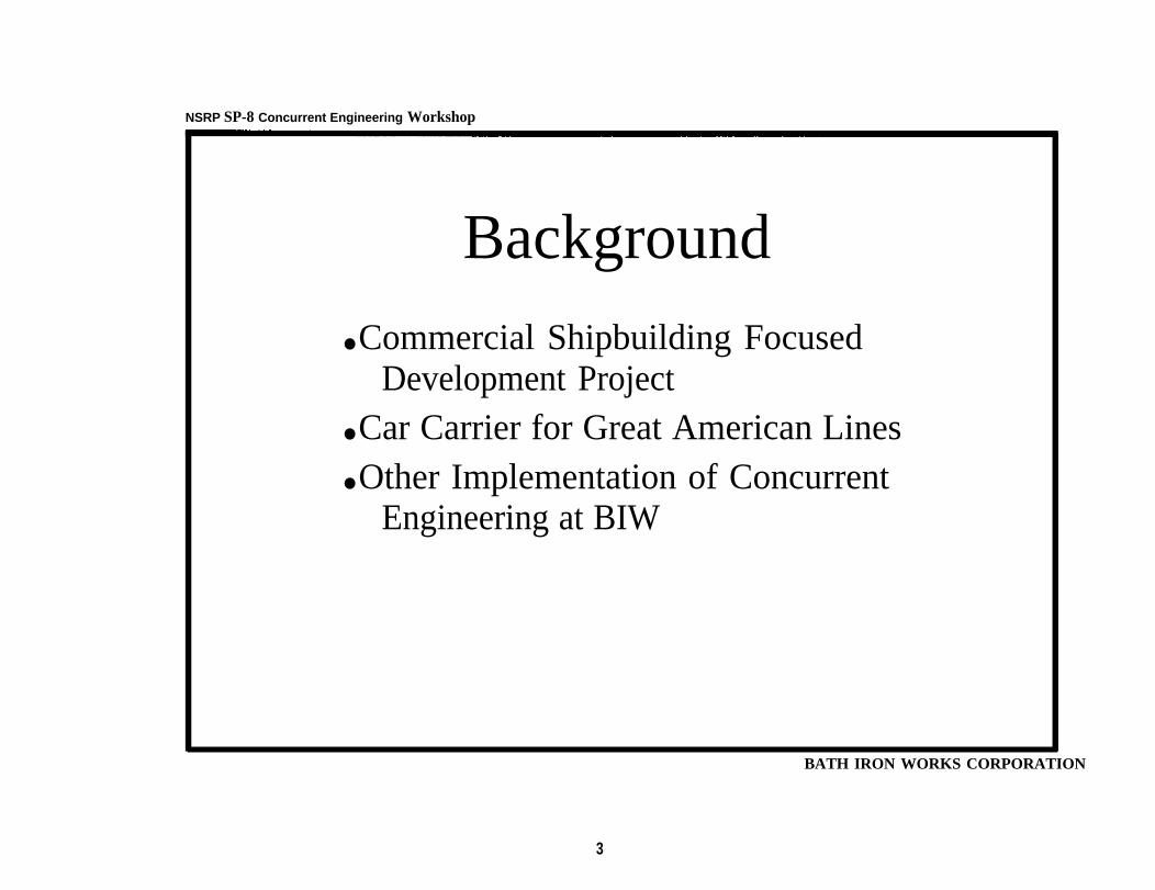
Background
● Commercial Shipbuilding FocusedDevelopment Project
● Car Carrier for Great American Lines● Other Implementation of Concurrent
Engineering at BIW
BATH IRON WORKS CORPORATION
3

NSRP SP-8 Concurrent Engineering Workshop
Commercial Shipbuilding FocusedDevelopment Project
• Contract awarded in the Fall of 1993 as part of thefirst round of ARPA awards
• Purpose is to design competitive commercialshipbuilding processes at Bath Iron Works
● Project offered an implementation vehicle for theNSRP Concurrent Engineering Project
D A

NSRP SP-8 Concurrent Engineering Workshop
Features of the Commercial ShipbuildingFocused Development Project
● Learning world-class processes and methods throughtechnology transfer from Kvaerner Masa-Yards and MitsuiEngineering and Shipbuilding
● Designing a facility to reflect competitive internationalpractice
● Designing ships for partners in the project, Great AmericanLines and American Automar
● Developing processes for competitive commercial shipDesign, Estimating, Planning, Materials, and Production
BATH IRON WORKS CORPORATION
5

●
●
●
Technology Transfer
Multi-functional BIW participation in travel toKvaerner Masa-Yards and Mitsui Engineering
NSRP SP-8 Concurrent Engineering Workshop
BATH IRON WORKS CORPORATION
and ShipbuildingPurpose of the trips wasexpertise in process and
to gain KMY and MESproduct technology
Trips were planned to emphasize integrationacross BIW functions; Marketing, Estimating,Planning, Design, Materials, and Production
7

NSRP SP-8 Concurrent Engineering Workshop
Technology Transfer Key Findings●
●
●
●
●
●
●
e
Small, flat, organizations relative to BIWAlignment of Design, Planning, Materials, ProductionorganizationsSignificant design effort prior to contract awardExperience maintained in a database of reference ship designsDesign functions have broader responsibility than at BIWIntegrated systems employed throughout the processReliance on infrastructure such as standards and stock materialFocus on least cost solutions
BATH IRON WORKS CORPORATION
8

NSRP SP-8 Concurrent Entgineering Workshop
Implementation of ConcurrentEngineering in the Project
● Design Strategy Workshop• Strategic Design• Process Based● Product and Process Measurement● Team Decision Making and Problem Solving● Team Dynamics Measurement• Presentation to management
● Accomplish Understanding
● Ownership of the Method
● Notice of Design Initiation
● Establishment of Product Development Team● Product Development Team Meetings
• Emphasis on process-based design; Planning, Materials,Production, aspects as well as Engineering
● Identified and worked issues
BATH IRON WORKS CORPORATION
10

NSRP SP-8 Concurrent Engineering Workshop
PILOT TEAM ORGANIZATION
AdvtsoryCommttee
BATH IRON WORKS CORPORATION
11

NSRP SP-8 Concurrent Engineering Workshop
BATH IRON WORKS CORPORATIONCONCURRENT ENGINEERING IMPLEMENTATION
Cross Disciplinary Teaming
Cross FunctionalTraining A
Technologies
Improvement
Direct Customer and
Process Based Design
Process andProduct Measurement
BATH IRON WORKS CORPORATION
12

NSRP SP-8 Concurrent Engineering Workshop
Strategic Design - Basis for CompetitiveProduct Delivery
Competitive OpportunityProduct FunctionsDesign BoundariesCompetitive FeaturesCompetitive Forces
Action Plan Product AttributesIndividual GoalsSchedules
Ranking
Management ApprovalQualitative Goal
Strategic Design Process
Measurement Innovative SolutionsQuantitative Goals Process Based Design
Multiple AlternativesIteration
BATH IRON WORKS CORPORATION
13

NSRP SP-8 Concurrent Engineering Workshop
Chosen Metrics for First Ship Design
Percent
● Affordability● Performance● Commonality● Producibility● Deliverability�
● Reliability● Maintainability.
BATH IRON WORKS CORPORATION
14

NSRP 5P-8 Concurrent Engineering Workshop
Concurrent Engineering ImplementationDesign Strategy Working Session -
OUTLINE
● PROCESS BACKGROUND• OPPORTUNITIES• STRATEGY• MEASURING PRODUCT SUCCESS• MEASURING PROCESS PERFORMANCE• ACTION PLAN
15


NSRP SP-8 Concurrent Engineering Workshop
Concurrent Engineering ImplementationDesign Strategy Working Session -
MEASURING PROCESS PERFORMANCE
TEAM EVALUATION TOOL
- TO BE COMPLETED NEXT WEEK AS A BENCHMARK AND IN 4 WEEKS TIME TOMONITOR PERFORMANCE
● Attributes MEASURED- TECHNICAL SKILL- DECISION-MAKING SKILL- ORGANIZATIONAL EFFICIENCY- OPEN-MINDED SPIRIT- LEADER/TEAM INTERACTION- COMMUNICATION- TECHNICAL FOCUS ON GOAL- INTERNAL TEAM INVOLVEMENT- EXTERNAL INVOLVEMENT- SENSE OF ACCOMPLISHMENT- PERSONAL SATISFACTION


NSRP SP-8 Concurrent Engineering Workshop
Benefits of Concurrent Engineering
Cross-Functional involvement from the outset ofdesign project Engineers with Planners, Designers, Production,
MaterialsInvolvement of OwnerLocal S6 involvement through teaming agreement
BATH IRON WORKS CORPORATION

NSRP SP-8 Concurrent Engineering Workshop
Difficu ties with Concurrent Engineering
● Basic Design process not understood by entire teamnot intuitive for engineers● Talking to one another
● Concensus takes time● PDT meetings not regular enough
BATH IRON WORKS CORPORATION
21

NSRP SP-8 Concurrent Engineering Workshop
Conclusions
● The Future for Concurrent Engineering at BIW – PCTC— Power plant generation barge
• Cross-functional teams developing process plansDDG51 Flight IIa
● Area teams developing design
BATH IRON WORKS CORPORATION
22


NSRP SP-8 Concurrent Engineering Workshop
●
●
●
●
●
●
Naval ArchitecturalGeneral ArrangementRORO Cargo Handling SystemReefer SystemHull FormMain Engine SelectionMachinery Arrangement
Issues
BATH IRON WORKS CORPORATION
24

NSRP SP-8 Concurrent Engneering Workshop.
Total Sea Transport LogisticsSystem
● Cargo handling is starting point of shipdesign process
● Most difficult area for US yards to establishexpertise
● Strategic Reliance on Suppliers● Tech Transfer instrumental in establishing
supplier contact
BATH IRON WORKS CORPOMTION
25

Sea Transport Logistics Chain
Cargo Owner


NSRP SP-8 Concurrent Engineering Workshop
RORO Requirements - “llities”
Commercial RORO- 6000 car- 65% Light Truck
Military RORO- MIAI Tank- Straight & Semi Tractor-Trailer- HMMV’S
24hr in-port turn-aroundSimple interface to ship
Trucks
Self-contained/modular cargo handlingsystems
BATH IRON WORKS CORPORATIO

NSRP SP-8 Concurrent Engineering Workshop
RORO CE Approach
● Customer involved from earliest stage- Sumitomo Contract Design- SRS Contract Design
● Thorough research of world fleet- World Wide Fleet Statistics- RORO Conference in Sweden
● Numerous discussions with owner’s reps- Visits to European Ship Customer’s
● Extensive visits made to ships in service- Visits to Sunbelt Dixie- Visits to Maersk Lines Ships in Portland
BATH IRON WORKS CORPORATION
29

NSRP SP-8 Concurrent Engineering Workshop
Military Vehicle StatisticsMilitary Deck Height Demand
BATH IRON WORKS CORPORATION

NSRP SP-8 Concurrent Engineering Workshop
RORO Fleet StatisticsDWT Vs. GT
60001
BATH IRON WORKS CORPORATION
31

NSRP SP-8 Concurrent Engineering Workshop
RORO CE Approach (cont’d)
● Commercial & Military Vehicle Statistics● Customer’s technical representative made
frequent visits to BIW● Strategic relationship with cargo handling
equipment suppliers- Expertise in development of cargo handling
systems- Visit to Cargo Elevator Supplier
● Equipment Supplier personnel on-site at BIW● In-process involvement of BIW production
planning personnel
BATH IRON WORKS CORPORATION
32

NSRP SP-8 Concurrent Engineeringl Workshop
RORO Producibility Issues
● Lessons Learned from States Lines RORO
● Ramp/Elevator Arrangement● Hoistable Deck Arrangement Vs Block
Breakdown● Arrangement of Vehicle Tie-Down Fittings
— . — - — BATH IRON WORKS CORPORATION
34

NSRP SP-8 Concurrent Engineering Workshop
Key RORO Metrics
● Deck Area/Height Distribution● Clear Span Between Columns● Vehicle Stowage Capacity● Vehicle Dimensions, Axle Loads● Vehicle Loading/Unloading Time● Ramp/Deck Deployment Time● Elevator Speed● Number of RORO Maneuvers
BATH IRON WORKS CORPORATION
35

Key RORO Metrics (cont’d)
● Number of Lift Deck Panels● Number of Ramps● Number of Install Parts● Length/Quantity of Hydraulic Piping● Number of Vehicle Tie-Down Fittings
BATH lRCIN WORKS CORPORATION

NSRP SP-8 Concurrent Engineering Workshop
●
●
●
●
●
RORO CE Results
Many iterations of ramp arrangements -optimized to suite mission requirementsAll military and commercial vehicle cargoobjectives were achievedMinimal use of hydraulicsCargo hold arrangement and placement ofelevators and ramps simplified - wing tanks,flush bulkheadsThree ship concept designs - S, L ,D - and two
I
variants - forward and aft facing stern ramp -were developed in less than 2 months I
BATH IRON WORKS CORPORATION
37

NSRP SP-8 Concurrent Engneering Workshop
RORO CE Results (cont’d)
● Block Breakdown worked concurrently withGA
• Cross training of planners in use of CAD tovisualize Block Breakdown
BATH IRON WORKS CORPORATION
39


NSRP SP.8 Concurrent Engneering Workshop
Reefer CE Approach
● Reefer system supplier brought in at veryearly stage
● Initial systems engineering received fromsupplier
● Cargo hold insulation / pIenum systemengineering developed by supplier
● Production Reps involved in suppliermeetings
● Customer heavily involved in educatingbuilder to nuances of Reefer trade
BATH IRON WORKS CORPORATION
41


NSRP SP-8 Concurrent Engneering Workshop
Reefer Producibility Issues
Reefer Plenum/Grating Arrangement- Robson Vs. conventional reefer grating system- Transverse Vs longitudinal air flow
Reefer Vent Trunk ArrangementUse of reefer fans for hold ventilationPre-Assembly of Reefer Cooling UnitsClearance for Reefer Plant Installation
BATH IRON WORKS CORPORATION
43

NSRP SP-8 Concurrent Engneering Workshonp
Key Reefer Metrics
● Install cost of Reefer Plant/cu ft ReeferCapacity
● Total Ship Cost/cu ft Reefer Capacity● Quantity of Insulation● Total Install Cost of Insulation● Number of Reefer Plant Install Parts● Number of Grating/Plenum Install Parts
B a r t h I R O N W O R K S C O R P O R A T I O N
45


NSRP SP-8 Concurrent Engineering Workshop
Hull Form CE Approach
Customer contacts established performanceexpectationsWorld-wide RORO fleet benchmarkInternal review of plate bendinglformingcapabilitiesStrategic relationships with world-class hydrodynamics test facilitiesVisit to Hydrodynamics LaboratoriesTech Transfer with KMY and MESComputational Fluid Dynamics
BATH IRON WORKS CORPORATION
49


NSRP SP-8 Concurrent Engineering Workshop—
Main Propulsion EngineRequirements - “llities” (cont’d)
● Sea Margin- 20% at Full Load Displacement
● Overhaul Interval● Maintainability
- Shaft Removal- Valve Cleaning- Piston Removal
BATH IRON WORKS CORPORATIO
55


.
NSRP SP-8 Concurrent Engineering Workshop
Main Propulsion Engine CEResults
● Slow Speed selected over medium speed● Seven Cylinder engine rated at full sea margin• Starboard side casing arrangement Block
Breakdown supports late installation● Shaft removal without cutting of web frames● Piston removal without special lifting fixtures
BATH IRON WORKS CORPORATION
58

NSRP SP-8 Concurrent Engineering Workshop
BATH IRON WORKS CORPORATION
Summary - Overall
● Development of international customer andsupplier relations is major challenge to USyards
● collocation of Core Team is essential● Group decision making requires considerable
effort● Effective in-process measurement is difficult
to achieve

NSRP SP-8 Concurrent Engineering Workshop
Summary - Costs
● Customer involvement requires clearbusiness relationship and agreement toparticipate prior to contract
● Need training and clear definition of supportteam organization and responsibilities
● collocation requires commitment of facilities● Standard metrics and methods needed to
achieve effective in-process designmeasurement
BATH IRON WORKS CORPORATION
60

NSRP SP-8 Concurrent Engineering Workshop
Summary - Benefits● Increased cost awareness of Engineers● Improved cost competitiveness of RCC(D)
Design● Improved Communications● Broader understanding of “total” ship design
problem● Higher confidence in design cost and
performance predictions● CE Approach has been adopted on all new
product development efforts - Power Barge,Flight IIA DDG, High Speed Monohull
BATH IRON WORKS CORPORATION
61

.- - -
NSRP SP-8 CONCURRENT ENGINEERING WORKSHOP
Structural Design-
Concurrent Engineering Experience
Stephen W . TarpyProject Structural Engineer
BATH IRON WORKS CORPORATION
62

NSRP SP-8 CONCURRENT ENGINEERING WORKSHOP
CE Decision Examples
use of bulb flat stiffeners
collarless construction/threadedelimination of box girdersframe/web/pillar spacingengine casing length
stiffeners
BATH IRON WORKS CORPORATION


NSRP SP-8 CONCURRENT ENGINEERING WORKSHOP
Early Decisions and DesignPrinciples
● no box beams and girders● avoid deck insert plates● avoid use of collars
. maximum panel size● maximum erected unit weight● design for robotics● built-up tees
BATH IRON WORKS CORPORATION

NSRP SP-8 CONCURRENT ENGINEERING WORKSHOP
Panel Stiffeners:Bulb Flats vs. Angles
Factors for consideration-• enhanced producibility● improved coating performance● heavier and deeper● no domestic sourcesApproach-• small team assigned ● regular meetings and actions over two months• data gathered by engineering, purchasing,
production and estimating● estimating compiled results
BATH IRON WORKS CORPORATION
66

NSRP SP-8 CONCURRENT ENGINEERING WORKSHOP
Panel Stiffeners:Bulb Flats vs. Angles
Conclusions-● small net cost reduction● production preference confirmed
● Holland profiles should be incorporated in design
● spec to be written to allow substitution of othershapes
BATH IRON WORKS CORPORATION

NSRP SP-8 CONCURRENT ENGINEERING WORKSHOP
Collarless Construction
● shallow deck structure required● traditional panel process dictates collars● understanding of alternatives evolved with tech
transfer visits
Conclusion-● new panel line must efficiently accommodate
threading stiffeners
BATH IRON WORKS CORPORATION
68

NSRP SP-8 CONCURRENT ENGINEERING WORKSHOP
Elimination of Box Girders
Conflicting motivations-● closed sections are easiest design solution● tees will be much more efficiently producedEngineering effort-● substantial time required for deck analysis● commitment to producibility provided incentive
Results-● no closed sections in the typical hull framing
system
BATH IRON WORKS CORPORATION
69


Shell Frame SpacingStudy-• 800 to 1000mm spacing considered. webs every 3,4, or 5 frames• pillars
Results
every 3, or 4 webs
●
●
●
frames at 830mm, webs at 3.32m, pillars at9.9620 frames including 5 webs per panel (16.6m)
efficient and useable for a range of ship lengths
BATH IRON WORKS CORPORATION
71

NSRP SP-8 CONCURRENT ENGINEERING WORKSHOP
Engine Casing Length
Principles-
● block breaks at multiples of panel length• desirable to fab casing within complete panels
Open item-. initial design failed to recognize block break
i s s u e• difficult to change (but will be)
BATH IRON WORKS CORPORATION

NSRP SP-8 (INDUSTRIAL ENGINEERING) PANEL
Concurrent Engineering-
A Planning Perspective
Paul LarochePrincipal Planner
BATH IRON WORKS CORPORATION
73

.
NSRP SP-8 (INDUSTRIAL ENGINEERING) PANEL
● Factors influencing the Planning Process with respect toConcurrent Engineering:– Future Facilities Upgrades (currently in pre-permitting phase)– Teaming initiatives (under current contract and future
an t ic ipa ted) – Increased Block Erection Weights– Increase in the size of Erection Blocks– Increased emphasis on Accuracy Control– Compressed Commercial Milestones Schedule– Influence to the Build Strategy as a result of knowledge gained
from KMY & Mitsui
BATH IRON WORKS CORPORATION
74

NSRP SP-8 (INDUSTRIAL ENGINEERING) PANEL
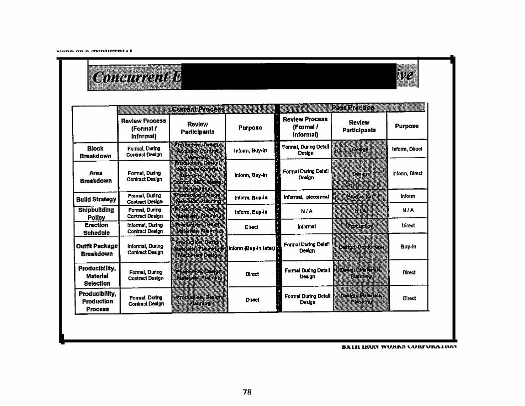
● Planning Products which were reviewed with Engineering,Production, Facilities and Materials Team:– Block Breakdown Scheme– Area Breakdown Scheme– Erection Schedule– Shipbuilding Policy Outline– Build Strategy Outline– Product Work Breakdown Structure (PWBS)– Principal Milestones– Outfit Packaging
BATH IRON WORKS CORPORATION
75

NSRP SP-8 (INDUSTRIAL ENGINEERING) PANEL
● Producibility Comments discussed with Engineering during theDesign Process– Frame spacing logic to
>> Optimize Future Facilities (Panel Line and Assembly Areas)>> Enhancing Product Repeatability
– Orientation of Engine Room Sea Bays to avoid Block BreaksLocation of Machinery Uptake Space Bulkhead in order tocompletely Package the Uptake Casing
– Simplifiy details around Stanchion Supports to avoid complex on-board fit-up..
BATH IRON WORKS CORPORATION
76

NSRP SP.8 (INDUSTRLAL ENGINEERING) PANEL
7 7

NSRP SP-8 (INDUSTRIAL ENGINEERING) PANEL
79

NSRP SP-8 Concurrent Engineering Workshop
PRODUCTION PARTICIPATIONWITHIN
CONCURRENT ENGINEERING
PROJECT PRODUCTION REPRESENTATIVE(OUTFITTING)
ANTHONY J. CLUKEYJUNE 1995
BATH IRON WORKS CORPORATION

FWRP SP-8 Concurrent Engineering Workshop
Concurrent Engineering ; Product ion’s Part ic ipat ion
Outline
• Reasons for Participation• Participation Considerations● Potential Roadblocks • Results to Date• Daily Considerations
BATH IRON WORKS CORPORATION

NSRP SP-8 Concurrent Engineering Workshop
Concurrent Engheering; Production’s Participation
Reasons For Participation
Nobody better understands the construction process.Short build times.Reduced rework.Best understanding of current Labor Contracts.Who better appreciates facility capabilities?Design ownership.Participation equals buy-in.Incorporation of lessons learned.
BATH IRON WORKS CORPORATION
82

NSRP SP-8 Concurrent Engineering Workshop
●
●
●
●
●
●
Concurrent Engineering; Production’s Participation
Participation Considerations
Expect criticism,Recognize and accept that no decision isRecognize that no one person has all the
– Networking is essential
an easy decision.answers.
Understand options, consider all aspects, and then proceed.Must be a team with a mission.Expect a feeling of satisfaction.
BATH IRON WORKS CORPORATION
83

NSRP SP-8 Concurrent Engineering Workshop
Concurrent Engineering; Production’s Participation
Potential Participation Roadblocks
●
●
●
●
Cultural Change
Alienation
Lack of “staying power”
Participant turnover
BATH IRON WORKS CORPORATION
84

NSRPsp-8 conrrent Engineering workshop
Concurrent Engineering; Production’s Participation
Participation Results to date
● A splinter group has been formed.
● This group will involve the right people at the right times.
● We’ve identified numerous characteristics for consideration.
Some of which are:
- durability
- required training
- unique safety issues ....hazardous materials
- material pricing
- material availability
85

NSRP SP-8 Concurrent Engineering Workshop
Concurrent Engineering; Production’s Participation
Participation Results to date (con’t)
●
●
Currentlyconsider.
we’re brainstorming potential candidates for the group to
A few of these items are:Potential use of thermoplastic pipe.
—
—
PotentialPotentialPotential
use of “spin flange” technology.use of standardized electrical foundations.use of single bulkhead penetration pieces.

NSRP SP-8 Concurrent Engineering Workshop
Concurrent Engineering; Production’s Participation
Items for Continuous Consideration
● Design with production very much in mind.• Simple design, if you please!
– No requirements for special tooling or jigs.– No requirements for special fittings.
● Pipe piece standardization.● Maximize downhand work.
• Maximize shop work.– “hot work” - shop– “cold work” - ship
BATH IRON WORKS CORPORATION
87

NSRP SP-8 Concurrent Engineering Workshop
●
●
●
●
Concurrent Engineering Production’s Participation
Summary
Short build times necessitate the use of concurrent engineering.Expect a roller coaster ride.Recognize that this is your opportunity to truly influence
Take satisfaction from your participation.
the process.
BATH IRON WORKS CORPORATIO

NSRP SP.8 CONCURRENT ENGINEERING WORK SHOP
B A T H I R O N W O R K S C O R P O R A T I O N
I N T E R N A T I O N A L S U P P L I E R D A T A B A S E
J U N E 9 , 1 9 9 5
B A T H I R O N W O R K S C O R P O R A T I O N
8 9

S U P P L I E R D A T A B A S E
O U T L I N E
BATH IRON WORKS CORPORATION
9 0

NSRP SP-8 CONCURRENT ENGINEERING WORKSHOP
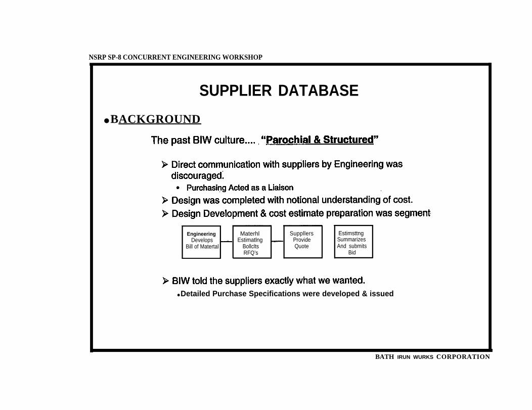
SUPPLIER DATABASE
“As the US. shipbuilding industry tries to enter the internationalcommercial shipbuilding market one thing becomes increasinglyclear; they must embrace an in-depth cultural change if they are tobe successful.One of the primary cultural changes that must take place is amanagement process that facilitates communication, collaboration,and rapid decision making of all parties involved in the ship designand construction process."
Robert SchaffranProgram Manager, MARITEC
BATH IRON WORKS CORPORATION
91
NSRP SP-8 CONCURRENT ENGINEERING WORKSHOP
SUPPLIER DATABASE
● BACKGROUND
Engineering Materhl Suppllers EstimsttngDevelops Estimatlng Provide Summarizes
Bill of Matertal Bollclts Quote And submitsRFQ’s Bid
● Detailed Purchase Specifications were developed & issued
BATH IRUN WURKS CORPORATION

NSRP SP-8 CONCURRENT ENGINEERING WORKSHOP
SUPPLIER DATABASE
BATH IRON WORKS CORPORATION
93

NSRP SP-8 CONCURRENT ENGINEERING WORKSHOP
SUPPLIER DATABASE
BACKGROUND:
common repository to share the knowledge being obtained neededto be established.
objectives:1. Develop a method to determine who BIW will do business with.
2. Support Proposal Development Efforts�● Historical Pricing records for Major Equipment.● Major Equipment Lists for various ship designs maintained in one place.
BATH IRON WORKS CORPORATION
94


NSRP SP-8 CONCURRENT ENGINEERING WORKSHOP
SUPPLIER DATABASED A T A B A S E S T R U C T U R E :
supplier module which tracks the following:
Numeric Designation (WBS) Equipment Description Qualification StatusVendor Name Vendor AddressVendor Contact & Title Vendor Phone/Fax
Engineering and will provide the following data:Numeric Designation (WBS) Equipment Shipset QuantityDescriptions Fluid MaterialColor Capacity HeadClassification Society Pressure Pressure DropTemp Heat Dissipation EfficiencyDry Weight Wet Weight PowerDimensions Electric Power FactorVoltage Phases AC/DCEnclosure Type Documentation RequiredSystem/Equip. Identifiers Reservations/Comments
BATH IRON WORKS CORPORATION
96

NSRP SP-8 CONCURRENT ENGINEERING WORKSHOP
SUPPLIER DATABASE
DATABASE STRUCTURE:
Through the use of queries, the vendor information from the suppliermodule will be linked to a specific ship’s Master Equipment List tofacilitate the RFQ process.The Priced MEL module of the database will be maintained by theMaterials Division and track the following information for each shipestimate completed:
Numeric Designation (WBS) Equipment DescriptionVendor Quoting Price Quoted (in $ US)Lead-time Price ValidityNotes/Comments
BATH IRON WORKS CORPORATION
97


NSRP SP-8 CONCURRENT ENGINEERING WORKSHOP
SUPPLIER DATABASEDATABASE CAPABILITIES:
the database.Ž Materials - Supplier Information, Past pricing for price analysis, etc.Ž Engineering - Material Cost Information, Notional Bills of material, etc.• Estimating - Material cost data for high-level analysis
Ž Makers List to support Proposal SubmittalsŽ Mailing listsŽ Notional Bills of Material for Commercial Ship designs• Weight reports
• Quote history for different equipments/materialsŽ Long Lead-time material reports
• Facilitate future bill of material development.
BATH IRON WORKS CORPORATION
99


NSRP SP-8 Concurrent Engineering Workshop
CE IMPLEMENTATIONMeasurement
● The “Rules” of Design Measurement- Team develops measurement goals & tools– Measure what’s important, not what’s easy to measure- Direction is more important that precision .- Measure in-process- Measure often- Measure all parameters concurrently- Use a visual presentation of results
101

CE IMPLEMENTATIONMeasurement
● Project Strategy
1. Affordability Achieve a competitive ship price
2. Performabillty Meet all specified owners /regulatory requirements for performance
3. Standardability Maximize the use of common parts, components, and processes
4. Producibility Maximize the use of efficient BIW processes to produce the product
5. Deliverabiiity Ability to get the product from concept to delivery withincontractual time period.
6. Riskability Design in adequate margins to achieve high probability ofproduct project success
7. Reliabiiity Make use of proven components, simple and easy to maintainsystems and proven technology coating systems
8. Maintalnabliity Minimize frequency of maintenance intervals and effort required tomaintain the ship in service
BATH RON WORKS CORPORATION

NSRP SP-8 Concurrent Engineering Workshop
CE IMPLEMENTATIONMeasurement
● In-process MeasurementStrateg icIlity Measurements
1. Affordability Projected total ship cost in US$
2. Performability Number of comments against approval drawings
3. Standardability % Commonality of processes and catalog parts
4. Produceability Projected product labor hours. Total ship hours/ton steel weigh
5. Deliverability Months to deliver finished ship
6. Riskability Projected vs. target total ship $ cost
7. Reliability Maintenance intervals for major equipment
8. Maintainability Subjective maintenance evaluation projection by team
BATH IRON WORKS CORPORATION
103

NSRP SP-8 Concurrent Engineering Workshop.
.
CE IMPLEMENTATIONMeasurement
● In-process MeasurementAFFORDABILITY
MAINTAINABILITY
RELIABILITY MAlNT. STANDARDABILITY
RISKABILIT PRODUCIBILITY
HRS/TONNE
DELIVERABILITY I MONTHS
BATH IRON WORKS CORPORATION

zo

NSRP SP-8 Concurrent Engineering Workshop`
CE IMPLEMENTATIONMeasurement
● Riskability Analysis- Design .– Developmental ship systems- Installation experience– New production facilities
BATH IRON WORKS CORPORATION
I
106

; 1
slow Speed Excessive installation hours, poor component n/a n/a : undefined Strong supplier support, In-house trainingDiesel :performance, schedule degradation ,Cargo Handling Excessive installation hours, poor component n/a n / a I undefined i Strong supplier support, in-house trainfngSystems I performance, schedule degradation I I 1
107

. .
Reefer System Excessive installation hours, poor component ‘n/a In/a I undefined Strong supplier support, In-house trainingIperforrnance, schedule degradation I
i I I 1
Processes 1 i
New Facility Startup problems with new facility, failure of Ii
I Realistic learning curve, in-house trainingdevelopmental production processes to
1,
! p e r f o r r n d e s i g n e d ICommercial ; Unanticipated problems in adopting new Realistic learning curve and accuracy conlrolStandards : standards, costs associated with inadvertent I plan including in-house training
: use of Navy standards 1
Accuracy Unanticipated problems in adopting MES type I Realistic learning curveControl : accuracy control plan, failure of plan to
:facilitate Installation of dimension criticalt
components such as movable decks, pallet“elevator system
Design Slower than planned Iearnlng of new design Careful selection of tools and processesTools/Processes techniques, software, processes. Failure of including pre-purchase testing where
, software and/or processes to perform as I appropriate, realistic learning curve, in-houseexpected. I i training *

z0


NSRP SP-8 Concurrent Engineering Workshop
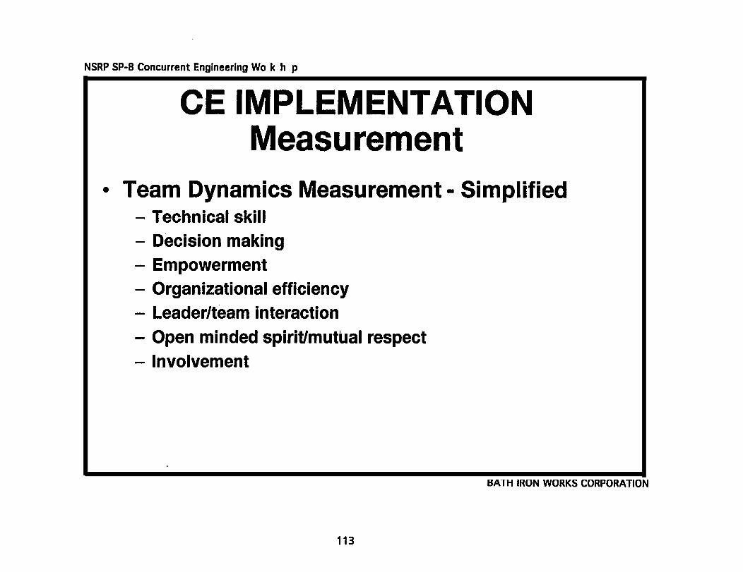
CE IMPLEMENTATION Measurement
● Team Dynamics MeasurementTechnical skillDecision makingOrganizational efficiencyOpen minded spiritLeader/team interactionCommunicationTechnical focus on goalInternal team. involvementExternal involvementSense of accomplishmentPersonal satisfaction
BATH IRON WORKS CORPORATION
111

a0u

Additional copies of this report can be obtained from theNational Shipbuilding Research Program Coordinator of theBibliography of Publications and Microfiche Index. You can
call or write to the address or phone number listed below.
NSRP CoordinatorThe university of Michigan
Transportation Research InstituteMarine systems Division
2901 Baxter Road.Ann Arbor, MI 48109-2150
Phone: (3 13) 763-2465Fax (313) 936-1081