revision 1 - us department of energy readiness assessment (tra) / technology maturation plan (tmp)...
TRANSCRIPT

U.S. Department of Energy
Office of Environmental Management
Technology Readiness Assessment (TRA)
/ Technology Maturation Plan (TMP)
Process Implementation Guide
Revision 1
August 2013

U.S. DOE Office of Environmental Management Revision 1, August 2013 TRA/TMP Process Implementation Guide Page 2 of 76
REVISION LOG
Date Reason for Revision
Revision 0, March 2008
Initial issue of EM guide
Revision 1, August 2013
Updates based on lessons learned from completed TRAs Incorporation of “working draft” appendices on TRL 7 calculator,
and Process Control / Software TRAs
Changes are not tracked.

U.S. DOE Office of Environmental Management Revision 1, August 2013 TRA/TMP Process Implementation Guide Page 3 of 76
TABLE OF CONTENTS
1.0 INTRODUCTION ........................................................................................................................... 6
2.0 OVERVIEW OF TECHNOLOGY READINESS ASSESSMENTS AND TECHNOLOGY MATURATION PLANS ................................................................................................................. 7
2.1 Objectives of TRAs and TMPs ............................................................................................... 72.2 The TRA ................................................................................................................................. 72.3 The Technology Maturation Plan ......................................................................................... 122.4 The Relationship of TRAs and TMPs to DOE Critical Decisions ....................................... 132.5 The Relationship of TRAs and TMPs to Other Reviews ..................................................... 152.6 The Relationship of TRAs and TMPs to Risk Management ................................................ 16
3.0 TECHNOLOGY READINESS ASSESSMENT PROCESS ........................................................ 183.1 Process Overview ................................................................................................................. 183.2 Key Roles and Responsibilities ............................................................................................ 20
3.2.1 EM Program Office ...................................................................................................... 203.2.2 EM Cognizant Program Office for TRAs ..................................................................... 203.2.3 Federal Project Director (or Operations Activity Federal Program Lead) ................... 203.2.4 Federal Project/Program Liaison .................................................................................. 203.2.5 Contractor ..................................................................................................................... 203.2.6 Contractor Liaison ........................................................................................................ 213.2.7 TRA Team Leader ........................................................................................................ 213.2.8 TRA Team Members .................................................................................................... 22
3.3 TRA Team Independence ..................................................................................................... 223.4 TRA Planning Stage ............................................................................................................. 23
3.4.1 TRA Plan ...................................................................................................................... 253.4.2 Documentation for Review ........................................................................................... 253.4.3 On-site Assessment Facilities, Resources, and Logistics ............................................. 26
3.5 TRA Execution Stage ........................................................................................................... 283.5.1 On-Site Assessment Meeting ....................................................................................... 293.5.2 Critical Technology Elements (CTE) Identification..................................................... 303.5.3 Technology Readiness Level Assessment .................................................................... 313.5.4 Due Diligence Reviews ................................................................................................ 323.5.5 TRA Report .................................................................................................................. 323.5.6 Factual Accuracy .......................................................................................................... 333.5.7 TRA Results Briefing ................................................................................................... 33
4.0 TECHNOLOGY MATURATION PLAN ..................................................................................... 354.1 Process Overview ................................................................................................................. 354.2 TMP Preparation .................................................................................................................. 354.3 TMP Document .................................................................................................................... 364.4 Test Plans and Change Packages .......................................................................................... 374.5 TMP Execution ..................................................................................................................... 37
5.0 TRA/TMP Lessons Learned .......................................................................................................... 38

U.S. DOE Office of Environmental Management Revision 1, August 2013 TRA/TMP Process Implementation Guide Page 4 of 76
6.0 ATTACHMENTS .......................................................................................................................... 39Attachment A, TRA Plan ................................................................................................................. 40Attachment B, On-Site Assessment Meeting Agenda ..................................................................... 41Attachment C, TRA Results Briefing Agenda ................................................................................. 42Attachment D, TRA Report Format ................................................................................................. 43Attachment E, Technology Maturation Plan Format ....................................................................... 45Attachment F, TRA Summary ......................................................................................................... 48Attachment G, Critical Technology Elements (CTE) Identification Criteria .................................. 49Attachment H, Technology Readiness Level Calculators ................................................................ 50
7.0 APPENDICES ............................................................................................................................... 68Appendix 1, TRL 7 Calculator ......................................................................................................... 69Appendix 2, TRA Guidance for Evaluating Process Control Systems and Process-Related Software Development .................................................................................................................................... 74
LIST OF FIGURES
Figure 1 Schematic of DOE Technology Readiness Levels ................................................................... 8Figure 2 Suggested Technology Readiness Assessments and Other Reviews for Critical Decisions .. 13Figure 3 TRAs, TMPs, Technology, and Risk Management ............................................................... 17Figure 4 TRA/TMP Process ................................................................................................................. 18
LIST OF TABLES
Table 1 Technology Readiness Levels ................................................................................................... 9Table 2 TRL Scale, Fidelity, and Environment Definitions ................................................................. 10Table 3 TRL Testing Definitions ......................................................................................................... 10Table 4 Examples of TRL Stages ......................................................................................................... 11Table 5 Typical TRA Timeline ............................................................................................................ 19Table 6 Typical TMP Timeline ............................................................................................................ 19Table 7 Implementation Tips for TRA Planning .................................................................................. 27Table 8 Implementation Tips for TRA Execution ................................................................................ 34Table 9 TRA/TMP Lessons Learned .................................................................................................... 38

U.S. DOE Office of Environmental Management Revision 1, August 2013 TRA/TMP Process Implementation Guide Page 5 of 76
LIST OF ACRONYMS AND ABBREVIATIONS
ALARA BCP CD CTE DoD DOE DSA EM EM CPOT ETR FPD FPL G ICR IPR IPT LOI M M&S NASA NNSA O ORR P PDSA POA R&D RAMI S&T STD SOPP
TMP
TRL
TSRWPS
As Low As Reasonably Achievable Baseline Change Proposal Critical Decision Critical Technology Element U.S. Department of Defense U.S. Department of Energy Documented Safety Analysis U.S. Department of Energy’s Office of Environmental Management EM Cognizant Program Office for TRAs External Technical Review Federal Project Director Federal Program Lead Guide Independent Cost Review Independent Project Review Integrated Project Team Lines of Inquiry Manufacturing and quality Modeling and Simulation U.S. National Aeronautics and Space Administration National Nuclear Security Administration Order Operational Readiness Review Programmatic, customer focus, documentation Preliminary Documented Safety Analysis Plan of Action Research and Development Reliability, Availability, Maintainability, Inspectability Science and Technology Standard Standing Operating Policies and ProceduresTechnology, technical aspects Technology Element Technology Maturation Plan Technology Readiness Assessment Technology Readiness Level Technical Safety Requirements Waste Processing System
T TE
TRA
TSR

U.S. DOE Office of Environmental Management Revision 1, August 2013 TRA/TMP Process Implementation Guide Page 6 of 76
1.0 INTRODUCTION
This Guide is the U.S. Department of Energy’s Office of Environmental Management’s (EM’s) program guidance for implementing Technology Readiness Assessment (TRA)/ Technology Maturation Plans (TMP) guidance in Department of Energy (DOE) Guide 413.3-4, Technology Readiness Assessment Guide. DOE Guide 413.3-4A provides suggested guidance to DOE and National Nuclear Security Administration (NNSA) program offices on conducting TRAs, developing TMPs and developing program specific guidance. This EM Guide is for use by all EM elements.1 Guides are not requirements documents, and are not tobe construed as requirements in any audit or appraisal for compliance with the parent Policy, Order, Notice, or Manual.
EM began piloting its TRA/TMP process in 2006. The initial version of the EM Technology
Readiness Assessment (TRA)/Technology Maturation Plan (TMP) Process Guide was published in March 2008. Lessons learned from the conduct of seven TRAs completed since March 2008 have been incorporated in this revision.
This Guide is written to support the conduct of a TRA by an independent team, as well as the development of a plan to mature the technologies, the TMP, which is completed by the project/program. Projects and programs may also use this guide to assist them in performing a self-assessment of their technology readiness and then develop plans to mature technologies, and manage and control technology development and deployment.
It is recommended that projects/programs use this Guide to conduct a self-assessment of the technology readiness and develop an initial TMP prior to an independent TRA. This approach improves the overall efficiency of the TRA process, while providing a basis for management and control of the technology development and deployment activities conducted by the project/program. Revisions to the TMP may be required as a result of the independent TRA.
The user of this Guide is cautioned in using only the technology readiness level metric as the single criterion for deciding between competing alternatives. The bases for the decision should include the degree of difficulty to mature the technology alternatives to the desired level, including consideration of risks, cost, and schedule associated with the technology maturation process.
Projects/programs with existing TMPs should consider updating the TMP to the guidance in this revision of the Guide after their next TRA.
This Guide is intended to be a “living document” and will be modified periodically as lessons learned from implementing the TRA/TMP processes are identified.
1 EM Standing Operating Policies and Procedures (SOPP) #27, Technical Readiness Assessments/Technology Maturation Planning.

U.S. DOE Office of Environmental Management Revision 1, August 2013 TRA/TMP Process Implementation Guide Page 7 of 76
2.0 OVERVIEW OF TECHNOLOGY READINESS ASSESSMENTS AND
TECHNOLOGY MATURATION PLANS
This implementation Guide has been developed based on experience with tank waste and nuclear material processing systems or similar types of technology development and implementation activities. The TRA process in this Guide is applicable to all EM elements including Mission Unit functional areas such as soils and groundwater, and field offices. Modifications to the TRA process guidance necessary to conducte the TRA of the program under evaluation should be documented during the planning process for the TRA.
As part of the continuous improvement process, changes to the definitions and criteria, including approaches for assessing different types of technology systems such as software systems and late stage technology assessments (i.e., Technology Readiness Level (TRL) 7 through TRL 9), will be implemented in stages. The first stage will be to develop the draft assessment tools (i.e., TRL calculator criteria, checklists, etc.), and then the tools will be piloted during an appropriate technology assessment. Lessons learned will be applied to refine the tools. Finally, TRL calculators/tools will be incorporated in this Guide such that they can be applied to EM projects/programs in a consistent manner. This revision of the Guide includes “working draft” appendices of the TRL 7 calculator and guidance for conducting software TRA. These appendices are included here for information. TRA teams are encouraged to use and provide feedback to the EM office responsible for this guide. After these guides are piloted during appropriate technology assessments, they will be updated and fully incorporated in the guide.
2.1 Objectives of TRAs and TMPs
In accordance with DOE Order 413.3B, Program and Project Management for the
Acquisition of Capital Assets, TRAs and TMPs are required for Major Systems Projects (i.e., those with total project cost greater than $750M) prior to Critical Decision (CD) 2. However, they are also highly recommended for smaller projects, as well as Operations Activities, such as technology demonstrations, which involve the development and implementation of new technologies or technologies in new operational environments. Operations Activities are EM’s non-capital asset activities that adhere to many of the same management principles as projects.
Results of TRAs provide a snapshot in time of the maturity of technologies and their readiness for insertion into the design process and execution schedule for projects or Operations Activities. TMPs detail the steps necessary for developing technologies that are less mature than desired to the point where they are ready for project insertion. TRAs and TMPs are effective management tools for reducing technical risk and the potential for technology driven cost increases and schedule delays.
2.2 The TRA
The TRA is a systematic, metric-based assessment of how far technology development has progressed. It is not a pass/fail exercise, and is not intended to provide a value judgment of the technology developers or the technology development program. A TRA can:

U.S. DOE Office of Environmental Management Revision 1, August 2013 TRA/TMP Process Implementation Guide Page 8 of 76
Identify the gaps in testing, demonstration and knowledge of a technology’s currentreadiness level and the information and steps needed to reach the readiness levelrequired for successful inclusion in the project;
Identify at-risk technologies that need increased management attention or additionalresources for technology development; and
Increase the transparency of management decisions by identifying key technologiesthat have been demonstrated at certain levels of maturity or by highlighting immatureor unproven technologies that might result in increased project risk.
A TRA evaluates technology maturity using the TRL scale that was pioneered by the National Aeronautics and Space Administration (NASA) in the 1980s. A TRL indicates the maturity of a given technology according to the definitions and descriptions in Table 1 (Note: these may require modification for non-waste processing applications, see section 3.4.1). TRLs provide a common language and measurement scale to enhance communication within and between the science and technology and project/program communities, both in government and industry. Figure 1 provides a schematic of the meaning of the TRLs in the context of EM projects and Operations Activities. The TRL scale ranges from 1 (basic principles observed) through 9 (total system used successfully in project operations).
Figure 1 Schematic of DOE Technology Readiness Levels
Caution
TRLs should not be used as a basis for comparing competing technologies. A TRL, by itself, does not give an indication of the difficulty to advance the maturity of the technology, that is the risks, scope, schedule, and costs associated with developing a technology to desired levels of maturity. A technology judged to have a relatively low TRL (e.g., 3) may be easier and less costly to develop to TRL 6 than a technology with a higher TRL (e.g., 5).

U.S. DOE Office of Environmental Management Revision 1, August 2013 TRA/TMP Process Implementation Guide Page 9 of 76
Table 1 Technology Readiness Levels Relative Level
of Technology
Development
Technology
Readiness
Level
TRL Definition Description
System
Operations TRL 9
Actual system operated over the full range of expected conditions.
Actual operation of the technology in its final form, under the full range of operating conditions. Examples include using the actual system with the full range of real wastes.
System
Commissioning
TRL 8
Actual system completed and qualified through test and demonstration.
Technology has been proven to work in its final form and under expected conditions. In almost all cases, this TRL represents the end of true system development. Examples include developmental testing and evaluation of the system with real waste in hot commissioning.
TRL 7
Full-scale, similar (prototypical) system demonstrated in a relevant environment
Prototypea full scale system. Represents a major step up from TRL 6, requiring demonstration of a system prototype in a relevant environment. Examples include testing the prototype in the field with a range of simulants and/or real waste and cold commissioning.
Technology
Demonstration TRL 6
Engineering scale, similar (prototypical) system validation in a relevant environment
Representative engineering scale system, which is well beyond the scale tested for TRL 5, is tested in a relevant environment. Represents a major step up in a technology’s demonstrated readiness and system integration. Examples include testing a prototype with real waste and a range of simulants.
Technology
Development
TRL 5
Laboratory/bench scale, similar system validation in relevant environment
The basic technological components are integrated so that the system configuration is similar to (matches) the final application in almost all respects. Examples include testing a high-fidelity system in a simulated environment and/or with a range of real wastes and simulants.
TRL 4
Component and/or system validation in laboratory environment
Basic technological components are integrated to establish that the pieces will work together. This is relatively "low fidelity" compared with the eventual system. Examples include integration of “ad hoc” hardware in a laboratory and testing with a range of simulants.b Laboratory/bench scale testing may not be appropriate for all systems. For example, mechanical systems, such as robotic retrieval technologies, may require full scale prototype testing to meet TRL 4.
Research to
Prove
Feasibility
TRL 3
Analytical and experimental critical function and/or characteristic proof of concept
Active research and development is initiated. This includes analytical studies and laboratory/bench scale studies to physically validate the analytical predictions of separate elements of the technology. Examples include components that are not yet integrated or representative. Components may be tested with simulants. For some applications, such as mechanical systems, this may include computer and/or physical modeling to demonstrate functionality.
TRL 2
Technology concept and/or application formulated
Invention begins. Once basic principles are observed, practical applications can be invented. Applications are speculative, and there may be no proof or detailed analysis to support the assumptions. Examples are still limited to analytic studies.
Basic
Technology
Research TRL 1
Basic principles observed and reported
Lowest level of technology readiness. Scientific research begins to be translated into applied research and development (R&D). Examples might include paper studies of a technology’s basic properties.
a A prototype is defined as a physical or virtual model used to evaluate the technical or manufacturing feasibility or utility of a particular technology or process, concept, end item, or system.b If feasible, it is recommended to include tests on a limited range of real waste prior to achieving TRL 4.

U.S. DOE Office of Environmental Management Revision 1, August 2013 TRA/TMP Process Implementation Guide Page 10 of 76
A TRL is not an indication of the quality of technology implementation in the design. However, technology testing results are critical in determining the TRL. Testing should be conducted in the proper environment and the technology tested should be of an appropriate scale and fidelity. TRL definitions regarding testing “scale,” “system fidelity,” and “environment” are provided in Tables 2 and 3.
Table 2 TRL Scale, Fidelity, and Environment Definitions
Scale
Full Plant Scale Matches final application Engineering Scale1 Typically (1/10 < system < Full Scale) Laboratory/Bench1 Typically < 1/10 Full Scale
1 The Engineering Scale and Laboratory/Bench scale may vary based on engineering judgment.
System Fidelity
Identical System Configuration Matches final application in all respects Similar Systems Configuration Matches final application in almost all respects Pieces System matches a piece or pieces of the final application Paper System exists on paper (i.e., no hardware system)
Environment (Waste)
Operational (Full Range) Full range of actual waste Operational (Limited Range) Limited range of actual waste Relevant Simulants plus a limited range of actual wastes2 Simulated Range of simulants
2 Simulants should bound relevant physical and chemical properties. Testing should be conducted with as wide a range of actual waste as practicable, consistent with waste availability, safety, As Low As Reasonably Achievable (ALARA), cost, and project risk.
Table 3 TRL Testing Definitions
TRL Level Scale of Testing Fidelity Environment1,2
9 Full Identical Operational (Full Range) 8 Full Identical Operational (Limited Range) 7 Full Similar Relevant 6 Engineering Similar Relevant 5 Laboratory/Bench Similar Relevant 4 Laboratory/Bench Pieces Simulated3 3 Laboratory/Bench Pieces Simulated 2 Paper 1 Paper 1 Simulants should match relevant physical and chemical properties 2 Testing should be conducted with as wide a range of actual waste as practicable; and consistent with waste
availability, safety, ALARA, cost, and project risk 3 If feasible, it is recommended to include tests on a limited range of real waste tests.

U.S. DOE Office of Environmental Management Revision 1, August 2013 TRA/TMP Process Implementation Guide Page 11 of 76
The range and type of EM projects that may undergo a TRA represent a diverse range of technologies and level of complexity. Table 4 provides examples of how technologies may progress in maturity2. See TRL Calculators in Attachment H for the full listing of attributes.Table 4 Examples of TRL Stages
TRL Low Activity Waste (LAW) Vitrification Advanced Neutron Absorber (ANA)
Development
9 Hot operations of the LAW plant DOE Spent Nuclear Fuel (SNF) packaged withANA accepted at geologic repository fordisposal
8 Hot commissioning of the LAW plant Nuclear Regulatory Commission issueslicenses for spent fuel storage, transportation,and disposal systems using ANA
7 Cold commissioning of the LAW plant Manufacturing of commercial size ingots (10klb) demonstrated including ingot reduction toplate
Full size SNF baskets using ANA arefabricated
American Society for Testing and Materials(ASTM) grants final material specification
American Society of Mechanical Engineersgrants code case for use in welded structuralapplications
6 Operation of a one-third scale LAW melter system using simulants
Continued glass formulation developmentusing crucible and small-scale melter testing of actual waste and simulants
Manufacturing of 3000 pound ingotsdemonstrated including ingot reduction to plate
5 Development and laboratory/bench scaletesting of melter systems including feed andoff gas systems
Crucible testing using actual wastes Continued glass formulation development to
optimize glass properties and performance
Investigations into scale-up from 300 poundingots completed.
Secondary melt process parameters determined
4 Waste characterization continues Small-scale testing of melter technologies and
systems Continued glass formulation testing to
determine potential glass compositions, wasteloadings, and durability while maintainingacceptable properties
Manufacturing of 300 pound ingotsdemonstrated including ingot reduction to plate
ASTM grants provisional materialspecification
3 Waste characterization continues Crucible size tests to determine potential glass
formulations for immobilizing LAW Determination of glass properties needed for
successful processing and performance Investigation of melter technologies
Button-size ingots prepared Manufacturing of 50 pound ingots
demonstrated including ingot reduction to plate Material property characterization including
welded specimens
2 Investigation of the structure, durability, andability of glass to incorporate a variety ofelements
Waste characterization begins
Thermodynamic modeling of melt chemistrycompleted
Microstructural characterization1 Fundamental investigations of glass chemistry
and structure
2 The examples in Table 4 are not meant to be characteristics for measuring contractual performance, nor do they necessarily represent an actual account of project history or progress.
U.S. DOE Office of Environmental Management Revision 1, August 2013 TRA/TMP Process Implementation Guide Page 12 of 76
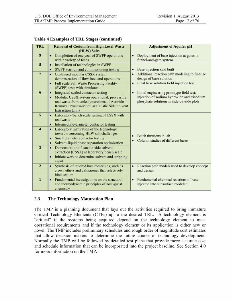
Table 4 Examples of TRL Stages (continued)
TRL Removal of Cesium from High Level Waste
(HLW) Salts
Adjustment of Aquifer pH
9 Completion of one year of SWPF operationswith a variety of feeds
Deployment of base injection at gates infunnel-and-gate system
8 Installation of technologies in SWPF SWPF start-up and commissioning testing Base injection skid built
Additional reaction path modeling to finalizedesign of base solution
Final base solution field injection test
7 Continued modular CSSX systemdemonstration of flowsheet and operations
Full scale Salt Waste Processing Facility(SWPF) tests with simulants
6 Integrated scaled contactor testing Modular CSSX system operational, processing
real waste from tanks (operations of ActinideRemoval Process/Modular Caustic Side SolventExtraction Unit)
Initial engineering prototype field test;injection of sodium hydroxide and trisodiumphosphate solutions in side-by-side plots
5 Laboratory/bench scale testing of CSSX withreal waste
Intermediate-diameter contactor testing
Batch titrations in lab Column studies of different bases
4 Laboratory maturation of the technologytoward overcoming HLW salt challenges
Small diameter contactor testing Solvent-liquid phase separation optimization
3 Demonstration of caustic-side solventextraction (CSSX) at laboratory/bench scale
Initiate work to determine solvent and strippingagent
2 Synthesis of tailored host molecules, such ascrown ethers and calixarenes that selectivelybind cesium
Reaction path models used to develop conceptand design
1 Fundamental investigations on the structuraland thermodynamic principles of host-guestchemistry
Fundamental chemical reactions of baseinjected into subsurface modeled
2.3 The Technology Maturation Plan
The TMP is a planning document that lays out the activities required to bring immature Critical Technology Elements (CTEs) up to the desired TRL. A technology element is “critical” if the systems being acquired depend on the technology element to meet operational requirements and if the technology element or its application is either new or novel. The TMP includes preliminary schedules and rough order of magnitude cost estimates that allow decision makers to determine the future course of technology development. Normally the TMP will be followed by detailed test plans that provide more accurate cost and schedule information that can be incorporated into the project baseline. See Section 4.0 for more information on the TMP.

U.S. DOE Office of Environmental Management Revision 1, August 2013 TRA/TMP Process Implementation Guide Page 13 of 76
2.4 The Relationship of TRAs and TMPs to DOE CDs
DOE Guide 413.3-4A and EM recommend conducting TRAs during conceptual design and preliminary design processes; at least 90 days prior to CD milestones. Figure 2 shows how TRAs and other key reviews support each of the CDs. The TRA/TMP process serves as one of the tools employed to help evaluate development progress and obtain CD approval. There are numerous additional requirements for each CD, see DOE O 413.3B.
Figure 2 Suggested Technology Readiness Assessments and Other Reviews for Critical
Decisions
Small projects and Operations Activities have phases and reviews similar to those depicted in Figure 2. TRAs and TMPs are not typically required for these smaller projects and Operations Activities, but are considered a good management practice, and highly recommended.
DOE has adopted TRL 6 as the maturity level normally necessary before a technology can be incorporated into final design which correlates to CD-2. EM has designated TRLs 7, 8, and 9 as levels associated with cold commissioning, hot commissioning, and hot operations, respectively. Prior to start of operations, start-up testing and operational readiness reviews should ensure that the CTEs have advanced to the target maturity (TRL 6 toward TRL 9), as applicable and appropriate. Many of the aspects related to technical maturity are assessed as part of these reviews. TRL calculator tables, or a similar tool, for these late stage maturity levels have yet to be developed for EM cleanup projects. They are planned to be developed and piloted during upcoming reviews, and then incorporated into the next revision of this Guide. Until that time, the Federal Project Director (FPD), or the Federal Program Lead (FPL) for an Operations Activity3, is responsible for ensuring planned turnover, startup and readiness reviews address technology maturity aspects to ensure the system is ready to transition to hot operations. Appendix 1 is a “working draft” of the TRL 7 calculator table. 3 The FPL for an Operations Activity is also referred to as the Operations Activity Manager in other EM documents.
Mission Alternative Performance Construction Operations
Need Selection Baseline Start Start
CD-0 CD-1 CD-2 CD-3 CD-4
TRA 1 TRA 2 TRA 3*
(TRL=4) (TRL=6) (TRL=6)
TMP
Technology Conceptual Preliminary Final Operational
Requirements Design Design Design Readiness
Review Review Review Review Review
* TRA 3 required if there is technology modification/change on going from preliminary to final design.
U.S. DOE Office of Environmental Management Revision 1, August 2013 TRA/TMP Process Implementation Guide Page 14 of 76
CDs are defined in DOE Order 413.3B. The correlation between technology maturation and reviews with project/program phases is described below. Although the following discussion is in the context of a Major System Project the phases represented by the various CDs are readily correlated to similar stages within a smaller project or Operations Activity. These descriptions assume that all other requirements prescribed by DOE Order 413.3B, such as safety and quality, are integrated with the TRA process, as appropriate.
CD-0, Approve Mission Need - There is a need that cannot be met through other than
material means: identification of a mission-related need and translation of this gap into functional requirements for filling the need. The mission need is independent of a particular
solution and should not be defined by equipment, facility, technological solution, or physical
end item (413.3B). The focus for Technology Assessment, at this stage, is on clear statement of the requirements of the input and the desired output of the process. For waste processing, this would include characterization of the waste as well as definition of requirements for the processing and the waste form. A technology assessment should be performed to assess the adequacy of requirements definition and characterization information in support of the Mission Need Statement, and to determine if any additional work is necessary. If additional work is necessary to adequately define technical scope of the project, a detailed plan with a proposed schedule should be developed.
CD-1, Approve Alternative Selection and Cost Range - The selected alternative and approach are the optimum solution: identification of the preferred technological alternative, preparation of a conceptual design, and development of initial cost estimates. A TRA and a TMP should be performed during conceptual design to support the CD-1 approval process. A TRA/TMP supporting CD-1 may be used to (a) assess the relative maturity and maturation requirements of competing technologies and provide a basis for input into the selection amongst them; and/or (b) assess the maturity and maturation requirements of the selected technology. Prior to CD-1 approval, all CTEs of the design should have reached TRL 4 and a TMP that details the strategies for bringing all CTEs to TRL 6 should have been prepared. If a technology is assessed at less than TRL 4, then the degree of difficulty to mature the technology, the risk to the project, and the rationale for proceeding with a CTE(s) with a lower TRL(s) should be identified to the Approval Authority as part of the CD-1 approval process.
CD-2, Approve Performance Baseline - Definitive scope, schedule, and cost baselines
have been developed: completion of preliminary design, development of a performance baseline that contains a detailed scope, schedule, and cost estimate. The process of technology development, in accordance with the approved TMP, should support all CTEs reaching TRL 6. Attainment of TRL 6 indicates that the technology is ready for insertion into final design. Proceeding beyond CD-2 with a TRL of less than 6 is not recommended.If a technology is assessed at less than TRL 6, then the TMP and rationale for proceeding with a CTE(s) with a lower TRL(s) should be specifically briefed to the Approval Authority as part of the CD-2 approval process. For Operating Activities and small projects the site and program office sponsors serve as the approval authorities. The decision to proceed with a TRL of less than 6 should consider the degree of difficulty to advance the technology to the desired TRL, with specific focus on risks, cost, and schedule impacts.

U.S. DOE Office of Environmental Management Revision 1, August 2013 TRA/TMP Process Implementation Guide Page 15 of 76
CD-3, Approve Start of Construction/Execution - The project is ready for
implementation: completion of essentially all design and engineering and beginning of construction, implementation, procurement, or fabrication. A TRA is required if there is significant CTE modification occurs subsequent to CD-2 as detailed design work progresses. A significant CTE modification could include a change in the technology or the need for additional support systems. If significant modification of a technology occurs, the TRA should be performed and a focused TMP developed to ensure that the modified technology has attained TRL 6 prior to authorization to begin construction.
CD-4, Approve Start of Operations or Project Completion - The project is ready for
turnover or transition to operations, if applicable: readiness to operate and/or maintain the system, facility, or capability. Successful completion of an Operational Readiness Review (ORR) corresponds to maturing the CTEs from TRL 6 through TRL 9. The activities leading to CD-4 include various types of readiness reviews and assessments, such as the system operability testing, culminating in the ORR. Specific TRL calculator tables, or similar tools, have yet to be developed for these late stage maturity levels. They will be developed, piloted, and incorporated into the next revision of this Guide. Until such time, the FPD/FPL is responsible for ensuring planned reviews address technology maturity aspects to ensure the system is ready to transition to hot operations. Appendix 1 is a “working draft” of the TRL 7 calculator table.
2.5 The Relationship of TRAs and TMPs to Other Reviews
DOE conducts many peer reviews of projects and programs. Examples of these reviews include Independent Project Reviews (IPRs), External Independent Reviews (EIRs), Independent Cost Reviews (ICRs), and EM’s External Technical Reviews (ETRs) and Construction Project Reviews. (See DOE Guide 413.3-9 for guidance on project reviews)
EM has issued guidance for the conduct of ETRs; as described in U.S. Department of Energy
Office of Environmental Management External Technical Review (ETR) Process Guide, September 2008:
“The purpose of an ETR is to reduce technical risk and uncertainty. ETRs provide pertinent information for EM to assess technical risk associated with projects and develop strategies for reducing the technical risk, and provide technical information needed to support critical project decisions. Technical risk reduction increases the probability of successful implementation of technical scope. In general, an ETR assesses technical bases, technology development, and technical risk identification and handling strategies.”
The purpose of IPRs is given in DOE Order 413.3B. They are one of the measures that can be taken to ensure the timely resolution of engineering, system integration, technology readiness assessments, design, quality assurance, operations, and maintenance and nuclear/non-nuclear safety issues. An IPR assists in reducing technical risk and uncertainty which increases the probability of successful implementation of technical scope including new technologies. EM’s Construction Project Reviews are an IPR type.
The use of these review processes could overlap. In general, it is anticipated that TRAs, and the associated TMPs, will be focused on the development status of technologies; ETRs, on

U.S. DOE Office of Environmental Management Revision 1, August 2013 TRA/TMP Process Implementation Guide Page 16 of 76
the other hand are likely to be used for reducing the risk and/or uncertainty associated with a particular technical issue. In some cases, an ETR may include lines of inquiry specifically focused on technology readiness and maturation. A TRA may also be part of an EM Construction Project Review to provide analysis on the status of technology development. If there is uncertainty as to which process to use, the EM Cognizant Program Office for TRAs (CPOT) should be consulted. The EM CPOT4 is the office responsible for the TRA process, the conduct of TRAs, and this Guide.
Appendix 1 provides guidance on the integration of TRAs with the turnover and readiness assessments at the end of a project or operating activity.
2.6 The Relationship of TRAs and TMPs to Risk Management
The TRA should not be considered a formal risk assessment, but it should be viewed as a tool for assessing project/program risks associated with implementation of a new technology and specifically the adequacy of technology maturation planning by the project/program. Critical technologies and other potential technology risk areas that may need the attention of the FPD, or FPL for applicable Operations Activities, are highlighted by the TRA and captured in the TMP. Figure 3 illustrates the relationship of TRAs and TMPs to risk management. Technology readiness risk is only one component of risk.
A TRL of 6 for the individual CTEs in a system does not equate to the elimination of the technical risks associated with those technologies. The assessment of each CTE addresses the maturity of the associated technology. Missing is the risks associated with the integration of those CTEs to each other, to other elements of the system, and to elements external to the system. EM has developed a set of TRL calculator tables to evaluate the integration of the total system to assist in reducing the technical risks associated with integration. These integration tables are focused at TRLs 4 and 6, and EM relies on system operability and start-up testing and assessments for risk reduction post TRL 6.
4 The term “CPOT” is introduced as a generic descriptor to mitigate the need for future revisions to this Guide due to reorganizations that may occur within EM. As of the release of revision 1 of this Guide, the EM CPOT is the Office of Tank Waste Management (EM-21). Refer to SOPP 27 for current organizational responsibilities for execution of the TRA and TMP processes.

U.S. DOE Office of Environmental Management Revision 1, August 2013 TRA/TMP Process Implementation Guide Page 17 of 76
The TRA assesses the level of technology maturity and feeds into a TMP that contains an assessment of difficulty to mature the technology, i.e., the scope, cost, and schedule of developing project technologies to the desired level of maturity. The TMP along with technology risk mitigation strategies are used to develop a plan to manage technology risk. Technology risk is then considered along with other project risks to develop strategies to manage overall project risk. The results of the TRA and the TMP may also be inputs into project plans for the management and control of engineering and technology development and deployment.
Figure 3 TRAs, TMPs, Technology, and Risk Management
Project Risk
Probability/consequence of project failure to meet cost,
schedule, performance requirements
Technology Risk
Probability/consequence of technologies & strategies not
meeting cost, schedule, performance requirements
Decision Analysis
Technology/strategy cost/benefit/risk
Technology Risk
Mitigation Strategies
Alternative/backup technologies, off ramps,
operational fixes, etc.
TRA
TRLs of CTEs and the integrated process
TMP
Difficulty to mature technology, i.e., the risk,
scope, cost, and schedule of maturing technologies
Other Project Risks
Acquisition, regulatory, safety, budgetary, legislative,
etc.

U.S. DOE Office of Environmental Management Revision 1, August 2013 TRA/TMP Process Implementation Guide Page 18 of 76
3.0 TECHNOLOGY READINESS ASSESSMENT PROCESS
3.1 Process Overview
The TRA/TMP process is depicted in Figure 4. The TRA/TMP process is divided into three stages: assessment planning, assessment execution, and TMP preparation. Detailed guidance is provided in Sections 3.4, 3.5, and 4.0.
Figure 4 TRA/TMP Process
The TRA Planning Stage (Section 3.4) begins when it is determined by the FPD/FPL, or EM program office that sponsors the project/program, or EM CPOT that a TRA is required. Assessment planning involves selection of the TRA team, development of a TRA Plan, and review of critical documents. The TRA Planning Stage ensures pertinent information required to successfully perform the TRA is documented and readily available to the TRA team.
The TRA Execution Stage (Section 3.5) begins with the on-site assessment activities. Assessment activities involve identification and evaluation of CTEs, determination of TRLs, TRA reporting, and a close-out briefing. This stage ensures appropriate data are gathered, appropriate elements are assessed, and assessment results are adequately documented.
REQUEST TRA
FPD/FPL, EM CPOT, other
APPOINT TL,DESIGNATE Ctr & FPD LIAISONS,BEGIN TRA
PLAN FPD/FPL, EM
CPOT, Ctr
ASSEMBLE TEAM,
FINALIZE TRA PLAN
FPD/FPL, EM CPOT, TL
FINALIZEON-SITE
SCHEDULEFPD/FPL, TL,
Team, Ctr
PREPARE FOR ON-SITE*TL, Team,
FPD/FPL, Ctr
BRIEF EM CPOT, OTHERS
TL (Team)
PREPARE FINAL DRAFT OF THE TRA
REPORTTL, Team
PERFORM FA REVIEW
FPD/FPL, Ctr
DRAFT TRA REPORTTL, Team
CONDUCT ON-SITE
FPD/FPL, TL, Team, Ctr
APPROVE, DISTRIBUTE TRA REPORT
EM CPOT
PREPARE, REVISE TMPCtr, FPD/FPL
REVIEW, APPROVE
TMPFPD/FPL
(Team, Other)
DEVELOP TEST PLANS, BCPs
Ctr
APPROVE TEST PLANS,
BCPsFPD/FPL, Ctr
TRA Planning
TRA Execution
TMP Development / Finalization
Key for undefined acronyms in figure: Ctr = Contractor, TL = TRA Team Leader, Team = TRA Team, FA = Factual Accuracy, BCP = Baseline Change Proposal * If a self-assessment TRA was performed and a TMP developed, these documents should be input to the preparation for the on-site assessment.

U.S. DOE Office of Environmental Management Revision 1, August 2013 TRA/TMP Process Implementation Guide Page 19 of 76
The TMP Development/Finalization Stage (Section 4.0) may begin after the factual accuracy review is conducted or after the TRA Report is approved. If an initial TMP was drafted by the project/program, it may require revision and finalization based on the results and recommendations of the TRA. Otherwise, the TRA will provide the basis for developing the TMP. The TMP ensures the actions required to develop the technologies to the required levels are documented.
A typical timeline for a TRA is provided in Table 5. A typical timeline for a TMP is provided in Table 6. However, the timing for each of these will vary considerably based on the complexity of the project.
Table 5 Typical TRA Timeline
Activity Typical Time Frame TRA Requested Time 0 Team Leader Chosen, TRA Plan Begun, Federal Project/Program & Contractor Liaisons Designated
Week 0 - 2
Team Assembled, TRA Plan Finalized Week 2 - 6 On-Site Assessment Schedule Finalized, Critical Documents Distributed to TRA Team
Week 6 - 9
On-Site Assessment Week 9 - 13 Draft TRA Report Issued for Factual Accuracy Review Week 13 - 17 Factual Accuracy Review Completed Week 17 - 18 Briefings Completed, Final TRA Report Issued Week 18 - 21
Table 6 Typical TMP Timeline
Activity Typical Time Frame Begin TMP Time 0 Draft TMP Completed Week 0 - 6 Review TMP Week 6 - 8 TMP Approved Week 8 - 10 Test Plans Developed Week 10 - 16 Test Plans Approved and as required Change Package Approved
Week 16 - 20
Incorporate Test Plans Into Baseline Project Dependent

U.S. DOE Office of Environmental Management Revision 1, August 2013 TRA/TMP Process Implementation Guide Page 20 of 76
3.2 Key Roles and Responsibilities
3.2.1 EM Program Office
(i.e., the EM organization that sponsors the project/program to be reviewed) 1. May request a TRA.2. Approves TRA Plans for TRAs it requests.
3.2.2 EM Cognizant Program Office for TRAs
1. Owns the TRA/TMP process and this Guide.2. May request a TRA.3. Provides input to the development of TRA Plans, and approves TRA Plans.4. Identifies and appoints the TRA Team Leader and the TRA Team; may appoint a
TRA Facilitator to assist the TRA Team Leader.5. If necessary, provides training to TRA team members on the TRA/TMP process.6. Reviews, approves, publishes, and distributes TRA Reports.
3.2.3 Federal Project Director (or Operations Activity Federal Program Lead)
1. May request a TRA. If the project is a Major Systems Project, then the FPD shallrequest a TRA prior to CD-2.
2. Designates a Federal Project/Program Liaison.3. Provides input to the development of TRA Plans.4. Approves TRA Plan.5. Requests assignment of Contractor Liaison.6. Performs factual accuracy review of draft TRA Report.7. Reviews and approves TMP and change packages.8. Incorporates TMP details into project risk management plan and baseline.9. Includes integrated project team members in the review of the TRA report and TMP.
3.2.4 Federal Project/Program Liaison
1. Serves as the primary project/program interface with the TRA Team. Works closelywith the TRA Team Leader and Contractor Liaison to coordinate the TRA.
2. Reviews and approves the list of reference documents to be provided to the TRAteam to ensure completeness and absence of bias.
3. Distributes documents assembled by the Contractor Liaison to the TRA Team.4. Ensures compliance with TRA Team security, badging, and training requirements.5. Ensures that all TRA facility, resource, and logistics requirements are met.6. Conducts TRA Kick-Off Meeting jointly with TRA Team Leader.7. Provides administrative and technical editing support to the TRA Team as needed.8. Coordinates the factual accuracy review of the draft TRA Report.
3.2.5 Contractor
(i.e., the contractor executing the project/program to be reviewed) 1. Assigns a Contractor Liaison.2. Provides technology information to the TRA Team in the form of tours, briefings,
documents, and test information.3. Performs factual accuracy review of the draft TRA Report.4. Prepares the TMP.5. Prepares detailed test plans and change packages that implement the TMP.6. Approves and implements test plans.

U.S. DOE Office of Environmental Management Revision 1, August 2013 TRA/TMP Process Implementation Guide Page 21 of 76
3.2.6 Contractor Liaison
1. Serves as the primary Contractor interface with the TRA Team. Works closely withthe TRA Team Leader and Federal Project/Program Liaison to coordinate all areas ofthe TRA.
2. Compiles and distributes a listing of technology elements to the TRA Team.3. Serves as the conduit for communication between the TRA Team and Contractor.4. Coordinates with the TRA Team Leader and Federal Project/Program Liaison on
arrangements, facilities, and resources at the site for the assessment.5. Coordinates briefings and tours of site facilities for the TRA Team as applicable.6. Coordinates the Contractor factual accuracy review of the draft TRA Report.
3.2.7 TRA Team Leader
1. Serves as the TRA Team primary point of contact.2. Reviews TRA Team members’ qualifications to ensure that the team has the
appropriate expertise and abilities to execute the TRA.3. Develops the TRA Plan with input from the EM CPOT and FPD/FPL.4. Develops the on-site assessment schedule with input from the TRA Team, FPD/ FPL,
Contractor, and the EM CPOT.5. Develops TRA schedule with input from EM CPOT and team members.6. Is accessible during the entire review process, and actively leads completion of the
requirements of the TRA Plan. This commitment includes development of writteninput, and leadership of team meetings.
7. Organizes the TRA Team’s work and makes assignments so that time on-site is wellspent and provides the required products.
8. Reviews the TRA request to assure that specific topics or emphasis requested areproperly understood and identified in the TRA Plan. Obtains clarification from theRequester as needed.
9. Coordinates arrangements and agenda for the TRA with the federal and contractorliaisons.
10. Coordinates TRA Team requests for additional information during review ofmaterials provided in advance; communicates these requests to the Federal Liaison;obtains agreement on time for responses to requests.
11. Conducts TRA Team conference calls as needed prior to and after the on-siteassessment.
12. Coordinates TRA Team’s arrival at the site of the assessment. Identifies requiredcheck-in at site security office and time and place for initial meeting withproject/program officials.
13. Presents initial briefing describing review team charge and TRA process to on-siteassessment project/program participants.
14. Participates as a subject-matter-expert for assigned technology areas.15. Establishes TRA Team responsibilities and timelines for completion of detailed write-
ups supporting assessment results.16. With TRA Team support, conducts and provides copies of the exit brief for on-site
assessment project/program participants.17. Assembles and edits drafts of the TRA Report and all briefings.18. Reviews and consolidates TRA Team comments to ensure consistency throughout the
report.19. Provides a draft copy of the report to the TRA Team for consensus on the content and

U.S. DOE Office of Environmental Management Revision 1, August 2013 TRA/TMP Process Implementation Guide Page 22 of 76
to the FPD/FPL and Contractor for factual accuracy review. 20. As the final authority on the report content: implements comment resolution as
appropriate. Since a significant level of effort may be required to incorporate comments, the TRA Team members may be tasked to rewrite sections.
21. Approves the final report and submits to EM CPOT.22. Briefs EM CPOT and other interested parties on the final report.23. Is available for post TRA consultation.
3.2.8 TRA Team Members
1. Serve as subject matter experts in technical areas relevant to the technology underreview. TRA Team members should be independent from the entities responsible for decision-making and implementation of the technology being reviewed. Specifically, they should not be individuals who are from offices assigned direct line management responsibility for the work being reviewed.
2. Objectively assess technologies, determine TRLs, and document associated bases forthe TRL determinations.
3. Review all materials provided prior to the on-site assessment and advise the TRATeam Leader if additional information is needed.
4. Finalize listing of CTEs to be assessed.5. Participate in all TRA Team conference calls.6. Be willing and capable of staying on-site during assessment execution, and to actively
participate in the process described in the TRA Plan.7. Submit draft input in accordance with this guidance.8. Prepare questions resulting from review of material received prior to on-site
assessment and provide to the TRA Team Leader in advance.9. Review draft report to assure determinations are accurately described and to identify
possible conflicts.10. Ensure availability for follow-up consultations.
3.3 TRA Team Independence
Independence of the TRA Team (leader and members) is a key for conducting TRAs. As a minimum, the TRA Team Leader and TRA Team members should be independent from the project team implementing the technical scope; the TRA Team Leader should not be from the organization responsible for the implementation of the technology being assessed. For example, TRA Team members should not be DOE employees or contractors affiliated with the project (or competing projects) to be reviewed. At the discretion of the CPOT and/or FPD/FPL, team members may be requested to sign Conflict of Interest forms documenting their independence.
Any exceptions to the guidelines for TRA Team independence require approval by the EM CPOT.

U.S. DOE Office of Environmental Management Revision 1, August 2013 TRA/TMP Process Implementation Guide Page 23 of 76
3.4 TRA Planning Stage
The TRA Planning Stage should begin at the initiation of a project or Operations Activity to ensure the TRAs are effective and timely. Experience has shown that the most successful and beneficial TRAs are those in which the TRA concept has been inculcated into an applicable project or program from inception, generally the start of the conceptual design phase. In general, the best approach is for the project/program team to conduct a self-assessment by taking the initial steps to identify CTEs, conduct TRL determinations, and develop a TMP. Then, in a collaborative process, the TRA Team will work with the project/program team to review, validate, and/or provide recommendations to improve these initial efforts to reduce risk, mitigate unforeseen challenges, and ensure success for the activity.
The steps in planning a TRA are summarized below. These steps are shown in the TRA/TMP Process Diagram in Figure 4. Additional information regarding the major steps is provided in the sections that follow.
Request TRA: The FPD/FPL or other EM entities may submit a request for a TRA to the EM CPOT. FPDs of Major System Projects are required to submit a TRA/TMP as part of the package supporting a CD-1 and CD-2 request. TRAs may also be requested for reasons such as support of decision analysis processes, including value engineering studies involving competing technologies, or evaluation of concerns about the viability or maturation state of technologies. The TRA Request should be written and include a brief description of the scope, desired completion date, funding source, and purpose of the request. If possible, requests should be made well in advance to allow the EM CPOT to develop an annual schedule of EM TRAs.
Appoint TRA Team Leader, Designate Federal and Contractor Liaisons, Begin Writing
the TRA Plan: The EM CPOT approves the request for the TRA and, with the help and approval of the Requester and the EM program office that sponsors the project/program, appoints a TRA Team Leader. The EM CPOT may also appoint a Facilitator, experienced in the TRA process, to support the TRA Team Leader. The TRA Team Leader, with input from the EM CPOT and the FPD/FPL, begins work on the TRA Plan that outlines how the review will be conducted. The TRA Plan contains the elements detailed in Section 3.4.1 and in Attachment A. The FPD/FPL and the Contractor each designate liaisons to serve as primary contacts with the TRA Team. The FPD/FPL should consider members of the integrated project team as potential candidates for the liaison role.
Assemble the TRA Team and Finalize the TRA Plan: The TRA Team Leader finalizes the TRA Plan and submits it for approval of the EM CPOT, the FPD/FPL, EM program office responsible for the project/program being reviewed, and the Requester. The EM CPOT with the help of the Requester and the TRA Team Leader assemble the TRA Team. The members of the team should have expertise in the areas under review and be independent from the project/program. Members of the team may come from other DOE programs, other federal agencies, national laboratories, academia or industry. If a TRA or ETR has previously been conducted on the project/program, it is beneficial to include some of the individuals that conducted those reviews on this TRA. The EM CPOT normally is responsible for supplying funding for, and making the necessary contractual arrangements with, members of the TRA Team; however, this can also be completed by the Requester for unplanned TRAs for which budget has not been allocated with the EM CPOT. The EM CPOT ensures that all contractual arrangements are in place before the TRA proceeds.

U.S. DOE Office of Environmental Management Revision 1, August 2013 TRA/TMP Process Implementation Guide Page 24 of 76
Finalize the On-Site Assessment Schedule: The FPD/FPL, the TRA Team, and the Contractor agree on the schedule. The amount of time required for the on-site assessment will vary with the project and the nature of the assessment. Most TRA on-site assessments are 2 to 4 days in duration.
Prepare for the On-Site Assessment: Preparations for the on-site assessment are finalized. The Federal and Contractor liaisons compile a list of reference documents for the technologies to be reviewed and distribute critical documents to the TRA Team. Considerations for the identification and distribution of critical documentation are provided in Section 3.4.2. The TRA Team uses the documents to prepare for the on-site assessment. The TRA Team Leader may also distribute materials such as this Guide to TRA Team members in order to familiarize them with the TRA/TMP process. The TRA Team Leader will usually hold a number of conference calls with the TRA Team to prepare for the on-site assessment. Included in these early conference calls should be the identification of potential CTEs. In addition to reviewing documents, the TRA Team may choose to visit the site to become familiar with the project prior to the on-site assessment.
See Section 3.4.3 for a discussion of TRA on-site facilities, resources, and logistics and Table 7 for implementation tips for TRA planning.
Recommendation
An effective way for the project/program to prepare for the on-site assessment and streamline the TRA Execution Stage is to conduct a self-assessment TRA. The self-assessment should use this Guide to determine CTEs and TRLs. The EM CPOT may be consulted for guidance.
It is especially helpful to have the TRL calculator questions that were completed during the self-assessment available to the TRA Team prior to and during the on-site assessment along with the references that document the responses to the questions.
A self-assessment TRA is also a good tool early in the project to assist the project in developing plans to manage and control technology development and deployment.

U.S. DOE Office of Environmental Management Revision 1, August 2013 TRA/TMP Process Implementation Guide Page 25 of 76
3.4.1 TRA Plan
The TRA Team Leader is responsible for developing the Plan, in collaboration with the EM CPOT and FPD/FPL. The Plan is a detailed working plan for conduct of the TRA. Successful implementation of the Plan relies on the TRA Team, EM CPOT, FPD/FPL and the Contractor. Therefore, the TRA Team Leader should actively seek the input of these entities during development of the Plan. The developed Plan is submitted by the TRA Team Leader to the EM CPOT, FPD/FPL, EM program office responsible for the project/program being reviewed, and the Requester for approval. The EM CPOT ensures allocation of required funding.
The TRA Plan:
Identifies the TRA requester and the reason for the request (e.g., as part of CD-1submission).
Identifies the project/program, and the technology (or technologies) being assessed. Establishes the scope of the assessment. Identifies and provides short resumes for the TRA Team. Provides a milestone and deliverables schedule.
While the structure of each TRA Plan is the same, the content is specifically tailored for each project/program. The TRA Plan helps the TRA Team Leader coordinate activities during the assessment.
If the TRL definitions and criteria in this Guide do not fit the project/program, the revised definitions and criteria are included in the TRA Plan. These changes require the approval of the EM CPOT.
See Attachment A for additional information regarding the format of the TRA Plan.
3.4.2 Documentation for Review
An important aspect of planning the TRA is the advanced review of critical documentation. The Federal and Contractor Liaisons are responsible for coordinating the identification and distribution of critical documentation. To the extent possible, the critical documentation should be distributed to TRA Team by the Federal Liaison at least four weeks prior to the scheduled assessment. Submission of the critical documentation is expected to be as an entire package and represent a current state of development.
The critical documentation pertinent to a TRA varies but generally includes: design reports, technology reports, technology bases documents, value engineering studies, technology alternatives studies, relevant regulatory information, and DOE or program reference documents. If the project/program has conducted a self-assessment TRA and developed a TMP, then these documents should be provided to the TRA Team for review. A description of the reference document hierarchy (i.e., a document “roadmap”) is a valuable tool for the TRA Team to assist in and expedite the review process and is highly recommended.
U.S. DOE Office of Environmental Management Revision 1, August 2013 TRA/TMP Process Implementation Guide Page 26 of 76
3.4.3 On-site Assessment Facilities, Resources, and Logistics
Prior to the on-site assessment, the TRA Team Leader, and the Federal and Contractor Liaisons, discuss the facilities and equipment needed during the conduct of the TRA. The liaisons ensure that the requested resources are readily available at the start of the on-site assessment. Additional resources identified after the start of on-site activities are communicated to the liaisons by the TRA Team Leader. Liaisons are expected to respond promptly to any requests for additional resources.
Typical considerations regarding on-site assessment facilities, resources, and logistics are:
Conference Room in un-cleared area or in area accessible to un-cleared TRA Teammembers with cleared team member escorts, if necessary. The conference roomshould be equipped with:- whiteboard, - audio-visual equipment required for presentations, - multiple electrical outs, - enough space to comfortably accommodate interested personnel, as well as the TRA Team, - computer with printing and overhead projection capabilities and Microsoft
Word and PowerPoint installed, - teleconference capability (If requested by the TRA Team Leader or Liaisons).
Office space for small group discussions (accessible to un-cleared team memberswith cleared team member escorts if necessary).
Security arrangements including:- identification of security information and badging for the visit, - personnel to conduct classification reviews of documentation used or generated
during the review (if the possibility of classified material being part of the TRA),
- identification of site/project clearance requirements for personnel related equipment such as government and non-government owned laptop computers.
Required training (i.e., facility access, safety, security, and radiological) forconferencing, office, and project facilities that the TRA Team may visit,
Personnel skilled in the use of Word and PowerPoint to assist the TRA Team inrecording TRA proceedings, especially the CTE and TRL evaluations.
Allowance in the agenda for breaks, and access to areas for breaks, refreshments, andmeals.

U.S. DOE Office of Environmental Management Revision 1, August 2013 TRA/TMP Process Implementation Guide Page 27 of 76
Table 7 Implementation Tips for TRA Planning
Planning
Define the assessment scope clearly and concisely. The definition should describewhat is within the scope of the assessment and what is not in the scope of the assessment.
Critical documentation, including the results of any self-assessment TRA, shouldbe distributed to TRA Team at least four weeks prior to the scheduled assessment.
Up-front review of documents by the TRA Team will streamline initial meetings(e.g., Kick-Off meeting) by reducing the need for overviews.
Early in the assessment, address how responses to assessment criteria/questionsand the associated bases will be reported and tracked.
Contact lists including names, addresses, email addresses, phone numbers, andother contact information for the TRA Team and key FPD/FPL and Contractor personnel should be prepared and distributed to all parties. The lists should be prepared early in the process and updated as necessary.
Establish how the review team will communicate requests to the project/program.It is recommended that the TRA Team Leader be the primary point of interface.
Team Selection
Team members should be independent of any corporate accountability orresponsibilities for managing the technology being assessed.
Team members should be free of any conflict-of-interest with respect to potentialpersonal benefit due to assessment recommendations. Team members may be requested to sign Conflict of Interest forms documenting their independence.
The TRA Team Leader should have expertise in the technologies being evaluated,as well as demonstrated ability to lead assessments. Experience in conducting TRAs is preferable but not required. The EM CPOT may appoint an experienced Facilitator to assist the TRA Team Leader.
Industrial experts (for technologies that are industrial in size), experts from otherlaboratories with similar technologies, and experts from other DOE and federalprograms should be considered.
Firm commitments from the TRA Team members should be obtained as early aspossible.
Funding and contracting of TRA Team can take considerable time and effort andshould begin as early as possible.
Team size will be dictated by project complexity and size and reviewer expertise. There should be at least one TRA Team member with expertise in each major
technical area of the project/program.
Team Readiness
Establish TRA Team communications (status calls, distribution lists, etc.) early inthe TRA planning process. The TRA Team Leader may wish to include FPD/FPL and Contractor personnel on some of the calls.

U.S. DOE Office of Environmental Management Revision 1, August 2013 TRA/TMP Process Implementation Guide Page 28 of 76
3.5 TRA Execution Stage
The steps in conducting a TRA are summarized below. These steps are illustrated in the TRA/TMP Process Diagram in Figure 4. Additional information regarding the major steps is provided in the sections that follow. Table 8 provides implementation tips for TRA execution.
Conduct the On-Site Assessment: The on-site assessment typically lasts 2-4 days. During this time:
The TRA Team Leader initiates the assessment by conducting a Kick-Off Meeting.See Section 3.5.1.
The Contractor provides briefings and conducts tours of applicable site facilities. Based on the process descriptions, the TRA Team finalizes the list of CTEs. This may
be a review and validation/revision of the CTEs defined during the project/programteam’s self-assessment. See Section 3.5.2.
The TRA Team will make the final determination on the TRL for each CTE byreviewing pertinent documentation and applying the TRL calculator questions. Thismay include a review of the results of the project/programs team’s self-assessment.The documented bases for the responses to the calculator questions are recordedduring the meeting. TRA Team members should maintain notes from theirinformation-gathering activities. See Section 3.5.3.
The TRA Team decides writing assignments, schedules, and procedures forproducing the TRA Report.
The TRA Team Leader keeps the FPD/FPL, the Federal and Contractor Liaisons, andthe EM CPOT, informed of the progress of the TRA. This may include periodicmeetings with interested parties.
At the conclusion of the on-site assessment, an out-briefing is conducted. The TRATeam Leader and/or individual TRA Team members present assessment results andhighlight CTEs that do not meet the maturity expectations.
Draft the TRA Report: After the on-site assessment, the TRA Team members conduct due diligence reviews of presentations and documents to ensure that the bases for the TRL scoring are fully supported. TRL determinations are then finalized. See Section 3.5.4.
After the report sections have been written, the TRA Team Leader assembles the draft TRA Report and circulates it to the TRA Team. TRA Team comments are resolved, and a draft TRA Report is sent to the FPD/FPL and Contractor for factual accuracy review. See Section 3.5.5. (Note: the draft TRA Report will provide a starting point for either a revision of the existing TMP, if necessary, or development of the initial TMP).
Perform the Factual Accuracy Review: The purpose of the FPD/FPL and Contractor review is to identify factual inaccuracies.
Produce the Final Draft of the TRA Report: The TRA Team resolves comments from the factual accuracy review and produces a Final Draft TRA Report that is used as the basis for briefing the EM CPOT and other interested parties.
U.S. DOE Office of Environmental Management Revision 1, August 2013 TRA/TMP Process Implementation Guide Page 29 of 76
Brief the EM CPOT and Other Interested Parties: The TRA Team Leader and, as appropriate, selected TRA Team members brief the EM CPOT. Following the briefing, the TRA Report is finalized, circulated to, and signed off by, all TRA Team members, and submitted to the EM CPOT for approval.
Approve and Distribute the TRA Report: The EM CPOT approves the TRA Report and distributes it to interested parties.
3.5.1 On-Site Assessment Meeting
The Kick-Off Meeting marks the start of on-site assessment activities. The purpose of the Kick-Off Meeting is to:
introduce the TRA Team and key project personnel, review the primary objective of the TRA and the identified assessment criteria, convey the logistics for TRA activities, and initiate the TRA.
The FPD/FPL and the TRA Team Leader are responsible for the Kick-Off Meeting planning, logistics, and performance. Attendance is open to interested parties, including the EM CPOT and the TRA Requester. Additionally, federal and contractor observers from other sites, DOE offices, or other federal offices, that may be considering deployment of the technology system (or similar) being assessed, or the use of the TRA process, should be encouraged to attend the Kick-Off Meeting.
At the Kick-Off Meeting, briefings may be presented by TRA Team Leader, EM CPOT, FPD/FPL, and appropriate Federal and Contractor subject matter experts. The EM CPOT may brief the TRA team on related technology maturation efforts, and how the TRA/TMP results will be used. Contractor personnel provide an overview of the technology and its development status. Other individuals may attend to answer questions. Briefings should include the applicable references, to the extent practical, to assist the TRA Team in the due diligence document review process. The briefings should also address questions submitted by the TRA Team in advance. A tour of the facilities may be included to aid the TRA Team understanding of the project.
The TRA Team Leader should hold a daily status meeting with the FPD/FPL and liaisons to cover progress and logistics for the next day.
Upon completion of the on-site assessment, the TRA Team should provide an out briefing of their initial findings related to CTEs, TRLs, and any recommendations. The TRA Team will respond to questions related to the review. Copies of materials presented at the out-brief meeting should be made available. The out-brief meeting may include a briefing by the FPD/FPL or Contractor on their path forward for preparing a TMP.
Sample agendas for meetings held during the on-site assessment are provided in Attachment B.

U.S. DOE Office of Environmental Management Revision 1, August 2013 TRA/TMP Process Implementation Guide Page 30 of 76
3.5.2 CTE Identification
The EM definition of a CTE is the same as that found in DOE Guide 413.3-4A:
A technology element is “critical” if the systems being acquired depend on the technology element to meet operational requirements (with acceptable development cost, and schedule and with acceptable production and operations costs) and if the technology element or its application is either new or novel. Said another way, an element that is new or novel or being used in a new or novel way is critical if it is necessary to achieve the successful development of a system, its acquisition, or its operational utility.
The identification of CTEs is fundamental to the TRA process and is the responsibility of the TRA Team. Early in TRA planning, the Federal and Contractor liaisons should compile a list of technology elements based on the project’s/program’s established technical work breakdown structure (product or system based) and process flowsheets. The organization that requested the TRA may recommend additional technology elements. The TRA Team then determines the CTEs using a two-step process, which utilizes two sets of criteria to evaluate each technology element. The criteria are provided in Attachment G. A technology element must have a positive response to at least one question in each criteria set for a determination as a CTE. For additional guidance on selecting a CTE see U.S. Department of Defense (DoD) TRA Guide Section 2, dated April 2011; and Appendix B of the DoD TRA Deskbook dated July 2009.
Technology is not just “new or novel” technology; it is also existing technology that may be fully mature but is being used for a different function or outside the architecture and operational environment for which it was originally designed. There are often technical or engineering issues/risks associated with incorporating existing technologies into new systems under development. Items to consider for existing technology:
The technology application typically leads to problems based on past experience.
Predicted obsolescence may lead to a technology issue.The performance being demanded from the technology exceeds previousrequirements.
Similarly, interfaces to existing systems should be evaluated as potential CTEs. Integrating a new technology into an existing system and the ancillary system’s requirements and capabilities are critical to ensuring success.
As the project/program evolves from concept through final design the CTEs may change as a result of the maturation of the technologies, the accumulation of new information, and opportunities to exploit technologies not previously considered. As the project/program progresses the technologies should be reassessed to determine if they are critical and whether they are mature enough to include in the final design.
TRA Team discussions should be utilized to obtain agreement on CTE determinations. If consensus cannot be reached, the TRA Team Leader makes the CTE determination.

U.S. DOE Office of Environmental Management Revision 1, August 2013 TRA/TMP Process Implementation Guide Page 31 of 76
3.5.3 TRL Assessment
A modified version of the DoD TRL Calculator is used during the conduct of EM TRAs. The TRL determination is a two-step process. First, a set of top-level questions (see Table H1 of Attachment H) is used to determine the anticipated TRL. The anticipated TRL is determined from the question with the first “yes” answer, starting from TRL 9. Second, evaluation of the detailed calculator questions (see Tables H2 through H7 of Attachment H) is started one level below the anticipated TRL. To attain a specific TRL, the CTE must receive a “yes” response to all questions at the TRL level. If the technology has not attained the maturity of the starting level, then the next level down is evaluated in turn until the TRL is determined. The overall TRL for the project/program is the lowest TRL for a CTE based on the completed TRL calculators.
Note, that if a system is broken down into a number of sub-systems, and the TRL of each sub-system is determined, the TRL of the entire system is equal to the lowest TRL found for the sub-systems. Thus, the TRL of the whole is equal to the lowest TRL of the parts.
The basis and supporting documentation for each TRL “yes” answer should be noted in the proper column of the TRL calculator. This information forms the starting point for the due diligence review. The TRL determination should be clearly and concisely documented in the text of the TRA Report. The completed question sets should be part of the TRA Report.
If technologies exist, the initial evaluation of the top level questions should be at most a TRL 5 until analysis and/or tests demonstrate a higher level.
EM has developed a set of questions to allow the determination of a TRL for the integrated waste processing system (WPS). Integration of the individual technology elements and CTEs into a functioning system is critical to success. Integration of system components begins at TRL 4 for CTEs or subsystems of multiple components and is completed at engineering scale demonstration for a fully integrated system by TRL 6. For a project, as defined in DOE Order 413.3B, these phases coincide with CD-1 and CD-2, respectively. For an Operations Activity, these phases coincide with completion of conceptual design and detail design, respectively.
The questions in WPS TRL calculator tables are designed to determine if: individual processing system technologies are properly integrated together and into
existing systems, the processing system can treat the full range of materials it is intended to process, and the processing system yields a product that meets disposal path requirements.
The WPS TRL calculators were initially developed to assess CD-1 and CD-2; therefore, only TRL 4 and TRL 6 calculator questions have been prepared. However, if the integration has clearly moved beyond simple subsystems, but not completed an engineering scale fully integrated demonstration, the TRA Team may determine that the WPS TRL is beyond 4 and document the basis for this determination in the TRA Report. This flexibility is important because all CTEs may be at TRL 5, with no direct method (i.e., TRL calculator table) to evaluate the integrated WPS for TRL 5. Development of such a table is not deemed necessary as long as the TRA Team has the ability to objectively determine that a project/program is at an overall TRL 5, when it is warranted. This flexibility avoids

U.S. DOE Office of Environmental Management Revision 1, August 2013 TRA/TMP Process Implementation Guide Page 32 of 76
down-grading a technology system to TRL 4 when all CTEs are at a higher TRL and theintegration has proceeded beyond TRL 4.
The WPS TRL calculators can be found in Tables H8 and H9 of Attachment H.
3.5.4 Due Diligence Reviews
Following the initial TRL determination, individual TRA Team members conduct due diligence reviews by detailed study of reference documents and, if needed, by personal interviews. Reviews of assigned CTE TRLs are completed and a written report of the TRL determination and supporting basis is provided. Where possible, breakout sessions should be scheduled concurrently to improve efficiency. To the extent possible, more than one TRA Team member should be present for all interview sessions. As interviews and document reviews are completed, the details of the review should be documented.
Information may indicate initial TRA Team determination of TRLs, or observations, recommendations, and conclusions may need to be altered. The TRA Team Leader should lead a discussion to determine the proper course of action. Past TRA Teams have sometimes found it necessary to alter initial TRL determinations that did not have adequate supporting documentation.
3.5.5 TRA Report
The purpose of the report is to document the TRA process, observations, recommendations, and conclusions including a comprehensive explanation of the TRL for each CTE. The TRA Team Leader is responsible for coordinating the report preparation. See Attachment D for the format of the report. The report is divided into sections that may be assigned to individual TRA Team members. The TRA Team Leader compiles an initial draft of the report and provides it to the TRA Team for review. It is then submitted to the FPD/FPL and Contractor for a factual accuracy review as described in Section 3.5.6. To expedite theschedule, these two reviews may be accomplished in parallel. The TRA Team incorporates comments and the revised draft TRA Report is used for briefing the EM CPOT and EM program office responsible for the project/program being reviewed. After EM CPOT comments are incorporated: the TRA Report is signed by the TRA Team and the EM CPOT; and the EM CPOT distributes the TRA Report.
As part of the process of finalizing the report, the TRA Team is to develop a TRA Summary document. See Attachment F for the suggested layout and content. The goal is to limit the summary to one page.
A key function of the TRA Summary, as well as the Executive Summary of the TRA Report, is to clearly document the overall TRL of the technology system with clear and concise descriptions of the ease or difficulty for maturing the specific CTEs to the desired TRL. Effort should be made by the TRA Team to provide an easily understandable description of the level of effort/resources required to advancing the maturity of the CTEs such that the maturation stage of the project/program is accurately and fairly represented.
Lessons learned that benefit future TRAs may be identified in the report. In the case of a separate lessons learned document, the TRA Report should be referenced within

U.S. DOE Office of Environmental Management Revision 1, August 2013 TRA/TMP Process Implementation Guide Page 33 of 76
the document and the document should be filed with the TRA Report. In many cases, these lessons learned have been incorporated into this Guide as they are identified.
Examples of TRAs and TRA Summaries can be found on the EM website: http://energy.gov/em/technology-readiness-assessments
3.5.6 Factual Accuracy
The purpose of the factual accuracy review is to identify any errors in fact, or the logic that leads from the asserted facts to the stated conclusion. The factual accuracy review is conducted by the FPD/FPL and Contractor. The TRA Team must correct errors in fact that may result in a change in TRL scores or identified technical issues, or change conclusions. The TRA Team Leader should provide a response to the FPD/FPL on how the comments were addressed.
3.5.7 TRA Results Briefing
If required, a TRA Results Briefing may be conducted after issuance of the final TRA Report. The EM CPOT, with support from the FPD/FPL if desired, is responsible for presenting the results of the assessment to EM management. The briefing should include an overview of the TRL determinations and associated bases, recommendations, and general conclusions. A sample TRA Results Briefing agenda is provided as Attachment C.

U.S. DOE Office of Environmental Management Revision 1, August 2013 TRA/TMP Process Implementation Guide Page 34 of 76
Table 8 Implementation Tips for TRA Execution
Status Meetings
Maintain regular communications between the TRA Team and theProject/Program such that neither is caught off guard by new information.Typically, a short daily meeting of key personnel is held at the end of each day ofthe on-site assessment.
Issue Capture and Resolution
A database or table format is recommended to capture the technology elementsassessed, responses to CTE criteria and TRL calculator questions, and otherinformation necessary to facilitate the review and track open items and reportpreparation.
A standard form for capturing information should be used. Standard items shouldinclude: name, e-mail, phone number, technology element, document identification, specific criteria, response, and follow-up items.
The TRA Team should have a process for handling differences in professionalopinions.
Report Preparation
A technical editor should be available to the TRA Team to help in finalizingreports.
Build the assessment report as the review progresses rather than waiting until theassessment activities are complete. Report development is facilitated if the project/program has conducted a prior TRA self-assessment and developed a TMP.
Comment Resolution
The TRA Team members are responsible for resolving comments within theirassigned areas.
The TRA Team Leader resolves comments that are not specific to a particulartechnology area.
The TRA Team members may document non-resolvable differences of opinion ina “minority report.”
Report Distribution / Approval / Closeout
The TRA Team Leader should establish the distribution list for the report early inthe assessment.

U.S. DOE Office of Environmental Management Revision 1, August 2013 TRA/TMP Process Implementation Guide Page 35 of 76
4.0 TECHNOLOGY MATURATION PLAN
4.1 Process Overview
Results of the TRA determine technology maturity needs, but not the difficulty to bring a technology to the desired level of maturity. A TMP establishes the steps to mature the technology and identifies the level of difficulty. The TMP outlines scope, schedule, and cost for bringing technologies to the desired level of maturity, and a basis for the development of test plans. The TMP should also include an initial evaluation of technology risk associated with implementing the technology and integration with existing systems, and describe risk handling strategies. If the scope, schedule, and costs, described in the TMP and test plans are not already in the project baseline, the TMP provides the basis for change packages.
It is recommended that the project/program complete a self-assessment TRA and update the existing TMP, or draft a TMP, prior to the independent TRA (see section 3.4).
4.2 TMP Preparation
The major steps in preparing a TMP are summarized below and are illustrated in the TRA/TMP Process diagram (Figure 4).
1. The Contractor prepares the draft TMP. Additional information on the desiredcontent of the plan is provided below and in Attachment E.
2. The Contractor provides the draft TMP to the FPD/FPL for review. The TRA Teammembers, the EM program sponsor office and the EM CPOT may be included as partof the review. The reviews verify 1) responsiveness to gaps identified in the TRA;2) reasonableness of the proposed approach; and 3) reasonableness of the proposedschedule, costs, and risks associated with technology maturation requirements.
3. As applicable, the Contractor resolves review comments, revises the TMP, andforwards the revised TMP to the FPD/FPL.
4. The FPD/FPL approves and distributes the final TMP to the Contractor, EM CPOT,and EM program sponsor office.
5. The FPD/FPL incorporates TMP details into project/program risk management plan.6. If needed, the Contractor develops and approves test plans that contain detailed
schedules and cost estimates for technology development. If the test plans require achange in project scope, schedule, and costs, the Contractor will also develop thenecessary change packages (e.g., Baseline Change Proposals [BCPs]). TheBCPs/change packages are forwarded to the FPD/FPL.
7. The FPD/FPL reviews and/or approves the BCPs/change packages, as appropriate,according to the execution plans of the project/program.

U.S. DOE Office of Environmental Management Revision 1, August 2013 TRA/TMP Process Implementation Guide Page 36 of 76
4.3 TMP Document
The TMP documents program needs to mature the technologies to meet mission’s objectives. TMPs have three primary sections. The first provides a review of past technical assessments and the current TRLs, the second provides the plan to mature the technologies, and the third provides a plan to mature the integration of the CTEs and the integration of the technologies to existing systems. The gaps identified by TRL calculator questions are key inputs to the development of the last two sections.
The review of past technical assessments presents a summary of previous independent technical reviews, other technical assessments, and any previous TRAs that may have contributed to the need for the TMP. A listing of the current TRLs for each CTE is included. Previous technology development activities that brought the technology to its current state of readiness should be described.
The plan to mature each of the CTEs begins with a description of the approach used in defining the technology development activities. The description may include evaluating TRL calculator questions that received negative answers, risk assessments, and value engineering. The following should be taken into account:
How critical the system is to mission success or safety Probability that the technology will prove successful Backup technologies or design concepts that can be substituted if the new technology
or design solution cannot be elevated to TRL 6 or higher The cost, schedule, and performance penalty incurred if the backup solution is used A cost/benefit analysis of the development strategy Impacts of the strategy on other technical portions of the project.
After describing technology development activities, the plans to mature each CTE should be described. The maturation plan for each CTE should identify:
Key technology addressed Objective Current state of art Technology development approach Scope
- Specific tasks to be undertaken- Results to be achieved for a claimed advancement to a higher TRL
Responsible organization for the maturation activities The TRL to be reached for each CD milestone (See section 2.4 for
recommended TRLs for each CD milestone). The TRLs to be reached as the project/program progresses through turnover,
readiness assessments, startup, and initial operations. Cost, schedule, milestones, and risks of these activities Fallback alternatives Off ramp(s) that will be taken if results are less than required at each critical decision
milestone.
The plan to mature the technologies associated with the integration of the CTEs and the integration of the technologies to existing systems should begin with an analysis of the gaps

U.S. DOE Office of Environmental Management Revision 1, August 2013 TRA/TMP Process Implementation Guide Page 37 of 76
identified by the WPS TRL calculator questions. The plans to mature these should be structured similar to the CTE areas.
The high-level schedule and budget (including the total maturation costs) for the major development activities for each CTE should be provided. Major decision points such as proceeding versus abandoning the current technology, or selection of a backup technology, should be identified. An annotated outline of a TMP is provided in Attachment E. Examples of TMPs can be found on the EM website: http://energy.gov/em/technology-readiness-assessments.
4.4 Test Plans and Change Packages
After the TMP has been approved, the Contractor will prepare detailed test plans to conduct the technology development activities described in the TMP. The management and control of testing transition and turnover should be in accordance with the project’s/program’s execution plan. These test plans will include more detailed cost and schedule estimates to support preparation of a change package and BCP, if needed. The FPD/FPL will review and/or approve any needed change packages or BCPs, as appropriate, according to the execution plans of the project/program.
4.5 TMP Execution
The Contractor should execute the TMP according to the approved test plans. Significant changes in scope and schedule may require formal change control, as appropriate, according to the execution plans of the project/program. Monitoring of TMP progress should be completed per the execution plans of the project/program (i.e., Project Execution Plan, and Quality Assurance Plan).
Technical reports should be written as major technology development tasks are completed. A Final Technical Report will be prepared when all of the technology development tasks in the TMP have been completed to obtain TRL 6. The status of technology maturation activities beyond TRL 6 should be captured in a technical report or incorporated into status reports for the current phase.
Upon completion, or near completion, of the activities in the TMP to achieve the next TRL, a new TRA should be conducted to confirm that the CTEs have reached desired TRLs.

U.S. DOE Office of Environmental Management Revision 1, August 2013 TRA/TMP Process Implementation Guide Page 38 of 76
5.0 TRA/TMP Lessons Learned
General lessons learned by EM in the course of carrying out the TRA/TMP process are listed in Table 9.
Table 9 TRA/TMP Lessons Learned
Every effort should be made to keep the process transparent, i.e., structured, objective,and clearly documented.
The process enforces discipline on EM and the Contractor. Contractors and EM generally like the TRA language and formalism. Technical
communication is greatly improved. Technologists like having the well-defined standards that TRLs provide. Documentation is critical. The governing philosophy is, “If it’s not written down, it
doesn’t exist.” The TRA/TMP process is a useful tool for comparing candidate technologies. However,
note the caution - A TRL, by itself, does not give any indication of the degree of difficulty to
mature a technology, i.e., the risks, scope, schedule, and costs associated with developing
a technology to desired levels of maturity. The TRA should be followed by a TMP inorder for comparisons to be made.
The process assists in identification of specific actions needed to reduce programmaticrisk to final commitment and major investment in a technology.
Proper identification of the relevant environment, especially feed characterization, iscritical.
Product definition/requirements are critical. To reach TRL 6, all components must be tested, preferably in a complete system. The TRL calculator questions are useful to focus discussion on key areas. Evaluation of process flow, connecting the technologies in a flowsheet, is critical but
remains a challenge. The process has been proven very helpful even for relatively mature projects. It is often the peripheral technologies such as systems for processing off gases, recycle
streams, and secondary waste streams that are untested, and present difficult challenges. Expert TRA Team members frequently become valued contributors to future
development. Project personnel almost always think project technologies are more mature than they
really are. Almost all project managers go from, “Is this really necessary?” to “Thank you so much.” It is all about helping the project/program to be successful.

U.S. DOE Office of Environmental Management Revision 1, August 2013 TRA/TMP Process Implementation Guide Page 39 of 76
6.0 ATTACHMENTS
Attachment A, TRA Plan Attachment B, On-Site Assessment Meeting Agenda Attachment C, TRA Results Briefing Agenda Attachment D, TRA Report Format Attachment E, Technology Maturation Plan Format Attachment F, TRA Summary Attachment G, CTE Identification Criteria Attachment H, TRL Calculators

U.S. DOE Office of Environmental Management Revision 1, August 2013 TRA/TMP Process Implementation Guide Page 40 of 76
Attachment A, TRA Plan
1.0 INTRODUCTION
Briefly state who requested the TRA, what organization is responsible for conducting
the TRA, and what technology is to be assessed. State where the technology is being
developed (i.e., facility, site).
2.0 PURPOSE
Briefly state the objective of the TRA. Specifically, state how the customer will use
the results from the TRA. Additionally, state any other drivers for conduct of the
TRA (e.g., CD milestone support, technology downselect support).
3.0 TECHNOLOGY BACKGROUND
Provide a general description of the technology and the project supported by the
technology. The description should include details regarding the function that the
technology accomplishes for the project and a brief summary of status of the
technology development. Additionally, summarize the results of any previous TRAs
conducted on the technology.
4.0 TRA Team
Include a table that lists the position, name, title, company, and area of expertise
of each TRA Team member.
Position Name Title Company Area of
Expertise
Team Leader
Team Member
5.0 TRA ESTIMATED SCHEDULE Task Number Projected Duration* Task Description 1 6 weeks Establish TRA Team 2 4 weeks Distribute critical documents to TRA Team 3 4 weeks Conduct on-site assessment activities 4 4 weeks Draft TRA Report 5 4 weeks Issue Final Report
* The projected durations are recommended durations and may be modified
depending on the project/program.
7.0 DEFINITIONS
8.0 REFERENCES

U.S. DOE Office of Environmental Management Revision 1, August 2013 TRA/TMP Process Implementation Guide Page 41 of 76
Attachment B, On-Site Assessment Meeting Agenda
Topic Presenter
Initial / Kick-Off Meeting
TRA Team and Field Office Introductions TRA Team Leader and Field Office Representative or Contractor Liaison
Purpose of Assessment TRA Team Leader
Scope of Assessment TRA Team Leader
TRA Process Overview TRA Team Leader
Technology Overview and Status Field Office Representative or Contractor Liaison
Site Tour (as needed) Field Office Representative or Contractor Liaison
Conduct Initial Assessment TRA Team
Daily Status Brief to FPD/FPL and Liaisons
TRA Team Leader
Conclusion of On-Site Assessment
Provide Out-Briefing of Initial TRA Results, to include:
CTE determinations TRL determinations Preliminary recommendations General conclusions
TRA Team Leader

U.S. DOE Office of Environmental Management Revision 1, August 2013 TRA/TMP Process Implementation Guide Page 42 of 76
Attachment C, TRA Results Briefing Agenda
Topic Presenter
Purpose of Briefing EM CPOT
Presentation of TRA results
Summary of TRLs
Key Recommendations
Conclusions
EM CPOT and/or FPD/FPL
Discussion All
Path Forward for Addressing Recommendations
All

U.S. DOE Office of Environmental Management Revision 1, August 2013 TRA/TMP Process Implementation Guide Page 43 of 76
Attachment D, TRA Report Format
Examples of TRAs can be found on the EM website: http://energy.gov/em/technology-readiness-assessments
EXECUTIVE SUMMARY
Briefly state who requested the TRA, what organization was responsible for conducting the TRA,
what technology was assessed. Provide a summary table of the CTEs and corresponding TRLs
determined during the review.
1. INTRODUCTION
Provide project/program background.
Provide a detailed description of the technology that was assessed.
Discuss objectives of the TRA.
2. TRA PROCESS
Provide description of the TRA process, including pertinent background information on
recent changes/enhancements to the process.
Provide an overview of the approach used to conduct the TRA. Reference
applicable planning documents.
Provide discussion of the process to determine the CTEs.
3. RESULTS
Provide the following for each CTE assessed:
Function
Describe the CTE and its function.
Relationship to Other Systems
Describe how the CTE interfaces with other systems.
Development History and Status
Summarize pertinent development activities that have occurred to date on the CTE.
Relevant Environment
Describe relevant parameters inherent to the CTE or the function it performs.
Comparison of the Relevant Environment and the Demonstrated Environment
Describe differences and similarities between the environment in which the CTE has been
tested and the intended environment when fully operational.
TRL Determination
State the TRL determined for the CTE and provide the basis justification for the TRL.
Provide a discussion of the results of the assessment of the integrated Waste Processing
System, if applicable.
4. CONCLUSIONS, OBSERVATIONS AND RECOMMENDATIONS
Provide a summary of the conclusion and recommendations.
Acknowledge good practices by project teams, etc.
5. LESSONS LEARNED AND CONTINUOUS PROCESS IMPROVEMENT
Discuss opportunities and practices identified that will improve the overall TRA process.

U.S. DOE Office of Environmental Management Revision 1, August 2013 TRA/TMP Process Implementation Guide Page 44 of 76
Attachment D, TRA Report Format continued
6. REFERENCES
APPENDICES
Include the following planning documents:
TRA Plan
Supporting documentation for identification of CTEs
Completed tables:
o Top Level Questions for Determining Anticipated TRL (Attachment H Table H.1)
o TRL Calculator Questions for CTE (Attachment H Tables H.2 through H.7)
List of support documentation for TRL determination
TRL Summary table
Lessons Learned
Team biographies

U.S. DOE Office of Environmental Management Revision 1, August 2013 TRA/TMP Process Implementation Guide Page 45 of 76
Attachment E, Technology Maturation Plan Format
Notes: a) The TMP is a high level summary document. It is not a collection of detailed test plans.b) Examples of TMPs can be found on the EM website:
http://energy.gov/em/technology-readiness-assessments
TABLE OF CONTENTS
LIST OF TABLES
LIST OF FIGURES
ABBREVIATIONS AND ACRONYMS
1.0 INTRODUCTION
Purpose of the ProjectProvide a brief summary of the project’s mission, status, technology(s) being deployed, etc.
Purpose of the TMPDescribe the objectives and content of the TMP and relate it to the status of the project and
any upcoming CDs.
2.0 TECHNOLOGY ASSESSMENTS OF THE PROJECT
Summary of Previous Independent Technical ReviewsSummarize any previous Independent Technical Reviews or other technical assessments
that may have contributed to the need for a TRA and the TMP.
Summary of Previous Technology Readiness Assessment(s)Describe the results of previous TRAs with particular emphasis on the latest TRA that is
driving the TMP. Include the definition of TRLs as used in the TRA. Discuss the CTEs
that were determined for the project.
Technology HeritageSummarize the previous technology development activities that brought the technology to
its current state of readiness. Include discussions of any full-scale plant deployments of
the technology in similar applications.
Current Project Activities and Technology MaturationDescribe ongoing technology development activities (if any) that were initiated prior to the
TMP. Completion of these activities should define the starting point for the TMP.
Management of Technology MaturityIndicate the DOE and contractor organizations that will be responsible for managing the
activities described in the TMP. Include a brief discussion of key roles and responsibilities.
3.0 TMP
Development of Technology Maturation RequirementsDescribe the approach used in defining the required technology development activities that
will be conducted as described in the TMP. These could include evaluating incomplete
questions in the TRL Calculator, risk assessments, and value engineering.
Life-Cycle BenefitBriefly discuss life-cycle benefits to the project that will result from successful completion
of the TMP technology development activities.

U.S. DOE Office of Environmental Management Revision 1, August 2013 TRA/TMP Process Implementation Guide Page 46 of 76
Attachment E, Technology Maturation Plan Format continued
Specific TMPsMaturation plans for each CTE will be described following the format below for each CTE
that was defined in the latest TRA.
CTE A o Key Technology Addressed (Describe the function that the CTE carries out in
the project).o Objective (Succinctly state the objective of the CTE)
o Current State of Art (Describe in one paragraph the current status of the CTE
including the specific TRL assigned in the latest TRA).o Technology Development Approach (In paragraph form, describe how the
needed technology development work to reach TRL 6 will be performed. This
could include the performing organization, location, simulant versus actual
waste, etc.).o Scope (Provide a list of the key steps to be taken in performing the work. Include
a table that gives milestones, performance targets, TRL achieved at milestones,
and a rough order of magnitude cost of development. Include in this section the
risks associated with the planned strategy and off ramps/decision points if results
are less than expected at key milestones and CDs).
Example of Scope Table
Milestones Performance Targets TRL Achieved
at Milestone
YYYY Complete laboratory/bench scale Demonstrate with actual material at laboratory/bench scale
4
CTE B o Key Technology Addressedo Objectiveo Current State of Arto Technology Development Approacho Scope
CTE C (etc., as needed)
4.0 PLAN TO MATURE SYSTEM INTEGRATION
Plans to mature system integration will be described in this section. This includes the
integration of CTEs and the integration of the system to existing systems. Inputs to these plans
could include evaluating incomplete questions in the WPS TRL Calculator, risk assessments,
value engineering studies, evaluations of interface requirements, and the evaluations of the
difficulty to mature the technologies.
5.0 TECHNOLOGY MATURITY SCHEDULE
Provide and briefly discuss a high-level schedule of the major technology development
activities for each CTE. Any major decision points such as proceeding with versus abandoning
the current technology, selection of a back-up technology, etc. should be included. Detailed
schedules should be given in test plans or used for status meetings during implementation.

U.S. DOE Office of Environmental Management Revision 1, August 2013 TRA/TMP Process Implementation Guide Page 47 of 76
Attachment E, Technology Maturation Plan Format continued
6.0 SUMMARY TECHNOLOGY MATURITY BUDGET
Present the rough order of magnitude costs to reach TRL 6 for each major
technology development activity for all CTEs in the project. Include the total technology
maturation costs.
7.0 REFERENCES
Appendix A. Crosswalk of identified previous independent reviews and assessments (if applicable to support information in Section 2)
Table 1, etc. Table(s) for each CTE, listing of test activities, planned completion date, performance targets, resulting TRL level as each increment of testing is completed, and rough order of magnitude costs.
Table X. Technology Maturity Budget for Project Figure 1. Process Flow Diagram (for technology being assessed) Figure 2. Technology Maturity Schedule Figure 3. Project Execution Strategy Diagram

U.S. DOE Office of Environmental Management Revision 1, August 2013 TRA/TMP Process Implementation Guide Page 48 of 76
Attachment F, TRA Summary
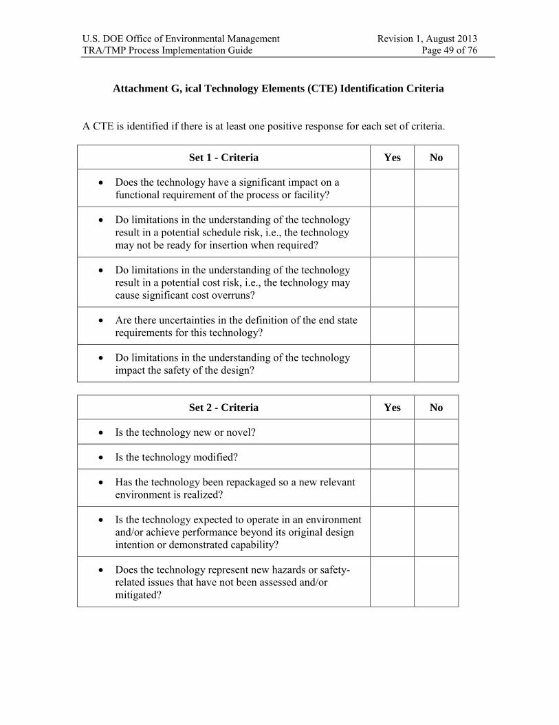
U.S. DOE Office of Environmental Management Revision 1, August 2013 TRA/TMP Process Implementation Guide Page 49 of 76
Attachment G, ical Technology Elements (CTE) Identification Criteria
A CTE is identified if there is at least one positive response for each set of criteria.
Set 1 - Criteria Yes No
Does the technology have a significant impact on afunctional requirement of the process or facility?
Do limitations in the understanding of the technologyresult in a potential schedule risk, i.e., the technologymay not be ready for insertion when required?
Do limitations in the understanding of the technologyresult in a potential cost risk, i.e., the technology maycause significant cost overruns?
Are there uncertainties in the definition of the end staterequirements for this technology?
Do limitations in the understanding of the technologyimpact the safety of the design?
Set 2 - Criteria Yes No
Is the technology new or novel?
Is the technology modified?
Has the technology been repackaged so a new relevantenvironment is realized?
Is the technology expected to operate in an environmentand/or achieve performance beyond its original designintention or demonstrated capability?
Does the technology represent new hazards or safety-related issues that have not been assessed and/ormitigated?

U.S. DOE Office of Environmental Management Revision 1, August 2013 TRA/TMP Process Implementation Guide Page 50 of 76
Attachment H, Technology Readiness Level Calculators

U.S. DOE Office of Environmental Management Revision 1, August 2013 TRA/TMP Process Implementation Guide Page 51 of 76
Attachment H, Technology Readiness Level Calculator
Table H1. Top Level Questions for Determining Anticipated TRL
Top-Level Question Yes/No If Yes, Then Basis and Supporting
Documentation
TRL 9
Has the actual equipment/process successfully operated in the full operational environment (hot operations)?
TRL 8
Has the actual equipment/process successfully operated in a limited operational environment (hot commissioning)?
TRL 7
Has the actual equipment/process successfully operated in the relevant operational environment (cold commissioning)?
TRL 6
Has engineering scale equipment/process testing been demonstrated in a relevant environment?
TRL 5
Has laboratory/bench scale equipment/process testing been demonstrated in a relevant environment?
TRL 4
Has laboratory/bench scale testing, at a minimum, of similar equipment systems been completed in a simulated environment? For some systems, such as mechanical systems, this may require full-scale prototype testing.
TRL 3
Has equipment and process analysis and proof of concept been demonstrated in a simulated environment?
TRL 2 Has an equipment and process concept been formulated?
TRL 1
Have the basic process technology process principles been observed and reported?

U.S. DOE Office of Environmental Management Revision 1, August 2013 TRA/TMP Process Implementation Guide Page 52 of 76
Attachment H, Technology Readiness Level Calculator (continued)
Table H.2. TRL 1 Questions for Critical Technology Element
T/P/M Y/N Criteria Basis and Supporting
Documentation
T 1. "Back of envelope"understanding of theenvironment.
T 2. Physical laws and assumptionsused in new technologiesdefined.
T 3. Paper studies confirm basicprinciples.
P 4. Initial scientific observationsreported in journals/conferenceproceedings/technical reports.
T 5. Basic scientific principlesobserved and understood.
P 6. Know who cares about thetechnology, e.g., sponsor,funding source, etc.
T 7. Research hypothesis formulated.T 8. Basic characterization data
exists.P 9. Know who would perform
research and where it would bedone.
T-Technology, technical aspects; M-Manufacturing and quality; P-Programmatic, customer focus, documentation

U.S. DOE Office of Environmental Management Revision 1, August 2013 TRA/TMP Process Implementation Guide Page 53 of 76
Attachment H, Technology Readiness Level Calculator (continued)
Table H.3. TRL 2 Questions for Critical Technology Elements
T/P/M Y/N Criteria Basis and Supporting Documentation
P 1. Customer identified and has expressedinterest, i.e., know what program thetechnology would support.
T 2. Potential system or components havebeen identified.
T 3. Paper studies show that application isfeasible; to include compliance withDOE Standard (STD) 1189-2008,Integration of Safety into the Design
Process.T 4. An apparent theoretical or empirical
design solution identified. T 5. Basic elements of technology have
been identified. T 6. Components of technology have been
partially characterized. T 7. Performance predictions made for each
element. T 8. Modeling & Simulation used to verify
physical principles. P 9. System architecture defined in terms of
major functions to be performed. T 10. Rigorous analytical studies confirm
basic principles. P 11. Analytical studies reported in scientific
journals/conference proceedings/ technical reports.
T 12. Individual parts of the technologywork.
T 13. Know what output devices areavailable.
P 14. Preliminary strategy to obtain TRL 6developed (e.g., scope, schedule, cost); to include compliance with DOE STD 1189-2008.
P 15. Know capabilities and limitations ofresearchers and research facilities.
T 16. The scope and scale of the wasteproblem has been determined.
T 17. Know what experiments are required(research approach).
P 18. Qualitative idea of risk areas (cost,schedule, performance).
T-Technology, technical aspects; M-Manufacturing and quality; P-Programmatic, customer focus, documentation

U.S. DOE Office of Environmental Management Revision 1, August 2013 TRA/TMP Process Implementation Guide Page 54 of 76
Attachment H, Technology Readiness Level Calculator (continued)
Table H.4. TRL 3 Questions for Critical Technology Elements
T/P/M Y/N Criteria Basis and Supporting Documentation
P 1. Some key process and safetyrequirements are identified; toinclude compliance with DOE STD1189-2008, Integration of Safety into
the Design Process.P 2. Key process parameters/variables
and associated hazards have begunto be identified; to includecompliance with DOE STD 1189-2008.
T 3. Predictions of elements oftechnology capability validated byanalytical studies.
P 4. The basic science has been validatedat the laboratory/bench scale.
T 5. Science known to extent thatmathematical and/or computermodels and simulations are possible.
P 6. Preliminary system performancecharacteristics and measures havebeen identified and estimated.
T 7. Predictions of elements oftechnology capability validated byModeling and Simulation (M&S).
M 8. Basic laboratory research equipmentto verify physical principles.
T 9. Predictions of elements oftechnology capability validated bylaboratory experiments.
P 10. Customer representative identified towork with development team.
P 11. Customer participates inrequirements generation.
P 12. Requirements tracking systemdefined to manage requirementscreep.
M 13. Design techniques have beenidentified/developed.
T 14. Paper studies indicate that systemcomponents ought to work together.
P 15. Customer identifies technology needdate.
T 16. Performance metrics for the systemare established (What must it do).
P 17. Scaling studies have been started.M 18. Current manufacturability concepts
assessed.

U.S. DOE Office of Environmental Management Revision 1, August 2013 TRA/TMP Process Implementation Guide Page 55 of 76
Table H.4. TRL 3 Questions for Critical Technology Elements
T/P/M Y/N Criteria Basis and Supporting Documentation
M 19. Sources of key components forlaboratory/bench testing identified.
T 20. Scientific feasibility fullydemonstrated.
T 21. Analysis of present state of the artshows that technology fills a need.
P 22. Risk areas identified in generalterms.
P 23. Risk mitigation strategies identified.P 24. Rudimentary best value analysis
performed for operations.T 25. Key physical and chemical
properties have been characterizedfor a number of waste samples.
T 26. A simulant has been developed thatapproximates key waste properties.
T 27. Laboratory/bench scale tests, at aminimum, on a simulant have beencompleted.
T 28. Specific waste(s) and waste site(s)has (have) been defined.
T 29. The individual system componentshave been tested at thelaboratory/bench scale, at aminimum. This may require full-scale prototype component testingfor some types of technologies, suchas mechanical systems.
T-Technology, technical aspects; M-Manufacturing and quality; P-Programmatic, customer focus, documentation
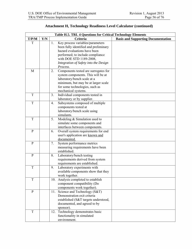
U.S. DOE Office of Environmental Management Revision 1, August 2013 TRA/TMP Process Implementation Guide Page 56 of 76
Attachment H, Technology Readiness Level Calculator (continued)
Table H.5. TRL 4 Questions for Critical Technology Elements
T/P/M Y/N Criteria Basis and Supporting Documentation
T 1. Key process variables/parametersbeen fully identified and preliminaryhazard evaluations have beenperformed; to include compliancewith DOE STD 1189-2008,Integration of Safety into the Design
Process.M 2. Components tested are surrogates for
system components. This will be atlaboratory/bench scale at aminimum, but may be at larger scalefor some technologies, such asmechanical systems.
T 3. Individual components tested inlaboratory or by supplier.
T 4. Subsystems composed of multiplecomponents tested atlaboratory/bench scale usingsimulants.
T 5. Modeling & Simulation used tosimulate some components andinterfaces between components.
P 6. Overall system requirements for enduser's application are known anddocumented.
P 7. System performance metricsmeasuring requirements have beenestablished.
P 8. Laboratory/bench testingrequirements derived from systemrequirements are established.
T 9. Laboratory experiments withavailable components show that theywork together.
T 10. Analysis completed to establishcomponent compatibility (Docomponents work together).
P 11. Science and Technology (S&T)Demonstration exit criteriaestablished (S&T targets understood,documented, and agreed to bysponsor).
T 12. Technology demonstrates basicfunctionality in simulatedenvironment.

U.S. DOE Office of Environmental Management Revision 1, August 2013 TRA/TMP Process Implementation Guide Page 57 of 76
Table H.5. TRL 4 Questions for Critical Technology Elements
T/P/M Y/N Criteria Basis and Supporting Documentation
M 13. Scalable technology prototypes havebeen produced (Can components bemade bigger than laboratory/benchscale).
P 14. Draft conceptual designs have beendocumented (system description,process flow diagrams, generalarrangement drawings, and materialbalance).
M 15. Equipment scale-up relationships areunderstood/accounted for intechnology development program.
T 16. Controlled laboratory environmentused in testing.
P 17. Initial cost drivers identified.M 18. Integration studies have been started.P 19. Formal risk management program
initiated.M 20. Key manufacturing processes for
equipment systems identified.P 21. Scaling documents and designs of
technology have been completed.P/T 22. Functional process description
developed. (Systems/subsystems identified).
T 23. Low fidelity technology “system”integration and engineeringcompleted in a laboratoryenvironment, at a minimum. Forsome technologies, such asmechanical systems, this may requirefull scale prototype testing.
T 24. Key physical and chemical propertieshave been characterized for a rangeof wastes.
T 25. A limited number of simulants havebeen developed that approximate therange of waste properties.
T 26. Laboratory/bench scale tests, at aminimum, on a limited range ofsimulants have been completed.
T 27. Process/parameter limits and safetycontrol strategies are being explored.
T 28. Test plan documents forlaboratory/bench, or appropriate,scale tests completed.
P 29. Technology availability datesestablished.
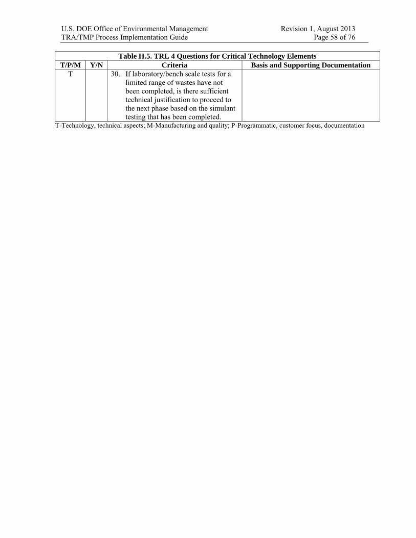
U.S. DOE Office of Environmental Management Revision 1, August 2013 TRA/TMP Process Implementation Guide Page 58 of 76
Table H.5. TRL 4 Questions for Critical Technology Elements
T/P/M Y/N Criteria Basis and Supporting Documentation
T 30. If laboratory/bench scale tests for alimited range of wastes have notbeen completed, is there sufficienttechnical justification to proceed tothe next phase based on the simulanttesting that has been completed.
T-Technology, technical aspects; M-Manufacturing and quality; P-Programmatic, customer focus, documentation

U.S. DOE Office of Environmental Management Revision 1, August 2013 TRA/TMP Process Implementation Guide Page 59 of 76
Attachment H, Technology Readiness Level Calculator (continued)
Table H.6. TRL 5 Questions for Critical Technology Elements
T/P/M Y/N Criteria Basis and Supporting Documentation
T 1. The relationships between majorsystem and sub-system parametersare understood on a laboratory/benchscale.
T 2. Plant size components available fortesting.
T 3. System interface requirementsknown. (How would system beintegrated into the plant?)
P 4. Preliminary design engineering hasbegun
T 5. Requirements for technologyverification established, to includetesting and validation of safetyfunctions.
T 6. Interfaces betweencomponents/subsystems in testingare realistic (bench top with realisticinterfaces).
M 7. Prototypes of equipment systemcomponents have been created (knowhow to make equipment).
M 8. Manufacturing techniques have beendefined to the point where largestproblems defined.
M 9. Availability and reliability (RAMI)target levels identified.
T 10. Laboratory environment for testingmodified to approximate operationalenvironment; to include testing andvalidation of safety functions.
T 11. Component integration issues andrequirements identified.
P 12. Detailed 3D design drawings andP&IDs have been completed tosupport specification of anengineering-scale testing system.
T 13. Requirements definition withperformance thresholds andobjectives established for final plantdesign.
P 14. Preliminary technology feasibilityengineering report completed; toinclude compliance with DOE STD1189-2008, Integration of Safety into
the Design Process.
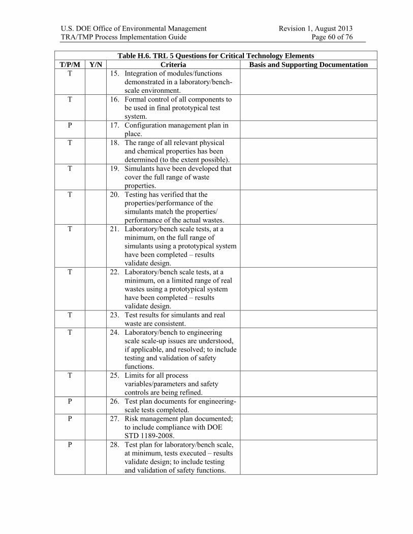
U.S. DOE Office of Environmental Management Revision 1, August 2013 TRA/TMP Process Implementation Guide Page 60 of 76
Table H.6. TRL 5 Questions for Critical Technology Elements
T/P/M Y/N Criteria Basis and Supporting Documentation
T 15. Integration of modules/functionsdemonstrated in a laboratory/bench-scale environment.
T 16. Formal control of all components tobe used in final prototypical testsystem.
P 17. Configuration management plan inplace.
T 18. The range of all relevant physicaland chemical properties has beendetermined (to the extent possible).
T 19. Simulants have been developed thatcover the full range of wasteproperties.
T 20. Testing has verified that theproperties/performance of thesimulants match the properties/performance of the actual wastes.
T 21. Laboratory/bench scale tests, at aminimum, on the full range ofsimulants using a prototypical systemhave been completed – resultsvalidate design.
T 22. Laboratory/bench scale tests, at aminimum, on a limited range of realwastes using a prototypical systemhave been completed – resultsvalidate design.
T 23. Test results for simulants and realwaste are consistent.
T 24. Laboratory/bench to engineeringscale scale-up issues are understood,if applicable, and resolved; to includetesting and validation of safetyfunctions.
T 25. Limits for all processvariables/parameters and safetycontrols are being refined.
P 26. Test plan documents for engineering-scale tests completed.
P 27. Risk management plan documented;to include compliance with DOESTD 1189-2008.
P 28. Test plan for laboratory/bench scale,at minimum, tests executed – resultsvalidate design; to include testingand validation of safety functions.

U.S. DOE Office of Environmental Management Revision 1, August 2013 TRA/TMP Process Implementation Guide Page 61 of 76
Table H.6. TRL 5 Questions for Critical Technology Elements
T/P/M Y/N Criteria Basis and Supporting Documentation
P 29. Finalization of hazardous materialforms and inventories, completion ofprocess hazard analysis, andidentification of system/componentslevel safety controls at theappropriate preliminary designphase.
T-Technology, technical aspects; M-Manufacturing and quality; P-Programmatic, customer focus, documentation

U.S. DOE Office of Environmental Management Revision 1, August 2013 TRA/TMP Process Implementation Guide Page 62 of 76
Attachment H, Technology Readiness Level Calculator (continued)
Table H.7. TRL 6 Questions for Critical Technology Elements
T/P/M Y/N Criteria Basis and Supporting Documentation
T 1. The relationships between system andsub-system parameters are understood atengineering scale allowing process/designvariations and tradeoffs to be evaluated.
M 2. Availability and reliability (RAMI) levelsestablished.
P 3. Preliminary design drawings for finalplant system are complete; to includecompliance with DOE STD 1189-2008,Integration of Safety into the Design
Process.
T 4. Operating environment for final systemknown.
P 5. Collection of actual maintainability,reliability, and supportability data hasbeen started.
P 6. Performance Baseline (including totalproject cost, schedule, and scope) hasbeen completed.
T 7. Operating limits for componentsdetermined (from design, safety andenvironmental compliance).
P 8. Operational requirements documentavailable; to include compliance withDOE STD 1189-2008.
P 9. Off-normal operating responsesdetermined for engineering scale system.
T 10. System technical interfaces defined.T 11. Component integration demonstrated at an
engineering scale, at a minimum. Mayinclude full-scale prototype for sometechnologies, such as mechanical systems.
P 12. Analysis of project timing ensurestechnology will be available whenrequired
P 13. Have established an interface controlprocess.
P 14. Acquisition program milestonesestablished for start of final design (CD-2).
M 15. Critical manufacturing processesprototyped.
M 16. Most pre-production hardware is availableto support fabrication of the system.
T 17. Engineering feasibility fullydemonstrated.

U.S. DOE Office of Environmental Management Revision 1, August 2013 TRA/TMP Process Implementation Guide Page 63 of 76
Table H.7. TRL 6 Questions for Critical Technology Elements
T/P/M Y/N Criteria Basis and Supporting Documentation
M 18. Materials, process, design, and integrationmethods have been employed (e.g., candesign be produced?)
P 19. Technology “system” design specificationcomplete and ready for detailed design.
T 20. Engineering-scale system is high-fidelityfunctional prototype of operationalsystem.
P 21. Formal configuration managementprogram defined to control changeprocess.
P 22. Final technical report on technologycompleted; to include compliance withDOE STD 1189-2008. Report is asummary of technology developmentactivities.
M 23. Process and tooling are mature to supportfabrication of components/system.
T 24. Engineering-scale tests, at a minimum, onthe full range of simulants using aprototypical system have been completed– results validate design.
T 25. Engineering to full-scale scale-up issuesare understood and resolved.
T 26. Test results are consistent forlaboratory/bench and engineering-scaleexperiments, and/or prototype testing asapplicable.
M 27. Production demonstrations are complete(at least one time).
P 28. Integration demonstrations of the CTEhave been completed (e.g., construction oftesting system); to include testing andvalidation of safety functions.
P 29. Finalization of hazardous material formsand inventories; completion of processhazard analysis, identification ofsystem/components level safety controlsat the appropriate preliminary/final designphase.
T-Technology, technical aspects; M-Manufacturing and quality; P-Programmatic, customer focus, documentation

U.S. DOE Office of Environmental Management Revision 1, August 2013 TRA/TMP Process Implementation Guide Page 64 of 76
Waste Processing System Technology Readiness Level Calculators, TRL 4 and TRL 6, for assessing system integration.
Table H.8. TRL 4 Questions for Waste Processing System (WPS)
CTE:
Y/N Questions Basis and Supporting
Documents
Processing 1. Is the WPS, as it appears in the conceptualdesign, intended to accept the full range ofwastes to be processed?
2. Is the WPS capable of meeting targets forstartup and completion of waste processing?
3. Have the target operational and performancerequirements for the WPS been determined?
4. Have all technology elements (TEs) that requirean increase or change in capability beenidentified as CTEs?
5. Has WPS process flow been modeled?6. Have WPS single point failures been identified?7. Can TEs be sized to meet WPS throughput
requirements?8. Have all new or novel operating modes of the
WPS been modeled and/or tested atlaboratory/bench scale?
9. Have all recycle streams been identified andincluded in the conceptual design process flowmodels?
10. Have the key safety aspects of the WPS relatedto processing been identified?
11. Are appropriate measures in place to ensure safeoperation of the processing activities?
Disposal 12. Will the WPS produce a product or productsthat meet disposal path requirements?
13. Are all WPS waste streams identified andcharacterized to the extent necessary forconceptual design?
14. Can all WPS waste streams, including, processliquids, off gases, and solids identified in theconceptual design be treated and disposed
15. Will the waste streams meet the wasteacceptance criteria of the proposed dispositionfacilities/sites?
16. Have the disposition facilities/site beencontacted to ensure that the waste forms arecompatible with facility/site operations,
procedures, and regulations?17. Have the key safety aspects of the WPS related
to disposal been identified?18. Are appropriate measures in place to ensure safe
operation of the disposal activities?Interfaces 19. New or novel interfaces among WPS systems
have been identified as CTEs?

U.S. DOE Office of Environmental Management Revision 1, August 2013 TRA/TMP Process Implementation Guide Page 65 of 76
Table H.8. TRL 4 Questions for Waste Processing System (WPS)
CTE:
Y/N Questions Basis and Supporting
Documents
20. Are all WPS technology interfaces anddependencies determined and understood at theconceptual level?
21. Can all WPS components be successfullymated?
22. Are the processing modes of the TEs (e.g.,batch, continuous) compatible?
23. Have the key safety aspects of the WPS relatedto disposal been identified?
24. Are appropriate measures in place to ensure safeoperation of the disposal activities?

U.S. DOE Office of Environmental Management Revision 1, August 2013 TRA/TMP Process Implementation Guide Page 66 of 76
Table H.9. TRL 6 Questions for the Waste Processing System (WPS)
CTE:
Y/N Questions Basis and Supporting
Documents
Processing 1. Have all TEs that require an increase or changein capability been identified as CTEs?
2. Can the WPS accept the full range of wastes tobe processed?
3. Is the WPS capable of meeting targets forstartup and completion of waste processing?
4. Have the target operational and performancerequirements for the WPS been determined?
5. Have major sections of the WPS and theirinterfaces been modeled and/or tested?
6. Has WPS data collection and data flow beenmodeled/tested?
7. Has WPS process flow and process control beenmodeled/tested?
8. Have WPS CTE single point failures (processand safety) been identified?
9. Can TEs be sized to meet WPS throughputrequirements?
10. Have all new or novel operating modes of theWPS been modeled and/or tested?
11. Are all recycle and secondary streams fullycharacterized?
12. Are all recycle and secondary streams includedin process models?
13. Have the key safety aspects of the WPS relatedto processing been identified?
14. Are appropriate measures in place to ensure safeoperation of the processing activities?
15. Is the appropriate documentation in place thatadequately describes the safety features relatedto processing, and their functions in the overallintegrated WPS?
Disposal 16. Will the WPS produce a product or productsthat meet disposal path requirements?
17. Are all WPS waste streams identified?18. Have the waste streams produced by the WPS
been fully characterized?19. Has a disposition path been determined for each
waste stream, including, process liquids, offgases, and solids?
20. Will the waste forms meet the waste acceptancecriteria of the proposed disposition facilities?
21. Have the disposition facilities/sites beencontacted to ensure that the waste streams arecompatible with disposal facility/siteoperations, procedures, and regulations?

U.S. DOE Office of Environmental Management Revision 1, August 2013 TRA/TMP Process Implementation Guide Page 67 of 76
Table H.9. TRL 6 Questions for the Waste Processing System (WPS)
CTE:
Y/N Questions Basis and Supporting
Documents
22. Have the key safety aspects of the WPS relatedto disposal been identified?
23. Are appropriate measures in place to ensure safeoperation of the disposal activities?
24. Is the appropriate documentation in place thatadequately describes the safety features relatedto disposal, and their functions in the overallintegrated WPS?
Interfaces 25. Are all WPS technology interfaces anddependencies determined and understood?
26. New or novel interfaces among WPS systemshave been identified as CTEs?
27. Have all WPS TE interfaces been modeled ortested?
28. Are the processing modes of the TEs (e.g.,batch, continuous) compatible?
29. Have the key safety aspects of the WPS relatedto disposal been identified?
30. Are appropriate measures in place to ensure safeoperation of the disposal activities?
31. Is the appropriate documentation in place thatadequately describes the safety features relatedto disposal, and their functions in the overallintegrated WPS?

U.S. DOE Office of Environmental Management Revision 1, August 2013 TRA/TMP Process Implementation Guide Page 68 of 76
7.0 APPENDICES
Appendix 1, TRL 7 (Working Draft) Appendix 2, Software TRA (Working Draft)
These appendices are working drafts. They are published here for information. Teams may use this information as they deem appropriate. Comments on this information should be sent to the EM CPOT. After these guides are piloted during appropriate technology assessments, they will be updated and fully incorporated in the guide.

U.S. DOE Office of Environmental Management Revision 1, August 2013 TRA/TMP Process Implementation Guide (Working Draft) Appendix 1, TRL 7 Calculator Page 69 of 76
Appendix 1, TRL 7 Calculator
Working Draft
Integration of Technology and Operational Readiness
Over the past years, DOE has implemented several initiatives to improve performance in technical, safety and project execution. These initiatives have resulted in a number of requirements and guidance that need to be addressed as a project moves towards completion. These requirements and guidance are documented in several documents and they include:
DOE-O-425.1D, Verification of Readiness to Startup or Restart Nuclear Facilities –when coupled with DOE-STD-3006-2010, Planning and Conducting Readiness
Reviews, provides requirements and guidance on how to meet the requirements forevaluating the operational readiness of new or modified nuclear facilities prior tostartup (or restart).
DOE-G-413.3-4A, Technology Readiness Assessment Guide – which providesdescriptive information for later Technology Readiness Levels (TRL 7 through 9), butdoes not provide examples of detailed criteria for assessing whether these TRL’s havebeen achieved.
DOE-G-413.3-16A, Project Completion/Closeout Guide – which chronicles the latterstages of project management, and provides some top-level discussion of theintegration of operational and technology readiness on a project.
Taken individually, these DOE documents could be viewed to involve an excessive number of assessments or reviews and reports during the latter stages of a project; for example:
DOE-O-425.1D and DOE-STD-3006-2010 – involve a Startup Notification Report(SNR) issued for projects at least one year prior to startup; a Plan of Action (POA)that provides detailed planning information to implement the requirements of DOE-O-425.1D for a specific project, including the breadth and depth anticipated for thereview and identification of the readiness review team leader (this must be completedno later than 6 months prior to the startup); the readiness review leader identified bythe POA then works with his selected review team to develop the detailed Lines ofInquiry (LOIs) that will be used to evaluate operational readiness (which includes atechnical review of the process) and, with the team membership and review schedule,make up the major parts of the Implementation Plan for readiness review; as part ofthe readiness review, the team is required to review the project/facility Startup Planfor adequacy and the readiness of both process and safety systems to supportoperations.
DOE-G-413.3-4A – describes that “detailed” Test Plans are needed to implement theTMPs, which are required when the TRL determined during TRA’s at CD-1 and/or 2to not meet expected levels. The results of the detailed test plans are to be “closedout” with Technical Reports.

U.S. DOE Office of Environmental Management Revision 1, August 2013 TRA/TMP Process Implementation Guide (Working Draft) Appendix 1, TRL 7 Calculator Page 70 of 76
DOE-G-413.3-16A – lists a number of plans and reports recommended at the end ofthe project life-cycle, they include: (a) Checkout, Testing and Commissioning Plan,(b) Transition to Operations Plan, (c) Project Acceptance Checklists, (d) ProjectCloseout Process (to be documented in the Project Execution Plan), and(e) Inspection and Acceptance Report.
Potential Integration of TRA/TMP into Readiness and Closure Evolutions:
Readiness Review Planning – can use the TMP as one of its references and completion of the actions associated with the TMP, along with the Test Reports, could be a candidate for a pre-requisite for the DOE readiness review. The TMP and Test Reports can also be used as references in the LOIs that guide the assessments done during the readiness review. If the TRA is meant to evaluate whether TRL 7A has been achieved, this should be reflected in the POA and Implementation Plan for the readiness review; if desired, this will likely impact the selection of readiness review team members. Format and content expectations for the Project Acceptance Checklists and Inspection and Acceptance Report may also be reviewed as part of readiness review planning, if integration of this effort is also planned by the Project Execution Plan and POA for the readiness review. Finally, preparation and integration planning by the Integrated Project Team (IPT) can ensure that the expectations and requirements for the Startup Test Plan, required as part of the readiness review process, meets many of the expectations of the Checkout, Testing and Commissioning Plan and Transition to Operations Plan.
Readiness Review Execution – the detailed technical reviews performed during the readiness review can serve as verification of technical adequacy of systems for both TRL and Project Closure purposes, if properly planned and documented. For ease of use, the attached Draft TRL calculator, Table A1.1, has been developed to integrate readiness review, TRL determination and several Project Closure documents. For ease of integration with the readiness review process, criteria in the attached TRL determination checklist have been split into TRL 7A for items expected to be completed before the start of the DOE readiness review and TRL 7B for those items that can only be completed after the Startup Test Plan and Transition to Operations have been completed.

U.S. DOE Office of Environmental Management Revision 1, August 2013 TRA/TMP Process Implementation Guide (Working Draft) Appendix 1, TRL 7 Calculator Page 71 of 76
Table A1.1. TRL 7 Questions for Critical Technology Elements
T/P/M Y/N Criteria Basis and Supporting
Documentation
T 1. The relationships between system and sub-systems at full scale are understood. [7A]
M 2. Reliability, availability, maintainability,and inspectability (RAMI) analysiscompleted; data available for use inengineering and safety analysis. [7A]
T 3. Test results from full-scale testinganalyzed for differences between testingenvironment and operating environment;any inconsistencies are documented andstrategies to resolve them duringcommissioning are defined. [7B]
P 4. Design drawings, including as-built information, are consistent with the requirements for Final Design; Final Design information incorporated in PDSA & Technical Safety Requirements (TSR). [7A]
P 5. Performance Baseline has been updated based on the final design and construction information, as required. [7A]
T 6. Operating limits (including processvariables and parameters) for sub-systemsand components verified by testing inrelevant environment at the largest scalepracticable. [7A]
P 7. Operational requirements documentreflects final design and “as-built”information. [7B]
T 8. Off-normal operating responses have beendemonstrated during full-scale testing.[7B]
T 9. Full-scale testing, verifies systemtechnical interfaces. [7B]
T 10. Sub-system integration has beendemonstrated at the largest scalepracticable. [7A]
P 11. Scaling issues have been resolved bytesting, physical modeling or analysis.[7A]
P 12. Interface control process updated to reflectFinal Design and “as-built” information.[7A]
P 13. Acquisition program milestones have beenestablished through Transition toOperations. [7A]

U.S. DOE Office of Environmental Management Revision 1, August 2013 TRA/TMP Process Implementation Guide (Working Draft) Appendix 1, TRL 7 Calculator Page 72 of 76
Table A1.1. TRL 7 Questions for Critical Technology Elements
T/P/M Y/N Criteria Basis and Supporting
Documentation
M 14. Manufacturer’s testing and anyprocess/production demonstrationscompleted and documented; anyinconsistencies are documented andstrategies to resolve them duringcommissioning are defined. [7A]
M/T 15. System constructed and operationalfeasibility has been demonstrated throughdemonstration of systems or sub-systemsin a relevant environment at the largestscale practicable. [7A]
P 16. Technology incorporated into applicablesystem design descriptions (technical andfunctional). [7A]
T 17. Sub-systems verified to be compatiblewith operating systems, as applicable.[7A]
T 18. Prototypical system(s) used for sub-systemintegration testing (prior to Startup Testprogram) is similar to the operationalsystem. [7A]
P 19. Formal configuration managementprogram is documented and implemented.[7A]
M/T 20. Integration of sub-systems has beenverified. [7A]
P 21. Checkout, Testing and CommissioningPlan (DOE-G-413.3-16A) and StartupPlan (DOE-O-425.1D) are complete andintegrated. [7A]
22. Checkout, Testing and CommissioningPlan and Startup Plan adequately plan theconfirmation of system operability throughHot Operations. [7A]
P/T 23. Startup Testing integrates demonstrationof safety-related requirements DSA-andTSR, in compliance with DOE STD-1189-2008. [7A]
P 24. DSA and TSRs are approved. [7A]
T 25. Prototypical full-scale testing with a rangeof simulants is complete and testdeficiencies have been documented andresolutions developed. [7B]

U.S. DOE Office of Environmental Management Revision 1, August 2013 TRA/TMP Process Implementation Guide (Working Draft) Appendix 1, TRL 7 Calculator Page 73 of 76
Table A1.1. TRL 7 Questions for Critical Technology Elements
T/P/M Y/N Criteria Basis and Supporting
Documentation
T 26. Prototypical full-scale test results havebeen compared to laboratory andengineering-scale testing, including realwaste tests, and results are consistent orinconsistencies analyzed and resolved.[7A]
T 27. Limits for process variables andparameters and safety controls have beendocumented and included in applicabletests and operating procedures. [7A]
M 28. Special tooling or procedures foroperations or maintenance have beendeveloped and demonstrated. [7A]
P 29. Quality assurance documentation forsystems is complete, incorporating FinalDesign and as-built information. [7A]
T/P 30. All resulting wastes requiring dispositionhave been identified and verified throughintegrated testing at the largest scalepracticable for compatibility with storage,transportation and disposal facilityrequirements. [7A]
T 31. A fully integrated system has beensuccessfully operated at full scale in therelevant environment. Target operational,performance and safety requirements havebeen verified. [7B]

U.S. DOE Office of Environmental Management Revision 1, August 2013 TRA/TMP Process Implementation Guide (Working Draft) Appendix 2, Process Control System TRA Page 74 of 76
Appendix 2, TRA Guidance for Evaluating Process Control Systems and
Process-Related Software Development
Working Draft
The guidance provided in this appendix for the conduct of a TRA of a process control system and process-related software is based upon information contained in the DoD TRA guidance5
and recommendations from the Air Force Research Laboratory on the conduct of software TRAs6. This EM Guide includes a TRL calculator for TRL 6. The questions in the TRL calculator have evolved through use on several previous TRAs within DOE-EM7.
The identification of CTEs for process control systems and process-related software is dependent on the system type and complexity. A single CTE could be used if the process control system is relatively simple, and little software is used in the system.
Points to consider when conducting a TRA of a process control system and process-related software include:
This TRL calculator is based on achieving a TRL 6 at CD-2 or the project/programequivalent. Thus, in adjusting the calculator questions to a specific project terms suchas “Preliminary Design” may need to be revised to what is expected for thatproject/program or stage in development.
The TRL 6 calculator questions are intended to address both process control systemsand process-related software. However, for complex process control systems, whichmay include a number of subsystems or a tiered architecture, an approach thatevaluates appropriate sub-systems as CTEs, along with an integrated view of thesystem TRL determination may be appropriate. In the case of complex systems,tailoring of the attached TRL calculator is encouraged.
The use and control of manufacturer-provided software for component configurationpurposes is included.
Completion of the TRL 6 evaluation for process control system and process-relatedsoftware shares a number of attributes with completion of the TRL calculator for“Waste Processing Systems.” The WPS TRL calculators can be found inAttachment H, Tables H.8 and H.9. There are several areas of potential overlapbetween these two new tools (e.g., “integrated testing”) and TRA Teams performingboth reviews are encouraged to integrate these efforts.
5 U.S. Department of Defense (DoD), “Technology Readiness Assessment (TRA) Guidance,” April 2011; and “TechnologyReadiness Assessment (TRA) Deskbook,” July 2009. 6 Air Force Smart Operations-21, “Software Technology Readiness Assessment Recommendations,” April 30,2009. 7 These have included TRAs of the software and control systems associated with the Low-Activity Waste Facility, the Laboratory, and Balance of Plant facilities at the Hanford Waste Treatment Plant (WTP), and a TRA of the Hanford K Basins Sludge Treatment Project.

U.S. DOE Office of Environmental Management Revision 1, August 2013 TRA/TMP Process Implementation Guide (Working Draft) Appendix 2, Process Control System TRA Page 75 of 76
Process Control/Software System – TRL 6
Table A2.1. TRL 6 Questions for Process Control System and Process-Related Software
CTE:
Item # Y/N Questions Basis and Supporting
Documents
1. System/subsystem process/mechanical preliminary design and integration with any existing systems completed?
2. Preliminary System Descriptions are completed and approved?
3. Preliminary system P&IDs are approved? 4. Preliminary process control strategy is
documented, including: operator actions/control, automatic control, and the integration of operator actions and automatic control, and data acquisition/management?
5. System functional requirements are documented?
6. System process control/software architecture and logic are established?
7. Operating environment definition finalized?
8. Have test requirements been specified to verify the proper use and function of: process controls; process-related software, including manufacturer-provided software used to configure relays, component controls and sensors; and integration with any existing control systems?
9. Process system process control/software has been formally placed under configuration control.
10. Process system controls and process control software is complete to support preliminary design.
11. Has the proper use and function of manufacturer-provided software, used to configure relays, component controls and sensors, been confirmed through system design reviews and system testing?

U.S. DOE Office of Environmental Management Revision 1, August 2013 TRA/TMP Process Implementation Guide (Working Draft) Appendix 2, Process Control System TRA Page 76 of 76
Table A2.1. TRL 6 Questions for Process Control System and Process-Related Software
CTE:
Item # Y/N Questions Basis and Supporting
Documents
12. Have impacts of the process control strategy (equipment, software, operator actions) on reliability, availability, maintainability, and inspectability—including the avoidance of single-point failures—been evaluated and documented?
13. Process system controls, process control software system, and process control strategy demonstrated at range of anticipated normal and off-normal conditions simulated process operations.
14. Validated and verified process control/software test exception/test discrepancies have been documented and resolved for normal and off normal simulated process operating conditions.
15. Has the process control strategy been verified for subsystem operational integration?
16. Equipment component and system set point ranges have been established.
17. Does the preliminary design address the integration of normal process control/software and safety process control/software?