rlc advance training - cloudinary
TRANSCRIPT

11/6/2020
1
RLC Advance Training
Rev 2.5
RLC Advance Service TrainingDue to Samsung’s policy of ongoing product development, specifications are subject to change without prior notice. Every effort has been made to insure that the information included in this presentation is as accurate as possible at the time of it’s publication.
This presentation is provided as a guide to help HVAC field technicians understand the most common service and diagnostic procedures for the Samsung RLC systems. This training module is not intended to replace Samsung service manuals, technical data books, installation/operation manuals or other factory documents.
Only properly trained, HVAC professionals should attempt to install and start up any Samsung heating and air-conditioning system.
High Voltage Caution:Extra care must be taken when working on or around RLC equipment due to numerous high voltage components. Whether installing or servicing RLC systems in the field or while attending Samsung HVAC training classes which include powered simulators and equipment, be aware of the potential dangers of high voltage – use caution
This presentation may only be used with authorization by Samsung HVAC. Unauthorized use, duplication or alteration of this presentation is prohibited.
For technical support issues, always contact your Samsung equipment provider.
www.samsunghvac.com www.dvmdownload.com2
1
2
11/6/2020
2
RLC Advance Training
Contents
RLC Product Line
Basic Component Acronyms
Basic System Components
Wireless Remote Controller Basic Features
Basic System Operation Logic & Control
Basic System Troubleshooting
Troubleshooting Error Codes
3
3
4

11/6/2020
3
Samsung Business Academy (SBA)
• SamSBA Account Sign Up Required:
• Register for future training classes/courses.• Receive credit for this training class.• Access completion certificates.• Complete surveys/submit feedback.
Samsung Business Academy (SBA)
• Sam1. Sign up for a SBA Account
• Contractor • Distributor
2. View/print completion certificates3. Register for future training
• Instructor-Led Courses• Online Demand
5
6

11/6/2020
4
Go to: www.samsunghvac.com*
Hover over:
Choose either:
1. Sign Up for a SBA Account
Samsung Business Academy Registration
HVAC DistributorHVAC Contractor
*Disable popup blocker.
HVAC Contractor1. Sign Up for a SBA Account
Complete all required fields designated by an asterisk (*).
.
Click partner to add Distributor
information.
Distributor Name1
My Distributor
Type Distributor Name Click Search2
3 Click your Distributors name to add to form.
My Distributor
YOUR DISTRIBUTOR
If your Distributor is not in the list, Type Other in the ID: field. 1
2
3
Click Search
Click OTHER to add to form.
7
8

11/6/2020
5
Complete the rest of the Sign Up form.
Select “Opt-In” to receive training communications.4
1. Sign Up for a SBA Account
5 Create password using required format.
6Click Submit to complete sign-up.
01 Approval takes 1-2 business days.
02Attendance ismarked complete.
03 Certificate available in SBA.
After account is setup…
1. Sign Up for a SBA Account
Complete all required fields designated by an asterisk (*).
.
Click partner to add Distributor
information.
Distributor Name1
My Distributor
Type your Business Name Click Search2
3 Click your Business name to add to form.
My Distributor
DISTRIBUTOR NAME
If your Business is not in the list, Type Other in the ID: field. 1
2
3
Click Search
Click OTHER to add to form.
HVAC Distributor
9
10

11/6/2020
6
Complete the rest of the Sign Up form.
Select “Opt-In” to receive training communications.4
1. Sign Up for a SBA Account
5 Create password using required format.
6Click Submit to complete sign-up.
01 Approval takes 1-2 business days.
02Attendance ismarked complete.
03 Certificate available in SBA.
After account is setup…
2. View/Print Completion CertificatesGo to www. https://samsunghvac.com/our_training.php
Click:
1
23 Open Menu. ( )
4 Click “View Your Transcript”.
Login with Samsung Business Academy (SBA) username/password.
11
12

11/6/2020
7
2. View/Print Completion Certificates4 Click “View Completion Page”.
5 Click “View My Certificate”.
6 Select “Print” or “Save” option(s).
Note: Confirmation email will be sent with link to down-load certificate.
3. Register for Future TrainingGo to www. https://samsunghvac.com/our_training.php
Click:
1
23 Samsung Business Academy (SBA) displays.
• Hover - on class name to view class information.• Click - on class name to open the class
registration form.
Login with Samsung Business Academy (SBA) username/password.
Instructor - Led Training
13
14

11/6/2020
8
3. Register for Future Training
Click “Request”.4
Registration status screen displays.
5 Confirmation email will be sent.
Note: If you do not receive with email within 15 minutes, check your Junk/Spam folder. Add *@samsunghvac.com to trusted sites.
3. Register for Future Training
1 Open Menu. ( )
2 Click “Browse for Training”.
On - Demand Training
3 Click “Browse All”. 4 Click “Type”*.
5 Select course and click “Launch”.
*Online, Video and Materials.
15
16

11/6/2020
9
RLC Product Line
Pearl, Whisper & Wind Free Smart Pearl: 9,000 & 12,000 Btu/h models SEER: up to 28 WiFi control standard
Smart Whisper – MAX Heat: 9,000 to 24,000 Btu/h models SEER: up to 23 WiFi control standard
Wind Free: 9,000 & 12,000 Btu/h Models SEER: up to 21 WiFi control standard
Quantum 9,000 Btu to 24,000 Btu models SEER: 17 Not WiFi compatible
MAX 36,000 Btu/h model SEER: 18 Not WiFi compatible
Single Zone RAC Systems
18
17
18

11/6/2020
10
RLC Product LineMulti-zone Zone FJM Systems
Whisper Wallmount
Mini 4-Way Cassette
Slim Duct
AJ020JCJ2CH 2-port AJ024JCJ3CH 3-port
AJ036JCJ5CH 5-port AJ020MCS3CH 3-port AJ024MCS4CH 4-port AJ030MCS4CH 4-port
MAX Heat
19
RLC Advance ServiceBasic Component Acronyms
BLDC – Brushless Digitally Commutated, referring to the Samsung inverter rotary compressor and fan motors EEPROM – Electrically Erasable Programmable read-only non-volatile Memory device used to store data information to control
another device. Data can be erased and reflashed (programmed) with new control data EEV – Electronic Expansion Valve is a digitally pulsed, motor (coil) driven expansion valve regulating the flow of refrigerant
through a heat exchanger coil EMI – Line voltage filter IDU – Indoor Unit IGBT – Insulated-gate Bipolar Transistor (Inverter component) INV – Refers to prefix for Inverter PCB or inverter compressor (inverter driven compressor) IPM – Intelligent Power Module MCA – Minimum Circuit Amps MFA – Maximum Fuse Amps ODU – Outdoor Unit OLP – Overload Prevention PCB – Printed circuit board (also PBA) PFC – Power Factor Correction (Refers to a capacitor) SMPS – Switched Mode Power Supply (IDU & ODU) – Rectifier: converts ac voltage to dc voltage
20
19
20

11/6/2020
11
RLC Advance Service
Basic System Components
21
Basic System ComponentsBasic Inverter Technology
The Inverter Is: A variable frequency drive (VFD) that changes the electrical frequency (hertz) applied to an electric motor to control the motor speed (RPM)
up and down The inverter technology is used to vary the HVAC system’s operating capacity to match the heating and cooling load as it changes
The inverter drive controls the compressor speed like an automobile’s throttle controls engine speed The inverter varies the applied frequency to the compressor based on a number of system temperature sensors (thermistors) and the room
setpoint temperature selected on the remote controller
The advantages of inverter control as compared to standard on/off Higher system efficiency (Part-load efficiency) More accurate space temperature control
22
21
22

11/6/2020
12
Basic System ComponentsBasic Inverter Technology
Pulsating 3 Phase AC OUTPUT
INPUT AC Line Voltage
T(sec)
+V
-V60 Hz
T(sec)
+V
-V Variable Frequency (Hz)
Samsung Inverter Controller
DC Volts
The Samsung inverter controller converts the incoming ac line voltage to dc voltage (rectifier)
This dc voltage is then fed to the Intelligent Power Module (IPM) The dc voltage is then run through a set of Insulated Gate Bipolar Transistors (IGBT)
which are electronic switches that allow the dc voltage output to simulate 3-phase ac voltage
The resulting variable pulsating “ac” voltage and frequency (Hertz) can be controlled by the rate at which the IGBT’s switch
23
Basic System ComponentsSamsung BLDC Rotary Compressor
Single and Twin rotary models Higher Reliability & Durability Higher Efficiency Small physical size for Btu/h output capacity Reserve Capacity Neodymium Permanent Magnets
Twin rotary example
24
23
24

11/6/2020
13
Basic System ComponentsSamsung Anti Corrosion Fin Coating
The indoor and outdoor unit heat exchanger’s aluminum fins are coated with a hydrophilic protective coating Reduced coil corrosion Promotes water shedding for better condensate flow, easier coil cleaning and faster defrost cycles
Samsung’s Coated Indoor Coil
25
Basic System ComponentsOutdoor Unit Micro Channel Heat Exchanger - DuraFin
Standard Aluminum Fin / Copper Tube Aluminum Micro channel condenser coil
Higher heat transfer efficiency 5 times larger heat transfer area 17% reduction in air flow friction Higher airflow at the same fan speed
Smart Pearl CAC26
25
26

11/6/2020
14
Basic System ComponentsOutdoor Unit Micro Channel Heat Exchanger - DuraFin
Standard Aluminum Fin / Copper Tube Aluminum Micro channel condenser coil
Small heat transfer surface area 5 times larger heat transfer surface area
High air flow friction Low air flow friction
27
Basic System Components Outdoor Unit Micro Channel Heat Exchanger - DuraFin
Better anti-corrosion coating Corrosion resistance more than 3 times greater than our conventional PFC corrosion protection Tested over 90 days with no leakage at 595 psi using the Sea Water Acetic Acid Test Samsung DuraFin Micro Channel outdoor heat exchangers are featured exclusively on
Smart Pearl and CAC product lines 28
27
28

11/6/2020
15
Basic System ComponentsRLC Electronic Expansion Valve
Electronic Expansion Valve (EEV) Components: Stepper motor – Valve body – Control algorithm
The “stepper motor” is an electro-magnetic coil assembly that can divide a full rotation into a large number of steps (480 steps), designated as “pulses” Primary characteristics is its ability to rotate a prescribed angle (steps) in response to each control pulse applied to the coil in each direction
The electronic expansion valve is the component that controls the rate at which liquid refrigerant can flow into the evaporator coil (superheat) RLC systems incorporate the indoor coil EEV in the outdoor unit
Control algorithm is continuously providing signals to the EEV to open or close by small amounts (pulses) to vary the amount of refrigerant being delivered to the evaporator coil to meet the target superheat
Algorithm Defined:- Algorithm - In mathematics and computer science,
an algorithm is a self-contained step-by-step set of operations to be performed. Algorithms exist that perform calculation, data processing, and automated reasoning.
29
Basic System Components Thermistor Sensors
Thermistors Defined: Thermistor sensor is a thermally sensitive resistor The sensor resistance value changes in direct
relation to the sensing temperature NTC (Negative Temperature Coefficient): Sensor
resistance value decreases with temperature increase
PTC (Positive Temperature Coefficient): Sensor resistance value increases with temperature increase
Thermistor resistance calibration @ 77°F
Samsung systems use thermistor sensors to control EEV steps, Compressor frequency, ODU Defrost operation, IDU & ODU Fan speed, and on-off control (wired remote controller).
200KΩ thermistor: Discharge and OLP 10KΩ thermistor: Indoor sensors, outdoor ambient and coil
200KΩ 10KΩ
30
29
30

11/6/2020
16
Basic System ComponentsThermistor Sensors – Location & Function
Example only
Compressor Discharge Temp
ODU Ambient Air Temp
ODU Coil Outlet Temp
IDU coil Outlet Temp
IDU coil Inlet Temp
Room(Return air) Temp
31
Basic System ComponentsThermistor Sensors – Location & Function
Indoor MID Coil Sensor
ODU Sensors
Outdoor Ambient Temp Sensor Compressor Discharge Temperature Sensor
Condenser Temperature Sensor
Indoor Coil Inlet Pipe Sensor
Room Temperature Sensor
IDU Sensors
32
31
32

11/6/2020
17
Indoor Unit Main PCB – Wallmount: Whisper/Pearl/Wind Free/Quantum/FJM
Slide 19
Basic System Components
1
2
3
4
5 6 7 8 9
10
11
12
13
14
15
1 Main Power (208/230VAC) 9 Blade Motor left/right (Pearl only)2 BLDC Fan motor 10 Sensor (Room, Evap in, Evap out)3 SMPS DC Out (19V) 11 Option (for NASA Product)4 SMPS DC Out (12V) 12 Display5 F1, F2 communications 13 Download (for Gman)6 SPI(Virus doctor) NA 14 Wifi (for RAC)7 Blade Motor for Grill 15 SMPS In8 Louver Motor Up/Down
Basic System ComponentsIndoor Unit SMPS (Switched Mode Power Supply)
12 3
Layout is an example only. PCB Layout may vary depending on specific model
34
33
34

11/6/2020
18
Basic System ComponentsOutdoor Unit SMPS
Layout is an example only. PCB Layout may vary depending on specific model
35
Basic System ComponentsOutdoor Unit PCB
Layout is an example only. PCB Layout may vary depending on specific model
36
35
36

11/6/2020
19
RLC Advance Service
Wireless Remote Controller Basic FeaturesFeatures vary depending on system model
37
Individual Remote Controller Standard IR Wireless Remote Controller
Example: Wallmount Controller
38
37
38

11/6/2020
20
Individual Remote Controller Standard IR Wireless Remote Controller
Example: Wallmount Controller
Power – Turning system On/Off Louvers open when On - close when Off
Mode - Basic system operations Auto – The system will automatically set the temperature & fan speed depending on the
room temperature (61°F - 86°F) Cool – Users electable set point temperature and fan speed (61°F - 86°F) Dry – Operates in cool mode only, user adjusts set point temperature below room
temperature (65°F - 86°F) slows fan speed Fan – Fan only operation – User selectable fan speed or Auto (speed changes with load) Heat – User selectable set point temperature and fan speed - Indoor coil will preheat for 3
to 5 minutes before fan starts (61°F - 86°F) Timer – System turn On and Turn Off can be set in 30 min. increments from 3 to 24 hrs. Vertical/Horizontal air swing – user set blade angle
Vertical vanes – Pearl only Temp – User selected Heat or Cool setpoint
39
Individual Remote Controller Standard IR Wireless Remote Controller
Example: Wallmount ControllerOption – Special operating features unique to each model family (Whisper/Pearl example)
2-Step cooling – Automatically sets cooling operation to high capacity when the room temp is above setpoint. When setpoint temp is reached, system automatically changes to DRY mode
Fast (Cool or Heat) – Automatically sets fan speed to High and cool setpoint to 37° or heat setpoint to 99° for 30 mins. Fan speed and setpoint are locked. After 30 mins. the system reverts to normal operation
Single User – When selected, Inverter limits compressor operation to lower energy usage - Longer run cycle to reach setpoint.
Quiet mode – Sets fan speed to “Auto” Smart Install – When selected checks system operation status (7 to 13 mins.) Good’sleep – Sets overnight system temperature control to operate in 3 stages: Fall
asleep – Sound sleep – Wake up Fall asleep: Drops to low temperature Sound asleep: Raises temperature slightly Wake up: Intermittent air
40
39
40

11/6/2020
21
RLC Advance Service
Basic System Operation Logic & Control
41
Basic System Operation Logic & ControlBasic Control Logic Logic
Control Loop Components
Measurement Thermistor sensor connected to the refrigerant circuit or controlled space Local Remote Controller- Temp Setpoint – On/Off – Mode – Fan, etc.
Decision Made in advanced processor controller Algorithm
Action Taken through an output device (actuator) such as the EEV stepper motor or variable speed
inverter compressor
42
41
42

11/6/2020
22
Basic System Operation Logic & ControlBasic System Operation Logic
Input ComponentsOutdoor Unit Compressor Discharge Temperature Condenser Temperature Heat Exchanger Outlet Temperature Outdoor Air TemperatureIndoor Unit Heat Exchanger Inlet Temperature Room(Return) Temperature Heat Exchanger Outlet Temperature Remote controller setpoint temp
LogicOutdoor Unit Compressor Speed(Frequency) Outdoor Fan Speed(RPM)Indoor Unit Indoor Fan Speed(User Selected
(Hi/Med/Low/Auto) Operation(User Selected – On/Off) Mode(User Selected
(Cool/Heat/Dry/Fan/Auto)
Output ComponentsOutdoor Unit 4 Way Valve Compressor EEV (0-480 pulses) Outdoor Fan MotorIndoor Unit Indoor Fan Motor
43
Basic System Operation & Logic ControlOperation Logic
Compressor Start Sequence Compressor starts with a thermo-On condition but will be suspended in the following cases
3 minutes from Power On reset 3 minutes from last compressor stop
After compressor start, the rotational speed rises to the hold frequency and remains for compressor lubrication
The compressor speed varies according to the room temperature and other conditions
9 & 12MBtu
18, 20 & 24MBtu
30, 36 & 48MBtu
44
43
44

11/6/2020
23
Basic System Operation & Logic ControlOperation Logic
Compressor Stop Sequence When the compressor stops, the Outdoor Fan, EEV, and 4-way valve operations revert
to the following status:
45
Basic System Operation & Logic ControlOperation Logic
Compressor Crankcase Heater In low ambient temperatures with the compressor in stop mode (standby) the compressor is
heated by passing current through the compressor motor windings This heating function prevents liquid refrigerant from migrating into the compressor crankcase which can
cause “liquid slugging” and crankshaft bearing failure on compressor start up On–Off compressor heat function is controlled according to the conditions indicated in the chart The compressor heat on function is delayed for 10 minutes after compressor stop Compressor heat on function is delayed 1 hour after 3 hours of continuous heating operation for
controller protection
To+A°F To+A-40°F
B°F
32° 36°
OUTDOOR UNIT A B
9 & 12MBtu 60°F 50°F
18, 20 & 24 MBtu 50°F 40°F
30, 36 & 48 MBtu 60°F 50°F
46
45
46

11/6/2020
24
Basic System Operation & Logic ControlFreeze Protection Control (Cool Mode)
Freeze Protection Anti-freezing control prevents frost on the indoor unit evaporator coil. If frost is allowed to accumulate on the indoor coil,
air flow through the coil can be restricted. Cool or Dry mode: when the indoor coil sensor detects temperature below 39°F, the compressor frequency is reduced to
15Hz – 35Hz (depending on unit model) After the compressor speed has been reduced, the anti-freezing control will be de-activated when the indoor coil
temperature rises to 45°F - 50°F
Example System – 9MBtu/h Indoor coil temperature is detected below 39°F – Compressor speed reduced to 33Hz for 9 mins. Indoor coil temperature is detected below 36°F - Compressor stops Indoor coil temperature is detected to increase to 48°F – Compressor restarts
47
Basic System Operation & Logic ControlFreeze Protection Control (Cool Mode)
48
47
48
11/6/2020
25
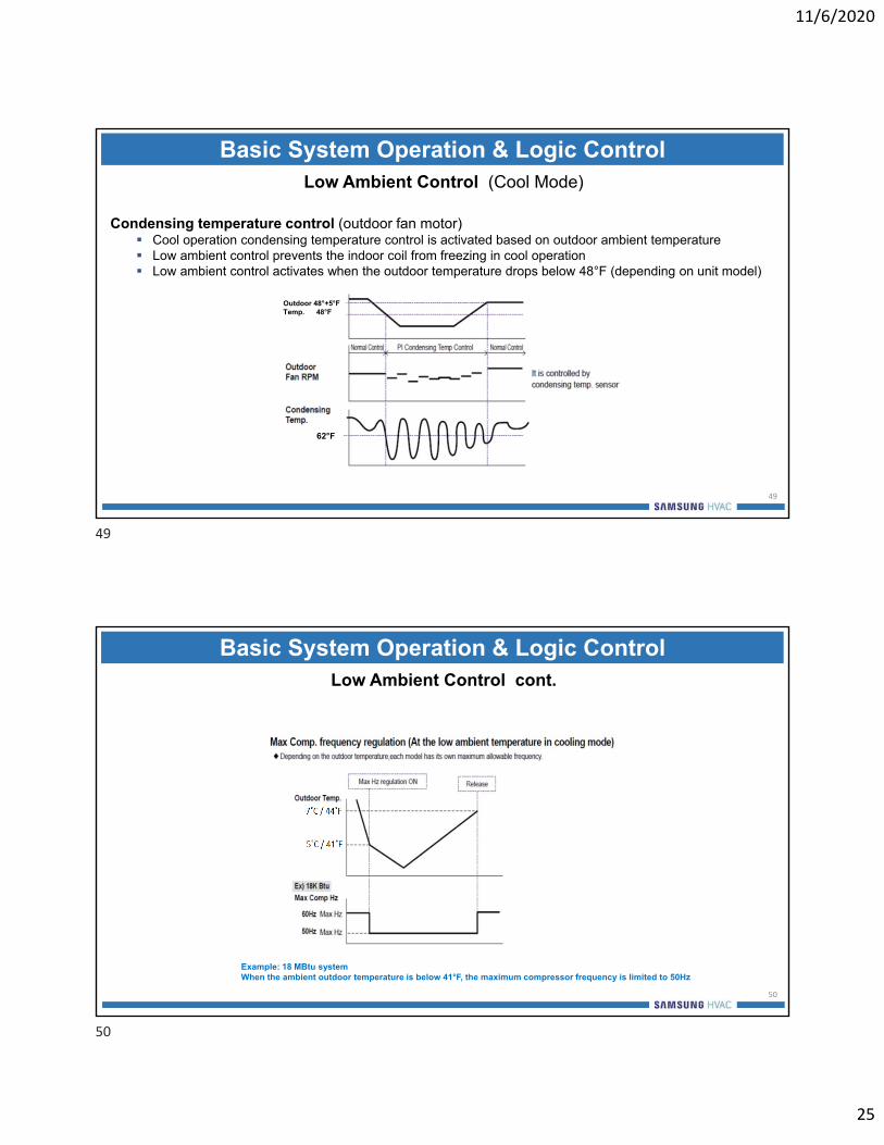
Basic System Operation & Logic ControlLow Ambient Control (Cool Mode)
Condensing temperature control (outdoor fan motor) Cool operation condensing temperature control is activated based on outdoor ambient temperature Low ambient control prevents the indoor coil from freezing in cool operation Low ambient control activates when the outdoor temperature drops below 48°F (depending on unit model)
Outdoor 48°+5°F Temp. 48°F
62°F
49
Basic System Operation & Logic ControlLow Ambient Control cont.
Example: 18 MBtu system When the ambient outdoor temperature is below 41°F, the maximum compressor frequency is limited to 50Hz
50
49
50

11/6/2020
26
Basic System Operation & Logic Control Overload Prevention Control
139°F
132°F
127°F
108°F
51
Basic System Operation & Logic ControlDefrost Control (Heat Mode)
Defrost Control – Heat operation Detects frost on the outdoor heat exchanger and removes it System changes over to the cool mode when defrost is initiated
Defrost start Compressor running and outdoor heat exchanger temperature < L2 line for continuous 120 minutes Compressor continuous running for 35 minutes and outdoor heat exchanger temperature < L1 line for continuous 3 minutes
5°F 30°F
21°F 18°F
-6°F
-6°F -4°F
52
51
52

11/6/2020
27
Basic System Operation & Logic ControlDefrost Control cont.
53
RLC Advance Service
Basic System Troubleshooting
54
53
54

11/6/2020
28
Basic System TroubleshootingSmart Install Mode
To initiate Smart Install operation press and hold: Power – Mode – SET buttons simultaneously for 4 secs.
88 Display: Progress will be indicated from 0-99
LED Display: Indicator on the indoor unit display will blink in sequence and then all indicator lights will blink.
If a malfunction is detected, the operation will end and the error code displayed on the indoor unit.
Example: Wallmount Controller
55
Basic System TroubleshootingSequence Of Items To Check
Input Voltage Rated Voltage: 208/230vac Voltage range: + 10% only System may not operate correctly if input voltage is outside of specification
Power Line & Communication Line Outdoor unit
Caution: line voltage power must not be connected to the digital communication terminals (F1 F2) AC voltage applied to terminals “F1 F2” will damage the PCB
Indoor unit line voltage Line voltage power must be connected in proper polarity from the ODU to the IDU If line voltage power is connected to the “F1 F2” terminals, an error “E101” is created
Reconnect the line voltage power to the correct terminals on the IDU Indoor unit digital communication line (AWG 16/2 with shield)
The communication wire must be connected in proper polarity from the ODU to the IDU “F1” to “F1” and “F2” to “F2”
56
55
56

11/6/2020
29
Basic System TroubleshootingTroubleshooting
□ 1st Step : Remote Controller
□ 2nd Step : Thermal Fuse of Indoor Unit
□ 3rd Step : PBA (PCB)
57
Problem: Indoor unit will not operate after the installation is completed, check the following steps:
Basic System Troubleshooting1st Step – Wireless Remote Controller
Wireless remote controller not working Check the battery voltage No display or on the controller LCD, replace batteries
LCD is displayed but IDU is not receiving any signal from the wireless remote controller Verify wireless remote controller is emitting a signal properly
Verify emitter with a digital camera or cell phone camera – NOTE: iPhone forward facing camera only Switch remote controller ON and press any button while facing the controller emitter toward the camera lens Looking at the camera LCD should see a purple or white light from the controller emitter when any controller button is pressed
– normal operation
Normal Signal
No Signal
58
57
58

11/6/2020
30
Basic System TroubleshootingWireless Remote Controller Transmit Test
Verify indoor unit operation by pressing the “Forced Operation” button If indoor unit has line voltage and it does not operate after pressing the button the indoor unit has a failure
Check the indoor unit remote controller receiver module (Vcc) Check Vcc for 5vdc measured between Vcc and GND If no 5vdc, main PCB and Panel PCB are defective
Forced operation key
V out VccGND
59
Basic System Troubleshooting2nd Step – IDU Thermal Fuse
Thermal fuse The thermal fuse is located below the terminal block of the indoor unit Thermal fuse is a protection device to eliminate the potential of overheating which could cause a fire
Loose wire connection on a terminal block can create over heating When the thermal fuse activates (open) power is terminated
Thermal fuse diagnosis Check continuity through the fuse – open/close Thermal fuse open – no 12vdc to PCB – Replace terminal block Check thermal fuse for secure connection to PCB
Check both sides of wire on the connector after disassembling
60
59
60

11/6/2020
31
Basic System Troubleshooting3rd Step – PCA (PCB)
Step Procedure The things to be checked Cause
1 -First, plug out the power plug- Pull the PBA out of control box
-Check If the both fuses on PBA are open
-Over Current-Indoor fan motor short-PBA pattern short
2 -If the operating lamp is twinkling, supply power and then check right sides
-Input voltage of BD71· Normal : 200 ∽ 240Vac
-Fuse open, Wrong power cable connection, AC part is out of order
-The voltage of between both terminal of C111(+) and (-)· Normal : 12Vdc
- Switching Trans of Power Circuitis out of order
- The voltage of between both terminal of C118(+) and (-)· Normal : 5Vdc
-Power Circuit is out of order-Load short
3 -Turn on the unit with fan RPM high & minimum setting temperature and check right sides
-The voltage between terminal #1 ∽#3 of fan motor connector(CN72)· Normal : More than DC 270V
-Fan motor is out of order
-The fan motor is not running -Fan motor connector(CN72) is out of order or
-Wire of fan motor is disconnected
-If the voltage between terminal #1 ∽#3 of fan motor connector(CN72) is zero volts
-PBA is out of order
61
RLC Advance Service
Troubleshooting Error Codes
62
61
62

11/6/2020
32
49
Basic Error Code Troubleshooting ProcessTroubleshooting Error Codes
Displayed Error Code
Determine error code description
(Service Manual)
Correct the problem
See auto backup data using SNET Pro
Error-free Operation
Reset system
Correct the problem
Operate system
Data backup with SNET Pro 2
No
Yes
No
YesAnalyze operating data
Yes
Correct the problem
Skip if no backup function
50
RLC Error Code ListTroubleshooting Error Codes
Error Description No. ofError to stop ODU Error
IDUOtherIDUs
121 Room temperature sensor is short/open 0 Normal Stop Normal122 Evaporator In temperature sensor is open/short 0 Normal Stop Normal123 Evaporator out temperature sensor is open/short 0 Normal Stop Normal128 Evaporator in temperature sensor is detached 1 Stop(R) Stop Stop129 Evaporator out temperature sensor is detached 1 Stop(R) Stop Stop153 Float switch error - second detection 1 Normal Stop Normal154 Indoor unit fan motor error 0 Normal Stop Normal161 Mixed mode operation error (simultaneous cooing & heating) 1 Normal Stop Normal162 Error in outdoor unit's EEPROM 0 Normal Stop Normal
163 Indoor unit option code is incorrect or missingOutdoor unit EEPROM data error 0 Normal Stop Normal
171 Evaporator mid sensor is detached 1 Stop(R) Stop Stop
172 Pipe in sensor is detached 1 Stop(R) Stop Stop
173 Pipe out sensor is detached 1 Stop(R) Stop Stop
186 SPI (Virus doctor) feedback error 1 Normal Normal Normal190 Pipe check failure 1 Stop Stop Stop199 Pipe check not initiated 1 Stop Stop Stop
63
64

11/6/2020
33
51
RLC Error Code ListTroubleshooting Error Codes
Error Description No. ofError to stop ODU Error
IDUOtherIDUs
201 Indoor unit quantity error - FJM 1 Stop Stop Stop
202 Communication error between outdoor unit and indoor units - FJM(while normal operating) 1 Stop Stop Stop
203 Communication error between ODU MAIN PCB and INVERTER PCB 1 Stop Stop Stop
206 Communication error between ODU MAIN PCB and HUB PCB 1 Stop Stop Stop
221 Ambient temperature sensor in the outdoor unit is open/short.ERROR LEVEL: over 4.9V (-50°C, -58°F), under 0.4V (93°C, 199.4 °F) 1 Stop Stop Stop
237 Condenser out sensor is OPEN/SHORTERROR LEVEL: over 4.9V (-50°C, -58°F), under 0.4V (93°C, 199.4°F) 1 Stop Stop Stop
246 Condenser out sensor is detached 1 Stop(R) Stop Stop
251Comp1 Discharge sensor OPEN/SHORT
ERROR LEVEL: over 4.9V (-30°C, -22°F), under 0.4V (151°C, 308°F)& ambient temperature > -10°C (14°F).
1 Stop Stop Stop
261 Compressor discharge sensor is detached 1 Stop(R) Stop Stop
52
RLC Error Code ListTroubleshooting Error Codes
Error Description No. ofError to stop ODU Error
IDUOtherIDUs
320 OLP sensor is open/shortERROR LEVEL: over 4.95V (-30°C), under 0.5V (151°C) 1 Stop Stop Stop
330 Hub in 1 sensor is open/short 1 Stop Stop Stop331 Hub in 2 sensor is open/short 1 Stop Stop Stop332 Hub in 3 sensor is open/short 1 Stop Stop Stop333 Hub in 4 sensor is open/short 1 Stop Stop Stop334 Hub in 5 sensor is open/short 1 Stop Stop Stop335 Hub out 1 sensor is open/short 1 Stop Stop Stop336 Hub out 2 sensor is open/short 1 Stop Stop Stop337 Hub out 3 sensor is open/short 1 Stop Stop Stop338 Hub out 4 sensor is open/short 1 Stop Stop Stop339 Hub out 5 sensor is open/short 1 Stop Stop Stop401 Compressor trip by freezing protection 0 Stop Normal Normal404 Compressor trip by overload protection 3 Stop Normal Normal416 Compressor trip by discharge temperature protection 3 Stop Normal Normal419 Outdoor unit’s EEV opening failure error (EEV is blocked) 1 Stop(R) Stop Stop
422 Outdoor unit’s EEV closing failure error (EEV is leaking) 1 Stop(R) Stop Stop440 Heating start restriction due to high ambient temperature over 86°F 0 Stop Normal Normal441 Cooling start restriction due to low ambient temperature under 14°F 0 Stop Normal Normal458 Outdoor fan motor error 1 Stop Stop Stop
65
66

11/6/2020
34
53
RLC Error Code ListTroubleshooting Error Codes
Error Description No. ofError to stop ODU Error
IDUOtherIDUs
461 Compressor starting failure (5 times) 5 Stop Normal Normal462 Compressor trip by current protection control 3 Stop Normal Normal463 Compressor trip by OLP temperature protection 3 Stop Normal Normal464 IPM over-current 9 Stop Normal Normal465 Over current error in Inverter compressor(Over 30A) 9 Stop Normal Normal466 Voltage in DC Link is below 150V or over 410V in inverter PBA 0 Stop Normal Normal467 Abnormal RPM or wire is disconnected in inverter compressor 3 Stop Normal Normal468 Current sensor error (Open / Short) 1 Stop Stop Stop 469 DC voltage sensor error (Open / Short) 1 Stop Stop Stop 470 Outdoor unit EEPROM Error 1 Stop(R) Stop Stop472 Inverter micom zero-crossing error 1 Stop Stop Stop 473 Inverter compressor lock error 3 Stop Normal Normal474 Inverter IPM heat sink sensor error (Open / Short) 1 Stop Stop Stop 475 Inverter fan 2 error 1 Stop Stop Stop 483 Error due to over current 1 Stop Stop Stop 484 PFC overload(over current) error 0 Stop Normal Normal485 Inverter 1 input current sensor error (Open / Short) 1 Stop Stop Stop 486 Error due to over voltage/low voltage of fan motor 3 Stop Normal Normal500 Inverter 1 IPM overheat error 9 Stop Normal Normal554 Refrigerant leak error 1 Stop(R) Stop Stop 660 Inverter boot code error 1 Stop Stop Stop
54
RLC Error Code Display - Whisper/Pearl/Wind Free/QuantumTroubleshooting Error Codes
IDU error code status is displayed at the LED display in the lower right hand corner behind the powered louver (Quantum LED display on lower right hand unit cover)
ODU errors displayed with the Red, Green & Yellow LEDs on the main PCB
LED’s
Example list
Example list
67
68

11/6/2020
35
55
RLC Error Code Display – MAX AQ*036Troubleshooting Error Codes
IDU error code status is displayed with LEDs located on the lower right hand unit cover
ODU error code status displayed on the 7-segment display on the main PCBAll error codes begin with “E” followed by 3 numbers
Example list
Troubleshooting Error CodesCommon Error Codes
E101 – Indoor unit communication error. Indoor unit cannot receive any data from outdoor unit.E121 – Room TH sensor errorE153 – Indoor float switch error.E154 – Indoor unit fan motor error.E190 – Pipe check failureE199 – Pipe check not initiated. (usually happens on new installs when unit is first powered on.)E201 – Indoor unit quantity error. Settings on outdoor PCB wrong or duplicate address.E203 – Communication error of ODU main & inverter PCB’sE320 – OLP (Over Load Protector) open or shortE416 – Compressor stop due to high discharge pressureE458 – Outdoor fan ErrorE461 – Compressor failure to startE464 – IPM over currentE467 – Compressor rotation error – Abnormal compressor operationE470 – ODU PCB EEPROM error
70
69
70

11/6/2020
36
Troubleshooting Error CodesE101 – IDU Communication Error
Check the incoming ac voltage : 208/230vac Step down transformer is recommended If supply voltage is above 245vac
Make sure communication control wire is 16/2 AWG stranded with shield Verify the control wire shield is grounded at the outdoor unit only Make sure the unit is wired in proper polarity (F1 to F1, F2 to F2, etc.) The control wire must not be run in the same conduit as ac voltage wiring.
Control wire must be run with at least a 2” air gap from conduit with ac voltage wiring Control wire must be run with no splices or junction boxes
Must be a continuous run from indoor to outdoor unit Are there any condensate pumps on system that are tied into F1 and F2?
The F1 F2 communication circuit cannot be broken (switched) or spliced Are there any breaks in the control wires? (Connect ends and Ohm out) Try option coding the indoor unit.
71
Troubleshooting Error CodesE121 – Room TH Sensor ErrorCheck:
Is the indoor unit room temperature sensor wire harness properly connected to the PCB Is the sensor placed correctly on the return air side of the coil Check the resistance value in relation to the ambient temperature Is there a separate field installed condensate pump in this unit with the float switch wired into the unit room
sensor leads: Check the condensate water level and the pump float switch status (open/close) If open, is there a blockage in the condensate removal circuit or pump failure
72
71
72

11/6/2020
37
Troubleshooting Error CodesE153 – IDU Float Switch Error (cassette & ducted units)
This error code will only show up on ducted or cassette units that are equipped with a condensate lift pump If a factory condensate lift pump is installed in a unit that doesn’t normally have one, and they initialize the pump in
the install option codes, this error can occur as well.
Test the float switch plug on PCB to make sure it is closed. This is a normally closed switch. If it is opened, check to see if drain pan is full of water. If drain pan has no water, the float switch could be stuck or defective. If full of water check to make sure there is voltage to the drain pump. Make sure the drain hose is not clogged or pinched shut. If voltage is present replace pump. No voltage replace indoor PCB
Float SwitchPlug
Drain pump powerPlug
73
Troubleshooting Error CodesE154 – IDU Fan Motor Error
Is your incoming voltage correct? What mode are you in? In heating mode fan will not run till indoor coil reaches 93°F Does the fan spin freely? Are the filters and evaporator coil clean? Is the fan plugged into PCB properly? Cycle power does the fan run at all? Try option coding the indoor unit. Check the voltage of DC Link between #1 & #3 in cooling mode
Normal range: 270V – 320 V Check the DC voltage between #3 & #5 or #3 & #6 in cooling mode
Normal range: 5vdc – 10vdc If voltage is ok, replace the indoor fan motor. If voltage is not correct replace indoor PCB
74
73
74

11/6/2020
38
Troubleshooting Error CodesE154 – IDU Fan Motor Error cont.
CN 72 Check AC Voltage
75
62
E154 – Indoor fan motor error cont.
Determine which components have malfunctioned:Motor, Wire harness connection or PCB
Verify the fan motor wire harness connector is securely connected to the PCB
Switch power off to the outdoor unit and after 15 minutes disconnect the fan motor harness from CN72 on the PCB
Check continuity between each pin: #1~#6 Replace fan motor if short is detected If no shorts – reconnect fan motor harness to PCB (CN72)
Restore power to the outdoor unit Check the voltage of DC Link CN72 (between #1& #3) in cooling mode
Normal range : 270V~340V (≈1.41 X AC Voltage Input) Check the DC voltage between #3 & #5 or between #3 and #6 in cooling
mode Normal range: 5vdc~10vdc (when fan is running)
With fan motor off, verify voltage fluctuation of 0vdc to 15vdc when fan is manually turned
If the voltage value is within the normal range: replace the fan motor
Troubleshooting Error Codes
CN72
Example Indoor Unit Main PCB
75
76

11/6/2020
39
63
Troubleshooting Error CodesE190 – Pipe check failure FJM series
There are only a few causes of this problem
Refrigerant piping crossed. Small or large line from one unit swapped on the ports of another unit.
Verify all refrigerant piping connections to the outdoor unit. Indoor coil thermistor sensor reading out of range or separated from indoor coil.
Test the indoor coil sensor (refer to10KΩ sensor chart) Verify thermistor sensor is attached properly to the coil.
Troubleshooting Error CodesE199 – Pipe Check Not Initiated - FJM
This error code is most typical on initial power up. You should only see this code on the FJM series. If none of the dip switches on the outdoor unit are changed from factory. You should see this code on the outdoor unit once power is applied. Set the rotary dial to the number of indoor units you have and then press the K1 button one time to initiate the pipe check operation on the system. You will see what looks like a sideways “T” and a five on the left hand screen. This is showing you the system is going through its pipe check. If it fails you will get an error code. This process can last up to an hour depending on the amount of units connected to the system. Once tracking is complete it will flash through the addresses on the left hand screen.
78
77
78

11/6/2020
40
Troubleshooting Error CodesE201 – IDU Quantity Error - FJM
This is a communication error. This error will be displayed when the outdoor unit cannot communicate with the number of indoor units you have set on the outdoor unit PCB rotary dial. For example, you have it set for 4 but the unit can only find 3.You will also get this error if you have duplicate indoor addresses, 2 indoor units with the same address.
Check the following on all the indoor units:
If all this checks out. Try to narrow it down to which unit it cannot find. Power system off and remove all but one set of F1 and F2 wires. Set rotary dial to one and
power system back on. See if it finds that one unit. If so continue on until you locate the unit it wont find. Problem is usually in the wire. If not replace indoor PCB.
Check the incoming ac voltage: 208/230vac If above 245V use step-down transformer.
Make sure communication control wire is 16/2 AWG with shield Verify the control wire shield is grounded at the outdoor unit only Make sure the unit is wired in proper polarity (F1 to F1, F2 to F2, etc.) The control wire must not be run in the same conduit as ac voltage wiring.
Control wire must be run with at least a 2” air gap from conduit with ac voltage wiring Control wire must be run with no splices or junction boxes
Must be a continuous run from indoor to outdoor unit Are there any condensate pumps on system that are tied into F1 and F2?
Cannot break communication circuit Are there any breaks in the control wires? (Connect ends and Ohm out) Verify addresses are correct per Installation Manual (manual addressing only)
79
Troubleshooting Error CodesE203 – Communication Error ODU Main & Inverter PCB’s
This is strictly an outdoor PCB communication error. This happens when the main and inverter PCB’scannot communicate.** Sometimes these error codes can be caused by a spike in voltage and just cycling power to the system will correct the issue
Check supply voltage: 185vac – 245vac – If above 245vac install step-down transformer Inspect reactor wire – burned or melted Unplug outdoor fan motor(s). Motors are dc powered and if there is an internal short in the
motor, it can cause a problem with the dc communications If the error code goes away after the motor is unplugged, replace the fan motor If the unit has 2 fan motors (MAX - AQX36), pinpoint which motor is causing the
issue and replace If the error still does not go away, replace the outdoor control assembly
80
79
80

11/6/2020
41
Troubleshooting Error CodesE320 – Overload Protector Open/Short (OLP)
This error pertains to the outdoor unit OLP (Over Load Protector) sensor.
Does the system run or does the error code appear right away? If it appears right away, locate the sensor plug designation and ohm the sensor at 77°F
This is a 200KΩ sensor – refer to chart If sensor is out of range replace. If sensor is within range reseat connection and test. If error occurs again replace outdoor
PCB If system runs before error, check running pressure.
Over or under charge could cause this error. Make sure outdoor fan motor is running. Make sure coil is clean. If in heat mode make sure indoor fan is coming on and filter is clean.
If not refer to E154 troubleshooting Make sure there is no obstructions in front of indoor or outdoor units. Check the discharge sensor
81
Troubleshooting Error CodesE416 – Compressor Stop – High Discharge Temperature
If error appears right away Locate the sensor plug designation and ohm sensor. This is a
200KΩ sensor at 77°F. ( Use chart ) If sensor is out of range replace. If sensor is within range reseat connection and test. If error
occurs again replace outdoor PCB
This error is protection for the compressor when discharge temperature is too high. Does the system run before getting this error?
If system runs before error Check running pressure. Over or under charge could cause this. Verify outdoor fan motor is running. Make sure coil is clean.
If in heat mode make sure indoor fan is coming on and filter is clean.(If not refer to E154 troubleshooting)
Make sure there is no obstructions in front of indoor or outdoor units.
82
81
82

11/6/2020
42
Troubleshooting Error CodesE458 – ODU BLDC Fan Error
PF2(Platform2)Model: 9k,12k,18k Btu/h PF3(Platform3)
Model : 24k Btu/h
Check Connector
Check Connector
Check for obstacles or locked fan
83
Troubleshooting Error CodesE458 – ODU BLDC Fan Error cont.
To determine which parts are out or order, follow the procedure belowCAUTION: Never unplug a BLDC motor while the unit is powered up. Power must be switched off for at least 15 minutes before removing the plug from the PCB. Check the FAN connector is tightly connected to PBA
If fan connector is tightly connected Check if DC_ link voltage in DC Capacitor (PF2:CE101, PF3:CE054) in cooling
mode Normal range : 279V ~ 342V (at AC 220 V input)
Check if DC voltage between #3 and #5 or between #3 and #6 is changing(up and down)
If so, it is normal
If checked value is within normal range, Fan motor is defective
84
83
84

11/6/2020
43
Troubleshooting Error CodesBLDC Fan Motor
BLUE - Fan Feedback Pulse _
YELLOW - Fan RPM Command _
WHITE – 15vdc_
BLACK - Ground_
RED – 340vdc_
Blank
6
5
4
3
2
1
6-pin/5-wire connector
85
Reminder: Never unplug a BLDC motor while the PCB is still powered up; wait 15 minutes after power is switched off
Troubleshooting Error CodesE461 – Compressor Failure To Start
86
85
86

11/6/2020
44
73
E461 – Compressor failure to startCheck compressor malfunction with VOM tester or a Megohmmeter
Switch the power off to the ODU and wait at least 15 minutes Remove compressor wires from terminal block
Use the VOM to check compressor winding resistance on all three phases Fail: 0Ω or over 2Ω
Use a Megohmmeter to measure the winding insulation resistance Fail: Less than 1MΩ from wire terminal U – V – W to chassis
Resistance test Normal range
Resistance value of (U↔V,V↔W,W↔U)on compressor less than 2Ω
Compressor winding insulation test >1MΩ
U V
W
Troubleshooting Error Codes
74
E461 – Compressor failure to start
ActionMeasuring point Normal
range Remark+ -
Measure the diode voltage
values
U P
0.3~0.7V
V P
W P
N U
N V
N W
Measure the resistance
values
U P
More than 500kΩ
V P
W P
N U
N V
N W
+
-
Check the Inverter using the VOM
Measure the diode voltage values (preferred) or the diode resistance values
NOTE: When performing the diode resistance test on the inverter, power to the ODU must be switched off for at least 15 minutes.
Troubleshooting Error Codes
87
88

11/6/2020
45
Troubleshooting Error CodesE464 – IPM Overcurrent
IPM Overcurrent protection/OC error/DC peak error
Control: When peak current of the compressor exceeds the designed current, compressor stops operation immediately
Protection purpose: Compressor rotor magnets demagnetizing IPM breakdown
Cause: Indoor airflow blocked in heating mode – discharge louver closed or blockage of air inlet Compressor winding short Disconnected wiring to compressor while in operation Compressor lock or rotor rotation error Excessive compressor load during low speed operation PCB short circuit
89
Troubleshooting Error CodesE464 – IPM Overcurrent cont.
Verify that the service valves are open !!!! Verify supply voltage 208/230vac Check outdoor display lights are matching the main PCB Inspect the main PCB for burn marks or melted components Check connector between PCB and compressor
Corrosion – loose connections – wire polarity Check compressor terminal connections
Tight connections – corrosion – burnt wires or terminals With compressor unplugged power system back up. Do you get the E464 error immediately?
If so replace outdoor control assembly. If you get compressor start error(E461 or E467) the problem is in the compressor, replace compressor. Ohm compressor windings. This is a 3 phase DC compressor so all windings should be equal and a fairly low
ohm value. Usually below 2Ω’s Check with multi meter to bare shell of compressor. Should have nothing to ground on any leg. If compressor insulation test fails, replace compressor
90
89
90

11/6/2020
46
Troubleshooting Error CodesE461 – E467 Troubleshooting Procedures
Check your incoming voltage. Make sure it is within range 185V-253V Pull disconnect and locate the compressor plug. Ohm compressor windings.
This is a 3 phase compressor so all windings should be equal and a fairly low ohm value. Usually below 2Ω’s Check with multi meter to bare shell of compressor. Should have nothing to ground on any leg. If compressor tests ok, use inverter checker to test inverter board. Use plug going down to the compressor.
If bad replace outdoor control assembly. IF ALL TESTS ON COMPRESSOR AND BOARDS TEST OK SAMSUNG RECOMMENDS STARTING WITH CONTROL
ASSEMBLY. THIS DOES NOT MEAN COMPRESSOR CAN NOT BE MECHANICALLY LOCKED. IF CONTROL BOARDS FAIL TO FIX. REPLACE COMPRESSOR.
91
Troubleshooting Error CodesE467 – Compressor Rotation Error
92
91
92
11/6/2020
47
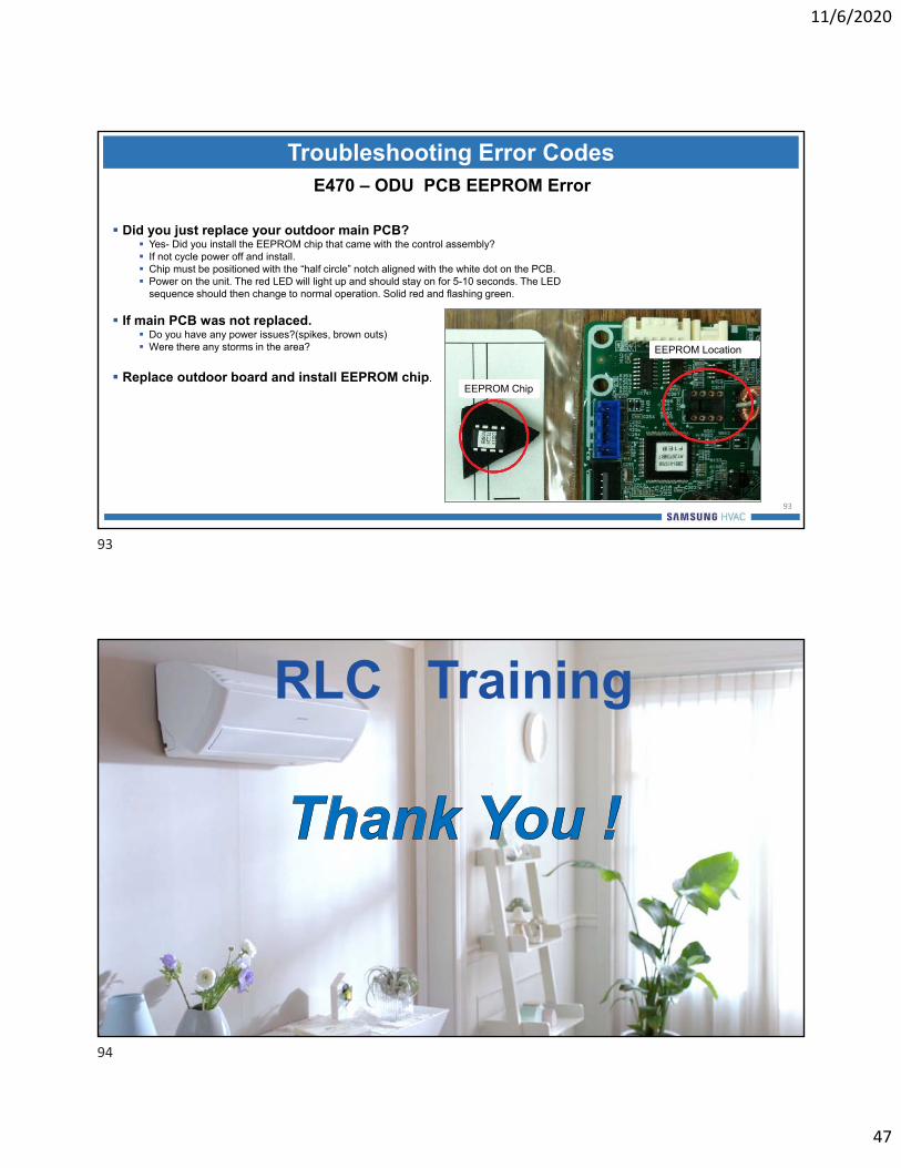
Troubleshooting Error CodesE470 – ODU PCB EEPROM Error
Did you just replace your outdoor main PCB? Yes- Did you install the EEPROM chip that came with the control assembly? If not cycle power off and install. Chip must be positioned with the “half circle” notch aligned with the white dot on the PCB. Power on the unit. The red LED will light up and should stay on for 5-10 seconds. The LED
sequence should then change to normal operation. Solid red and flashing green.
If main PCB was not replaced. Do you have any power issues?(spikes, brown outs) Were there any storms in the area?
Replace outdoor board and install EEPROM chip.
93
EEPROM Chip
EEPROM Location
RLC Training
93
94

11/6/2020
48
Exclusive Dealer FeaturesEasy System Error Code Diagnostics & New System Registration
Dealer Mobile App
Dealer support at your fingertips Android or IOS devices
There is an easy way to access the error code lists with descriptions by simply using the
Dealer Mobile app on your Android or IOS devices
Error Code Diagnostics
96
All Samsung Residential/Light Commercial and Commercial systems implement processor based self-diagnostics which generate error codes to identify specific operational and component issues
System error code lists are included in the Installation and Service Manuals & DVMS Error Code Booklet
95
96

11/6/2020
49
Error Code Diagnostics
97
The error code listing with descriptions for the complete Samsung product line is easily accessed through the Dealer Mobile App.
Select “Error” tab from Menu
You can select the video description of the error code
Enter the error code or enter the type of error i.e. “Communication”
Error codes greatly enhance the diagnostic procedures required to quickly and accurately analyze and resolve system component and operation issues
Launch the app and sign in
Samsung System Registration
98
New Samsung systems can be conveniently registered through the Dealer Mobile App
Launch the app and sign in
Select the “Registration” tab
from Menu
Enter the installation information including the end-user email address
Select the installation type: ResidentialCommercial (comfort cooling) Commercial (non-comfort cooling)Select installation date
97
98
11/6/2020
50
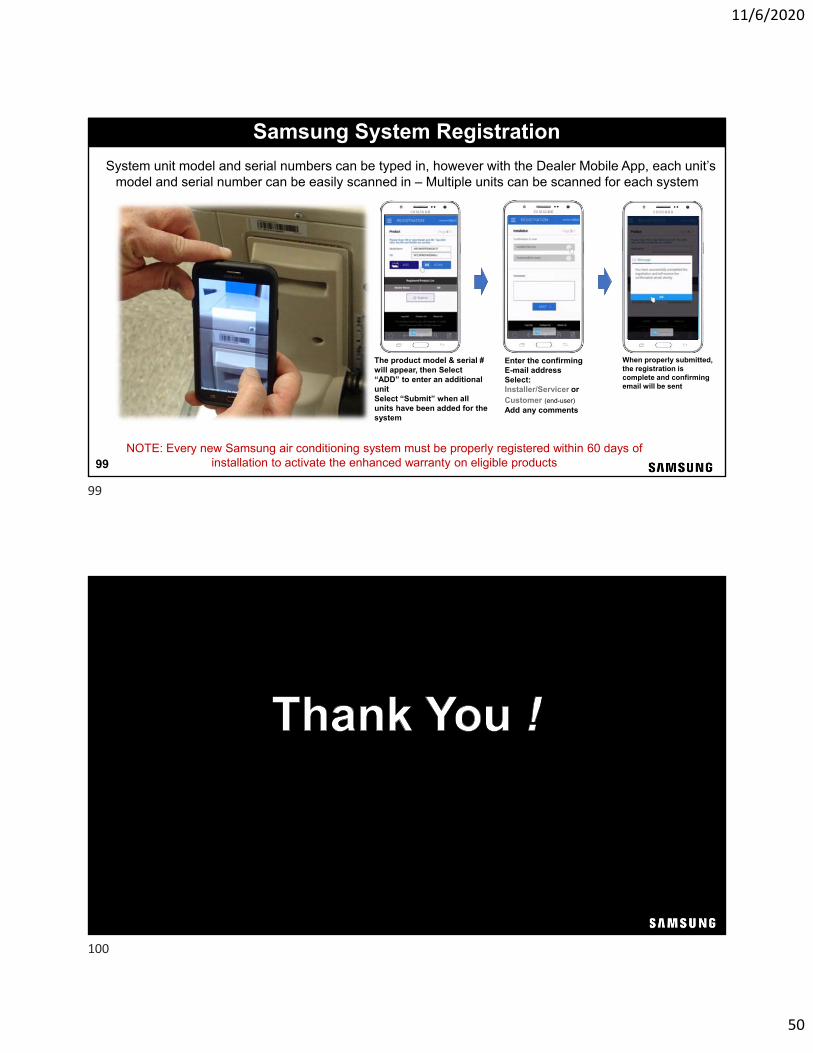
Samsung System Registration
99
System unit model and serial numbers can be typed in, however with the Dealer Mobile App, each unit’s model and serial number can be easily scanned in – Multiple units can be scanned for each system
NOTE: Every new Samsung air conditioning system must be properly registered within 60 days of installation to activate the enhanced warranty on eligible products
The product model & serial # will appear, then Select “ADD” to enter an additional unitSelect “Submit” when all units have been added for the system
When properly submitted, the registration is complete and confirming email will be sent
Enter the confirming E-mail address Select: Installer/Servicer orCustomer (end-user)Add any comments
99
100

11/6/2020
51
Additional Samsung Training
DVM S ECO Training 2-day & 1-dayIntroduction & Basic InstallationRefrigerant Piping InstallationCommissioning & Configuration
DVM S Water Training 1-dayIntroduction & Basic InstallationCommissioningPrerequisite training required: DVM S Introduction and Basic Installation Training 2-day
DVM Chiller Training 1-dayIntroduction & Basic InstallationCommissioning
Register for all DVM S and other Samsung HVAC product training at: www.schoox.com/login.php
DVM S Training 2-dayAdvance Service & Troubleshooting
DVM S Training 2-dayIntroduction & Basic InstallationRefrigerant Piping InstallationCommissioning & Configuration
101