robotics applicationmanual ethernet/ipanybusadapter
TRANSCRIPT

ROBOTICS
Application manualEtherNet/IP Anybus Adapter

Trace back information:Workspace 19D version a3Checked in 2019-12-04Skribenta version 5.3.033

Application manualEtherNet/IP Anybus Adapter
RobotWare 6.10.01
Document ID: 3HAC050997-001Revision: D
© Copyright 2007-2019 ABB. All rights reserved.Specifications subject to change without notice.

The information in this manual is subject to change without notice and should notbe construed as a commitment by ABB. ABB assumes no responsibility for any errorsthat may appear in this manual.Except as may be expressly stated anywhere in this manual, nothing herein shall beconstrued as any kind of guarantee or warranty by ABB for losses, damages topersons or property, fitness for a specific purpose or the like.In no event shall ABB be liable for incidental or consequential damages arising fromuse of this manual and products described herein.This manual and parts thereof must not be reproduced or copied without ABB'swritten permission.Keep for future reference.Additional copies of this manual may be obtained from ABB.
Original instructions.
© Copyright 2007-2019 ABB. All rights reserved.Specifications subject to change without notice.

Table of contents7Overview of this manual ...................................................................................................................9Product documentation ....................................................................................................................
11Safety ................................................................................................................................................12Network security ...............................................................................................................................13Terminology ......................................................................................................................................
151 Introduction151.1 What is EtherNet/IP? ..........................................................................................161.2 The EtherNet/IP anybus adapter for IRC5 ..............................................................
192 Hardware overview192.1 Main computer DSQC1000 ..................................................................................
233 Software overview233.1 Information about the anybus adapter ...................................................................253.2 CIP routing .......................................................................................................253.2.1 What is CIP routing? ................................................................................263.2.2 CIP routing for IRC5 .................................................................................283.2.3 Information about CIP routing ....................................................................
314 Configuring the anybus adapter314.1 Recommended working procedure .......................................................................324.2 Configuring the anybus adapter ...........................................................................344.3 Configuring the external scanner ..........................................................................354.4 Configuring CIP routing ......................................................................................
375 System parameters375.1 Introduction ......................................................................................................385.2 Type Industrial Network ......................................................................................385.2.1 Address .................................................................................................395.2.2 Subnet Mask ..........................................................................................405.2.3 Gateway ................................................................................................415.3 Type EtherNet/IP Internal Anybus Device ..............................................................415.3.1 Connection Input Size ..............................................................................425.3.2 Connection Output Size ............................................................................435.3.3 Connection Timeout Multiplier ...................................................................445.4 Type Route ......................................................................................................445.4.1 Name ....................................................................................................455.4.2 Industrial Network ...................................................................................465.4.3 Port ID ..................................................................................................
47Index
Application manual - EtherNet/IP Anybus Adapter 53HAC050997-001 Revision: D
© Copyright 2007-2019 ABB. All rights reserved.
Table of contents

This page is intentionally left blank
Overview of this manualAbout this manual
This manual describes the option EtherNet/IP Anybus Adapter and containsinstructions for the configuration.
UsageThis manual should be used during installation and configuration of the EtherNet/IPanybus adapter and upgrading of the option EtherNet/IP Anybus Adapter.
Who should read this manual?This manual is intended for
• Personnel that are responsible for installations and configurations of industrialnetwork hardware/software
• Personnel that make the configurations of the I/O system• System integrators
PrerequisitesThe reader should have the required knowledge of
• Mechanical installation work• Electrical installation work
References
Document references
Document IDReference
3HAC050992-001Applicationmanual - DeviceNetMaster/Slave
3HAC032104-001Operating manual - RobotStudio
3HAC050941-001Operating manual - IRC5 with FlexPendant
3HAC047136-001Product manual - IRC5
3HAC050948-001Technical reference manual - System para-meters
3HAC050998-001Applicationmanual - EtherNet/IP Scanner/Ad-apter
3HAC047400-001Product specification - Controller IRC5
Other references
DescriptionReference
The web site of ODVA (Open DeviceNetVendor Association).
www.odva.org
ODVA SpecificationCommon Industrial Protocol (CIP) Edition 3.0
ODVA SpecificationEtherNet/IP Specification Edition 1.2
Continues on next pageApplication manual - EtherNet/IP Anybus Adapter 73HAC050997-001 Revision: D
© Copyright 2007-2019 ABB. All rights reserved.
Overview of this manual
Revisions
DescriptionRevision
First edition.-Released with RobotWare 6.0.
Released with RobotWare 6.01.• Minor corrections.• System parameter Connection removed from Industrial Network.
A
Released with RobotWare 6.02.• Updated the path to the template files, see Template I/O configuration
file on page 23.
B
Released with RobotWare 6.05.CAdded new parameter Connection Timeout Multiplier on page 43 in sectionSystem Parameters.
Released with RobotWare 6.10.01.• Cfg name removed from entire manual.
D
8 Application manual - EtherNet/IP Anybus Adapter3HAC050997-001 Revision: D
© Copyright 2007-2019 ABB. All rights reserved.
Overview of this manualContinued

Product documentationCategories for user documentation from ABB Robotics
The user documentation from ABB Robotics is divided into a number of categories.This listing is based on the type of information in the documents, regardless ofwhether the products are standard or optional.All documents can be found via myABB Business Portal, www.myportal.abb.com.
Product manualsManipulators, controllers, DressPack/SpotPack, and most other hardware isdelivered with a Product manual that generally contains:
• Safety information.• Installation and commissioning (descriptions of mechanical installation or
electrical connections).• Maintenance (descriptions of all required preventive maintenance procedures
including intervals and expected life time of parts).• Repair (descriptions of all recommended repair procedures including spare
parts).• Calibration.• Decommissioning.• Reference information (safety standards, unit conversions, screw joints, lists
of tools).• Spare parts list with corresponding figures (or references to separate spare
parts lists).• References to circuit diagrams.
Technical reference manualsThe technical reference manuals describe reference information for roboticsproducts, for example lubrication, the RAPID language, and system parameters.
Application manualsSpecific applications (for example software or hardware options) are described inApplication manuals. An application manual can describe one or severalapplications.An application manual generally contains information about:
• The purpose of the application (what it does and when it is useful).• What is included (for example cables, I/O boards, RAPID instructions, system
parameters, software).• How to install included or required hardware.• How to use the application.• Examples of how to use the application.
Continues on next pageApplication manual - EtherNet/IP Anybus Adapter 93HAC050997-001 Revision: D
© Copyright 2007-2019 ABB. All rights reserved.
Product documentation

Operating manualsThe operating manuals describe hands-on handling of the products. The manualsare aimed at those having first-hand operational contact with the product, that isproduction cell operators, programmers, and troubleshooters.
10 Application manual - EtherNet/IP Anybus Adapter3HAC050997-001 Revision: D
© Copyright 2007-2019 ABB. All rights reserved.
Product documentationContinued

SafetySafety of personnel
When working inside the robot controller it is necessary to be aware ofvoltage-related risks.A danger of high voltage is associated with the following parts:
• Devices inside the controller, for example I/O devices, can be supplied withpower from an external source.
• The mains supply/mains switch.• The power unit.• The power supply unit for the computer system (230 VAC).• The rectifier unit (400-480 VAC and 700 VDC). Capacitors!• The drive unit (700 VDC).• The service outlets (115/230 VAC).• The power supply unit for tools, or special power supply units for the
machining process.• The external voltage connected to the controller remains live even when the
robot is disconnected from the mains.• Additional connections.
Therefore, it is important that all safety regulations are followed when doingmechanical and electrical installation work.
Safety regulationsBefore beginning mechanical and/or electrical installations, ensure you are familiarwith the safety regulations described in Operating manual - General safetyinformation1 .
1 This manual contains all safety instructions from the product manuals for the manipulators and the controllers.
Application manual - EtherNet/IP Anybus Adapter 113HAC050997-001 Revision: D
© Copyright 2007-2019 ABB. All rights reserved.
Safety
Network securityNetwork security
This product is designed to be connected to and to communicate information anddata via a network interface. It is your sole responsibility to provide, andcontinuously ensure, a secure connection between the product and to your networkor any other network (as the case may be).You shall establish and maintain any appropriate measures (such as, but not limitedto, the installation of firewalls, application of authentication measures, encryptionof data, installation of anti-virus programs, etc) to protect the product, the network,its system and the interface against any kind of security breaches, unauthorizedaccess, interference, intrusion, leakage and/or theft of data or information. ABBLtd and its entities are not liable for damages and/or losses related to such securitybreaches, any unauthorized access, interference, intrusion, leakage and/or theftof data or information.
12 Application manual - EtherNet/IP Anybus Adapter3HAC050997-001 Revision: D
© Copyright 2007-2019 ABB. All rights reserved.
Network security
TerminologyTerms
ExplanationTerm
I/O device that is controlled by a scanner in an Ether-net network. Previously, ABB documentation used theterm slave.
Adapter
Common Industrial Protocol.CIPProtocol that DeviceNet and EtherNet/IP are basedon.
See Scanner.ClientSome documents use the term client, whereas theABB documentation use the term Scanner for Ether-Net/IP industrial network.
Electronic Data Sheet.EDSEDS files contain the configuration details relevant toCIP devices.
An explicit message is a request or response orientedcommunication with other devices. These messagesare mostly configuration data.
Explicit Messages
Implicit messages are exchanged between I/O connec-tions. No messaging protocol is contained within themessage data as with Explicit messaging. Implicitmessages can be point to point (unicast) or multicastand are used to transmit application specific I/O data.
Implicit Messages
Describes when the robot controller acts as an Ether-Net/IP adapter on the EtherNet/IP network.
Internal adapter
Describes when the robot controller acts as an Ether-Net/IP scanner on the EtherNet/IP network.
Internal scanner
Connector for Local Area Network.LAN
Ethernet contact with IP67 classification.M12
See term Scanner.Master
Open DeviceNet Vendor Association.ODVAOrganization for networks built on CIP, for exampleDeviceNet and EtherNet/IP.
Standard Ethernet contact.RJ45
Controls other I/O devices (adapters) in an Ethernetnetwork. Previously, ABB documentation used theterm Master.
Scanner
See term Adapter.ServerSome documents use the term server, whereas theABB documentation use the term adapter for Ether-Net/IP industrial network.
See term Adapter.Slave
Port for Wide Area Network.WAN
Application manual - EtherNet/IP Anybus Adapter 133HAC050997-001 Revision: D
© Copyright 2007-2019 ABB. All rights reserved.
Terminology

This page is intentionally left blank

1 Introduction1.1 What is EtherNet/IP?
GeneralEtherNet/IP is a communications link to connect industrial devices.The EtherNet/IP (EtherNet Industrial Protocol) is managed by ODVA (OpenDeviceNet Vendors Association). It is a well established industrial Ethernetcommunication system with good real-time capabilities. EtherNet/IP extendscommercial off-the-shelf Ethernet to the CIP (Common Industrial Protocol)— thesame upper-layer protocol and object model found in DeviceNet and ControlNet.CIP allows EtherNet/IP and DeviceNet system integrators and users to apply thesame objects and profiles for plug-and-play interoperability among devices frommultiple vendors and in multiple sub-nets. Combined, DeviceNet, ControlNet andEtherNet/IP promote transparency from sensors to the enterprise software.
Examples of applicationsHere are some examples of EtherNet/IP applications:
• Peer-to-peer data exchange where an EtherNet/IP product can produce andconsume messages
• Scanner/adapter operation defined as a proper subset of peer-to-peer• An EtherNet/IP product can function as a client or server, or both
StandardizationEtherNet/IP is standardized according to the International standard IEC 61158 andEtherNet/IP devices are certified by ODVA for interoperability and conformance.
DataThe following table specifies a number of EtherNet/IP data.
Ethernet based Control Level network with CIP application protocolNetwork type
Standard Off the Shelf (COTS) Ethernet cables and connectors.Installation10/100/1000 Mbit/s TX Ethernet cable or fibre optics.RJ45, M12 or fibre optic connectors.
10, 100, 1000 Mbit/sSpeed
EDS fileThe configuration process is based on EDS files (Electronic Data Sheet) which arerequired for each EtherNet/IP device. EDS files are provided by the devicemanufacturers. It contains electronic descriptions of all relevant communicationparameters and objects of the EtherNet/IP device.
Application manual - EtherNet/IP Anybus Adapter 153HAC050997-001 Revision: D
© Copyright 2007-2019 ABB. All rights reserved.
1 Introduction1.1 What is EtherNet/IP?

1.2 The EtherNet/IP anybus adapter for IRC5
GeneralThe EtherNet/IP anybus adapter for IRC5 is inserted into an expansion board ontop of the main computer unit in the robot controller.The EtherNet/IP anybus adapter, DSQC 669, requires the main computerDSQC1000.
OptionsWith option EtherNet/IP Anybus Adapter, the IRC5 controller can act as an adapteron the EtherNet/IP network.
Note
If EtherNet/IP scanner functionality is required, then the option EtherNet/IPScanner/Adapter must be used.For more information see, Application manual - EtherNet/IP Scanner/Adapter.
Continues on next page16 Application manual - EtherNet/IP Anybus Adapter
3HAC050997-001 Revision: D© Copyright 2007-2019 ABB. All rights reserved.
1 Introduction1.2 The EtherNet/IP anybus adapter for IRC5
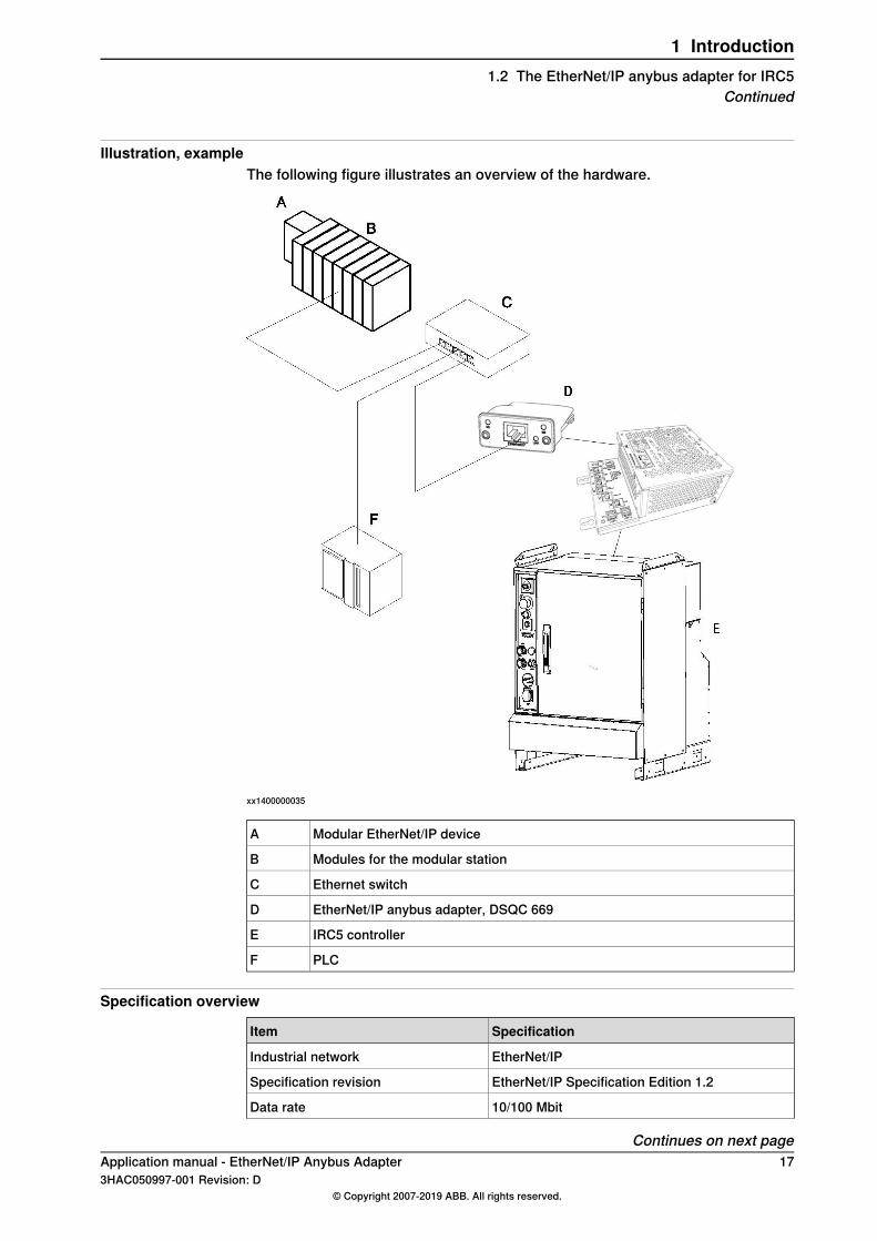
Illustration, exampleThe following figure illustrates an overview of the hardware.
xx1400000035
Modular EtherNet/IP deviceA
Modules for the modular stationB
Ethernet switchC
EtherNet/IP anybus adapter, DSQC 669D
IRC5 controllerE
PLCF
Specification overview
SpecificationItem
EtherNet/IPIndustrial network
EtherNet/IP Specification Edition 1.2Specification revision
10/100 MbitData rate
Continues on next pageApplication manual - EtherNet/IP Anybus Adapter 173HAC050997-001 Revision: D
© Copyright 2007-2019 ABB. All rights reserved.
1 Introduction1.2 The EtherNet/IP anybus adapter for IRC5
Continued
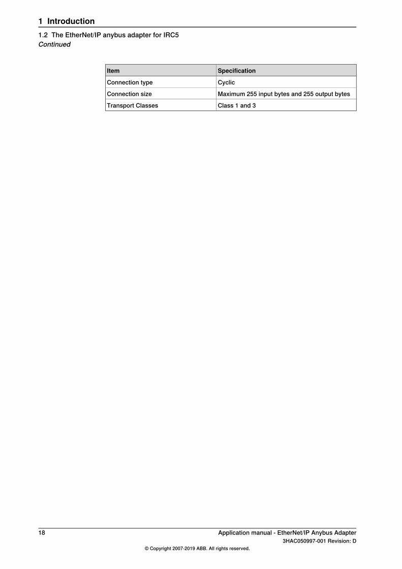
SpecificationItem
CyclicConnection type
Maximum 255 input bytes and 255 output bytesConnection size
Class 1 and 3Transport Classes
18 Application manual - EtherNet/IP Anybus Adapter3HAC050997-001 Revision: D
© Copyright 2007-2019 ABB. All rights reserved.
1 Introduction1.2 The EtherNet/IP anybus adapter for IRC5Continued

2 Hardware overview2.1 Main computer DSQC1000
ConnectionsThe I/O network is connected to the EtherNet/IP anybus adapter, DSQC 669, onthe main computer.The following figure illustrates the location of the anybus adapter in the maincomputer unit.
C
A
B
xx1300000841
Article numberDesignationDescription
3HAC046408-001DSQC1003Anybus Adapter / RS232 expansionboard
A
3HAC027652-001DSQC 669EtherNet/IP Anybus AdapterB
Ground connection for ESD braceletC
Installation of the anybus adapterFor information on how to install and replace the anybus adapter, see Productmanual - IRC5.
Continues on next pageApplication manual - EtherNet/IP Anybus Adapter 193HAC050997-001 Revision: D
© Copyright 2007-2019 ABB. All rights reserved.
2 Hardware overview2.1 Main computer DSQC1000

Illustration, EtherNet/IP anybus adapter DSQC 669
xx0700000097
Network status LEDNS
Module status LEDMS
Link/ActivityLINK
EtherNet/IP interfaceEtherNet/IP
LEDsThis section describes the LEDs of the EtherNet/IP anybus adapter.
Note
A test sequence is performed on this LED during start of the adapter.
Network status LED
DescriptionLED state
No power or no IP addressOFF
Online, one or more connections establishedGREEN
Online, no connections establishedGREEN, flashing
Duplicate IP address, fatal errorRED
One or more connections timed outRED flashing
Module status LED
DescriptionLED state
No powerOFF
Controlled by a scanner in run stateGREEN
Not configured, or scanner in idle stateGREEN flashing
Major fault (exception state, fatal error etc.)RED
Recoverable fault(s)RED flashing
Link/Activity LED
DescriptionLED state
No link, no activityOFF
Link establishedGREEN
ActivityGREEN flickering
Continues on next page20 Application manual - EtherNet/IP Anybus Adapter
3HAC050997-001 Revision: D© Copyright 2007-2019 ABB. All rights reserved.
2 Hardware overview2.1 Main computer DSQC1000Continued

Cable lengths
Permanent link lengthThe total permanent link length for COTS twisted pair systems is limited to 90 m(298 ft). The permanent link shall conform to ANSI/TIA/EIA-568-B1 according tothe EtherNet/IP Specification, see Other references on page 7.
Channel lengthThe total channel length for COTS twisted pair systems is 100 m (330 ft) includingpatch cables as defined in ANSI/TIA/EIA-568-B1 according to the EtherNet/IPSpecification, see Other references on page 7.
Application manual - EtherNet/IP Anybus Adapter 213HAC050997-001 Revision: D
© Copyright 2007-2019 ABB. All rights reserved.
2 Hardware overview2.1 Main computer DSQC1000
Continued

This page is intentionally left blank
3 Software overview3.1 Information about the anybus adapter
GeneralTo use the EtherNet/IP anybus adapter, the IRC5 controller must be installed withthe option 840-1 EtherNet/IP Anybus Adapter.The EtherNet/IP anybus adapter can be used to:
• connect the IRC5 controller to a PLC.• connect the IRC5 controller to another IRC5 controller which acts as a
scanner.
Predefined industrial networkWhen the robot system is installed with the EtherNet/IP Anybus Adapter option, apredefined industrial network with the name EtherNetIP_Anybus is created atsystem startup.
EtherNet/IP Internal Anybus DeviceWhen the robot system is installed with the EtherNet/IP Anybus Adapter option, apredefined EtherNet/IP Internal Anybus Devicewith the name EN_Internal_Anybusis created with the size of 64 input bytes and 64 output bytes.If another input or output size is required, the predefined device EN_ Internal_Anybus must be changed.
EDS fileAn Electronic Data Sheet file, EDS file, is available for the anybus adapter, matchingthe configuration of the predefined anybus internal adapter device.The EDS file, ENIP_FA.eds, for the anybus adapter can be obtained from theRobotStudio or the IRC5 controller.
• In the RobotWare installation folder in RobotStudio: ...\RobotPackages\RobotWare_RPK_<version>\utility\service\ioconfig\EtherNetIP\
• On the IRC5 Controller: <SystemName>\PRODUCTS\<RobotWare_xx.xx.xxxx>\utility\service\EDS\
Note
Navigate to the RobotWare installation folder from the RobotStudio Add-Ins tab,by right-clicking on the installed RobotWare version in the Add-Ins browser andselecting Open Package Folder.
Template I/O configuration fileA template I/O configuration file is available for the internal anybus adapter. Thefile contains names for all available inputs and outputs. The file can be loaded tothe controller, using RobotStudio or the FlexPendant, to facilitate and speed upthe configuration.
Continues on next pageApplication manual - EtherNet/IP Anybus Adapter 233HAC050997-001 Revision: D
© Copyright 2007-2019 ABB. All rights reserved.
3 Software overview3.1 Information about the anybus adapter

The I/O template configuration file, EN_Internal_Anybus.cfg, can be obtained fromthe RobotStudio or the IRC5 controller.
• In the RobotWare installation folder in RobotStudio: ...\RobotPackages\RobotWare_RPK_<version>\utility\service\ioconfig\EtherNetIP\
• On the IRC5 Controller: <SystemName>\PRODUCTS\<RobotWare_xx.xx.xxxx>\utility\service\ioconfig\EtherNetIP\
Note
Navigate to the RobotWare installation folder from the RobotStudio Add-Ins tab,by right-clicking on the installed RobotWare version in the Add-Ins browser andselecting Open Package Folder.
Input/output assemblyThe EtherNet/IP anybus adapter has the following assembly values.
ValueAssembly
150Output
100Input
0Configuration
I/O connectionCyclic I/O connection is supported and the size of the I/O connection is defined bythe EtherNet/IP internal anybus device, EN_Internal_Anybus.
Note
If the EtherNet/IP anybus adapter loses connection with its scanner, theconfigured input signals are cleared (reset to zero). The output signals are keptand are possible to change.When the connection is re-established, the scanner updates the input and outputsignals.
24 Application manual - EtherNet/IP Anybus Adapter3HAC050997-001 Revision: D
© Copyright 2007-2019 ABB. All rights reserved.
3 Software overview3.1 Information about the anybus adapterContinued
3.2 CIP routing
3.2.1 What is CIP routing?
GeneralCIP (Common Industrial Protocol) routing makes it possible to collect and viewstatus or other information from different devices placed on several CIP networksat a single or several operator stations. A CIP router allows sending messagesbetween CIP networks.
CIP standardizationCIP is standardized by ODVA. CIP devices are certified by ODVA for interoperabilityand conformance.
Application manual - EtherNet/IP Anybus Adapter 253HAC050997-001 Revision: D
© Copyright 2007-2019 ABB. All rights reserved.
3 Software overview3.2.1 What is CIP routing?

3.2.2 CIP routing for IRC5
Hardware overviewMessages are sent from one device on an EtherNet/IP network to one or severaldevices on a DeviceNet network.
Note
In IRC5 the originator of a message has to be connected on the EtherNet/IPanybus adapter network while its targets have to be on a DeviceNet network.
Illustration, exampleThe following figure illustrates an overview of the hardware.
xx1400000035
Modular EtherNet/IP DeviceA
Modules for the modular stationB
Ethernet switchC
EtherNet/IP anybus adapter, DSQC 669D
IRC5 controllerE
Continues on next page26 Application manual - EtherNet/IP Anybus Adapter
3HAC050997-001 Revision: D© Copyright 2007-2019 ABB. All rights reserved.
3 Software overview3.2.2 CIP routing for IRC5

PLCF
For information about the DeviceNet hardware, refer to Applicationmanual - DeviceNet Master/Slave.
Specification overview
SpecificationItem
EtherNet/IP to DeviceNetCIP network types
Unconnected sendRoute type
Application manual - EtherNet/IP Anybus Adapter 273HAC050997-001 Revision: D
© Copyright 2007-2019 ABB. All rights reserved.
3 Software overview3.2.2 CIP routing for IRC5
Continued

3.2.3 Information about CIP routing
GeneralThe IRC5 controller must be installed with software that supports the use of theCIP networks. To communicate through the EtherNet/IP network the EtherNet/IPAnybus Adapter option must be installed, while DeviceNet communication requiresthe DeviceNet Master/Slave option to be installed.
The function of CIP routingA message on one route can be forwarded to any of the other defined routes. Thesent message contains the destination device and port number, and from thatinformation the suitable destination route is selected. All defined CIP routes willtogether compose a virtual CIP router. During the configuration of a route the portnumber will be coupled with its network and thereby with its hardware.
ConfigurationA routing configuration requires that two or more routes are defined. One routebonds the required CIP port to a CIP network. Messages can be forwarded to anyof the networks having a CIP port defined.The following table gives descriptions of all route specific types.
DescriptionDefining...
A route identity links the required CIP port to a destination network.CIP Route
Port identityThe port identity, required by the CIP route protocol, is used in order to find adestination network. By the configuration the port identity is tied to a specificnetwork. Each network has its own unique port identity.
EDS fileFor information about the location of the EDS files, see EDS file on page 23.The EDS file contains information necessary for the CIP routing.
Example, EDS fileAn example from an EDS file that shows the configurations of the ports:
[Port]
Port1 =
TCP,$ port type name
"TCP/IP",$ name of port
"20 F5 24 01", $ instance one of the TCP/IP interface $ object
2;$ port number
LimitationsCIP routing has the following limitations:
DescriptionItem
A maximum of 5 routes can be defined.Max. routes
Continues on next page28 Application manual - EtherNet/IP Anybus Adapter
3HAC050997-001 Revision: D© Copyright 2007-2019 ABB. All rights reserved.
3 Software overview3.2.3 Information about CIP routing

DescriptionItem
Only unconnected send service routing is supported.Unconnected send connec-tion
This is the only supported connection type. In order to seeor use a DeviceNet device it has to allow Explicit messageconnection.
Explicit message connection
Unsupported connection type.I/O message connection
The router cannot act as an intermediate hop, that is, therouter cannot forward a message to its target when it has togo through another router.
Single hop
An EtherNet/IP route only has server capability. A server willonly respond to a received request.
EtherNet/IP
A DeviceNet route only has client capability. A client will is-sue a request and expects an answer to its request.
DeviceNet
Application manual - EtherNet/IP Anybus Adapter 293HAC050997-001 Revision: D
© Copyright 2007-2019 ABB. All rights reserved.
3 Software overview3.2.3 Information about CIP routing
Continued

This page is intentionally left blank
4 Configuring the anybus adapter4.1 Recommended working procedure
GeneralThis section describes the recommended working procedure when installing andconfiguring the EtherNet/IP anybus adapter. The working procedure helps tounderstand the dependencies between the different steps.When the IRC5 controller with the EtherNet/IP anybus adapter is connected to anexternal scanner, the IRC5 controller acts as an adapter on the EtherNet/IP network.
Basic stepsUse this procedure to install and configure the EtherNet/IP anybus adapter.
SeeAction
Configuring the anybus adapter onpage 32
Create and configure the anybus adapterin the IRC5 controller using RobotStudioor the FlexPendant.
1
Configuring the external scanner onpage 34
Configure the external scanner using thevendor specific configuration tool.
2
Additional configuration
SeeAction
Configuring CIP routing on page 35CIP routing configuration.
Application manual - EtherNet/IP Anybus Adapter 313HAC050997-001 Revision: D
© Copyright 2007-2019 ABB. All rights reserved.
4 Configuring the anybus adapter4.1 Recommended working procedure
4.2 Configuring the anybus adapter
GeneralA device is required in order to be able to create the signals attached to the anybusadapter.The size of the anybus adapter determines how many signals that can be attached.
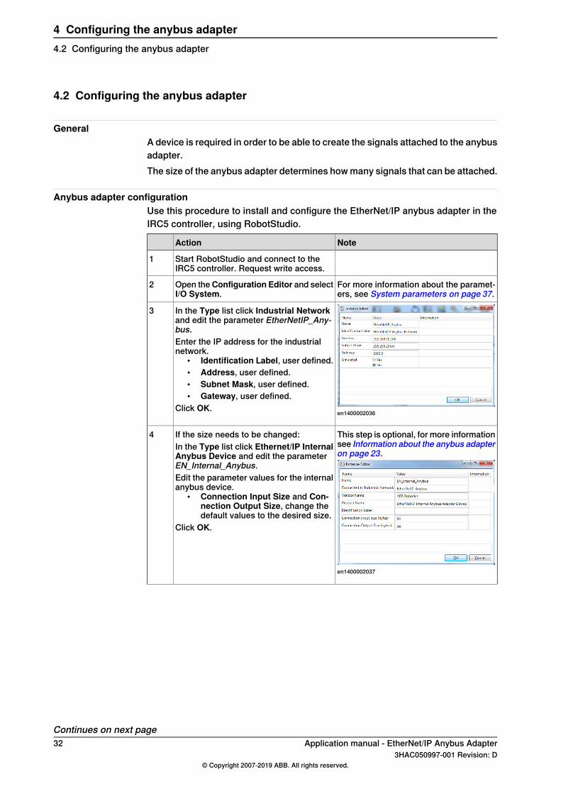
Anybus adapter configurationUse this procedure to install and configure the EtherNet/IP anybus adapter in theIRC5 controller, using RobotStudio.
NoteAction
Start RobotStudio and connect to theIRC5 controller. Request write access.
1
For more information about the paramet-ers, see System parameters on page 37.
Open theConfiguration Editor and selectI/O System.
2
en1400002036
In the Type list click Industrial Networkand edit the parameter EtherNetIP_Any-bus.Enter the IP address for the industrialnetwork.
• Identification Label, user defined.• Address, user defined.• Subnet Mask, user defined.• Gateway, user defined.
Click OK.
3
This step is optional, for more informationsee Information about the anybus adapteron page 23.
en1400002037
If the size needs to be changed:In the Type list click Ethernet/IP InternalAnybus Device and edit the parameterEN_Internal_Anybus.Edit the parameter values for the internalanybus device.
• Connection Input Size and Con-nection Output Size, change thedefault values to the desired size.
Click OK.
4
Continues on next page32 Application manual - EtherNet/IP Anybus Adapter
3HAC050997-001 Revision: D© Copyright 2007-2019 ABB. All rights reserved.
4 Configuring the anybus adapter4.2 Configuring the anybus adapter

NoteAction
en1400002038
In the Type list click Signal.Add I/O signals for the EN_Internal_Any-bus device.
5
Restart the controller.6Now the IRC5 controller is ready to becontacted from an EtherNet/IP scanner.
Viewing the MAC addressAfter the configuration, it is possible to view the MAC address of the EtherNet/IPanybus adapter on FlexPendant in one of the following ways:
Using the Industrial Networks view.
NoteAction
The list of most common I/O signals isdisplayed.
In the ABB menu, tap Inputs and Out-puts.
1
The list of available industrial networks isdisplayed.
Tap View and select Industrial Networks.2
Tap EtherNetIP_Anybus.3
The MAC address of EtherNet/IP anybusadapter is displayed along with the otherdetails.
Tap I/O Device Identification.4
Using the I/O Devices view.
NoteAction
The list of most common I/O signals isdisplayed.
In the ABB menu, tap Inputs and Out-puts.
1
The list of available I/Odevices is dis-played.
Tap View and select I/O Devices.2
Tap the I/O device created to Ethernet/IPanybus adapter.
3
The MAC address of EtherNet/IP anybusadapter is displayed along with the otherdetails.
TapActions and select I/O Device Identi-fication.
4
Application manual - EtherNet/IP Anybus Adapter 333HAC050997-001 Revision: D
© Copyright 2007-2019 ABB. All rights reserved.
4 Configuring the anybus adapter4.2 Configuring the anybus adapter
Continued

4.3 Configuring the external scanner
GeneralThe external scanner is configured by using the vendor specific configuration toolthat is delivered, or bought, together with the scanner.The tool is used to specify all the devices in the EtherNet/IP network. One of thedevices is the anybus adapter of the IRC5 controller. If it is necessary to importthe EDS file that describes the internal adapter device to configure the anybusadapter device in the vendor specific configuration, see EDS file on page 23.
External scanner configurationThis procedure describes the general steps that needs to be performed whenconfiguring an external scanner, independent of which tool is used.
Action
Use the external master configuration tool to:• Specify the address of the external EtherNet/IP scanner.• Import the EDS files for the internal adapter device and all other types of
devices in the network.• Add the IRC5 controller anybus adapter device and set the same EtherNet/IP
address as in the IRC5 controller.• Add any other I/O devices into the industrial network structure.• Add signals for all I/O devices including the anybus adapter device.
1
34 Application manual - EtherNet/IP Anybus Adapter3HAC050997-001 Revision: D
© Copyright 2007-2019 ABB. All rights reserved.
4 Configuring the anybus adapter4.3 Configuring the external scanner

4.4 Configuring CIP routing
IntroductionThe following figure illustrates an example of how to use CIP routing, and showsan IRC5 controller with connections to the networks. For each of the CIP hardwaredevices (C and E), route parameters have to be defined.The route parameters are added to the I/O configuration of the IRC5 controller.
ExampleIn this example the possible route is :
• From Port ID: 2 to Port ID: 3, and further to equipment on the DeviceNetnetwork.
xx0700000393
PLCA
EtherNet/IP scannerB
EtherNet/IP anybus adapter with Port ID: 2.C
IRC5 controllerD
DeviceNet master with Port ID: 3.E
User equipment on DeviceNet, for example arc welding or spot welding.F
Note
The maximum number of ports depends on total number of DeviceNet channels- that is, 2 + number of DeviceNet channels, see Port ID on page 46.
Configuring the CIP routesUse this procedure to add CIP routes, using RobotStudio.
NoteAction
Start RobotStudio and connect to theIRC5 controller. Request write access.
1
For more information about the paramet-ers, see System parameters on page 37.
Open theConfiguration Editor and selectI/O System.
2
Continues on next pageApplication manual - EtherNet/IP Anybus Adapter 353HAC050997-001 Revision: D
© Copyright 2007-2019 ABB. All rights reserved.
4 Configuring the anybus adapter4.4 Configuring CIP routing

NoteAction
In the Type list click Route, right-click inthe workspace and select New Route.
3
Add a route to the EtherNet/IP anybusadapter.
• Name, user defined.• Industrial Network, shall be Ether-
NetIP_Anybus.• Port ID, user defined.
Click OK.
en1400002325
In the Type list click Route, right-click inthe workspace and select New Route.Add routes to the DeviceNet network.
• Name, user defined.• Industrial Network, select the
DeviceNet network.• Port ID, user defined.
Click OK.
4
Restart the controller.5
36 Application manual - EtherNet/IP Anybus Adapter3HAC050997-001 Revision: D
© Copyright 2007-2019 ABB. All rights reserved.
4 Configuring the anybus adapter4.4 Configuring CIP routingContinued
5 System parameters5.1 Introduction
About the system parametersThere are both EtherNet/IP specific parameters and more general parameters. Thischapter describes all EtherNet/IP specific system parameters. The parameters aredivided into the type they belong to.For information about other system parameters, see Technical referencemanual - System parameters.
EtherNet/IP system parameters
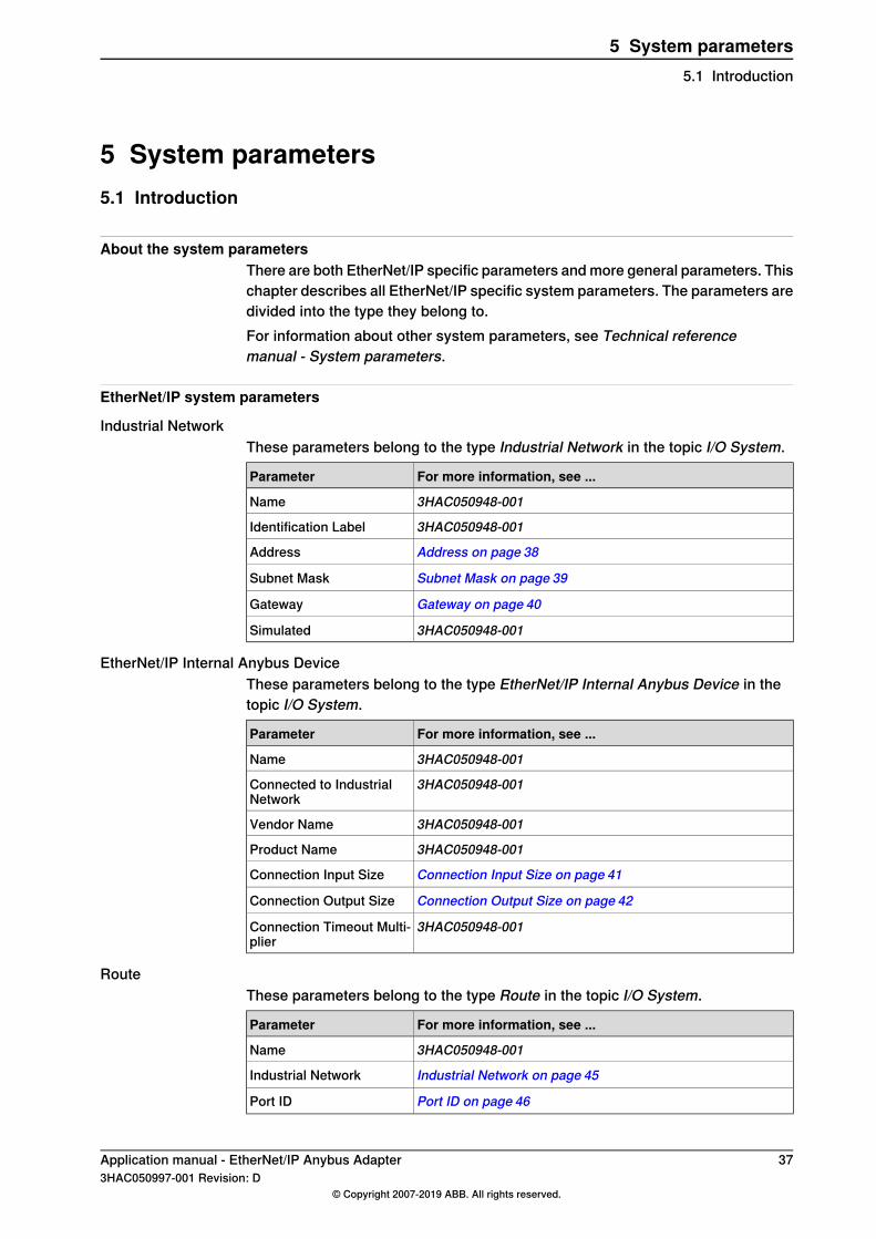
Industrial NetworkThese parameters belong to the type Industrial Network in the topic I/O System.
For more information, see ...Parameter
3HAC050948-001Name
3HAC050948-001Identification Label
Address on page 38Address
Subnet Mask on page 39Subnet Mask
Gateway on page 40Gateway
3HAC050948-001Simulated
EtherNet/IP Internal Anybus DeviceThese parameters belong to the type EtherNet/IP Internal Anybus Device in thetopic I/O System.
For more information, see ...Parameter
3HAC050948-001Name
3HAC050948-001Connected to IndustrialNetwork
3HAC050948-001Vendor Name
3HAC050948-001Product Name
Connection Input Size on page 41Connection Input Size
Connection Output Size on page 42Connection Output Size
3HAC050948-001Connection Timeout Multi-plier
RouteThese parameters belong to the type Route in the topic I/O System.
For more information, see ...Parameter
3HAC050948-001Name
Industrial Network on page 45Industrial Network
Port ID on page 46Port ID
Application manual - EtherNet/IP Anybus Adapter 373HAC050997-001 Revision: D
© Copyright 2007-2019 ABB. All rights reserved.
5 System parameters5.1 Introduction

5.2 Type Industrial Network
5.2.1 Address
ParentAddress belongs to the type Industrial Network, in the topic I/O System.
DescriptionThe parameterAddress specifies the IP address of the EtherNet/IP anybus adapteron the network. This IP address is used by an external scanner to set up aconnection to the anybus adapter.
UsageThe parameter Address is used to set the IP address of the IRC5 controller on theused network interface (decided with the Connection parameter).
PrerequisitesThe option EtherNet/IP Anybus Adapter must be installed.
Default value0.0.0.0
Allowed values0.0.0.0 - 255.255.255.255
38 Application manual - EtherNet/IP Anybus Adapter3HAC050997-001 Revision: D
© Copyright 2007-2019 ABB. All rights reserved.
5 System parameters5.2.1 AddressEtherNet/IP Anybus Adapter

5.2.2 Subnet Mask
ParentSubnet Mask belongs to the type Industrial Network, in the topic I/O System.
DescriptionThe parameter Subnet Mask is used to determine what subnet the IP addressbelongs to.
UsageThe parameter Subnet Mask is used to divide the network into logical subnets.
PrerequisitesThe option EtherNet/IP Anybus Adapter must be installed.
Default valueThe default value is an empty string.
Allowed values0.0.0.0 - 255.255.255.255
Application manual - EtherNet/IP Anybus Adapter 393HAC050997-001 Revision: D
© Copyright 2007-2019 ABB. All rights reserved.
5 System parameters5.2.2 Subnet Mask
EtherNet/IP Anybus Adapter

5.2.3 Gateway
ParentGateway belongs to the type Industrial Network, in the topic I/O System.
DescriptionThe parameter Gateway specifies the node on the network that serves as anentrance to another network.
UsageUse this parameter if the EtherNet/IP traffic needs to be routed to another network.The parameter value is the address to a physical gateway on the EtherNet/IPnetwork.
PrerequisitesThe option EtherNet/IP Anybus Adapter must be installed.
Default valueEmpty
Allowed values0.0.0.0 - 255.255.255.255
40 Application manual - EtherNet/IP Anybus Adapter3HAC050997-001 Revision: D
© Copyright 2007-2019 ABB. All rights reserved.
5 System parameters5.2.3 GatewayEtherNet/IP Anybus Adapter
5.3 Type EtherNet/IP Internal Anybus Device
5.3.1 Connection Input Size
ParentConnection Input Size belongs to the type EtherNet/IP Internal Anybus Device, inthe topic I/O System.
DescriptionConnection Input Size defines the data size in bytes for the input area receivedfrom the connected EtherNet/IP scanner.
UsageConnection Input Size is an EtherNet/IP specific parameter.
PrerequisitesThe option EtherNet/IP Anybus Adapter must be installed.
Default valueThe default value is 64 bytes (512 signal bits).
Allowed valuesAllowed values are the integers 0-255 (0-2040 signal bits), specifying the data sizein bytes.
Application manual - EtherNet/IP Anybus Adapter 413HAC050997-001 Revision: D
© Copyright 2007-2019 ABB. All rights reserved.
5 System parameters5.3.1 Connection Input Size

5.3.2 Connection Output Size
ParentConnection Output Size belongs to the type EtherNet/IP Internal Anybus Device,in the topic I/O System.
DescriptionConnection Output Size defines the data size in bytes for the output area sent tothe connected EtherNet/IP scanner.
UsageConnection Output Size is an EtherNet/IP specific parameter.
PrerequisitesThe option EtherNet/IP Anybus Adapter must be installed.
Default valueThe default value is 64 bytes (512 signal bits).
Allowed valuesAllowed values are the integers 0-255 (0-2040 signal bits), specifying the data sizein bytes.
42 Application manual - EtherNet/IP Anybus Adapter3HAC050997-001 Revision: D
© Copyright 2007-2019 ABB. All rights reserved.
5 System parameters5.3.2 Connection Output Size
5.3.3 Connection Timeout Multiplier
ParentConnection Timeout Multiplier belongs to the type Device, in the topic I/O System.
DescriptionConnection Timeout Multiplier specifies the multiplier applied to the expectedpacket rate value to derive the value for the Inactivity/Watchdog Timer.
UsageThe Connection Timeout Multiplier is a number among 4, 8, 16, 32, 64, 128, 256.It is used together with RPI to calculate the timeout on connections. RPI multipliedby Connection Timeout Multiplier gives the maximum time before dropping theconnection.
Note
For the IRB 14000 and IRB 14050 robots this parameter may have to be tuneddepending on your network setup.
Allowed valuesAllowed values are 4, 8, 16, 32, 64, 128, 256, 512.Default value is 4.
Application manual - EtherNet/IP Anybus Adapter 433HAC050997-001 Revision: D
© Copyright 2007-2019 ABB. All rights reserved.
5 System parameters5.3.3 Connection Timeout Multiplier
EtherNet/IP Scanner/Adapter
5.4 Type Route
5.4.1 Name
ParentName belongs to the type Route, in the topic I/O System.
DescriptionThe parameter Name specifies the name of the route.
UsageName specifies a route, to which the route messages can be received or sent to.
PrerequisitesThe options EtherNet/IP Anybus Adapter and DeviceNet Master/Slave must beinstalled.
Default valueThe default value is an empty string
Allowed valuesThe value can be a string of characters.
44 Application manual - EtherNet/IP Anybus Adapter3HAC050997-001 Revision: D
© Copyright 2007-2019 ABB. All rights reserved.
5 System parameters5.4.1 Name

5.4.2 Industrial Network
ParentIndustrial Network belongs to the type Route, in the topic I/O System.
DescriptionThe parameter Industrial Network specifies the name of the industrial network.
UsageIndustrial Network shows which network is associated to a certain port.
PrerequisitesThe options EtherNet/IP Anybus Adapter and DeviceNet Master/Slave must beinstalled.
Default valueThe default value is an empty string.
Allowed valuesThe value can be any defined I/O network name.
Application manual - EtherNet/IP Anybus Adapter 453HAC050997-001 Revision: D
© Copyright 2007-2019 ABB. All rights reserved.
5 System parameters5.4.2 Industrial Network

5.4.3 Port ID
ParentPort ID belongs to the type Route, in the topic I/O System.
DescriptionThe parameter Port ID specifies the port of the I/O network.
UsagePort ID is used in the CIP routing path.
PrerequisitesThe options EtherNet/IP Anybus Adapter and DeviceNet Master/Slave must beinstalled.
Default valueThe default value is 2.
Allowed valuesThe value can be from 2 to 6.
Note
Value 1 is reserved and is not allowed to use.
46 Application manual - EtherNet/IP Anybus Adapter3HAC050997-001 Revision: D
© Copyright 2007-2019 ABB. All rights reserved.
5 System parameters5.4.3 Port ID
IndexAAddress, 38
Ccable length, 21channel length, 21CIP, 15CIP router, 25CIP routing, 25
CIP port, 28configuration, 28, 35function, 28limitations, 28port identity, 28
Common Industrial Protocol, 25configuration, CIP routing, 35ControlNet, 15
DDeviceNet, 15DSQC 669, 16, 20
EEDS file, 15, 23, 28EtherNet/IP, 15
data, 15specification, 17standardization, 15
EtherNet/IP anybus adapter, 16
GGateway, 40
II/O connection, 24
cyclic, 24Internal Anybus Device, 23
LLED, 20
link/activity, 20module status, 20network status, 20test, 20
MMAC address, 33
Nnetwork security, 12
OODVA, 15
Ppredefined industrial network, 23
Ssafety, 11Subnet Mask, 39system parameters
Address, 38Connection Timeout Multiplier, 43Gateway, 40Industrial Network, 45Name, 44Port ID, 46Subnet Mask, 39
Ttemplate I/O configuration file, 23topic I/O System
Industrial Network, 23, 37Internal anybus device, 23Internal Anybus device, 37Route, 37
Application manual - EtherNet/IP Anybus Adapter 473HAC050997-001 Revision: D
© Copyright 2007-2019 ABB. All rights reserved.
Index


ABB AB, RoboticsRobotics and MotionS-721 68 VÄSTERÅS, SwedenTelephone +46 (0) 21 344 400
ABB AS, RoboticsRobotics and MotionNordlysvegen 7, N-4340 BRYNE, NorwayBox 265, N-4349 BRYNE, NorwayTelephone: +47 22 87 2000
ABB Engineering (Shanghai) Ltd.Robotics and MotionNo. 4528 Kangxin HighwayPuDong DistrictSHANGHAI 201319, ChinaTelephone: +86 21 6105 6666
ABB Inc.Robotics and Motion1250 Brown RoadAuburn Hills, MI 48326USATelephone: +1 248 391 9000
abb.com/robotics
3HAC050997-001,Rev
D,en
© Copyright 2007-2019 ABB. All rights reserved.Specifications subject to change without notice.