s&c tripsaver ii · inrush-restraint feature the tripsaver ii cutout-mounted recloser has a...
TRANSCRIPT

S&C TripSaver ® IICutout-Mounted Recloser
For enhanced lateral circuit protectionat 15 kV and 25 kV

2
Conventional lateral circuit protection requires some concessionsMore than 90% of transient faults on overhead distribution circuits occur on laterals. Over the years, utilities have dealt with lateral protection a couple of ways.
Some utilities use a “fuse-blowing” philosophy: The substation feeder breaker is properly coordinated with the lateral fuse so the fuse will clear any downstream fault within its rating . . . not the breaker.
The problem: Customers on the lateral experience sustained service interruption—even for a transient fault—as shown in Figure 1. And the utility must deal with the high cost of service calls to replace lateral fuses.
Feeder breaker
Lateral fuse
Transient fault
Figure 1. “Fuse-blowing” philosophy.
Other utilities use a “fuse-saving” philosophy: The first trip of the substation feeder breaker is intentionally miscoordinated so that the breaker operates faster than the lateral fuse to clear a fault downstream of the lateral fuse. The second trip of the breaker is slower so that if the fault is still present, the lateral fuse will operate to clear it.
The problem: All customers on the feeder experience a momentary interruption for all faults—as shown in Figure 2.
Figure 2. “Fuse-saving” philosophy.
TripSaver II recloser provides better lateral protectionS&C’s TripSaver II Cutout-Mounted Recloser eliminates these problems. It’s ideally suited for protection of laterals that experience frequent transient faults. This self-powered, electronically controlled, single-phase vacuum fault interrupter is available for installation in new or existing current-production (“-R10” or “-R11”) S&C-provided Type XS Fuse Cutout Mountings.
The TripSaver II recloser eliminates the sustained interruption that results when the lateral fuse oper-ates in response to a transient fault. Utilities using a “fuse-blowing” strategy will see an improvement in SAIFI without sacrificing MAIFI.
And the TripSaver II recloser eliminates the momentary interruption on the feeder in instances where the breaker is tripped to save the lateral fuse during a transient fault. Utilities using a “fuse-saving” strategy will see an improvement in MAIFI without sacrificing SAIFI.
Introducing S&C’s TripSaver II Cutout-Mounted Recloser:
A better solution for overhead lateral circuit protection at 15 kV and 25 kV
Feeder breaker
Lateral fuse
Transient or persistent fault

3
Table 1. Comparison of Lateral Protective Devices
Feature/Benefit Single-Phase Hydraulic Recloser
Dropout-Style Electronic
Sectionalizer
TripSaver II Recloser
Easy to install Low initial price Low installation cost Fault-interrupting capability Easy to reset Electronic control No bypass switch required Light weight compared to oil reclosers Fits in cutout mounting No momentary interruption on the main feeder for lateral faults
The TripSaver II Cutout-Mounted Recloser has been tested to, and is in compliance with, IEEE Standards C37.60-2012 and C37.41-2008 and IEC Standard 62271-111. TripSaver II units are manufactured in accordance with a quality system certified to ISO 9001:2000.
As shown Table 1, the TripSaver II recloser offers a number of advantages over traditional lateral protective devices.
4
TripSaver II recloser’s operating sequenceThe TripSaver II Cutout-Mounted Recloser supports up to three reclosing operations (four tripping operations in total) before it drops open. Multiple varieties of time-current characteristic (TCC) curves are available. The duration of the open interval between tripping operations is user configurable. It has a range of from 0.5 seconds to 5 seconds.
An option with an extended open interval of up to 90 seconds is also available.
The vacuum interrupter resets two seconds after the TripSaver II unit drops open. The operator can then manually close the TripSaver II device back into the mounting after the repair has been made.
In instances in which a transient fault is cleared before the TripSaver II device reaches the end of its operating sequence, the recloser will revert to its first TCC curve, after its sequence reset timer expires. The sequence reset time is also user configurable, and it has a range from 0.5 seconds to 1000 seconds.
How the TripSaver II recloser works for a transient faultConsider a transient fault downstream of the TripSaver II Cutout-Mounted Recloser, as shown in Figure 3.
TripSaver II
Feeder breaker
Transient fault
Figure 3. A downstream transient fault.
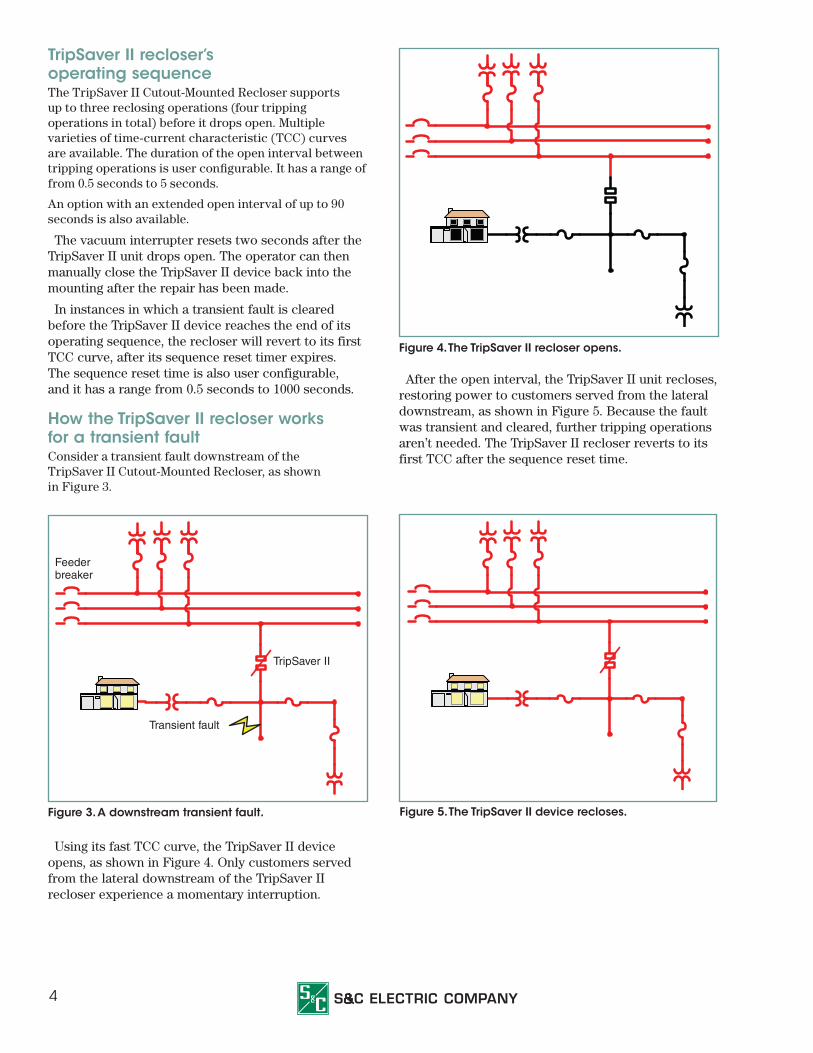
Using its fast TCC curve, the TripSaver II device opens, as shown in Figure 4. Only customers served from the lateral downstream of the TripSaver II recloser experience a momentary interruption.
Figure 4. The TripSaver II recloser opens.
After the open interval, the TripSaver II unit recloses, restoring power to customers served from the lateral downstream, as shown in Figure 5. Because the fault was transient and cleared, further tripping operations aren’t needed. The TripSaver II recloser reverts to its first TCC after the sequence reset time.
Figure 5. The TripSaver II device recloses.

5
How the TripSaver II recloser works for a persistent fault Consider a persistent fault downstream of the TripSaver II unit, as shown in Figure 6.
As before, using its fast TCC curve, the TripSaver II recloser opens, as shown in Figure 7. Again, only customers served from the lateral downstream of the device experience a momentary interruption. The TripSaver II device then recloses, as shown in Figure 8.
Because the fault is persistent, the TripSaver II Cutout-Mounted Recloser performs further tripping operations per the specified TCC curves. For utilities using a “fuse-saving” philosophy, the TripSaver II device drops open at the end of its operating sequence in the same manner as a standard fuse cutout—providing visual indication that the faulted lateral has been isolated, as shown in Figure 9. The vacuum interrupter resets two seconds after the TripSaver II recloser drops open. The unit may then be manually closed back into the mounting by the operator once the fault has been repaired.
Figure 6. A persistent-fault scenario. Figure 8. The TripSaver II unit recloses.
Figure 7. The TripSaver II unit opens. Figure 9. The TripSaver II recloser drops open.
Persistent fault
TripSaver II unit
Feeder breaker
Persistent fault Persistent fault

6
Ice-Breaking CapabilityThe TripSaver II recloser is capable of dropping open under ¾-inch (20-mm) ice formation.
Sectionalizing FeatureThe TripSaver II device features a sectionalizing mode in both 4-kA and 6.3-kA-rated models. When enabled, the recloser will operate as a sectionalizer over a user-specified range of fault currents when the source-side circuit breaker or recloser trips faster than the TripSaver II recloser does. It counts the number of operations of the source-side circuit breaker or recloser and drops open after a user-specified number of counts.
Inrush-Restraint FeatureThe TripSaver II Cutout-Mounted Recloser has a novel magnetizing inrush-restraint feature that is always on, measuring second-harmonic current to distinguish fault current from inrush current. If inrush current is detected, the TripSaver II recloser will not trip. The inrush-restraint feature facilitates lower minimum pickup currents down to 5 amperes.
Local Manual Open FeatureThe new Local Manual Open feature removes the requirement to use the Loadbuster®—The S&C Loadbreak Tool for loadbreaking by providing a manual operation sequence that commands the TripSaver II device to open the vacuum interrupter contacts and drop open.
Construction and Features
A Birdproof-design insulator—Higher insulation characteristics than ANSI distribution-cutout standards. Porcelain insulator shown; a composite-polymer silicone insulator also is available. NEMA Type B and S&C extended mounting brackets are available.
B Parallel-groove connector—Tin-plated cast red brass. For ease of connection, the recloser accommodates two conductors, even of unlike size.
C Attachment hooks for Loadbuster®—S&C’s Loadbreak Tool—The hooks also guide the TripSaver II recloser during manual closing.
D Upper contact—Silver-to-silver; a stainless-steel spring provides high contact pressure.
E Bumper and Retainer—Spring-loaded retainer and bumper dampen impact on closing, reducing the possibility of bounce back.
F Vacuum fault interrupter—The interrupter is contained inside the upper housing.
G Trunnion—High-strength cast bronze, silver plated. Surfaces around the trunnion bear on broad hinge surfaces to keep the TripSaver II recloser in alignment during closing. Its special shape facilitates easy removal and reduces vibration.
H Lower contacts—Silver-to-silver; the contacts provide a dual current path, independent of the hinge pivot.
I Mode selector lever—For selecting automatic reclosing or nonreclosing operation. In nonreclosing mode, the TripSaver II recloser will operate “one shot to lockout. ” The lever is suitable for use when crews are working downstream of the TripSaver II recloser.
J Liquid-crystal display screen—displays TripSaver II recloser status. Six languages are supported. Display items are user configurable.
B
J
F
EC
A
H
G
D
I
7
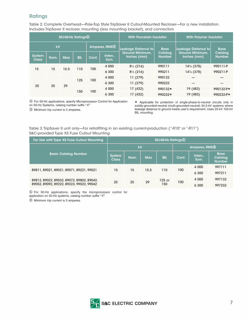
① For 50-Hz applications, specify Microprocessor Control for Application on 50-Hz Systems, catalog number suffix “-F.”② Minimum trip current is 5 amperes.
★ Applicable for protection of single-phase-to-neutral circuits only in solidly-grounded-neutral (multi-grounded-neutral) 34.5-kV systems where leakage distance to ground meets user’s requirement. Uses 25-kV 150-kV BIL mounting.
Ratings
Table 2. Complete Overhead—Pole-Top Style TripSaver II Cutout-Mounted Recloser—For a new installation. Includes TripSaver II recloser, mounting (less mounting bracket), and connectors
50/60-Hz Ratings① With Porcelain Insulator With Polymer Insulator
kV Amperes, RMS② Leakage Distance to
Ground Minimum, Inches (mm)
BaseCatalog Number
Leakage Distance to Ground Minimum,
Inches (mm)
BaseCatalog NumberSystem
Class Nom. Max BIL Cont. Interr.,Sym.
15 15 15.5 110 1004 000 8½ (216) 990111 14⅞ (378) 990111-P
6 300 8½ (216) 990211 14⅞ (378) 990211-P
25 25 29
125 1004 000 11 (279) 990122 — —
6 300 11 (279) 990222 — —
150 1004 000 17 (432) 990132★ 19 (483) 990132-P★
6 300 17 (432) 990232★ 19 (483) 990232-P★
Table 3. TripSaver II unit only—For retrofitting in an existing current-production (“-R10” or “-R11”) S&C-provided Type XS Fuse Cutout Mounting
For Use with Type XS Fuse Cutout Mounting 50/60-Hz Ratings①
Basic Catalog Number
kV Amperes, RMS②
SystemClass Nom. Max BIL Cont. Interr.,
Sym.
BaseCatalogNumber
89811, 89021, 89031, 89071, 89221, 99021 15 15 15.5 110 1004 000 997111
6 300 997211
89812, 89022, 89032, 89072, 89802, 89042, 89052, 89092, 89222, 89223, 99022, 99042 25 25 29 125 or
150 1004 000 997132
6 300 997232
① For 50-Hz applications, specify the microprocessor control for application on 50-Hz systems, catalog number suffix “-F.”② Minimum trip current is 5 amperes.

8
Table 4. Mounting Bracket Options—For Overhead—Pole-Top Style TripSaver II Models
Item Add Catalog Number Suffix
S&C extended mounting bracket, for crossarm, pole, or wall mounting -B
NEMA Type B mounting bracket, for crossarm mounting - C
Table 6. List of Available CurvesMicroprocessor Recloser
Cooper Microprocessor Form 4,5,6,FX
Name Definition
S&C 101 Cooper 101
S&C 102 Cooper 102
S&C 103 Cooper 103
S&C 104 Cooper 104
S&C 105 Cooper 105
S&C 106 Cooper 106
S&C 107 Cooper 107
S&C 111 Cooper 111
S&C 112 Cooper 112
S&C 113 Cooper 113
S&C 115 Cooper 115
S&C 116 Cooper 116
S&C 117 Cooper 117
S&C 118 Cooper 118
S&C 119 Cooper 119
S&C 120 Cooper 120
S&C 132 Cooper 132
S&C 133 Cooper 133
S&C 134 Cooper 134
S&C 135 Cooper 135
S&C 137 Cooper 137
S&C 138 Cooper 138
S&C 142 Cooper 142
S&C 151 Cooper 151
S&C 161 Cooper 161
S&C 162 Cooper 162
S&C 163 Cooper 163
S&C 165 Cooper 165
S&C 201 Cooper 201
S&C 202 Cooper 202
SEL 351R/651R Recloser Control
Name Definition
SEL U1 SEL U1 Moderately Inverse
SEL U2 SEL U2 Inverse
SEL U3 SEL U3 Very Inverse
SEL U4 SEL U4 Extremely Inverse
SEL U5 SEL U5 Short-Time Inverse
SEL C1 SEL C1 Standard Inverse
SEL C2 SEL C2 Very Inverse
SEL C3 SEL C3 Extremely Inverse
SEL C4 SEL C4 Long-Time Inverse
SEL C5 SEL C5 Short-Time Inverse
ABB DPU 2000R Recloser Control
Name Definition
ABB INV ABB Inverse
ABB VI ABB Very Inverse
ABB EI ABB Extremely Inverse
ABB STI ABB Short-Time Inverse
ABB STEI ABB Short-Time Extremely Inverse
IEC Standard Curve
Name Definition
IEC SI IEC Standard Inverse
IEC VI IEC Very Inverse
IEC EI IEC Extremely Inverse
IEEE Standard Curve
Name Definition
IEEE EI IEEE Extremely Inverse
IEEE MI IEEE Moderately Inverse
IEEE VI IEEE Very Inverse
Table 5. Other Options
Item Add Catalog Number Suffix
Extended Open Interval -O

9
Fuse LinkAmpere Rating
K-Speed T-Speed QR KS NE (N-Speed McGraw Edison)
NK (N-Speed Kearney)
6K 6T 3QR 10KS 25NE 25NK
8K 8T 5QR 15KS 30NE 30NK
10K 10T 7QR 20KS 40NE 40NK
12K 12T 8QR 25KS 50NE 50NK
15K 15T 10QR 30KS 60NE 65NK
20K 20T 15QR 40KS 75NE 80NK
25K 25T 20QR 50KS 85NE 100NK
30K 30T 25QR 65KS 100NE
40K 40T 30QR 80KS
50K 50T 40QR 100KS
65K 65T 50QR
80K 80T 60QR
100K 100T 75QR
100QR
Cooper (McGraw-Edison) Hydraulic RecloserType H
Name Definition Coil Rating
H-A Type H, A curve 5A, 10A, 15A, 25A, 35A, 50A
H-B Type H, B curve 5A, 10A, 15A, 25A, 35A, 50A
H-C Type H, C curve 5A, 10A, 15A, 25A, 35A, 50A
Type 4H, V4H
Name Definition Coil Rating
(V)4H-A Type 4H or Type V4H, A curve
5A, 10A, 15A, 25A, 35A, 50A,
70A, 100A
(V)4H-B Type 4H or Type V4H, B curve
5A, 10A, 15A, 25A, 35A, 50A,
70A, 100A
(V)4H-C Type 4H or Type V4H, C curve
5A, 10A, 15A, 25A, 35A, 50A,
70A, 100A
Type L
Name Definition Coil Rating
L-A Type L, A curve 25A, 35A, 50A, 70A, 100A
L-B Type L, B curve 25A, 35A, 50A, 70A, 100A
L-C Type L, C curve 25A, 35A, 50A, 70A, 100A
L-D Type L, D curve 25A, 35A, 50A, 70A, 100A
Type V4L, V4E
Name Definition Coil Rating
V4L(E)-A Type V4L or Type V4E, A curve
15A, 25A, 35A, 50A, 70A, 100A
V4L(E)-B Type V4L or Type V4E, B curve
15A, 25A, 35A, 50A, 70A, 100A
V4L(E)-C Type V4L or Type V4E, C curve
15A, 25A, 35A, 50A, 70A, 100A
V4L(E)-D Type V4L or Type V4E, D curve
15A, 25A, 35A, 50A, 70A, 100A
Type E
Name Definition Coil Rating
E-A Type E, A curve5A, 10A, 15A, 25A, 35A, 50A,
70A, 100A
E-B Type E, B curve5A, 10A, 15A, 25A, 35A, 50A,
70A, 100A
E-C Type E, C curve5A, 10A, 15A, 25A, 35A, 50A,
70A, 100A
E-D Type E, D curve5A, 10A, 15A, 25A, 35A, 50A,
70A, 100A
Type 4E
Name Definition Coil Rating
4E-A Type 4E, A curve 50A, 70A, 100A
4E-B Type 4E, B curve 50A, 70A, 100A
4E-C Type 4E, C curve 50A, 70A, 100A
4E-D Type 4E, D curve 50A, 70A, 100A
Table 6. List of Available Curves—continued

10
User Interface
User configurable LCD screen and mode selector lever. Springs help guide the lever to the desired position. Colored labels provide visual confirmation. “NR” mode
engaged, as shown: upper label is completely exposed and lower labels (down position) are aligned.
Mode-selector leverLCD screen
Table 7. Available LCD Screen ItemsScreen Name Description
Primary Normal Screen
Four operating parameters are displayed: Vacuum Interrupter Status (Open or Closed); Mode Selector Status (Auto, NR, or R-NR); Overload Indicator at the bottom left corner (Symbol “X”); and Service Soon Indicator at the bottom right corner (Symbol “•”). The Overload Indicator will appear when a TripSaver II device has dropped open due to an overload. The Service Soon Indicator will appear when the vacuum interrupter reaches 10% of its remaining contact wear.
Secondary Normal Screen
Three operating parameters are displayed: Vacuum Interrupter Status at the upper left corner (Symbol “O” for Open, Symbol “I” for Closed); Number of Open Operations at the upper right corner; and Remaining Contact Wear in bar chart format at the bottom of the screen. (A full blue bar indicates 100% remaining contact wear. The blue bar shortens in length leftward as remaining contact wear decreases.)
Blue Screen
A blue screen is displayed.
Load Current
The load current in primary amperes is displayed.
Last Fault Magnitude
The fundamental-frequency magnitude of the last fault current in primary amperes, measured just before the opening of the vacuum interrupter, is displayed.
Vacuum Interrupter Status
The state of the vacuum interrupter: either OPEN or CLOSED is displayed.
Mode Selector Status
The mode of operation: either AUTO, NR, or R-NR is displayed.
11
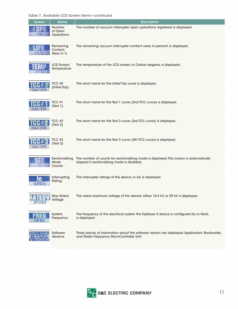
Screen Name Description
Number of Open Operations
The number of vacuum interrupter open operations registered is displayed.
Remaining Contact Wear in %
The remaining vacuum interrupter contact wear, in percent, is displayed.
LCD Screen Temperature
The temperature of the LCD screen, in Celsius degrees, is displayed.
TCC #0 (Initial Trip)
The short name for the Initial Trip curve is displayed.
TCC #1 (Test 1)
The short name for the Test 1 curve (2nd TCC curve) is displayed.
TCC #2 (Test 2)
The short name for the Test 2 curve (3rd TCC curve) is displayed.
TCC #3 (Test 3)
The short name for the Test 3 curve (4th TCC curve) is displayed.
Sectionalizing Mode Counts
The number of counts for sectionalizing mode is displayed. This screen is automatically skipped if sectionalizing mode is disabled.
Interrupting Rating
The interrupter ratings of the device, in kA, is displayed.
Max Rated Voltage
The rated maximum voltage of the device: either 15.5 kV or 29 kV is displayed.
System Frequency
The frequency of the electrical system the TripSaver II device is configured for, in Hertz, is displayed.
Software Versions
Three pieces of information about the software version are displayed: Application, Bootloader, and Radio Frequency MicroController Unit.
Table 7. Available LCD Screen Items—continued

12
Service Center ConfigurableThe TripSaver II Service Center Confi gurability feature provides customers with fl exibility to reconfi gure their devices and read event logs using S&C TripSaver II Service Center Confi guration Software. This most-recent release includes TripSaver® II Service Center Confi guration Software (SCC) version 1.6 and the USB transceiver version 1.6, which is required for use with the new confi guration software. The combination of the new transceiver and software is fully backward-compatible with all previous versions of TripSaver II units and snapshot fi les and should be used in place of any and all prior versions.
S&C TripSaver II Service Center Configuration SoftwareIntuitive graphic-user interface makes the confi guration process quick, easy, and enjoyable. The software also allows users to view status-related information, read event logs, and perform functional tests.
Service Center Configuration KitThe portable confi guration kit includes a universal power supply to power up the TripSaver II recloser and a USB transceiver for a computer to communicate with the device.
Power module USB transceiver
Extension cord
Ac adapter

13
Examples of TripSaver II Styles
Base Catalog Numbers 990111 or 990211. Complete Overhead—Pole-Top Style TripSaver II recloser rated 15 kV nominal, 15.5 kV maximum; 110-kV BIL; 100 amperes continuous, 4 000 or 6 300 amperes interrupting, RMS, symmetrical; 8½-inch (216 mm) leakage distance to ground; porcelain mounting.
Base Catalog Numbers 990122 or 990222. Complete Overhead—Pole-Top Style TripSaver II recloser rated 25 kV nominal, 29 kV maximum; 125-kV BIL; 100 amperes continuous, 4 000 or 6 300 amperes interrupting, RMS, symmetrical; 11-inch (279 mm) leakage distance to ground; porcelain mounting.
Base Catalog Numbers 990132 or 990232. Complete Overhead—Pole-Top Style TripSaver II recloser rated 25 kV nominal, 29 kV maximum; 150-kV BIL; 100 amperes continuous, 4 000 or 6 300 amperes interrupting, RMS, symmetrical; 17-inch (432 mm) leakage distance to ground; porcelain mounting.
Base Catalog Numbers 990111-P or 990211-P. Complete Overhead-Pole-Top Style TripSaver II recloser rated 15 kV nominal, 15.5 kV maximum; 110-kV BIL; 100 amperes continuous, 4 000 or 6 300 amperes interrupting, RMS, symmetrical; 8 ½-inch (216 mm) leakage distance to ground; polymer mounting.

14
Handling TripSaver II Cutout-Mounted Recloser—Overhead—Pole-Top Style Shown
TripSaver II unit in dropped-open position
Closing TripSaver II device back into mounting
Opening TripSaver II recloser with Loadbuster ® Loadbreak Tool
Two seconds after the TripSaver II unit drops open, the vacuum interrupter resets.
The TripSaver II recloser can be readily closed back into the mounting using a standard hookstick equipped with an S&C Talon™ Handling Tool or a distribution prong.
If the lateral circuit needs to be de-energized, the TripSaver II recloser can be opened using Loadbuster—the S&C Loadbreak Tool. It can also be opened using the Local Manual Open feature.
TripSaver II Remote Communications via GatewayThe TripSaver II unit offers a remote communica-tion option using field-area networks already built for SCADA, advanced metering infrastructure, or distribu-tion automation. The remote communication provides the following data as DNP3 points:
• Unsolicited alerts
• GPS time and coordinates
• Device heartbeat
• Remote mode-change capability
TripSaver II units with the extended open-interval feature and a communication gateway will be needed.
The communication gateway is a padlockable weatherproof enclosure (see photo on page 15) that mounts directly on a utility pole. It includes a config-urable gateway controller and a provision for a radio of the customer’s choice, connected via an Ethernet or a serial port. The gateway harvests power from an overhead transformer and includes an optional battery backup for riding through a loss of control power to the communication gateway.
All gateway configurations include a door alarm system and an integrated S&C multi-band antenna capable of supporting GPS, cellular radios, and 900-MHz ISM and 900-MHz MAS radios.
Unsolicited alerts this remote-communication system provides are shown in Table 8 on page 15.

15
Table 8. Types of Unsolicited Alerts
Related to TripSaver II device Related to Communication Gateway
Operations:
○ Overcurrent trip event with fault current magnitude
○ Dropped open
—
Mode changes:
○ Operating mode changed remotely
○ Physical mode lever changed state
—
Alarm conditions:
○ Service now – interrupter contacts completely worn or errors are occurring
○ Service soon – low remaining contact wear
○ Internal battery state of charge critical
○ TripSaver II unit didn’t drop open – obstructed by icing
○ TripSaver II unit dropped open unexpectedly
Alarm conditions:
○ Door alarm triggered
○ Gateway being configured
○ Internal battery state of charge critical
○ Lost connections with TripSaver II units
Power ○ Power up/down
Power ○ Power up/down
○ Switched power to battery
○ Switched power to ac
TripSaver II Communication Gateway

Offices Worldwide ■ sandc.com
Descriptive Bulletin 461-32 March 19, 2018© S&C Electric Company 2012-2018, all rights reserved
Voltage Ratings15 kVNominal Operating Voltage (kV) . . . . . . . . . . . . . . . . . .15Maximum Design Voltage (kV) . . . . . . . . . . . . . . . . . . 15.5Basic Insulation Level (BIL) of mounting . . . . . . . . . . . .110 25 kV
Nominal Operating Voltage (kV) . . . . . . . . . . . . . . . . . .25Maximum Design Voltage (kV) . . . . . . . . . . . . . . . . . . . .29Basic Insulation Level (BIL) of mounting . . . . . . . . 125/150
Current RatingsContinuous Current (amperes)
All models . . . . . . . . . . . . . . . . . . . . . . . . . . . . . . . . .100Symmetrical Interrupting Current (amperes)
All models . . . . . . . . . . . . . . . . . . . . . . . . . .4 000/6 300Overload Capability (@ 40°C)
All models 125 amperes (125%) . . . . . . . . . . more than 5 hours 150 amperes (150%) . . . . . . . . . . . . . . . . .50 minutes
Half-Second Short-Time Withstand Current, Symmetrical (amperes) All models —100 amperes . . . . . . . . . . . . . . . . . . . 6 300
Electrical LifeApproximate Number of Operations at 100% Interrupting Rating4 - kA models . . . . . . . . . . . . . . . . . . . . . . . . . . . . . . . . . .3006.3-kA models . . . . . . . . . . . . . . . . . . . . . . . . . . . . . . . . .400
Mechanical LifeMinimum Number of Operations. . . . . . . . . . . . . . . . 2 000
Weight, lbs. (kg)15 kV (110 kV BIL) . . . . . . . . . . . . . . . . . . . . . . . . 23 (10.5)25 kV (125 kV BIL or 150 kV BIL) . . . . . . . . . . . . . 25 (11.3)
TripSaver II Specifications
Gateway SpecificationsElectricalInput voltage: . . . . . . . . . . . . . . . . . . . . . . . . . 110-240 VacFrequency: . . . . . . . . . . . . . . . . . . . . . . . . . . . . . . 50/60 HzMax power and voltage supply to
the customer radio: . . . . . . . . . . . . . . . . . 28 W, 12 Vdc
EnvironmentalTemperature range:. . . . . -40°C (-40°F) to +50°C (122°F)Humidity: . . . . . . . . . . . . . . . . . . . . . . . . . . . . . . . 5% - 99%
EnclosureWeight: . . . . . . . . . . . . . . . . . . . . . . . . . . . . ~25 lbs. (11 kg)Dimensions (including mounting bracket): . . . . 24 inches
(610 mm) H x 16¼ inches (413 mm) W x 97/8 inches (250 mm) D
Lock shackle diameter: . . . . . . . . . . . <3/8 inches (9.5 mm)Material: . . . . . . . . . . . . . . . . . . . . . . . . . . . Polycarbonate
BatteryType: . . . . . . . . . . . . . . Rechargeable, sealed, lead acidCapacity: . . . . . . . . . . . . . . . . . . . . . . . . . . . . . . 4500 mAh Shelf life: . . . . . . . . . . . . . . . . . . . . . . . . . . . . . . . . 6 months
QualityElectronics manufactured in an ISO-9001 certified facility.
AntennaGPS L1/GLONASSMulti-band: 690- to 960-MHz /1700- to 2700-MHz bands