section 8 parts - nordsonemanuals.nordson.com/adhesives/english_manuals/331169_pl.pdf · 2003...
TRANSCRIPT

Parts 8-1
Part 331169C� 2003 Nordson Corporation Manual 47-5507-MA-01
Section 8Parts
Introduction To order parts, call the Nordson Customer Service Center or your localNordson representative. Use this five-column parts list, and theaccompanying illustration, to describe and locate parts correctly.
Using the Illustrated Parts List Numbers in the Item column correspond to numbers that identify parts inillustrations following each parts list. The code NS (not shown) indicatesthat a listed part is not illustrated. A dash (—) is used when the part numberapplies to all parts in the illustration.
The number in the Part column is the Nordson Corporation part number. Aseries of dashes in this column (- - - - - -) means the part cannot be orderedseparately.
The Description column gives the part name, as well as its dimensions andother characteristics when appropriate. Indentions show the relationshipsbetween assemblies, subassemblies, and parts.
� If you order the assembly, items 1 and 2 will be included.
� If you order item 1, item 2 will be included.
� If you order item 2, you will receive item 2 only.
The number in the Quantity column is the quantity required per unit,assembly, or subassembly. The code AR (As Required) is used if the partnumber is a bulk item ordered in quantities or if the quantity per assemblydepends on the product version or model.
Letters in the Note column refer to notes at the end of each parts list. Notescontain important information about usage and ordering. Special attentionshould be given to notes.
Item Part Description Quantity Note— 0000000 Assembly 11 000000 � Subassembly 2 A2 000000 � � Part 1
Parts8-2
Part 331169C � 2003 Nordson CorporationManual 47-5507-MA-01
Illustrated Parts List The following parts lists include the assemblies and subassemblies of theModel 5507 drum melter/applicator.
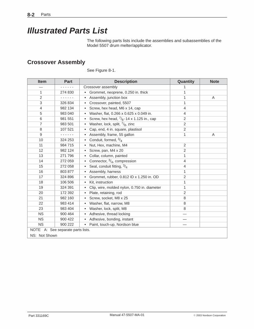
Crossover Assembly See Figure 8-1.
Item Part Description Quantity Note— - - - - - - Crossover assembly 11 274 830 � Grommet, neoprene, 0.250 in. thick 12 - - - - - - � Assembly, junction box 1 A3 326 834 � Crossover, painted, 5507 14 982 134 � Screw, hex head, M6 x 14, cap 45 983 040 � Washer, flat, 0.266 x 0.625 x 0.049 in. 46 981 551 � Screw, hex head, 7/8 -14 x 1.125 in., cap 27 983 501 � Washer, lock, split, 7/8, zinc 28 107 521 � Cap, end, 4 in. square, plastisol 29 - - - - - - � Assembly, frame, 55 gallon 1 A10 324 253 � Conduit, formed, 3/411 984 715 � Nut, Hex, machine, M4 212 982 124 � Screw, pan, M4 x 20 213 271 796 � Collar, column, painted 114 272 059 � Connector, 3/4, compression 415 272 058 � Seal, conduit fitting, 3/4 416 803 877 � Assembly, harness 117 324 896 � Grommet, rubber, 0.812 ID x 1.250 in. OD 218 106 506 � Kit, instruction 119 324 391 � Clip, wire, molded nylon, 0.750 in. diameter 120 172 392 � Plate, retaining, rod 221 982 160 � Screw, socket, M8 x 25 822 983 414 � Washer, flat, narrow, M8 823 983 404 � Washer, lock, split, M8 8NS 900 464 � Adhesive, thread locking —NS 900 422 � Adhesive, bonding, instant —NS 900 222 � Paint, touch-up, Nordson blue —
NOTE A: See separate parts lists.
NS: Not Shown

Parts 8-3
Part 331169C� 2003 Nordson Corporation Manual 47-5507-MA-01
4701163A
6, 7
10
8
1 2
9
11, 12
1317
14, 15
3
16
4, 5
18
19
ÇÇÇÇÇÇÇ
ÇÇÇÇÇÇÇÇÇÇÇÇÇÇ
ÉÉÉÉÉ
21, 22, 23
20
Fig. 8-1 Crossover Assembly
Parts8-4
Part 331169C � 2003 Nordson CorporationManual 47-5507-MA-01
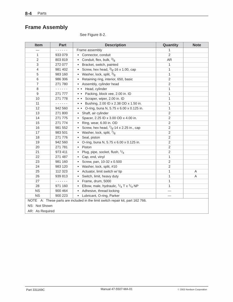
Frame Assembly See Figure 8-2.
Item Part Description Quantity Note— - - - - - - Frame assembly 11 933 079 � Connector, conduit 22 803 819 � Conduit, flex, bulk, 3/8 AR3 272 077 � Bracket, switch, painted 14 981 402 � Screw, hex head, 3/8-16 x 1.00, cap 15 983 160 � Washer, lock, split, 3/8 16 986 306 � Retaining ring, interior, 650, basic 27 271 780 � Assembly, cylinder head 28 - - - - - - � � Head, cylinder 19 271 777 � � Packing, block vee, 2.00 in. ID 110 271 778 � � Scraper, wiper, 2.00 in. ID 111 - - - - - - � � Bushing, 2.00 ID x 2.38 OD x 1.50 in. 112 942 560 � � O-ring, buna N, 5.75 x 6.00 x 0.125 in. 113 271 800 � Shaft, air cylinder 214 271 775 � Spacer, 2.25 ID x 3.00 OD x 4.00 in. 215 271 774 � Ring, wear, 6.00 in. OD 216 981 552 � Screw, hex head, 7/8-14 x 2.25 in., cap 217 983 501 � Washer, lock, split, 7/8 218 271 776 � Seal, piston 219 942 560 � O-ring, buna N, 5.75 x 6.00 x 0.125 in. 220 271 781 � Piston 221 973 411 � Plug, pipe, socket, flush, 1/4 222 271 487 � Cap, end, vinyl 123 981 160 � Screw, pan, 10-32 x 0.500 224 983 120 � Washer, lock, split, #10 225 112 323 � Actuator, limit switch w/ tip 1 A26 939 813 � Switch, limit, heavy duty 1 A27 - - - - - - � Frame, drum, 5000 128 971 160 � Elbow, male, hydraulic, 1/4 T x 1/4 NP 1NS 900 464 � Adhesive, thread locking —NS 900 223 � Lubricant, O-ring, Parker —
NOTE A: These parts are included in the limit switch repair kit, part 162 766.
NS: Not Shown
AR: As Required

Parts 8-5
Part 331169C� 2003 Nordson Corporation Manual 47-5507-MA-01
4701164
27
22, 23, 24,
21
ÉÉÉÉÉÉÉÉÉÉÉÉÉÉÉÉ
ÉÉÉÉÉÉÉÉÉÉÉÉÉÉÉÉ
12
8 9 10
11
ÇÇÇÇ
ÇÇÉÉÉ
ÉÉÉ
ÇÇ
ÉÉ
ÉÉ
6
7
13
14
15
16, 17
20
18, 19
1
2
3, 4, 5
A
A
25, 26
28
9
8
Fig. 8-2 Frame Assembly

Parts8-6
Part 331169C � 2003 Nordson CorporationManual 47-5507-MA-01
Drive Assembly See Figure 8-3.
Item Part Description Quantity Note— - - - - - - Drive assembly 11 939 122 � Seal, conduit fitting, 1/2 12 933 079 � Connector, conduit 23 933 077 � Conduit, flex, bulk, 3/8 AR4 324 725 � Motor, electric, 1 hp, model 5530 15 983 405 � Washer, lock, split, M10 86 984 172 � Nut, hex head, lock, 1/2-13 UNC-2B 17 982 006 � Screw, socket, M8 x 20 28 981 408 � Screw, hex head, 3/8-16 x 1.250 in., cap 49 229 694 � Reducer, speed, worm gear, 10:1 110 982 478 � Screw, hex head, M10 x 30, cap 411 324 019 � Assembly, shaft, drive, 55 gallon 112 983 404 � Washer, lock, split, M8 213 274 307 � Pivot, tube, hose support 114 274 174 � Hanger, hose, 5/8 in. ID and 1-1/8 in. ID 115 274 305 � Arm, support, hanger, welded 1NS 900 236 � Sealant, paste —
AR: As Required
NS: Not Shown

Parts 8-7
Part 331169C� 2003 Nordson Corporation Manual 47-5507-MA-01
4701165
1, 2
9
11
2
8, 5
10, 5
4
3
15
14
13
7, 12
6
A
A
VIEW A
Fig. 8-3 Drive Assembly

Parts8-8
Part 331169C � 2003 Nordson CorporationManual 47-5507-MA-01
Pump Assembly See Figure 8-4.
Item Part Part Part Description Quantity Note— 333 720 — — Pump assembly, 3/4 gerotor, 1200 psi
(5/16 in. ID Hose)—
— — 333 720 — Pump Assembly, 3/4 gerotor, 1200 psi(5/8 in. ID Hose)
—
— — — 333 719 Pump Assembly, 3/4 gerotor, 1000 psi(1 1/8 in. ID Hose)
—
1 274 312 274 312 274 312 � Body, pump 12 942 371 942 371 942 371 � O-ring, Viton, 3.375 x 3.625 x 0.125 in. 13 271 916 271 916 271 916 � Plate, pump, upper 14 271 889 271 889 271 889 � Retainer, gerotor, 0.750 in. thick 15 271 917 271 917 271 917 � Plate, pump, lower 16 981 557 981 557 981 557 � Screw, socket head, 1/4-20 x 1.750 in. 67 981 233 981 233 981 233 � Screw, socket head, 1/4-20 x 1.000 in. 28 271 888 271 888 271 888 � Gerotor set, 6-tooth, 0.750 in. thick 19 172 326 172 326 172 326 � Shaft, pump, 750 gerotor 110 272 045 272 045 272 044 � Valve, relief, pressure 111 945 025 945 025 945 025 � � O-ring, Viton, 0.755 x 0.970 in. 112 940 141 940 141 940 141 � � O-ring, Viton, 0.500 x 0.625 x 0.063 in. 113 236 366 236 366 236 366 � Seal, shaft, 0.625 x 0.875 in. 214 274 300 274 300 274 300 � Bearing, needle, open, 0.625 in. 215 168 054 168 054 168 054 � Key, woodruff, #3, hardened 116 236 365 236 365 236 365 � Seal, shaft, 0.625 x 0.812 in. 117 167 002 167 002 � Manifold, pump, single hose, (5/16 and
5/8 in. ID)1
17 272 042 272 042 � Manifold, pump, dual hose, (5/16 and5/8 in. ID)
1
17 272 043 � Manifold, pump, single hose, (1 1/8 in. ID) 117 115 878 � Manifold, pump, dual hose, (1 1/8 in. ID) 118 236 348 236 348 236 348 � Bearing, needle, closed, 0.625 in. 119 986 310 986 310 986 310 � Retaining ring, internal, 84, spiral 120 940 201 940 201 940 201 � O-ring, Viton, 0.864 x 0.070 in. 121 981 101 981 101 981 101 � Screw, socket set, 10-32 x 0.187, cup 122 178 170 178 170 178 170 � Key, 1/8 x 1/8 x 0.800 in. 123 973 431 973 431 973 431 � Plug, pipe, 1/2 npt 1 A24 271 884 271 884 271 884 � Valve, manual, 1/4 npt 125 972 619 � Connector, male, 37 in., 9/16-18 x 1/2 npt
(5/16 in. ID)1 A
25 972 620 � Connector, male, 37 in., 1 1/16-12 x 1/2 npt(5/8 in. ID)
1 A
25 972 621 � Connector, male, 37 in., 1 5/8-12 x 1 1/4 npt(1 1/8 in. ID)
1
25 803 536 � Connector, male, 37 in., 1 5/8-12 x 1 npt(1 1/8 in. ID
2
Continued...

Parts 8-9
Part 331169C� 2003 Nordson Corporation Manual 47-5507-MA-01
Item Part Part Part Description Quantity Note26 981 556 981 556 981 556 � Screw, socket head, 1/4-20 x 1.50 in. 327 172 328 172 328 172 328 � Block, coupling, shaft, 1.250 in. long 128 272 046 272 046 272 046 � Washer, bearing, 0.620 x 0.960 x 0.062 in. 129 973 402 973 402 973 402 � Plug, pipe, 1/8 nptf (single hose units only) 1NS 900 236 900 236 900 236 � Sealant, paste —NS 900 318 900 318 900 318 � Grease, flourinated, 2 oz. —NS 902 504 902 504 902 504 � Tape —
NOTE A: Two of these parts are enclosed with the dual hose manifold and pump assembly.
AR: As Required
NS: Not Shown
4701167
22
21
27
2625
24 28
17
23 29
13
1420
10
11
12
1
2
14
13
3
4
8
7
915
19
16
5
18
6
Fig. 8-4 Pump Assembly

Parts8-10
Part 331169C � 2003 Nordson CorporationManual 47-5507-MA-01
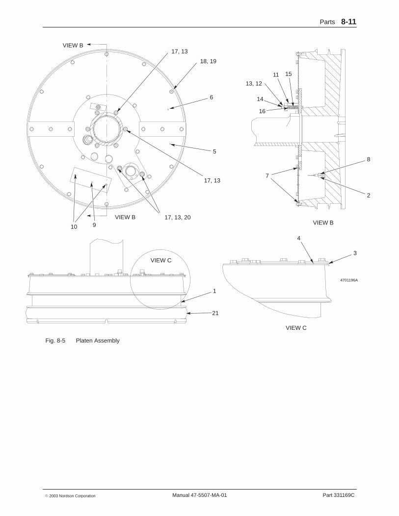
Platen Assembly See Figure 8-5.
Item Part Description Quantity Note— - - - - - - Platen assembly 11 326 813 � Platen 12 - - - - - - � RTD, nickel, tip, 0.250 x 5.00 in. 1 A3 326 809 � Plate, cover, seam 24 326 810 � Gasket, cover, seam 25 326 791 � Cover, platen, front 16 326 792 � Cover, platen, rear 17 185 377 � Tube, Viton, seal, platen cvr 9 ft8 272 279 � Connector, temp sensor, 1/4 19 - - - - - - � Tag, warning, disconnect power 110 981 905 � Screw, drive, round, 2 x 0.187 in. 211 272 069 � Clamp, Manifold 112 984 707 � Nut, hex, regular, M8 113 983 404 � Washer, lock, split, M8 114 185 376 � Stud, M8 x 75 115 272 068 � Spring, Comp, 2.000 x 0.328 ID x 0.042 in. 116 125 112 � Nut, hex, jam, M8 117 981 528 � Screw, socket, M8 x 30 818 982 134 � Screw, hex, cap, M6 x 14 2319 983 410 � Washer, flat, narrow, M6 2320 983 013 � Washer, flat, regular, M8 221 - - - - - - � Seal, platen 1 ANS 275 386 � Compound, thermal joint —NS 982 261 � Screw, pan, rec, M3.5 x 10 1 BNS 226 831 � Washer, flat, M3.5 1 BNS 983 424 � Washer, split lock, M3.5 1 BNS 900 413 � Sealant, RTV, red —
�
�
NOTE A: Specific part numbers are given in the table of recommended spare parts.
B: Used to secure ground wire.
NS: Not Shown
Parts 8-11
Part 331169C� 2003 Nordson Corporation Manual 47-5507-MA-01
4701196A
18, 19
6
5
17, 13
10
17, 13, 20
1
4
3
7
14
13, 12
16
8
2
11 15
9
21
VIEW B
VIEW C
VIEW C
VIEW BVIEW B
17, 13
Fig. 8-5 Platen Assembly

Parts8-12
Part 331169C � 2003 Nordson CorporationManual 47-5507-MA-01
Junction Box Assembly See Figure 8-6.
Item Part Description Quantity Note— - - - - - - Junction box 11 324 344 � Assembly, cover, junction box w/ tag 12 981 428 � � Screw, captive, 10-32 x 0.432 in. 23 983 122 � � Washer, retainer, #10 2
NS 242 654 � � Gasket, cabinet 4 ft4 324 357 � � Cover, junction box, painted 15 981 020 � Screw, pan, 6-32 x 0.250 in. 26 983 100 � Washer, lock, interior, #6 27 324 608 � Block, terminal, modular, 12-station 18 939 355 � Socket, relay, 8-pin 19 984 101 � Nut, hex, machine, 6-32 410 933 281 � Block, terminal, 4-station 111 324 358 � Junction box, crossover, painted 112 983 120 � Washer, lock, split, #10 213 984 129 � Nut, hex, machine, 10-32, brass 314 271 221 � Lug, 45, double, 0.250 in., 0.438 in. 315 240 674 � Tag. Ground 1
NS: Not Shown
4701170
11
7
2
4
8
3
10
5, 6
9
1
14
1213
15
Fig. 8-6 Junction Box Assembly

Parts 8-13
Part 331169C� 2003 Nordson Corporation Manual 47-5507-MA-01
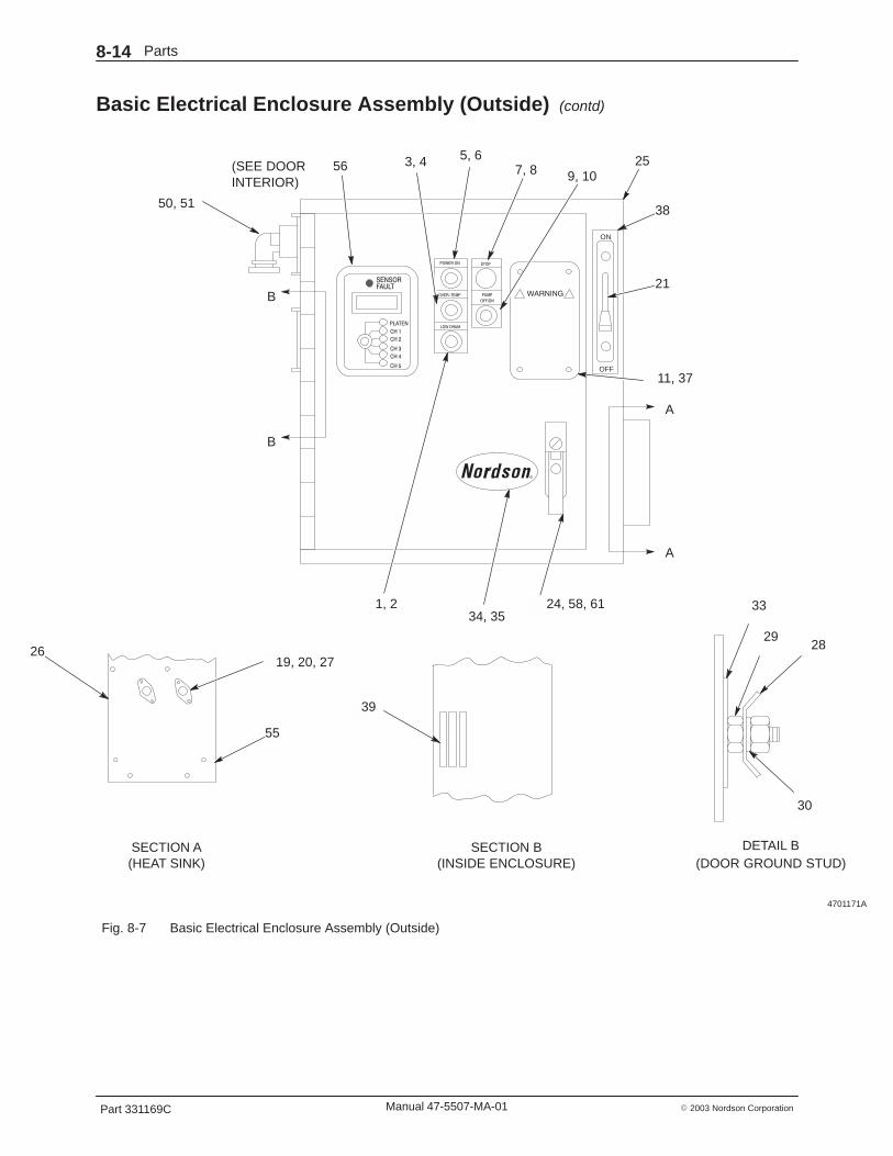
Basic Electrical Enclosure Assembly (Outside) See Figures 8-7.
Item Part Description Quantity Note— - - - - - - Basic electrical enclosure assembly 11 939 359 � Light, pilot, 120 volt, amber 12 324 309 � Plate, legend, low drum 13 939 331 � Light, pilot, 120 volt, red 14 324 308 � Plate, legend, over-temperature 15 939 811 � Button, push, illuminated, guarded 16 324 306 � Plate, legend, power on 17 939 353 � Switch, push button, stop 18 - - - - - - � Plate, legend, e-stop 19 939 812 � Switch, selector, illuminated, 2-position 110 324 311 � Plate, legend, pump on/off 111 - - - - - - � Tag, warning, disconnect power 119 981 022 � Screw, filister, 6-32 x 0.375 in. 820 983 100 � Washer, lock, interior, #6 821 324 327 � Mechanism, handle, disconnect 124 324 328 � Handle assembly, door 125 324 355 � Cabinet, electrical, painted 126 119 030 � Heatsink, machined, electrical box 127 939 644 � Triac, tank, control, 25 am 228 271 221 � Lug, 45, double, 0.250 in., 0.438 in. 429 984 129 � Nut, hex, machine, 10-32, brass 530 983 120 � Washer, lock, split, #10 533 240 674 � Tag, ground 234 136 418 � Name plate, Nordson oval 135 984 529 � Nut, spring, push on. 0.125 in. 337 985 111 � Rivet, blind, 3/32 x 0.125, aluminum 438 - - - - - - � Plate, on/off main breaker 139 335 176 � Clamp, cable, ribbon, 3 in. maximum 150 939 637 � Connector, conduit 151 274 385 � Seal, conduit fitting, 1 1/4 in. 155 981 544 � Screw, socket head, 6-32 x 0.500 1056 - - - - - - � Wire group, basic LCU 158 156 408 � Lock bar, lower 161 156 407 � Lock bar, upper 1NS 275 386 � Compound, thermal joint, 2 oz. —
NS: Not Shown
Parts8-14
Part 331169C � 2003 Nordson CorporationManual 47-5507-MA-01
Basic Electrical Enclosure Assembly (Outside) (contd)
4701171A
POWER ON
OVER−TEMP
LOW DRUM
STOP
PUMP
OFF/ON
ON
OFF
25
38
21
11, 37
24, 58, 6134, 35
5, 63, 456
50, 51
1, 2
7, 8 9, 10(SEE DOORINTERIOR)
DETAIL B(DOOR GROUND STUD)
33
2928
30
39
SECTION B(INSIDE ENCLOSURE)
19, 20, 2726
55
SECTION A(HEAT SINK)
A
A
B
B
CH 1
CH 2
CH 3
CH 4
CH 5
SENSORFAULT
PLATEN
Fig. 8-7 Basic Electrical Enclosure Assembly (Outside)

Parts 8-15
Part 331169C� 2003 Nordson Corporation Manual 47-5507-MA-01
Basic Electrical Enclosure Assembly (Inside) See Figures 8-8.
Item Part Description Quantity Note— - - - - - - Basic electrical enclosure assembly 112 271 964 � Duct, wire, 14-in. 113 981 064 � Screw, pan, 8-32 x 0.375 714 324 335 � Contactor, main power 115 983 011 � Washer, lock, interior, #8 716 939 020 � Fuse, 30.00, fast-acting, 600 volt 217 939 509 � Fuse, 5.00, time-delay, 250 volt 118 939 762 � Fuse block, 8-pole 119 981 022 � Screw, filister, 6-32 x 0.375 in. 820 983 100 � Washer, lock, interior, #6 822 324 354 � Panel, inner, electrical enclosure, painted 123 324 336 � Block, terminal, electrical box 128 271 221 � Lug, 45, double, 0.250 in., 0.438 in. 429 984 129 � Nut, hex, machine, 10-32, brass 530 983 120 � Washer, lock, split, #10 531 981 156 � Screw, pan, 10-32 x 1.000 in., brass 132 939 488 � Terminal, wire, ground 133 240 674 � Tag, ground 235 984 529 � Nut, spring, push on. 0.125 in. 336 272 620 � Suppressor, arc, w/ terminals 140 933 397 � Gasket, base, connector 241 933 392 � Base, connector, panel mount 142 933 395 � Insert, connector, receptacle 143 981 029 � Screw, filister, 6-32 x 0.500 in. 844 984 101 � Nut, hex, machine, 6-32 845 983 102 � Washer, lock, split, #6 846 324 252 � Plate, cover, connector cut-out 147 324 442 � Standoff, 10-32 m/f x 3.00 in. long 148 981 160 � Screw, pan, 10-32 x 0.500 249 939 528 � Socket, crimp contact 1652 933 396 � Receptacle cover 153 242 837 � Mount, cable strap 254 939 295 � Fuse, 8.00, time-delay, 250 volt 257 939 827 � Block, fuse 159 984 152 � Nut, hex, 3/8-16 460 983 160 � Washer, lock, 3/8 461 816 243 � Fuse, 1.50, time delay, 500 volt 1 A
NOTE A: Fuse is required for 380 volt and 415 volt units only.

Parts8-16
Part 331169C � 2003 Nordson CorporationManual 47-5507-MA-01
Basic Electrical Enclosure Assembly (Inside) (contd)
4701172A
OFFOPEN COVER
ON
53
12, 13,
22
]
13, 15,
40, 46
35, 40,
30, 47,
13, 14,
15
23
41, 42
48
15, 36
49, 52
LCU (RIBBONCABLE AND
CONNECTORS NOT SHOWN)
SEE DETAIL B
31 2230
29
29
30
28
33 32
SEE DETAIL A
DETAIL A(INNER PANEL GROUND STUD)
19, 20, 54, 57
DOOR INTERIOR(LATCH NOT SHOWN)
43, 44, 45
59, 60
F8 F4 F5 F6 F10 F11
F13 F14
KM2
KM1 F8
18, 19, 20
16 17 5416
61
SEE DETAIL B
F5 F6 F10 F11F4
DETAIL B
Fig. 8-8 Basic Electrical Enclosure Assembly (Inside)
Parts 8-17
Part 331169C� 2003 Nordson Corporation Manual 47-5507-MA-01
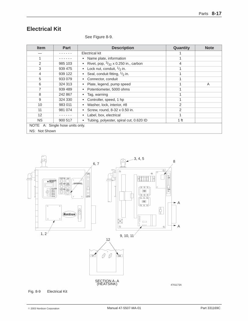
Electrical Kit See Figure 8-9.
Item Part Description Quantity Note— - - - - - - Electrical kit 11 - - - - - - � Name plate, information 12 985 103 � Rivet, pop, 3/32 x 0.250 in., carbon 43 939 475 � Lock nut, conduit, 1/2 in. 14 939 122 � Seal, conduit fitting, 1/2 in. 15 933 079 � Connector, conduit 16 324 313 � Plate, legend, pump speed 1 A7 939 489 � Potentiometer, 5000 ohms 18 242 867 � Tag, warning 19 324 330 � Controller, speed, 1 hp 110 983 011 � Washer, lock, interior, #8 211 981 074 � Screw, round, 8-32 x 0.50 in. 212 - - - - - - � Label, box, electrical 1NS 900 517 � Tubing, polyester, spiral cut, 0.620 ID 1 ft
NOTE A: Single hose units only.
NS: Not Shown
4701173A
CH 1CH 2CH 3CH 4CH 5
SENSORFAULT
POWER ON
OVER−TEMP
LOW DRUM
STOP
PUMPOFF/ON
SPEED
WARNING
ON
OFF
OFF
ON
3, 4, 58
9, 10, 11
6, 7
1, 2
12
SECTION A-A(HEATSINK)
A
A
PLATEN
Fig. 8-9 Electrical Kit

Parts8-18
Part 331169C � 2003 Nordson CorporationManual 47-5507-MA-01
Voltage Kit See Figure 8-10.
Item Part Description Quantity Note— - - - - - - Voltage kit 1 A1 939 122 � Seal, conduit fitting, 1/2 in. 22 939 475 � Lock nut, conduit, 1/2 in. 23 804 137 � Connector, 90� elbow, 1/2 in. conduit 14 248 375 � Conduit, flex, bulk, 1/2 in. 1 ft5 324 343 � Connector, conduit, straight, 0.500 in. 16 324 326 � Switch, fusible, 100 amp (200/240 volt units) 1
324 325 � Switch, fusible, 60 amp (380/415/480 volt units) 17 939 056 � Fuse, 100 amp, 250 volt (200/240 volt units) 3
939 420 � Fuse, 60 amp, 600 volt (380/415 volt units) 3939 470 � Fuse, 50 amp, 600 volt (480 volt units) 3
8 981 064 � Screw, pan head, 8-32 x 0.375 in. 69 939 763 � Relay, solid state, 660 VAC, 90 amp (200 volt units) 3
939 764 � Relay, solid state, 530 VAC, 40 amp (all other units) 310 983 011 � Washer, lock, interior, #8 611 939 823 � Transformer, 5 KVA (200/380/415 volt units) 1
939 816 � Transformer, 5 KVA (240/480 volt units) 112 983 150 � Washer, lock, split, 5/16 413 984 140 � Nut, hex, regular, 5/16-18 414 937 297 � Contactor, 63 amp, 120 VAC (200/240 volt units) 1
937 289 � Contactor, 63 amp, 120 VAC (380/415/480) 115 933 156 � Lug, 90�, double, 0.250 in., 0.438 in. 616 111 962 � Standoff, 10-32 x 0.500 in. 117 981 160 � Screw, pan, 10-32 x 0.500 in. 118 983 120 � Washer, lock, split, #10 119 816 232 � Transformer assembly, control (380/415 volt units) 1NS 900 298 � Compound, heat sink, 5 oz. tube —
NOTE A: 200, 240, 380/415, or 480 volt kits available.
NS: Not Shown

Parts 8-19
Part 331169C� 2003 Nordson Corporation Manual 47-5507-MA-01
4701174A
6
7
8, 10, 14
1, 2, 5
4
1, 2, 3
12, 13
11
16, 17, 18
8, 9,10, 15
SECTION A-A(HEATSINK)
A
A
19
Fig. 8-10 Voltage Kit

Parts8-20
Part 331169C � 2003 Nordson CorporationManual 47-5507-MA-01
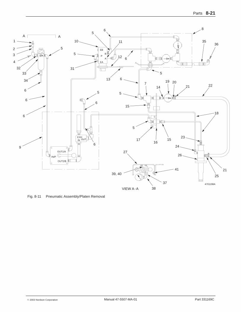
Pneumatic Assembly, Platen Removal See Figures 8-11.
Item Part Description Quantity Note— - - - - - - Pneumatic assembly 11 973 996 � Disconnect, quick, 3/8, male 12 973 520 � Coupling, pipe, hyd, 3/8 in. 13 973 067 � Nipple, extra-heavy, 3/8 x 2.00 in. 14 973 175 � Ell, pipe, hyd, 90 deg, 3/8 in. 15 972 183 � Elbow, male, 3/8 tube x 1/4 NPT 96 900 564 � Tubing, nylon, black, 0.375 OD 30 ft7 973 275 � Tee, pipe, 1/4 brass 18 - - - - - - � Regulator, pre-set, assy, bov2 1 A9 - - - - - - � Valve, manual elevator, bov2 1 A10 973 411 � Plug, pipe, socket, flush, 1/4 in. 111 152 189 � Valve, 90 deg, sel, 4-way, 5-port 112 121 447 � Panel, pneumatic, gp 113 981 283 � Screw, pan, 8-32 x 0.375 in. 814 973 085 � Nipple, steel, sched 40, 1/4, 0.870 in. 215 971 265 � Connector, male, 1/4 tube x 1/4 NPT 216 119 721 � Bracket, crossover, 5000, pa 117 982 134 � Screw, hex, M6 x 14, cap 218 815 965 � Tubing, 1/4 OD x 0.100 8.7 ft19 305 908 � Regulator, pre-set, 7 psi 120 326 824 � Nipple, hose, 1/2 x 1/4 NPT 121 160 927 � Clamp, tubing, worm drive, 0.560-1.060 in. 222 326 823 � Hose, silicone, 0.500 ID x 0.130 wide 4.7 ft23 100 395 � Connector, male, 1/4 tube 124 100 423 � Elbow, male, 1/4 tube x 1/8 NPT 125 326 825 � Nipple, hose, 1/4 x 3/8 NPT 126 326 812 � Valve, assy, bov2 127 119 646 � Enclosure, pneumatic, painted 131 272 556 � Muffler, low-profile, 1/4 NP 132 973 979 � Adapter, SAE, 3/8 x 1/4, brass 133 324 207 � Filter, reg, 1/4 NPTF, 5-150 psig 134 971 175 � Connector, male, 3/8 tube x 1/8 NPT 135 843 048 � Hose, 0.313 ID TFE, 4 ft 136 972 200 � Ell, male, 37, 9/16-18 x 1/4 137 973 037 � Nipple, hex, 1/4 x 1/4 x 1.450 in. 138 973 152 � Elbow, pipe, 90 deg, 1/4, galv 139 983 504 � Washer, flat, 0.281 x 0.734 x 0.630 in. 240 984 210 � Nut, hex, jam, 1/4−20 441 983 409 � Washer, lock, split, M6 2NS 900 419 � Adhesive, retaining, cylindrical —NS 900 236 � Sealant, paste —
NOTE A: See separate parts list.
NS: Not Shown
Parts 8-21
Part 331169C� 2003 Nordson Corporation Manual 47-5507-MA-01
4701198A
A A1
32 31
65
10
5
52
3
4
33
34
6
6
6
5
6
6
11
12
13
6
3635
8
22212019
14
6
5
7
5
15
5
1716
15
18
23
24
26
25
21
27
39, 4041
37
38
9
VIEW A-A
OUT1/A
IN/P
OUT2/B
EB
P
EA
B
A
EXHIN OUT
Fig. 8-11 Pneumatic Assembly/Platen Removal

Parts8-22
Part 331169C � 2003 Nordson CorporationManual 47-5507-MA-01
Pneumatic Assembly, Platen Removal (contd)
See Figure 8-12.
Item Part Description Quantity Note— - - - - - - Pneumatic assembly contd. 18 - - - - - - � Regulator, pre-set, assy, bov2 1 A9 - - - - - - � Valve, manual elevator, bov2 1 A11 152 189 � Valve, 90 deg, sel, 4-way, 5-port 112 121 447 � Panel, pneumatic, gp 113 981 283 � Screw, pan, 8-32 x 0.375 in., stl, bl 816 119 721 � Bracket, crossover, 5000, pa 118 815 965 � Tubing, 1/4 OD x 0.100 8.7 ft22 326 823 � Hose, silicone, 0.500 ID x 0.130 wide 4.7 ft27 119 646 � Enclosure, pneumatic, painted 128 329 015 � Screw, oval, 5-40 x 0.750 in. 229 326 828 � Clip, 2 tube, 3/8 230 939 004 � Strap, cable, 0.060-1.750 in., natural 1939 983 504 � Washer, flat, 0.281 x 0.734 x 0.630 in. 2
NOTE A: See separate parts list.
4701178A
DSECTION C-C
SECTION D-D
SECTION E-E
16 2730
8
1828, 29
9
11
12
9
11
13
39
27
18, 22
E
E
D
C
C
Fig. 8-12 Pneumatic Assembly/Platen Removal
Parts 8-23
Part 331169C� 2003 Nordson Corporation Manual 47-5507-MA-01
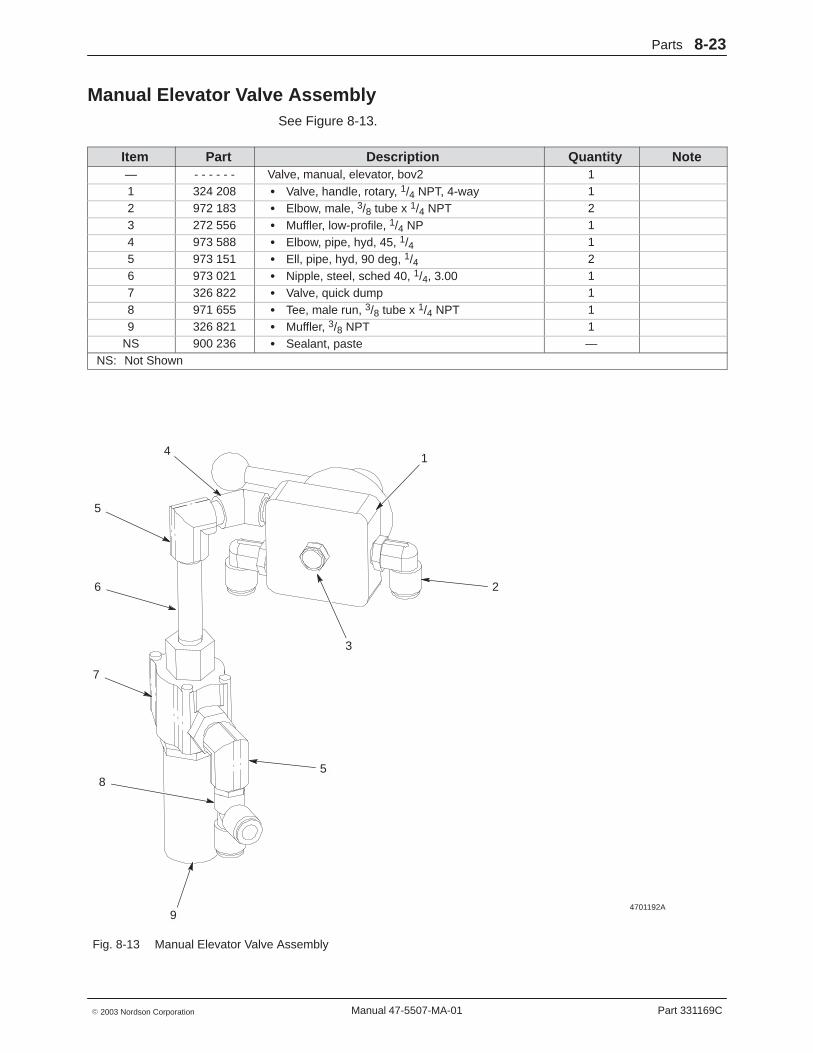
Manual Elevator Valve Assembly See Figure 8-13.
Item Part Description Quantity Note— - - - - - - Valve, manual, elevator, bov2 11 324 208 � Valve, handle, rotary, 1/4 NPT, 4-way 12 972 183 � Elbow, male, 3/8 tube x 1/4 NPT 23 272 556 � Muffler, low-profile, 1/4 NP 14 973 588 � Elbow, pipe, hyd, 45, 1/4 15 973 151 � Ell, pipe, hyd, 90 deg, 1/4 26 973 021 � Nipple, steel, sched 40, 1/4, 3.00 17 326 822 � Valve, quick dump 18 971 655 � Tee, male run, 3/8 tube x 1/4 NPT 19 326 821 � Muffler, 3/8 NPT 1
NS 900 236 � Sealant, paste —NS: Not Shown
4701192A
14
5
6
7
8
9
3
2
5
Fig. 8-13 Manual Elevator Valve Assembly

Parts8-24
Part 331169C � 2003 Nordson CorporationManual 47-5507-MA-01
Regulator Assembly See Figure 8-14.
Item Part Description Quantity Note— - - - - - - Regulator, pre-set, assy, bov2 11 973 275 � Tee, pipe, 1/4, brass 22 973 978 � Adapter, bulkhead, 1/4 NPT 13 330 483 � Valve, check, 1/4, male 14 326 817 � Regulator, pre-set, 10 psi 15 973 021 � Nipple, steel, sched 40, 1/4, 3.00 16 972 183 � Elbow, male, 3/8 tube x 1/4 NPT 27 326 818 � Regulator, pre-set, 30 psi 18 972 200 � Ell, male 37, 9/16-18 x 1/4 1
NS 900 236 � Sealant, paste —NS: Not Shown
4701193A
12
3
5
4
6
7
8
1
Fig. 8-14 Regulator Assembly

Parts 8-25
Part 331169C� 2003 Nordson Corporation Manual 47-5507-MA-01
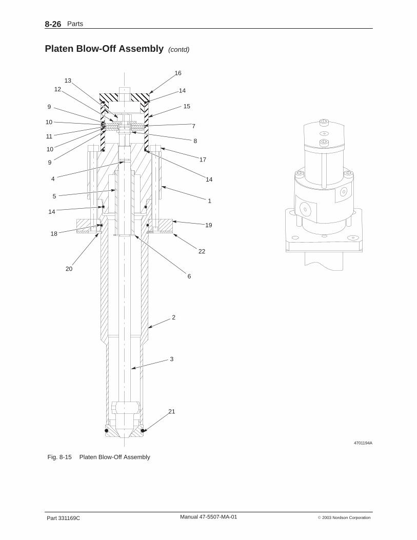
Platen Blow-Off Assembly See Figure 8-15.
Item Part Description Quantity Note— - - - - - - Blow-off valve assembly 11 326 796 � Body, gland, needle, bov2 12 326 807 � Tube, base, assy, bov2 13 326 805 � Needle, bov2 14 940 101 � O-ring, Viton, 0.239 ID x 0.070 wide, brass 15 326 800 � Spring, 600 OD x 0.072 x 3.00 16 986 328 � Retaining ring, ext, 37, e-ring 17 940 090 � O-ring, Viton, 0.208 ID x 0.070 wide, brass 18 240 275 � Retainer, piston 19 240 300 � Disc, piston 210 240 299 � Seal, piston 211 326 802 � Spacer, piston, cup, bov2 112 983 034 � Washer, flat, oversized, M6 113 984 092 � Nut, hex, lock, torque, M6 114 940 261 � O-ring, Viton, 1.250 x 1.375 x 0.063 in. 315 326 797 � Cylinder, bov2 116 326 798 � Head, cylinder, bov2 117 982 171 � Screw, socket, M5 x 60, bl 418 940 281 � O-ring, Viton, 1.375 x 1.500 x 0.063 in. 119 326 806 � Plate, mounting, bov2 120 986 351 � Retaining ring, ext, 150, invert 121 941 201 � O-ring, Viton, 1.000 x 1.188 x 0.094 in. 122 326 808 � Gasket, mounting, bov2 1NS 900 493 � Lubricant, Parker hi-temperature —
NS: Not Shown
Parts8-26
Part 331169C � 2003 Nordson CorporationManual 47-5507-MA-01
Platen Blow-Off Assembly (contd)
4701194A
ÇÇÇÇÇÇÇÇÇÇÇÇÇÇÇÇÇÇÉÉÉÉÉÉ
ÉÉÉÉÉÉÉÉÉÉÉÉ
16
9
11
1
14
1918
22
21
3
2
14
20
4
10
1213
15
7
8
17
14
6
10
9
5
Fig. 8-15 Platen Blow-Off Assembly
Parts 8-27
Part 331169C� 2003 Nordson Corporation Manual 47-5507-MA-01
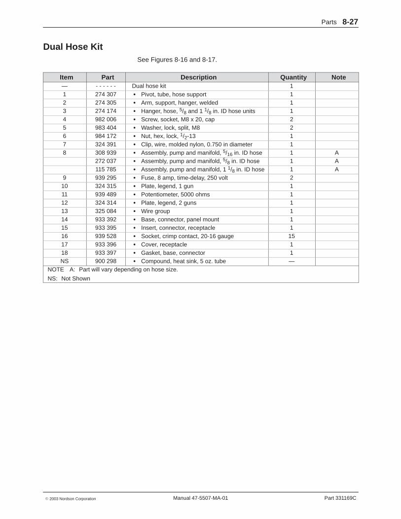
Dual Hose Kit See Figures 8-16 and 8-17.
Item Part Description Quantity Note— - - - - - - Dual hose kit 11 274 307 � Pivot, tube, hose support 12 274 305 � Arm, support, hanger, welded 13 274 174 � Hanger, hose, 5/8 and 1 1/8 in. ID hose units 14 982 006 � Screw, socket, M8 x 20, cap 25 983 404 � Washer, lock, split, M8 26 984 172 � Nut, hex, lock, 1/2-13 17 324 391 � Clip, wire, molded nylon, 0.750 in diameter 18 308 939 � Assembly, pump and manifold, 5/16 in. ID hose 1 A
272 037 � Assembly, pump and manifold, 5/8 in. ID hose 1 A115 785 � Assembly, pump and manifold, 1 1/8 in. ID hose 1 A
9 939 295 � Fuse, 8 amp, time-delay, 250 volt 210 324 315 � Plate, legend, 1 gun 111 939 489 � Potentiometer, 5000 ohms 112 324 314 � Plate, legend, 2 guns 113 325 084 � Wire group 114 933 392 � Base, connector, panel mount 115 933 395 � Insert, connector, receptacle 116 939 528 � Socket, crimp contact, 20-16 gauge 1517 933 396 � Cover, receptacle 118 933 397 � Gasket, base, connector 1NS 900 298 � Compound, heat sink, 5 oz. tube —
NOTE A: Part will vary depending on hose size.
NS: Not Shown

Parts8-28
Part 331169C � 2003 Nordson CorporationManual 47-5507-MA-01
Dual Hose Kit (contd)
4701183A
8
1 2
3
4, 56
BB
VIEW A-A
VIEW B-B7
C
C
A
A
(BEHIND COLUMN)
Fig. 8-16 Dual Hose Kit
4701184A
17
14, 15, 1617, 18
9
10
11, 12
9, 13
SEE DETAIL B
SEE DETAIL A
F
F
VIEW D-D
VIEW C-C
D
D
Fig. 8-17 Dual Hose Kit

Parts 8-29
Part 331169C� 2003 Nordson Corporation Manual 47-5507-MA-01
See Figure 8-18.
Item Part Description Quantity Note— - - - - - - Dual hose kit contd. 111 939 489 � Potentiometer, 5000 ohms 117 933 396 � Cover, receptacle 119 104 049 � Barrier, terminal block 220 104 050 � Jumper, terminal block 321 981 039 � Screw, pan head, 6-32 x 0.312 in. 1022 983 100 � Washer, lock, interior, #6 1023 145 714 � Relay, solid-state, 4 amp, 240 volt 324 939 644 � Triac, tank, control, 25 amp 225 324 912 � Module, temperature, 100� -450� F 226 324 226 � Label, dual hose kit 127 324 403 � Assembly, circuit board, 2-gun controller 128 324 337 � Bracket, support, module 129 981 427 � Screw, pan head, 6-32 x 0.250 230 112 295 � Cover, module, LCU 1
4701185A
20
19
20
19
20
5678
15161718
18
11
29
26
27
21, 22, 24
25
26
2817
21, 22, 23
17
29, 30
DETAIL A DETAIL B
SECTION E-E
SECTION F-F(HEATSINK)
(INSIDE DOOR;LATCH NOT SHOWN)
Fig. 8-18 Dual Hose Kit
Parts8-30
Part 331169C � 2003 Nordson CorporationManual 47-5507-MA-01
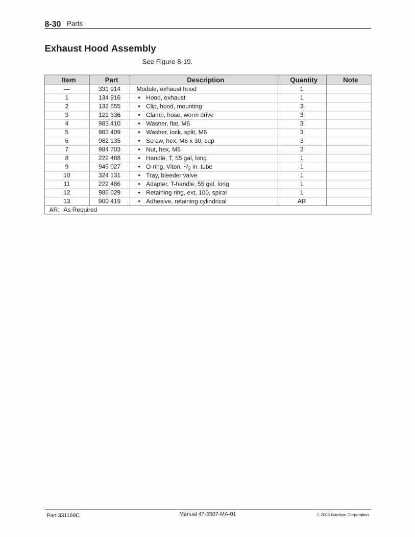
Exhaust Hood Assembly See Figure 8-19.
Item Part Description Quantity Note— 331 914 Module, exhaust hood 11 134 916 � Hood, exhaust 12 132 655 � Clip, hood, mounting 33 121 336 � Clamp, hose, worm drive 34 983 410 � Washer, flat, M6 35 983 409 � Washer, lock, split, M6 36 982 135 � Screw, hex, M6 x 30, cap 37 984 703 � Nut, hex, M6 38 222 488 � Handle, T, 55 gal, long 19 945 027 � O-ring, Viton, 1/2 in. tube 110 324 131 � Tray, bleeder valve 111 222 486 � Adapter, T-handle, 55 gal, long 112 986 029 � Retaining ring, ext, 100, spiral 113 900 419 � Adhesive, retaining cylindrical AR
AR: As Required

Parts 8-31
Part 331169C� 2003 Nordson Corporation Manual 47-5507-MA-01
4701195AB
ÉÉÉÉÉÉÉÉÉÉÉÉ
ÉÉÉÉÉÉÉÉÉÉÉÉÉÉÉÉÉÉÉÉÉÉÉÉÉÉÉÉÉÉ
ÇÇÇÇÇÇÇÇÇÇÇÇÇÇÇÇÇÇÇÇÇÇÇÇÇÇÇÇÇÇÇÇÇÇÇÇÇÇÇÇÇÇÇÇÇÇÇÇÇÇÇÇÇÇÇÇÇÇÇÇÇÇÇÇÇÇÇÇÇÇÇÇ
ÉÉÇÇ
ÉÉÉÉÇÇÇÇÇÇÇ
3
2
4, 5, 6, 7 1
8, 9 10, 11, 12, 13
2
2
2
Fig. 8-19 Exhaust Hood Assembly

Parts8-32
Part 331169C � 2003 Nordson CorporationManual 47-5507-MA-01
Hose Parts Lists The following parts lists include hoses for the Model 5507 drummelter/applicator.
Hoses for Manual Guns See Figure 8-20.
Item Part Description Quantity Note— 276 950 Manual Hose, 10 ft, 5/16 in. ID 1— 276 951 Manual Hose, 16 ft, 5/16 in. ID 1— 276 952 Manual Hose, 24 ft, 5/16 in. ID 1— 276 953 Manual Hose, 30 ft, 5/16 in. ID 1— 276 938 Manual Hose, 10 ft, 5/8 in. ID 1— 276 939 Manual Hose, 16 ft, 5/8 in. ID 1— 276 940 Manual Hose, 24 ft, 5/8 in. ID 1— 276 941 Manual Hose, 30 ft, 5/8 in. ID 1— 120 958 Manual Hose, 10 ft, 5/16 in. ID 1 A— 120 959 Manual Hose, 16 ft, 5/16 in. ID 1 A— 127 317 Manual Hose, 10 ft, 5/8 in. ID 1 B— 127 318 Manual Hose, 16 ft, 5/8 in. ID 1 B— 127 319 Manual Hose, 14 ft, 5/8 in. ID 1 B
NOTE A: Equipped with corrugated cover for additional protection from abrasion.
B: For use with Series A-2 handguns only.
4710211
Fig. 8-20 Manual Gun Hose

Parts 8-33
Part 331169C� 2003 Nordson Corporation Manual 47-5507-MA-01
Hoses for Automatic Guns See Figure 8-21.
Item Part Description Quantity Note— 276 946 Automatic Hose, 10 ft, 5/16 in. ID 1— 276 947 Automatic Hose, 16 ft, 5/16 in. ID 1— 276 948 Automatic Hose, 24 ft, 5/16 in. ID 1— 276 949 Automatic Hose, 30 ft, 5/16 in. ID 1— 276 934 Automatic Hose, 10 ft, 5/8 in. ID 1— 276 935 Automatic Hose, 16 ft, 5/8 in. ID 1— 276 936 Automatic Hose, 24 ft, 5/8 in. ID 1— 276 937 Automatic Hose, 30 ft, 5/8 in. ID 1— 100 706 Automatic Hose, 10 ft, 1-1/8 in. ID 1— 100 707 Automatic Hose, 16 ft, 1-1/8 in. ID 1
4710212
Fig. 8-21 Automatic Gun Hose

Parts8-34
Part 331169C � 2003 Nordson CorporationManual 47-5507-MA-01
Transfer Hoses See Figure 8-22.
Item Part Description Quantity Note— 276 942 Transfer Hose, 10 ft, 5/8 in. ID 1 A— 276 943 Transfer Hose, 16 ft, 5/8 in. ID 1 A— 276 944 Transfer Hose, 24 ft, 5/8 in. ID 1 A— 276 945 Transfer Hose, 30 ft, 5/8 in. ID 1 A— 100 704 Transfer Hose, 10 ft, 1-1/8 in. ID 1 A— 100 705 Transfer Hose, 16 ft, 1-1/8 in. ID 1 A
NOTE A: Transfer hoses are used only when there is no gun at the end of the hose
4710216
Fig. 8-22 Transfer Hose
Parts 8-35
Part 331169C� 2003 Nordson Corporation Manual 47-5507-MA-01
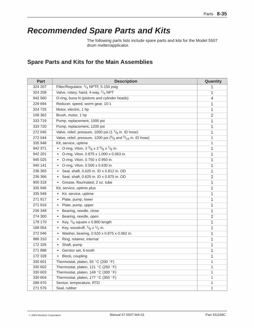
Recommended Spare Parts and Kits The following parts lists include spare parts and kits for the Model 5507drum melter/applicator.
Spare Parts and Kits for the Main Assemblies
Part Description Quantity324 207 Filter/Regulator, 1/4 NPTF, 5-150 psig 1324 208 Valve, rotary, hand, 4-way, 1/4 NPT 1942 560 O-ring, buna N (pistons and cylinder heads) 4229 694 Reducer, speed, worm gear, 10:1 1324 725 Motor, electric, 1 hp 1109 362 Brush, motor, 1 hp 2333 719 Pump, replacement, 1000 psi 1333 720 Pump, replacement, 1200 psi 1272 045 Valve, relief, pressure, 1000 psi (1 1/8 in. ID hose) 1272 044 Valve, relief, pressure, 1200 psi (5/8 and 5/16 in. ID hose) 1335 948 Kit, service, uptime 1942 371 � O-ring, Viton, 3 3/8 x 3 5/8 x 1/8 in. 1942 201 � O-ring, Viton, 0.875 x 1.000 x 0.063 in. 1945 025 � O-ring, Viton, 0.750 x 0.950 in. 1940 141 � O-ring, Viton, 0.500 x 0.630 in. 1236 365 � Seal, shaft, 0.625 in. ID x 0.812 in. OD 1236 366 � Seal, shaft, 0.625 in. ID x 0.875 in. OD 2900 318 � Grease, flourinated, 2 oz. tube 1335 946 Kit, service, uptime plus 1335 948 � Kit, service, uptime 1271 917 � Plate, pump, lower 1271 916 � Plate, pump, upper 1236 348 � Bearing, needle, close 1274 300 � Bearing, needle, open 2178 170 � Key, 1/8 square x 0.800 length 1168 054 � Key, woodruff, 1/8 x 1/2 in. 1272 046 � Washer, bearing, 0.520 x 0.875 x 0.062 in. 1986 310 � Ring, retainer, internal 1172 326 � Shaft, pump 1271 888 � Gerotor set, 6-tooth 1172 328 � Block, coupling 1330 601 Thermostat, platen, 93 �C (200 �F) 1330 602 Thermostat, platen, 121 �C (250 �F) 1330 603 Thermostat, platen, 149 �C (300 �F) 1330 604 Thermostat, platen, 177 �C (350 �F) 1288 970 Sensor, temperature, RTD 1271 576 Seal, rubber 1
Parts8-36
Part 331169C � 2003 Nordson CorporationManual 47-5507-MA-01
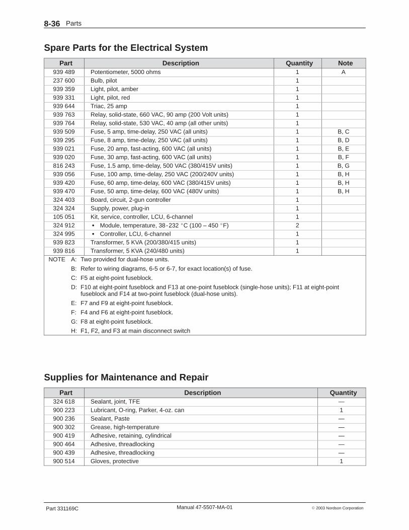
Spare Parts for the Electrical System
Part Description Quantity Note939 489 Potentiometer, 5000 ohms 1 A237 600 Bulb, pilot 1939 359 Light, pilot, amber 1939 331 Light, pilot, red 1939 644 Triac, 25 amp 1939 763 Relay, solid-state, 660 VAC, 90 amp (200 Volt units) 1939 764 Relay, solid-state, 530 VAC, 40 amp (all other units) 1939 509 Fuse, 5 amp, time-delay, 250 VAC (all units) 1 B, C939 295 Fuse, 8 amp, time-delay, 250 VAC (all units) 1 B, D939 021 Fuse, 20 amp, fast-acting, 600 VAC (all units) 1 B, E939 020 Fuse, 30 amp, fast-acting, 600 VAC (all units) 1 B, F816 243 Fuse, 1.5 amp, time-delay, 500 VAC (380/415V units) 1 B, G939 056 Fuse, 100 amp, time-delay, 250 VAC (200/240V units) 1 B, H939 420 Fuse, 60 amp, time-delay, 600 VAC (380/415V units) 1 B, H939 470 Fuse, 50 amp, time-delay, 600 VAC (480V units) 1 B, H324 403 Board, circuit, 2-gun controller 1324 324 Supply, power, plug-in 1105 051 Kit, service, controller, LCU, 6-channel 1324 912 � Module, temperature, 38-232 �C (100 – 450 �F) 2324 995 � Controller, LCU, 6-channel 1939 823 Transformer, 5 KVA (200/380/415 units) 1939 816 Transformer, 5 KVA (240/480 units) 1
NOTE A: Two provided for dual-hose units.
B: Refer to wiring diagrams, 6-5 or 6-7, for exact location(s) of fuse.
C: F5 at eight-point fuseblock.
D: F10 at eight-point fuseblock and F13 at one-point fuseblock (single-hose units); F11 at eight-pointfuseblock and F14 at two-point fuseblock (dual-hose units).
E: F7 and F9 at eight-point fuseblock.
F: F4 and F6 at eight-point fuseblock.
G: F8 at eight-point fuseblock.
H: F1, F2, and F3 at main disconnect switch
Supplies for Maintenance and Repair
Part Description Quantity324 618 Sealant, joint, TFE —900 223 Lubricant, O-ring, Parker, 4-oz. can 1900 236 Sealant, Paste —900 302 Grease, high-temperature —900 419 Adhesive, retaining, cylindrical —900 464 Adhesive, threadlocking —900 439 Adhesive, threadlocking —900 514 Gloves, protective 1