seismic guidelines for water pipelines march 2005 · 6.0 general pipeline design approach ......
TRANSCRIPT

AmericanLifelinesAlliance A public-private partnership to reduce risk to utility and transportation systems from natural hazards and manmade threats
Seismic Guidelines for
Water Pipelines
March 2005

AmericanLifelinesAlliance A public-private partnership to reduce risk to utility and transportation systems from natural hazards and manmade threats
Seismic Guidelines for
Water Pipelines
March 2005
www.americanlifelinesalliance.org
This report was written under contract to the American Lifelines Alliance, a public-private partnership between the Federal Emergency Management Agency (FEMA) and the National Institute of Building Sciences (NIBS). This report was prepared by a team representing practicing engineers in the United States water utility industry and academics.

Acknowledgements The following people and their affiliations contributed to this report.
Person Affiliation
John Eidinger (Chairman) G&E Engineering Systems Inc. Bruce Maison East Bay Municipal Utility District Luke Cheng San Francisco Public Utilities Commission Frank Collins Parsons Mike Conner San Diego Water Department Craig Davis Los Angeles Department of Water & Power Mike Matson Raines, Melton and Carella, Inc. Mike O'Rourke Rennselaer Polytechnic Institute Tom O'Rourke Cornell University Alex Tang Consultant John Wesling Geomatrix Consultants Inc. Mr. Doug Honegger provided technical oversight of this project. Mr. Joseph Steller (NIBS) provided project management for this project.
G&E would also like to thank the numerous staff of the San Francisco Public Utilities Commission, East Bay Municipal Utilities District, City of San Diego Water Department, the Los Angeles Department of Water and Power, and all the other participating agencies for their generous help.

Seismic Guidelines for Water Pipelines
Prepared for: National Institute of Building Sciences
As part of the:
American Lifelines Alliance
Prepared by:
G&E Engineering Systems Inc. 6315 Swainland Rd Oakland, CA 94611
(510) 595-9453 (510) 595-9454 (fax) [email protected]
Principal Investigator:
John Eidinger
G&E Report 80.01.01, Revision 0 March, 2005

Seismic Guidelines for Water Pipelines R80.01.01 Rev. 0
March, 2005 Page i
Table of Contents TABLE OF CONTENTS .................................................................................................................................... I
1.0 INTRODUCTION .........................................................................................................................................1
1.1 OBJECTIVE OF THE GUIDELINES..................................................................................................................1
1.2 PROJECT SCOPE............................................................................................................................................2
1.3 ABBREVIATIONS ..........................................................................................................................................2
1.4 LIMITATIONS................................................................................................................................................6
1.5 UNITS ...........................................................................................................................................................7
1.6 ACROBAT FILE FORMAT..............................................................................................................................7
2.0 PROJECT BACKGROUND........................................................................................................................8
2.1 GOAL OF SEISMIC DESIGN FOR WATER PIPELINES ....................................................................................8
2.2 FLOWCHARTS FOR THE THREE DESIGN METHODS.....................................................................................9
2.3 GUIDELINES CONTEXT ..............................................................................................................................12
3.0 PERFORMANCE OBJECTIVES.............................................................................................................13
3.1 PIPELINE CATEGORIES...............................................................................................................................13
3.2 PIPE FUNCTION CLASS...............................................................................................................................14
3.2.1 Pipe Function Class..........................................................................................................................14
3.2.2 Earthquake Hazard Return Periods ................................................................................................15
3.2.3 Other Function Class Considerations .............................................................................................16
3.3 OTHER GUIDELINES, STANDARDS AND CODES ........................................................................................18
4.0 EARTHQUAKE HAZARDS .....................................................................................................................20
4.1 TRANSIENT GROUND MOVEMENT ............................................................................................................21
4.2 LIQUEFACTION...........................................................................................................................................22
4.3 PERMANENT GROUND MOVEMENT ..........................................................................................................22
4.4 SEISMIC HAZARD ANALYSIS .....................................................................................................................23
4.4.1 Probabilistic Seismic Hazard Analysis (PSHA) .............................................................................24
4.4.2 Alignment Specific Evaluations .......................................................................................................28
4.5 FAULT OFFSET PGD ..................................................................................................................................31
4.6 LIQUEFACTION...........................................................................................................................................34
4.6.1 Liquefaction Induced Permanent Ground Movement ....................................................................36
4.6.2 Buoyancy ...........................................................................................................................................37
4.6.3 Settlement ..........................................................................................................................................37
4.6.4 Spatial Variation of Liquefaction PGDs .........................................................................................38
4.7 LANDSLIDE ASSESSMENT .........................................................................................................................38
5.0 SUBSURFACE INVESTIGATIONS........................................................................................................40
6.0 GENERAL PIPELINE DESIGN APPROACH......................................................................................43
6.1 INTERNAL PRESSURE .................................................................................................................................43
6.2 VERTICAL EARTH LOAD............................................................................................................................43
6.3 SURFACE LIVE LOAD.................................................................................................................................44
6.4 PIPE OVALIZATION ....................................................................................................................................46
6.5 FATIGUE .....................................................................................................................................................48
6.6 FLUID TRANSIENTS....................................................................................................................................48
7.0 ANALYTICAL MODELS..........................................................................................................................50
7.1 THREE MODELS, AND WHEN TO USE THEM.............................................................................................50
7.2 CHART METHOD ........................................................................................................................................50
7.2.1 Transmission Pipelines.....................................................................................................................51
7.2.2 Distribution Pipelines.......................................................................................................................52

Seismic Guidelines for Water Pipelines R80.01.01 Rev. 0
March, 2005 Page ii
7.2.3 Service Laterals and Hydrant Laterals ...........................................................................................53
7.2.4 Design Approach ..............................................................................................................................54
7.3 EQUIVALENT STATIC METHOD .................................................................................................................57
7.3.1 Analysis for Ground Shaking Hazard..............................................................................................57
7.3.2 Landslide and Liquefaction Permanent Ground Deformations.....................................................64
7.3.3 Analysis for Fault Crossing Ground Displacement Hazard .........................................................72
7.4 FINITE ELEMENT METHOD ........................................................................................................................74
7.4.1 Pipe Modeling Guidelines ................................................................................................................76
7.4.2 Soil Modeling Guidelines .................................................................................................................76
7.4.3 Wrinkling Limit .................................................................................................................................85
7.4.4 Tensile Strain Limit...........................................................................................................................87
8.0 TRANSMISSION PIPELINES..................................................................................................................88
8.1 SEISMIC DESIGN ISSUES RELATED TO TRANSMISSION PIPELINES ...........................................................88
8.1.1 Seismic Hazards and Geotechnical Assessment .............................................................................88
8.1.2 Pipe Materials and Wall Thickness .................................................................................................89
8.1.3 Design Earthquakes..........................................................................................................................89
8.1.4 Pipeline Alignment............................................................................................................................90
8.1.5 Soil Mitigation...................................................................................................................................90
8.1.6 Pipe Joints .........................................................................................................................................90
8.1.7 Pipe Structural Design and Analysis ...............................................................................................98
8.1.8 Pipe Supports ....................................................................................................................................99
8.1.9 Pipe Depth and Trench Backfill.....................................................................................................101
8.1.10 Pipe Bend and Thrust Block Design............................................................................................101
8.1.11 Design Features and Appurtenances...........................................................................................101
8.1.12 System Redundancy ......................................................................................................................103
8.1.13 System Modeling ...........................................................................................................................103
8.1.14 Corrosion Control ........................................................................................................................104
8.1.15 Internal Pressure and External Loads ........................................................................................105
8.1.16 Constructability.............................................................................................................................106
8.1.17 Economic Considerations ............................................................................................................106
8.1.18 Environmental Issues....................................................................................................................106
8.1.19 Public Relation or Outreach ........................................................................................................106
8.1.20 Emergency Response Planning....................................................................................................107
8.1.21 Security ..........................................................................................................................................108
8.1.22 Other Special Design Issues.........................................................................................................109
8.2 DESIGN CONSIDERATIONS AT FAULT CROSSINGS..................................................................................109
8.2.1 Fault Types and Fault Zones..........................................................................................................109
8.2.2 Orientation of Pipe with Respect to the Fault Line ......................................................................110
8.2.3 Design Earthquakes and Associated Magnitude of Fault Displacements ..................................110
8.2.4 Geotechnical Hazards ....................................................................................................................111
8.2.5 Soil-Pipeline Interaction ................................................................................................................111
8.2.6 Joints Used to Accommodate Fault Displacements......................................................................111
8.2.7 Analysis Methods ............................................................................................................................113
8.2.8 Design Redundancy ........................................................................................................................114
9.0 SUB-TRANSMISSION PIPELINES ......................................................................................................116
9.1 DESIGN USING THE CHART METHOD......................................................................................................116
9.2 FAULT, LANDSLIDE AND LIQUEFACTION ZONE CROSSINGS .................................................................117
Hazard Bypass System .............................................................................................................................117
9.2.1 Location of isolation valves for bypass relative to mapped hazard ............................................120
9.2.2 Bypass System Components ...........................................................................................................121
9.2.3 Coating System Details...................................................................................................................121
9.2.4 Purchase Specifications for Bypass System Components ............................................................122
9.2.5 Isolation Valve Approach Near Hazards ......................................................................................122
9.2.6 Automation of Isolation Valves ......................................................................................................122

Seismic Guidelines for Water Pipelines R80.01.01 Rev. 0
March, 2005 Page iii
9.3 AVOIDANCE/RELOCATION OF SUB-TRANSMISSION PIPELINE OUT OF HAZARD AREA ........................123
9.3.1 Fault Crossings ...............................................................................................................................123
9.3.2 Landslides........................................................................................................................................123
9.3.3 Areas of Potential Liquefaction .....................................................................................................124
9.4 LIQUEFACTION INDUCED SETTLEMENT ..................................................................................................124
9.4.1 Accommodating Settlements Using Semi-Restrained and Unrestrained Pipe............................124
9.4.2 Accommodating Settlements using Butt Welded Steel Pipe and Butt Fused HDPE Pipe..........124
9.5 SPECIALIZED FITTINGS AND CONNECTIONS ...........................................................................................125
10.0 DISTRIBUTION PIPELINES ...............................................................................................................132
10.1 CAST IRON PIPE .....................................................................................................................................133
10.2 DUCTILE IRON PIPE ...............................................................................................................................133
10.3 PVC PIPE ...............................................................................................................................................137
10.4 HIGH DENSITY POLYETHYLENE PIPE....................................................................................................138
10.5 PERFORMANCE OF COMMON PIPE JOINTS UNDER AXIAL LOADS .......................................................138
10.6 SEISMIC DESIGN RECOMMENDATIONS FOR DISTRIBUTION PIPELINES ...............................................139
10.7 STANDARD INSTALLATION BASED ON AWWA GUIDELINES..............................................................140
11.0 SERVICE AND HYDRANT LATERALS...........................................................................................145
11.1 TYPICAL CUSTOMER SERVICE AND FIRE HYDRANT LATERAL............................................................145
11.2 SEISMIC HAZARDS AND EFFECTS ON APPURTENANCES ......................................................................146
11.3 DESIGN FOR INERTIAL SEISMIC MOTIONS ...........................................................................................146
11.4 DESIGN FOR WAVE PROPAGATION GROUND STRAINS (PGV)............................................................148
11.5 DESIGN FOR PERMANENT GROUND DISPLACEMENT ...........................................................................148
11.5.1 Customer Services ........................................................................................................................149
11.5.2 Fire Hydrant Laterals...................................................................................................................149
12.0 OTHER COMPONENTS.......................................................................................................................156
12.1 EBAA IRON BALL JOINTS AT FAULT CROSSINGS................................................................................156
12.2 EQUIPMENT CRITERIA ...........................................................................................................................158
13.0 REFERENCES.........................................................................................................................................164
C1.0 COMMENTARY ....................................................................................................................................170
C1.1 OBJECTIVE OF THE GUIDELINES ...........................................................................................................170
C1.2 PROJECT SCOPE.....................................................................................................................................171
C1.4 LIMITATIONS .........................................................................................................................................171
C2.0 PROJECT BACKGROUND.................................................................................................................172
C2.2 HYDRODYNAMIC LOADING ..................................................................................................................172
C2.3 GUIDELINES CONTEXT..........................................................................................................................173
C3.0 PERFORMANCE OBJECTIVES........................................................................................................178
C3.1 CATEGORIES OF PIPELINES ...................................................................................................................178
C3.2 PIPE FUNCTION CLASS..........................................................................................................................179
C3.2.1 Pipe Function Class .....................................................................................................................179
C3.2.2 Earthquake Hazard Return Periods............................................................................................183
C3.2.3 Other Function Class Considerations ........................................................................................185
C3.3 OTHER GUIDELINES, STANDARDS AND CODES ...................................................................................191
C3.3.1 2003 International Building Code ..............................................................................................191
C3.3.2 ASCE 7-02. ...................................................................................................................................193
C3.3.3 1997 NEHRP provisions..............................................................................................................194
C3.3.4 1997 Uniform Building Code (UBC) ..........................................................................................194
C3.3.5 1997 JWWA Guidelines ...............................................................................................................195
C3.3.6 ASCE 1984....................................................................................................................................197
C3.3.7 ASCE-ASME 2001........................................................................................................................197
Seismic Guidelines for Water Pipelines R80.01.01 Rev. 0
March, 2005 Page iv
C3.3.8 PRCI 2004 ....................................................................................................................................197
C4.0 EARTHQUAKE HAZARDS ................................................................................................................198
C4.1 TRANSIENT GROUND MOVEMENT .......................................................................................................198
C4.2 LIQUEFACTION ......................................................................................................................................199
C4.3 PERMANENT GROUND MOVEMENT......................................................................................................200
C4.4 SEISMIC HAZARD ANALYSIS ................................................................................................................201
C4.4.1 Probabilistic Seismic Hazard Analysis (PSHA).........................................................................202
C4.4.1.1.1 Getting PGA and PGV...........................................................................................................204
C4.4.2 Design Level PGA and PGV Values ...........................................................................................205
C4.5 FAULT OFFSET ......................................................................................................................................210
C4.6 LIQUEFACTION ......................................................................................................................................213
C4.6.1 Simplified Method to Prepare a Regional Liquefaction Map ...................................................216
C4.6.2 Buoyancy ......................................................................................................................................220
C4.6.3 Settlement......................................................................................................................................220
C4.6.4 Spatial Variation of Liquefaction PGDs ....................................................................................221
C4.6.5 Application of Regional Liquefaction Map ................................................................................221
C4.7 LANDSLIDE ASSESSMENT .....................................................................................................................221
C4.8 GROUND MOTION PARAMETERS IN OTHER CODES.............................................................................226
C5.0 SUBSURFACE INVESTIGATIONS...................................................................................................228
C6.0 GENERAL PIPELINE DESIGN APPROACH.................................................................................228
C6.6 FLUID TRANSIENTS ...............................................................................................................................229
C7.0 ANALYTICAL MODELS.....................................................................................................................229
C7.1 THREE MODELS, AND WHEN TO USE THEM........................................................................................229
C7.2 CHART METHOD ...................................................................................................................................230
C7.2.1 Design Approach..........................................................................................................................230
C7.2.2 Distribution Pipelines ..................................................................................................................231
C7.2.4 Design Approach..........................................................................................................................231
C7.3 EQUIVALENT STATIC METHOD ............................................................................................................231
C7.3.1 Analysis for Ground Shaking Hazard .........................................................................................232
C7.3.2 Analysis for Landslide and Liquefaction Hazard ......................................................................234
C7.3.3 Fault Crossing Ground Displacement Hazard ..........................................................................240
C7.4.1 Pipe Modeling Guidelines ...........................................................................................................241
C7.4.2 Soil Modeling Guidelines ............................................................................................................242
C7.4.3 Wrinkling ......................................................................................................................................242
C7.4.4 Tensile Strain Limit......................................................................................................................243
C8.0 TRANSMISSION PIPELINES.............................................................................................................244
C8.1.2 Pipe Materials and Thickness .....................................................................................................244
C8.1.3 Design Earthquakes .....................................................................................................................245
C8.1.11 Isolation Valves..........................................................................................................................248
C8.1.14 Corrosion....................................................................................................................................248
C8.1.20 Emergency Response Planning .................................................................................................248
C8.2.3 Design Earthquakes and Associated Magnitude of Fault Displacements................................250
C8.2.6 Joints Used to Accommodate Fault Displacements...................................................................250
C8.2.7 Analysis Methods .........................................................................................................................250
C10.0 DISTRIBUTION PIPELINES ............................................................................................................251
C10.2 DUCTILE IRON PIPE.............................................................................................................................251
C11.0 SERVICE LATERALS........................................................................................................................252
C11.4 DESIGN FOR TRANSIENT SEISMIC GROUND STRAINS (PGV) ...........................................................252
C11.5 DESIGN FOR PERMANENT GROUND DISPLACEMENT ........................................................................252

Seismic Guidelines for Water Pipelines R80.01.01 Rev. 0
March, 2005 Page v
C11.5.2 Fire Hydrant Laterals................................................................................................................252
C12.0 OTHER COMPONENTS....................................................................................................................253
C12.2 EQUIPMENT CRITERIA ........................................................................................................................253
C13.0 REFERENCES......................................................................................................................................254

Seismic Guidelines for Water Pipelines R80.01.01 Rev. 0
March, 2005 Page 1
1.0 Introduction The Federal Emergency Management Agency (FEMA) formed in 1998 the American Lifelines Alliance (ALA) as a public-private partnership. In 2002, FEMA contracted with the National Institute of Building Sciences (NIBS) through its Multihazard Mitigation Council (MMC) to, among other things, assist FEMA in continuing the ALA guideline development efforts.
In 2004, NIBS contracted G&E Engineering Systems Inc. to develop these Guidelines for the seismic design of water pipelines.
1.1 Objective of the Guidelines Seismic design for water pipelines is not explicitly included in current AWWA standards. Compounding this problem, standard pipeline materials and installation techniques available to U.S. water utilities have shown themselves to be prone to high damage rates whenever there is significant permanent ground deformations (measured as PGD) or excessively high levels of ground shaking (measured as PGV).
The objective of these Guidelines is to provide a cost effective approach to seismic design of water pipelines, applicable throughout the United States. This means that there should be varying design requirements for different types of pipelines depending upon their overall importance to the network performance of the water utility and the localized risk of earthquakes.
The Guidelines are intended to be:
• Easy to implement. The Guidelines provide typical and seismic pipeline techniques commonly available to water utilities.
• Easy to understand. The Guidelines include practical examples. The Guidelines and commentary provide insight as to the assumptions embedded in the simplified design-by-chart, as well as guidance for detailed pipeline-specific design.
• Easy to use throughout the 50 United States. The Guidelines include methodologies that cover the entire 50 US states, both from the hazard and pipeline installation point of view.
• Easy to use by Small and Large Utilities. Many small water utilities have staffs of 20 or fewer people with perhaps 1 or 2 engineers. The largest water utilities may have staffs of several thousand people, with over 100 engineers. The Guidelines provide methodologies that can be used in both situations.
• Geared to be Cost Effective. The Guidelines are based on "performance based design" concepts, allowing individual utilities to select the seismic design approach that is cost effective for their particular situation at hand.

Seismic Guidelines for Water Pipelines R80.01.01 Rev. 0
March, 2005 Page 2
1.2 Project Scope The Guidelines provide three design methods for water pipelines. Each method is geared to provide suitable water-system-wide performance and post-earthquake recovery in a rare earthquake. In recognition that individual water utilities can have different priorities, available redundancy in their networks, emergency response capability, etc., the Guidelines allow the designer to modify the design requirements for individual pipelines to match local needs.
The Guidelines are intended to be used by water utility personnel, pipe designers and pipe manufacturers. The Guidelines are intended to be comprehensive. Given the wide possible variation in use, the Guidelines provide different design strategies for different situations. The general approach to implementing the Guidelines is as follows:
• Select the Function Class for each pipeline. I, II, III or IV. Section 3.
• Select the design method. Chart method. ESM method, FEM method. Sections 4, 5, 6, 7.
• Design the pipe. Category A, B, C, D or E. Sections 8, 9, 10, 11.
To quickly use these Guidelines, Section 2 provides flow charts that show each step of the design process, for several example situations.
The commentary provides additional background information. Implicit in the decision to use higher-cost pipelines is the question: "is it worth it?" The commentary provides an overview of the key factors that drive the seismic performance of water systems, covering economic losses due to water outages; fire following earthquake; the replace or repair issue for older pipes; and the economic life cycle of pipelines.
The Guidelines refer to three basic design methods. These are called the Chart Method, the Equivalent Static Method (ESM) and the Finite Element Method (FEM). In most situations, the pipeline designer need use only the Chart Method, and need not be concerned about the more analytical and more complicated ESM and FEM methods. By using the Chart Method, the designer should achieve the bulk of the seismic performance intended for good design.
Whichever method the designer uses, the Guidelines provide design solutions that are intended to be cost effective for the situation at hand.
1.3 Abbreviations ASCE American Society of Civil Engineers
ASME American Society of Mechanical Engineers
ALA American Lifelines Alliance
Seismic Guidelines for Water Pipelines R80.01.01 Rev. 0
March, 2005 Page 3
DLF Dynamic Load Factor
DSHA Deterministic Seismic Hazard Analysis
EBMUD East Bay Municipal Utility District
ESM Equivalent Static Method
FEM Finite Element Method
FEMA Federal Emergency Management Agency
G&E G&E Engineering Systems Inc.
GIS Geographical Information System
IBC International Building Code
JWWA Japan Water Works Association
LADWP Los Angeles Department of Water and Power
M Magnitude (moment magnitude)
MG Million Gallons
MGD Million Gallons per Day
MWD Maximum Winter Demand (MGD)
NEHRP National Earthquake Hazards Reduction Program
NEMA National Electrical Manufacturers Association
NIBS National Institute of Building Sciences
P Probability
PGA Peak Ground Acceleration, g
PGD Permanent Ground Displacement, inches
PGV Peak Ground Velocity (measured in inches/second)
PSHA Probabilistic Seismic Hazard Analysis
RR Equivalent Break Repair Rate per 1,000 feet of pipe
SA1 Spectral Acceleration at 1 second period
SCADA Supervisory Control and Data Acquisition
SFPUC San Francisco Public Utilities Commission
TCLEE Technical Council on Lifeline Earthquake Engineering
UBC Uniform Building Code
WTP Water Treatment Plant
Engineering Abbreviations and Units
A Cross sectional area of the pipeline, in2
AD Average surface fault displacement, m
B' Elastic support coefficient
bpf Blows per foot

Seismic Guidelines for Water Pipelines R80.01.01 Rev. 0
March, 2005 Page 4
c Seismic wave propagation speed in soil, feet/sec
cL Wave velocity, feet/second
C Cover depth of burial to the top of the pipeline, feet
Cf Component flexibility factor
Cg Grade mounting coefficient
Cp In structure amplification factor
d lateral offset distance from soil surface load to centerline of pipe
D Pipe diameter to inner wall thickness unless otherwise mentioned, inches
Dl Deflection lag factor
Dmax Maximum surface fault displacement, m
E Pipe material modulus of elasticity, psi
Fa NEHRP ground coefficient
Fv NEHRP ground coefficient
Fp Component design force, pounds
Fu Tensile (ultimate) stress, ksi
Fy Yield stress, ksi
FS Factor of Safety
g Acceleration of gravity, =32.2 feet / second / second
gpm gallons per minute
H Depth of burial to the spring line of the pipeline, feet
hw Depth of water table to the top of the pipeline, feet
hz Hertz (= cycles per second)
I Pipe wall moment of inertia (in4); importance factor
IA Arias intensity
K Bedding constant; bulk modulus of compressibility of water, psi
Ko Coefficient of lateral soil pressure
kV KiloVolt
kips Thousand pounds (kilo pounds)
km kilometer
ksi kips per square inch
L Length (feet or inches)
lb Pound
La Effective length between fault trace and an anchor point, feet
Lv Length from valve to open water surface, feet
Lp Length of pipe between segment joints, feet
LR Level of redundancy (Table 3-3)

Seismic Guidelines for Water Pipelines R80.01.01 Rev. 0
March, 2005 Page 5
m Meter
M Moment magnitude; benign moment in pipe, lb-feet
MD Maximum surface fault displacement
n number of joints in segmented/chained pipe that accommodate PGD
N, N1,60 Blow count form standard penetration test
Nc Soil downward bearing factor
Nch Soil transverse bearing factor (clay)
Ncv Soil bearing factor
Nqh Soil transverse bearing factor (sand)
Nqv Soil vertical bearing factor (sand)
p Pressure (psi)
pu Ultimate bearing force acting in transverse direction of pipe, pounds per inch of pipe length
pcf Pounds per cubic foot
psf Pounds per square foot
psi Pounds per square inch
P External pressure acting on the pipe; tensile force in pipe, kips
Pp Pressure transmitted to pipe from concentrated load
Ps Concentrated load on soil surface
Pv Vertical pressure acting on pipe
Py Yield force (kips)
qa Pipe allowable buckling pressure
qu Transverse (vertical upwards) soil spring, pounds/inch or kips/inch
qu Transverse (vertical downwards) soil spring, pounds/inch or kips/inch
r, R, ri Pipe radius (to inner steel wall), inches
R Closest distance to fault, km (other definitions of distance to fault are also used, as noted)
ro Pipe radius (to outer steel wall), inches
S Section modulus, in3
sec second
Su Undrained soil shear strength, psf
t Pipe wall thickness (inches)
tc Valve closing time (seconds)
tu Ultimate friction force acting in axial direction of pipe (pounds per inch of pipe length)
T Period (seconds)

Seismic Guidelines for Water Pipelines R80.01.01 Rev. 0
March, 2005 Page 6
V Shear force in pipe, kips
Vs Shear wave velocity, feet/sec (m/sec)
W Unit weight of water, =62.4 lb/ft3; or width of soil mass experiencing PGD, feet
xu Yield displacement of soil in axial (local-x) direction, inch
yu Yield displacement of soil in transverse (local-y) direction, inch
Z Free field design peak ground acceleration, g
zu Yield displacement of soil in vertical (local-z) direction, inch
Greek Symbols
Dimensionless factor in soil spring calculation; thrust angle
Acute angle between the fault line and the pipe centerline
Relative joint displacement, or PGD, inches
joint Displacement of joint in segmented pipe, inch
y Pipe vertical deflection
P Rise in water pressure due to rapid valve closure, psi
v Change in water velocity, feet/sec
allow Allowable strain (percent)
g Ground strain, estimate
pipe Peak longitudinal strain in the pipe
soil Peak strain in the soil
uu Ultimate uniform strain (percent)
d Soil dry unit weight, pcf
Soil effective unit weight, pcf
Seismic wave length in soil, feet
μ Poisson's ratio
bw Pipe through wall bending stress, psi
pipe Pipe stress, longitudinal direction, psi
y Yield stress, ksi
u Tensile (ultimate) stress, ksi
1.4 Limitations These Guidelines have been prepared in accordance with generally recognized engineering principles and practices. The Guidelines do not constitute a standard or code, and are not mandatory.

Seismic Guidelines for Water Pipelines R80.01.01 Rev. 0
March, 2005 Page 7
Each section of the Guidelines was prepared by one or more persons listed in the Acknowledgements. Each section has been reviewed by at least one or more other persons listed in the Acknowledgements. The utilities, companies and university affiliations listed in the Acknowledgements have all been gracious and helpful in supporting the development of the Guidelines; but their listing does not mean that they endorse the Guidelines.
The Guidelines should not be used without first securing competent advice with respect to its suitability for any general or specific application. The authors of the Guidelines, ALA, NIBS or FEMA shall not be responsible in any way for the use of the Guidelines.
1.5 Units This report makes use of both common English and SI units of measure.
Most water pipelines in the United States are sized by diameter using inches as the unit of measure. For example, distribution pipes are commonly 6-inch or 8-inch diameter. As these are nominal diameters, the actual measured diameter might vary, depending on lining and coating systems, pressure rating, pipe manufacturer and material. A conversion of a 6-inch diameter pipe to a 152.4 mm diameter pipe implies an accuracy that does not exist; a conversion of a 6-inch diameter pipe to be called a 150 mm diameter pipe implies that the pipe was purchased in a metric system, which in most cases it was not (at least in the United States). Thus, English units of measure are commonly used. SI units are also commonly used where they do not introduce inaccuracies.
For English units, we commonly use pounds and inches, although we sometimes use kips and feet.
Common Conversions
1 kip = 1,000 pounds
1 foot = 12 inches
1 inch = 25.4 mm
1 m = 1,000 mm
1.6 Acrobat File Format If you are viewing a .pdf version of this report, you must use Acrobat Reader version 7 (free from www.adobe.com). Prior versions of Acrobat may improperly display some fonts.

Seismic Guidelines for Water Pipelines R80.01.01 Rev. 0
March, 2005 Page 8
2.0 Project Background Seismic design for water pipelines is not explicitly included in current AWWA standards. Compounding this problem, standard pipeline materials and installation techniques available to U.S. water utilities have shown themselves to be prone to high damage rates whenever there is significant permanent ground deformations (measured as PGD1) or excessively high levels of ground shaking (measured as PGV).
These Guidelines address three situations:
• When the pipeline engineer has only a qualitative or limited quantitative estimate of the earthquake hazard, cannot do analyses, and wishes to rely on standardized pipeline components. The Guidelines call this the Chart Method.
• When the pipeline engineer wishes to perform a limited "equivalent static" type calculation to help design the pipelines, but when there are inadequate resources to perform detailed subsurface investigations, geotechnical engineering and pipe stress analyses. The Guidelines call this the Equivalent Static Method (ESM).
• When the pipeline engineer can perform detailed designs, including finite element analyses, and when the pipeline is so important that he can specify specialized components, materials and fabrication methods to be followed by the installation contractor. The Guidelines call this the Finite Element Method (FEM).
Whichever approach the pipeline engineer uses, these Guidelines provide design solutions that are intended to be cost effective2 for the situation at hand. To be cost effective, the design must account for the recurrence of the earthquake, the severity of the hazard, the fragility of the pipeline, the robustness of the system, and the consequences of failure.
2.1 Goal of Seismic Design for Water Pipelines The goal of this Guideline is to improve the capability of water pipelines to function and operate during and following design earthquakes for life safety and economic reasons. This is accomplished using a performance based design methodology that provides cost-effective solutions and alternatives to problems resulting from seismic hazards. Improved water pipeline performance will help create a more resilient community for post-earthquake recovery, which is the ultimate reason why water pipelines are considered for improvement. Therefore portions of the Guidelines inherently consider the community impacts if pipeline damage were to occur. The Guidelines do not intend to
1 PGD, as used in the Guidelines, refers to permanent ground deformations, and not peak ground
displacements. 2 See Commentary Section C1.1 for the meaning of "cost effective".

Seismic Guidelines for Water Pipelines R80.01.01 Rev. 0
March, 2005 Page 9
prevent all pipelines from being damaged. Rather, it is recognized that earthquakes may cause some limited and manageable pipe damage.
The Guidelines are aimed at helping the pipeline designer to strengthen the pipeline network so that the water system as a whole does not create a life safety problem and contain economic losses to manageable levels.
The Guidelines are applicable for both new installations and replacement of older pipes. The decision to replace old pipes is a complex one. Replacing older 4-inch to 10-inch diameter cast iron pipes solely on the basis of earthquake improvement is not recommended, and this is not commonly cost effective. However, as old pipeline are thought to need replacement because they no longer provide adequate fire flows, or have been observed to require repair at a rate of more than once every 5 years, then the added benefit of improved seismic performance may help justify the pipe replacement. Replacement of larger diameter pipelines (12-inch and upwards) may be cost effective strictly from a seismic point of view, in areas prone to PGDs.
The Guidelines only pertains to the water conveying pipelines. With the exception of equipment commonly used in pipe valve vaults, and anchorage of this equipment (Section 12), the seismic design for appurtenant facilities, such as tanks and pumping stations, etc. are not covered herein, but may directly affect the ability for the pipeline to function and are therefore recommended to be prudently designed consistent with this pipeline design Guidelines.
2.2 Flowcharts for the Three Design Methods Figures 2-1, 2-2 and 2-3 provide flowcharts of the general design process using each of the three design methods. In these flowcharts, the key part of the Guidelines is listed that gives the quantified procedures. The user should review the entire Guidelines and Commentary to appreciate the complete design process.
Any step in the flowcharts can be modified to reflect additional information, refined procedures or other considerations that the designer feels appropriate.
The flowcharts do not highlight any design steps needed for non-seismic design. Some of the common non-seismic design issues are outlined in Section 6 and elsewhere in the Guidelines; but the Guidelines are not meant to provide complete or comprehensive non-seismic design guidance.
The flowcharts do not highlight seismic design for hydrodynamic loading. The Guidelines recommend that such loads be considered, especially for segmented pipelines. Comprehensive design tools do not yet exist to quantify hydrodynamic loading. The Guidelines provide suggestions as to how to treat these loads.

Seismic Guidelines for Water Pipelines R80.01.01 Rev. 0
March, 2005 Page 10
Figure 2-1. Flowchart for Chart Method

Seismic Guidelines for Water Pipelines R80.01.01 Rev. 0
March, 2005 Page 11
Figure 2-2. Flowchart for Equivalent Static Method

Seismic Guidelines for Water Pipelines R80.01.01 Rev. 0
March, 2005 Page 12
Figure 2-3. Flowchart for Finite Element Method
2.3 Guidelines Context The Guidelines were developed to address the observation that too many water pipes are breaking in earthquakes, and that extensive pipe breakage has the potential to lead to great economic harm to our urban communities. Since the early 1990s, the Technical Council on Lifeline Earthquake Engineering (TCLEE) has produced a series of monographs addressing the performance of water systems in earthquakes. Some of these include: Fire Following Earthquake (Scawthorn, Eidinger, Schiff, 2005), Seismic Screening Checklists for Water and Wastewater Facilities (Heubach, 2003), and Guidelines for the Seismic Upgrade of Water Transmission Facilities (Eidinger and Avila, 1999).
Soon after the Great Hanshin (Kobe) earthquake of 1995, with its widespread damage to buried water pipelines, substantial impact of fires and 10 week time to restore water to Kobe, many Japanese and American water utilities got together to figure out "what is going wrong" and "what should be done about it". Two important outcomes were the development of a Japanese seismic design guideline for water systems (JWWA 1997) and four joint Japan-American workshops to address seismic issues for water utilities. The commentary provides further background about these activities, and how they have been considered in context of these Guidelines.

Seismic Guidelines for Water Pipelines R80.01.01 Rev. 0
March, 2005 Page 13
3.0 Performance Objectives The seismic design of pipelines and their appurtenances should3 be based on the intended operational performance level the system must achieve in a post-earthquake disaster situation. This requires seismic Performance Objectives to be selected for the system. The Performance Objectives consist of one or more performance goals. Each performance goal consists of two parts:
• Target Performance Level
• Seismic Hazard Level
From the performance goals, each pipeline is identified according to an operational performance reliability. The function of the pipeline within the system defines its importance in achieving the system performance goal and its needed reliability.
3.1 Pipeline Categories Each pipeline should have a target performance level.
The Guidelines provide the following definitions for a "pipeline". These definitions are meant only as a way to provide a common point for communication. For example, one utility's "trunk line" might be another utility's "transmission line" and may be another utility's "aqueduct". If the user wishes to use an alternative definition, then the user may also make corresponding changes in other parts of the Guidelines.
• Transmission pipelines. These are pipelines with nominal diameters from 36-inch to 120-inch (or larger). A transmission pipeline will often deliver water at a rate of 30 MGD to 300 MGD, typically sufficient to serve a population of 100,000 to more than 1,000,000 people. Transmission pipelines are often used for both potable or raw water conveyance.
• Sub-transmission pipelines. These are pipelines with nominal diameters from 16-inch to 30-inch. A sub-transmission pipeline will often deliver water at a rate of 5 MGD to 30 MGD, typically sufficient to serve a population of 10,000 to 100,000 people. Sub-Transmission pipelines are often used for both potable or raw water conveyance.
• Distribution pipelines. These are pipelines with nominal diameters from 6-inch to 12-inch. A distribution pipeline will often deliver water at a rate from under 0.1 MGD to 5 MGD. A 6-inch distribution pipeline could serve a single city street, supporting a population of perhaps a few tens of people. A 12-inch distribution
3 The terms "should", is used in the Guidelines. The Guidelines are not a code or standard, and
everything in the Guidelines is non-mandatory.

Seismic Guidelines for Water Pipelines R80.01.01 Rev. 0
March, 2005 Page 14
pipeline could be part of a grid, with many redundancies, serving a population of a few thousands of people. Distribution pipelines are almost exclusively used for potable water conveyance.
• Service and hydrant laterals. Service laterals are small diameter pipelines that take water from a distribution pipeline to a single structure (in some cases, split to a few structures). Service laterals are often 5/8-inch to -inch diameter, when delivering water to a single family residential structure; or could be as large as a few inches in diameter when delivering water to a commercial, industrial or other large quantity user. A hydrant lateral is a 6-inch (typical) diameter pipe branching off a distribution pipeline, and ending at a fire hydrant, standpipe, or blow off assembly. Air and vacuum release valve assemblies can also be attached to distribution, sub-transmission or transmission pipelines using small diameter pipes. Laterals are almost exclusively used for potable water conveyance.
Pipelines can be as short as a few feet long (like a service or hydrant lateral) or as long as tens to hundreds of miles (like transmission pipelines). As described in the Guidelines, the intent is to design these pipelines to meet a specific level of performance under earthquake conditions. The target reliability of an individual pipeline will therefore require an understanding of the length of the pipeline, as well as the type of earthquake hazards traversed by the pipeline.
3.2 Pipe Function Class 3.2.1 Pipe Function Class
Each pipeline's target performance under earthquake conditions is related to its intended function and importance. For example, the pipelines that provide water for fire suppression serve a more important function for post-earthquake response than those that provide irrigation water, regardless of their size and capacity. As a result, pipelines providing water for fire suppression are intended to perform at a higher level under seismic conditions than those simply used for irrigation.
Table 3-1 classifies pipes into four functions related to their importance in improving a community's post-earthquake response and recovery. The Commentary provides guidance on how to classify pipes as Function Class I, II, III, or IV based on how critical they are and consequences of failure, with consideration of: the facilities they serve; importance to the community for fire fighting, health, and post-earthquake emergency response and recovery; potential for secondary disasters (erosion, inundation, life safety) resulting from pipe damage or failure; difficulty in making repairs; effects on community socio-economics; and a pipe's ability to disrupt emergency response or evacuation if damaged.

Seismic Guidelines for Water Pipelines R80.01.01 Rev. 0
March, 2005 Page 15
Pipe Function Class
Seismic Importance Description
I Very low to None Pipelines that represent very low hazard to human life in the event of failure. Not needed for post earthquake system performance, response, or recovery. Widespread damage resulting in long restoration times (weeks or longer) will not materially harm the economic well being of the community.
II Ordinary, normal Normal and ordinary pipeline use, common pipelines in most water systems. All pipes not identified as Function I, III, or IV.
III Critical Critical pipelines serving large numbers of customers and present significant economic impact to the community or a substantial hazard to human life and property in the event of failure.
IV Essential Essential pipelines required for post-earthquake response and recovery and intended to remain functional and operational during and following a design earthquake.
Table 3-1. Pipe Function Classes
Pipelines in Functional Use Group I can be constructed using "standard" design, where "standard" means that all non-seismic load conditions must be considered, but no seismic condition need be considered.
3.2.2 Earthquake Hazard Return Periods
For operational purposes, a pipeline should have a minimum performance reliability following an earthquake. The need for operational reliability in any given pipe increases with increasing functional importance. For seismic design, the reliability of a pipe being operational following an earthquake will depend upon the margin of safety built into the pipeline design, given that the pipe experiences a particular level of earthquake hazard. The Guidelines consider pipe reliability in relation to a time period t, where t identifies the time basis for facility design. A 50-year design basis is listed in Table 3-2 to be consistent with standard engineering practice, although many pipes will last for much longer time. Table 3-2 identifies the recommended earthquake hazard return period for each pipe Function Class.
Pipe Function
Class Probability of Exceedance P
in 50 years
Return Period T
(years) I 100% Undefined II 10% 475 III 5% 975 IV 2% 2,475
Table 3-2. Earthquake Hazard Return Period for each Pipe Function Class
The return period in Table 3-2 identifies the average time between design-level seismic hazard occurrences. In some cases, the owner may wish to establish the reliability of the pipeline given that an earthquake of a particular return period, or a deterministic scenario earthquake occurs. Return period is important when the engineer (owner) is concerned with annualized losses from earthquakes.

Seismic Guidelines for Water Pipelines R80.01.01 Rev. 0
March, 2005 Page 16
3.2.3 Other Function Class Considerations
The pipe function classification and corresponding seismic design level are specific to individual water supply and distribution systems. The following seismic design provisions allow customization of the recommendations in these Guidelines for specific system conditions. These provisions also allow owners to consider cost-effective options in water system seismic improvements through use of redundancies, isolation capabilities, emergency response, etc. as alternatives to hardening specific pipelines.
3.2.3.1 Multiple Use Pipelines
Pipelines providing water service for multiple uses are recommended to be classified under the highest corresponding Function Class in Table 3-1. Where pipe connections and branches come from a higher Function pipeline to serve a lower Function, the branch pipe is recommended to be designed as the higher Function; alternatively, if damage or failure of the branch pipe can be shown not to affect the ability for the higher Function pipe to provide the necessary water service, then the branch pipe may be designed for its intended Function.
3.2.3.2 Continuity
Pipelines and pipeline systems are recommended to be designed for the higher Function for which service is provided from the supply and water treatment source to the point of service. This includes all transmissions pipes, sub-transmission pipes, distribution pipes, and service lateral and hydrant laterals. In many cases the water distributor (sometimes called wholesaler) is only responsible to the point of service connection, usually at a meter connection. Beyond the service connection, the next owner (retail customer) is responsible for the pipe. The water wholesaler and property owner are each responsible for their respective portions of the system to ensure continuity of design, construction, and maintenance to be consistent with designated pipeline Function.
Many water systems receive potable and raw water supplies from wholesale water agencies. For purposes of these Guidelines, systems receiving water from wholesalers are defined as retail agencies. Pipelines providing the wholesale water supplies to the retailer are considered an extension of each retail supply and distribution system and are therefore subject to the same continuity recommendations as all pipes within a retail system. Wholesale pipelines serving urban retailers may generally be classified as Function IV pipes (if non-redundant) unless retailers are shown not to have a need for Function IV supply pipelines. The retailers and wholesalers are each responsible for their respective pipelines and appropriate communication is recommended for both parties to ensure proper continuity for the retailer.
3.2.3.3 Supply Source
For the purposes of these Guidelines, a supply source is defined as a source that provides the minimum normal and/or emergency water supplies to the community it is intended to serve. A source may be one or combination of open or covered reservoirs, tanks,

Seismic Guidelines for Water Pipelines R80.01.01 Rev. 0
March, 2005 Page 17
groundwater supplies, river intakes, aqueduct intakes, etc. that together meet the minimum water supply requirements. If multiple sources are used in combination to meet the minimum supply requirements, each individual supply source should be taken as a source and be classified with the appropriate pipe Function.
3.2.3.4 Redundancy
Redundant pipelines increase the reliability of post-earthquake operations, provided the redundancy meets the following criteria:
1. A leak or break in one pipe will not likely lead to damage on other redundant pipes; and
2. All redundant pipes can provide a minimum needed flow to meet post-earthquake operational needs. The minimum level of flow required after earthquakes should generally be at the maximum winter time flow rate, or a level of water that is sufficient for household and most economic activities of the community; and
3. The redundant pipes are spatially separated by an adequate distance through potential ground deformation zones (landslide, fault movement, ground failure, lateral spreading, etc.) such that, should ground deformation occur, each redundant pipe may not be subjected to the same amount of ground movement due to the natural variation in movement across a deformation zone, regardless of the actual design parameters.
Pipelines meeting the above requirements may have their Functions reclassified as shown in Table 3-3 in terms of the level of redundancy LR. There is no redundancy at LR=0. For one redundant pipeline, LR=1. For two or more redundant pipelines, LR=2.
Pipe Function LR = 0 LR = 1 LR = 2 I I I I II II II II III III II II
IV IV III II
Table 3-3. Function reclassification for redundant pipes.
3.2.3.5 Branch Lines and Isolation
Supply and distribution pipelines often have other supply lines, distribution lines, and service connections branching from them. Post-earthquake reliability may be compromised in pipes having branching lines that are designed to a lower functional class. To ensure post-earthquake operational reliability the following procedure is recommended for evaluating branch pipe design requirements and isolation capability. This procedure is only applicable to pipelines of a lower Function branching from pipes of a higher Function.

Seismic Guidelines for Water Pipelines R80.01.01 Rev. 0
March, 2005 Page 18
1. Determine the Function for the branch pipe using Table 3-1. 2. Determine the Function of the pipe it is branching from. 3. Design the branch pipe for:
a. The lower Function if: i. Isolation valves are installed and the time needed to close these
valves (whether manual or automatic) is acceptable with regards to post-earthquake response and recovery; or
ii. An engineering analysis is performed and shows the branch pipe(s) will not disrupt post-earthquake performance of the higher pipe Function. This evaluation must account for the cumulative effect of potential damage on all branch pipes.
b. The higher function if (a) is not satisfied.
3.2.3.6 Maintenance
One of the greatest seismic mitigations for water pipelines is proper maintenance to ensure pipeline seismic performance. All pipes must be maintained to ensure their proper seismic performance for their Functional Class.
3.2.3.7 Damage and post earthquake repair
These Guidelines are not intended to completely eliminate all seismic induced pipe damage for Function Class II, III and IV pipelines, but it will significantly reduce the damage and post-earthquake recovery time. In addition, the ability for the system to perform during and following an earthquake will be significantly improved. Therefore, it is important for organizations that operate water system pipelines to have adequate capabilities to respond to a design earthquake and make repairs.
3.2.3.8 Earthquake preparedness and response plans
Waterworks organizations are recommended to develop and maintain seismic preparedness and response plans that incorporate methods to respond to and repair pipeline damage following an earthquake. Emergency Operations Centers for non-water works organizations and other non-water critical facilities are encouraged to develop their own emergency preparedness pans that factor in the availability of rapid restoration of water supply post-earthquake.
3.3 Other Guidelines, Standards and Codes Various codes, standards and guidelines already exist that are commonly used for the seismic design of buildings and related facilities, as well as a few that address welded steel pipelines. Many of these were reviewed to assess their possible application for the seismic design of water pipelines. The commentary presents a summary of this review.
Through 2004, there have been de facto no seismic requirements for the design and installation of water pipelines used in the United States. Nationwide codes such as UBC and IBC sometimes touch on the issue, but effectively no one looks to these codes for

Seismic Guidelines for Water Pipelines R80.01.01 Rev. 0
March, 2005 Page 19
guidance on seismic design of water pipelines. Industry organizations such as AWWA, and ASTM are essentially silent on seismic design of water pipelines.
Some water utilities have developed internal (utility-specific) engineering standards of practice that cover seismic design requirements. Some of these utility-specific practices (notably EBMUD) were examined as part of preparation of these Guidelines.
Following the 1995 Kobe earthquake in Japan, the Japan Water Works Association (JWWA) developed a set of seismic design guidelines for water systems. These guidelines are non-mandatory for new installations, but are often (not always) adopted within context of available water utility budgets. Since 1995, many large water utilities in Japan have instituted far reaching and expensive seismic retrofit programs, with consideration of these guidelines. These JWWA guidelines were considered as part of preparation of these Guidelines (see C3.3.5).

Seismic Guidelines for Water Pipelines R80.01.01 Rev. 0
March, 2005 Page 20
4.0 Earthquake Hazards In order to use any of the design approaches described in these Guidelines, the user will generally need to establish suitable PGA (for above ground installations), PGV (for below ground installations) and PGD (some of the time) values for the pipeline. The computation of PGD may also require knowledge of PGA and duration of shaking and other factors.
Section 4.0 provides guidance to do this in a simplified manner using widely available data sources. The Commentary provides additional refinements. Often times, the guidance presented in these Guidelines may not be sufficient, and project-specific input from a geosciences expert will need to be retained.
The primary earthquake hazards of concern for water pipes are transient and permanent ground movements. Tsunami poses a hazard along coastal regions, especially for above ground pipes, but will not be addressed further in this report. Buoyancy may affect a pipeline where there is an increase in subsurface pore water pressure, especially in areas prone to liquefaction.
Transient ground movement describes the shaking hazard by waves propagating from the energy source and the amplifications due to surface and near surface ground conditions and topography. Permanent ground movement describes the ground failures resulting from surface fault rupture, slope movements and landslides, liquefaction induced lateral spreading and flow failure, and differential settlement. Table 4-1 summarizes the transient and permanent ground movement hazards considered in these Guidelines that may damage water pipelines, the earthquake parameters needed for an engineering evaluation for each hazard, recommended methods for obtaining the earthquake parameters, and geotechnical parameters needed for a proper engineering evaluation of the earthquake hazard.
The purpose of this section is to identify the earthquake hazards a water pipeline may be exposed to that are of concern, provide a general description of how the hazard affects pipelines, and define the parameters needed to quantify the earthquake hazards for engineering design. The following sections provide recommendations for performing geotechnical investigations and evaluations to assess the true exposure and level of concern, if any, different earthquake hazards have on water pipelines.

Seismic Guidelines for Water Pipelines R80.01.01 Rev. 0
March, 2005 Page 21
Hazard Earthquake Parameters
Obtain from: Geotechnical Parameters
Transient Ground Movement
General Shaking pga, pgv, spectral response
PSHA Soil/rock conditions, depth, Vs
Near-source directivity
Fault distance PSHA, fault map Fault type, orientation, rupture direction
Ground amplification
pga, pgv , spectral response
PSHA Site soil and rock conditions, Vs
Permanent Ground Movement
Faulting Magnitude, length Deaggregate PSHA or geologist
Fault type, orientation
Liquefaction pga, magnitude PSHA, deaggregate Soil type, relative density, thickness, groundwater
Lateral spread and Flow failure
pga, magnitude, distance PSHA ,deaggregate Topography, soil type, strength, thickness,
groundwater Slope movement,
landslide pga, acceleration time
history PSHA Topography, ground
strength, groundwater Settlement pga PSHA Soil type, strength,
thickness, groundwater
Table 4-1. Earthquake hazards and parameters needed for pipeline design
The performance of buried pipelines is largely governed by the induced ground strains. Transient ground strains are generally smaller than those from permanent ground deformation. A proper pipeline evaluation will consider effects from all potential strain sources.
4.1 Transient Ground Movement Ground shaking presents the greatest hazard exposure because it occurs in all earthquakes and may result from many different earthquake sources. The transient wave amplitudes are dependent upon source energy release, distance from the source, the materials that wave propagate through between the source and pipe, near surface conditions, and local topography. The ground shaking amplitude and distance of felt effects generally increases with increasing earthquake magnitude. Shaking within 15 km from the earthquake source involves near-source ground motions associated with forward and reverse directivity. Forward directivity involves large velocity pulses of relatively long period propagating in the direction of rupture, and reverse directivity involves motion with a longer duration propagating away in a direction opposite to that of fault rupture (Somerville and Graves, 1993). Near-source motions can create large ground strains that might be large enough to sometimes damage non-seismically-designed segmented pipe.
Local near-surface ground conditions can amplify transient motions. Amplifications result as the seismic waves propagate from conditions of higher shear wave velocity Vs (higher stiffness) into materials of lower Vs (lower stiffness). These conditions occur in weathered and fractured rock and soils. The relative amplifications are dependent upon

Seismic Guidelines for Water Pipelines R80.01.01 Rev. 0
March, 2005 Page 22
the relative Vs (Schnable, 1972). Weaker soils may deamplify ground motions when the ground strains exceed the available soil strength (Idriss, 1990). Large transient strains may result at interfaces of different materials, called impedance boundaries, due to changes in wave propagation speed.
4.2 Liquefaction Liquefaction is the loss of shear strength, and corresponding reduction in effective stress, in saturated or nearly saturated soils due to shaking induced pore water pressure increases. It is the effects of liquefaction that pose a hazard to pipelines, rather than the actual liquefaction phenomena. Pore water pressure increases can impose buoyancy on buried pipelines, which if not properly accounted for may lead to pipe floatation and possible damage.
The loss of soil shear strength can lead to large permanent ground strains. Permanent ground movements are manifested through lateral spreading, flow failure, and settlement. Lateral spreading is the down slope movement occurring when cyclic inertial loads exceed the reduced effective soil strength and is generally associated with shallow surface ground slopes (as low as a fraction of a percent slope). Flow failure is a slope instability problem resulting when the static shear stresses in sloping ground exceed the liquefied soil residual strength. Liquefaction induced settlements are generally larger than non-liquefaction settlements. Reductions in soil bearing strength may also cause problems for above ground pipes.
Liquefaction may also induce pipe flotation, especially empty pipes commonly used in sewer systems. Flotation has not been a common source of damage for water pipelines, as they are rarely (if ever) empty.
4.3 Permanent Ground Movement Permanent ground movements pose the greatest hazard for pipelines, even though they are more localized and involve less exposure to pipelines than transient movements. The significance of this hazard is related to the large ground strains resulting from permanent movements. Strains induced by permanent ground deformation will be the largest at the movement boundaries. For liquefaction, this occurs at the interface between liquefied and non-liquefied materials; for faulting it occurs at the primary trace of surface rupture; for landslides it occurs at slide boundaries; for settlement the greatest hazard results at locations of greatest differential settlement.
Surface faulting may occur on earthquake-generating faults or as sympathetic movement on nearby faults. Fault rupture generally occurs over a zone with largest movements resulting on a main trace and other fractures with movements of concern occurring at distances away from the main trace. The total magnitude of surface rupture and width of rupture zone is a function of earthquake magnitude, with larger movements generally occurring with larger magnitudes, and with the zone of deformation usually dependent on the local nature of the fault.

Seismic Guidelines for Water Pipelines R80.01.01 Rev. 0
March, 2005 Page 23
Slopes stable under static conditions may be destabilized under seismic shaking as a result of induced inertial forces. The steeper the slope and weaker the resisting planes, the more susceptible to movement the slope becomes. The presence of groundwater increases the slope movement potential through increased pore water pressure and reduced effective stress. Landslides generally refer to a broad category of failures including earth slides, rock falls, slumps, and debris flows. Earth slides may result in movements from a few millimeters to several tens to hundreds of meters. Smaller deformations are generally referred to as slope movements and larger movements as slope failures or just landslides. Rock falls are rarely a problem for buried pipes.
Settlement results from the densification of relatively loose, partially saturated or dry granular soils. Settlement increases with decreasing relative density and fines content. Settlement also occurs as a consequence of liquefaction in saturated granular soil, and will again increase with decreasing relative density and fines content (Ishihara and Yoshimine, 1995; Tokimatsu and Seed, 1987). Settlement resulting from densification is the surface manifestation of volumetric strain, which is directly related to the total thickness of loose and/or liquefiable soil layers. The hazard to pipelines occurs where the greatest differential settlement results.
Settlement may also occur as a result of subsurface erosion and ejection of soil at sand boils, fissures, and cracks in the ground overlying soil subjected to liquefaction. This type of settlement is related to the localized loss of material through ejection and venting of particles carried by water at elevated pressure. It may be accompanied by large differential settlement in the form of surface depressions and sink-hole-like manifestations of surface movement. Such deformation generally occurs in soil deposits subjected to prolonged and severe liquefaction. It involves larger levels of settlement than those associated with densification, as described above. Sometimes, movement of this sort is accompanied by large lateral displacements, which represent a more severe condition of deformation for underground pipelines. Under these conditions then, it will generally be appropriate to concentrate on the effects of large lateral soil movement, as addressed under Section 4.2.1.
Soil deformations due to soil failure (including weak clay deformations in peat, bay mud and similar situations) may also occur.
4.4 Seismic Hazard Analysis The definition of the earthquake hazards along a pipeline alignment must be performed as part of the seismic design process. The pipe alignment must be assessed to determine which of the earthquake hazards described in Sections 4.0 to 4.3 and in the commentary may affect the pipes seismic performance. An analysis of the hazards may be performed using probabilistic or deterministic seismic hazard analyses (PSHA and DSHA, respectively). Advantages and disadvantages to PSHA and DSHA in pipeline evaluations are presented in the commentary. The PSHA is used in these Guidelines for defining the hazard for single pipes extending over relatively short distances.

Seismic Guidelines for Water Pipelines R80.01.01 Rev. 0
March, 2005 Page 24
DSHA is useful when examining the performance of a complete pipeline network over a spatially large area. A "scenario" earthquake is an example of a DSHA. For spatially distributed pipeline systems, the PGA (as well as SA, PGV, PGD) at one site will be different from the PGA at some distant site, all associated with a particular scenario earthquake. For this reason, water utilities often resort to study using deterministic "earthquake scenarios" rather than probabilistic earthquakes. For larger water utilities that cover areas of hundreds of square miles, use of earthquake scenarios for evaluations (and sometimes design) can be a suitable approach. For smaller water utilities that cover a few tens of square miles, or for some situations in eastern United States where ground motions vary little in intensity over wide areas, then a probabilistic-based approach (i.e., a return-period approach) will be almost the same as a deterministic approach. For these Guidelines, we adopt a probabilistic approach, with the understanding that the user could adjust to a deterministic approach, as long as the intended performance (C3.2.3.7) of the pipeline network is achieved.
4.4.1 Probabilistic Seismic Hazard Analysis (PSHA)
Results of the PSHA will provide a consistent set of seismic design parameters having a uniform probability that each parameter will not be exceeded. As shown in Table 4-1, many seismic design parameters can be obtained from a PSHA. The USGS has an interactive deaggregation web page for performing site-specific4 PSHA, which is accessible on the World Wide Web at: http://eqint.cr.usgs.gov and is recommended for use with these Guidelines. The user can replace the USGS PSHA information with user-developed corresponding information.
Figure 4-1 shows the USGS data entry page. A PSHA may be performed for a pipeline by inputting the following information:
1. Site name. 2. Site coordinates (latitude, longitude). 3. Selection of return period. 4. Selection of pga or spectral acceleration frequency.
4 The PSHA values on the USGS web site are calculated at specific latitude/longitude pairs. Thus,
the term "site-specific" is not quite rigorous if the user inputs a latitude/longitude pair that is not atop one of the calculated values, as the USGS web site does interpolation for intermediate locations. Usually, the results from the USGS web site will be within 10 percent of a true site-specific calculation. Also, the calculation procedure on the USGS web site is based on data and methodologies that may become outdated over time, as new information is developed with regards to fault activity, fault location, attenuation models, and other facets of a truly site-specific calculation. A qualified professional can perform a PSHA and use that result rather than the USGS web site result.

Seismic Guidelines for Water Pipelines R80.01.01 Rev. 0
March, 2005 Page 25
Figure 4-1. USGS data entry for interactive deaggregation showing data input for site
“Pipe Example.”
Descriptions for the input needed for Figure 4-1 are provided on the USGS web site.
To obtain the necessary parameters shown in Table 4-1 for Function II, III, and IV pipes, a PSHA for 2, 5, and 10% probability of exceedance in 50 years for PGA and 1.0 hz spectral acceleration will need to be performed. If a response spectrum is needed for above ground pipes, additional PSHA at desired spectral accelerations can be performed. Several PSHA may need to be performed depending on the relative number of active faults and close proximity to the pipe, the number of different earthquake hazards as identified in Table 4-1, the length of pipe, and other pertinent parameters.

Seismic Guidelines for Water Pipelines R80.01.01 Rev. 0
March, 2005 Page 26
Figure 4-2 shows a standard results page obtained by clicking the "generate plot(s) and data" button in Figure 4-1. Standard deaggregation results are presented in the form of a Probabilistic Seismic Hazard Deaggregation plot and a table. The plot may be copied from the web page in .gif, .pdf, or .ps format. The hazard matrices present numerical results of the PSHA. Data may be downloaded using File Transfer Protocol (FTP). Additional results obtained in the form of an additional plot if the “Yes” button, shown in Figure 4-1 bottom left, is checked for graphic deaggregation.
Figure 4-2. Interactive deaggregation output page.
Figure 4-3 presents results of a probabilistic seismic hazard deaggregation. The site is “Pipe Example” at latitude and longitude coordinates of -120.000o longitude and 40.000o latitude, as per Figure 4-1. “This PSHA is for a Function Class IV pipeline and was therefore evaluated for a PGAB having a 2% chance of exceedance in 50 years (2,475 year mean return time). PGAB identifies the peak ground acceleration on a ground class B, as defined in the next section. Statistics of the PSHA are presented in the upper right

Seismic Guidelines for Water Pipelines R80.01.01 Rev. 0
March, 2005 Page 27
side of Figure 4-3 showing the site has a PGAB = 0.63g. Additional deaggregation information includes mean and modal fault distance R and magnitude M. The bar plot in Figure 4-3 presents M vs R with the vertical bar showing the relative contribution of different seismic sources to the hazard. Figure 4-3 shows the seismic parameters for a 2% chance of exceedance in 50 years are bound with a mean PGAB of 0.63g occurring at site “Pipe Example” resulting at a mean hypocentral distance of R=6.1 km from the site with a characteristic magnitude M = 6.7; the modal distance ranges between 4.9 and 5.2 km with a characteristic magnitude of 6.8. For this site it would be reasonable to select R=5.0 km and M=6.8.
Figure 4-3. Probabilistic Seismic Hazard Deaggregation for site “Pipe Example”
presented for PGA with a 2% chance of exceedance in 50 years.
The peak ground velocity PGVB (inch/sec) can be estimated from:
PGVB =386.4
2
SA1
/1.65 [Eq 4-1]

Seismic Guidelines for Water Pipelines R80.01.01 Rev. 0
March, 2005 Page 28
SA1 is the spectral acceleration (in g) at 1 second period at 5% damping and is determined directly from the PSHA for ground class B.
The USGS PSHA does not account for all active or potentially active faults that pipelines may cross. The USGS site does provide geographic information about active faults included in the USGS PSHA, but generally this information is approximate (could be off by 0.5 km or more) and should not be used for evaluating fault offset location for pipeline design purposes. In California, there are Alquist-Priolo maps available that reasonably show locations of active faults; these maps are regularly updated, and often times the most current information will not yet be shown in public-available maps, so it is often suitable to retain a geosciences expert to define the faulting hazards along the pipeline alignment. When fault crossings are encountered that need evaluation, but the active fault is not included as part of the PSHA from the USGS web page, an engineering geologist is recommended to evaluate the characteristic earthquake magnitude for fault offset design and an updated PSHA.
4.4.2 Alignment Specific Evaluations
4.4.2.1 Alignment Subsurface Class Definitions
The subsurface profile is classified according to Table 4-2 (NEHRP, 2003).
Average Properties in top 100 feet Ground Class
Subsurface Profile
Name Soil Shear wave
velocity Vs , (ft/s)
Standard penetration
resistance N
Soil undrained shear
strength, Su , (psf)
A Hard rock Vs > 5,000 Not applicable Not applicable
B Rock 2,500 < Vs 5,000 Not applicable Not applicable
C Very dense soil and soft rock
1,200 < Vs 2,500 N > 50 Su 2,000
D Stiff soil profile 600 Vs 1,200 15 N 50 1,000 Su 2,000
E Soft soil profile Vs < 600 N < 15 Su < 1,000
E Any profile with more than 10 feet of soil having the following characteristics: 1. Plasticity Index PI > 10; 2. Moisture content w 40%, and
3. Undrained shear strength Su < 500 psf
F Any soil profile having one or more of the following characteristics: 1. Soils vulnerable to potential failure or collapse under seismic loading such as liquefiable soils, quick and highly sensitive clays, collapsible weakly cemented soils. 2. Peats and/or highly organic clays (H>10 feet of peat and/or highly organic clay where H = thickness of soil) 3.Very high plasticity clays (H>25 feet with plasticity index PI>75 4. Very thick soft/medium stiff clays (H>120 ft)
Table 4-2. Ground class definitions

Seismic Guidelines for Water Pipelines R80.01.01 Rev. 0
March, 2005 Page 29
Commentary Section C4.4.2.1 provides additional guidance on how to select the Ground Class. There is no default Ground Class. Hilly areas are likely to be Ground Class B; flat alluvial plains with more than 40 feet of soil over rock are likely to be Ground Class D; locations near creeks or liquefaction zones may be Ground Class E or F. The selection of the Ground Class should always be made by a person knowledgeable with the local site conditions.
4.4.2.2 Ground Amplification Factors
Ground conditions can amplify seismic waves. The amplification factors can be determined in accordance with Tables 4-3 and 4-4.
Ground Class
Alignment Specific PGA for Rock (Ground Class B)
PGAB 0.10g PGAB =0.20g PGAB =0.30g PGAB =0.40g PGAB 0.50g
A 0.8 0.8 0.8 0.8 0.8 B 1.0 1.0 1.0 1.0 1.0 C 1.2 1.2 1.1 1.0 1.0 D 1.6 1.4 1.2 1.1 1.0 E 2.5 1.7 1.2 0.9 0.9 F Note b Note b Note b Note b Note b
Table 4-3. Ground Coefficient Fa as a Function of Ground Class and PGAB (modified from NEHRP, 1997)
Note a. Use straight line interpolation for intermediate values of PGAB Note b. Site-specific geotechnical investigation and dynamic site response analyses are recommended to develop appropriate values.
Ground Class
Alignment Specific PGV for Rock (Ground Class B)
B
PGV 10cm/s B
PGV =20cm/s B
PGV =30cm/s B
PGV =40cm/s B
PGV 50cm/s
A 0.8 0.8 0.8 0.8 0.8 B 1.0 1.0 1.0 1.0 1.0 C 1.7 1.6 1.5 1.4 1.3 D 2.4 2.0 1.8 1.6 1.5 E 3.5 3.2 2.8 2.4 2.4 F Note b Note b Note b Note b Note b
Table 4-4. Ground Coefficient v
F as a Function of Ground Class and B
PGV (modified
from NEHRP, 1997)

Seismic Guidelines for Water Pipelines R80.01.01 Rev. 0
March, 2005 Page 30
4.4.2.3 Near-source factors
Near source factors to account for directivity, fault normal, hanging wall or other such effects need not be used when estimating the ground motions using the PSHA approach described in Section 4.4.1, 4.4.2.1 and 4.4.2.2. The uncertainties associated with these effects are already included in the standard error terms that are factored into the PSHA.
4.4.2.4 Alignment specific design ground motion parameters
The design peak ground acceleration PGA and velocity PGV and spectral acceleration at 1 second SA1 are determined from:
PGA = Fa PGAB [Eq 4-2]
PGV = Fv PGVB [Eq 4-3]
SA1 = Fv SA1B [Eq 4-4]
where Fa and Fv are from Tables 4-3 and 4-4.
4.4.2.5 Design Response Spectra
Figure 4-4 shows the response spectrum recommended for design of above ground pipes having a fundamental natural period T. For periods T To, the design spectral response acceleration Sa is determined by:
Sa =1.5PGA
To
T + PGA T0 = 0.08SAl
PGA [Eq 4-5]
For T Ts, Sa is determined by:
Sa =SAl
T Ts =
SAl
2.5PGA [Eq 4-6]
Sa = 2.5PGA for To T Ts. [Eq 4-7]

Seismic Guidelines for Water Pipelines R80.01.01 Rev. 0
March, 2005 Page 31
Figure 4-4. Design response spectrum (modified from 2003 IBC).
4.5 Fault Offset PGD In general, water pipelines need be designed for fault offset only where they cross "active" faults. See Section C4.5 for how to address "potentially active" faults.
The amount of surface displacement due to surface fault rupture can be estimated using models such as those provided by Wells and Coppersmith (1994):
log10 MD( ) = 5.26 + 0.79M [Eq 4-8]
where M is moment magnitude from Section 4.4.1 (or based on the approach in Section C4.5) and MD is the maximum displacement, in meters, anywhere along the length of the surface fault rupture. Similar models exist for strike-slip, normal and thrust faults.
When using the model in equation 4-8, it should be recognized that most such models predict the maximum displacement anywhere along the length of the surface fault rupture. It is recognized that fault offset will vary along the length of the surface rupture, from 0 inches to the maximum amplitude. Given this variation, it is recommended that the pipeline be designed for some percentage of the maximum displacement. The average surface fault displacement is:
log10 AD( ) = 4.80 + 0.69M [Eq 4-9]
where M = moment magnitude, AD = average surface fault offset, (m). The standard deviation of Log(MD) is 0.34 and Log(AD) is 0.36.

Seismic Guidelines for Water Pipelines R80.01.01 Rev. 0
March, 2005 Page 32
It should also be noted that fault offset models of the type in equations 4-8 or 4-9 provide a median estimate of the maximum (4-8) or average (4-9) displacement along the length of the fault for a given magnitude earthquake. A dispersion estimate of the amount of fault offset is usually provided with the model.
All Function Class III or IV pipelines crossing active faults should be designed for fault movement. A fault is considered active if it has moved within the past 11,000 years. All active fault crossings must be considered along the pipeline regardless of whether the fault was included in the ground shaking hazard evaluation. Any fault not identified as being inactive is considered to be active unless it can be shown that it is not capable of a magnitude 6.25 or larger earthquake with return period of 11,000 years or less.
For strike-slip faults, Wells and Coppersmith (1994) provide the following relationships:
Log10 MD( ) = 7.03+1.03M
Log10 AD( ) = 6.32 + 0.90M [Eq 4-10]
where M = moment magnitude, MD = maximum horizontal surface fault offset (m), AD = average horizontal surface fault offset, (m).
All Function III and IV pipelines, including redundant pipes reclassified to Function II using Table 3-3, crossing active faults can be designed for fault movement in accordance with Table 4-5. All other Function II pipelines are recommended to be designed for active fault movement in accordance with Table 4-5 or have the capability to be isolated from Function III and IV pipes in the event of a fault rupture.
Pipe Function Design Movement PGD
II AD
III 1.5*AD
IV 2.3*AD
Table 4-5. Design recommendations for fault movement
Note; for fault offset, we recommend selecting the moment magnitude based on the 475 year event for all Function Class II, III or IV, and then increasing the design offset per the simple multipliers in Table 4-5. An alternate approach for selecting the design movement is presented in Section C4.5. It is also necessary to consider the spatial variation in application of the design offset to the pipeline. Figure 4-5 illustrates this. Based on site characterization, it will usually be found for strike slip faults that the primary fault offset might occur anywhere within a "Zone A", with some minor movements occurring in adjacent "Zones B". Four scenarios of fault offset patterns are shown in Figure 4-5:

Seismic Guidelines for Water Pipelines R80.01.01 Rev. 0
March, 2005 Page 33
o Scenario 1. 7.5% of total offset occurs in Zone B to the right, 85% of total offset occurs as a knife edge on the left side of Zone A, and 7.5% of offset occurs in Zone B to the left.
o Scenario 2. 7.5% of total offset occurs in Zone B to the right, 85% of total offset occurs as a knife edge on the right side of Zone A, and 7.5% of offset occurs in Zone B to the left.
o Scenario 3. 7.5% of total offset occurs in Zone B to the right, 85% of total offset occurs as a knife edge in the middle of Zone A, and 7.5% of offset occurs in Zone B to the left.
o Scenario 4. 7.5% of total offset occurs in Zone B to the right, 85% of total offset occurs evenly distributed through Zone A, and 7.5% of offset occurs in Zone B to the left.
Finite element modeling of pipes with these types of scenario distribution patterns indicates that the knife edge-type offset produces higher local stresses and strains in the pipe than distributed offset. Section C4.5 discusses a common simplification to avoid consideration of all these fault offset scenarios.
Figure 4-5. Deformation Pattern Across Fault (Strike Slip)

Seismic Guidelines for Water Pipelines R80.01.01 Rev. 0
March, 2005 Page 34
An engineering geologist should provide input as to the width of Zones A and B for each trace of the fault.
4.6 Liquefaction The potential liquefaction induced damage to pipelines is assessed in the following stages:
Stage 1. Assess the soil susceptibility to liquefaction. Stage 2. Evaluate the potential for liquefaction triggering. Stage 3. Evaluate the probability of liquefaction occurrence. Stage 4. Evaluate hazards resulting from liquefaction. Stage 5. Evaluate the liquefaction hazard potential effects on pipelines. Stage 6. Evaluate mitigation alternatives for liquefaction hazard effects.
This section assesses the susceptibility to liquefaction and makes reference to the evaluation for the potential for liquefaction triggering and the determination of probability of occurrence. The remaining steps are performed in following sections of these Guidelines along with other hazards.
A pipe is located within a liquefaction hazard zone if any soil layers lying below the pipe alignment are considered liquefiable. The pipe is not required to be placed within a liquefiable layer to be subject to a liquefaction ground movement hazard. Pipes placed below all liquefiable soils are not considered to be subject to liquefaction hazards. A geotechnical engineer and engineering geologist are recommended to be consulted for evaluation of potential liquefaction hazards.
Liquefaction susceptibility should be assessed using historical precedent where liquefaction is known to occur in the past. Any location where liquefaction has occurred in the past must be expected to have liquefaction in the future. A preliminary regional assessment of soil susceptibility to liquefaction may be based on geologic age and mode of deposition for surface deposits. Table 4-7 presents a summary of different soil susceptibilities to liquefaction from Youd and Perkins (1978).
Some communities have had liquefaction susceptibility maps developed. Commentary Section C4.6.1 describes how these maps should be prepared. Assuming that a suitable map exists, the design PGD (both horizontal and vertical) for a particular pipe can be calculated in a few minutes using equations [C4-6] through [C4-10], and Tables C4-3 through C4-7.
If suitable liquefaction hazard maps for the pipeline (or entire water utility) are not available, then the following sections describe how to calculate the PGD for horizontal movement using Table 4-7, in combination with only cursory knowledge of the sedimentary deposits that the pipe traverses (Table 4-6), and using equation 4-11 and Table 4-8. This procedure greatly simplifies the process and introduces substantial uncertainty. It will generally over predict the likelihood of occurrence and magnitude of

Seismic Guidelines for Water Pipelines R80.01.01 Rev. 0
March, 2005 Page 35
PGD, so that one should either use a probabilistic procedure (see commentary C4.6.1) or enlist a geotechnical consultant to estimate PGD on a case-by-case basis.
When only cursory geologic mapping is used for a preliminary assessment of liquefaction potential, Table 4-7 recommends moderate susceptibility soil deposits only be considered in the assessment of the Function Class IV pipes. Additional field investigations are also recommended for more critical pipes. The more common field evaluations useful for evaluating liquefaction susceptibility include SPT and CPT (see Chapter 5). Susceptibility may be simply evaluated by considering the upper bound measurement where liquefaction would not occur (e.g., liquefaction may occur for N1,60<30 bpf and qc<260). The groundwater table can also be used to assess liquefaction susceptibility. Soils above the groundwater table are not saturated with positive pore pressure and thus not susceptible to liquefaction.
Type of Deposit
General Distribution of Cohesionless
Chance that Cohesionless Sediments when Saturated are Susceptible to Liquefaction (by Age of Deposit)
Sediments in Deposits
Modern < 500 yr
Holocene < 11,000 yr
Pleistocene 11 Ka-2 Ma
Pre-Pleistocene > 2 Ma
(a) Continental Deposits River channel Locally variable Very High High Low Very Low Flood plain Locally variable High Moderate Low Very Low Alluvial fan and plain Widespread Moderate Low Low Very Low Marine terraces and plains Widespread --- Low Very Low Very Low Delta and fan-delta Widespread High Moderate Low Very Low Lacustrine and playa Variable High Moderate Low Very Low Colluvium Variable High Moderate Low Very Low Talus Widespread Low Low Very Low Very Low Dunes Widespread High Moderate Low Very Low Loess Variable High High High Unknown Glacial till Variable Low Low Very Low Very Low Tuff Rare Low Low Very Low Very Low Tephra Widespread High High ? ? Residual soils Rare Low Low Very Low Very Low Sebka Locally variable High Moderate Low Very Low
(b) Coastal zone Delta Widespread Very High High Low Very Low Esturine Locally variable High Moderate Low Very Low Beach
High wave energy Widespread Moderate Low Very Low Very Low Low wave energy Widespread High Moderate Low Very Low
Lagoonal Locally variable High Moderate Low Very Low Fore shore Locally variable High Moderate Low Very Low
(c) Artificial Uncompacted fill Variable Very High --- --- --- Compacted fill Variable Low --- --- ---
Table 4-6. Liquefaction Susceptibility of Sedimentary Deposits (Youd and Perkins, 1978)

Seismic Guidelines for Water Pipelines R80.01.01 Rev. 0
March, 2005 Page 36
Pipe Function Chance of Liquefaction
II High, Very High III High, Very High IV Moderate, High, Very
High
Table 4-7. Recommended considerations for liquefaction susceptibility for pipe Functions
Once alignment specific assessments identify the potential for liquefaction triggering, the potential hazards associated with liquefaction including permanent ground movement, settlement, and buoyancy must be evaluated. If there is no potential for liquefaction triggering, these hazards need not be evaluated. Permanent ground movement refers to the horizontal sliding that may result from flow failure or lateral spreading and any vertical ground deformations associated with that type of failure mechanism. Settlement refers to the vertical deformations resulting primarily from volumetric strains that occur in the absence of any substantial lateral movements. Volumetric strains do occur when lateral movements arise, but the likelihood of damage from the lateral component is so much greater that the volumetric strain components can usually be neglected. Lateral PGD movements are one of the most pervasive causes of earthquake pipeline damage (Hamada and O’Rourke, 1992; O’Rourke and Hamada, 1992).
4.6.1 Liquefaction Induced Permanent Ground Movement
All Function II, III and IV pipelines located within a liquefaction hazard zone per Table 4-7 are recommended to be designed for liquefaction induced permanent ground movement in accordance with Table 4-8. Note that in Table 4-8, the PGD value is calculated using the M and R (M and PGA if using the procedures in the commentary) for the 475-year return period earthquake established from the PSHA from Figure 4-3. While Equation 4-11 already includes M, the variation of M from the PSHA in Section 4.4.1 is typically very small, between the 475-, 975- and 2,475 year return period earthquake. In lieu of these PGD values, the PGDs estimated using the techniques in the commentary may be used. Alternatively, lateral ground movements may be determined from more advanced modeling. See the commentary to address the situation where liquefaction occurs for a 2,475 year return period earthquake, but not for a 475-year return period earthquake.
Pipe Function Design Lateral Movement, PGD
II PGDL (M=475) III 1.35 * PGDL (M=475) IV 1.5 * PGDL (M=475)
Table 4-8. Liquefaction induced permanent ground movement design recommendations
All Function Class II pipelines should have isolation capability (manual valves are okay) adjacent to where they attached to Function Class III and IV pipelines.

Seismic Guidelines for Water Pipelines R80.01.01 Rev. 0
March, 2005 Page 37
The PGD associated with liquefaction-induced lateral spread has been the subject of several studies that have examined the case history evidence of soil movements after previous earthquakes and correlated movement with respect to moment magnitude, distance from fault source, surface slope conditions, liquefiable layer thickness, and properties of the subsurface soils (e.g., Barlett and Youd, 1995; Bardet, et al., 2002). The average liquefaction induced permanent ground displacement PGDL can be estimated from (Bardet et al., 2002):
( ) ( )
( ) ( ) ( )15
L
558.0454.0497.0
026.0278.0017.1280.701.0
TLogSLogWLog
RRLogMPGDLog
+++
+=+ [Eq. 4-11]
where M = moment magnitude determined from PSHA; R = fault distance (km) determined from PSHA; W = free-face ratio (%); S = ground slope (%); and T15 = Total thickness of all liquefiable layers in meters (m) having SPT blow counts of N < 15 blows per foot. The user will need to establish the W, S and T15 values at specific sites when using Equation [4-11].
The user is cautioned that this type of approach is too conservative to be applied for all pipes if one just assumes that there is a liquefiable layer under every pipe, as in most alluvial plains in coastal California, liquefaction usually occurs only sporadically in otherwise uniformly mapped areas. This can be approximately corrected by multiplying the settlements from Table 4-8 by the probability of liquefaction, equation [C4-6].
4.6.2 Buoyancy
Liquefaction is defined to occur when the pore water pressure equals the effective vertical overburden stress. Thus, the buoyant forces resulting from the liquefaction phenomena can be directly related to the depth of pipe burial. The vertical pipe displacement is dependent upon the resisting shear strength in the liquefied soil. The viscous soil creates a drag force limits the pipe movement velocity. Pipelines that are negatively buoyant with respect to the unit weight of liquefied soil are subject to sinking. Vertical movements from pipeline buoyancy are generally more significant for large diameter pipelines within soils having relatively low post-liquefied residual strengths. The duration of post-liquefied residual strength is a critical factor in determining total pipe displacement.
Pore pressures generated within soils are released, sometimes violently, through the development of cracks, fissures, and spouts. The release of pore pressures can create dynamic pore pressures exceeding the overburden pressures used to define the state of liquefaction. Observations have identified water spouts blowing several meters above the ground surface. Pipes may be subjected to such dynamic pressures.
4.6.3 Settlement
PGDs due to settlement are generally much smaller than PGDs due to lateral spreads. In most cases, settlement produces transverse PGDs. In wide alluvial plains, it might be common to see more sites with small settlements than sites with large lateral spreads.

Seismic Guidelines for Water Pipelines R80.01.01 Rev. 0
March, 2005 Page 38
The performance of buried pipelines is much more seriously impacted due to PGDs along the longitudinal direction of the pipe than transverse to the pipe barrel. For this reason, in most cases specific design for transverse PGD is not required. However, for Function III and IV pipes, as well as Function II pipes where they enter structures of having a potential for differential settlement, or possibly for service laterals, it is important to design for transverse PGDs.
Table C4-5 in the commentary provides a simple way to estimate the PGD due to settlement due to liquefaction. Where appropriate, the user can estimate site-specific settlement when local subsurface conditions are known, and then estimate the volumetric strain changes on liquefiable layers given the particular level of shaking and duration. The user is cautioned that this type of approach is too conservative to be applied for all pipes if one just assumes that there is a liquefiable layer under every pipe, as in most alluvial plains in coastal California, liquefaction usually occurs only sporadically in otherwise uniformly mapped areas. This can be approximately corrected by multiplying the settlements from Table C4-5 by the probability of liquefaction, equation [C4-6].
4.6.4 Spatial Variation of Liquefaction PGDs
The width and length of the PGD zone has a strong influence on pipe response to PGD. Limited empirical observations suggest the following:
o The width of a lateral spread PGD zone varies from 250 to 2,000 feet.
o The length of a lateral spread PGD zone varies from a few tens of feet to about 800 feet.
o The direction of the PGD is generally in the downslope direction towards a free face.
o The peak PGD in the lateral spread zone is about 0.3% of the width of the zone, ±50%.
o The maximum of the PGD is usually closest to the free face, decreasing with distance from the free face. The free face is the location where the lateral spread flows towards; usually at a shoreline, and where the land slopes up from the shoreline.
The estimate of PGD from equation [4-11] represents the peak PGD in a lateral spread zone.
4.7 Landslide Assessment The potential landslide-induced damage to pipelines is assessed in the following stages:
Stage 1. Assess the ground susceptibility to landslides.

Seismic Guidelines for Water Pipelines R80.01.01 Rev. 0
March, 2005 Page 39
Stage 2. Evaluate the potential for triggering landslides and slope deformation. Stage 3. Evaluate the probability of landslide and slope deformation occurrence. Stage 4. Evaluate hazards resulting from landslides and slope deformation. Stage 5. Evaluate the landslide hazard potential effects on pipelines. Stage 6. Evaluate mitigation alternatives for landslide hazard effects.
This section assesses the susceptibility to landslides and makes reference to the evaluation for the potential for landslide triggering and the determination of probability of occurrence. The remaining steps are described in following sections of these Guidelines along with other hazards.
All Function II, III and IV pipelines, located within a landslide hazard zone are recommended to be designed for slope movement in accordance with Table 4-9. Function II pipelines are recommended to be designed for slope movement in accordance with Table 4-9 or have the capability to be isolated from Function III and IV pipes in the event of a slope movement. Note that in Table 4-9, the PGD value is calculated using the M and R for a 475 year return period earthquake. In lieu of these PGD values, the PGD may be estimated using the techniques in the commentary. Alternatively, slope movements may be determined from more advanced modeling.
Pipe Function Design Lateral Movement PGD
II PGDS (475) III 1.6 * PGDS (475) IV 2.6 * PGDS (475)
Table 4-9. Landslide induced permanent ground movement design recommendations
The assessment of slope movement resulting from earthquake shaking first requires an assessment of the static slope stability factor of safety FS. The slope, soil or rock resisting shear strength, groundwater conditions, bedding, jointing, fracturing, and other pertinent factors depending on the slope conditions need to be considered. The critical acceleration at which slope movements initiate is determined from:
ac = g FS 1( )sin [Eq 4-12]
is the slope angle.
The average landslide induced permanent ground displacement PGDs can be estimated from (Jibson, 1994):
Log10 PGDS( ) =1.546 +1.460 Log10 IA( ) 6.642 ac [Eq 4-13]
ln(PGDs ) = 0.409
PGDS is in cm, ln(PGDs ) =standard deviation of mean displacement regression, IA is the
Arias intensity in m/sec, which is estimated from:
IA = 4.1+ M 2 Log10 R( )
where M and R are determined from the PSHA.

Seismic Guidelines for Water Pipelines R80.01.01 Rev. 0
March, 2005 Page 40
5.0 Subsurface Investigations The purpose of a geotechnical investigation is to define the surface and subsurface conditions along the pipe alignment. The level of geotechnical understanding necessary for a proper assessment is dependent upon the pipe Function. Table 5-1 presents recommended geotechnical field and laboratory investigations and testing for pipes serving different Functions. The investigations are presented for consideration and the final determination should be made by experienced geotechnical engineers and geologists based on the pipes specific needs and concerns.
The investigations in Table 5-1 are progressive in that the investigations for higher Function pipes build upon those for lower Functions. For example, an investigation for a Function IV pipe should include all investigations listed for Function II and III pipes. As seen in Table 5-1, there are no recommended geotechnical investigations for seismic design of Function I pipes because there are no seismic design requirements for these pipes; however, it is often prudent to perform a geotechnical investigation for non-seismic concerns. The minimum recommended investigation for Function II pipes includes a literature and map review with follow up site reconnaissance. Investigations for pipes of Function III include some subsurface investigations and mapping and possibly laboratory testing. Function IV pipes may include more detailed and advanced field and laboratory testing and mapping.
Function Geotechnical Investigation
I • None
II
Literature and map review with site reconnaissance • Review existing maps
o Geology o Topographic o Groundwater o Liquefaction hazard o Landslide hazard o Fault
• Review literature, aerial photographs, and satellite images to identify: o historic landslides o historic ground failures o historic ground water o land use changes o Any past field explorations in vicinity
• Characterize surface and near surface conditions (bedrock and soil) o General bedrock conditions and strength o Stream and river crossings o General soil classifications and densities. o Identify approximate contacts between differing geologic materials
• Site reconnaissance o Confirm surface rock and soil conditions o Observation of known historic ground failures o Alignment review for potential undocumented landslides. o Confirm approximate geologic contacts
Table 5-1. Geotechnical Investigations (Part I)

Seismic Guidelines for Water Pipelines R80.01.01 Rev. 0
March, 2005 Page 41
Function Geotechnical Investigation
III
Field and laboratory investigations and testing in addition to geotechnical investigations recommended for Function II pipes.
• Perform drilling and/or CPT a minimum of 500 ft to 1000 ft apart, closer spacing if soil/rock conditions change. Use judgment based on knowledge level of subsurface conditions.
• Perform at least 1 boring for every 5-CPT and in each geologic unit. • Focus more detailed investigations in potentially liquefiable areas. Perform SPT and
CPT in potentially liquefiable soils, evaluate full depth for potential liquefaction regardless of pipe depth.
• Obtain soil samples at 5 to 10 ft intervals; consider alternating SPT and sampling alternating 2.5 ft to 5 ft intervals.
• Identify soil type, bedrock depth, groundwater depth. Perform visual soil classification in field.
• Possible laboratory index tests include grain size, Atterburg limits, classification, density, and moisture content.
• Perform detailed site mapping for fault crossings and landslides. Locate faults and landslides as accurate as possible using geologic mapping methods.
IV
Advanced field investigations and laboratory testing in addition to geotechnical investigations recommended for Function III pipes.
• Perform drilling and CPT a minimum of 250 ft to 500 ft apart, closer spacing if soil/rock conditions change.
• Perform at least 1 boring for every 3-CPT and in each geologic unit. • Perform detailed investigations in potentially liquefiable areas. Perform SPT and
CPT in potentially liquefiable soils, evaluate full depth for potential liquefaction regardless of pipe depth.
• Obtain soil samples at 5 alternating SPT and sampling at 2.5 ft intervals. • Identify soil type, bedrock depth, groundwater depth. Consider identifying average
shear wave velocity over 30 to 100 m depth. • Perform laboratory soil index tests and soil strength (direct or triaxial shear) tests as
considered necessary. • Perform vane shear in weak clay deposits. • Perform geophysical testing methods to identify subsurface layers, depth of bedrock,
and material properties. • Identify fracturing and weathering in bedrock. • Perform detailed mapping of liquefiable soil deposits, distinguish high moderate, and
low liquefaction potential. • Perform dynamic laboratory testing (torsional shear, triaxial, simple shear) as
determined appropriate. • Perform trenching for landslide investigations. Accurately locate slide planes and
shear zones, strength of slip plane, etc. • Perform detailed topographic mapping as necessary. • Perform trenching for fault investigations. Accurately locate fault traces, fault zones,
historic fault movements, time of last movement, etc.
Table 5-1. Geotechnical Investigations (Part II)
Determining field investigation and laboratory testing requirements are related to the potential seismic hazard and the selection of investigations to perform should be made by geotechnical engineers and geologists experienced in earthquake matters. In some cases the more advanced investigations and testing may be cost effective considering that a more accurate hazard definition provides a better understanding of the design parameters.
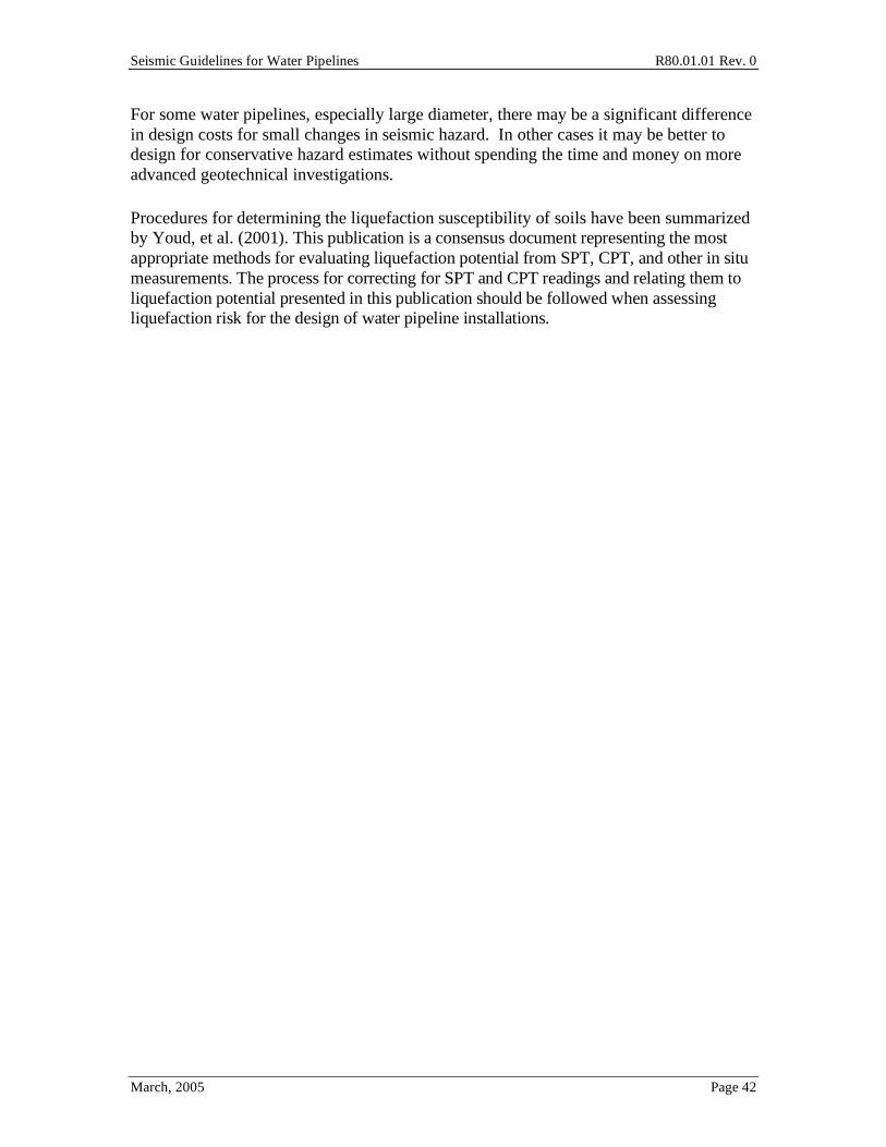
Seismic Guidelines for Water Pipelines R80.01.01 Rev. 0
March, 2005 Page 42
For some water pipelines, especially large diameter, there may be a significant difference in design costs for small changes in seismic hazard. In other cases it may be better to design for conservative hazard estimates without spending the time and money on more advanced geotechnical investigations.
Procedures for determining the liquefaction susceptibility of soils have been summarized by Youd, et al. (2001). This publication is a consensus document representing the most appropriate methods for evaluating liquefaction potential from SPT, CPT, and other in situ measurements. The process for correcting for SPT and CPT readings and relating them to liquefaction potential presented in this publication should be followed when assessing liquefaction risk for the design of water pipeline installations.

Seismic Guidelines for Water Pipelines R80.01.01 Rev. 0
March, 2005 Page 43
6.0 General Pipeline Design Approach Chapter 6 provides a review of normal load conditions that should be considered in conjunction with design for earthquake loading. Chapter 6 is not meant to be comprehensive, but to highlight some of the usual considerations.
6.1 Internal Pressure The internal pressure used in the design of a water pipe system should be the larger of:
o The maximum operating pressure. This should consider hydrostatic (no flow) pressure, operating pressure, failure of control devices, operator error and anticipated over-pressure transients such as water hammer.
o Any in service pressure leak test.
Design allowable stresses for internal pressure are given in applicable AWWA documents.
6.2 Vertical Earth Load Under most operating conditions with soil cover of 3 to 4 feet, the vertical earthquake load for buried water pipes can be neglected since it is insignificant compared to the internal pipe pressure. Vertical earth load is an important consideration for the design of pipe casings used for rail and road crossings due to the heavy loads involved.
Welded steel water pipe is considered flexible. For flexible pipes placed in a trench and covered with backfill, the earth dead load applied to the pipe is the weight of a prism of soil with a width equal to the pipe and a height equal to the depth of fill over the pipe.
Figure 6-1. Soil Prism Above Flexible Pipe
For the case when the water table is below the top of the pipe, the upper bound estimate of load acting on the pipe from earth dead load is:

Seismic Guidelines for Water Pipelines R80.01.01 Rev. 0
March, 2005 Page 44
Pv = dC [Eq 6-1]
For conditions with the pipe located below the water table, the effect of soil grain buoyancy can be approximated by:
Pv = whw + Rw dC
d = dry unit weight of backfill
Rw = water bouyancy factor = 1 0.33 hwC
[Eq 6-2]
Alternately, the vertical dead load can be conservatively estimated from [Eq 6-1] assuming saturated soil conditions.
The effect of soil dead weight and resulting pipe ovality should be considered when establishing ring buckling (wrinkling) capacity of the pipe.
6.3 Surface Live Load Buried pipes can be exposed to superimposed concentrated or distributed live loads, including truck-wheel loads, railway car, locomotive, aircraft loads, etc.
Depending on the requirements of the design specification, the live-load effect may be based on AASHTO HS-20 truck loads, Cooper E-80 railroad loads or a 180 kip airplane gear assembly load, as listed in Table 6-1. These values include an impact factor of 1.5 to account for bumps and irregularities in the travel surface. H20 loads become negligible for cover over 8 feet. E-80 loads become negligible for cover of 30 feet. Airport loads become negligible for cover of 24 feet.
Height of Cover Live Load transferred to the pipe, psi Feet Highway H20,
Note 1 Railway E80
Note 2 Airport Note 3
1 12.50 2 5.56 26.39 13.14 3 4.17 23.61 12.28 4 2.78 18.40 11.27 5 1.74 16.67 10.09 6 1.39 15.63 8.79 7 1.22 12.15 7.85 8 0.69 11.11 6.93
10 - 7.64 6.09 12 - 5.56 4.76
Table 6-1. Live Loads

Seismic Guidelines for Water Pipelines R80.01.01 Rev. 0
March, 2005 Page 45
Note 1. Simulates 20 -ton truck traffic, with impact Note 2. Simulates 80,000 lb/ft railway load, with impact Note 3. 180,000 pound dual-tandem gear assembly, 26 inch spacing between tires and 66 inch center-to-center spacing between fore and aft tires under a rigid pavement 12 inches thick, with impact
For live loads other than those in Table 6-1, the pressure Pp applied to the buried pipe by
a concentrated surface load Ps , without impact, is:
Pp =Ps
2 C2 1+d
C
2
2.5 [Eq 6-3]
where Pp is the pressure transmitted to the pipe, Ps is the concentrated load at the
surface, C is the height of cover, d is the offset distance from the pipe centerline to the line of application of the surface load.
The pressure Pp should be multiplied by the impact factors in Table 6-2.
Height of Cover Installation Surface Condition Feet Highway H20,
Note 1 Railway E80
Note 2 Runways Note 3
0 to 1 1.50 1.75 1.00 1 to 2 1.35 1.50 1.00 2 to 3 1.15 1.50 1.00
Over 3 1.00 1.35 1.00
Table 6-2. Impact Factors
For checking the pipeline, both empty condition and pressurized condition should be checked. In the pressurized condition, the external down pressure can be reduced by the internal pipe pressure.
When a surcharge load is distributed over the ground surface area near a pipeline, the possibility exists that the external surcharge may cause lateral or vertical displacement of the soil surrounding the pipeline. In this case, additional information, including a suitable geotechnical investigation, may be needed to determine if the pipeline could be subjected to soil displacement. A detailed investigation is in order if the distributed surcharge load over an area larger than 10 square feet exceeds the values below (weight of material placed of height of soil fill added over the pipeline):
o 1,500 psf or 15 feet of fill - nominal pipe diameter 12 inches or less

Seismic Guidelines for Water Pipelines R80.01.01 Rev. 0
March, 2005 Page 46
o 1,000 psf or 10 feet of fill - nominal pipe diameter over 12 inches
o 500 psf or 5 feet of fill - pre-1941 pipes
6.4 Pipe Ovalization A flexible buried pipe will tend to ovalize under the effect of earth dead and live load (Eq 6-4, modified Iowa deflection). Pipe ovalization due to internal pipe loads (caused by fault offset or PGDs) is not covered in Section 6.4.
y
D=
DlKP
EI( )eq
R3
+ 0.061E '
[Eq 6-4]
where D = pipe diameter (inches), y is the vertical pipe deflection (inches), Dl is the deflection lag factor (~1.0 to 1.5), K is the bedding constant (~0.1), P is the pressure on the pipe due to soil load Pv and live load Pp, psi, R is pipe radius (inches), EI( )eq
is the
pipe wall stiffness per inch of length, in-lb; E' is the modulus of soil reaction, psi.
Figure 6-2. Ovality of Pipe Cross Section, y per Eq 6-4
The pipe wall stiffness is the sum of the pipe wall, lining and coating:
EI( )eq= EI + EliningIlining + EcoatingIcoating
and I =t
12
3
where t = pipe wall thickness, lining thickness or coating thickness.
The modulus of soil reaction E' is a measure of stiffness of the embedment material, which surrounds the pipe. E' is actually a hybrid modulus being the product of the modulus of passive resistance of the soil and the radius of the pipe. Values of E’ vary from close to zero for dumped loose fine grained soil to 3000 psi for highly compacted coarse grained soil. Recent studies show that the confined compression modulus can be used in place of E'.

Seismic Guidelines for Water Pipelines R80.01.01 Rev. 0
March, 2005 Page 47
The imposed loads lead to ring deflection and pipe wall bending stress both with capacity limits. Typical allowable deflections, or cross section ovality, to prevent damage to various lining and coating systems are:
o Mortar lined and coated. 0.02D
o Mortar-lined and flexible coated. 0.03D
o Flexible lined and coated. 0.05D
Through-wall bending in the pipe due to ovality can be estimated as follows:
bw = 4Ey
D
t
D
[Eq 6-5]
where bw is the through-wall bending stress, y /D per equation 6-4, t is wall thickness and D is pipe diameter.
The depth of burial of the pipe coupled with selection of the pipe wall t should be such that the pressure P on the pipe due to earth and surface load is less than the load needed to crush the pipe side wall. For buried pressurized water pipes with D/t ratios of 100 or less, and a yield stress larger than 30,000 psi, crushing of the sidewall is quite unlikely for normal installations.
If the soil and surface loads are too high, the pipe cross section could buckle (Figure 6-3).
Figure 6-3. Ring Buckling of Pipe Cross Section
Equation 6-6 can be used to determine the external buckling load for typical flexible pipe installations:
qa <1
FS32RwB' E '
EI
D3 [Eq 6-6]

Seismic Guidelines for Water Pipelines R80.01.01 Rev. 0
March, 2005 Page 48
where qa is the allowable buckling pressure (psi); FS is the factor of safety (2.5 for (C/D 2; 3.0 for C/D<2); C is depth of coil cover above pipe (inch); D is diameter of pipe (inch); Rw is the water buoyancy factor (Eq 6-2), B' is an empirical coefficient of elastic support (dimensionless) from Eq 6-7 (AWWA M11). For steel pipes, buckling typically takes place when the ovality reaches about 20%.
B'=1
1+ 4e0.065C
D
6.5 Fatigue Under normal operating loads with pipes buried with at least 3 feet of cover, fatigue is not usually considered a problem. Where pipes cross under highways or railroads, and could be subject to repeated high loading, a deeper minimum burial depth will usually be provided (4 feet under highways, 6 feet under railroads).
6.6 Fluid Transients Rapid changes in flow rates in water will cause pressure transients, which in turn generate pressure pulses and transient forces in the piping system. Only the simplest cases can be calculated by hand, for example, the rapid closure of a valve in a pipe. A valve closure is considered rapid if its closing time is
tc
2Lv
cL
[Eq 6-7]
where tc is the closing time, sec; Lv is the length from the valve to an open water source such as a tank, feet; cL is the wave velocity, feet/sec.
cL =12
W
g
1k
+d
Et
[Eq 6-8]
where k is the bulk modulus of compressibility of water (psi), W is fluid weight (lb/ft3), g is the acceleration of gravity (32.2 ft/sec2), d is the inside diameter of the pipe (inch); E is pipe modulus of elasticity for the pipe wall (psi), t is the pipe wall thickness (inch). For steel pipe, this reduces to:
cL =4660
1+1
100d
t
[Eq 6-9]

Seismic Guidelines for Water Pipelines R80.01.01 Rev. 0
March, 2005 Page 49
for k = 300,000 psi and E = 30,000,000 psi. For cast iron pipe, E ranges from 10,000,000 to 15,000,000 psi. For asbestos cement, E is about 3,400,000 psi.
The pressure rise is
P =cLW v( )
144g [Eq 6-10]
where P is the rise in water pressure due to rapid valve closure, psi; W is water weight, lb/ft3; v is the change in liquid velocity from initial flow rate to zero (valve closure case), feet/sec; g is the acceleration of gravity, 32.2 feet/sec2.
The pressure rise will first occur at the closed valve, propagate and reflect from the pressure source (tank). For more complex situations, a fluid dynamics analysis may be required.
The thrust loads due to fluid transients can cause large displacements in above ground pipes. Water hammer loads have often been seen to break supports off pipes (more common); or could rupture the pipe pressure boundary (less common). Thrust forces can readily open up buried segmented pipe joints if the pipe is not adequately restrained through external skin friction with the soil, by concrete anchor blocks, or by restrained couplings across joints. The unbalanced thrust force at a bend can be estimated from:
F = DLF( ) PA [Eq 6-11]
where A is the pipe cross sectional area, and the DLF=2 reflects an assumed dynamic
load factor for fast loading on slow-to-respond above ground pipe or DLF=1 for buried pipe.

Seismic Guidelines for Water Pipelines R80.01.01 Rev. 0
March, 2005 Page 50
7.0 Analytical Models 7.1 Three Models, and When to Use Them This report provides the user three types of analytical models that can be used in the design of buried pipelines. These models are:
• Chart method (Section 7.2). The simplest approach. Avoids all mathematical models, and allows the designer to pick a style of pipe installation based on parameters such as regional maps for PGA and PGD hazards, and the relative importance of the pipeline in the context of the entire water system.
• Equivalent static method (Section 7.3). Uses simple quantifiable models to predict the amount of force, strain and displacement on a pipe for a particular level of earthquake loading. The pipeline can then be designed to meet these quantified values, or pipe styles can be selected that presumably meet these quantified values without a formal capacity to demand check. Pipe selection is usually made by specification from available manufacturer's catalogs.
• Finite element method (Section 7.4). This method uses finite element models to examine the distribution of loading (whether PGA, PGV or most often PGD) over the length of the pipeline, and then uses beam on inelastic foundation finite element models (or sometimes use 2D or 3D mesh models) to examine the state of stress, strain and displacement within the pipeline and pipeline joints.
7.2 Chart Method The Chart Method combines the pipe function classification with the level of seismic hazard to indicate a style of pipeline design.
Figure 2-1 lists the basic steps in the Chart Method:
• Step 1. Get the geographic location of the pipeline.
• Steps 2 and 3. Select the Function Class (I, II, III or IV) factor for the pipeline Section 3 describes how to define the Function Class.
• Steps 4 to 7. Get the level of seismic hazard (PGV, PGD). Section 4 describes how to define the seismic hazard.
• Step 8. Pick a category of pipeline construction (A, B, C, D, E). Use Tables 7-1 through 7-10.
• Step 9. Pick the actual style of construction. Use Tables 7-11 to 7-19.
• Steps 10 and 11. Review Sections 8 through 12 for examples of construction styles to guide design.
• Step 12. Prepare the plans, profiles and specifications for the actual design. These Guidelines do not provide Step 12.

Seismic Guidelines for Water Pipelines R80.01.01 Rev. 0
March, 2005 Page 51
7.2.1 Transmission Pipelines
Transmission pipelines may carry raw or treated water. Transmission pipelines are typically assigned Function Class II, III or IV; the exception would be to use Function Class I for those pipes whose failure would not impact any customers for 30 days or more.
Use Tables 7-1 through 7-4 to set the pipeline design category (A, B, C, D or E). For Function Class I, the pipeline design category is always A. If a portion of a pipeline has two or more categories for the various hazards (ground shaking, transverse PGDs, parallel PGDs, fault offset PGDs), then the highest category controls for that portion of the pipeline. Design categories for sub-transmission pipelines may also be set using Tables 7-1 to 7-4.
Inch/sec Function II Function III Function IV 0 < PGV 10 A A A
10 < PGV 20 A A B 20 < PGV 30 A B C
30 < PGV B C D
Table 7-1. Transmission Pipelines – Ground Shaking
Inches Function II Function III Function IV 0 < PGD 2 A A A – welded steel
B - segmented 2 < PGD 6 A A B
6 < PGD 12 A B C 12 < PGD B C D
Table 7-2. Transmission Pipelines – Liquefaction (Settlement of Lateral Spread) and Landslide Perpendicular to Pipeline Alignment (Transverse Loading)
Inches Function II Function III Function IV 0 < PGD 2 A B B 2 < PGD 6 B B C
6 < PGD 12 C C D 12 < PGD D D E
Table 7-3. Transmission Pipelines – Liquefaction (Lateral Spread) and Landslide Parallel to Axis of Pipeline (Longitudinal Loading)
Inches Function II Function III Function IV 0 < PGD 2 A B B 2 < PGD 6 B B C
6 < PGD 12 C C D 12 < PGD 24 D D E
24 < PGD D E E
Table 7-4. Transmission Pipelines – Fault Offset

Seismic Guidelines for Water Pipelines R80.01.01 Rev. 0
March, 2005 Page 52
7.2.2 Distribution Pipelines
Distribution pipelines are typically in networks. Failure of a single distribution pipeline will not fail the entire network (once that pipe is valved out), but the customers on that failed distribution pipeline will have no water service until the pipe is repaired. In most cases, the engineer can assume that distribution pipelines are "redundant", except in the following cases:
• The pipeline is the only pipe between lower elevation pump station and upper elevation pump station / reservoir in a pressure zone, and that failure of that pipeline will lead to complete loss of supply to the pump station serving a higher zone, or loss of the water in the reservoir for fire fighting purposes. For example, a 12" diameter pipe from lower elevation pump station that delivers water to a higher elevation tank within a pressure zone, and that also serves water to higher elevation pump stations.
• The pipeline is the only pipe delivering water to particularly important customers, such as critical care hospitals. For example, an 8-inch diameter pipe that has a service connection to a 200 bed hospital.
It has been the experience in past earthquakes that there can be a great quantity of damage to distribution pipelines, especially in areas prone to PGDs. While no single distribution pipeline, will in general, be as important as a transmission pipeline, the large quantity of damage can lead to rapid system-wide depressurization, loss of fire fighting capability, and long outage times due to the great amount of repair work needed. Accordingly, it is recommended that most distribution pipes be classified as Function II and very few as Function I (under ~5% of total pipeline inventory). A few distribution pipes serving essential facilities could be classified as Function III or IV; or they could be designated in suitable emergency response plans as prioritized for rapid repair (generally under one day or two days at most).
Inch/sec Function I Function II Function III, IV 0 < PGV 10 A A A
10 < PGV 20 A A A 20 < PGV 30 A A A (with additional
valves) 30 < PGV A A (with additional
valves) B
Table 7-5. Distribution Pipelines – Ground Shaking

Seismic Guidelines for Water Pipelines R80.01.01 Rev. 0
March, 2005 Page 53
Inches Function I Function II Function III, IV 0 < PGD 2 A A A (with additional
valves) 2 < PGD 6 A A (with additional
valves) B
6 < PGD 12 A B C 12 < PGD A C C
Table 7-6. Distribution Pipelines – Liquefaction (Settlement and Lateral Spread) and Landslide Perpendicular to Pipeline Alignment (Transverse Loading)
Inches Function I Function II Function III, IV
0 < PGD 2 A A B (with additional valves)
2 < PGD 6 A B C 6 < PGD 12 A C D
12 < PGD A D D
Table 7-7. Distribution Pipelines – Liquefaction (Lateral Spread) and Landslide Parallel to Axis of Pipeline (Longitudinal Loading)
Inches Function I Function II Function III, IV
0 < PGD 2 A B B 2 < PGD 6 A B C
6 < PGD 12 A C D 12 < PGD 24 A D E
24 < PGD A E E
Table 7-8. Distribution Pipelines – Fault Offset
7.2.3 Service Laterals and Hydrant Laterals
Inch/sec Any Lateral 0 < PGV 10 A
10 < PGV 30 A 30 < PGV B
Table 7-9. Laterals – Ground Shaking
Table 7-10. Laterals – Liquefaction, Landslide and Surface Faulting
Inches Any Lateral 0 < PGD 2 A
2 < PGD 12 B 12 < PGD C

Seismic Guidelines for Water Pipelines R80.01.01 Rev. 0
March, 2005 Page 54
7.2.4 Design Approach
There are five design categories. Category A denotes standard (non-seismic) design and the others have progressively increasing seismic ruggedness. The following summarizes the general design approach for Categories B, C, D and E:
• B = restrained pipe joints with extra valves • C = same as B plus use of better pipe materials • D = same as C plus quantified seismic design; or provide bypass system per
Section 9. • E = same as D plus peer review (it is strongly recommended that FEM method be
used for any pipe with Category E)
Tables 7-11 through 7-19 provide guidance for design based for each category A through E. This guidance is based on commonly available pipe and joinery as of 2005. As new pipe products become available, they can be used in the chart method as long as suitable justification (FEM, test, etc.) is provided to show that the pipe meets the intended pipe performance goal.
Pipe Category Design Features Notes A Standard B Extended Joints C Restrained Joints D Extended and Restrained Joints
– or use other material Standard with bypass1
E Special Joints Standard with bypass
Table 7-11. Ductile Iron Pipe
Pipe Category Design Features Notes
A Standard B Standard with extra insertion C Restrained Joints D Not recommended Standard with bypass E Not recommended Standard with bypass
Table 7-12. PVC Pipe
1 Instead of using special joinery, standard push on joints can be used in conjunction with a
bypass system such as described in Section 9.2.

Seismic Guidelines for Water Pipelines R80.01.01 Rev. 0
March, 2005 Page 55
Pipe Category Design Features Notes A Single Lap Weld B Single Lap Weld Weld dimension t = pipe t1 C Double Lap Weld Weld dimension t = pipe t D Double Lap Weld / Butt Weld D/t max 110 in PGD zones2 E Butt Weld D/t max 95 in PGD zones
Table 7-13. Welded Steel Pipe
Pipe Category Design Features Notes
A Standard B Extended Joints Avoid in high PGD zones3 C Extended Joints Avoid in high PGD zones D Extended and Restrained Joints
– or use other design Standard with bypass
E Not recommended Standard with bypass
Table 7-14. Gasketed Steel Pipe
Pipe Category Design Features Notes
A Gasketed or Single Lap weld B Single Lap Weld Weld dimension t = cylinder t4 C Double Lap Weld Weld dimension t = cylinder t D Not recommended Standard with bypass E Not recommended Standard with bypass
Table 7-15. CCP & RCCP Pipe
Pipe Category Design Features Notes
A Standard B Butt Fusion Joints C Butt Fusion Joints D Butt Fusion Joints E Butt Fusion Joints
Table 7-16. HDPE Pipe
1 The weld thickness t should equal the pipe wall thickness t 2 The ratio of pipe diameter D to pipe wall thickness t should be limited to the maximum listed 3 Each extended joints must be able to accommodate the entire PGD. For PGDs much higher than
a few inches, it is not likely that extended joints are practical. 4 The weld thickness t should equal the steel cylinder wall thickness t

Seismic Guidelines for Water Pipelines R80.01.01 Rev. 0
March, 2005 Page 56
Pipe Category Design Features Notes A Standard B Soldered joints C Soldered joints Expansion loop / Christie box /
Other box
Table 7-17. Copper Pipe
Pipe Category Design Features Notes
A Standard B Dresser-type coupling C Multiple dresser couplings D EBAA flextend type couplings E Do not use - relocate
Table 7-18. Segmented Pipelines Used as Hydrant Laterals
Pipe Category Design Features Notes
A Bolted, Single Lap Weld, Fusion Weld
B Bolted, Single Lap Weld, Fusion Weld
Weld t = pipe t
C Bolted, Double Lap Weld, Single Lap Weld with fiber
wrap, Fusion Weld
Weld t = pipe t
D Bolted, Double Lap Weld, Single Lap Weld with fiber
wrap1, Butt Weld, Fusion Weld
E Bolted, Double Lap Weld, Single Lap Weld with fiber
wrap, Butt Weld, Fusion Weld
Table 7-19. Continuous Pipelines Used as Hydrant Laterals
In addition to the pipe design styles in Tables 7-11 through 7-19, the following additional requirements are made. These recommendations are cumulative (For C, include B and C recommendations).
• B. Add isolation valves on all pipes within 50 feet of every intersection, for example, four valves on a four-way cross.
• C. Maximum pipe length between connections for segmented pipe is 16 feet, or as otherwise justified by ESM or FEM.
1 Experimental tests have shown that a single lap welded pipe with external epoxy-attached fiber
wrap have essentially the same capacity as butt welded pipe.

Seismic Guidelines for Water Pipelines R80.01.01 Rev. 0
March, 2005 Page 57
• D. Maximum pipe length between connections for segmented pipe is 12 feet, or as otherwise justified by ESM or FEM.
7.3 Equivalent Static Method The Equivalent Static Method (ESM) computes pipe seismic response quantities (forces, displacements, strains) using idealized models describing the interaction of the hazard, soil and pipe. The purpose is to account for the physical aspects governing the pipe behavior in a simplified manner so the designer can apply the method to specific situations with the understanding of the key mechanisms influencing behavior.
The ESM methodology can be refined using techniques discussed in the commentary and/or using the Finite Element Method. Considering the importance of the pipeline, variability and uncertainty in the hazard description as well as the soil conditions, the capability of the pipeline, and the adverse impacts of limited damage, such refinement may not be warranted or cost effective.
In the ESM, the ground motions might be estimated using regional maps. Then, using simplified models, the ground motions are applied to the pipeline to compute forces or in the pipe body and displacements at the pipe joints. The final pipeline design requires the forces and displacements are less than allowable values.
The ESM makes a number of simplifying assumptions, and it should be understood that the ESM sometimes cannot completely account for unusual ground motions or pipeline configurations. The ESM assumes that pipe manufacturers have or will determine certain capacities (like joint movements) and are willing to make such data available to designers. As of 2005, such information is not widely available in vendor catalogs. However, it is the hope that over time, various pipe manufacturers will provide products with the desired earthquake performance using catalog-type product selection.
The ESM can be used for calculation of pipe response resulting from:
• Ground shaking hazard that produces transient ground strains from seismic wave passage (Section 4.2), and
• Ground failure hazards such as landslides, liquefaction, or surface faulting that result in permanent ground deformations (Sections 4.3, 4.4, 4.5).
7.3.1 Analysis for Ground Shaking Hazard
Ground shaking causes transient ground strains from seismic wave passage that is categorized according to peak ground velocity (PGV). These cause transient strains in buried pipe as it deforms with the soil. The buried pipe moves with the soil at locations subject only to ground shaking without ground failures such as liquefaction, landslide or fault offset. Peak strain in the soil may be estimated as follows:

Seismic Guidelines for Water Pipelines R80.01.01 Rev. 0
March, 2005 Page 58
c
PGV
soil= [Eq 7-1]
where, PGV = peak ground velocity at pipe location as computed per Section 4.2, and c = seismic wave propagation speed in the soil at the pipe location. The wave propagation speed may be taken as 13,000 feet per second unless otherwise justified.
Continuous Pipe
A continuous pipe has joints possessing significant strength and stiffness relative to the pipe barrel (often referred to as restrained joints). An example is a steel pipe having welded (single lap, double lap or butt welded) joints.
The force for designing the pipe barrel and joints may be taken as the smaller of F1 or F2 where F1 is the force assuming the pipe is fully compliant with the soil (ie., the pipe does not slip through the soil), and F2 is the ultimate force the soil can transfer to the pipe.
Assume that the ground strain is transferred to the pipe without slip. Then
pipe = soil =PGV
c
F1 = AE pipe [Eq 7-2]
42
ut
F = [Eq 7-3]
where, A = pipe body axial area, E = Youngs modulus of pipe, tu = ultimate frictional force of soil acting on pipe barrel in axial direction (force per unit pipe length) computed per Section 7.4, and = seismic wavelength in soil at pipe location. The wavelength may be taken as 6,500 feet unless otherwise justified. Section C7.3.1 provides an example.
Segmented Pipe
A segmented pipe has joints having low strength and stiffness relative to the pipe barrel (often referred to as unrestrained joints). An example is a ductile iron or PVC pipe having push-on bell-and-spigot gasketed joints. The ground strains are assumed to be transformed into relative axial displacements between pipe segments that must be accommodated in the pipe joints. Should the resulting relative joint displacement be greater than that available in the joint, the pipe segments will separate at the joint in tension, or the segments will bear against each other in compression, possibly leading to telescoping inside of one another, or local buckling (wrinkling) of the pipe barrel. The axial displacement (in both the axial shortening and lengthening directions) that the joint must be able to accommodate may be taken as follows.

Seismic Guidelines for Water Pipelines R80.01.01 Rev. 0
March, 2005 Page 59
joint = 7Lp soil [Eq 7-4]
where, Lp = length of the pipe segment.
Laboratory tests show that the axial stiffness and strength vary from joint to joint. As a result the weak joints are subject to larger relative joint displacements than their stronger neighbor. El Hamadi and O'Rourke (1990) have shown that for cast iron pipe with lead caulked joints about one in a hundred joints (1% of joints) are subject to three times the average joint displacement while one in a thousand (0.1%) are subject to five times the average. For design purposes, the Guidelines recommend the use of seven times the average joint movement, and this would be expected to result in damage in no more than 1 in 10,000 joints. For example, assuming a PGV of 50 cm/sec and pipe segment length of 16 feet, then:
joint = 7Lp
PGV
c= 7*16*12
50
13,000x12x2.54= 0.17 inches [Eq 7-5]
Note that the joint displacement is relatively small.
Continuous Pipe - Design Considerations
If using a single lap welded pipe, the stress in the joint will be amplified over the stress in the main body of the pipe. This is caused by several reasons: the geometry of the joint will introduce net bending, which will increase the maximum longitudinal stress; the stress within the lap weld will include the factors of longitudinal axial, bending and hoop forces; the thickness of the weld; and possibly stress concentrations at within and near the weld due to weld flaws. In the ESM method, we make the overly simplified assumption that most single lap welded joints (outside welds) with minimum leg size equal to the minimum pipe wall thickness can sustain some localized yielding before leading to failure, so we suggest the following acceptance criteria.
pipe 0.40Fy [Eq 7-6]
where Fy = nominal specified yield stress of the pipe. This formula implies a joint efficiency of about 35% as compared to the strength of the pipe. For cases where a single lap welded pipe is used with thinner welds, then use:
pipe
t
tweld
0.40Fy [Eq 7-7]
Single lap welded steel pipes exhibit about the same strength in tension or compression. Once the axial load reach about ±0.60 Fy in the main body of the pipe, strains within the single lap weld will reach about 5% to 6% under compressive loading or 8% to 9% under tension loading. The design longitudinal stress allowable for a single lap welded pipe

Seismic Guidelines for Water Pipelines R80.01.01 Rev. 0
March, 2005 Page 60
(external lap weld equal to wall thickness) should not exceed about 0.60Fy in the main pipe, under maximum earthquake.
For double lap welded steel pipe with common fit up tolerances, replace 0.40 with 0.90 for tensile loading. Due to eccentricities in a double lap welded pipe at the connection, predicted tensile stresses of 0.90Fy in the main body of the pipe away from the joint will translate to about 3% strain or so within the highest strained part of the lap welded joint. Initial yielding of the double lap welded joint will occur at about 50% to 60% Fy in the main pipe. In the highly nonlinear realm, predicted tensile longitudinal strains of about 5% in the main body of the pipe will translate to about 10% strain in the highest strained part of the welded lap joint.
In compression, a double lap welded steel pipe with common dimension tolerances (D/t = 175) will buckle at a compressive load of about 0.60Fy. The pipe will continue to shorten in its buckled shape as compressive loading is maintained, albeit with load shedding and with increasing strain in the pipe. By the time the wrinkle has formed to cause about 1 inch bulging in or out, the peak strain in the male or female parts of the spigot joint will reach about 13 to 14% strain (unpressurized) or about 12% to 15% strain (pressurized to 150 psi).
For butt welded pipe, replace 0.90 with 1.00; or use nonlinear strain acceptance criteria.
If the designer opts for some nonlinear performance of the pipe, the stress checks should be replaced with tensile strain limit checks and wrinkling checks. Single lap welded pipe should generally be limited to the above elastic limits. Double lap welded or butt welded pipe can accept some strain or wrinkling, with butt welded pipe performing better than double lap welded pipe. For water pipes, some wrinkling is acceptable if the owner accepts this performance, and if pipe failure does not lead to serious impacts to nearby pipes, structures or habitat.
For pipes connected using bolted flanged joints, then the above equations are used, with the weld being that between the flange and the pipe. It is assumed that the flange and bolts will be sized based on pressure requirements, and that seismic loading from ground shaking will not control.

Seismic Guidelines for Water Pipelines R80.01.01 Rev. 0
March, 2005 Page 61
Segmented Pipe - Design Considerations
The predicted movement of the pipe joint should be less than the movement capacity of the pipe joint. The predicted joint movement is both for tension (pull out) and compression (push in) of the joint. Depending of the style of pipe hardware used, the joint might allow tension and compression movements with similar resistance (common for PVC-style joints) or dissimilar resistance (common for cast iron and ductile iron joints). From observation in past earthquakes, compression failures of ductile iron pipes are rare, so this is not a significant concern. Thus, the larger concern is that the pull out movement should not exceed the capacity of the joint.
The required joint movement (in tension) should be capable of resisting the predicted seismic joint movement as follows:
joint seismic
where joint is the capacity against joint pull out at the time of the earthquake,
considering any simultaneous operational forces (temperature, static thrust, hydrodynamic thrust, etc.) and in consideration of construction fit-up tolerances. Without causing too much damage to an overall pipe network, joint pullout failures on the order of one per 6,000 should be tolerable. For pipelines constructed with good quality control, and with the spigot end of essentially every joint is installed to the full depth required, then:
design = seismic + operational
To provide for some measure of safety, a margin might be included in the design as follows:
design = seismic + operational + 0.25 inch [Eq 7-8]
Where the 0.25 inch value accommodates the likely range of fit-up tolerances in construction to cover the vast majority of the installations. For cast iron pipe, the previous example suggests that using 7 times the average joint opening movement might be used rather than the average movement plus 0.25 inches. Either design approach seems reasonable.
Concurrent with the joint displacement requirement, segmented pipe joints will be required to take some joint rotation under seismic loads. For these Guidelines in the ESM approach, we do not provide a specific rotation capability numerical check, as it is felt that any rubber gasketed joint capable of providing the axial displacement requirement will also provide adequate joint rotation. However, for installations designed to take PGDs of a few inches or more over one pipe segment length, joint rotations will be important, and the above approach is not suitable.

Seismic Guidelines for Water Pipelines R80.01.01 Rev. 0
March, 2005 Page 62
Continuous Pipeline with One Unrestrained Joint
A common situation arises when an expansion coupling is inserted into long continuous steel pipeline. For example, the expansion coupling may be useful to allow for removal of a valve in a welded steel pipeline. As another example, consider the case of a reinforced concrete cylinder pipe with gasketed and cemented joints, when just one of the joints is cracked.
For this case, the joint opening (or closing) movement can be calculated using the following approach, which is described in ASCE (1984) and quantified by O'Rourke, Wand and Shi (2004).
Assume that the ground strain g acts over a pipeline with axial area A, Young's modulus E, axial skin friction tu (defined in Section 7.4), wavelength (Figure 7-1).
Figure 7-1. Sinusoidal Wave Interaction with Pipe
Assume that at the expansion joint (or single cracked joint) that the strain in the pipe p is
zero. The maximum accumulation of strain in the pipe away from that joint is limited to that force transferred from the soil to the pipe, tu. At some distance L from the joint, the strain in the pipe will increase to the strain in the ground, beyond which the pipe will move with the ground (assuming no further soil-pipe slippage, which is reasonable under most ground shaking hazard situations). This analogy is shown in Figure 7-2.

Seismic Guidelines for Water Pipelines R80.01.01 Rev. 0
March, 2005 Page 63
Figure 7-2. Relative Joint Displacement at Expansion Joint in Continuous Pipeline
If one can estimate all the parameters in Figure 7-2, then the relative axial joint displacement is just the area between the pipe strain and ground strain curves. If one assumes that the wave length is very long such that the strain in the pipe equals (or nearly equals) the maximum ground strain, then the area under the curve in Figure 7-2 is:
=V
c
2EA
tu
[Eq 7-9]
This will overestimate the true relative joint displacement, in all practical cases. O'Rourke, Wang and Shi (2004) ran a series of finite element analyses for pipes with varying E and A, soil conditions tu and seismic wave characteristics ( , c, T= c , where
T = dominant wave period). The results are summarized in Figure 7-3.
Figure 7-3. Relationship Between 0 and tu
EAR

Seismic Guidelines for Water Pipelines R80.01.01 Rev. 0
March, 2005 Page 64
7.3.2 Landslide and Liquefaction Permanent Ground Deformations
Earthquakes can trigger landslides and soil liquefaction that are the mass movement of soil over an extended area. These can be very damaging to buried pipes as they are dragged along within the soil mass and experience applied relative deformations. The pipe response depends on its orientation relative to the direction of the soil mass permanent ground displacement (PGD), as highlighted in Figure 7-4.
• A pipe run oriented parallel to the soil movement is defined as experiencing longitudinal PGD.
• A pipe run oriented perpendicular to the soil movement is defined as experiencing transverse PGD.
• We do not provide ESM formula for intermediate cases, but a vector addition of the two cases could be applied should a pipe be exposed to some movement in both the longitudinal and transverse directions. The FEM method can treat any orientation.
In general, longitudinal PGD are more damaging than transverse PGD. Empirical observations suggests that damage rates for non-seismically designed pipes for longitudinal PGDs have been 5 to 10 times higher than corresponding damage rates due to transverse PGDs. This is in part due to the fact that a pipe is inherently more flexible or compliant when subject to bending (transverse PGD) then when subject to axial tension or compression (longitudinal PGD).
In the ESM method, highly simplified and semi-empirical methods are provided to treat permanent ground deformations. These approaches can be used for pipes that traverse through liquefaction zones. For especially important pipes that are subject to large PGDs (over a foot or so) (like landslides or surface fault offset), the more detailed FEM is recommended.

Seismic Guidelines for Water Pipelines R80.01.01 Rev. 0
March, 2005 Page 65
Figure 7-4. Principal effects of PGDs on pipelines according to their orientation
The direction of PGD for landslides is assumed to be down-slope. The direction of PGD due to liquefaction lateral spreading may be assumed as follows:
• Locations 1,000 feet from of a water boundary (such as a stream, lake, or ocean front that constitutes a “free-face”) will have PGD directed toward the free-face.
• Locations > 1,000 feet from a water boundary having an average slope > 1% will have PGD directed down-slope.
• Locations not meeting above may have PGD oriented in any direction.
Buried Pipe Response to Longitudinal PGD
The maximum pipe forces and displacements generally occur at the margins of the soil mass undergoing movement causing either pipe tension (pull-out at the head of the moving soil mass, point A in Figure 7-5), or pipe compression (push-in at the toe of the moving soil mass, point B in Figure 7-5). Design for longitudinal PGD will generally be controlling.

Seismic Guidelines for Water Pipelines R80.01.01 Rev. 0
March, 2005 Page 66
Figure 7-5. Pipe Response to Longitudinal PGD
Continuous pipe. The force for designing the pipe barrel and joints may be taken as the smaller of F1 or F2 representing upper bound estimates of the axial force in the pipe. F1 is the force assuming the pipe is elastic and fully compliant with the soil, and F2 is the ultimate force the soil can transfer to the pipe.
F1 = AEtu [Eq 7-10]
where, = PGD displacement estimated from Sections 4.3 and 4.4. In lieu of specific knowledge about the particular site, e.g., via geotechnical studies, the commentary contains suggested values for .
22
suLt
F = [Eq 7-11]
where, Ls = length of pipe in soil mass undergoing movement estimated from Section 4.3 and 4.4. In lieu of specific knowledge about the particular site, e.g., via geotechnical studies, the commentary provides suggested values for Ls. F2 assumes that half the total

Seismic Guidelines for Water Pipelines R80.01.01 Rev. 0
March, 2005 Page 67
applied soil load is resisted in tension and half in compression; for pipes with bends, up to the entire applied soil load may be imposed on the pipe.
In situations where elastic design using the computed force above is not practical (requiring pipe and joints to have excessive strength), plastic design is recommended. For plastic design, the pipe should consist of ductile material capable of large plastic strains without fracture, and the joints should be capable of developing the strength of the adjoining pipe segments (e.g., steel pipe having welded joints).
For Function Class III or IV continuous pipe with bends in or near the PGD zone, the FEM method is suggested; equations 7-10 and 7-11 do not account for bends.
Segmented pipe. The ground displacement is assumed to be accommodated by pipe joint expansion and contraction. The axial displacement that the joint must be able to accommodate may be taken as follows.
For push-on type pipe joints (not having mechanical stops preventing pipe segments from pulling apart), the design displacement may be taken as:
joint =
For pipe joints having mechanical stops preventing pipe segments from pulling apart, the PGD may be assumed to be distributed over several joints. We call such joints "chained joints". The design displacement may be taken as:
joint =n
[Eq 7-12]
Where, n = the number of chained restrained joints near the head or near the toe of the moving soil mass that will expand to absorb the total PGD. Figure 7-6 illustrates the definition of n. In Figure 7-6, we illustrate that the sharply imposed PGD is equally taken up by n=3 joints at both the head and toe of the soil mass. This implies that all the joints and all the soil is equally stiff and strong. In reality, it is quite possible that the soil mass on one side of the head or two will be stiffer than on the other side (hence the proclivity for the ground crack at the interface. This might force all n joints to absorb the PGD to be on just one side of the ground crack, not equally distributed as illustrated.
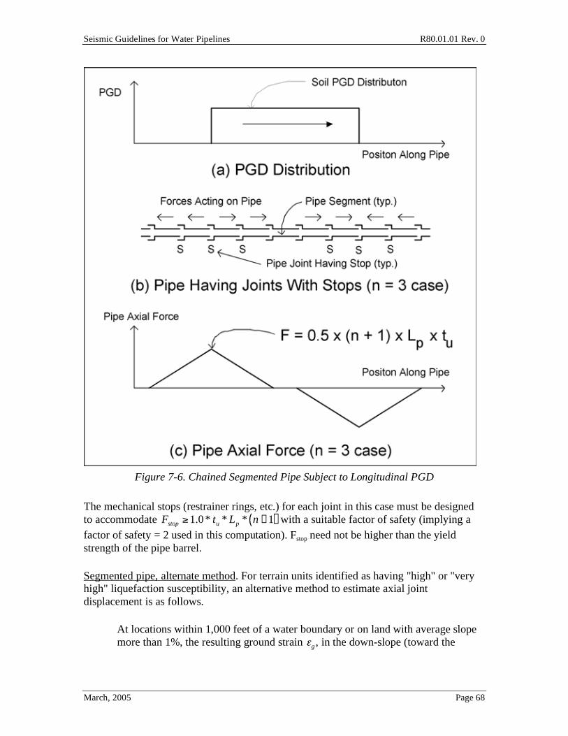
Seismic Guidelines for Water Pipelines R80.01.01 Rev. 0
March, 2005 Page 68
Figure 7-6. Chained Segmented Pipe Subject to Longitudinal PGD
The mechanical stops (restrainer rings, etc.) for each joint in this case must be designed to accommodate Fstop 1.0* tu * Lp * n +1( ) with a suitable factor of safety (implying a
factor of safety = 2 used in this computation). Fstop need not be higher than the yield strength of the pipe barrel.
Segmented pipe, alternate method. For terrain units identified as having "high" or "very high" liquefaction susceptibility, an alternative method to estimate axial joint displacement is as follows.
• At locations within 1,000 feet of a water boundary or on land with average slope more than 1%, the resulting ground strain g , in the down-slope (toward the

Seismic Guidelines for Water Pipelines R80.01.01 Rev. 0
March, 2005 Page 69
water) horizontal direction may be assumed to be 1.5%. The ground strain is assumed to be uniform throughout.
• At locations more than 1,000 feet from of a water boundary or on land with average slope less than 1%, the resulting ground strain g , in any horizontal
direction may be assumed to be 0.75%. The ground strain is assumed to be uniform throughout..
For segmented pipes installed in such liquefaction areas, a chained joint can be designed to accommodate the ground strain as follows, (a chained joint is a segmented joint with the additional requirement of having mechanical stops to prevent the pipes from pulling apart should the amount of PGD require movement at more than one joint). The chained joints are installed throughout the zone subject to PGD, plus at least the first three joints (or for a pipe length needed to provide full anchorage) outside the PGD zone.
joint = gLp [Eq 7-13]
The strength of the chained joint stop should be high enough to accommodate the accumulated pulling load, Fstop 1.0* tu * Lp * n +1( ) . However, in this alternate design
approach, n is not formally computed; one would have to rely upon the manufacturer's catalog item to provide a suitably strong stop, or the designer can work with the manufacturer to establish a suitably strong stop.

Seismic Guidelines for Water Pipelines R80.01.01 Rev. 0
March, 2005 Page 70
Buried Pipe Response to Transverse PGD
The pipe is characterized as taking the displaced shape of a beam under lateral loading with the peak displacement occurring at the middle of the span (i.e. at the center of the soil mass), Figure 7-7. This assumes a distributed PGD across the slide having a maximum displacement near the center and small displacements near the margins of soil mass. (A more severe situation is where the PGD occurs abruptly near the margins of the soil mass analogous to a pipe fault crossing discussed below. However, effectively designing for this situation requires rather specific knowledge about the locations of the soil mass margins so that treating it this way ought to be considered only if there is site-specific geologic hazard information.)
Figure 7-7. Pipe Response to Transverse PGD
Continuous pipe. The peak bending strain in the pipe can occur either at the center or near the margins of the transverse-moving soil mass, points A, B and C in Figure 7-7. These may be conservatively estimated as the smaller of the following.
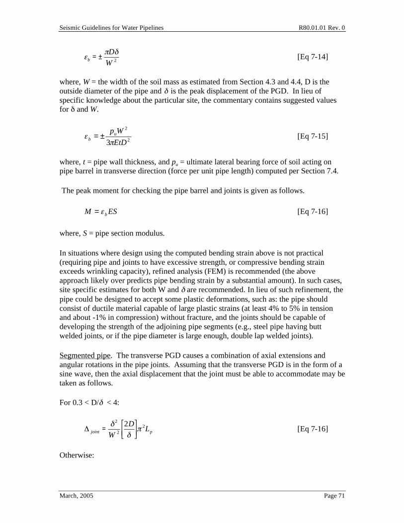
Seismic Guidelines for Water Pipelines R80.01.01 Rev. 0
March, 2005 Page 71
b = ±D
W 2 [Eq 7-14]
where, W = the width of the soil mass as estimated from Section 4.3 and 4.4, D is the outside diameter of the pipe and is the peak displacement of the PGD. In lieu of specific knowledge about the particular site, the commentary contains suggested values for and W.
2
2
3 EtD
Wpu
b±= [Eq 7-15]
where, t = pipe wall thickness, and pu = ultimate lateral bearing force of soil acting on pipe barrel in transverse direction (force per unit pipe length) computed per Section 7.4.
The peak moment for checking the pipe barrel and joints is given as follows.
ESMb
= [Eq 7-16]
where, S = pipe section modulus.
In situations where design using the computed bending strain above is not practical (requiring pipe and joints to have excessive strength, or compressive bending strain exceeds wrinkling capacity), refined analysis (FEM) is recommended (the above approach likely over predicts pipe bending strain by a substantial amount). In such cases, site specific estimates for both W and are recommended. In lieu of such refinement, the pipe could be designed to accept some plastic deformations, such as: the pipe should consist of ductile material capable of large plastic strains (at least 4% to 5% in tension and about -1% in compression) without fracture, and the joints should be capable of developing the strength of the adjoining pipe segments (e.g., steel pipe having butt welded joints, or if the pipe diameter is large enough, double lap welded joints).
Segmented pipe. The transverse PGD causes a combination of axial extensions and angular rotations in the pipe joints. Assuming that the transverse PGD is in the form of a sine wave, then the axial displacement that the joint must be able to accommodate may be taken as follows.
For 0.3 < D/ < 4:
joint =2
W 2
2D
2Lp [Eq 7-16]
Otherwise:
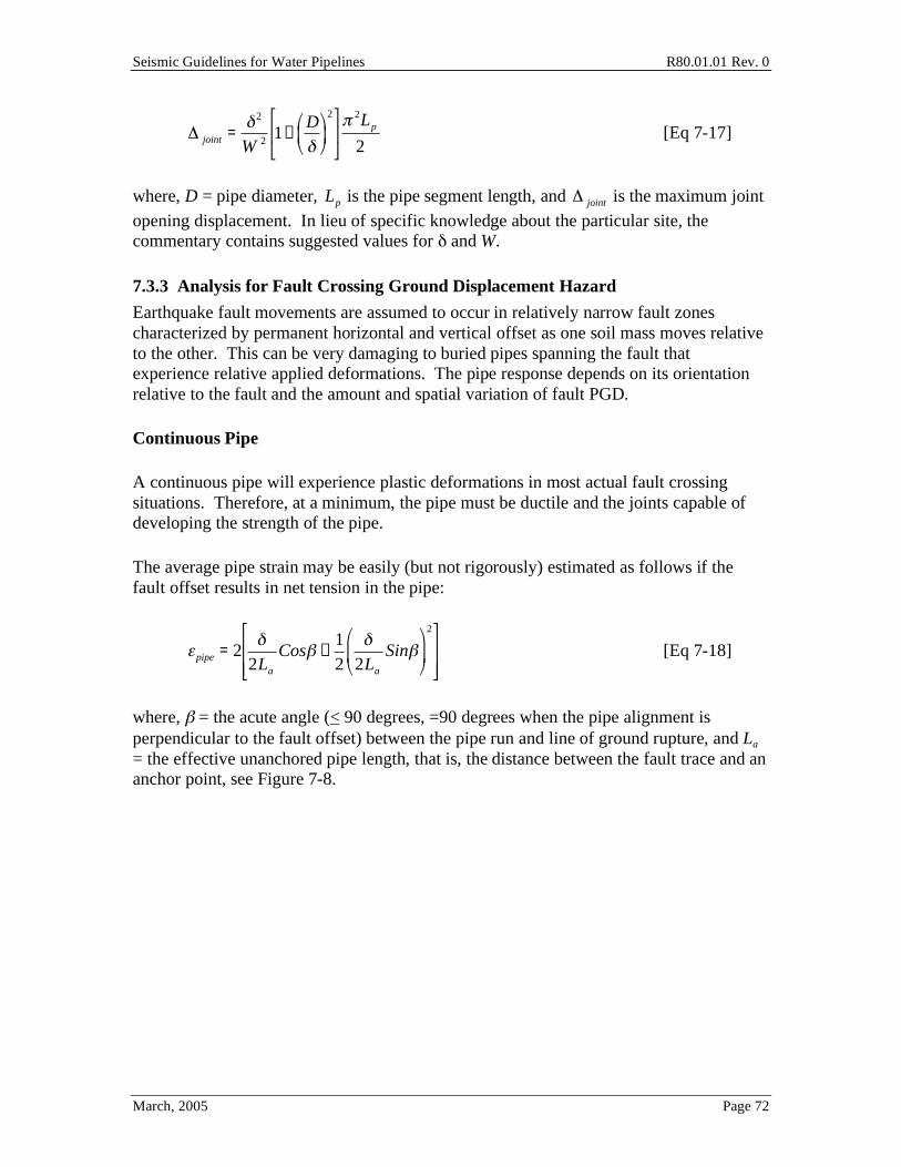
Seismic Guidelines for Water Pipelines R80.01.01 Rev. 0
March, 2005 Page 72
joint =2
W 2 1+D
2
2Lp
2 [Eq 7-17]
where, D = pipe diameter, Lp is the pipe segment length, and joint is the maximum joint
opening displacement. In lieu of specific knowledge about the particular site, the commentary contains suggested values for and W.
7.3.3 Analysis for Fault Crossing Ground Displacement Hazard
Earthquake fault movements are assumed to occur in relatively narrow fault zones characterized by permanent horizontal and vertical offset as one soil mass moves relative to the other. This can be very damaging to buried pipes spanning the fault that experience relative applied deformations. The pipe response depends on its orientation relative to the fault and the amount and spatial variation of fault PGD.
Continuous Pipe
A continuous pipe will experience plastic deformations in most actual fault crossing situations. Therefore, at a minimum, the pipe must be ductile and the joints capable of developing the strength of the pipe.
The average pipe strain may be easily (but not rigorously) estimated as follows if the fault offset results in net tension in the pipe:
pipe = 22La
Cos +1
2 2La
Sin
2
[Eq 7-18]
where, = the acute angle (< 90 degrees, =90 degrees when the pipe alignment is perpendicular to the fault offset) between the pipe run and line of ground rupture, and La = the effective unanchored pipe length, that is, the distance between the fault trace and an anchor point, see Figure 7-8.

Seismic Guidelines for Water Pipelines R80.01.01 Rev. 0
March, 2005 Page 73
Figure 7-8. Plan View of Pipeline Equation [7-18]
When no bends, tie-ins or other constraints are located near the fault, then the axial resistance is provided by the soil-pipe friction and the effective unanchored pipe length may be taken as follows.
La =Py
tu
+P Py
tu
[Eq 7-19]
where, Py = yield strength of pipe in tension and P = actual tensile force in the pipe at the fault crossing (requires iteration). The above is the Newmark-Hall method, but scaled higher by a factor of 2 to reflect unconservatisms in the Newmark-Hall analogy (see commentary). Even with this factor of 2, this model may overestimate pipe capacity to withstand fault offset, and in general should only be used as a first order approximation; FEM methods are recommended to be used for important (Function Class III or IV) pipelines.
In general, plastic design should be used for fault offset loading. Pipe material must be ductile and capable of plastic strains exceeded the computed average pipe strain without fracture. The joints should be capable of developing the strength of the adjoining pipe segments (e.g., steel pipe having double lap welded or butt welded joints may be acceptable, but single lap welded joints or riveted joints are generally not satisfactory to allow for ductile behavior of the pipe).

Seismic Guidelines for Water Pipelines R80.01.01 Rev. 0
March, 2005 Page 74
Segmented Pipe
The fault offset is assumed to be accommodated equally by the pipe joints located immediately on each side of the line of ground rupture (faulting crosses the pipe barrel and not at the joint). In this case, each joint is subjected to an axial displacement and angular rotation that may be calculated as follows.
joint =2
cos [Eq 7-20]
joint = Arc sinLp
sin
[Eq 7-21]
The shear force and moment in the pipe barrel that crosses the line of ground rupture may be calculated as follows (assuming fault crosses at midpoint of pipe segment).
4
puLp
V = [Eq 7-22]
32
2
puLp
M = [Eq 7-23]
where, pu = ultimate lateral bearing force of soil acting on pipe barrel.
7.4 Finite Element Method The Finite Element Method (FEM) can be used for the analysis and design of any pipeline. With the advent of low cost high-powered personal computers, the use of the FEM method can be adopted for many pipeline applications, covering ground shaking, liquefaction, landslide and surface faulting hazards. In practice, it will normally be used for the most important pipelines (Function Class III and IV) subject to PGD.
Figure 7-9 shows the typical form of the FEM. The pipe can be modeled with beam-type (or pressurized pipe) line elements. Near the fault offset, the length of the beam/pipe elements should not be longer than the pipe diameter. The model should accommodate both material and geometry (large deformation) nonlinearities. (In a more generalized case, axisymmetric and shell-type elements could be used to examine special fittings and other factors. However, this latter case is not covered here.) The soil is modeled by lateral and axial springs having the ability to mimic the nonlinear soil force-deformation behaviors. The loading, usually PGD, is modeled by displacements applied to the ends of the soil springs to simulate the soil-pipe interaction.

Seismic Guidelines for Water Pipelines R80.01.01 Rev. 0
March, 2005 Page 75
The normally reported stresses and strains from a beam-type FEM are the longitudinal-direction actions. The user should be cautioned that these stresses and strains are not the same as the stresses and strains in the pipe wall once the wall begins to substantially distort (such as in wrinkling). Distinction as to the allowable strains in a pipe must be made, when such strains are calculated using beam-element or pipe-element type models, or when such strains are calculated with consideration of localized bending, etc. at wrinkled locations. In these Guidelines, unless otherwise noted, all compressive strains are reported as allowable compressive strains in the main body of the pipe near but not in the wrinkle, recognizing that the strain in the wrinkling joint will be higher.
Figure 7-9. Finite Element Model (Beam Type) of Buried Pipeline and Soil Loads and
Restraint

Seismic Guidelines for Water Pipelines R80.01.01 Rev. 0
March, 2005 Page 76
7.4.1 Pipe Modeling Guidelines
For models of the type in Figure 7-9(a), (b), a low pressure water pipe can be reasonably modeled using beam elements (effects of internal pressure ignored) or pipe elements (effects of internal pressure included). The typically reported stresses and strains from such elements are the longitudinal-direction actions. These stresses and strains are not the same as the stresses and strains in the pipe wall once the wall begins to substantially distort (such as when the pipe wall undergoes local buckling, often referred to as “wrinkling”). Hence, the results from such elements must be evaluated with consistent compressive wrinkling and tensile strain limits criteria presented in sections 7.4.3 and 7.4.4.
Depending on the pipeline geometry and loading, the model may need to include three dimensions. Pipe elements should be discretized at relatively short lengths near the transition point where the PGDs occurs (e.g., proximate to the fault). For example, a pipe could be discretized at one-fifth diameter intervals, for ten pipe diameters either side of the imposed PGD. This will generally provide adequate capability to capture the localized peak bending gradient in the pipeline. At locations distant from the imposed PGD transition point, the pipe element lengths could be up to 5 times the pipe diameter, without loss of accuracy.
The material properties of the pipeline should be set to capture the nonlinear capability of the pipe material. Tests of actual steel from water pipelines suggests that the flat yield plateau exhibited by virgin A36 steel might not be present, in part because of the rolling involved in the original pipe manufacture; and for high strain rate applications like many types of seismic loading, the flattened plateau might not be present.
7.4.2 Soil Modeling Guidelines
For cases where there are imposed PGDs on the pipeline (such as at fault crossings, landslide transition points, etc.), it would be expected that the pipe will slip through the soil. Thus, the soil load-deflection curves (Figure 7-9(c)) will need to be nonlinear. The following outlines the usual formulation for soil springs; it is suitable for the engineer to modify these formulations to reflect actual field conditions, whether from test, experience, judgment or analysis.
The following are the soil springs including example values assuming a 42-inch inside diameter butt welded steel pipeline, with wall t = 0.5 inches, in a firm clay type backfill, for application in a fault crossing situation. The inner lining and outer coating in the fault crossing area are assumed to be fusion bonded epoxy. In the formulations below, it is assumed that undrained conditions prevail for clays while drained conditions prevail in sands.

Seismic Guidelines for Water Pipelines R80.01.01 Rev. 0
March, 2005 Page 77
Axial Spring (t-x curve)
tu =
D Su for clay D
2H 1+ Ko( ) tank for sand
[Eq 7-24]
xu =0.1 to 0.2 inches for dense to loose sand
0.2 to 0.4 inches for stiff to soft clay
These soil springs are inferred from pile shaft load transfer theory, where, u
t = maximum
soil resistance to the pipe axial direction having units of force per unit length of pipe,
ux = axial displacement at which maximum soil resistance is developed, D = pipe outer
diameter, = adhesion factor from Figure 7-10, u
S = soil undrained shear strength, =
soil effective unit weight, H = soil depth to centerline of pipe, o
K = coefficient of lateral
soil pressure at rest, = angle of soil shear resistance, k is a factor to represent the friction between the outer surface of the pipe and the surrounding soil (if that is the failure plane), such that ( ktan ) is in the range of about 0.6 to 0.7 for concrete coated steel pipe in compacted sand; or 0.4 to 0.5 for hard epoxy coated steel pipe in compacted sand.
For design purposes, variation in tu should be considered, at least -33% / +50%, to consider the range of soil properties on the impact of pipe strain and other forces. The coefficient of soil pressure may be substantially higher in zones of large relative displacement between the pipeline and the soil. Lower bound values tend to result in lower stresses and strains in the pipe and increase the length of pipeline needed to transfer pipeline forces to the soil. Upper bound values tend to increase the stresses and strain in the pipe and reduce the length of pipeline needed to transfer the pipeline forces to the soil.
Example. The following illustrate the soil spring formulation for a 42 inch inside diameter steel pipeline (wall thickness of 0.5 inches) in a firm clay type backfill, for application in a fault crossing situation. Assume Su = 2,000 psf, and = 0.5 , the empirical adhesion factor coefficient.
tu = * Doutside * * Su = * 43*0.5* 2,000psf /144( ) = 938 pounds per inch of pipe lengthxu = 0.30 inches

Seismic Guidelines for Water Pipelines R80.01.01 Rev. 0
March, 2005 Page 78
Transverse (Horizontal) Spring (p-y curve)
pu =SuNchD for clay
HNqhD for sand
[Eq 7-25]
yu =
0.07 to 0.10 H +D/2( ) for loose sand
0.03 to 0.05 H +D/2( ) for medium sand
0.02 to 0.03 H +D/2( ) for dense sand
0.03 to 0.05 H +D/2( ) for stiff to soft clay
These soil springs are inferred from footing and vertical anchor plate pull-out capacity theory and laboratory tests on model pipelines simulating horizontal pipe movements, where, pu = maximum soil resistance to the pipe transverse (horizontal) direction having units of force per unit length of pipe, yu = transverse displacement at which maximum soil resistance is developed,
qhN and Nch are coefficients from Figures 7-11 and 7-12.
Example. The bearing factor, Nch is taken as 5.5. The depth from the soil surface to the springline of the pipe is 5.75 feet (4 feet of cover in this case).
pu = Su * Nch * Doutside = 2,000 /144)*5.5* 43( ) = 3,284 pounds per inch of pipe length
yu = 0.03 * H +Doutside
2
= 0.03 * 5.75 + 43
12 * 2( ) *12 = 2.72 inches
Transverse (Vertical Downwards) Spring (q-z curve)
qu =SuNcD for clay
HNqD + 12 D2N for sand
[Eq 7-26]
zu = 0.10D to 0.15D for both sand and clay
where, = total unit weight of sand. These soil springs are inferred from bearing capacity theory for footings, where, qu = maximum soil resistance to the pipe transverse (vertical downwards) direction having units of force per unit length of pipe, zu = transverse displacement at which maximum soil resistance is developed, and
cN ,
qN ,
yN = coefficients from Figure 7-13.
Example. The downward bearing factor, Nc is taken as 20.
qu = Su * Nc * Doutside = 2, 000 /144) * 20 * 43( ) = 11,944 pounds per inch of pipe length
zu = 6.0 inches

Seismic Guidelines for Water Pipelines R80.01.01 Rev. 0
March, 2005 Page 79
Transverse (Vertical Upwards) Spring (q-z curve)
qu =SuNcvD for clay
HNqvD for sand
[Eq 7-27]
zu =0.01H to 0.015H for dense to loose sand
0.1H to 0.2H for stiff to soft clay
These soil springs are from pull-out capacity theory and laboratory tests on anchor plates and model buried pipes, where, qu = maximum soil resistance to the pipe transverse (vertical upwards) direction having units of force per unit length of pipe, zu = transverse displacement at which maximum soil resistance is developed,
cvN = coefficient from
Figure 7-15, and qv
N = coefficient from Figure 7-14. Example. The bearing factor, Ncv is
taken as 2.75.
qu = Su * Ncv * Doutside = 2, 000 /144) * 2.75* 43( ) =1,642 pounds per inch of pipe length, upwards direction
zu = 0.1* H( ) = 0.1* 5.75( ) *12 = 6.90 inches

Seismic Guidelines for Water Pipelines R80.01.01 Rev. 0
March, 2005 Page 80
Figure 7-10. Adhesion Factors Versus Undrained Shear Strength (ASCE 1984)

Seismic Guidelines for Water Pipelines R80.01.01 Rev. 0
March, 2005 Page 81
Figure 7-11. Horizontal Bearing Capacity Factor for Sand as a Function of Depth to
Diameter Ratio of Buried Pipelines (ASCE 1984)

Seismic Guidelines for Water Pipelines R80.01.01 Rev. 0
March, 2005 Page 82
Figure 7-12. Horizontal Bearing Capacity Factor for Sand as a Function of Depth to
Diameter Ratio of Buried Pipelines (ASCE 1984)

Seismic Guidelines for Water Pipelines R80.01.01 Rev. 0
March, 2005 Page 83
Figure 7-13. Vertical Bearing Capacity Factors vs. Soil Angle of Internal Friction
(ASCE 1984)

Seismic Guidelines for Water Pipelines R80.01.01 Rev. 0
March, 2005 Page 84
Figure 7-14. Vertical Uplift Capacity Factor for Sand as a Function of Depth to
Diameter Ratio for Buried Pipelines (ASCE 1984)

Seismic Guidelines for Water Pipelines R80.01.01 Rev. 0
March, 2005 Page 85
Figure 7-15. Vertical Uplift Capacity Factor for Clay as a Function of Depth to
Diameter Ratio for Buried Pipelines (ASCE 1984)
7.4.3 Wrinkling Limit
The theoretical onset of compressive buckling in a thin-walled cylinder (not including lap joints) is between one-third to one-fourth of the theoretical value of:
theory = 0.6t
R [Eq 7-28]
where t = pipe wall thickness, and R = pipe radius. This is derived from the classical buckling stress of a perfect cylinder (Timoshenko and Gere) of:
classical =1
3 1 μ2( )
tE
R [Eq 7-29]
where μ is Poisson's ratio and E is Young's modulus.
A conservative estimate of the onset of local buckling in a butt welded pipe is:

Seismic Guidelines for Water Pipelines R80.01.01 Rev. 0
March, 2005 Page 86
onset = 0.175t
R to 0.2
t
R [Eq 7-30]
Once local buckling (wrinkling) starts, there is usually a 50% to 500% increase in capability before the pipe wrinkles sufficiently to initiate a through wall crack. Recent tests of a 30" diameter, t=0.327" (D/t=92) pipe with Fy=70 ksi, DelCol (1998) showed that for internal pressures in the range of 0 psi to 312 psi for that pipe, the initial buckle formed at an average compressive strain of about -0.5%, which corresponds to 0.229 t/R. For an unpressurized pipe, average compressive strains over one pipe diameter length, at the wrinkle, reached 3.5%, without breach of the pressure boundary.
Once a wrinkle forms, additional shortening of the pipeline will tend to accumulate at the wrinkle.
Onset of wrinkling might be a suitable design allowable for a high pressure gas pipe, or oil pipe, where wrinkling of the pipe may restrict the passage of pigs; or failure of the pipe might result in fire or other serious consequences to nearby facilities and habitat. However, with recognition that for water pipes that the wrinkling limit in Equation [7-30] is conservative, and with recognition that it is rare that release of water poses serious consequences to the nearby environment, then some post-wrinkling performance may be acceptable; so the more relaxed compression limits in Equations [7-31 and 7-32] are considered suitable for design. Under wave propagation, peak longitudinal compressive strains in the pipe should be lower than the onset of significant wrinkling, equation [7-31]. Equation [7-32] implies that post-earthquake inspection and possible subsequent repair may be needed. Under fault offset or other limited area PGD loading, peak compressive longitudinal strains should be kept below equation [7-32] if D/t is 100.
cwave passage
= 0.75 0.50t
D' 0.0025 + 3000pD
2Et
2
[Eq 7-31]
D'=
D
13D
D Dmin( )
cPGD
= 0.88t
R [Eq 7-32]
where D is pipe outside diameter.
Example. Assume a 96-inch inside diameter butt welded steel pipe with t = 0.75 inches. The nominal onset of compressive wrinkling (0.175t/R) is -0.27%. Assuming that Dmin is 95 inches (2.5 inch out of roundness), and an internal pressure of 150 psi, equation [7-31] gives the allowable strain at -0.10%. For fault offset, equation [7-32] gives the
Seismic Guidelines for Water Pipelines R80.01.01 Rev. 0
March, 2005 Page 87
allowable strain at -1.35%. Equation [7-32] allows for post-wrinkling behavior, and assumes that this is acceptable to the owner.
For compressive strains higher than -5% (when measured ignoring wrinkle geometry), tears in the pipe should be expected. For most water pipelines at moderate temperatures (over 40°F), the tear length has not been observed to propagate, with a resulting leak. Tear openings have been observed as about 0.25 inches wide x 12 inches long (36-inch diameter pipe with double lap weld impacted by fault creep), resulting in leak rates on the order of a 1,000 gpm to 2,000 gpm.
The above equations do not apply for single or double lap welded pipes, where the onset of wrinkling occurs at lower forces owing to the major geometric discontinuity at the joint. For double lap welded pipes, the longitudinal compressive stress in the main pipe should be kept to 0.60 Fy to prevent wrinkling; or the peak bending strain within the wrinkled joint kept below 5% when considering joint geometry.
For single lap welded pipes, the longitudinal compressive stress in the main pipe should be kept to 0.40 Fy to prevent wrinkling; or the peak bending strain within the wrinkled joint kept below 5% when considering joint geometry.
In all cases where yielding of the steel is allowed, the weld consumables, welding procedures and inspection criteria should be suitable to ensure development of gross section yielding of the pipe section both for field girth joints and shop fabricated longitudinal spiral or straight seam joints.
7.4.4 Tensile Strain Limit
The longitudinal strain in a butt welded steel pipe should be limited to a level to achieve the target performance level of the pipeline. For offset displacements which are defined as having about a 16% chance of exceedance given the design basis earthquake (or 2 * AD if using Table 4-6) , maximum tensile longitudinal strains should be kept to about 0.25 times ultimate uniform strain (strain before necking) of the steel, or no more than 5%. This design limit provides for some capacity to withstand larger fault offset, or to accommodate minor flaws in the pipe and girth joint.
Should double lap welded steel pipe be used, then the maximum longitudinal strain in the pipe must be kept low enough such that there is a reasonable chance of survival of the joint. Test data on double lap welded joints suggests that perhaps one quarter of the joints will break when the strain in the pipe away from the joint reaches about 8%. This suggests that the maximum allowable strain in the main body of the pipe should be kept to 2%, or perhaps no more than 4% to have a reasonable chance of maintaining the pressure boundary. At 2% strain, the reliability of a double lap welded pipe will be similar to a similar quality butt welded pipe at 5% strain.
The girth joints in single lap welded steel pipe will generally not be strong enough to allow longitudinal tensile yielding in the main pipe (see Section 7.3.1).

Seismic Guidelines for Water Pipelines R80.01.01 Rev. 0
March, 2005 Page 88
8.0 Transmission Pipelines Based on statistical repair rates, like breaks per mile, there have been somewhat fewer transmission pipeline failures compared to distribution pipelines failures during past earthquakes. However, we should not be misled by this information. Because of the large sizes and lack of redundancy, the consequence of the transmission pipeline failure can be much more catastrophic. Longer down time of water supply, larger amount of water release, and more damage to the affecting area are likely events after a transmission line failure. Therefore, it is important to cover all aspects of design issues when planning and designing a transmission pipeline.
Section 8 provides general description of the major seismic design issues that should be considered during the planning and design phases of a transmission pipeline project in moderate and high seismic regions. Detailed design procedures or specific detailed information are either referenced to other sections in the Guidelines or to other publications where appropriate. The designer can also use this chapter as a checklist for planning and reviewing a transmission pipeline project.
8.1 Seismic Design Issues Related to Transmission Pipelines The general approach to design of transmission pipelines covers (1) seismic hazard and geotechnical assessment, (2) pipe materials and thicknesses, (3) design earthquakes, (4) pipeline alignment, (5) soil mitigation, (6) pipe joints, (7) pipe structural design and analysis, (8) pipe supports, (9) pipe depth and trench backfill, (10) pipe bend and thrust block design, (11) appurtenances, (12) system redundancy, (13) system modeling, (14) corrosion control, (15) internal water pressure and transient control, (16) constructability, (17) economic considerations, (18) environmental issues (19) public relation and outreach, (20) emergency response planning, and (21) security, and (22) other special design issues. General discussions on these twenty-two design issues are presented in the following sections.
8.1.1 Seismic Hazards and Geotechnical Assessment
Past earthquakes indicated that site conditions such as topography, geography, terrain and soil, have great influence on seismic damage sustained by pipes.
For every transmission pipeline project (excepting Function I), a geotechnical evaluation of the seismic hazards such as liquefaction, landslide, lateral spreading, seismic settlement, seismic wave propagation and fault crossing for each geologic area along the pipeline alignment should be performed. The evaluation should also include the impact from man-made features, such as existing retaining walls, transmission towers, cuts and fills, etc.
Detailed discussions on the hazards and assessment are covered in Chapters 4 and 5.

Seismic Guidelines for Water Pipelines R80.01.01 Rev. 0
March, 2005 Page 89
8.1.2 Pipe Materials and Wall Thickness
Transmission pipelines in the US are most commonly built from steel, prestressed concrete cylinder or reinforced concrete cylinder pipe. Smaller transmission pipelines could be built using ductile iron or high density polyethylene materials. In each case the design can use gasketed or various types of restrained joints.
The material properties of welded steel pipes should meet the requirements of AWWA C200 and steel coil produced using fine grained practice and continuous cast process. Because larger diameter pipes are usually used for transmission pipelines, the ratio of nominal diameter to thickness (D/t) should not be greater than 240. Competent engineers should do the design. In areas prone to PGDs, D/t ratios will usually be lower; at locations with abrupt and large PGDs (like fault crossings), D/t ratios should usually be 90 to 100 or less. The commentary provides further discussion of D/t ratios for welded steel pipe.
The material properties of reinforced concrete cylinder pipe should meet the requirements of AWWA C300. The material properties of prestressed concrete cylinder pipe should meet the requirements of AWWA C301. They should be carefully analyzed and designed as outlined in Section 7.
One of the most important factors in designing an earthquake resistant structure is ductility of the material. Ductility refers to the ability of the material to sustain large plastic deformation without failure. Materials of high ductility include ductile iron, welded steel and some plastic. However, in earthquakes, these materials will often only perform in a ductile manner if the pipe joinery can also accommodate the forces needed to induce generally yielding in the pipe barrel.
8.1.3 Design Earthquakes
Design earthquakes should be identified and the associated ground motion developed for each geologic area along the pipeline alignment. The procedures in Section 4 establish the ground motions as a function of Pipe Class. Most transmission pipes will be Function Class III or IV, in which case the design ground motions are taken as the 975-year or 2,475-year return period events. Looked at another way, the design motions are the usually 475-year planning level earthquake used in many codes, with a percentage increase in the ground motion such that there is a lower chance of exceedance.
For very high seismic hazard areas, the owner may wish to consider two levels of earthquakes that should be evaluated, if the owner wishes to have two levels of performance goals. For example, the owner may wish the pipe to survive high likely earthquakes that might occur in the 50 to 150 year time frame. Section C8.1.3 describes this situation.

Seismic Guidelines for Water Pipelines R80.01.01 Rev. 0
March, 2005 Page 90
8.1.4 Pipeline Alignment
Liquefaction and lateral spread susceptibility, landslide potential, seismic settlement, fault crossings, and levels of expected ground motion should be considered in pipeline alignment decisions. Alternate alignments to avoid high seismic hazard potential areas, if possible, should always be investigated. The extra cost to align a pipeline to avoid a seismic hazard may be worthwhile when considering the extra post-earthquake reliability afforded.
8.1.5 Soil Mitigation
When a pipeline alignment must go through soils with high liquefaction and lateral spread susceptibility or high landslide potential, soil stabilization should be considered. Alternatives for soil mitigation in this case might be soil nailing, vibroflotation, drainage wells, pressure grouting and underpinning the pipeline.
8.1.6 Pipe Joints
It has been observed in past earthquakes that pipes with flexible and restrained joints performed better than ones with rigid (lead caulk) or non-restrained joints.
8.1.6.1 Welded Steel Pipe
Three types of weld are used for welded steel pipes: single fillet weld lap joint, double fillet weld lap joint and full penetration butt weld joint. An example of a butt-weld joint is shown in Figure 8-1. In area with high seismic hazards (liquefaction, lateral spread, landslide and fault crossing), the double lap weld (up to a point) or full penetration weld (preferred) joint is recommended. Mechanical joints can also be used in highly localized area like a fault crossing or for underwater installations with soils highly susceptible to settlement or other movements. Two types of mechanical joints for such purpose are discussed in Section 8.2.6.
Figure 8-1. Full-Penetration Welded Joint
8.1.6.2 Riveted Steel Pipe
Riveted steel pipe is no longer being produced in the US. However, when retrofitting an existing riveted steel transmission line, finite element analysis as outline in Section 7.3 should be performed to quantify the load on the non-replaced riveted pipe if replacing the entire segment of pipeline through the high seismic hazard region is not feasible.

Seismic Guidelines for Water Pipelines R80.01.01 Rev. 0
March, 2005 Page 91
A common riveted pipe will have two rows of rivers for the longitudinal seam joint, but just one line of rivets for the transverse (field girth) joint. Even if the original designer specified a ductile steel for the main barrel of the pipe, and good (large) edge distances for the rivets, the total strength of all the rivets around the girth joint at ultimate load of the rivets may still be less then the minimum yield strength of the main barrel of the pipe. Should this type of pipe experience longitudinal loading that exceeds the rivet strength, it will fail before the pipe barrel yields. To evaluate the strength of the rivets, a sample from the existing pipe can be taken and tested (Figure 8-3). Figure 8-3 shows test results for five 0.875-inch diameter rivets (ASTM-31-21, Fu = 44 ksi) taken from the pipe in Figure 8-2, loaded in direct shear until failure; all rivets failed with no tearing at the edge. The sharp drop off immediately after the peak load as shown in the test data is an indication of the low ductility for such a riveted steel pipe. The stiffness variation between tests of five coupons in Figure 8-3 reflects the test set up.
Figure 8-2. 60" Diameter Riveted Steel Pipe (Built 1925)

Seismic Guidelines for Water Pipelines R80.01.01 Rev. 0
March, 2005 Page 92
Figure 8-3. Load vs. Displacement Curves for Pipe Rivets for Pipe in Figure 8-2
8.1.6.3 Ductile Iron Pipe
Ductile iron pipes can be used for smaller diameter transmission pipelines; the largest size available is 64 inches. Some of the joints or fittings are shown in Figure 8-4. Additional joints can be found in AWWA M41 or manufacture’s catalogs such as American Ductile Iron Pipe, US Pipes and others. Pull-out and rotation capacity of some flexible joints are listed in Table 8-1.
There are also mechanical joints with extra expansion/contraction capacity such as EBAA Iron EX-TEND 200 (Figure 8-5) and one combined with ball and socket joint like EBAA Iron FLEX-TEND (Figure 8-6). The expansion capacity can be up to 24 inches depending on the size of pipe. The maximum rotation can be 20 degrees for pipe sizes up to 12 inches.

Seismic Guidelines for Water Pipelines R80.01.01 Rev. 0
March, 2005 Page 93
Figure 8-4. Ductile Iron Pipe Joints (from DIPRA)

Seismic Guidelines for Water Pipelines R80.01.01 Rev. 0
March, 2005 Page 94
Table 8-1. Deformation Capacity of Flexible Joints (from O’Rourke and Liu, 1999)
Figure 8-5. Mechanical Restrained Joint with Extra Expansion Capacity (EBAA Iron EX-TEND 200)
Figure 8-6. Expansion Joint with Ball and Socket Joint (EBAA Iron FLEX-TEND)
In high seismic hazard areas (such as high liquefaction potential, high landslide susceptibility, fault crossing and high ground motion coupled with poor soil condition), joints similar to Kubota S and SII Type joints (Figure 8-7) can be used. They have been shown to perform very well in past Japanese earthquakes for pipes with diameter up to

Seismic Guidelines for Water Pipelines R80.01.01 Rev. 0
March, 2005 Page 95
about 24-inches and sustaining PGDs of about 24 inches. Section 9.5 provides further description of these joints.
Section 10.2 provides further discussion of ductile iron pipe used in sub-transmission and distribution pipe.
Figure 8-7. Kubota Earthquake Resistant DIP Joints (from Kubota Iron)
8.1.6.4 Reinforce Concrete Cylinder Pipe (RCCP) and Prestressed Concrete Cylinder Pipe (PCCP)
In moderate and high seismic areas, the joints should be tied together to prevent the pull out of joints during earthquakes. This can be accomplished by using the “tied joints”. Generally, there are two types of tied joints – welded and harnessed. The welded joints are shown in Figure 8-8 and harness in Figure 8-9. For the welded joints, it is important to provide the weld completely around the joint, and size the weld for the smaller of F1 and F2 in Section 7.3.1 (or as from FEM).

Seismic Guidelines for Water Pipelines R80.01.01 Rev. 0
March, 2005 Page 96
Figure 8-8. RCCP Welded Joints (from AWWA M9)
Figure 8-9. RCCP Harnessed Joints (from AWWA M9)

Seismic Guidelines for Water Pipelines R80.01.01 Rev. 0
March, 2005 Page 97
Figure 8-10 shows a common rubber gasketed joint used in PCCP and RCCP. Note that under tension loading, the cement grout poured in the field will accept tension loading up to a point. These joints have often been observed (from interior inspection) to be cracked (but not leaking) if exposed to hydrostatic thrust loads at a nearby 20 degree bend at 125 psi pressure; it is therefore important to weld these joints closed to provide full restraint near bends.
Figure 8-10. Example of a RCCP (PCCP similar) with rubber gasketed joint
Figure 8-11 shows a modified PCCP joint such that an extra retainer bar "locks up" should the joint move outwards more than about 5 inches at the slotted bolt hole in the inner harness plate. After 5 inches of movement and lock-up of the joint, the idea is to transfer the axial load in the pipe through to the next such joint.
When considering the use of ordinary RCCP or PCCP in areas with high seismicity, the following should be considered:
o If PGVs can reach much more than 30 inch/second, pull out of gasketed joints is theoretically possible. To avoid this, there should be tension joints for about 10 pipe diameters after any bend of about 20 degrees (or show that the tu of the soil-to-pipe can withstand three times the static thrust force at the bend, or the combined static plus hydrodynamic thrust. The size of the hydrodynamic thrust imposed by seismic loading is not well established; commentary section C8.1.6.4 provides some guidance on estimating the size of the thrust force.
o The cemented joints will make even a gasketed pipe behave as a continuous pipe, until such time that one cemented joint cracks. Having just one cemented joint cracked in a long pipe is worse than having many such cracked joints, in that the accumulated ground stain will be imposed on that single joint (see formula in Section 7-3), thus possibly tearing open the joint.

Seismic Guidelines for Water Pipelines R80.01.01 Rev. 0
March, 2005 Page 98
o For PCCP, the effect of long term corrosion must be considered both under normal loading (blowouts once every 10 years or so are not desirable on transmission pipes) and under seismic loading. Damage to PCCP is particularly problematic, as the level of effort to repair a PCCP barrel (break more common than leak) may be proportionately much more than make repairs to welded steel pipe barrels (leak more common than break).
Figure 8-11. Example of a PCCP Pipe Joint using 6-inch Long Restrained Segmented Joints
8.1.7 Pipe Structural Design and Analysis
Three types of analytical models for design or retrofit pipelines are presented:
o Chart method (Section 7.2)
o Equivalent static method (Section 7.3)
o Finite element method (Section 7.4)
In general, for designing transmission pipelines in moderate and high seismic zones, equivalent static and/or finite element method should be used. For the preliminary design purpose, the chart method is preferred due its great simplicity.

Seismic Guidelines for Water Pipelines R80.01.01 Rev. 0
March, 2005 Page 99
If the chart method is chosen in a high seismic area without further validation by ESM or FEM, then at a minimum, the designer is highly advised to adopt only materials and pipe joinery with high ductility. Ductility is a very important factor in designing an earthquake-resistant structure. Pipe tension and compression must be taken into account in seismic design of continuous pipelines for transient ground strain. For general PGD loading, bending and shear (pipe ovalization) should also be considered.
For pipe bends and joints experiencing large deformation, non-linear thin shell finite element models can be used to quantify that stresses and strains are within allowables. Computer programs like ADINA, ABAQUS, ANSR and other nonlinear software are available for this type of analysis. If nonlinear performance of the pipe is expected, then care should be taken to avoid collapse of above ground components such as bends and miters, owing to their flexibility and stress intensification; without further validation, bending moments applied to above ground miters and bends should not exceed two times their elastic limits, unless they are suitably reinforced by flanges, encasement or other means.
Design of welded joints in steel transmission pipes is covered in Section 7. Section 7.3.1 discusses elastic stress limits, Section 7.4.3 discusses wrinkling strain limits, and Section 7.4.4 discusses tensile strain limits.
8.1.8 Pipe Supports
Pipes have different types of support structures, depending on whether they are above ground or below ground. Figure 8-12 illustrates some possible support configurations. Figures 8-12a, e and f show how below-ground pipes can be placed by being backfilled with loose granular fill or low-strength concrete, inside a concrete box, or in an open trench. When the pipes are above ground, they can be on a saddle, or covered either with fill or low-strength concrete as shown in Figures 8-12b and 8-12c respectively. The pipe supports can be either steel or concrete. Some of the older supports are made of timber. Sometimes, the saddle or the pipe support may sit on a concrete pad with low-friction material in between as shown in Figure 8-12d so that the pipe may free to move horizontally during an earthquake. Supports shown in Figure 8-12d, e and f can be modified to include such movement capability.

Seismic Guidelines for Water Pipelines R80.01.01 Rev. 0
March, 2005 Page 100
Figure 8-12. Possible Pipe Support Configurations
In the case of Trans-Alaska Pipeline, the pipe is placed on sliding steel-Teflon supports as shown in Figure 8-13. Such sliding assemblies, in conjunction with suitable bends in the pipe, can be configured to allow large PGDs without inducing high strain in the pipe. For example, the Alyeska pipeline underwent about 14 feet of right lateral offset in the November 2002 Denali earthquake (Figure 8-14) with net compression component, and yet completely maintained its pressure boundary (some supports were broken) (Yashinsky and Eidinger, 2003). Permanent pipe strains probably did not greatly exceed yield and post-earthquake interior inspection showed no measurable wrinkling.
Figure 8-13. Alyeska Oil Pipeline (Elevated Section, Not at a Fault Crossing)

Seismic Guidelines for Water Pipelines R80.01.01 Rev. 0
March, 2005 Page 101
Figure 8-14. Alyeska Pipeline At Denali Fault (Left = before, Right = after)
8.1.9 Pipe Depth and Trench Backfill
Weight of backfill is governed by pipe depth and backfill material. This determines the resistance to pipe movement when subjected to PGD. If engineering analysis indicates less resistance is desirable, shallow burial or above ground installations should be considered. If the pipe is at the base of sloping ground, a retaining wall may be required for the hill side of the trench to prevent possible loading from slope movement.
8.1.10 Pipe Bend and Thrust Block Design
Ideally, a thrust block should be placed at any horizontal and vertical pipe bend. Once the thrust forces (hydrostatic and seismic strains and hydrodynamic) are determined, design of the block can be followed by the procedures outlined in Chapter 9 of AWWA M9, or Chapter 8 of ASCE Manuals and Reports on Engineering Practice No. 79, Steel Penstock. The pipe joints on either side of the thrust block should be designed to take the thrust load transmitted through the joints. Welded joints and/or mechanical restrained joints will be required. We recommend that the welded / restrained joints be continued for a distance from the bend such at to provide a factor of safety of about 3 against hydrostatic thrusts; or a suitable FEM analysis done to confirm that seismic (including thrusts from hydrodynamic water pressures) forces do not lead to joint pullout in earthquakes. The factor of safety against joint pull out should be at least 1.5 when designing to a 475-year ground motion, or 1.25 when designing to a 975-year motion, or 1.0 when designing to a 2,475-year motion.
If placing a thrust block is not an option, a detailed analysis including soil-pipe interaction at the bend location could be performed. Thicker pipe, tension joints, stiffener rings and soil hardening are few of design options to be considered.
8.1.11 Design Features and Appurtenances
Emergency Cross Connections
The system should be designed with the assumptions that some earthquake damage will occur. If there are two or more parallel pipelines, emergency cross connections to the adjacent pipeline(s) should be constructed at selected locations. If possible, inter-tie facilities with adjoining water utilities should be considered.

Seismic Guidelines for Water Pipelines R80.01.01 Rev. 0
March, 2005 Page 102
Consideration should be made that damage to one parallel pipe will not induce failure to the adjacent parallel pipe. This type of failure mode has not been observed in past earthquakes when damage to one pipe has been limited to serious leakage. However, a blowout break at high pressure can result in rapid erosion of nearby soils, possibly undermining adjacent pipes.
Overflows
At sites where pipe damage is likely, there should be design provisions for overflow protection to minimize the inundation potential to structures and streets, or erosion that would cause serious impacts. Overflows might include dewatering plans and drainage systems.
Isolation Valves (Shutoff Valves)
Water system isolation valves should be installed to segregate pipelines with a high vulnerability from those with a lower vulnerability to earthquake damage. In the event of a pipe break, this will allow operators to close valves, segregating damaged portions of the system and more quickly restoring operation of the undamaged system. Valves should be periodically inspected, tested and exercised. The isolation valves should be closed quickly (possibly ~20 minute closure times on large pipes) but not to cause significant water hammer to prevent further damage from undermining and flooding.
Isolation valves can be designed to be manually operated, use offsite electric power or have their own power supply. The decision to add motor- or hydraulically-actuated valves is a combination of economics, plus consideration for immediate post-earthquake operations. Under major earthquakes, it is generally reasonable to assume loss of offsite power within a few seconds of the earthquake, with the outage lasting for at least 8 hours (possibly longer). If it is acceptable to wait up to about 24 hours, then manual valves might be acceptable, assuming that a suitable emergency response plan provides for adequate manpower and equipment to actuate the valves within this time frame.
If a power-actuation system is used, then either motor-actuated or hydraulically-actuated valves can be used. There are pros and cons to either system, and both can be used. Motor-actuators are often less expensive than hydraulic-actuators. A survey of several California water utilities found that about 80% of all power-actuated large diameter valves (24-inch diameter to 96-inch diameter) are motor operated, the remainder hydraulic actuated. The backup power supply should be sufficient to provide at least 3 open-close cycles (close, then open, then close) prior to restoration of offsite power. See Section 12 of these Guidelines for seismic criteria for valves and attendant equipment.
It is recommended that both air vacuum valves and blow off valves be installed with isolation valves. All such assemblies should be designed for inertial loading and in consideration of long term corrosion impacts.

Seismic Guidelines for Water Pipelines R80.01.01 Rev. 0
March, 2005 Page 103
Seismic or Excess Flow Activated Actuators
The isolation valves should be installed with seismic or excess flow activated actuators to prevent further damage from earthquake induced pipeline leakage or rupture. "Seismic Only" actuation (such as upon high PGA) should not be used; instead, actuation should be based on high PGA coupled with high flow / excessive pressure drop; or in many cases, only upon human operator action.
These actuators should be carefully designed to prevent unwarranted shutoff in an earthquake that does damage the pipe; or in other non-earthquake events.
Blow off (Surge) and Air Release/Vacuum Valves (Air Inlet)
Surge and/or air release valves should be considered to accommodate flows resulting from breaks that could damage the system such as a large downstream break that could result in negative pressure upstream imploding the pipe.
On large diameter pipes, blow off and air release / vacuum assemblies are often housed in circular concrete vaults (made of circular concrete pipe) overlying the transmission pipe. In areas prone to settlement PGDs, these concrete vaults can be anchored to the concrete encasement / foundations around and beneath the pipe, to avoid the potential for them displacing relative to the pipe and causing damage to the equipment within.
It is not uncommon to place air release/vacuum valves at the high points adjacent to stream crossings. If the stream embankment is prone to lateral spread, care should be take to design the concrete vault so as not to overload the pipe assembly within, or overload the transmission pipe itself. Sometimes this can be resolved by placing the concrete vault at some distance away from the creek crossing, such that it is not affected by the lateral spread.
Seismic Design of Laterals
All laterals attached to transmission pipes should be designed for seismic loads. Design procedures for appurtenances outlined in Section 11 can be followed. Air vacuum valve assemblies should be designed with special attention to avoid failures between the valve assembly and the main pipe during severe ground motion or deformation.
8.1.12 System Redundancy
Redundancy should be built into water transmission pipeline system if possible and if cost effective. Additional pipelines, multiple smaller pipelines in lieu of a single large pipeline should be considered to minimize delivery reduction due to pipe rupture. Cross connections and isolation valves as described in Section 8.1.11 should be incorporated into the system.
8.1.13 System Modeling
For a major transmission line, if the owner wishes, a system or network model for the pipeline segment being designed should be developed. The interrelationship of the

Seismic Guidelines for Water Pipelines R80.01.01 Rev. 0
March, 2005 Page 104
segment being designed to the entire system needs to be included with flow and operation perimeters determined.
In order to perform such analysis, the following information will be required:
(1) Seismic hazard mapping or assessment (liquefaction, landslide, ground motion and fault rupture) for the design segment of pipeline.
(2) Scenario earthquake(s) to be considered.
(3) System hydraulic network distribution models.
(4) Flow and operation requirements.
(5) Pipeline inventory (pipe material, size, joints, age and corrosion).
The objective of the system model analysis is able to provide the following results:
(1) Identify seismically-vulnerable segments of the pipeline.
(2) Locate potential water outage areas.
(3) Provide damage level and loss.
(4) Estimate possible repair efforts and repair times after an earthquake.
(5) Help establish suitable design criteria for the pipe to meet overall reliability targets.
With the above information, emergency response plans and mitigation procedures can then be developed.
Two examples of system models are (Eidinger, 2002a) and Ballantyne (1990).
8.1.14 Corrosion Control
Corrosion weakens the pipe’s strength. It can be a contributory cause of pipe failure during an earthquake. The corrosive environments to which a pipeline exposed could be water, atmosphere, soil, adjacent pipeline and/or structures.
Corrosion control measures include providing linings and coatings to minimize corrosion, and controlling with cathodic protection.
The pipe can be constructed with various types of materials, depending on the type of medium the pipeline carries, the internal pressure, and the dimension of the pipe, A gas pipeline is normally made of welded steel with dielectric coating and lining materials. A water transmission pipe, on the other hand, can be made of many types, such as welded steel pipe, reinforced concrete pipe, pre-stressed concrete cylinder pipe, ductile iron pipe, riveted pipe, wood-stave pipe, etc.

Seismic Guidelines for Water Pipelines R80.01.01 Rev. 0
March, 2005 Page 105
For pipelines in seismic zones prone to PGDs, selection of the interior lining and exterior coating are very important. Normally, dielectric coating and lining is more preferable than cement mortar coating and lining due to the tendency of cement mortar to crack during seismic activity.
Dielectric lining can be epoxy, polyurethane, or hot applied coal tar enamel. There are more selections for dielectric coating than the lining. In addition to these three types of material, there are also tape wrap and heat shrinkable sleeves. The tape wrap may not be a good choice for coating material due to soil stress, earth movement, and seismic activities, particularly in zones subject to PGDs; as well as its inherent weakness to construction-related damage. Tape wrap with exterior concrete armor may be preferable. In selecting the coating and lining material and the type of pipeline, a corrosion engineer should be consulted. Defects in the exterior coating will always be present after application, thus ideal protection of the pipe must include both a proper coating along with a cathodic protection system. The coating will isolate the pipe from the surrounding soil and electrically insulate most of the pipe, however, at the coating defects, the pipe will be exposed, and thus corrosion at those defects may occur. Cathodic protection, which can be by either galvanic anodes or impressed current, can prevent the exposed pipe at these defects from corroding.
Pipeline corrosion should be one of the most important things that a pipeline designer pays attention to. When designing a pipeline, one of the designer’s main concerns is that the pipe survives a seismic event. However, before any seismic event occurs, the pipeline may require excavation for leak repair if proper corrosion protection was not implemented. Dissimilar metal in the underground application can accelerate the corrosion result in unexpected leaks. Stray current interference from other DC power sources, such as a DC transit system, another cathodic protection system in the vicinity, soil corrosivity, bacteria, can be very harmful. If there is a large amount of current discharged from the pipe, a brand new pipe can leak within a few years after installation. Ground currents related to a nearby overhead electrical transmission lines can also accelerate corrosion, leading to pipe damage. There can also be safety issues when a pipeline is installed in parallel under the transmission tower.
8.1.15 Internal Pressure and External Loads
Internal water pressure should include hydrostatic and hydrodynamic pressures. The calculation procedures for water hammer effects can be found in standard hydraulics handbooks such as Handbook of Hydraulics and Hydraulic of Pipelines. Section C8.1.6.4 gives some guidance on estimation of seismically-induced hydrodynamic pressures.
The pipe also needs to be checked for external loads such as dead weight of soil, live loads, thermal loads. In some areas, the pipe needs to be checked for frost heave, nearby blasting, or other special conditions.
Seismic Guidelines for Water Pipelines R80.01.01 Rev. 0
March, 2005 Page 106
Section 6 highlights a few (but not all) of the relevant calculation checks.
8.1.16 Constructability
Construction methods should always be considered during planning and design phases. The physical site conditions and environmental issues might dictate the type of construction. The construction methods for transmission pipelines include trenching and open cut, aerial crossings, horizontal directional drilling, boring and jacking, and tunneling.
8.1.17 Economic Considerations
For transmission pipelines that are exposed to seismic hazards, part of the initial project development work should include establishment of the seismic performance criteria for the pipeline. The criteria in these Guidelines can be used for this purpose.
Meeting these criteria will involve a certain amount of cost; and earthquake-related design costs are only one of many costs. The following items might have the influence on the total cost of a transmission pipeline project: (1) pipe and casing materials availability, (2) design cost, (3) construction methods, (4) construction inspection efforts, (5) site/work area access requirements, (6) dewatering requirements, (7) right-of-way required, (8) traffic disruptions, (9) permits needed, (10) special equipment needed, (11) availability of experienced contractors, (12) contaminated soils, (13) backfill material requirements, (14) environmental impacts, (15) dust control, (16) noise reduction, (17) restoration, (18) maintenance and (19) seismic and other hazard risk.
The benefits of a pipeline include the value of the water delivered on a non-seismic basis. When considering earthquake-related design, the benefits of installing a higher quality (more seismic resistant) pipeline include the lower chance of pipe damage and attendant water loss. A comprehensive review of benefit-cost analyses for the value of water delivered post-earthquake is provided by Goettel in the ASCE Guidelines for Water Transmission Facilities (Eidinger and Avila, 1999).
8.1.18 Environmental Issues
Environmental issues have become more important for every construction project. If the project is in California, the governing laws and regulations are (a) National Environmental Policy Act (NEPA), (b) California Environmental Quality Act (CEQA), and (c) Federal and State Environmental Permits. The owner should always determine if the project is subject of NEPA and/or CEQA, and review for exemptions and complete the environmental study.
8.1.19 Public Relation or Outreach
Transmission pipelines are usually several miles long and travel through different neighborhoods in urban and rural areas. It would be prudent to present the proposed alignment and associated structures, and explain the benefits of the project and some of
Seismic Guidelines for Water Pipelines R80.01.01 Rev. 0
March, 2005 Page 107
the seismic resistance or upgrade features to the public, and solicit their input. Hopefully, by doing so, the project can avoid or minimize possible delays or unwanted lawsuits.
8.1.20 Emergency Response Planning
An emergency response plan should be in-place before the earthquake to make it part of an overall cost-effective earthquake mitigation plan.
When developing an emergency response plan, the following tasks should be considered:
(1) Establish a planning team including personnel from management, operations, safety and engineering.
(2) Complete hazards assessment and vulnerability analysis.
(3) Define emergency response categories such as
a. Minor earthquake event defined as damages confined to one location but not the whole region.
b. Moderate earthquake event defined as damages affecting multiple locations within some parts of a region and coordination among neighboring agencies might be necessary.
c. Major earthquake event defined as a disaster involving widespread damage to the whole region.
(4) Conduct condition assessment of the existing pipelines including appurtenances.
(5) Provide inventory of material for pipeline repair such as different size and material of pipes, reducers, couplings, gaskets, plates, pipe/adaptor fabrication and pipe installation/repair equipment.
(6) Conduct a survey of current staff availability.
The plan should include the following activities:
(1) Establish repair priority – In a multiple-incident or a widespread damage event, it is most important to use limited resources in the most affective way. The system model mentioned in Section 8.1.13 and knowledgeable personnel can provide very useful information for the input to establish the priority. Normally, repair priority begins with the emergency backup facilities, then moves to the sources of supply and storage, then transmission and finally distribution. Pipe repairs can not usually be done until there is water pressure available to find the damage.

Seismic Guidelines for Water Pipelines R80.01.01 Rev. 0
March, 2005 Page 108
(2) Develop repair strategy – Long term and short term repair strategies should be developed to minimize water supply interruption. For example, long term repair could be permanent fixes and short term repair could be hooking up flexible hoses at pipe rupture locations. A discussion on flexible hose and its use as a emergency bypass system is provided in Section 9.2.
(3) Set up personnel, materials and equipment requirement.
(4) Provide repair procedures.
(5) Prepare staffing and material/equipment purchasing plan.
(6) Purchase different size of pipes and reducers (or adaptors) – For emergency repairs, steel pipes are preferred as the replacement pipe because of the ease of handing.
(7) Locate stockpile sites for material and equipment – The site should be accessible, secure, in a less seismic hazard area and close to the potential pipe damage sections.
(8) Establish schedules and procedures of emergency exercises and provide training.
(9) Provide multiple locations for storage of as-built drawings and maps – the location(s) should be easily accessible during an emergency event.
(10) Establish a pipe replacement program to replace sections of aging pipeline on a regular basis (see commentary).
(11) Secure long term contracts with outside contractors for availability during a major seismic event – It might be difficult to find available contractors immediately after a major disaster.
(12) Develop a mutual aid and assistance program among utilities – One example program is the California Master Mutual Aid Agreement (MMAA). Details of the program can be found in Section 10 of Emergency Planning Guidance for Public and Private Water Utilities published by California Office of Emergency Services.
(13) Include an action item to establish a seismic upgrade program, if there is none, so that repair effort can be minimized.
8.1.21 Security
In historical context, security of water systems is not a new concept to the United States. During the 1941-1945 period, some water utilities devoted personnel to watch over surface water supplies, with concern for terrorist / war opponent impacts. Adding

Seismic Guidelines for Water Pipelines R80.01.01 Rev. 0
March, 2005 Page 109
chlorination to water supplies was partially justified as a measure to secure safe drinking water. After cessation of conflict in 1945, water utilities gradually abandoned the extra labor effort to watch over surface water supplies.
In the early 21st century, the perceived security risk to water supplies has again been elevated. In whichever way a water utility chooses to address security issues, it remains important to install new pipelines in such a manner so that security measures will not impede future repair efforts or create seismic hazards for the pipelines.
8.1.22 Other Special Design Issues
In addition to issues discussed above, other special issues might be considered:
• Waterway crossing (river/creek/channel crossing) – In this situation, liquefaction and lateral spread potential should be investigated and properly mitigated.
• Highway crossing – damage to and from the highway structure should be considered in addition to constructability.
• Bridge crossing – If the pipeline is supported by the bridge, the design of pipeline should include the response of the bridge due to seismic excitation.
• Potential impact due to failure of adjacent structures such as highway overpass, buildings, transmission towers, reservoirs and etc.
• Hydraulic transient design – Transient due to seismic load (i.e. pipe rupture or valve shut off or ground-shaking-induced water hammer) should be investigated.
8.2 Design Considerations at Fault Crossings Design considerations specific to transmission pipelines at fault crossing are: (1) fault types and fault zones, (2) orientation of the pipes with respect to the fault line, (3) design earthquakes and the associated magnitude of fault displacements, (4) geotechnical hazards, (5) soil-pipeline interaction, (6) joints used to accommodate fault displacements, i.e., expansion-contraction joints and flexible couplings, (7) analysis methods, and (8) design redundancy. These eight design considerations are discussed in the following sections.
8.2.1 Fault Types and Fault Zones
The severity of earthquake damage on a fault-crossing pipe depends on the type of fault involved. Based on a fault’s geometry and its direction of relative slip, there are three fault types: dip-slip, strike-slip, and oblique faults. Here, the strike of a fault is defined as the direction of a horizontal fault line exposed at the ground surface, and the dip is the angle at which a fault surface intercepts a horizontal plane.

Seismic Guidelines for Water Pipelines R80.01.01 Rev. 0
March, 2005 Page 110
Zones of active fault creep and subsidiary faulting are defined for the possible fault rupture region. The zone of active creep is usually defined where the most significant displacements are most likely to occur. The zone of subsidiary faulting extends on each side of the active fault creep zone. This zone consists of multiple fault planes or shear that appear to branch from, or be closely related to, the main fault trace. See Figure 4-5 for a schematic of the primary offset Zone A and the adjacent secondary offset Zones B.
8.2.2 Orientation of Pipe with Respect to the Fault Line
The orientation of a pipeline across a right-lateral strike-slip fault is the angle measured clockwise from the original pipeline position to the fault line (Figure 7-5). When a pipe’s orientation ranges from 0 to slightly less than 90 degrees, a fault movement will make the pipe elongate between anchors, and cause average axial tensile strain in the pipe; and the bending behavior will create locally high extra tension or possibly net compressive longitudinal strains. For orientations greater than about 90 degrees, the pipe will be shortened, and the resulting compressive strain can readily initiate local wrinkling (see Figure C7-2).
At all angles of crossing, a continuous pipeline will experience local bending in conjunction with axial lengthening / shortening induced tension / compression. Preferably, the crossing angle will result in sufficient axial lengthening tension to counteract the compression associated with bending.
Factors that will affect the net pipe strains given a fault offset include the pipe wall thickness, steel properties, style of backfill used in the pipe trench, friction between the pipe skin and the soil, the burial depth and the native soils behind the trench.
8.2.3 Design Earthquakes and Associated Magnitude of Fault Displacements
It should be understood that it is the owner's decision as to what is the acceptable level of performance of the pipeline, and thus the actual specification of design offset values, and allowable pipe strains, should be derived there from. However, when considering the form of Magnitude versus fault offset relationships such as Wells – Coppersmith (1994), it is generally observed that a fault that might produce a 3 to 5 foot offset at about magnitude 7, at the particular location where the pipe crosses the fault, might also produce less offset (1.5 to 3 feet) or even much larger offset (20 feet or more). In a cost effective sense, in urban environments, it might be reasonable to design the pipeline for 3 to 10 feet of offset, but availability of land, crossing of streets, etc. might make it cost prohibitive to accommodate extremely unlikely offsets of 20 feet of more. In contrast, in rural areas were land is more available, and above ground fault crossings can be tolerated, then it might not be too expensive to design for a 20 foot offset; for example, the 48-inch Alyeska oil pipeline was designed for 20 feet of offset, and survived with its pressure boundary intact, a 14 foot (by some measures, 18 foot) fault offset in the 2002 Denali earthquake in Alaska (Yashinsky and Eidinger, 2003).
In fault crossing zones (as well as landslide and lateral spread zones), high lateral soil loading will try to ovalize a pipe, with the amount of ovalization depending upon the pipe

Seismic Guidelines for Water Pipelines R80.01.01 Rev. 0
March, 2005 Page 111
wall thickness and stiffness. Figure 8-15 shows the variation of cross sectional distortions for a 66-inch diameter welded steel pipe due to high lateral loads due to faulting, at varying locations at and away from the offset. For fault offset purposes, we consider ovalization greater than the limits in Section 6.4 as acceptable; but the ovalization should not be so great as to limit hydraulic flow by more than a few percent; or induce sufficient wall strain to as to lead to ring buckling as suggested in the deformed shape for the 0.375-inch wall pipe on the left in Figure 8-15. These criteria assume that the owner accepts the responsibility that the deformed pipe may need to be inspected within a few months post-earthquake, and then repairs made as needed to restore the pipe to an acceptable condition for long term operation.
Figure 8-15. Welded Steel pipe Ovalization due to Knife-Edge Fault Offset
8.2.4 Geotechnical Hazards
Past earthquakes indicated that site conditions such as topography, geography, terrain and soil, have great influence on seismic damage sustained by pipes.
Therefore, when designing a transmission pipe for fault offset, it is clear that the related hazards (liquefaction, landslide potential and seismic wave propagation) should be accommodated.
8.2.5 Soil-Pipeline Interaction
For a major transmission pipeline subjected to fault offset, liquefaction of landslide hazards, a finite element analysis can be performed to quantify the forces, stresses and movements to the pipeline. Section 7.4 outlines the finite element procedures. It may be important to consider the range in soil spring rates in order to capture all the highest loading conditions for the pipeline or nearby appurtenances.
8.2.6 Joints Used to Accommodate Fault Displacements
Two types of mechanical joints or couplings can be used in a fault-crossing pipe. The first type is a combination of an expansion-contraction joint with one, two or three flexible couplings (Figure 8-16). It is typically used by steel pipes to relieve stress and

Seismic Guidelines for Water Pipelines R80.01.01 Rev. 0
March, 2005 Page 112
strain caused by temperature variations or bridge movement if the pipes are supported by the bridge. It has also been used to accommodate fault creep movements at a fault crossing. Typically, the expansion-contraction joint can take up to several inches of longitudinal movement in an axial direction of the pipe, but not much angular deflection. The flexible coupling, on the other hand, can accommodate an angular deflection up to about 2 degrees for pipes with diameters between 60 in and 96 inches. Combining the two theoretically allows some limited axial and rotational movements for the pipe.
Figure 8-16. Coupling/Expansion-Contraction Joint (96" Diameter Pipe)
The system has the disadvantage of having a relatively small rotation capacity that results in requiring a longer unrestrained pipe needed to accommodate PGDs of a few feet or more. Furthermore, the flexible coupling is relatively weak. The gasket in the flexible coupling and expansion-contraction joint can handle, without failure, gradual movement such as temperature, but may fail if subject to rapid movement. To the authors' knowledge, the type of joint in Figure 8-16 has not yet been subjected to large fault offset.
The second type of joint is a flexible expansion joint which is originally designed for ductile steel pipes. The flexible joint is a proprietary design. It consists of the ball joint and expansion hardware manufactured by EBAA (Figure 8-6) or others. Presently, the hardware is available for pipes with a diameter up to 48 inches. However, 60-in diameter ones can be made. It consists of one sleeve for expansion and a ball joint for rotation. The sleeve has the expansion capacity of up to 24 inches (possibly using a set of sleeves in series) while the ball joint can be designed to withstand a maximum offset angle of 10 degrees (15 degrees for smaller diameter). This joint hardware allows much larger angular deflections that the couplings in Figure 8-16. Its one-piece construction may withstand rapid movements resulting from major earthquakes. These types of fittings

Seismic Guidelines for Water Pipelines R80.01.01 Rev. 0
March, 2005 Page 113
have been commonly employed for accommodation of a few inches to a foot (or so) of steel tank wall uplift to attached pipes. In that type of application (commonly 12 inches to 24 inch diameter pipes), the assembly is above ground, and free from soil restraint.
For larger diameter transmission pipelines, the use of ball-and-spigot type assemblies like those in Figure 8-6 have addition constraints that can make them unsuitable for accommodating significant PGDs:
• The manufacture of the appropriate size assembly (60-inch diameter at 150 psi working pressure) has not been done through 2004, although conceptual designs have been developed. Due to pressure and size issues, the ball joint might be able to accommodate 10 degrees or rotation only.
• To accommodate a fault offset of 5 to 10 feet, and constrained to 10 degree rotations, the length of straight pipe between two ball joints gets quite large. However, in a buried pipe configuration, the straight pipe in between the two ball joints will itself be highly loaded, with possible ovalization and wrinkling issues introduced. This tendency can be reduced by placing the ball joints at closer separation distances, and using more ball joints (making a "chain".)
• As many faults have somewhat uncertain zones of deformations (A and B zones in Figure 4-5), and these zones might be from several tens of feet to a few hundred feet long, the pipe must be designed to assume offset at any location. This will often mean the placement of many ball and slip joint assemblies through the fault crossing zone. This may introduce higher construction costs then a straight butt-welded steel pipe, as well as introduce many gasket assemblies that might need to be maintained over a potentially several hundred year pipe lifetime.
• It should be recognized that the "qualification test" of typical ball-and-spigot type assemblies is typically done by pressurizing the pipe. No tests have been performed (yet) that show the nonlinear performance of a pressurized assembly to sustain fault offset loads at or larger than the design level of movement. As the amount of fault offset is an uncertain parameter, any performance-based design should consider the performance of the pipeline should larger-than-expected fault offset occur. A careful examination of the ball-and-socket and expansion joint assemblies should be done to confirm suitable stress and strain within the hardware, and gasket tolerances, at (or even somewhat above) the design offset displacements.
8.2.7 Analysis Methods
Published analysis methods for buried pipeline at fault crossing can be divided into two basic categories: simplified methods (Section 7.3) and finite element methods (section 7.4).

Seismic Guidelines for Water Pipelines R80.01.01 Rev. 0
March, 2005 Page 114
The two main simplified methods were developed by Newmark and Hall (1975) and Kennedy, Chow and Williamson (1977). Both of these methods are approximate and can be applied iteratively using hand computation. The Newmark-Hall procedure ignores local bending strain in the pipe. The Kennedy-Chow-Williamson procedure may provide a more accurate estimate of pipe strain (and higher than that predicted using the Newmark-Hall method). The Kennedy method includes the consideration of bending rigidity of a pipe. Some studies suggest that the Kennedy method might produce similar strains to those evaluated using finite element methods, under idealized conditions (constant soil parameters, constant pipe parameters, no bends, etc.). The Kennedy method is a more computationally complex than the Newmark method. In Section 7.3, we list the Newmark method, with a 2 times increase multiplier on strain to adjust for its simplicity; but this 2x multiplier may only be suitable for idealized conditions. Given that the Newmark method ignores the potential for localized bending, and that this is the observed damage mode, it is strongly advised that this simplified method be avoided for final design of any important transmission pipeline, and instead the finite element method used.
For a buried pipeline with mechanical joints or couplings, the procedures developed by O’Rourke and Trautmann (1981) can be used to evaluate the influence of different mechanical joints/couplings on pipeline performance.
Finite element methods (FEM) are more complex and require computer analysis. With widely available high-speed and large memory personal computers, this method is becoming the most preferable approach. The advantage of FEM is that the variations along the pipe and soil can be simulated and soil displacements and general loadings can be more readily applied.
The dynamic behavior of an above ground pipeline in response to an earthquake is characterized by its dynamic parameters. In general, the analysis of aboveground elements or structures can be carried out using the concept of the design response spectrum, if all stresses and strains are kept to elastic or near-elastic limits. With the availability of powerful personal computers, time-history analysis is another choice for aboveground pipeline analysis, and should be the method of choice if substantial nonlinear responses are to be considered.
8.2.8 Design Redundancy
In general, design of fault-crossing pipes has relied on strain capacity of the pipe and/or mechanical joints for earthquake resistance. With the exception of the Thames River 2.2m water pipeline (Eidinger, O'Rourke, Bachhuber 2002) and the Alyeska 48" oil pipeline (Yashinsky and Eidinger, 2003), there is little empirical evidence of the performance of large diameter pipelines across faults. Section C7.4.3 examines the wrinkling of the Thames water pipeline.
In cases where the design might be untested, or the effect of urbanization (other utilities, road crossings, unavailability of land, etc.) limits the designer's freedom, it might be

Seismic Guidelines for Water Pipelines R80.01.01 Rev. 0
March, 2005 Page 115
prudent for the designer to include redundancy and contingency plans as part of the overall design process. Possible redundancy options are construction of an additional pipeline, replacement of an existing pipe with multiple smaller ones, and/or installation of shutdown valves with or without emergency manifold connections outside the fault zone.
An example of the redundancy system is to include a fail-safe system consisting of shutoff stations (piping, shutoff valves and concrete vault box), control buildings, bypass pipelines, outlet manifolds and flexible hoses. There could be various conditions triggering the shutoff valves automatically. One of the design schemes is to automatically activate the shutoff valves only if all the following conditions occur: (a) strong ground shaking, (b) substantial water pressure drop, and (c) electrical power or communication power loss. Then, if only one or two conditions occur, the valves will be shut off either manually or from a remote location. After the valves are closed, the pipes will be reconnected by the flexible hoses at the outlet manifolds to continue the water supply.
An example of a shutoff station consists of concrete vault box with cross-connection pipes and shut-off valves plus an emergency bypass pipeline is shown in Figure 8-17:
Figure 8-17. Example of a Vault Box with Cross Connection Piping and Shut-off Valves

Seismic Guidelines for Water Pipelines R80.01.01 Rev. 0
March, 2005 Page 116
If there is flooding potential at the site, it is not practical to place the electrical equipment in the vault. Therefore, an above ground control building should be constructed to house the electrical equipment for the shutoff stations.
There is debate as to the choice of motor-operated or hydraulically-operated isolation valves on large diameter pipe. The intent of this report is not to settle this debate; some aspects are listed in Section 8.1.11. The design shown in Figure 8-17 shows one of each on both pipelines.
9.0 Sub-Transmission Pipelines The design of sub-transmission pipelines can always follow the approach used for transmission pipelines. However, for reasons such as standardization and economics, a water utility may wish to avoid detailed approaches such as finite element modeling with subsurface investigations, and instead rely upon either a chart method or the ESM.
9.1 Design Using the Chart Method Sub-transmission pipelines, assumed to be from 16-inch to 36-inch in diameter, vary in importance relative to overall system operations depending on the same criteria as discussed for transmission pipelines: location, redundancy, and function of the facility.
Tables 7-1 through 7-4 summarize the recommended design approach for transmission pipes for a particular level of performance. They can also be used for sub-transmission pipes. Each owner must evaluate its own circumstances and system to assess the degree of seismic design that should be incorporated into any particular pipeline construction or retrofit project.
The following describe the sub-transmission pipeline seismic design approaches:
Class A – Standard Design Practice. No special seismic design considerations are warranted under this design class. Class B – Low to Moderate Pipeline Movement Design. This class of design would accommodate high ground shaking and low to moderate settlements or deflections in the pipeline through the use of special joints and connections. These special joints and connections would be needed within any hazard area to minimize the potential for pipeline failure due to joint pull-out. Class C – Upgraded Pipe Material Design. This class of design would be used for more critical installations where ground movement becomes more significant and typical segmented pipeline design has proven inadequate. Pipelines should be designed with continuously restrained joints that are capable of accommodating significant ground deformations.

Seismic Guidelines for Water Pipelines R80.01.01 Rev. 0
March, 2005 Page 117
Class D – Quantified Seismic Design Approach. This class of design requires adherence to the finite element method (Section 7.4) and design considerations described in Section 8 when subjected to PGDs. Class E – Quantified Seismic Design Approach with Peer Review. This class of design is for circumstances where pipeline failure would cause significant property damage and potential loss of life, along with the conditions described for Class D design. The remainder of this section focuses on specific means to improve performance of sub-transmission pipeline facilities, through methods that allow bypassing, avoidance, or crossing of defined hazards.
9.2 Fault, Landslide and Liquefaction Zone Crossings The Chart Method and ESM are suitable for design of a wide range of sub-transmission pipeline systems traversing a variety of ground conditions. Where a pipeline facility crosses a specific, identifiable hazard, that portion of the pipeline located within and adjacent to the hazard can be designed using an alternative approach for mitigating the affects of the hazard rather than designing the pipeline for the specific hazard. These alternative mitigation approaches should only be implemented where there is good definition of the hazard. Hazard definition can be accomplished by a qualified geotechnical engineer, who can perform a literature search of available publications and assess the seismic setting of the pipeline and identify potential hazards such as fault crossings, landslides, and zones of potential liquefaction. With this information, the pipeline design engineer can often times route the pipeline to avoid well-defined hazards. This is the most cost-effective approach for minimizing seismic-related damage to a pipeline facility. However, often times, there is no feasible way to avoid a hazard and the pipeline must be routed through the hazard. Several approaches have been used to minimize service interruptions associated with hazard crossings. The following paragraphs describe such methods.
Hazard Bypass System
The East Bay Municipal Utility District (EBMUD) has implemented a hazard bypass design for mitigating the many fault and landslide crossings within its existing distribution system. This type of bypass can be utilized where retrofitting existing pipelines or for new construction where loss of service cannot be tolerated for more than several hours.
The bypass is illustrated in Figure 9-1, consisting of a line isolation valve, if none previously existed, and a 12-inch diameter connection and manifold assembly on either side of the defined hazard. Note that in order for this method to be used effectively, the hazard must be relatively well defined. Each of the manifolds is configured to accept one or multiple large diameter hose connections. In the event of a seismic event that results in a pipeline failure within the bounds of the hazard, the hazard isolation valves are

Seismic Guidelines for Water Pipelines R80.01.01 Rev. 0
March, 2005 Page 118
closed, thereby stopping leakage at the point of failure. The hose is then deployed across the ground between the two manifold assemblies and serves as a temporary pipe bypass, allowing restoration of flows through the sub-transmission pipeline system, Figure 9-2.
Figure 9-3 shows the deployed bypass system at a fault crossing where deployment of three flex hoses was used. For many cases, only one ultra-large diameter hose need be used, if one adopts the criteria that the post-earthquake emergency flow should be limited to maximum winter day rate, with no more than about 10 psi drop is normal pressure; the actual number of hoses, diameter of hoses will depend on the required flow rates, distance between manifolds, pressure drop and the benefit of using one standard hose diameter / fitting type throughout. Multiple hose arrangements, such as that in Figure 9-3, would be the exception for bypassing pipes up to 24" diameter; the largest hose design already implemented to date uses 6 hoses, to bypass two 60" and 66" diameter pipes.
Figure 9-1. Bypass Manifold Assembly

Seismic Guidelines for Water Pipelines R80.01.01 Rev. 0
March, 2005 Page 119
Figure 9-2. Hazard Bypass System – Deployed Hose Schematic
Figure 9-3. Flex Hose Attached to Manifold Outlets

Seismic Guidelines for Water Pipelines R80.01.01 Rev. 0
March, 2005 Page 120
Deployment of these hoses must be considered. Figures 9-4 and 9-5 show two types of deployment systems. The system in Figure 9-4 is preferred, as it allows for simpler storage of the hose when not is use.
Figure 9-4. Deployment Using Flaking Box
Figure 9-5. Deployment Using Hose Reel
9.2.1 Location of isolation valves for bypass relative to mapped hazard
The location of the hazard isolation valves is critical to the success of the bypass system. The pipeline engineer must work with the geotechnical engineer to identify low risk sites that have easy access and ample room for deployment of the hose and making of the connections. The Table 9-1 presents criteria for location of the hazard isolation valves.

Seismic Guidelines for Water Pipelines R80.01.01 Rev. 0
March, 2005 Page 121
Description Criteria Site location • Low seismic risk area and out of main hazard
• Easily accessible in emergency conditions by hose deployment vehicles
• Ample area for system deployment • Existing valve location, if appropriate
Hazard Isolation Valve • Existing or new • Buried with valved bypass • Valve size = pipe size • Butterfly valve AWWA C504, Class 150B, minimum
Table 9-1. Hazard Isolation Valve Minimum Criteria
9.2.2 Bypass System Components
The bypass system piping can consist of welded steel pipe, mortar-lined and mortar- or epoxy/tape-coated. The criteria for the bypass system components are included in Table 9-2. So called "large diameter flex hose" (diameter ~5-inch) will generally not provide sufficient flow rate at a reasonable pressure drop, for distances on the order of 1,000 feet between manifolds. So called "ultra large diameter flex hose" (diameter ~12-inch) can provide high flow rates at separation distances of 1,000 feet (or more). There are pros and cons with using either 5-inch or 12-inch hose, including: flow rate and pressure drop; cost; storage life; deployment effort and time; hose breakage and resultant pipe whip; etc.
Description Criteria Pipe Materials • Mortar-lined and mortar- or tape/epoxy-coated steel pipe (AWWA
C200) • Field joints should be flanged, welded, or mechanically coupled with
suitable restraint • Design for anticipated internal, external, and transient loading
conditions • Provide cathodic protection as needed
Manifold Hose Connection
• 12-inch grooved end steel pipe riser with grooved end 1/8 bend elbow and mechanical coupling adapter for hose fitting.
Manifold Pit • Precast reinforced concrete with seismic design factors suitable for site
• Traffic rated steel plate cover • Sized for easy hose deployment
12-inch Valves and Smaller
• Sized for easy hose deployment Butterfly (AWWA C504) or Gate (AWWA C509)
Flexible Hose • Super Aqueduct Fluid Delivery Hose by Kidde, Angus Flexible Pipelines Division, up to 12-inch diameter
• Typical burst pressure ~ 400 psi, operating pressure ~150 psi. Distances up to 1,000 feet or more at flow rates of up to 5,000 gpm.
• 5-inch fire hose from local Fire Department. Distances up to 1,000 feet at flow rates of up to 500 gpm
• Connections to be coordinated with manifold configuration
Table 9-2. Bypass System Components Criteria
9.2.3 Coating System Details
As with any part of a water conveyance system, proper coating and lining of pipe, valves, and appurtenances is important in achieving a long service life for the capital facilities.

Seismic Guidelines for Water Pipelines R80.01.01 Rev. 0
March, 2005 Page 122
Each owner must provide appropriate specifications and shop and field inspection to ensure that all metallic items are protected from corrosion. Cathodic protection of system components must be compatible with the cathodic protection of the sub-transmission system itself, if one exists. A qualified pipeline corrosion engineer can provide assistance and recommendations for cathodic protection and coating systems.
9.2.4 Purchase Specifications for Bypass System Components
Typically, these components would be standard AWWA-specified components, at a minimum, with additional requirements added by each owner to suit local requirements and practice.
9.2.5 Isolation Valve Approach Near Hazards
Another method for dealing with a hazard that cannot be avoided is similar to that described for the EBMUD-style bypass. The method consists of installing isolation valves at either edge of the hazard crossing, but without the manifold connections that would allow prompt bypassing of flow across the hazard. This method can be used where service disruptions can be accommodated because of redundant supply pipelines; and where the intent is to avoid de-pressurizing the remaining parts of the pipe network due to likely pipeline damage at the hazard location. In the event of a seismic event, the isolation valves near the hazard would be rapidly closed, isolating the pipeline failure from the rest of the system and thus maintaining pressures and flows in other non-damaged parts of the system. The owner would then mobilize repair crews to fix the damage and return the pipeline to service. This could take from several days to several weeks, depending on material and crew availability. In some cases, it would be prudent to stockpile spare pipe, valves, and accessories so that when an event occurs, the repair crews will have all the materials needed to put the pipeline back into service.
This approach works best for larger diameter (sub-transmission or larger) pipelines in a redundant network, and when the hazard is clearly located and clearly going to break the existing pipelines.
9.2.6 Automation of Isolation Valves
There are a few cases where automated isolation valves could be justified by an owner.
• Where isolation valves are in a remote, difficult to access location, the owner might consider automating the function of the hazard isolation valves. This could be as simple as providing for remote valve actuation capabilities or, if warranted by the particular consequences of an uncontrolled release of water, automating valve response based on local measurement of pressure or velocity/flow rate, possibly in combination with measured ground acceleration at the valve vault.
• When the impact of system depressurization is so critical that rapid isolation is needed (within several to tens of minutes) post earthquake.
Seismic Guidelines for Water Pipelines R80.01.01 Rev. 0
March, 2005 Page 123
• When the pipe failure at the hazard is likely to lead to major inundation losses, life safety impacts, erosion of nearby soils, or activation of other hazards (such as landslide).
Any automation or remote control capability for a valve would require installing an electric motor or hydraulic/pneumatic actuator on the valve. This requires a vault to house the valve and actuator. If electric motor actuator is used, a standby power source would be needed, such as a battery rack UPS system or a small generator and ATS. The hydraulic or pneumatic actuators would also require standby power, typically stored air in a receiver tank or backup power to the hydraulic pump. Other considerations include providing for multiple valve strokes to close, then open valve if system is undamaged.
9.3 Avoidance/Relocation of Sub-Transmission Pipeline Out of Hazard Area When feasible to do so, pipeline engineers should attempt to locate the pipeline facility away from fault, landslide, or potential liquefaction hazards. To do so could require considerable effort at defining the hazards. Examples of methods to avoid each of these hazards are described below.
9.3.1 Fault Crossings
Avoiding fault crossings assumes that the distribution system is not bisected by the fault or that the supply and distribution system are not separated by the fault. Avoidance strategies include rerouting away from the hazard. The hazard should be defined by a suitably qualified engineering geologist / geotechnical engineer so that routing options are clearly understood by the pipeline engineer. If the pipe must cross the fault, and the service criteria for the pipe is for the pipe to remain in service immediately post-earthquake, the common approach is to choose the pipe alignment so that the sense of fault movement will result in net tension in the pipe. If the pipe must cross the fault such that is will be put into compression (net of axial and bending strains), then careful attention should be placed to avoid endue amounts of wrinkling for steel pipe; for applications of pressure (100 psi to 150 psi) pipe up to about 24 inches in diameter, HDPE installations can provide good performance.
9.3.2 Landslides
Landslides are typically localized unstable slope areas that are readily identifiable based on geotechnical exploration or historic slide activity in the area. Landslides can be deep-seated or relatively shallow. Where a landslide is deep-seated, the pipeline engineer should look for ways around the landslide. However, if the slide is shallow, the pipeline engineer has the opportunity to install the pipeline beneath the slide plane using trenchless pipeline construction methods. Defining the slide plane is the critical criterion for establishing the depth of the pipeline. A qualified geotechnical engineer should assist in defining the base of the landslide. Exploratory borings will be required to analyze and establish the base of the slide plane.

Seismic Guidelines for Water Pipelines R80.01.01 Rev. 0
March, 2005 Page 124
9.3.3 Areas of Potential Liquefaction
Areas of potential liquefaction occur in loosely- to moderately-consolidated sandy and silty soils. Seismic ground shaking causes these soils to become “quick” and to temporarily lose their strength. Pipeline and other improvements in this kind of soil condition will lose their foundation support and likely fail if not properly designed for such conditions.
Because it is not feasible to accurately define the areal extent or relative vulnerability to seismically induced liquefaction, pipeline engineers often are not aware of areas of potential liquefaction along their proposed alignments. Where these areas have been defined to some extent, the pipeline engineer should attempt to locate critical facilities outside their influence. Where a pipeline must cross areas of potential liquefaction, the pipeline engineer could consider some in-place soil densification methods to densify the silty and sandy soils, making them less prone to liquefaction. This is a costly and disruptive process that would be most feasible in undeveloped areas with suspect soils near-surface.
9.4 Liquefaction Induced Settlement Liquefaction-induced settlement has been proven to damage many types of buried pipeline infrastructure. Where liquefaction is present, the pipeline must be able to span the area of liquefaction without pull-out at joints. A moderate amount of settlement can be accommodated using semi-restrained or unrestrained push-on (bell and spigot) type joints.
9.4.1 Accommodating Settlements Using Semi-Restrained and Unrestrained Pipe
Semi restrained joints include ductile iron pipe proprietary joints that rely on mechanical clamping to the pipe spigot for resistance to axial loads. Unrestrained joints include any kind of push-on rubber gasket bell and spigot type joint. These kinds of joints can accommodate some degree of joint deflection and joint pull-out prior to joint opening and subsequent failure of the joint. For locations with predicted settlements less than 12 inches transverse to the pipe, the Chart Method (Tables 7-2, 7-6) allows the use of unrestrained pipe for some pipe that requires seismic design. While the Chart Method allows unrestrained pipe for transverse movement, this requires the designer to be confident that the sense of the PGD will only be transverse to the axis of the pipe (such as settlement), and assumes that the PGD profile is quite gradual over the length of the pipe (i.e., not a sharp offset).
9.4.2 Accommodating Settlements using Butt Welded Steel Pipe and Butt Fused HDPE Pipe
Where the pipeline engineer and geotechnical engineer have estimated large ground settlements, segmented piping systems are less desired. Continuous pipelines are often used in these situations. Examples of this kind of system are butt-welded steel pipe and butt-fused high density polyethylene (HDPE) pipe. Each of these pipe systems is constructed to be one continuous section of pipe with the field joints achieving same or
Seismic Guidelines for Water Pipelines R80.01.01 Rev. 0
March, 2005 Page 125
better strength than the main pipe and without introducing stress concentrators such as flange connections.
The properties of steel and HDPE pipe materials provide for a ductile and flexible pipe installation that is capable of self-supporting over some distance. Butt welded steel pipe is used extensively in the petroleum and natural gas industries, though little used in the U.S. municipal industry. HDPE is becoming more popular with many municipal agencies for its chemical inertness and flexibility under a range of ground conditions.
9.5 Specialized Fittings and Connections Many special fittings and connections are available for a wide variety of pipe materials. Several of these special fittings have been designed with differential movement in mind. The application of these special fittings and connections must be specific to a specific set of conditions facing the pipeline engineer. For instance, when transitioning from a rigid structure to a buried pipeline installation, some means must be introduced to accommodate differential settlements and dissimilar responses to seismic ground shaking and movement.
The following special fittings and connections can be utilized by the pipeline engineer to provide for flexibility and to accommodate significant movement of the pipeline. These are further discussed in the following paragraphs.
• EBAA-Iron Flex-Tend Joint – provides for vertical and horizontal deflection and axial compression and expansion.
• Sleeve-Type Mechanical Couplings – provides for limited vertical and horizontal deflection.
• Bellows-type Expansion Joints – provides for axial, offset, and angular deflections
• Sleeve-type Expansion Joints – provides for axial expansion and contraction.
• Japanese Seismic Joint – provides for angular deflection in ductile iron pipe systems.
Table 9-3 is a summary of typical applications for these specialty fittings, along with selected information on the cost of the materials.

Seismic Guidelines for Water Pipelines R80.01.01 Rev. 0
March, 2005 Page 126
Connection/Joint Type and Unit Cost1
Application
Flex-Tend (Double Ball with One Sleeve)
Sleeve-Type Coupling
Bellows Expansion Joint
Sleeve-Type Expansion Joint
Japanese Seismic Joint
36-inch @ $46k 24-inch @ $12k 18-inch @ $8k
36-inch @ $2k 24-inch @ $1.5k 18-inch @ $1k
36-inch @ $7k 24-inch @ $5k 18-inch @ $3k
PGD axial up to 12 inches, sharp application
Very Good Good for PGD up to a few inches
Good for PGD up to a few inches
Good Uncertain, likely good
PGD axial over 12 inches, sharp application
Uncertain, possibly good
Not Good Not Good Good Uncertain, possibly good
PGD transverse up to 12 inches, gradual application
Very Good in string
Good for PGD up to ~2-6 inches
Good for PGD up to ~6 inches
Possibly adequate in combination w/ angular deflection joint
Very Good
PGD transverse over 12 inches, gradual application
Marginal, better in string
Not Good Uncertain Uncertain Uncertain, likely adequate
Notes: 1. Costs based on basic configuration for materials only as quoted from manufacturers in December 2004. Consult manufacturers for specific application and needs. PGD ratings are approximate and will vary based on pipe diameter and connection configuration.
Table 9-3. Summary of Special Fittings and Connections for Sub-Transmission Pipelines
Flex-Tend Joint (as manufactured by EBAA Iron)
The Flex-Tend flexible expansion joint accommodates loads on a pipeline caused by sudden or gradual differential movement associated with seismic ground shaking and permanent ground deformation. The Flex-Tend is designed to achieve up to 20 degrees of rotational movement per ball (15-degrees for moderate diameter, 10-degrees very large diameter) and a capability to configure multiple balls in a single pipe string. Multiple expansion/contraction elements can be strung together between the ball joints to achieve a desired set of design criteria. As the rotation occurs, the Flex-Tend is able to expand or contract to relieve axial stresses in the pipeline. Figure 9-6 is an illustration of a typical Flex-Tend assembly.
The Flex Tend is available in sizes from 3-inch to 48-inch in diameter and can be installed in ductile iron, steel, and PVC pipe systems. The standard design is rated up to 350-psi working pressure in sizes up to and including 24-inch, and 250-psi for sizes 30-inch and larger. The Flex-Tend is available with flanged or mechanical joint ends. Section 12.1 provides some design considerations for use of Flex-Tend joints for fault offset application.
The typical application includes structure-to-soil transitions (particularly unanchored steel water tanks with side entry pipes that enter the ground). Another good application is

Seismic Guidelines for Water Pipelines R80.01.01 Rev. 0
March, 2005 Page 127
for areas of significant soil settlements. Application of this component at fault crossings where PGD is several feet or more, can be accomplished, bit only with a string of components (depending on pipe diameter); if the fault zone is wide and the location of offset uncertain, installation of just a single such component may not afford adequate protection; the performance of the straight pipe and slip joint between the ball joints should be assessed in consideration of restrained soil conditions.
Test of the component is typically to a design pressure. Test and performance data for application to failure due to imposed PGD in buried conditions is typically not available in the manufacturer's catalogs; it is uncertain what the performance of the component will be if loaded to beyond its rotation / axial slip capacity, as to whether the component will pull apart, or suitably transfer the load to adjacent pipe.
Figure 9-6. Flex-Tend Joint (Courtesy of EBAA Iron)
Sleeve-Type Mechanical Couplings (AWWA C219)
Sleeve couplings are available from a number of manufacturers and are commonly used in the water industry. The sleeve-type coupling is shown in Figure 9-7 and consists of a steel sleeve (middle ring) that fits over the plain ends of the connecting pipes, two follower rings (end rings) that slide onto the pipe ends, o-ring rubber gaskets that seal between the pipe, the steel sleeve, and the follower rings, and threaded bolts and nuts that are used to bring the follower rings into the sleeve, exerting a clamping force through the gasket and onto the pipe ends. This is not a restrained joint and requires suitable anchorage to prevent pipe pullout when in axial tension. The coupling can accommodate a small amount of axial separation of the pipe ends and is typically installed with a small gap between the pipe ends. Typical application of sleeve-type couplings is to transition from one pipe material to another, transition different pipe outside diameters, provide some small amount of flexibility in structure to soil transitions, and to connect plain ends of pipe.

Seismic Guidelines for Water Pipelines R80.01.01 Rev. 0
March, 2005 Page 128
Sleeve type couplings are available in sizes from -inch and larger and with sleeve lengths of 3.5 inches to 10 inches. They can accommodate angular deflection up to four degrees, depending on length of the steel sleeve and diameter of the coupling and pipe. The basic manufacture and installation of sleeve-type mechanical couplings is defined by AWWA C219.
For PGDs along the axis of the pipe, the sleeve joint can accommodate the movement up to the design capacity of the sleeve. If the location of the PGD is uncertain, then every joint that might have imposed PGD should be designed to accommodate the full PGD.
Figure 9-7. Sleeve-Type Coupling (Courtesy AWWA)
Bellows-Type Expansion Joints (EJMA Standards, 8th Edition)
Bellows-type expansion joints are available from a number of manufacturers and are typically used for thermal expansion and contraction control in industrial applications. Water industry use is limited. The bellows-type coupling is shown in Figure 9-8 and consists of a stainless steel bellows tube with either flanged or butt weld ends. The bellows acts to allow relative movement of the connecting pipe ends while maintaining the pressure integrity of the joint. This is not a restrained joint and requires suitable anchorage to prevent over-deflection or extension/contraction. Typical application of

Seismic Guidelines for Water Pipelines R80.01.01 Rev. 0
March, 2005 Page 129
bellows-type couplings is to accommodate pipe movement associated with thermal loadings.
Bellows type couplings are available in sizes from 2-inch to 24-inch up to a pressure rating of 300-psi. Larger sizes are available but only at low (less than 50-psi) pressure ratings. Individual bellows couplings can accommodate axial movement of up to 1.8 inches and lateral offset of up to 0.1 inches. The basic manufacture and installation of sleeve-type mechanical couplings is defined by the standards of the Expansion Joint Manufacturer’s Association (EJMA).
Table 9-8. Bellows-Type Expansion Joint (Courtesy Flexicraft)
Sleeve-type Expansion Joints (AWWA C221)
Fabricated steel mechanical slip-type expansion joints are available from a number of manufacturers and are commonly used in the water industry to accommodate expansion and contraction of more than 0.5 inches. The sleeve-type expansion joint is shown in Figure 9-9 and consists of a steel slip pipe, body, gland, packing chamber with alternate rings of elastomeric material and lubricating rings, and follower ring. A limit ring and limit rods to limit overall expansion/contraction movement. Threaded fasteners are used to tighten the follower ring and gland, which compresses the packing to make a watertight seal. This is not a restrained joint and requires suitable anchorage to prevent pipe pullout when in axial tension. This joint also requires access for maintenance. Typical application of sleeve-type expansion joint is to accommodate greater than 0.5 inches of axial movement.
Sleeve type expansion joints are available in sizes from 3-inch to 24-inch standard, with larger sizes custom engineered by the manufacturer. They can accommodate up to 5 inches of axial movement, 10 inches when in a double configuration. Additional movement can be accommodated by putting units in series; the limit rods and attached pipe must be strong enough to transfer imposed soil loading to the adjacent expansion joint. The pressure rating of the expansion joint is defined by the purchaser and can be
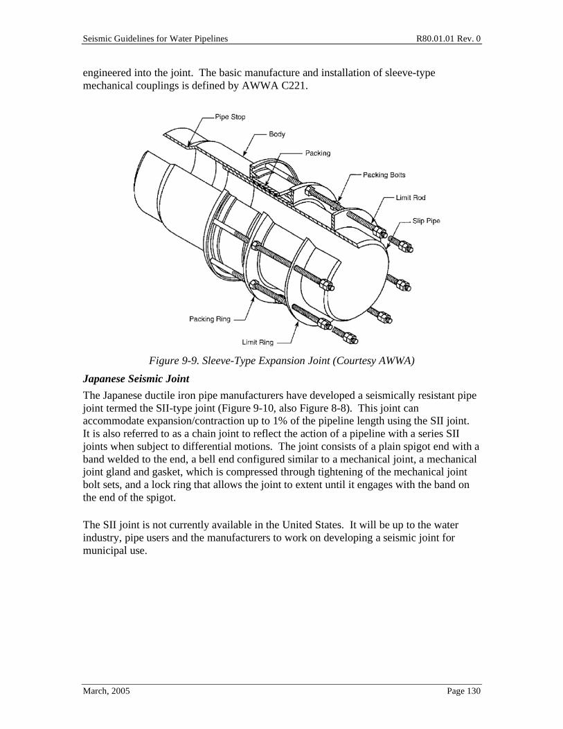
Seismic Guidelines for Water Pipelines R80.01.01 Rev. 0
March, 2005 Page 130
engineered into the joint. The basic manufacture and installation of sleeve-type mechanical couplings is defined by AWWA C221.
Figure 9-9. Sleeve-Type Expansion Joint (Courtesy AWWA)
Japanese Seismic Joint
The Japanese ductile iron pipe manufacturers have developed a seismically resistant pipe joint termed the SII-type joint (Figure 9-10, also Figure 8-8). This joint can accommodate expansion/contraction up to 1% of the pipeline length using the SII joint. It is also referred to as a chain joint to reflect the action of a pipeline with a series SII joints when subject to differential motions. The joint consists of a plain spigot end with a band welded to the end, a bell end configured similar to a mechanical joint, a mechanical joint gland and gasket, which is compressed through tightening of the mechanical joint bolt sets, and a lock ring that allows the joint to extent until it engages with the band on the end of the spigot.
The SII joint is not currently available in the United States. It will be up to the water industry, pipe users and the manufacturers to work on developing a seismic joint for municipal use.

Seismic Guidelines for Water Pipelines R80.01.01 Rev. 0
March, 2005 Page 131
Figure 9-10. Japanese SII Joint
TerraBrute Joint
The TerraBrute1 joint is a chain-type joint configured for use with C900 PVC pipe (Figure 9-11). In concept, the joint allows some amount of axial movement of the adjacent PVC pipes, before the steel rings stop against a steel insert piece. For corrosion resistance, the manufacturer reports that the steel ring and pins shown in Figure 9-11 may be replaced with polyurethane rings and stainless steel or nylon pins. Tests of this type of joint are being made by the manufacturer as of early 2005.
Figure 9-11. TerraBrute Joint
1 Courtesy Ipex, www.ipexinc.com

Seismic Guidelines for Water Pipelines R80.01.01 Rev. 0
March, 2005 Page 132
10.0 Distribution Pipelines The two most common types of pipelines used in new water pipe installations in the United States are polyvinyl chloride (PVC) and ductile iron (DI) pipes. The most common joint used in these installations (and the least expensive) is the "push-on" rubber gasketed joint. PVC pipe is relatively cheap, and is corrosion resistant. Contrary to some claims made by manufacturers, DI installations of this type have not proved to be "seismically invulnerable", as evidenced in the 1994 Northridge and 1995 Kobe earthquakes. Further, DI may be corrosion sensitive, unlike less expensive PVC materials. The DI manufacturers have responded by employing polyethylene external liners, but some owners remain skeptical than pin holes in the liners will lead to permanent damp environments, leading to more rapid corrosion than otherwise. This is not to say that PVC pipe is ideal, in that any significant bending on the pipe will often lead to tensile rupture (split), with break more common than leak.
Given these issues, the Guidelines describe alternative installations, as follows:
• Standard installation (per AWWA standards) (least expensive)
• Enhanced throw joint installation (longer travel available at gasketed joints)
• Lock-type joints (inserted binders that prevent pull apart, after the pipe is installed)
• Mechanical joints (friction-gland systems)
• Semi-restrained joints (similar to Japanese S-II type joints), which allow some axial pull and some rotation at each joint (most expensive).
The Guidelines consider relative costs for each installation; recommended range limits for ground velocity and ground deformation for each joint. As of early 2005, manufacturer's catalogs often do not include sufficient engineering data (pull out strengths, stiffnesses) to validate engineering design assumptions required when using either the ESM or FEM methods. The chart method recommendation infer certain capacities for the joints, but are still largely based on engineering judgment. It is intended that pipe manufacturer's supply more quantified information about their products, so that cost-effective and optimal design strategies can be implemented.
The images of pipe joints in this chapter were adopted from a test program for pipe joints by Meis, Maragakis and Siddharthan (2003). The images are of test assemblies (prior to test) for common size 4" to 12" CI, DI, PVC and PE pipes.

Seismic Guidelines for Water Pipelines R80.01.01 Rev. 0
March, 2005 Page 133
10.1 Cast Iron Pipe Cast iron pipe with bell and spigot lead caulked unrestrained joints have been used in the US since 1817. Today (2005), cast iron pipe is either most common or second most common pipe material in the ground for most US water utilities.
Graphite flakes are distributed evenly through the material. They have a darkening effect on the material, giving it its proper name of "gray cast iron". Historically, the most common type of caulking at the bell and spigot joint has been poured lead with tightly tamped oakum material (Figure 10-1). These joints tend to become rigid with age, helping make the joint more vulnerable to pull out / leak in earthquakes.
Figure 10-1. Cast Iron Pipe – Bell and Spigot Joint
10.2 Ductile Iron Pipe Ductile Iron pipe is manufactured to AWWA C151.
Ductile iron differs from cast iron in that its graphite is spheroidal or nodular in form instead of flakes, resulting in greater strength, ductility and toughness.
Figure 10-2 shows four types of ductile iron pipe joints that are often used in water distribution systems. The most common of these joints is the simple push-on joint, Figure 10-2(a). A rubber ring gasket is compressed during the insertion of the spigot end into the joint, forming a water-tight seal at the joint. This joint is typically the least expensive for purchase and installation, and thus is the most commonly used. Figure 10-3 shows ductile iron pipe with bell and spigot push-on type joints of the type shown in Figure 10-2(a).
From an earthquake resistance point of view, joint (a) provides some capacity to resist moderate to strong ground shaking, as long as the gasket is not deteriorated and the spigot

Seismic Guidelines for Water Pipelines R80.01.01 Rev. 0
March, 2005 Page 134
end is well inserted into the bell end. The insertion distance using manufacturer's common recommendations is often about 1 inch, for a pipe that is often about 16 feet long. Using the fragility analytical techniques in (ALA, 2001), it would be unlikely to experience more than one joint pull out (complete break) in 10,000 joints at a PGV of 30 inches per second.
Figure 10-2. Common Ductile Iron Pipe Joints
With sufficient tensile force applied to joint (a), the pipe will slip out. The tensile force could be from water pressure, from extreme cold weather, or from some form of PGV or PGD. For the former two cases, concrete anchor blocks are often poured at locations with change in direction. These Guidelines require the anchor blocks to be designed for both hydrostatic and hydrodynamic loads; if the anchor blocks are not designed for hydrodynamic loads, then restrained pipe joints could be used for the first 3 pipe segments either side of the anchor block unless calculations show otherwise. However, these anchor blocks provide little resistance for imposed PGDs. On an empirical basis, an imposed PGD (in unknown direction) of 1 inch would lead to an equivalent break rate of about 0.25/1000 feet; such a high break rate will generally lead to poor network performance. Note: if the PGD is applied parallel to the pipe, the break rate is about 10 times higher than if the PGD is applied transverse to the pipe).

Seismic Guidelines for Water Pipelines R80.01.01 Rev. 0
March, 2005 Page 135
Figure 10-3. Ductile Iron Pipe – Push On Joint
Figure 10-4 shows a ductile iron pipe joint of the type shown in Figure 10-2(b). The spigot end includes a weldment with beveled end, so that it can be inserted into the bell end, The weldment is a steel bar bent to fit around the circumference of the spigot end and welded to the pipe surface. After the joint is assembled, the restraining snap-ring snaps into a groove in the bell end behind the weldment. When a tension force is applied to the joint, the weldment bears against the retaining ring and prevents the two pipes from pulling apart.
Figure 10-4. Ductile Iron Pipe – Push On Joint with Retaining Ring

Seismic Guidelines for Water Pipelines R80.01.01 Rev. 0
March, 2005 Page 136
Figure 10-5 shows a ductile iron pipe joint of the type shown in Figure 10-2(c). The gasket has embedded stainless steel locking segments in the form of angled teeth. Under tensile loading, the teeth grip into the spigot pipe, and provide some restraint against pull out.
Figure 10-5. Ductile Iron Pipe – Push On Joint with Gripper Gaskets
Figure 10-6 shows a ductile iron pipe joint of the type shown in Figure 10-2(d). The bolted-on collar is made of cast iron (could be other materials) and the collar is held tightly to the outside body of the spigot and bell end pipes using wedge screws fitted with slanted teeth that are tightened firmly and digs into the pipe surface. One collar is bolted to a similar collar on the opposite side of the joint.
Figure 10-6. Ductile Iron Pipe – Push On Joint with Bolted Collar
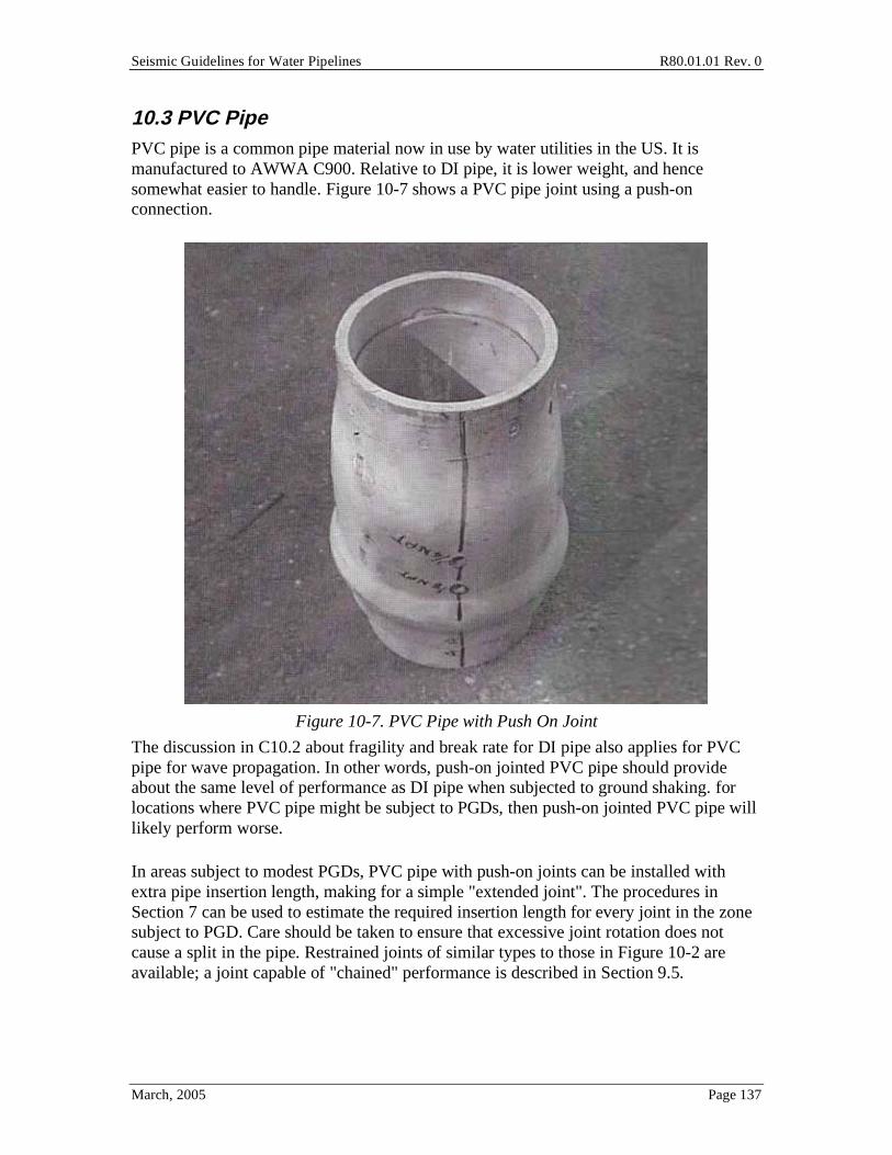
Seismic Guidelines for Water Pipelines R80.01.01 Rev. 0
March, 2005 Page 137
10.3 PVC Pipe PVC pipe is a common pipe material now in use by water utilities in the US. It is manufactured to AWWA C900. Relative to DI pipe, it is lower weight, and hence somewhat easier to handle. Figure 10-7 shows a PVC pipe joint using a push-on connection.
Figure 10-7. PVC Pipe with Push On Joint
The discussion in C10.2 about fragility and break rate for DI pipe also applies for PVC pipe for wave propagation. In other words, push-on jointed PVC pipe should provide about the same level of performance as DI pipe when subjected to ground shaking. for locations where PVC pipe might be subject to PGDs, then push-on jointed PVC pipe will likely perform worse.
In areas subject to modest PGDs, PVC pipe with push-on joints can be installed with extra pipe insertion length, making for a simple "extended joint". The procedures in Section 7 can be used to estimate the required insertion length for every joint in the zone subject to PGD. Care should be taken to ensure that excessive joint rotation does not cause a split in the pipe. Restrained joints of similar types to those in Figure 10-2 are available; a joint capable of "chained" performance is described in Section 9.5.

Seismic Guidelines for Water Pipelines R80.01.01 Rev. 0
March, 2005 Page 138
10.4 High Density Polyethylene Pipe HDPE pipe is a newer pipe material now in limited use by water utilities in the US. It is manufactured to AWWA C906. HDPE is made from high density extra high molecular weight materials. HDPE pipe is commonly used for natural gas distribution lines, and sometimes for potable water pipes. Unlined HDPE pipe should not be used through contaminated soils.
The joints between segments of pipe are created by placing an elevated temperature metal plate between two pipe segments held within a clamping assembly, thus melting the plastic, and then removing the metal plate and forcing the two melted ends together. The finished joint is often called a fusion butt weld. Beads of plastic form outside and inside the pipe at the joint location.
Figure 10-7 shows a HDPE pipe with three butt welded fusion joints.
Figure 10-8. PE Pipe with Three Fusion Butt Welded Joints
10.5 Performance of Common Pipe Joints Under Axial Loads One of observed the failure mechanisms of water distribution pipes in earthquakes is the crushing (relatively rare) or pull out (more common) of pipe joints. In order to select an appropriate pipe joint for a particular pipeline installation application, the user should understand the failure mechanism.

Seismic Guidelines for Water Pipelines R80.01.01 Rev. 0
March, 2005 Page 139
While there have been many instances of pipe damage in earthquakes, it is often difficult to get accurate descriptions of the failure modes. To provide failure mechanisms under a controlled environment, Meis et al (2003) have taken typical distribution pipes and broken them in the lab.
Figure 10-9. Ductile Iron Pipe Cross Section (After Failure)
Figure 10-9 shows the failure mode for a 8-inch ductile iron joint (push-on type) under compression loading. The figure shows the failed specimen, cut in half to expose the joint. The failure is the wrinkling of the spigot pipe as it bears against the inside of the bell end. With sufficient wrinkling, the spigot end tears, and the space that holds the rubber gasket gets enlarged, end eventually the pipe leaks.
The following are some observations about the failure modes (from test):
• For DI pipe, compression failure occurs at displacements of about 0.4 cm, and always at 0.8 cm.
• For CI pipe, compression failure occurs at displacements of about 2.5 cm. CI typically can resist double the load than comparable diameter DI pipe.
• For DI pipe with joint type c (gripper teeth), tension failure occurs at pull-out displacements ranging from 1.5 cm (12-inch pipe) to 4-5 cm (6-inch to 8-inch pipe)
10.6 Seismic Design Recommendations for Distribution Pipelines Distribution systems must blanket the service area wherever development exists. As such, avoidance of larger hazards is not feasible and therefore distribution systems must

Seismic Guidelines for Water Pipelines R80.01.01 Rev. 0
March, 2005 Page 140
cross hazards. Because of the high degree of redundancy in a distribution system, through looping and multiple supply points, distribution systems can be isolated at points of damage and service restored outside the hazard area in relatively short order. Within the hazard area, damage may be so extensive that repairs will take time and full service will be slow to return. Using the concept presented in Section 9.0 for bypassing flow around damage zones, owners can establish temporary services using fire hoses connected to hydrants and isolation valves to serve undamaged areas or initially repaired areas.
Distribution pipelines are assumed to be less than 16-inch in diameter. Tables 7-5 through 7-19 summarize the recommended design approach for distribution pipeline facilities for a particular level of performance. The following describe the distribution pipeline seismic design approaches:
Class A – Standard Design Practice. No special seismic design considerations are warranted under this design class. Where additional valves are noted, the requirement would be for isolation valves to effectively isolate the hazard area from non-hazard areas and provide enough flexibility in bringing service back into hazard areas as repairs progress.
Class B – Restrained Joint Design. This class of design would accommodate low to moderate settlements or deflections in the pipeline through the use of restrained joints and connections, which would be needed within any hazard area to minimize the potential for pipeline failure due to joint pull-out. Provide additional valves (generally under 500-foot spacing, 4 valves at 4-way crossings, 3 valves at tees, adjacent to each hazard zone, etc.)
Class C – Upgraded Pipe Material Design. This class of design would be used for more critical installations where ground movement becomes more significant and typical segmented pipeline design has proven inadequate. Pipelines can be designed with ductile welded steel pipe or HDPE pipe, which would have continuously restrained joints that are capable of accommodating significant ground deformations. Restrained joint PVC and ductile iron pipe may be appropriate, augmented by enhanced-throw joints, lock ring joints, or other means that prevent pipe pull-out with ground motion and deformation.
Class D – Quantified Seismic Design Approach. This class of design requires adherence to the methodology and approach described in Section 7.4. This class of design is reserved for critical distribution facilities and high risk hazard conditions. The design may ultimately be similar to Class C, but with increased knowledge of the extent of the geotechnical hazard and the PGV and PGD demands on the pipe and pipe joints. Bypass systems (flex hose with valves) may be a suitable alternative.
10.7 Standard Installation Based on AWWA Guidelines In most areas of the United States, standard practice for installation of new distribution system pipelines relies primarily on PVC or DI pipe. A few utilities use other materials,

Seismic Guidelines for Water Pipelines R80.01.01 Rev. 0
March, 2005 Page 141
such as welded steel pipe (in high seismic hazard areas), and HDPE pipe (limited usage since mid 1990s, used in high PGD hazard areas).
The standard of practice for PVC and DI materials is described in good detail in AWWA Manual 23: PVC Pipe – Design and Installation and AWWA Manual 41: Ductile-Iron Pipe and Fittings. These publications define the methodology and approach for design of pipe systems for the respective materials. Owners should refer to these publications when undertaking design of distribution system projects using these two materials.
Both PVC and DI pipe design typically utilizes push-on rubber gasketed joints, except at fittings and valves. This type of design is appropriate, even for high ground shaking hazard areas, as long as good soils and geology exist (low chance for PGDs).
Where soils and geology are not favorable, the Guidelines suggest that some form of extended or restrained joints be used with DI or PVC pipe. Alternatively, welded steel pipe or HDPE pipe can be used, both exhibiting superior resistance to pull-out due to welded or fused joints, which creates continuous pipe (not segmented) construction. Alternatively, bypass systems might be installed.
Welded steel pipe is another common distribution system material. When constructed using welded joints, this material can provide good resistance to seismically induced ground motion and permanent ground deformations. Smaller diameter steel pipe (generally 20-inch and smaller) must use only single lap welded joints, as it is near impossible to fillet weld from the inside. Single lap-welds are not sufficiently ductile to withstand settlements much over 12 inches (perpendicular to the pipe) or 2 to 3 inches (parallel to the pipe). Double lap-welded pipe joints (generally impractical for smaller diameter pipe) are much better for ductility than single-lap welded pipe. Use of butt-welded joints provides a major increment of strength and ductility to withstand substantial amounts of ground movement transverse and parallel to the pipe. The standard of practice for welded steel pipe is described in good detail in AWWA Manual 11. Manual 11 does not suitably cover seismic loading.
For HDPE pipe, AWWA publishes a standard specification, AWWA C906 – AWWA Standard for Polyethylene (PE) Pressure Pipe and Fittings, 4-inch (100 mm) through 63-inch (1,575 mm), for Water Distribution and Transmission. This specification describes the material and workmanship requirements for HDPE pipe. Each manufacturer has a standard design and installation manual that owners should refer to when undertaking design of an HDPE pipeline.
As noted in Tables 7-5 through 7-8, improved system performance (post seismic event) can be achieved through use of distribution system redundancy and strategically located isolation valves that allow the system to be brought back into service after isolating out the damaged areas after the seismic event.

Seismic Guidelines for Water Pipelines R80.01.01 Rev. 0
March, 2005 Page 142
The following paragraphs describe joint types that can further augment the post seismic event integrity of a distribution system. Table 10-5 give some cost and suggested use for specialized joints for distribution pipes.
Connection/Joint Type and Unit Cost1
Application
Restrained Mechanical
Joint
Lock-Type Restrained
Joint2
Enhanced Throw
Sleeve-Type Exp. Joint
Japanese S-II Seismic Joint
36-inch @ $55/LF 24-inch @ $20/LF 18-inch @ $13/LF
Differential Axial Movement
Very small movements
Very small movements
Very Good Good to 1% of pipe length
Differential Angular Movement
Very small deflections
Very small deflections
N/A Fair
Prevent Pipe Joint Pullout Very Good Very Good Good Very Good
Differential Offset Movement
N/A N/A N/A Very Good
Notes: 1. Costs based on basic configuration for materials only as quoted from manufacturers in December 2004. Consult manufacturers for specific application and needs.
2. Cost represents increase from standard push on joint DIP.
Table 10-5. Summary of Alternative Joint Designs for Distribution Systems
Enhanced-Throw Joint Installations
Enhanced-throw joints are specialty pipe fittings manufactured for applications where expansion/contraction is expected in the distribution system. These joints have deeper bells that allow for additional axial movement than standard bells. Welded steel pipe joints can be manufactured with a deeper bell and double gasket joint assembly, as illustrated in Figure 10-10. The double gasket assembly is possible only with steel joint rings. DI pipes are provided with standard joint configurations that cannot be modified for enhanced throw. PVC pipes could be installed with long insertions to simulate an enhanced throw joint, but pipe rotation capability is uncertain. The water industry and PVC and DI pipe manufacturers would have to develop new joint designs and castings/molds for a new enhanced throw joint.
The sleeve-type expansion joints described in Section 9 allow for significant joint throw. These joints should be located strategically to allow for ground motion and deformation, while the pipeline is allowed to expand and/or contract with that motion and deformation. Sleeve-type expansion joints must be installed in a vault for periodic maintenance associated with tightening the packing gland and monitoring movement. This type of joint is illustrated in Figure 9-9.

Seismic Guidelines for Water Pipelines R80.01.01 Rev. 0
March, 2005 Page 143
Figure 10-10. Enhanced Throw Welded Steel Pipe Joint (unrestrained)
Lock-Type Joint Installations
Lock-type joints are standard push-on joints that include a mechanical lock ring that mechanically engages the pipe surface to prevent pipe pull out. These joints can be used with the enhanced-throw joints to maintain the pipeline integrity during seismic motions and resulting ground deformations. Refer to Figure 10-11 for an illustration of this joint type.
A lock-ring joint that can take 1 to 2 inches of axial expansion before locking up will generally provide a reasonable design for distribution pipe location in soils with high susceptibility to settlements.
Table 10-11. Summary Lock-Type Joint (Courtesy of AWWA)
Mechanical Joint Installations
Mechanical joints, when properly restrained, also act to prevent pipe pull-out due to excessive axial movement of the pipeline. Refer to Figure 10-12 for a sketch of a typical mechanical joint.

Seismic Guidelines for Water Pipelines R80.01.01 Rev. 0
March, 2005 Page 144
Table 10-12. Restrained Mechanical Joint (Courtesy of AWWA)
Semi-Restrained Joint Installations
The Japanese have developed the S-II joint, designed for use with ductile iron pipe and providing for both axial and angular or offset motion of the pipeline. These joints are not commercially available in the United States, but have proven effective in the 1995 Kobe earthquake (about 100 km of such installation through highly susceptible liquefaction areas suffered no leaks). The joint is illustrated in Figure 9-10. These Guidelines call this type of joint a "chained" joint.

Seismic Guidelines for Water Pipelines R80.01.01 Rev. 0
March, 2005 Page 145
11.0 Service and Hydrant Laterals Appurtenances are those ubiquitous components connected to pipelines that serve a variety of functions with the most common being customer service and fire hydrant lateral connections. Customer services and fire hydrant laterals respectively refer to the piping and associated hardware used to convey water from the distribution main to a customer’s meter or fire hydrant. Other appurtenances include blow-offs, pressure relief valves, vacuum valves, air valves, test stations and the like. Traditionally, these are non-engineered for seismic conditions, and the hardware used is governed by ease of installation and maintenance economics. Significant numbers of appurtenances have suffered damage during earthquakes. Post earthquake damage surveys that tracked service laterals damage revealed they constituted roughly 20% of all distribution system repairs in several surveys (Table 11-1 provides examples). Seismic failure of the appurtenance pressure boundary is more likely to lead to a leak rather that the more serious break that would necessitate immediate shutdown of the pipe until repairs are enacted. Nevertheless, all damaged appurtenances eventually
will need to be repaired to restore the water system to its pre-earthquake condition, and
this cost can be large considering that mobilization and excavation effort for a buried pipe
repair is about the same as that to repair a buried service.
Because the large numbers of appurtenances and the fact those tend to be non-engineered for seismic conditions, this section presents seismic design considerations to mitigate appurtenance damage in earthquakes.
Earthquake Numbers of Service Repairs
Numbers of Pipe Repairs
Service-to-Pipe Repair Ratio
1994 Northridge1 (Toprak, 1998)
208
1,0132
1 to 5
1989 Loma Prieta East Bay Service Area (Eidinger, et al, 1995)
22
113
1 to 5
1971 San Fernando (NOAA, 1973)
557
856
1 to 2
Notes 1. Numbers of field repair records. 2. Includes repairs to hydrants.
Table 11-1. Ratio of service to pipe repairs from earthquake damage surveys.
11.1 Typical Customer Service and Fire Hydrant Lateral Figure 11-1 depict typical customer service installations defined as the piping connecting the water main to the customer meter. Isolation valves are located at the main and meter.
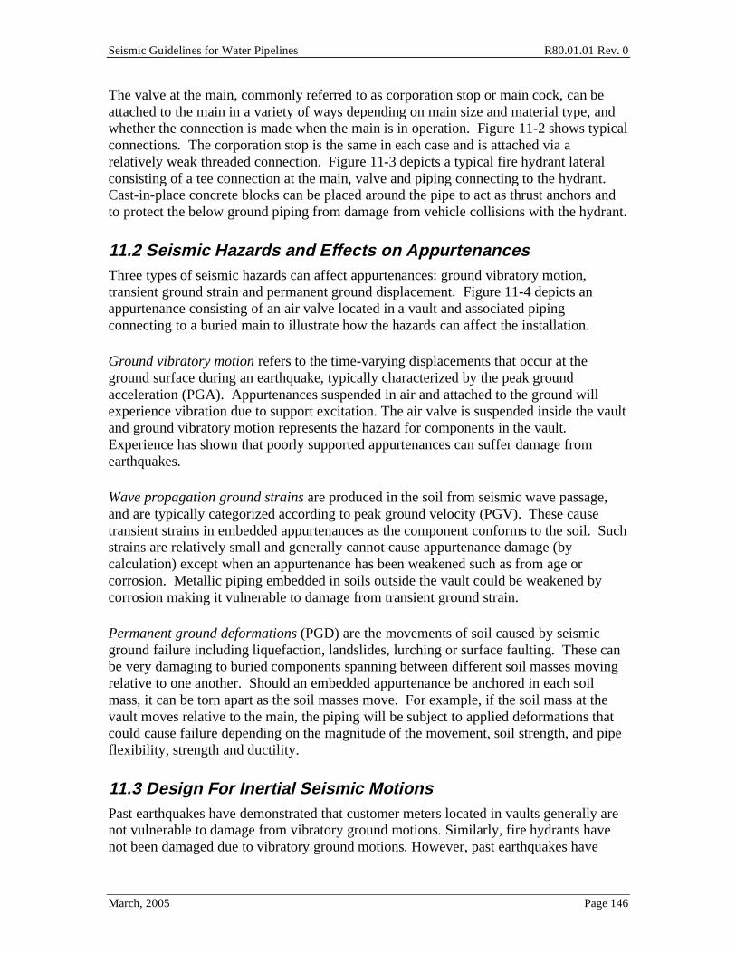
Seismic Guidelines for Water Pipelines R80.01.01 Rev. 0
March, 2005 Page 146
The valve at the main, commonly referred to as corporation stop or main cock, can be attached to the main in a variety of ways depending on main size and material type, and whether the connection is made when the main is in operation. Figure 11-2 shows typical connections. The corporation stop is the same in each case and is attached via a relatively weak threaded connection. Figure 11-3 depicts a typical fire hydrant lateral consisting of a tee connection at the main, valve and piping connecting to the hydrant. Cast-in-place concrete blocks can be placed around the pipe to act as thrust anchors and to protect the below ground piping from damage from vehicle collisions with the hydrant.
11.2 Seismic Hazards and Effects on Appurtenances Three types of seismic hazards can affect appurtenances: ground vibratory motion, transient ground strain and permanent ground displacement. Figure 11-4 depicts an appurtenance consisting of an air valve located in a vault and associated piping connecting to a buried main to illustrate how the hazards can affect the installation.
Ground vibratory motion refers to the time-varying displacements that occur at the ground surface during an earthquake, typically characterized by the peak ground acceleration (PGA). Appurtenances suspended in air and attached to the ground will experience vibration due to support excitation. The air valve is suspended inside the vault and ground vibratory motion represents the hazard for components in the vault. Experience has shown that poorly supported appurtenances can suffer damage from earthquakes.
Wave propagation ground strains are produced in the soil from seismic wave passage, and are typically categorized according to peak ground velocity (PGV). These cause transient strains in embedded appurtenances as the component conforms to the soil. Such strains are relatively small and generally cannot cause appurtenance damage (by calculation) except when an appurtenance has been weakened such as from age or corrosion. Metallic piping embedded in soils outside the vault could be weakened by corrosion making it vulnerable to damage from transient ground strain.
Permanent ground deformations (PGD) are the movements of soil caused by seismic ground failure including liquefaction, landslides, lurching or surface faulting. These can be very damaging to buried components spanning between different soil masses moving relative to one another. Should an embedded appurtenance be anchored in each soil mass, it can be torn apart as the soil masses move. For example, if the soil mass at the vault moves relative to the main, the piping will be subject to applied deformations that could cause failure depending on the magnitude of the movement, soil strength, and pipe flexibility, strength and ductility.
11.3 Design For Inertial Seismic Motions Past earthquakes have demonstrated that customer meters located in vaults generally are not vulnerable to damage from vibratory ground motions. Similarly, fire hydrants have not been damaged due to vibratory ground motions. However, past earthquakes have

Seismic Guidelines for Water Pipelines R80.01.01 Rev. 0
March, 2005 Page 147
shown that other appurtenances can be susceptible to damage, especially components that are mounted in a relatively flexible manner (like inverted pendulums within or outside of a vault) and those that have non-ductile connections. Inverted pendulum assemblies seem to have been particularly prone to damage if the vertical riser pipe had suffered the effects of corrosion. An example is the air valve mounted on an aboveground large diameter pipeline as shown in Figure 11-5. The air value has the potential for dynamic amplification due to its support by piping acting as a flexible inverted pendulum (vertical cantilever). Also, the pipe connections in Figure 11-5 are threaded; threaded connections often have less capacity than the main pipe to accept bending moments; may not have been totally engaged during installation; may have suffered from aging/corrosion; and in general have low ductility (inability to accept local yielding for multiple cycles). Another example is the combination valve arrangement (Figure 11-6) having a vacuum release valve cantilevered above the pipe and an air valve cantilevered from the vacuum valve. The air valve is particularly vulnerable because the vibratory motions are amplified by the vacuum valve support structure (inverted pendulum).
It is clear that if the inverted pendulum assembly has been designed for seismic loading, then the performance will be adequate (barring corrosion or improper installation). Section 4 provides the level of ground motion that should be considered at such installations.
From field observation in past earthquakes (including San Simeon 2003, Loma Prieta 1989), it is apparent that "standard" installations of such assemblies have led to seismic inertial-induced damage on small diameter pipe (Figure 11-5 style installation) as well as on major transmission pipelines (Figure 11-6 style installation). Damage seems to be either very sporadic or non-existent when local PGA values are less than 0.15g, even for non-seismically designed installations. Accordingly, the Guidelines suggest that such installations need no special seismic design requirement in design at sites with PGA < 0.15g. As the extra cost to seismically design an assembly like those in Figures 11-5 or 11-6 should be in most cases very small, we suggest that a simple design check for the riser pipe (and its connections) should be done; with an allowance in pipe wall / connection styles for possible long term corrosion. To recognize that a standardized design will usually be desirable, a water utility would establish a suitable 475-year return period PGA motion for its entire service area, and then design all such inverted pendulum-type assemblies for 2.5 times the PGA. We recommend that no "response modifier" be used; instead, the entire assembly should be designed for the elastically-computed motions, while keeping maximum pipe component stresses below yield. Design recommendations follow.
PGA Design Approach 0 to 0.15g Standard installation Over 0.15g Design to elastic limits
Table 11-2. Recommended appurtenance design for vibratory ground motion.

Seismic Guidelines for Water Pipelines R80.01.01 Rev. 0
March, 2005 Page 148
11.4 Design For Wave Propagation Ground Strains (PGV) Corrosion of metallic appurtenances can weaken them so that even the relatively small strains caused by seismic wave passage are sufficient to cause failure. Copper service laterals are an example where one west coast utility has altered its approach to better protect against corrosion. Originally, copper services were electrically insulated only at the customer meter but left electrically connected to metallic mains with the rationale that the main would protect the service because the pipe would act as the anode vis-à-vis the service acting as a cathode. At a later date, copper services were also electrically insulated at the corporation stop to reduce corrosion in metallic mains; but so isolating the service produced cases of copper service failures due to corrosion. This led to the current practice for new service installations of using plastic coated copper service hardware and connection with magnesium anode as illustrated in Figure 11-7. Costs associated with enhanced service corrosion protection were deemed worthwhile versus future maintenance costs associated with service replacement due to corrosion. Accordingly, good corrosion protection programs will mitigate damage to appurtenances from transient ground strains resulting from earthquake wave passage. Design recommendations follow.
PGV Cost-Effective Design Approach
0 to 10 in/sec
Standard installation
Over 10 in/sec
Provide explicit corrosion protection to buried metallic
appurtenances
Table 11-3. Recommended appurtenance design for transient ground strain caused by seismic wave passage
11.5 Design For Permanent Ground Displacement Permanent ground displacement represents the most serious hazard for buried appurtenances. Figure 11-8 illustrates one typical mechanism. The appurtenance is located in an unstable soil mass that is subject to movement to the south, and connected to a north-south oriented water main that is anchored to another east-west oriented water main that is located in a stable soil mass. The relative motions cause stresses to develop in the appurtenance with the key location being at the attachment to the main (point A in Figure 11-8). In this example, the north-south run of main does not displace with the moving soil due to its being anchored in the stable soil mass to the north. Whether the appurtenance pressure boundary fails and a leak develops depends on the strength and flexibility of the attachment.
• Strength. A relatively strong attachment can allow the appurtenance to shear through the soil thus having no loss of the pressure boundary.

Seismic Guidelines for Water Pipelines R80.01.01 Rev. 0
March, 2005 Page 149
• Flexibility. A flexible attachment can accommodate the relative displacements with no failure of the pressure boundary. Flexibility can be provided by mechanical hardware and/or material ductility.
11.5.1 Customer Services
Main cocks, typically made of brass castings, are relatively weak and possess low ductility due to the threaded connection into the main. The strategy for PGD-tolerant design is to uncouple the main cock from the (moving) soil. This can be achieved by providing a soft void space around the main cock so that a modest amount of relative motions can be distributed over the relatively flexible and ductile service tubing. One such device is the "service boot" (Figure 11-9) that one west coast utility uses in areas of known ground movements having a history of main cock failures. Figure 11-10 shows a photo of the service boot components. Figure 11-11 shows another style of installation having copper tubing routed several directions creating a flexible "swing joint" near the main. This latter design is not expected to be as effective as the service boot. Design recommendations follow.
PGD Cost-Effective Design Approach 0 to 2 inches Standard installation
2 to 12 inches Service boot Over 12 inches Case-specific custom design
Table 11-4. Recommended customer service designs for permanent ground displacement.
11.5.2 Fire Hydrant Laterals
Fire hydrant laterals are typically connected to the main with tee connections that possess significant strength and ductility (especially if the lateral branch pipe is welded steel). Therefore, the standard installation, having no special mechanical couplings to provide additional flexibility, is able to resist (probably modest) levels of PGD. However, it is clear that under excessive PGD, it is likely that failure of the lateral will occur at the main-to-branch attachment point. Table 11-5 provides design recommendations. The magnitude of PGD beyond which special flexible coupling devises are cost-effective is difficult to quantify. Life-cycle cost must be considered on a case-by-case basis. Dresser-type couplings have the potential for increased maintenance costs due to leakage over time (versus a continuous pipe). EBAA flextend (or equivalent) couplings are relatively expensive leading to high installation costs versus the low likelihood that seismic PGD will affect a particular hydrant installation. Hydrant installations having histories of actual failures due to PGDs are candidates for special coupling devices as these will likely experience additional PGDs in future earthquakes.
The Guidelines recommend one dresser-type coupling for PGDs up to 3 inches; and two dresser-type couplings for PGDs up to 12 inches. If the direction of the PGD is axial along the lateral (like a hydrant placed in a slide on the fill side of a road, while the pipe is in the stable cut side of the road), then the couplings should be restrained. Flextend-type couplings can be used for large PGDs. Other design strategies could be used for

Seismic Guidelines for Water Pipelines R80.01.01 Rev. 0
March, 2005 Page 150
pipeline systems designed to be extremely reliable post-earthquake (such as dedicated fire-fighting systems).
PGD Cost-Effective Design Approach 0 to 2 inches Standard installation 2 to 12 inches Dresser-type coupling Over 12 inches EBAA flextend type coupling
Table 11-5. Recommended fire hydrant lateral designs for permanent ground displacement.
Figure 11-1. Elevation view of typical customer service installations

Seismic Guidelines for Water Pipelines R80.01.01 Rev. 0
March, 2005 Page 151
Figure 11-2. Elevation view of typical customer service connections to water main
Figure 11-3. Elevation view of a fire hydrant installation

Seismic Guidelines for Water Pipelines R80.01.01 Rev. 0
March, 2005 Page 152
Figure 11-4. Example air valve installation to illustrate seismic hazards. Buried portion vulnerable to seismic wave propagation and permanent ground movements, and portion
suspended inside vault vulnerable to vibratory ground motions
Figure 11-5. Elevation view of 1-inch air valve installation on pipeline
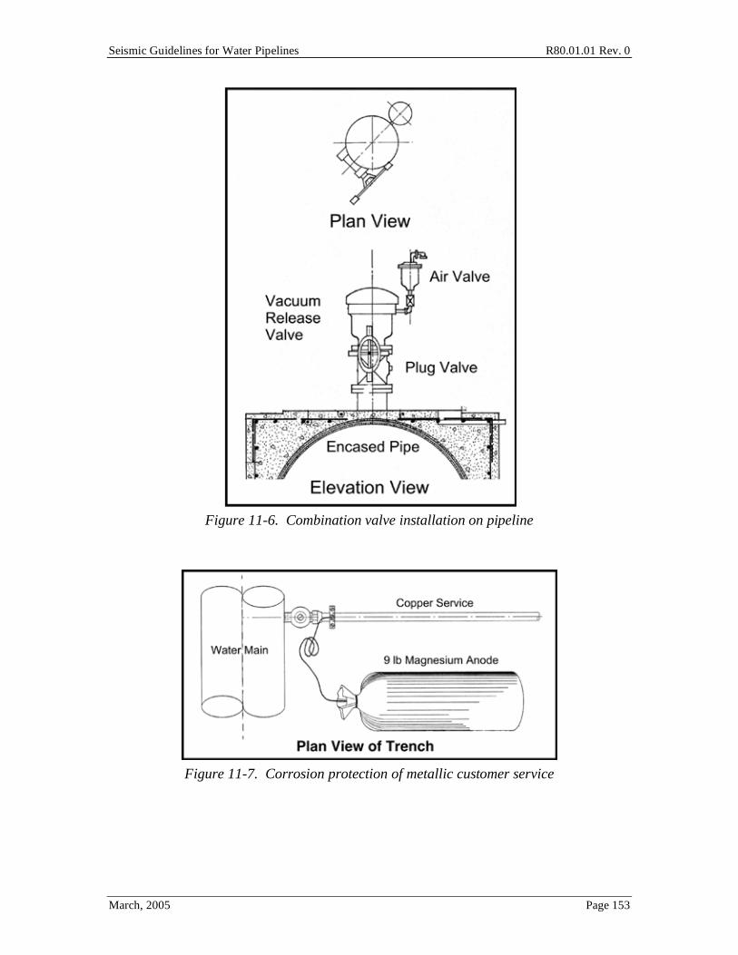
Seismic Guidelines for Water Pipelines R80.01.01 Rev. 0
March, 2005 Page 153
Figure 11-6. Combination valve installation on pipeline
Figure 11-7. Corrosion protection of metallic customer service

Seismic Guidelines for Water Pipelines R80.01.01 Rev. 0
March, 2005 Page 154
Figure 11-8. Example of PGD mechanism affecting appurtenance
Figure 11-9. Side view of service boot.

Seismic Guidelines for Water Pipelines R80.01.01 Rev. 0
March, 2005 Page 155
Figure 11-10. Photo of service boot components: HDPE drain pipe and end cap (upper
left), two foam inserts (upper right), and visqueen sheeting (foreground)
Figure 11-11. Service Lateral Installation to Address PGDs

Seismic Guidelines for Water Pipelines R80.01.01 Rev. 0
March, 2005 Page 156
12.0 Other Components 12.1 EBAA Iron Ball Joints at Fault Crossings As outlined in other places in these Guidelines, EBAA "flextend" assemblies can be used to provide for a limited (usually around 12 inches) amount of pipeline movement. These assemblies have often been used to allow for limited wall uplift of water tanks without overstressing attached side-entry pipes.
In concept, these assemblies can also be installed in buried pipes to accommodate localized settlements, landslide and fault offset movements. However, when the amount of PGD to be accommodated starts becoming large (say 40 to 100 inches for fault offset); and the location of the PGD becomes uncertain (say at a fault crossing, where the actual rupture might be distributed over some uncertain location within a wide zone), then it is recommended that the FEM (Section 7.4) be performed to ensure that the pipe and EBAA flextend assemblies are not overloaded.
In the following example, the use of EBAA flextend assemblies were considered for a 42-inch diameter pipeline that was to be installed across a fault:
• The pipe is a 42-inch diameter butt welded pipe with wall thickness of 0.5 inches in the vicinity of the fault.
• Two 42-inch diameter ball joints are placed in the pipe. There is 27 feet separation distance between the centerlines of the two ball joints.
• One expansion joint is placed in the pipe, at a location between the two ball joints.
An analysis of the type outlined in Section 7.4 was performed, assuming transverse fault offset of 31 inches occurs midway between the two ball joints. The key results are as follows.
• One ball joint undergoes an angular rotation of 4.8 degrees; the other ball joint undergoes a rotation of 7.8 degrees.
• The expansion coupling undergoes an extension of about 4.3 inches.
• The ball joints carry low moment (under 5,000 kip-inches, due to friction), and 178 kips (tension).
• The expansion coupling carries low axial force (under 1 kip, by friction) and low moment (under 4,000 kip-inches).

Seismic Guidelines for Water Pipelines R80.01.01 Rev. 0
March, 2005 Page 157
• The 42-inch x 0.5 inch thick welded steel pipe near the assembly has maximum strains of ±0.07% (+22 ksi, -20 ksi). These strains (stresses) are low enough to preclude wrinkling.
Observations. The design with ball joints and expansion couplings will work for the assumed fault offset, provided:
• The fault offset occurs between the two ball joints.
• The fault offset does not exceed a certain amount. The maximum fault offset prior to pipeline failure is the amount of offset needed to cause one (or both) of the ball joints to reach their rotation capacity, or to cause the expansion joint to fail, or to overload the pipeline. At this time, EBAA –Iron does not manufacture a 42-inch diameter ball joint. However, the 36-inch diameter ball joint can withstand about 15 degrees offset; and a recent 48-inch diameter product can withstand about a 11 degree offset. (Note: actual degrees offset may vary somewhat, and would be verified in actual design). Assuming that a 36-inch diameter ball joint is used, and providing that the maximum ball rotation is 11 degrees (modest amount of conservatism), then the ball joints, if spaced at 27 foot intervals, could take a maximum of about (11/7.8) * 31 = 44 inches of fault offset.
• Once one ball joint reaches its rotation limit, it will either lock up and transfer moment to the opposing ball joint, or it will break. At this time, there is no experimental data to show what happens if the ball joint is rotated beyond its stop capacity; therefore, one might assume that it would fail. It might be prudent to include such a test as part of the procurement process. It is understood that EBAA tests these assemblies to resist internal pressure, and not mechanical loading due to excessive rotation of the ball joints (or elongation / compression of the expansion joints).
• This example shows an unequal amount of ball joint rotation for the two ball joints. This demonstrates that the effects of transverse fault offset, plus nearby pipe bends as is the case for this example, can tend to promote unequal accommodation of the fault offset by the two ball joints.
• The expansion joint is predicted to take 4.3 inches extension, for a 31 inch fault offset. It is relatively straight forward to design an expansion joint to take 4.3 inches of expansion. EBAA-Iron provides a device that takes 10 inches.
• The EBAA-Iron catalog shows maximum allowable lateral offset of 17 inches for a 30-inch diameter double-ball-and-single-expansion assembly, with 5.25 feet centerline to centerline, ball joint spacing. For the example application, it is assumed that additional spool pieces of straight pipe are inserted between the two ball joints, to make up a 27-foot long, centerline to centerline, ball joint spacing.

Seismic Guidelines for Water Pipelines R80.01.01 Rev. 0
March, 2005 Page 158
• By inserting additional straight pipe between the two ball joints, larger fault offsets can be accommodated. However, the pipe between the ball joints can be exposed to high bending moments due to imposed soil loading, if the pipe is buried. It is unknown if EBAA has tested their expansion joint assemblies to take concurrent bending moments. High transverse loading will tend to ovalize the pipe, possibly leading to leaks through the packing of the expansion joints.
• For above ground applications (or below ground applications where the entire ball joint – expansion joint system is enclosed in a vault or similar empty annular space), there is no lateral load applied to the pipe between the ball joints, and the expansion joint will not be exposed to simultaneous axial expansion plus high bending. For a below ground application where the ball and expansion joints are buried in soil, bending moment on the pipe between the rotation joints cannot be avoided; the wider the spacing of the ball joints, the higher the moment on the pipe between the ball joints. For design, the trade-off between ball joint spacing and the design of the pipe between the ball joints must be considered.
• If the fault offset can take place anywhere in a wide fault zone, then it may be necessary to include many ball joints and expansion joints through the fault zone. If the spacing between the ball joints is too wide, and if the soil is stiff, and the coefficient of friction between the pipe and the soil is high (like it normally is) then fault offset may break the pipe between the ball joints. If the spacing between the ball joints is very narrow, then the cost to install may be very high. If the amount of offset is large (say more than 50 inches) with a knife-edge movement, and if the pipe is large (say diameter over 48 inches), then it might be impractical to design a ball-joint-expansion joint type of assembly that can provide adequate margin; or possibly only at a cost higher than that for butt welded steel pipe. These issues should be considered in the actual design process.
If the hazard requires design for a large amount of fault offset (say 5 to 15 feet or more), it would seem apparent that a simple "two ball joints and an expansion coupling" type of assembly will not provide reliable performance. If one considers a series of such assemblies, higher offset can likely be accommodated, but careful design is suggested (reliance on catalog parts alone might not provide suitable assurance). A sufficient number of rotating parts and expansion sleeves may be adequate; but alternate systems (butt welded steel pipe) might provide more capacity, less chance of leak / maintenance issues over the service life, at possibly similar or lower installation costs.
12.2 Equipment Criteria While these Guidelines are specifically focused on pipes, there are a variety of other components that are part of the entire pipeline system. The following paragraphs provide (limited) guidance on recommended seismic practices for these items. These items are commonly found at large valve vaults, especially those with motor-operated or hydraulically-operated valves, pressure and flow instruments, and SCADA telemetry systems.

Seismic Guidelines for Water Pipelines R80.01.01 Rev. 0
March, 2005 Page 159
• Valves in Vaults
• In general, the valves are seismically rugged.
• Actuator and yoke should be supported by the pipe and neither should be independently braced to the structure or supported by the structure unless the pipe is also braced immediately adjacent to the valve to a common structure.
• Sufficient slack and flexibility is provided to tubing, conduits, or piping which supply air, fluid or power needed to operate the valve.
• Valves operators should not be near surrounding structures or components that could impact the valve during seismic excitation.
• The valve body should be strong enough to transmit the axial forces in the pipe. This might be an issue only if the valve is located quite near the source of PGD and the pipe exposed to the PGD outside the vault is connected to the valve inside the vault by continuous (welded or bolted) connections.
• Motor Control Centers (for motor operated valves)
• Must be floor mounted NEMA type enclosure.
• Anchorage must be evaluated for seismic loads. At least two anchor bolts should be used per Motor Control Center section.
• Anchorage of the Motor Control Center must be attached to the base structural members (not sheet metal).
• Avoid excessive eccentricities when mounting internal components.
• Do not mount components directly to sheet metal; instead, mount them to the structural frame metal. Otherwise, the sheet metal may vibrate and induce high seismic loads to the components; if the components are not qualified for these loads, they may fail to perform their function.
• Control Panels and Instrument Racks
• Anchorage must be evaluated for seismic loads.
• Can be wall-mounted.
• All door latches must be secured with locking devices.
• Wire harnesses or standoffs should be installed on cable bundles to preclude large deformation of bundles.
• Batteries and Battery Racks
• Battery cells can be lead-calcium, weighing 450 lbs. or less.
• Batteries should be supported on two-step or single tier racks which have x-bracing or other suitable bracing.
• Batteries should be restrained by side and end rails.

Seismic Guidelines for Water Pipelines R80.01.01 Rev. 0
March, 2005 Page 160
• Provide snug fitting crush-resistant spacers between cells.
• Racks must be anchored, and anchorage evaluated for seismic loads.
• Small gel-type batteries located inside control panels, and commonly used for SCADA-backup power, should be restrained.
• Above Ground Equipment Piping
• Provide sufficient flexibility at equipment connections and nozzles.
• Assure flexibility of pipe routed between buildings or across expansion joints.
• Assure that pipe has sufficient space to displace during seismic excitation without impacting other components or structures.
• Emergency Generators
• Emergency generators should be anchored directly to the structural floor, or mounted on a skid which is directly anchored to the structural floor. Vibration isolators should not be used unless confirmed by analysis or test (avoid qualification by vendor catalog assertion only unless proper test and qualification data supports the vendor catalog assertion). Components (batteries, day tanks, mufflers, electric panels, etc.) should all be seismically designed. Propane tanks should be anchored. Emergency generators should not rely on piped natural gas.
• Vibration Isolated Equipment
• Equipment (generators, air compressors and other rotating equipment) mounted on vibration isolators are vulnerable to damage in earthquakes. Vibration isolators for equipment essential to functionality of the facility should not be used. "Snubbed" vibration isolators should only be used if the "snubbing" devices are approved by the engineer as meeting the strength and operational requirements.
• Equipment Anchorage
• Equipment anchorage is an important consideration in the design to assure functionality. A majority of equipment failures due to seismic loads can be traced to anchorage failure. Below is a brief discussion regarding equipment anchors and situations to avoid during installation.
• Expansion anchors. The wedge type (or torque controlled expansion anchor) has been widely tested and has reasonably consistent capacity when properly installed in sound concrete. Other types of non-expanding anchors such as lead cinch anchors, plastic inserts, and lag screw shield are not as reliable and should not be used. Proper bolt embedment-length should be assured. Inadequate embedment may result from use of shims or high grout pads. Bolt spacing of about ten diameters is required to gain full capacity. Comparable spacing is required between bolts and free concrete edges. Expansion anchors should not be used for vibrating

Seismic Guidelines for Water Pipelines R80.01.01 Rev. 0
March, 2005 Page 161
equipment as they may rattle loose and provide no tensile capacity. All expansion anchors should be stamped with a letter on the exposed head, which relates to its full length; the lettering system should be shown on the drawings.
• Epoxy anchor bolts. Epoxy anchorage systems may be used for new construction in areas with limited edge distances or limited embedment depths, or in other areas, subject to the environmental limitations on epoxy systems. Inadequate embedment may result from use of shims or high grout pads. Bolt spacing of about ten diameters is required to gain full capacity. Comparable spacing is required between bolts and free concrete edges. Epoxy anchors should not be used for vibrating equipment. All epoxy anchors should be stamped with a letter on the exposed head, which relates to its full length; the lettering system should be shown on the drawings.
• Cast-in-Place Anchors. Properly installed, deeply embedded cast-in-place headed studs and j-bolts are desirable since the failure mode is ductile (steel governs). Properly installed undercut anchors with long embedment lengths behave essentially like cast-in-place bolts and are similarly desirable. Care should be taken to extend anchors through grout to provide required embedment in the concrete below. Bolt spacing and edge distance requirements are the same as for expansion anchors.
• Welded Anchors. Well designed and detailed welded connections to embedded plates or structural steel provide high capacity anchorage. There are some precautions: Avoid welding to light gage steel members if possible. Line welds have minimal resistance to bending moments applied about the axis of the weld. Puddle welds and plug welds used to fill bolt holes in equipment bases have relatively low capacity. Welded anchors in damp areas or harsh environments should be checked periodically for corrosion.
• The minimum design forces for anchorage and bracing of equipment and non-structural components and for structural design of these components should be as follows:
Fp = Z * I *Cp *Cf *Cg *Wp
where
ZI = the combined free field peak ground acceleration (should be taken for a 475-year return period motion) times an importance factor. For components that are considered critical for immediate post-earthquake operation, ZI should use I=1.5; or base Z using the 2,475 year motion for the site and I=1.0; whichever is larger. Or, base ZI on the 84th percentile motion for the site for the design-basis earthquake.
Seismic Guidelines for Water Pipelines R80.01.01 Rev. 0
March, 2005 Page 162
Cp = a factor to account for in-structure amplification, and some amount of
ductility capacity of the component. For components mounted at grade or below, generally set this factor to 1.0. For components mounted at second floor or higher locations in a structure, consider local building amplification. No ductility should be considered for drilled-in or epoxy anchors. Adjusting Cp downwards for ductility is not advised for any component required for immediate post-earthquake operation.
Cf = Flexibility coefficient as follows:
• 1.0 for rigid components, rigidly mounted and braced to the supporting structure or foundation. A component installation is considered rigid if the first mode natural period of vibration of the mounted assembly is 0.06 seconds or less.
• 2.0 for flexible components, or rigid components flexibly mounted such that the first mode natural period of vibration is greater than 0.06 seconds.
Cg = Grade mounting coefficient as follows:
• 1.0 for components mounted at or above grade.
• 0.67 for components mounted below grade.
• The effects of vertical ground motion should be evaluated together with the effects of horizontal ground motion and design should be for either of the following load cases:
Fe = Fh
or
Fe = Fh2
+ Fv2
whichever produces the most severe effects, prior to combination with other loads required by the building code.
• A minimum factor of safety of four (against average test failure capacity) should be used for expansion or epoxy anchors used for equipment anchorage. This factor of safety can be reduced to 2 if the anchors can be shown to be at least 97% reliable at that load level.
• Earthquake restraints for above ground small bore piping, raceway and conduit systems, as determined by typical building codes, are oriented to reducing life safety risk, by limiting the falling potential for these items. Post earthquake functionality of these systems is not assured by following the UBC or IBC codes, and in some cases, the UBC- or IBC-mandated support systems may increase the potential for functional failures. Restraint systems other than that required by the UBC or IBC codes may be used, if justified by the engineer.

Seismic Guidelines for Water Pipelines R80.01.01 Rev. 0
March, 2005 Page 163
The following equipment can be considered as structurally and reasonably functionally rugged, and need be designed only for the minimum anchorage forces and the other recommendations in these Guidelines and other applicable documents:
• Valves • Engines • Motors • Generators • Turbines • Hydraulic and Pneumatic Operators (limited yoke length) • Motor Operators (limited yoke length) • Compressors • Transformers with anchored internal coils
The following equipment can be considered as structurally rugged, and need be designed for the minimum anchorage forces and the other recommendations in these Guidelines and other applicable documents. In addition, if post-earthquake operability of the equipment is critical, functional seismic qualification should be addressed by a knowledgeable engineer. Functional seismic qualification may be based on test or experience with similar equipment.
• Air handling equipment and fans (except for those with vibration isolators) • Low and Medium Voltage Switchgear (< 13.8 kV) • Instrumentation Cabinets • Distribution Panels • Battery Chargers • Motor Control Centers • Instrument Racks • Batteries • Inverters • Chillers

Seismic Guidelines for Water Pipelines R80.01.01 Rev. 0
March, 2005 Page 164
13.0 References ASCE, Guidelines for the Seismic Design of Oil and Gas Pipeline Systems, prepared by the ASCE Technical Council on Lifeline Earthquake Engineering, D. Nyman Principal Investigator, 1984.
ASCE 7, Minimum Design Loads for Buildings and Other Structures; www.bssconline.org
American Lifelines Alliance, “Guideline for the Design of Buried Steel Pipe”, 2001.
AWWA Manual 11. Steel Water Pipe: A Guide for Design and Installation.
AWWA Manual 23. PVC Pipe – Design and Installation.
AWWA Manual 41. Ductile-Iron Pipe and Fittings.
Ballantyne, D., Earthquake Loss Estimation Modeling of the Seattle Water System, Kennedy/Jenks/Chilton Report No. 886005.00, Federal Way, WA, 1990.
Bartlett, S.F. and T.L. Youd, Empirical Prediction of Lateral Spread Displacement, Journal of Geotechnical Engineering, ASCE, Vol. 121, No. 4, pp.316-329), 1995.
CGS, http://www.consrv.ca.gov/dmg/
Cheng, L., “Aboveground Seismic Retrofit Schemes of Water Pipelines Crossing The Hayward Fault”, Proceedings of the 12th World Conference on Earthquake Engineering, New Zealand Society for Earthquake Engineering, Silverstream, Upper Hunt, New Zealand, 2000.
DelCol, P. R., Behaviour of Large Diameter Line Pipe Under Combined Loads, Thesis, Department of Civil and Environmental Engineering, U. of Alberta, Fall, 1998.
Eidinger, J., Maison, B., Lee, D., and Lau, B., “East Bay Municipal Utility District Water Distribution Damage in 1989 Loma Prieta Earthquake,” TCLEE Monograph No. 6, ASCE, 1995.
Eidinger, J., Avila, E., Editors, Guidelines for the Seismic Evaluation and Upgrade of Water Transmission Facilities, TCLEE Monograph No. 15, ASCE, January 1999.
Eidinger, J., et al, 2001, "Seismic Fragility Formulations for Water Systems," Report for the American Lifelines Alliance, R47.01.01, Revision 1, 2001 (http://homepage.mac.com/eidinger/)

Seismic Guidelines for Water Pipelines R80.01.01 Rev. 0
March, 2005 Page 165
Eidinger, J., Collins, F., Conner M., Seismic Assessment of the San Diego Water System, 6th International Conference on Seismic Zonation, EERI, Palm Springs 2002a.
Eidinger, J., O'Rourke, M., Bachhuber, J., Performance of a pipeline at a fault crossing, 7th National Conference on Earthquake Engineering, EERI, Boston, MA, July 2002b.
El Hamadi, K. and O'Rourke, M., Seismic damage to segmented buried pipelines, Earthquake Engineering and Structural Dynamics, May, vol. 19, No. 4, pp. 529-539, 1990.
FEMA-302, NEHRP Recommended Provisions for Seismic Regulations for New Buildings and Other Structures, Part 1 - Provisions, Federal Emergency Management Agency, February, 1997.
Hall, W. J. and Newmark, N.M., Seismic Design Criteria for Pipelines and Facilities, The Current State of Knowledge of Lifeline Earthquake Engineering: Proceedings, Technical Council on Lifeline Earthquake Engineering Specialty Conference, ASCE, New York, 18-34, 1977.
Heubach, William F., Editor, Seismic Screening Checklists for Water and Wastewater Facilities, TCLEE Monograph No. 22, ASCE, 2003.
Idriss, I.M. Response of Soft Soil Sites During Earthquakes, Proceedings, H. Bolton Seed Memorial Symposium, Berkeley, CA, May 1990, pp.273-290.
Ishihara, K. and M. Yoshimine, Evaluation of Settlement in Sand Deposits Following Liquefaction During Earthquakes, Soils and Foundations, Vol. 32. No.1, pp 173-188, 1995.
Jibson, R., Predicting earthquake-induced landslide displacement using Newmark's sliding block analysis, TRR 1411, Transportation Research boards, National Academy Press, Washington, DC, 1994.
JWWA, Seismic Design and Construction Guidelines for Water Supply Facilities, Japan Water Works Association, 1997.
Kennedy, R. P., Chow, A. W. Chow and Williamson, “Fault Movement Effects on Buried Oil Pipeline”, Journal of the Transportation Engineering Division, ASCE, Vol. 103, No. TE5, 617-633, 1977.
Knudsen, Keith L., Sowers, Janet M., Witter, Robert C., Wentworh, Carl M., Helley, Edward J., Preliminary Maps of Quaternary Deposits and Liquefaction Susceptibility, None-county San Francisco Bay Region, California: A Digital Database, U.S. Geological Survey, Open-File Report 00-044 Version 1.0, 2000.

Seismic Guidelines for Water Pipelines R80.01.01 Rev. 0
March, 2005 Page 166
Kubota, “Earthquake-Proof Design of Buried Pipelines”, Pipe Research Laboratory of Kubota Ltd. Tokyo, Japan, 1981.
Kubota, “Kubota Ductile Iron Pipeline Design Manual” 3rd Edition, Kubota Corporation, Tokyo, Japan, 1992.
Meis, Ronald D., Maragakis, E. Manos, Siddharthan, Raj, Behavior of underground piping joints due to static and dynamic loading, Technical report MCEER-03-0006, University of Nevada, Reno, November 17, 2003.
National Research Council, Liquefaction of soils during earthquakes, Committee on earthquake engineering, Commission on engineering and technical systems, National Academic Press, Washington, D.C., 1985.
Newmark, N. M., Effects of earthquakes on dams and embankments, Geotechnique, vol. 15, no. 2, pp. 139-160, 1965.
Newmark, N. M. and Hall, W.J., “A Rational Approach to Seismic Design Standards for Structures,” Proceedings of the Fifth World Conference on Earthquake Engineering, 2266-2277, 1973.
Newmark, N, M., “Seismic Design Criteria for Structures and Facilities Trans-Alaska Pipeline System,” Proceedings of the U.S. National Conference on Earthquake Engineering, EERI, Oakland, CA, 1975.
Newmark, N. W. and Hall, W. J., Pipeline Design to Resist Large Fault displacement, Proceeding of U.S. National Conference on Earthquake Engineering, Ann Arbor, Michigan, EEERI, 416-425, 1975.
Nielsen, Tor H., Preliminary Photo Interpretation Map of Landslide and Other Surficial Deposits of the Richmond 7-1/2' Quadrangle, Contra Costa and Alameda Counties, California, 1975.
NOAA, Earthquake Damage to Water and Sewage Systems, San Fernando, CA, Earthquake of February 9, 1971, Vol. 2, Utilities, Transportation and Sociological Aspects, National Oceanic and Atmospheric Administration, Washington, D.C., 1973.
O’Rourke, M. J. and Liu, X., Response of Buried Pipelines Subject to Earthquake Effects, MCEER Monograph No.3, Multidisciplinary Center for Earthquake Engineering Research, University at Buffalo, Buffalo, New York, 1999.
O’Rourke, M and Nordberg, C., Analysis Procedures for Buried Pipelines Subject to Longitudinal and Transverse Permanent Ground Deformation, Proceedings, 3rd US-Japan Workshop on Earthquake Resistant Design of Lifeline Facilities and Countermeasures for Liquefaction, 1991.

Seismic Guidelines for Water Pipelines R80.01.01 Rev. 0
March, 2005 Page 167
O’Rourke, T. D. and Trautmann, C.H., “Earthquake Ground Rupture Effects on Jointed Pipe,” The Current State of Knowledge 1981 – Proceedings of the Second Specialty Conference of the Technical Council on Lifeline Earthquake Engineering, ASCE, New York, 65-79, 1981.
O'Rourke, T., Wang, Y., Shi, P, Advances in Lifeline Earthquake Engineering, in Proceedings, 13th World Conference on Earthquake Engineering, Vancouver B.C, August 2004.
Rowe, D., “Computational Methods for Analysis of The Response of Buried Pipelines to Soil Movements and Ground Distortion,” Abatement of Seismic Hazards to Lifelines: Proceedings of a Workshop on Development on An Action Plan, Volume 5: Papers on Gas and Liquid Fuel Lifelines and Special Workshop Presentations, Building Seismic Safety Council, Washington D.C., 83-104, 1987.
Sadigh, K., Chang, C.Y., Egan, J.A., Makdisi, F., Youngs, R.R, "Attenuation Relationships for Shallow Crustal Earthquakes Based on California Strong Motion Data", Seismological Research Letters, v. 68, No. 1, p. 180, 1997.
Scawthorn, C., Eidinger, J. and Schiff, A., Editors, Fire Following Earthquake, TCLEE Monograph No. 26, ASCE, 2005.
Timoshenko, S.P., Gere, J.H., Theory of Elastic Stability, 2nd Edition, McGraw-Hill, 1961.
Tokimatsu, A.M. and B. H. Seed, Evaluation of Settlements in Sands Due to Earth Shaking, Journal of Geotechnical Engineering, ASCE, Vol. 113, No.8, pp 861-878, 1987.
Toprak, S., Earthquake Effects on Buried Lifeline Systems, Ph.D. Dissertation, Cornell University, August, 1998.
Trautmann C.H., and O'Rourke, T.D., Load-Displacement Characteristics of a Buried Pipe Affected by Permanent Earth ground Movements, Earthquake Behavior and Safety of Oil and gas Storage Facilities, Buried Pipelines and Equipment, PVP-77, ASCME, New York, pp 254-262, June 1983.
Wang, L. R. L. and Yeh, Y. H., “A Refined Seismic Analysis and Design of Buried Pipeline for Fault Movement”, Earthquake Engineering and Structural Dynamics, Vol. 13, 75-96, 1985.
Wang, L.-J. and Wang, L. R. L., “Buried Pipelines in Large Fault Movement”, Lifeline Earthquake Engineering: Proceedings of the Fourth U. S. Conference, ASCE, New York, 152-159, 1995.

Seismic Guidelines for Water Pipelines R80.01.01 Rev. 0
March, 2005 Page 168
Wells, D. L., and Coppersmith, K. J., Updated empirical relationships among magnitude, rupture length, rupture area and surface displacement, Bulletin of the Seismological Society of America, 1994.
Working Group on California Earthquake Probabilities, Earthquake Probabilities in the San Francisco Bay Region: 2003-2032, USGS Open-File Report 03-214, U.S. Geological Survey, 2003.
Yashinsky, ed., San Simeon Earthquake of December 22, 2003 and Denali, Alaska Earthquake of November 3, 2002, TCLEE Monograph 28, 2004, chapter on water systems available at http://homepage.mac.com/eidinger/FileSharing14.html,
Youd, T. L., and Perkins, D. M., Mapping of liquefaction induced ground failure potential, Journal of Geotechnical engineering, ASCE, vol. 104, no. 4, p. 433-446, 1978.
Youd, et al., Liquefaction Resistance of Soils: Summary Report from the 1996 NCEER and 1998 NCEER/NSF Workshops on Evaluation of Liquefaction Resistance of Soils, Journal of Geotechnical and Geoenvironmental Engineering, ASCE, Vol.127, No. 10, pp. 817-833, Oct. 2001.

Seismic Guidelines for Water Pipelines R80.01.01 Rev. 0
March, 2005 Page 169
Commentary
Seismic Guidelines for Water Pipelines
Prepared for:
National Institute of Building Sciences
As part of the: American Lifelines Alliance
G&E Report 80.01.01, Revision 0 March, 2005

Seismic Guidelines for Water Pipelines R80.01.01 Rev. 0
March, 2005 Page 170
C1.0 Commentary These Guidelines are intended to be consistent with existing codes and expected community response. The UBC, IBC, and other codes have already established precedent on how the community is intended to respond following an earthquake. It is proper for the water pipelines to be designed consistent with the rest of the community and therefore assumed that the importance of certain facilities described in existing codes requires that not only the facility perform to a minimum level to protect human life during and following an earthquake, but that the water system perform adequately so that in an event of a disaster rescue crews will have adequate fire and potable water supplies to perform adequate emergency response activities. There is an assumed one to one relationship between the code facility design and the recommended performance of the pipeline service the facility. There is a certain level of risk for different facilities already accepted by the community based on existing codes and water pipelines need not exceed this risk acceptance level. At the same time water pipelines generally serve a greater portion of the community than a typical building facility. As a result, there are limitations set on pipeline design to ensure that community fire and potable water service following an earthquake is met without regard to the type of facility the pipelines are providing service. In general, the more important the facility, the more stringent the seismic design requirements.
C1.1 Objective of the Guidelines When we use the term "cost effective", what we mean is that the incremental cost to install a pipeline with seismic-resistant features should not be so large such that the net present value of the benefits is less than the incremental cost. The "benefits" are the reduction is losses from future earthquakes, discounted to the present time. These benefits include the reduction in repair costs form avoided pipe damage; reduction in economic impacts to society should water not be delivered for a time after an earthquake, including impacts from fires and unavailability of water for residential and commercial purposes; and other impacts that might be site-specific, such as reduction in inundation losses, reduction in erosion losses, and (rarely) reduction in life safety impacts.
For example, the end user might design every 6-inch diameter pipe in a water distribution system to the requirements for Function Class IV pipes, where few if any pipes will break in rare earthquakes. This would result in a very reliable water system. However, based on the experience of the authors of the Guidelines, the extra expense would likely not payoff in the long run, and a less expensive solution, relying on emergency response capability with some limited pipe damage, is likely more cost-effective. However, nothing in these Guidelines should limit the owner from installing a higher Function Class pipeline than would otherwise be recommended fro a strictly cost-effectiveness test, albeit with the recognition that the rate payer will have to shoulder this burden.

Seismic Guidelines for Water Pipelines R80.01.01 Rev. 0
March, 2005 Page 171
C1.2 Project Scope There will sometimes be cases where the Chart Method is too general, or the pipe too important. In these cases, the designer can use either the ESM or FEM methods to refine and further quantify the design. In some situations, it might turn out that the three methods will result in different designs. As Guidelines, we make no statement that a particular design is "safe" or "unsafe", and we recognize that there may be inconsistencies between the three methods. Generally speaking, the FEM method will provide the most quantified information that can be used in design. If a situation arises that the designer finds that there is conflict between the three methods, then the design should revert to basic principles as to what he is trying to achieve: namely, an overall water system performance after rare earthquakes which does not overly impact the community. These Guidelines specifically allow that some pipe damage is acceptable to the community, so a modest over-design or under-design at any one location might not be overly important when taking the larger view of the community as a whole.
C1.4 Limitations While every effort has been made to develop a set of Guidelines that are clear, concise and comprehensive, the authors feel that we have not accomplished these goals entirely. There are technical areas throughout the document that are, as of 2005, still not entirely agreed upon in the engineering community.
With time, the engineering community will have better geotechnical models to describe the hazards; better analytical techniques to evaluate the forces and displacements imposed on pipelines; better understanding as to the nature of corrosion and other time-varying effects on pipes; and new pipe products made available by pipe vendors. In all these cases, we endorse the efforts by the end-user to use techniques that may not be included in these Guidelines, as long as these techniques are consistent with achieving a cost effective water pipe network.
It is left to a future committee(s) to evaluate these Guidelines before adoption into codes and standards. This can be done in several steps. First, a series of trial designs can be developed using the Guidelines, including cost estimates. Second, the Guidelines should be updated to reflect the observations from the trial designs. Third, pipe manufacturers should be encouraged to develop catalog information that is needed to apply some of the procedures in the Guidelines. Fourth, code and standard setting organizations can adopt the Guidelines as may be suitable.
The authors hope that these Guidelines will help overcome the ongoing vulnerability facing our existing water pipeline infrastructure. It is our hope that with time, the vulnerabilities will be reduced, and there will be no repeats of the widespread collapse of water systems with ensuing fire losses in the 1906 San Francisco, 1923 Kanto (Tokyo), 1995 Hanshin (Kobe) and other historical earthquakes.

Seismic Guidelines for Water Pipelines R80.01.01 Rev. 0
March, 2005 Page 172
C2.0 Project Background Three methods of analysis and design are provided in these Guidelines. Each method has its pros and cons. The authors of the Guidelines decided that the three methods are suitable, in order to provide procedures that are:
• Simple and Each to use (Chart Method)
• Follow fundamental strength of material concepts (ESM)
• Comprehensive (FEM)
We expect that perhaps 75% to 90% of all pipe installations can be reasonably designed using the Chart Method. Only the most important pipelines will usually be designed using either the ESM or FEM. It is understood that there are intrinsic differences between the three methods, and the three methods may result in different design solutions. Recognizing that the fundamental goal of the Guidelines is to develop a water pipeline network that will not suffer too much damage in rare earthquakes, we are not concerned that the three methods may result in different designs for specific pipelines, as long as that fundamental goal is achieved.
C2.2 Hydrodynamic Loading There is increasing evidence that earthquake-induced hydrodynamic loading plays a role in pipe damage to segmented pipes. As the earth vibrates, and the pipe with it, the water is alternately accelerated in each direction at elbows and bends in the pipe. This causes traveling waves within the pipe.
Equation C8-1 of the commentary provides a simple formula that can be used to estimate the extra load on pipes at elbows and bends due to seismic-induced hydrodynamic loads. Conceptually, the rapid valve closure formula in Section 6 could be used, replacing the change in velocity of the steady state water flow to the change in velocity imparted by the ground motion at a bend; although this approach neglects the transient nature of the ground motions.
Equation C8-1 may not apply to all pipeline configurations, and there are currently no nomographs available to simply apply these findings to all pipe configurations and seismic hazards. In the Chart Method, the Guidelines recommend that all segmented pipe have three restrained joints adjacent to each bend, in areas with high seismic hazard; and this will likely materially reduce the damage rate for such instances. In the FEM method, the user could perform an analysis similar to the sort described in Section C8.0, to quantify the loadings for the particular situation.

Seismic Guidelines for Water Pipelines R80.01.01 Rev. 0
March, 2005 Page 173
C2.3 Guidelines Context These Guidelines were complete in early 2005. Several of the authors of these Guidelines attended a joint JWWA-AWWARF workshop, held in late January 2005 in Kobe Japan, hosted by the City of Kobe Water Utility, to coincide with the ten-year anniversary of the Great Hanshin (Kobe) earthquake of January 17, 1995. This workshop was a gathering of 60 engineers from more than 25 Japanese and American water utilities, as well as academic researchers from Japanese, American and Taiwanese universities and institutions. The workshop was dedicated to an understanding of what happens to water utilities in earthquakes, and what can be done to mitigate the impacts. This was the fourth such workshop, the prior being held in Oakland (1999, host East Bay Municipal Utility District), Tokyo (2001 host City of Tokyo Water Utility), Los Angeles (2003, host Los Angeles Department of Water and Power).
During the course of these workshops, many aspects of seismic impacts to water utilities have been shared. By the third workshop in Los Angeles, a theme was apparent. In a simple form, the theme is as follows:
• Japanese water utilities are in the process of replacing a considerable portion of their pipeline inventory. Their intent is to replace older, vulnerable water pipelines with newer seismically resistant pipelines. In 1990, perhaps less than 1% of all Japanese water pipelines were then of the seismically resistant type. By 2004, about 15% of all Japanese pipelines had been replaced with seismically resistant pipelines. As of 2004, there is on ongoing Japan-wide rate of older water pipe replacement of about 10,000 km per year. In 2004, perhaps 10% of the entire capital investment made by Japanese water utilities was devoted to replacement of highly vulnerable pipelines with newer seismically-resistant pipelines.
• In contrast, American water utilities in high seismic regions (like coastal California, Seattle, Portland, Memphis and St. Louis) are not replacing their vulnerable pipelines with newer seismically resistant pipelines at anywhere near as rapid a rate as being done in Japan. Estimates of pipe replacement by the large water utilities such as Los Angeles, San Francisco, San Diego, EBMUD, Portland and Seattle range around 0.2% of inventory per year; replacement pipes are not always seismically resistant.
After the 2003 workshop, engineers from several of the American water utilities, augmented by leading US academic researchers and consulting engineers, got together to form a working group funded by the ALA to examine the apparent discrepancy in strategy between the Japanese and American water utilities. This group of engineers developed these Guidelines.
At the 4th workshop in Kobe in January 2005, a draft version of these Guidelines was presented to a panel of about 45 Japanese water utility engineers. Over the course of several days, formal and informal conversations and comments were held between the American and Japanese delegates. A few of these are summarized below:

Seismic Guidelines for Water Pipelines R80.01.01 Rev. 0
March, 2005 Page 174
• Japanese water utilities (including Kobe, Osaka, Hiroshima, Tokyo and many others) are actively replacing old cast iron pipe with brittle joints (and in some cases thin walled small diameter screwed steel pipe, asbestos cement pipe, and ductile iron pipe with push-on joints) with newer "seismic resistant" pipes. By "seismic resistant" pipe, the Japanese refer to ductile iron pipe with SII (chained) type joints, and larger diameter steel pipe with welded joints. The pipes earmarked for early replacement include those pipes traversing though liquefiable soils and also those pipes of larger diameter serving larger populations. Seismic mitigation programs being planned and implemented in Japan range up to $5 billion (for the largest utilities), with implementations to be done over tens of years. These seismic mitigation programs cover pipe replacement, as well as adding redundancy, seismic upgrade of older tanks, seismic improvement to dams, improvement in post-earthquake disaster planning and recovery strategies, including GIS-based systems to map damage and restoration efforts, community outreach, and other factors.
• American utilities (including EBMUD, San Francisco, Los Angeles, CCWD, Seattle, Portland) are doing many similar activities as their Japanese counterparts, including actively upgrading tanks, hardening water treatment plants, improving dams, adding redundancy, improving emergency response.
• The major difference between Japanese and American seismic mitigation programs is that the Japanese include pipe replacement as a major element of their mitigation strategy, whereas Americans do not.
In preparing these Guidelines, the authors have asked themselves: Are the Japanese right in pursuing substantial pipe replacement? Are the Americans right in not actively pursuing much pipe replacement? Are both right? Are both wrong?
Factors that suggest that the recent Japanese practices (high rate of pipe replacement) are right include the following:
• The 1995 Great Hanshin earthquake resulted in 1,757 pipe repairs to be made just within the City of Kobe water system (there were many more water pipes to be repaired in neighboring cities, as well as tens of thousands of damaged service line laterals that are not counted above). The main office building of the Kobe water utility collapsed; and this hampered orderly response to managing the restoration effort. It took 10 weeks for water to be essentially completely restored to customers via the pipe network. At the time of the earthquake, about 5% of the pipe inventory in Kobe were "seismic resistant" pipelines, and these apparently suffered no damage, even when exposed to PGDs of inches to sometimes a foot or more. Other pipelines (cast iron, ductile iron with push-on joints) suffered a lot of damage. The loss of water supply in Kobe caused great economic and social

Seismic Guidelines for Water Pipelines R80.01.01 Rev. 0
March, 2005 Page 175
harm. Fires Following Earthquake attributed to about 10% (559 people) of all mortalities (about 6,000 people).
• The 1923 Great Kanto (Tokyo) earthquake resulted in widespread water pipeline damage. Essentially all pipes at that time would be classified as non-seismic resistant. The subsequent fires led to arguably over 100,000 casualties over-and-above that cause by damage to structures due to the ground shaking alone.
• Japanese cities have generally higher densities than US cities, meaning that one mile of water pipeline serves a greater number of people in Japan than in the US. Thus, pipe replacement of a length of Japanese pipe might have greater benefit than in the United States.
• Many areas of Japan have higher seismicity than US cities. This means that potentially damaging earthquakes occur more often in Japan than in the United States. This increases the sensitivity of Japanese to the need for seismic-resistant pipelines. Analytically, this also means that there is a higher benefit cost ratio for Japanese pipe replacement to US pipe replacement, all other factors being equal.
Factors that suggest that recent US practices might be right (low rate of pipe replacement) include:
• Recent large earthquakes in the United States, including the 1989 Loma Prieta and 1994 Northridge, did not result in long term water outages to significant populations. Fires that ignited in these earthquakes were largely controlled, and only a few hundred structures burned and there were no fire-related casualties.
• US utilities are loathe to increase water rates to fund major pipe replacement efforts.
• US utility managers and public directors are of the opinion "if it ain't broke, don't fix it"
• US utility managers might be of the opinion that it is easier to "manage the damage" than mitigate before the earthquake.
Factors that suggest US practices might be wrong include:
• Until the development of these Guidelines, there have been no industry-wide seismic requirements for water pipelines. This has led to ongoing pipe installation practices which might be good enough to hold water and not leak too often under normal (non-seismic) loads. While the style of construction of existing pipelines varies between water utilities, it is reasonable to say that at least one-third to as much as three-quarters of all pipes installed in San Diego, Los Angeles, San

Seismic Guidelines for Water Pipelines R80.01.01 Rev. 0
March, 2005 Page 176
Francisco, EBMUD, CCWD, Portland and Seattle are still highly vulnerably to major damage if subjected to PGDs of a few inches or more.
• The institutional memory of the damage to San Francisco (and smaller nearby cities) from the 1906 earthquake is largely gone in the minds of current-day water utility managers. The 1906 earthquake resulted in 300 distribution pipe failures just in San Francisco (out of 400 miles of installed cast iron pipe), plus more than 30 breaks in the large diameter transmission pipes that brought water to San Francisco. The loss of water supply contributed to a great fire conflagration and the largest fire loss (as measured in current dollars) in US history. In the ensuing decades, it has been sometimes remarked by fire-loss underwriters that it is bewildering that San Francisco has not since burned down again.
• The limited fire loss damage in the 1989 Loma Prieta earthquake can be at least partially (or possibly completely) explained by the total absence of wind at the time of that earthquake. If it has been blowing at 10 mph (average speed) at the time of the earthquake, the ignition in the Marina district (where due to PGDs, there were many water pipe breaks and there was no water pressure from either the main water system, nor the backup water system) would have spread, most likely resulting in a major conflagration. The same fortunate weather condition (almost no wind) was in place at the time of the 1994 Northridge earthquake. Between these two earthquakes, there were more than 130 fire ignitions, but less than 300 burned structures. Some would say: "we were lucky".
Unlike Japan, the American pipeline manufacturers do not currently (early 2005) offer for sale a low-cost "chained" ductile iron pipe. In Japan, the Kubota Company offers such a pipe, using a "SII" joint capable of limited extension and rotation before locking up; Section 10 of these Guidelines describes this joint. Lacking the availability of a commonly available and not-too-costly pipe product, American water utilities buy what is available. Today (early 2005) more than 95% of all distribution pipeline installations use PVC pipe with push-on joints or ductile iron pipes with push-on joints; neither of these types of pipes are considered to be "seismic resistant" when exposed to much, if any, PGDs.
We hope, by the introduction of these Guidelines, that the practice of US water pipe installations in seismic regions will change. Without question, American and Japanese all agree that push-on type joints cannot be relied upon when exposed to much PGD. The incremental cost to install a new pipe with seismic-resistant features through areas prone to PGDs is considered to be well worth the money, and on this point, there is no disagreement between Japanese and Americans. With respect to pipe replacement, it is still an open question as to whether the cost of upgrade for seismic-purposes alone is worth the initial investment, at least in high seismic American cities.
To summarize, the authors are unanimous that all new pipe installations be designed in accordance with the provisions of Guidelines. New pipe installations include those

Seismic Guidelines for Water Pipelines R80.01.01 Rev. 0
March, 2005 Page 177
required for new subdivisions; uprating of fire flows or demands that cannot be supported by existing older pipes; and pipe relocations caused by urban renewal and other factors. By following this strategy, the seismic ruggedness of water systems will gradually increase, and 50 to 100 years from now the water systems will be much better than they are today.
The authors cannot now make a recommendation to apply these Guidelines as the sole reason to retrofit normal distribution pipelines. The authors suggest that water utilities should seriously consider use of these Guidelines for retrofit purposes for its most important and non-redundant transmission and sub-transmission pipelines; to varying extent, this reflects the strategy adopted or being considered by EBMUD, CCWD, Portland, Seattle, and Los Angeles water utilities, amongst others.
The authors do not advise wholesale replacement of cast iron (caulked joint); asbestos cement (push on rubber gasket joint), PVC (push on rubber gasket joint) or ductile iron (push on rubber gasket joint) distribution pipe in areas subject to strong ground shaking but without PGD. Particularly bad-acting pipe, such as thin walled small diameter screwed steel pipe (often pre-dating 1940); or any pipe that needs repair more than once every five years (per 1,000-foot length) should be carefully considered for replacement with new pipe that complies with these Guidelines.
It is the hope of the authors that these Guidelines will lead to advancement in US water utility pipeline installation practices that will greatly reduce the potential for long term outages and fire following earthquake conflagrations. To achieve this goal will require substantial capital investment, possibly taking decades to fully realize. We hope that over time, new pipe products will be made commonly available for water utilities that provide the desired seismic performance at a suitably low cost.
The specific recommendations made in these Guidelines will be subject to revision and improvement as we continue to gain more experience with seismic response of existing and newly-designed pipelines. It is our intention that these Guidelines be ultimately codified into Standards and Codes. In the interval of release of these Guidelines to adoption as mandatory code, a number of steps should be taken, including the following suggested steps:
• Trial implementation for several actual installations. This can be done by water utility engineers, consulting engineers, contractors and pipe manufacturers. This should cover typical new subdivision installations, as well as pipe rehabilitation projects. The effort should cover geographically diverse areas such as coastal California, the Puget Sound area, western Oregon, and other moderate to high seismic regions in the USA.
• Lessons will continue to be learned from future earthquakes as to the performance of various types of pipelines to ground shaking, liquefaction, landslide and fault

Seismic Guidelines for Water Pipelines R80.01.01 Rev. 0
March, 2005 Page 178
offset. These lessons learned should be considered in application of the Guidelines.
• New pipe materials and joinery will be developed and made available to water utilities. Pipe manufacturers should list the actual strength and displacement capacities of all their products.
C3.0 Performance Objectives A water system performance goal is determined through consideration of target performance levels in relation to a seismic hazard (e.g., 90 percent of customers restored within 3-days following an earthquake having a 10% chance of exceedance in 50-years). The ASCE Guidelines (Eidinger and Avila, 1999) provide performance goals for water utilities.
The selection of the level of earthquake hazard for vulnerability assessment of large spatially separated network systems is often done using a deterministic scenario approach. In such assessments, the owner usually needs to set some system-wide performance goals, for use as benchmarks as to whether or not his water system is "good enough" under various size earthquakes. In Eidinger and Avila (1999), a series of performance goals are listed. Since 1999, these goals have been adopted, usually with minor adjustments, by many water US utilities to reflect their particular circumstances. Overall, these goals remain a reasonable starting point for establishing what constitutes an acceptable level of post-earthquake water system performance in a cost effective manner.
A pipeline's function within the system identifies its importance in achieving the system performance goal. These Guidelines are intended to be used for pipeline components within a water system and therefore does not make any specific recommendations for system performance goals and only describes pipelines in terms of their function within a system. A pipe function identifies a performance objective of an individual pipe (e.g., certain critical pipelines serving critical facilities remain operational during and following an earthquake), but not that of an entire system. It is useful and recommended, but not necessary for use of the Guide, that system wide performance objectives be established in relation to seismic design of pipelines. Section C3.2.2.6 provides a simple way to quantify performance levels of particular water pipe networks as a function of time, and these can be used to help establish the Function Class of particular pipelines.
C3.1 Categories of Pipelines These Guidelines define water pipelines as one of four types: transmission, sub-transmission, distribution and service lateral / hydrants. The definitions we have suggested for these four types are necessarily arbitrary, and the terminology used by various water utilities could vary from that described in these Guidelines. For example, LADWP calls its largest potable water pipelines "trunk lines"; EBMUD calls some of its largest potable water pipelines "aqueducts".

Seismic Guidelines for Water Pipelines R80.01.01 Rev. 0
March, 2005 Page 179
A particular water utility can apply these Guidelines for their own water system and use different terminology for the various pipeline categories. Whichever terminology is used, we suggest that the performance objectives be set consistent with the concepts presented in the Guidelines.
C3.2 Pipe Function Class C3.2.1 Pipe Function Class
Different types of pipelines in water supply and distribution networks serve different functions. For example, aqueducts transport large quantities of raw water for treatment, trunk lines transport raw or potable water supplies from treatment facilities and large storage reservoirs to delivery points feeding mains, supply mains deliver water from supply sources or trunk lines to a distribution mains, distribution mains distribute water to individual customers, and service laterals convey water from the mains directly to the facility served. Aqueducts, trunk lines, mains, and service connections identify the pipe type. The pipe function is related to its importance in providing water supply to the community and individual facilities.
The intent of the proposed method for classifying a pipe's Function is to be consistent with providing a cost effective approach to constructing and maintaining a water pipeline network with the threat of rare but real earthquakes. It is proper for the water pipelines to be designed with a philosophy consistent with the rest of the community, but at present time (early 2005) it is entirely up to each individual water utility to choose their own performance goals and the manner in which it thinks it most suitable and cost effective to meet them; nothing in these Guidelines should be considered mandatory.
The importance of certain facilities described in existing building codes (like UBC, IBC) requires that not only the facility perform to a minimum level to protect human life and property during and following an earthquake, but also that the water system perform adequately so that disaster rescue crews will have adequate fire and potable water supplies to reasonably perform emergency response activities. For these Guidelines, we assume there is a relationship between the code facility design and the recommended performance of the pipeline service to the facility. There is a certain level of risk for different facilities already accepted by the community based on existing code; the authors agree that water pipelines need not exceed this risk acceptance level, and some level of damage to a water network should be acceptable after rarely occurring earthquakes.
At the same time water pipelines generally serve a greater portion of the community than a typical building facility. As a result, there are limitations set on pipeline design to ensure that community fire and potable water service following an earthquake is met without regard to the type of facility for which the pipelines are providing service. In general, the seismic design requirements become more stringent with increased importance of the facility served and the greater threat to human life and property in the event a pipe is severely damaged.

Seismic Guidelines for Water Pipelines R80.01.01 Rev. 0
March, 2005 Page 180
With these precepts in mind, we suggest the following guidance on how to classify pipes as Function I through IV:
Function I: Pipelines that represent a very low hazard to human life and property in the event of failure. These pipelines primarily serve for agricultural usage, certain temporary facilities, or minor storage facilities. The pipelines provide potable water supply for maximum of 50 service connections and are not needed for any level of fire suppression following a significant earthquake. A Function I pipeline could also include a raw water transmission line, should failure of that line not impact the local community, owing to the availability of suitable terminal storage (or other source) such that the damage can be repaired prior to the time it would impact the economic well being of the community.
Function II: Normal and ordinary pipeline use, common pipelines in most water systems. All pipes not classified as Function I, III, or IV. The target average break rate of Function II pipelines in 475 year earthquakes should be on the order of 0.03 to 0.06 breaks per 1,000 feet, or less. By "average", we mean that some Function Class II pipelines could have a higher break rate, as long as the overall break rate in the water system is within the target range. Function III: Critical pipelines and appurtenances serving large numbers of customers and present a substantial hazard to human life and property in the event of failure.
• Pipelines providing water to a minimum of 1,000 service connections including residential, industrial, and business, or other customers; for which there is no redundant supply.
• Pipelines that serve as "backbone" transmission between pump stations and tanks. • Serious pipeline damage would necessitate very long boil water notice time. • Pipelines might provide service for any of the facilities indicated below, if the
water utility cannot otherwise restore piped water to that facility using its response capability within 24 hours after a rare earthquake:
o power generating stations and other essential public utility buildings that require piped water supply for operation.
• Function Class III includes sub-transmission and transmission pipes, the failure of which would release high pressure water and/or flood areas that may cause secondary disasters, impede potential emergency recovery, or evacuation of facilities.
• Pipelines servicing facilities otherwise classified as Function II: o that are very difficult to restore if damaged.
The target break rate of 12-inch diameter and larger Function III pipelines in 475 year earthquakes should be on the order of 0.004 to 0.008 breaks per 1,000 feet, or less. Function IV: Essential pipelines required for post-earthquake response and recovery and intended to remain functional and operational during and following a design earthquake.
• Pipelines and appurtenances providing water service to essential facilities that are intended to remain operational during and following an earthquake such as:
o hospitals and emergency healthcare,

Seismic Guidelines for Water Pipelines R80.01.01 Rev. 0
March, 2005 Page 181
o emergency shelters, o emergency preparedness and response facilities, o government essential communication centers, o aviation control towers, air traffic control centers, and emergency aircraft
hangers, o structures critical for national defense.
• Pipelines that provide critical water service to facilities containing extremely hazardous toxic or explosive materials, the release of which poses a serious disaster on the population and surrounding environment.
• Function Class IV includes sub-transmission and transmission pipes, the failure of which would release high pressure water and/or flood areas that may cause secondary disasters, impede potential emergency recovery, or evacuation of those facilities listed that Function IV pipelines provide service.
• Pipelines servicing facilities otherwise classified as Function III: o where pipeline damage would disrupt emergency response and operations
to those facilities. o that are very difficult to restore if damaged.
• Pipelines required to maintain water pressure for dedicated reliable fire suppression systems.
• Pipelines serving as major social and economic centers, the damage of which would significantly impact the state, national, or international social and economic activities.
The target break rate of Function Class IV pipelines in 475 year earthquakes should be less than 0.004 breaks per 1,000 feet. Exception: pipes of a lower Function branching from one that serves a higher Function should be designed as the higher Function unless it is properly isolated or evaluated as described in Section 3.2.2.5. In using the above guidance, the authors used judgment when quantifying the numbers of service connections. In some cases guidance was provided from existing building codes. These numbers may be adjusted as determined appropriate for specific cases. In a community with about 1,000 miles of water pipeline, it would be the intention that about 5% (by mileage) of less of all pipes would be Function Class I; about 75% to 85% Function Class II; about 10%-20% Function Class III; and about 1% to 5% Function Class IV. Community resiliency is dependent upon the ability of social and economic centers to return to normal operating conditions soon after an earthquake disaster. The longer it takes for social and economic centers to recover, the greater the opportunity for the disaster effects to ripple throughout greater parts of the local community and even through the state, country, and for very important economic centers even the world. Inclusion of community resiliency and socio-economic recovery for water pipelines is a necessary extension from normal building codes because pipelines serve a greater portion of the community than a typical building and may be subjected to a broader range of

Seismic Guidelines for Water Pipelines R80.01.01 Rev. 0
March, 2005 Page 182
seismic hazards away from the socio-economic facilities they are intended to serve. This concept is not without precedent, as the JWWA (1997) has also included this concept in their guidelines for seismic design of water system facilities. Pipelines that are difficult to repair and restore include pipes that are deeply buried, located under railroads, rivers, highways, arterial streets, or other facilities that make it difficult to access in normal or emergency conditions. Consideration must be given to pipes under major transportation corridors, as damage to such pipes that leads to shutdown of the transportation corridor might then lead to serious economic impacts and hinder evacuation and rescue operations under emergency conditions. The four pipe Function classifications were developed to help establish seismic design criteria in relation to a pipes functional use in the water system and to the community. The Function classification concept and definitions of pipes within each Function was initially developed using an analogy with current building code definitions for Occupancy Category and Seismic Use Group with additional definitions included to meet the needs for pipes serving different purposes within a larger water supply and distribution network. The general concept is to establish higher level seismic design criteria for facilities that are more important to the community. Building codes in use across the United States have similar facility definitions as a function of their importance to the community, generally broken into four categories, and are therefore a good measure of the society’s expectation on how different types of facilities are to perform during and after an earthquake.
Except for some provisions in the 2003 IBC, current building codes do not govern the design of buried pipelines; although most codes have an implied intent for critical facilities to maintain water service. Building codes govern the design of facilities for which the pipes provide water service and as a result establish the level of seismic risk the society is willing to accept. Building codes consider multiple design levels depending upon the facility use and include provisions for essential facilities, such as hospitals and emergency operations centers, to remain operable during and following a design level earthquake.
Pipelines are essential for providing domestic water supplies to the community. As a result, pipelines are critical for helping communities recover from an earthquake and to help prevent secondary disasters, such as fire and disease, following an earthquake. It is also important to develop consistent seismic design criteria for the community as a whole; that is, on a conceptual level a pipeline need not be designed with greater seismic criteria than the facility(s) in which is serves or for its intended post-earthquake use, or should it be design to a lesser standard than what the community expects. The seismic importance descriptions for very low, normal or ordinary, critical, and essential pipelines are consistent and analogous with building code definitions for building facilities. For example, pipelines servicing facilities defined as essential in the building code are similarly defined as essential in these Guidelines. The authors caution the user not to go "overboard" and call the bulk of the pipelines "essential" or even "critical", in that quite adequate network-wide performance can be met by having the greatest percentage of

Seismic Guidelines for Water Pipelines R80.01.01 Rev. 0
March, 2005 Page 183
pipes called "ordinary". To the extent that an owner can show that the community will fare well (at least 90% water restoration within 3 to 7 days after a 475-year or longer return period earthquake), then more of the pipelines could be classified as lower Function Classes, including "very low" Function I.
It is recognized that the pipeline Function concept may be difficult to apply for some pipelines that are part of a system to deliver water throughout large portions of a community. This will be especially true where there are mixed facility types within the distribution area. This is mainly because water systems are developed to provide service within large blocks and not just to a single facility, and many times there will be different facility types of varying importance within the distribution zone. For this reason additional seismic design provisions have been developed considering pipeline redundancy, isolation, continuity, etc. In addition, water systems and facility uses are complicated and it is difficult to identify all variations of use with general guidelines and for these reasons these general Function classification may not conceptually apply to all pipelines; for example if a critical or essential facility can provide a complete self supporting water supply following an earthquake without the need for any domestic supply though normal pipe distribution, then it is possible the pipe seismic design criteria can be altered from the general provisions of these Guidelines. However, in such a case it is recommended that the post-earthquake water supply be clearly evaluated and documented as a part of an emergency response plan prior to determining that these provisions would not apply to the normal pipeline distribution to that facility.
C3.2.2 Earthquake Hazard Return Periods
One of the benefits of using a performance-based approach is that it allows for involvement of the owner/operator in deciding on the performance limit that best reflects its objectives and balance between risk/cost. In the Guidelines we are prescribing the earthquake return period for various Function Classes of pipeline. This removes the owner/operator from the decision process, which might not be desirable in many cases. A return period design of 2475 years for Function Class IV pipelines and facilities may impose a significant financial burden that might, or might not be justified. At any time, the owner may revise the Function Class level of any pipeline subject to meeting the overall performance goal in a cost effective manner; namely that water outages be limited to less than about 3 to 7 days to the vast majority of users, given a rare earthquake. Formalized Benefit Cost Analyses can be done to establish the appropriate Function Classes for groups of pipelines for a specific utility; the procedures for such analyses are described in (Eidinger and Avila, 1999).
On occasion, it has been observed that some seismologists’ models can result in extraordinarily high (and sometimes hard to believe) levels of seismic excitation. For example, some seismologist's studies in Northern California predict PGVs exceeding 300 cm/sec for near source forward directivity shaking on the San Andreas Fault for a 975 year recurrence interval. It is important for the user not to adopt such high levels of ground shaking when applying these Guidelines, unless they are shown to be median-based given all the possible mechanisms of the earthquake source; otherwise, a large and unintended conservatism will be introduced into the design process, resulting in non-cost-
Seismic Guidelines for Water Pipelines R80.01.01 Rev. 0
March, 2005 Page 184
effective design. For Function Class IV pipelines, the PGV used for design should rarely much exceed 45 inches per second.
One of the benefits of using a performance-based approach is that it allows for involvement of the owner/operator in deciding on the reliability targets that best reflect its objectives and balance between risk/cost. Table 3-2 presents the design bases for each pipe function.
If the user wishes to conduct a reliability analysis for Function Class IV pipelines, then target reliability might be on the order of 90-95%, given the occurrence of a 475-year return earthquake. Higher reliability targets may be too restrictive, even for Function Class IV pipelines, especially if the user introduces unintended conservatisms into the entire design process.
The authors of these Guidelines did not reach anything like unanimous agreement about the selection of the earthquake return periods in Table 3-2. A vote was taken, and it was nearly equally split, choosing between the following:
• Use a 475-year return period earthquake as being the basis of design for all Function Class II, III and IV pipelines. Then, apply an importance factor (I) of I=1.0 for Function Class II, I=1.25 for Function Class III, and I=1.50 or Function Class IV.
o Pros. Follows strategy used in typical building codes such as the 1997 UBC. The 2,475-year earthquake is about 1.5 times larger than the 475-year earthquake in high-seismicity locations like much of Los Angeles.
o Cons. The actual reliability for Function Class III and IV pipelines will differ in high-seismicity Los Angeles as compared to lower-seismicity San Diego, Memphis and other locations.
• Avoid the use of importance factors throughout the Guidelines. Instead, set the design basis for Function Class II, III and IV pipelines as 475-years, 975 years and 2,475 years, respectively.
o Pros. Avoids the use of I values that ignore areal-specific seismicity issues.
o Cons. Mixes reliability between the various pipe function classes.
Given the close vote, the authors of these Guidelines would consider it reasonable to design Function Class IV pipelines for 150% of the seismic loading of a 475-year earthquake; and Class III pipelines for 125% of the seismic loading of a 475-year earthquake for any location with reasonably high seismicity (like most of coastal California).

Seismic Guidelines for Water Pipelines R80.01.01 Rev. 0
March, 2005 Page 185
The average return period T is related to P through: T = t /ln(1 P), where t is the interval of interest (50 years in Table 3-2). T identifies the average time between seismic hazard occurrences. For practical design purposes, P is sometimes more important than T because engineers are often concerned with a probability of a design parameter being exceeded during an earthquake than considering the time it takes for the hazard to recur. The Return Period T is only presented in Table 3-2 for descriptive purposes because hazard parameters are often presented in terms of T and this parameter is useful for quantifying hazards in terms of a single number. For earthquake hazards, T is more directly related to geological and seismological factors than engineering factors and should be considered in relation to a geologic time scale rather than a facilities useful life.
Defining t = 50 years is necessary to present a uniform design basis and is consistent with common engineering practice for design of most facilities. For simplicity and uniformity in design procedures, this value is not recommended to be changed, even if a facility has a longer design life definition. If a different design life is to be evaluated, it is best to re-evaluate the design parameters P in terms of t and T.; for example if a Function II pipeline has a 100-year design life, the earthquake hazard could be presented as having P =1 exp( 100 /475) = 0.19, or 19% probability of exceedance in 100 years. In this way all pipes in a system could be designed to a uniform hazard-exceedance level regardless of their recognized useful duration.
Actual design lifetimes for pipelines are not well established. While it might be common, for actuarial purposes, to set a design life as 50 or 75 years for a buried pipeline, it should be noted that there are thousands of miles of 100 to 150 year old cast iron pipe still in service in London England. In California, several water transmission pipelines (like the 1925 Hetch Hetchy Aqueduct, the 1927 Mokelumne Aqueduct, etc.) are now approaching ages of 80 to 100 years, and most of them continue to remain in service today; sometimes with updated corrosion control.
C3.2.3 Other Function Class Considerations
It is recognized that Function Classes may be difficult to define for some pipelines that are part of a system to deliver water throughout large portions of a community, especially where there are mixed facility types within the distribution area. This is mainly because water systems are developed to provide service within large blocks and not just to a single facility, and many times there will be different facility types of varying importance within the distribution zone. For this reason additional seismic design provisions have been developed considering pipeline redundancy, isolation, continuity, etc. In addition, water systems and facility uses are complicated and it is difficult to identify all variations of use with general guidelines and for these reasons these general Functions may not conceptually apply to all pipelines; for example if a critical or essential facility can provide a complete self supporting water supply following an earthquake without the need for any domestic supply though normal pipe distribution, then it is possible the pipe seismic design criteria can be altered from the general provisions presented herein. However, in such a case it is recommended that the post-earthquake water supply be clearly evaluated and documented as a part of an emergency response plan prior to

Seismic Guidelines for Water Pipelines R80.01.01 Rev. 0
March, 2005 Page 186
determining that these provisions would not apply to the normal pipeline distribution to that facility.
C3.2.3.4 Redundancy
The reliability R in a redundant pipe system is determined from:
R =1 (1 R1)(1 R2) K( )(1 RL R
) [eq C3.1]
where RL Ris the reliability of the LRth parallel pipeline. For example, say that a
calculation is done that shows that the reliability of one Function Class II pipeline is 85%, given the occurrence of a particular size earthquake. Then, use of Equation C3.1 shows a single redundancy provides a tremendous increase in reliability, for example three similarly-reliable redundant Function II pipes (R=1-(0.15)(0.15)(0.15)=99.7%) would provide an overall 99.7% reliability, a greater level of reliability than normally recommended for Function IV pipes. It is therefore acceptable to reduce the seismic design criteria for truly redundant pipes, provided the minimum seismic design criteria meets or exceeds that of Function II (i.e., those pipes which would not be classified as Function I in Table 3.1 without any redundancy should not be classified lower than Function II). The recommended Function reclassifications in Table 3-3 were established using prudent design limitations by only allowing a pipe Function to be reclassified down one Function level per unit of redundancy. Reliability calculations of this sort can be done using the pipe fragility information provided in ALA (2001).
An alternative to using Table 3-3 is to require one redundant pipe to be designed for its original non-redundant Function classification (say Function Class IV) and all redundant pipes may be designed to provide service as Function I. This might be the case where the two existing pipelines have no seismic design basis, but the new pipeline will. One choice would be to design the new pipe as Function Class II, and retrofit the older two pipes to be Function Class II. Another choice would be to design the new pipe as Function Class IV and leave the original two pipes unchanged. The decision as to which choice to take will depend upon project specific costs.
No matter how much redundancy there is in a retailer's distribution system, a Function Class II pipe is not to be classified as a Function Class I pipeline. Since it is expected that 75% to 90% of all pipes in a water system will be Function Class II pipelines, dropping any material number of them to Function Class I will void the basic performance goal for the water system as a whole, namely to reduce the total level of pipe damage in rare earthquakes to a limited and rapidly (3 to 7 day) manageable level.
Reliability Targets for Water Pipelines
Target reliability levels for various seismic demands give an impression of a state of sophistication in the understanding of expected pipeline behavior and seismic demand definition that at the current time (2005) is imperfect. However, it is clear in the water

Seismic Guidelines for Water Pipelines R80.01.01 Rev. 0
March, 2005 Page 187
industry that redundancy is good, some damage is acceptable, and current practices of no-seismic design sometimes leads to unacceptably long water outages post-earthquake.
In order to establish a rational design approach, one must set some performance target, and then use available analytical and empirical methods to try to achieve that target. Unlike the oil and gas industry, where pipe failure sometimes leads to large environmental and economic consequences, it has been common practice for many decades in the water industry to assume that leaking water pipes can be readily fixed without undue consequences. With the exception of long outage times and loss of water for fire service after rare earthquakes, this philosophy has mostly served our communities well.
C3.2.3.5 Branch Lines and Isolation
If a Function IV pipeline has a branch pipeline, then that branch pipeline also needs to be designed as a Function IV pipeline. For example, an Essential (IV) pipeline with a lateral serving a fire hydrant may be made non-functional if the hydrant lateral breaks. Since by definition the IV pipeline is to remain in service without interruption, the hydrant lateral also needs to be designed as a IV. Alternately, a valve can be placed at the interface of the essential pipeline and its branch pipeline, and the branch pipeline designed to a lower function, as long as the owner accepts that it may take some time to close the valve and isolate the damaged lateral, and that this amount of time is acceptable within the overall context of post-earthquake response and recovery.
In order to set the target post-earthquake performance in a cost effective manner and in consideration of how typical water systems are operated, we make the following observations.
• Water systems are usually divided into multiple and separate pressure zones. Pressure zones are usually hydraulically separated from other pressure zones, such that a pipe break in one zone does not directly affect the pressures and flows in another zone.
• The post-earthquake performance of a pressure zone is highly correlated to the "break rate" of pipelines within a pressure zone. The post-earthquake performance of a pressure zones will also depend on concurrent damage to tanks, pump stations, loss of electric power, which are all readily mitigated and are outside the scope of these Guidelines.
• A "break" is defined as the complete separation of a pipeline, such that no flow will pass between the two adjacent sections of broken pipe.
• A "leak" is defined as a small leak in a pipeline, such that water will continue to flow through the pipeline, albeit at some loss of pressure and flow rate being delivered, with some flow being lost through the leak. Leaks can include pin holes

Seismic Guidelines for Water Pipelines R80.01.01 Rev. 0
March, 2005 Page 188
on the pipe barrels; very minor joint separations on segmented pipes; very small splits in large diameter steel transmission pipes, etc.
C3.2.3.7 Damage and Post Earthquake Repair
In establishing acceptable post-earthquake system performance, one needs to establish the flow rates to be delivered and the recovery time, which is correlated to pipe break rates.
It is generally found to be cost effective to plan (in urban areas) for only winter time (wet season) flow rates for response and recovery after rare earthquakes. In California, this would be the maximum of the daily flows for the months of December, January, February and March. This implies that a few percent of economic activity (outdoor irrigation uses) may have to be curtailed for the few days post-earthquake until complete system repairs can be made. In agricultural areas reliant largely on irrigation, this criteria would be modified depending on the drought sensitivity of crops, etc.
To establish what constitutes "acceptable" performance of a pressure zone after an earthquake, we make the following generalized assumptions about network connectivity, break and leak rates, and normalization. We normalize pipe breaks and leaks into "equivalent 6-inch diameter breaks".
The intent of these Guidelines is to assure a reasonably low rate of water pipeline damage throughout a water utility system, such that about 90% of customers in a system can be restored with piped water service within about 3 to 7 days after a rare (475 year return period) earthquake. This is a primary service restoration target that can be adopted by a water utility.
To achieve this level of performance, an acceptable damage rate will be about 0.03 to 0.06 breaks per 1,000 feet of equivalent 6-inch diameter pipe. The following analysis explains how this criteria can be quantified for various types of networked pipe systems. By performing this type of analysis and confirming that the service restoration target is met, the owner may lower the Function Class of particular pipelines to as low as Function Class I.
The number of equivalent 6-inch diameter breaks is calculated as follows (example, in a pressure zone with 4-inch to 60-inch diameter pipe):
Ebe = Beq + Leq * 0.018( ) [Eq C3-2]
where
Beq = bd *d2
36d = 4
d = 60
[Eq C3-3]

Seismic Guidelines for Water Pipelines R80.01.01 Rev. 0
March, 2005 Page 189
Leq = ld *d2
36d = 4
d = 60
[Eq C3-4]
bd ,ld = Number of breaks and leaks of diameter d d = nominal pipe diameter, inches
and the coefficient 0.018 represents a 1-inch diameter leak (such as typical for a service line connection failure, or a leak due to corrosion).
The number of breaks and leaks (bd and ld) can be calculated using fragility formulations such as in ALA (2001), coupled with a suitable description of the seismic hazard and geotechnical ground failures, such as in Eidinger and Avila (1999); or by any other suitable method. Pipes designed in accordance with these Guidelines for Function Classes II, III or IV will have materially improved fragilities and much lower repair rates than corresponding Function Class I pipelines.
Once Ebe is established, the hydraulic performance of a pressure zone can be estimated using the following steps.
First, estimate the normalized equivalent break rate Xbr per 1,000 feet for the pressure zone as follows.
Xbr =Ebe *1000
L, L=length of pipe in zone, in feet
Depending on the size of a pressure zone, a single 6-inch diameter pipe break could have from very minor to substantial impact on overall system performance. In a large pressure zone (one with more than 100 miles of pipe), the effect of a single 6-inch break would be similar to the effect of opening one or two fire hydrants – there will be a localized pressure drop, but most customers will not sense any appreciable change in flow and pressure. However, a single 6-inch break in a small pressure zone (one with less than 10 miles of pipe), the impact of a single 6-inch break will be more significant.
In the post-earthquake environment, the percentage of customers with water will vary significantly immediately post-earthquake, when leaking and broken pipes are actively flowing; and a few hours and up to a day later, once the water utility acts to isolate the bulk of the pipe damage. Figures C3-1 and C3-2 illustrate these two conditions.
To set the target performance goals, we make the following assumptions.
• A typical water utility will want to be able to deliver water to at least 90% of all customers within 3 to 7 days following an earthquake.

Seismic Guidelines for Water Pipelines R80.01.01 Rev. 0
March, 2005 Page 190
• A typical water utility will be able to isolate most of the leaking and broken pipes within 1 day or so.
Using Figure C3-2, an "acceptable" normalized break rate Xbr is about 0.03 to 0.06. For Xbr of 0.03, about 90% of all fire hydrants will be serviceable immediately after the earthquake. For Xbr of 0.06, about 65% of fire hydrants will be serviceable immediately after the earthquake. For Xbr of 0.06, about 83% to 91% of all customers will have water once the leaking and broken pipes are valved out.
For Xbr of 0.20, performance immediately post earthquake will be very poor (just 15% of hydrants with water).
By integrating over all pressure zones, and considering its own emergency response capability, a water utility can establish system wide restoration times. A detailed analysis could also be performed by a utility for any specific situation on hand to refine the data in Figures C3-1 and C3-2 and to establish Function Classes for all its pipelines.
B
B
B
B
B
B
B
B B
J
J
J
J
J
J
J
J J
H
H
H
H
H
H
H
H H
0%
10%
20%
30%
40%
50%
60%
70%
80%
90%
100%
0.01 0.1 1
Per
cent
age
of C
usto
mer
s w
ith W
ater
Equivalent Break Rate (Breaks/1000 feet)
B Small
J Medium
H Large
Figure C3-1. Customer Service, Before Leaks and Breaks are Isolated

Seismic Guidelines for Water Pipelines R80.01.01 Rev. 0
March, 2005 Page 191
BB
B
B
B
B
B
B
B
B B
JJ
J
J
J
J
J
J
J
J J
H HH
H
H
H
H
H
H
H H
0%
10%
20%
30%
40%
50%
60%
70%
80%
90%
100%
0.01 0.1 1 2
Per
cent
age
of C
usto
mer
s w
ith W
ater
Equivalent Break Rate (Breaks/1000 feet)
B Small
J Medium
H Large
Figure C3-2. Customer Service, After Leaks and Breaks are Isolated
C3.3 Other Guidelines, Standards and Codes We examined various building codes from around the world to see what guidance in these codes might pertain to the seismic design of buried pipelines. The following highlights our findings.
C3.3.1 2003 International Building Code
IBC 1604.5: Importance Factors
• Importance factor Category IV, IE = 1.5, for water treatment facilities required to maintain water pressure for fire suppression; public utility facilities required as emergency backup facilities for Category IV structures including hospitals emergency healthcare, fire rescue and emergency support, emergency shelters, emergency preparedness and response facilities, aviation control towers, air traffic control centers, and emergency aircraft hangers, structures critical for national defense. These are Seismic Use Group III.
• Importance factor category III, IE = 1.25, for all other water treatment for potable water and other public utility facilities not required for fire suppression. These are Seismic Use Group II.

Seismic Guidelines for Water Pipelines R80.01.01 Rev. 0
March, 2005 Page 192
IBC 1616.2: Seismic Use Group
• Seismic Use Group II (Importance Category III) are those for which the failure would result in substantial public hazard.
• Seismic Use Group III (Importance Category IV) are those essential facilities that are required for post-earthquake recovery and those containing substantial quantities of hazardous substances.
IBC 1622.1.3. Add Section 9.14.7.9 to ASCE 7 for Buried Structures:
• Defines pipes as buried structures that are either Seismic Use Group II or III (as indicated above) as requiring to be identified in a geotechnical report.
• Requires flexible couplings be provided where changes in support system, configurations, or soil conditions occur.
General assessment of IBC provisions
The authors of these Guidelines do not feel that the provisions of the IBC should be applied to buried water pipelines. This said, we observe the following:
• The IBC attempts to require seismic design of pipes to ensure consistency in seismic design to provide an adequate community response following an earthquake.
• The IBC establishes that all water system and utility components, including pipes, are considered as critical in that any failure poses a substantial public hazard.
• Terminology is not correct in that pipes are identified as “water treatment.”
• The IBC seems to attempt to place pipeline design under jurisdiction of building officials approvals. This may cause great difficulty in that pipe systems are not designed and constructed in a similar manner as other structures. Pipes are also generally in the public right-of-way where the code generally will limit public officials from having jurisdiction. Thus, there is an inherent conflict here.
• The IBC does not consider a water system as a whole in that the system may have adequate redundancy for some pipes to not be considered critical.
• IBC seismic ground motion requirements are not consistent with that needed for buried pipe design.
• The IBC does not address ground deformation hazards of any type as related to pipelines.

Seismic Guidelines for Water Pipelines R80.01.01 Rev. 0
March, 2005 Page 193
• The use of term “back up facilities” in identifying use category is misleading in that water supply networks are not backup facilities but essential supply (and/or support) facilities for other essential facilities and they must be able to continually function together.
• The IBC clearly intends to have pipelines design to withstand earthquake effects. The IBC follows provisions of ASCE 7-02 and therefore intends to have essential facilities maintain functionality during and following an earthquake. Therefore, the code intends to maintain pipeline system functionality.
C3.3.2 ASCE 7-02 and 7-05
There is no intent in either ASCE 7-02 or 7-05 that these documents should be applied to the general design of buried pipelines.
Section 1.5: Nature of Occupancy
• Clearly identifies that occupancy is related to structures other than building structures, which includes pipe structures.
• Commentary clearly identifies that the purpose is to “Improve the capability of essential facilities and structures containing substantial quantities of hazardous materials to function during and after design earthquakes.” This is achieved by including an importance factor I to reduce structure ductility demands in combination with stringent drift limitations.
• Category IV structures include water storage facilities and pump structures required to maintain water pressure for fire suppression and other public utility facilities required in an emergency. These are defined in the commentary as buildings and other structures intended to remain operational in the event of extreme loading and include ancillary structures required for operation of Category IV facilities during an emergency. These are Seismic Use Group III.
• Category III structures include other public utility facilities not included in Category IV. These are defined in the commentary as buildings and other structures representing a substantial hazard to human life in the event of failure. These are Seismic Use Group II.
9.1.3: Seismic Use Group
• Seismic Use Group II defined for Occupancy Category III.
• Seismic Use Group III defined for Occupancy Category IV.
9.1.5: Occupancy Importance Factors
• Seismic Use Group II, I = 1.25.

Seismic Guidelines for Water Pipelines R80.01.01 Rev. 0
March, 2005 Page 194
• Seismic Use Group III, I = 1.5.
General assessment of ASCE 7-02 provisions
• Attempting to require seismic design of pipes to ensure consistency in seismic design to provide an adequate community response for essential facilities following an earthquake. This is understood through use discussion in the commentary; however, this is not as clearly defined as in the IBC.
• Pipes defined as essential facilities could be improved with better terminology. Table 1-1 only identifies water storage facilities and pump structures needed to supply water pressure. This in its literal interpretations is limited to tanks, reservoirs and pump stations. Nothing in ASCE 7-02 (or 7-05) is intended to cover the design of buried water pipelines; except that utility connections should have flexibility if needed where they attach to buildings.
• Does not consider the water system as a whole.
• IBC seismic load requirements are not consistent with that needed for buried pipe design.
• There are no existing codes, standards, or guidelines addressing the seismic design of pipeline networks either from a systems point of view or a strength point of view (with the exception of these Guidelines).
• The ASCE 7-02 is not as specific as IBC 2003 in identifying pipelines falling under code provisions. According to ASCE 7 code members, they did not intend ASCE 7 to cover buried water pipelines.
C3.3.3 1997 NEHRP provisions.
• Same description as provided for IBC 2000. IBC 2000 is essentially the same as the 1997 NEHRP provisions
C3.3.4 1997 Uniform Building Code (UBC)
UBC 1626.1 Purpose:
• The CBC and LABC identify limitations on the seismic provisions to indicate it is intended to only safeguard against major structural failures and loss of life, but not to limit damage or maintain functionality.
UBC 1629.2: Occupancy Categories & Importance Factors
• Category 1, Essential facilities, include function of tanks or other structures containing, housing, or supporting water or other fire suppression material or equipment required for the protection of Category 1, 2, or 3 structures (Cat. 2 = hazardous facilities).

Seismic Guidelines for Water Pipelines R80.01.01 Rev. 0
March, 2005 Page 195
• Importance factors I=1.25, Ip=1.5.
• Category 3, Special occupancy structures, include function of structures and equipment for public utility facilities not included in Category 1 or 2 and required for continued operation.
• Importance factors I=1.0, Ip=1.5 (for life safety systems).
• Importance factor I is used for structural systems and Ip for elements of structures, non-structural components, and equipment supported by structures.
General assessment of UBC provisions
• There is a direct conflict in the UBC code provisions with the purpose clearly stating there is no intent for the UBC provisions to maintain functionality while the occupancy category identifies utilities required for continued operation. If the code is developed to allow loss of functionality then it will not have continued operation.
• The UBC clearly implies intent to cover the design and construction of pipelines for the purpose of protecting certain types of facilities in connection with having an adequate community response to an earthquake disaster. However, even the type of protection, such as fire, is not clear, and the code conflict described above further confuses any level of interpretation of how a water system is intended to perform.
• There is nothing in the UBC that provides adequate seismic design criteria for a buried pipeline.
C3.3.5 1997 JWWA Guidelines
• The JWWA guideline has sections specifically describing the seismic design criteria for buried water pipelines. This is probably the first industry-group-based document in the world developed for the purpose of identifying guidelines for the design and construction of buried water pipelines. The predecessor of these guidelines is a document prepared by the Kubota ductile iron pipeline company.
• Design water pipes using two-level seismic ground motion system, Level 1, L1, and Level 2, L2. See review on ground motion parameters (below) for more information on L1 and L2. The Japanese do not define L1 and L2 motions with specific return periods; L1 would be comparable to a 100 to 200-year return period motion; L2 would be comparable to a deterministic M6.8+ earthquake that strikes directly beneath a city, such as the 1995 Kobe Great Hanshin earthquake.
• Facilities are given a seismic Rank A or B identifying its relative importance. A is more important than B. Water Systems must rank their own facilities (pipelines

Seismic Guidelines for Water Pipelines R80.01.01 Rev. 0
March, 2005 Page 196
in this case) based on the water facility location with respect to other social and economical facilities.
o Rank A: facilities with a high level of importance
o Rank B: other facilities
• Definition of Rank A facilities:
o Facilities (water system facilities or other owned facilities) that possess the ability to generate serious secondary disasters.
o Water facilities located upstream of water supply system (note the JWWA places higher importance of upstream facilities than distribution facilities – this is presumably a result of devastating effects in Kobe resulting from supply source damage. (In these Guidelines, we place such importance only if damage would cause loss of raw or treated water supply to a large community and that community does not have at least 30 days of local terminal storage; otherwise, the raw water pipeline can treated as a lower classification)
o Main water facilities which do not have backup facilities
o Feeder mains to important facilities (water or other facilities). JWWA commentary defines important facilities as evacuation facilities, hospitals, transformer stations, waste incineration plants, and wholesale markets which may greatly affect the community's social or economical activities. (These Guidelines similarly provide more stringent design for non-redundant pipes that directly serve critical care facilities.)
o Main water facilities which are difficult to restore if damaged. JWWA commentary defines difficult to repair as pipelines under railroads or rivers, pipelines which are deeply buried, and main facilities which are built near active faults. (The authors of these Guidelines concur that non-redundant pipelines should have superior design where they cross under highways or other difficult-to-repair locations.)
o Facilities (water system or other government or social facilities) used for information gathering during a disaster.
• Seismic Design Criteria
o L1 ground motion effects on Rank A facilities: no damage

Seismic Guidelines for Water Pipelines R80.01.01 Rev. 0
March, 2005 Page 197
o L2 ground motion effects on Rank A facilities: light damage but remains functional with no severe impact on human life. (The authors of these Guidelines doubt that this can be achieved in every case for every water pipe, and achieving a 95%+ reliability give the occurrence of a L2 earthquake will usually be satisfactory).
o L1 ground motion effects on Rank B facilities: light damage and may not be functional, but quickly restored to service
o L2 ground motion effects on Rank B facilities: damage may be sustained but the water system able to remain functional. (The authors of these Guidelines specifically allow that some damage to regular (especially Function Class II) pipelines is acceptable, as long as the damage can be managed in an acceptably short time).
C3.3.6 ASCE 1984
“Guidelines for the Design of Oil and Gas Pipelines,” ASCE Committee on Gas and Liquid Fuel Lifelines, 1984.
• Purpose: to present current (1983) state-of-the-practice of earthquake engineering for oil and gas pipeline systems as a unified set of guidelines.
• Oil and Gas pipelines are considered essential facilities due to their need for energy at critical facilities, transportation for emergency response, etc. and because they contain hazardous chemicals and materials detrimental to human life and the environment.
C3.3.7 ASCE-ASME 2001
“Guide for the Design of Buried Steel Pipe,” Joint ASCE-ASME Task Group on Buried Pipe Design, June 2001.
• Purpose: to develop design provisions for the evaluation of the integrity of buried pipe for a range of applied loads.
• Covers welded steel pipe.
C3.3.8 PRCI 2004
“Guidelines for the Seismic Design and Assessment of Natural Gas and Liquid Hydrocarbon Pipelines,” Pipeline Design, Construction and Operations Technical Committee of the Pipeline Research Council International, Inc., October 2004.
• Purpose: to present current (2004) seismic guidelines for the design and assessment of natural gas transmission systems.

Seismic Guidelines for Water Pipelines R80.01.01 Rev. 0
March, 2005 Page 198
• Intended to be an update of the ASCE 1984 guidelines for buried pipelines.
• Covers welded steel pipe.
C4.0 Earthquake Hazards Earthquake hazards are often described in terms of PGA, PGV and PGD. Depending on the item to be assessed, spectral acceleration, magnitude (as a proxy for duration) and other indices may be used to describing the earthquake hazard.
It is up to the user to decide when a geosciences expert should be retained to establish the earthquake hazards. All the models presented in the Guidelines and Commentary are based on relatively simple-to-use procedures that may not always be suitable for the project at hand. A geosciences expert should often be retained for all Function Class IV installations, sometimes for Function Class III, and occasionally for Function Class II. The geoscience models in the Guidelines and Commentary should be suitable for conceptual design of any pipeline, and might be refined for final design.
Table 4-1 present the common earthquake hazards considered in design. There are several other earthquake hazards presented in Table C4-1 that are know to cause pipeline damage in many past earthquakes.
Hazard Earthquake Parameters
Obtain from: Geotechnical Parameters
Transient Ground Movement
Impedance boundaries
pga, pgv PSHA Soil/rock interface conditions, depth, Vs
Topographic amplification
pga PSHA Topography
Basin edge pga PSHA Basin subsurface geometry, soil & rock properties,
source distance Ground Oscillation Acceleration time history PSHA, site specific
analysis Soil profile, strength, Vs,
groundwater
Permanent Ground Movement
Shear deformations pga or pgv PSHA Soil type, strength, thickness, groundwater
Ridge shattering pga PSHA Topography, rock/soil properties, rock fractures &
orientation
Table C4-1. Earthquake hazards and parameters needed for pipeline design
C4.1 Transient Ground Movement The PGA, PGV and spectral shape quantified values that are obtained from the USGS web site (as of 2005) are based on attenuation models that consider magnitude and source distance. These will usually be adequate for most situations.

Seismic Guidelines for Water Pipelines R80.01.01 Rev. 0
March, 2005 Page 199
In special circumstances, local topology and soil conditions can create situations where transient ground movements may be amplified. The following paragraph describes some of these situations.
Local topography such as valleys and ridges may modify the ground motions. Ridges can amplify shaking by factors of 1.5 to 2 (Bouchon, 1973). Valleys and canyons can create reflected and refracted amplifications shadow zones. Waves propagating from relatively hard rock into large sedimentary basins may generate surface wave amplifications along the basin edges (Somerville and Graves, 1993). Waves may also become trapped within the basin creating an oscillation effect as they resonate within the basin. Large strains can be generated along edges of sediment filled valleys or basins where there are significant impedance boundaries. On a smaller scale, where firm soils overly weaker soils susceptible to strain induced strength loss or liquefaction, transient ground oscillation may manifest with large localized horizontal transient movements developing large strains amplitudes near contacts with more competent ground.
C4.2 Liquefaction Cohesionless soils are more predominately susceptible to liquefaction, but some cohesive soils having less than 15% of grain size less than 0.005 mm, a liquid limit less than 35, and water content greater than 90% of the liquid limit are considered susceptible to liquefaction. The liquefaction susceptibility generally decreases with increasing fine grained cohesive particles. Loose silty soils with little cohesion are potentially liquefiable. Gravelly soils are also potentially liquefiable.
By definition, liquefaction occurs when the pore water pressure equals the overburden pressure. During shaking, pore pressures may increase gradually or rapidly from their initial static pressures depending on the seismic induced shear strains. Pore pressures can increase from their static values without developing full liquefaction.
The loss of soil shear strength can lead to large ground strains resulting from permanent or transient ground movements. Shear strength reduction may lead to down slope permanent movements. Transient movements are manifested through ground oscillations. Permanent ground movements from a few millimeters to several tens of meters are manifested through lateral spreading, flow failure and settlement. In addition to the lateral spread, flow failure, and settlement described in section 4.2, soil strength loss from pore pressure increases or complete liquefaction can lead to bearing failures. Bearing is a greater problem for above ground pipes supported on foundations and for pipes extending under structures and roadways.
A major goal of these Guidelines is to help water utilities achieve a seismically-sound water system pipeline network in a cost-effective manner. In general, mitigation for long return period earthquakes will not be economically justifiable, especially in terms of retrofit. A 2,475 year-return period earthquake (same as 2% in 50 year) is sufficiently long such that the potential benefits of retrofitting all buried water pipelines in a network

Seismic Guidelines for Water Pipelines R80.01.01 Rev. 0
March, 2005 Page 200
(very expensive) would provide less benefit than the initial cost to the local society (a benefit cost ratio much less than 1).
The key to achieving improvements in seismic performance for long-return-period earthquakes is to identify relatively small portions of the system at greatest risk and with most importance and implement protective measures at these locations. In this way, improvements in safety and performance under low probability, high consequence events can be attained at a relatively modest cost, with an associated acceptable increase in installation expense.
For much of Eastern United States, the 2,475-year-return-period earthquake will result in
PGA values of 0.3g or higher using the methodology described in Chapter 4. In contrast,
the 475-year-return-period earthquake might result in PGA under 0.10g. Because PGAs
less than 0.10 g are not likely to trigger liquefaction or landslide activity, the 475-year-
return period earthquake will not result in PGD, thereby bypassing the need to install
pipelines with sufficient capacity to resist the effects of liquefaction.
It is well recognized that liquefaction-induced PGD, especially lateral spread, is one of
the most pervasive causes of lifeline damage during earthquakes (T. O’Rourke, 1998). To
protect against the most serious effects of liquefaction, which would occur for long-
return-period earthquakes in the Eastern US and other locations with low frequency in
seismic activity, it is necessary to strengthen pipelines most exposed to the risk of
liquefaction. To control and limit the cost associated with this strengthening, it is
necessary to focus on areas where soil deposits are most susceptible to liquefaction and
resulting PGD effects. In this way, it is intended that all zones of the USA where moderate to severe earthquakes are credible (like Memphis, Charleston, St. Louis, Salt Lake City, etc.), are afforded a reasonably cost-effective measure of earthquake reliability of the water pipeline network.
To achieve an improved measure of earthquake reliability under these conditions, two approaches are recommended, associated with 1) estimates of lateral PGD using Eq. 4.10, and 2) the use regional liquefaction maps. Both these approaches are described in Sections C4.6. The approach that is most consistent with the data, technical expertise, and goals of the owner/operator should be used.
C4.3 Permanent Ground Movement In addition to surface fault rupture, other tectonic deformations may result from general warping of the ground, compression folding, and ground extension. In general these deformations occur over relatively large distances with little strain. However, there are some specialized conditions of potential concern to pipelines. Folding may cause sympathetic slip along bedding planes, pre-existing rock fractures and joints, or other faults. Tight folds can fracture and develop large local ground strains. Extensional features may cause ground fractures and grabens with horizontal and vertical offsets.

Seismic Guidelines for Water Pipelines R80.01.01 Rev. 0
March, 2005 Page 201
Permanent shear deformations result in relatively flat ground when cyclic inertial loads exceed the reduced effective soil strength. These deformations may be associated with saturated or unsaturated relatively weak fine or coarse grained soils. These movements are similar, but usually with less deformation, to lateral spread deformations is liquefied soils.
Ridge shattering typically involves deformation and disturbance of loose surficial soils and rock overlying more competent rock from the amplified ground motions at the top of steep ridges. These types of permanent movements generally are not of concern to pipelines, above or below ground. However, in instances where there are large continuous vertical or near vertical fracture planes in a ridge, the amplified ground motions may cause large out-of-phase movements at the top of ridge. The out-of-phase movements result in large transient and permanent ground strains and may allow the shattering to extend along deeper planes in the rock. The differential out-of-phase movements can allow grabens to form as rock wedges slip downward when the ridge separates along the weak planes. The violent shaking can also cause slides to occur along the steep slopes.
C4.4 Seismic Hazard Analysis A deterministic seismic hazard analysis (DSHA) considers the effects from a particular earthquake scenario on a pipe. In a deterministic seismic hazard evaluation a particular fault would be selected and assumed to generate an earthquake of certain magnitude from which ground motions along a pipe alignment would be estimated. The earthquake scenario is determined based on a judgment that a particular earthquake(s) may pose the most significant hazards on the pipe when an earthquake is generated from a particular location on that earthquake source. A DSHA is relatively simple to carry out and easier to understand than probabilistic methods, but it cannot adequately account for uncertainties in the evaluation and does not account for the risks associated with the accumulation of all seismic sources potentially affecting the pipe. Using a DSHA approach may require multiple scenarios be evaluated for a single pipe and for different pipe located through different parts of a single water supply and distribution system. Water systems located in highly seismically active regions would usually necessitate multiple deterministic scenarios. The different scenarios generally have different recurrence intervals and lead to inconsistent results in that the pipeline design.
A probabilistic seismic hazard analysis (PSHA) simultaneously considers the effects from multiple earthquake source hazards on a pipe and the probabilities of a likely range of magnitudes over the length of each seismogenic source. A PSHA is more difficult to carry out and understand than deterministic methods, but it does account for uncertainties in the evaluation and can account for the risks associated with the accumulation of all seismic sources potentially affecting the pipe. PSHA does not present simple results relating ground motions to a particular fault at a distance from a pipe alignment. Instead PSHA results are an accumulation of relative contributions of all sources considered in the evaluation. A mean and mode magnitude and distance and all relative source contributions can be presented through deaggregation of the PSHA.
Seismic Guidelines for Water Pipelines R80.01.01 Rev. 0
March, 2005 Page 202
An understanding on how the differences in DSHA and PSHA will affect pipeline design results can be developed through an example. Consider a long pipeline crossing two faults with each having maximum probable earthquake similar to a characteristic earthquake of magnitude M6.5. One fault has the M6.5 recurring on an average of every 300 years and the other on average of 3,000 years. A DSHA approach would evaluate the hazard by estimating where the epicenters may be located and assuming the two M6.5 earthquakes pose the same total risk to the pipe. Thus DSHA ground motions and other earthquake hazards would be similar at similar distance for each earthquake scenario. A PSHA would account for each earthquake recurrence interval, the probability of the epicenter being located anywhere along the faults, and hazards associated with other nearby faults that may potentially affect the pipe. PSHA deaggregation would identify the relative contributions from the different sources, which identifies the dominant magnitude at dominate distances from the pipe for the different sources. The PSHA deaggregated magnitude and distance would be similar to that from the DSHA for the two faults under discussion because they have similar characteristic and maximum probable properties. However, the DSHA results would likely provide lower ground motions and a total reliability level that these motions would be exceeded in any given earthquake could not be adequately estimated. This example shows how a DSHA can underestimate the earthquake hazards. It is also difficult to design the pipe with a uniform approach using a DSHA because the probability of exceedance levels for each scenario earthquake are different. The earthquake having the longer recurrence interval poses much less risk to the pipe, but the DSHA does not account for this fact. The deterministic earthquake parameters needed for some hazard assessments shown in Table 4-1 can not be determined from the PSHA, but can be adequately evaluated through deaggregation. Thus, for pipeline design, a PSHA allows for a uniform probability of exceedance evaluation and is recommended for use in these Guidelines. A DSHA serves a useful in a water system evaluation and is recommended for use in addition to a PSHA to ensure a system can adequately survive known earthquake hazard scenarios.
An example where a DHSA might be better than a PSHA is when a particular pipeline is located near and about mid-way between two active faults. This is often the case for pipelines located near San Jose, California, where a magnitude 7+ event on the Hayward fault, or a magnitude 7.8+ event on the San Andreas fault might both occur within the planning time horizon. In such a case, duration-susceptible phenomena, such as liquefaction, might be best characterized assuming the deterministically worst event (San Andreas M 7.8), even if the Hayward M7+ event is somewhat more likely to occur first. The user is thus cautioned that the de-aggregation plot in Figure 4-3, is useful to pick out the magnitude/distance event that contributes most to the overall hazard level, but still the user may wish to design the pipe for multiple magnitude/distance earthquake scenario events.
C4.4.1 Probabilistic Seismic Hazard Analysis (PSHA)
Technologies for performing a PSHA have advanced tremendously over the past few decades (McGuire, 2004), much of the advancements have been developed through the United States Geological Survey (USGS). Assembling and processing data and developing a new program to perform a PSHA are a very difficult, time consuming, and

Seismic Guidelines for Water Pipelines R80.01.01 Rev. 0
March, 2005 Page 203
expensive processes. The USGS has developed an interactive deaggregation web page for performing site specific PSHA, which is accessible on the World Wide Web at: http://eqint.cr.usgs.gov and is recommended for use with these Guidelines.
The PSHA is performed assuming all sites to be rock with an average Vs = 760 m/s in the uppermost 30 m, corresponding to ground class B/C as defined in the next section. More detailed information regarding methodologies used and assumptions made by the USGS in performing the PSHA are available on the USGS web page. McGuire (2004) also provides a very good description of PSHA. A detailed description of a PSHA is beyond the scope of these Guidelines.
Figure 4-1 shows that seismograms presented as time histories of acceleration can also be obtained. These will not be described or used as part of these Guidelines. A PSHA can be performed for a 1, 2, 5, 10, 20, and 50% probability of exceedance in 50 years to evaluate PGA and spectral accelerations at frequencies of 0.5, 1.0, 2.0, 3.33, 5.0, and 10 hz. To obtain the necessary parameters shown in Table 4-1 for Function II, III, and IV pipes, only PSHA for 2, 5, and 10% probability of exceedance in 50 years for PGA and 1.0 hz spectral acceleration will be performed.
For purposes of seismic evaluation, a building site is generally considered to have approximate dimensions of a standard city block. Pipelines generally cover much large distances and the concept of a site may not be applicable. Therefore, pipelines should be broken down into several sites for PSHA. The PSHA results do not change significantly over short distances and therefore only a limited number of sites need be evaluated for each pipe. The total number of site evaluations is dependent upon the total pipe length and number of seismic hazards the pipe crosses. It is recommended to perform at least two PSHA for each pipe, one at each end. If the results vary significantly on each end of the pipe, several additional sites need to be evaluated along the pipe alignment to ensure appropriate design values are obtained. Consideration should also be given to performing a more detailed grid of sites near fault crossings, in landslide hazard zones, in liquefaction hazard zones, and in areas suspected of having large shear deformations.
Table 4-1 shows that use of PGA, PGV, M, R, spectral response, and an acceleration time history, provides a complete set of parameters for a pipeline seismic hazard evaluation. All of these parameters may not be needed for different pipes, but a uniform methodology for obtaining the parameters needs to be identified. Descriptions to this point have shown how to determine all parameters except for PGV. The USGS does not provide a PSHA for PGVB and therefore this value can not be determined directly from the procedures presented. PGV is closely related to the spectral velocity at 1 hz, SV1 (Naeim and Anderson, 1993, Newmark and Hall, 1982). Applying the relationship between SV1 and the spectral acceleration at 1 hz, SA1, PGVB can be estimated from Equation 4-1.

Seismic Guidelines for Water Pipelines R80.01.01 Rev. 0
March, 2005 Page 204
C4.4.1.1.1 Getting PGA and PGV
The PSHA procedures listed in the Guidelines to establish site-specific PGA and PGV values rely on country-wide seismic hazard analyses at grid point for soil class B rock-like conditions and simplistic conversion tables to consider site-specific soil conditions.
The user is always allowed to use site-specific methods to establish the hazard at particular locations.
Peak ground motion parameters include peak ground acceleration and peak ground velocity and may be determined from site specific evaluations of the maximum considered earthquake using mean ground motions for 10%, 5% or 2% chance of exceedance in 50 years for Function Class II, III and IV pipelines. The peak ground velocity PGVB can be estimated from:
PGVB =386.4
2
SA1
/1.65 (PGV in inch/sec, SA1in g)
Peak ground acceleration, spectral acceleration and other ground motion properties for soil class B sites can also be estimated from the United States Geological Survey web site, http://eqint.cr.usgs.gov/eq/html/deaggint2002.html.
There are at present no widely available maps in building codes that provide PGV levels. The user can always prepare a site specific study to establish these levels. The tables in Section 4.2.4 provide a simplified way to adjust the PGA values to PGV.
Another lookup table to convert PGA to PGV is provided in Table C4-2. In order to use this table, the user must define the distance from the causative earthquake to the pipeline site, and the magnitude associated with the causative earthquake. For many sites, the total seismic hazard will be the sum of earthquakes from varying causative earthquake sources, so the lookup in Table C4-2 may have to be performed for each source.
There are other ways to convert the PGA values to PGV, possibly without having to consider M. These simplified methods have the merit of being "more simplified" but "less accurate".

Seismic Guidelines for Water Pipelines R80.01.01 Rev. 0
March, 2005 Page 205
Soil Classification Ratio of Peak Ground Velocity (cm/sec) to Peak ground Acceleration (g)
Source-to-Site Distance (km) Moment Magnitude 0-20 km 20-50 km 50-100 km
Rock: A, B 6.5 66 76 86 7.5 97 109 97 8.5 127 140 152
Firm Soil: C, D 6.5 94 102 109 7.5 140 127 155 8.5 180 188 193
Soft Soil: E, F 6.5 140 132 142 7.5 208 165 201 8.5 269 244 251
Table C4-2. Alternate PGV to PGA Relationships
C4.4.2 Design Level PGA and PGV Values
For high seismicity parts of California, the 2/3 factor in the IBC (2000) very approximately converts the 2% in 50 year motion to a 10% in 50 year motion. In other parts of the country, there is no simple correlation of the 2/3 factor with the probability or return period of earthquakes. One of the major reasons that the IBC applies this 2/3 factor is to ensure a minimum level of seismic design for buildings in lower seismicity parts of the United States. In California, the 2/3 factor results in a design level that is in general considered to be cost effective for assuring life safety goals for buildings. Outside of high seismicity parts of California, the 2/3 factor recognizes that ductile styles of building construction usually have a 1.5 factor of safety, and thus there should be reasonable life safety assurance for the 2,475 year earthquake, albeit the cost-effectiveness test may not be as well met. However, these Guidelines do not adopt this "2/3" factor in consideration that:
• Unlike the IBC, these Guidelines are for the design of pipelines. For many styles of pipeline design, there is no guarantee that there is an equivalent built-in factor of safety of 1.5. For non-ductile failure modes (such as pull out of joints for segmented pipelines, or wrinkling of continuous welded steel pipelines), the factor of safety for the design may be much less than 1.5.
• Unlike the IBC, the failure of a single pipeline in an entire water system pipeline network may not result in overall significant outage times, loss of fire service or economic disruptions to a community.
• Unlike the IBC, the Guidelines require use of the 975 and 2,475 year motion to provide the desired margin for the most important pipelines. The Guidelines do

Seismic Guidelines for Water Pipelines R80.01.01 Rev. 0
March, 2005 Page 206
not use an importance factor "I". Therefore, the "2/3" factor should not be used to reduce the 2,475 year motion.
C4.4.2.1 Alignment Ground Class Definitions
To establish the site specific ground classification, the following procedure may be used; or the site classification can be specified by a suitable engineer / engineering geologist / geotechnical engineer professional. The notations below apply to the upper 100 feet of the site profile. Profiles containing distinctly different soil layers should be subdivided into those layers designated by a number that ranges from 1 at the top to n at the bottom where there are a total of ndistinct layers in the upper 100 feet. The symbol, i , then refers to any one of the layers between 1 and n .
V s =
di
i=1
n
di
vsii=1
n [Eq C4-1]
where
di =100 feeti=1
n
vsi = the shear wave velocity in feet per second
di = the thickness of any layer between 0 and 100 feet
Ni is the Standard Penetration Resistance (ASTM D 1586-84) not to exceed 100 blows per foot as directly measured in the field without corrections.
N =
di
i=1
n
di
Nii=1
n [Eq C4-2]
Nch =ds
di
Nii=1
m [Eq C4-3]
where

Seismic Guidelines for Water Pipelines R80.01.01 Rev. 0
March, 2005 Page 207
di = ds
i=1
m
Use only di and Ni for cohesionless soils.
ds = the total thickness of cohesionless soil layers in teh top 100 feet
Su =dc
di
suii=1
k [Eq C4-4]
where
sui = the undrained shear strength in psf, not to exceed 5,000 psf, ASTM D 2166-91 or D 2850-87.
di = dc
i=1
k
dc = the total thickness (100- ds) of cohesive soil layers in the top 100 feet
PI = the plasticity index (ASTM D 4318)
w = the moisture content in percent (ASTM D 2216)
Steps for classifying a site.
• Check for the presence of Site Class F. For pipes that are important and that traverse Site Class F, it is recommended that site specific ground motions be developed, especially if using the FEM. Preliminary evaluations of such pipelines could be done using the simplified methods in Table 4-3, but with increased uncertainty.
• Check for the existence of a total thickness of soft clay > 10 feet where a soft clay layer is defined by su < 500 psf, w > 40 percent, and PI > 20. If these criteria are satisfied, classify the site as Site Class E.
• Categorize the site using one of the following three methods with vs , N , and su , computed in all cases as specified.
o vs for the top 100 feet (vs method)

Seismic Guidelines for Water Pipelines R80.01.01 Rev. 0
March, 2005 Page 208
o N for the top 100 feet ( N method)
o Nch , for cohesionless soil layer ( PI < 20) in the top 100 feet and average su for cohesive layers ( PI > 20) in the top 100 feet
C4.4.2.3 Near-source factors
Pipelines located within 15 km of the seismic source can be subjected to near-source seismic shaking, resulting in significantly larger ground motion parameters and ground strain than pipes located further away from the source.
Near source factors consider that:
o In the direction of fault rupture, ground motions are know to be greater.
o When oriented normal to the fault plane, ground motions are known to be larger than those oriented parallel to the fault plane.
o At sites on the hanging wall of non-vertical faults, ground motions are larger than on the foot wall.
The USGS PSHA implicitly accounts for directivity or hanging wall as such variations in ground motions are included in the standard error terms that are part of the PSHA. This is not to say that at some location along the length of a pipeline that there might not be some exceedance in the ground motion. However, prudence suggests that it is not cost effective to design pipelines for the maximum possible ground motion that can theoretically occur at any location along the pipeline alignment as this will lead to cost-ineffective solutions.
Should the user wish to design Function Class II, III or IV pipelines using DSHA, the effects of fault normal, fault parallel, directivity, hanging wall or other seismologic effects can be included. Including all such effects, the ground motion used for design of the pipeline should not exceed the 50th, 67th or 84th non-exceedance percentile motions for Function Class II, III or IV pipelines, respectively.
C4.4.2.5 Design Response Spectra
The NEHRP 2003 and ASCE 7-2005 introduce a new parameter, TL, that changes the long period portion of the spectrum.
C4.4.2.6 Fault Movement
A separate PSHA may be applied to fault displacement to determine probabilities that various displacement amplitudes will be exceeded. This would provide results of uniform confidence consistent with the ground motion parameters utilized for these Guidelines. The ground motion PSHA daggregation identifies seismic parameters

Seismic Guidelines for Water Pipelines R80.01.01 Rev. 0
March, 2005 Page 209
needed to perform uniform evaluations. However, use of these parameters alone (e.g., M for fault displacement) does not provide adequate information for estimating fault displacements at the same uniform confidence level. There remains a certain probability that the deformation may be exceeded. The current technology is not at a state to provide consistent recommendations for uniform confidence of surface fault displacement. Therefore, estimates are presented in Table 4-5 to approximate the confidence level recommended in Table 3-2.
The recommendations for design of fault rupture displacement presented herein are consistent with the concept that faults generally rupture with a limited range of characteristic magnitudes and within the range of characteristic earthquakes, there remains some uncertainty of the magnitude and resulting surface fault displacement at any location along the fault trace. Thus, it would be inappropriate to reduce the design active fault displacement based on a fault rupture recurrence interval longer than the design return period identified in Table 3-2, as this would result in the design for a surface fault rupture corresponding to a M less than the characteristic magnitude (i.e., a surface rupture that will certainly be exceeded).
C4.4.2.7 Liquefaction Assessment
The assessment of liquefaction triggering is best performed using field data such as Standard Penetration Tests (SPT), Cone Penetration Tests (CPT), shear wave velocity, or other appropriate means. Youd and Idriss (1997) present an overview of state-of-the practice techniques for assessing liquefaction triggering. A liquefaction triggering evaluation requires the understanding of soil properties, groundwater elevation, and earthquake hazard. The confidence level in for the liquefaction triggering assessment is dependent upon the level of knowledge in each of the evaluation parameters. The earthquake hazard parameters need in the evaluation (PGA and M) can be determined directly from the PSHA. The soil properties and groundwater elevation and their variation are recommended to be assessed to the same degree of confidence as the earthquake parameters. Methods assessing the probability of liquefaction actually triggering are provided by Juang et al (2002). The potential for liquefaction triggering is recommended to be assessed to the same confidence level for the pipe Function as recommended in Table 3-2.
The level of uncertainty in using data in Table 4-6 for liquefaction triggering is relatively high, unless in-situ soil data is obtained, and therefore requires a certain level of conservativeness in assessing overall liquefaction potential. A very important aspect in liquefaction evaluation is the understanding of groundwater level and its fluctuation. It is important to determine if soils that are unsaturated at the time of evaluation may become saturated at some later time.
C4.4.2.7 Liquefaction Induced Permanent Ground Movement
The PGDL from Equation 4-9 used with the factors presented in Table 4-8 provides the design movement for each pipe function as recommended in Table 3-2. The Bardet et al. (2002) multiple linear regression (MLR) is recommended for use with these Guidelines

Seismic Guidelines for Water Pipelines R80.01.01 Rev. 0
March, 2005 Page 210
because they are simpler to use than other relations and the analysis allows for determination of a confidence level, which is not possible with other permanent ground deformation evaluations (e.g., Youd et al., 2002). If grain size distributions in the soil are known, the Youd et al. (2002) MLR results are recommended.
C4.5 Fault Offset Potentially active faults (activity within 11,0001 years to 1,900,000 years ago) generally need not be considered for design purposes. However, the owner may wish to consider sympathetic movements on potentially active faults on the order of 10% of the movement of a nearby active fault, for Function Class IV pipelines. This movement might occur in conjunction (of within a few days thereof) of a major offset on a nearby active fault.
Fault offset can be estimated using Equations [4-8 through 4-10]. Fault offset can also be estimated using historical evidence, paleoseismic evidence and/or slip rate calculations.
A more refined approach to define the design-basis fault offset than using Table 4-5 is to consider the uncertainty in the magnitude of the earthquake as well as the uncertainty in the amount of offset given a particular magnitude earthquake occurs. Figures C4-1 and C4-2 illustrate this process. In Figure C4-1, the range of uncertainty for a particular segment of a fault (northern Calaveras) is shown. the relative probability of occurrence of different magnitudes can be derived from the USGS web site as part of their ground shaking models, or by using expert opinion from knowledgeable seismologists. As can be seen, there is some disagreement between scientists about what the maximum M can be, ranging from M 6.2 to M 7.2. By suitably integrating the magnitude relationship in Figure C4-1 with the displacement model (such as Equation 4-8), allowing for uncertainty bands in that model, one can develop the resulting curves shown in Figure C4-2.
The final step of selecting the design offset displacement should consider the desired target reliability for the pipeline, which factors in the acceptable strain limit set for the pipeline. If one sets the acceptable strain for the pipe to be 5% in tension (assuming no compression in the pipe) and that at this level of strain, there is about 15% chance of failure, and if one sets the design motion at 84% not-to exceed level, then the combined reliability of the pipeline (assuming no other pipeline hazards) would be about 97%, given the maximum earthquake. This seems to be a reasonable, achievable design goal for keeping an essential water transmission pipeline in service.
For Function Class III pipes that are designed for fault offset, the fault offset Design Movement PGD is taken from 0.75*Dmax curve (Figure C4-2) at 50% chance of exceedance. (Dmax refers to the maximum offset that would be measured at any location along the length of the surface rupture.)
1 California uses 11,000 years for Holocene; the rest of the world uses 10,000 years. For cost
effective design, it is not necessary to design water pipes for fault offset across faults that have not moved in the last ten thousand years or so.

Seismic Guidelines for Water Pipelines R80.01.01 Rev. 0
March, 2005 Page 211
For Function Class IV pipes that are designed for fault offset, the fault offset Design Movement PGD is taken from 0.75*Dmax curve (Figure C4-2) at 16% chance of exceedance.
Depending upon the dispersion in the maximum magnitude M, the resulting Design Movement PGD using this approach may be higher or lower than that in Table 4-5. If both the approaches in Table 4-5 and Figures C4-1 and C4-2 are used, then the Design Movement PGD should be based on Figures C4-1 and C4-2.
Figure C4-1. Probability of Exceedance of Magnitude M

Seismic Guidelines for Water Pipelines R80.01.01 Rev. 0
March, 2005 Page 212
Figure C4-2. Probability of Exceedance of Fault Offset Displacement
A simple design approach for butt-welded continuous steel pipes is to adopt the recommendations in Table 4-6 or Figures C4-1 and C4-2, and assume that there is a knife edge fault offset anywhere in Zone A (Figure 4-5), or at the location which produces the highest forces on adjacent pipeline and appurtenances, and then extend the Zone A design through Zone B. However, for fault zones with multiple traces, or for design cases using chained-segmented pipes, such a simplification might result in too few chained joints, and consideration of the full variation of fault offset possibilities is required.
For the design of new oil and gas pipelines, a somewhat more conservative approach is often adopted to obtain the design fault offset displacement. In these cases, for faults that are determined to be active, one assumes offset of the entire fault (in other words, the smaller mean or modal magnitudes from Figure 4-3 are ignored). Given the rupture of the entire fault, the Design Movement PGD is based on the mean average fault displacement (AD) unless rupture of the pipe would result in extreme consequences, in which case use mean maximum fault displacement (MD) (e.g. gas release in densely populated area, extremely adverse political consequences such as oil release into an environmentally sensitive area).
When using Table 4-5, it is intended that Function Class IV pipelines will be designed to accommodate about the 84th percentile not-to-exceed fault offset displacement of the next

Seismic Guidelines for Water Pipelines R80.01.01 Rev. 0
March, 2005 Page 213
large earthquake on the fault, given uncertainties in M and displacement given M. If 2.3*AD results in a fault offset that is higher than this limit, it can be scaled down to this limit.
C4.6 Liquefaction Liquefaction is a phenomenon that occurs in loose, saturated, granular soils when subjected to long duration, strong ground shaking. Silts and sands tend to compact and settle under such conditions. If these soils are saturated as they compact and settle, they displace pore water, which is forced upwards. This increased pore water pressure causes two effects. First, it creates a quick condition in which the bearing pressure of the soils is temporarily reduced. Second, if the generated pressures become large enough, material can actually be ejected from the ground to form characteristic sand boils on the surface. This displaced material in turn results in further settlement of the site.
Lateral spreading is a phenomenon which can accompany liquefaction. On many sites, the layers of liquefiable materials are located some distance below the ground surface. If the site has significant slope, or is adjacent to an open cut, such as a depressed stream or road bed, liquefaction can cause the surficial soils to flow downslope or towards the cut. Lateral spreading can be highly disruptive of buried structures and pipelines, as well as structures supported on the site.
When applying PGD estimates for liquefaction, it is proposed that Function Class II pipelines in locations where liquefaction will occur in a 2,475 year event, but not in a 475 year event, be designed for 1/3 the PGD associated with the 2,475 year event. Where liquefaction will occur in a 2,475 year event, but not in a 975 year event, Function III pipelines should be designed for 2/3 the PGD associated with the 2,475 year event.
One way to evaluate the liquefaction hazard along a specific pipeline right-of-way is to perform site-specific liquefaction analyses. Such an approach would be undertaken with the use of Eq. 4-11. Equation 4-11 assumes that liquefaction occurs (scenario based) at a particular location. In many instances, the pipeline engineer will not have available the parameters needed to use Eq. 4-11 (W, S and T15); especially for Function Class II pipelines.
For Function Class II pipelines, even if all parameters are known, Eq. 4-11 might lead to non-cost-effective conservatism. For Function Class II pipelines, a probabilistic approach might be more suitable. This can be done using suitably-prepared regional liquefaction hazard maps. Examples for three such maps are given in Figures C4-3, C4-4 and C4-5.
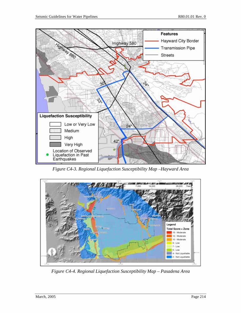
Seismic Guidelines for Water Pipelines R80.01.01 Rev. 0
March, 2005 Page 214
Figure C4-3. Regional Liquefaction Susceptibility Map –Hayward Area
Figure C4-4. Regional Liquefaction Susceptibility Map – Pasadena Area

Seismic Guidelines for Water Pipelines R80.01.01 Rev. 0
March, 2005 Page 215
Figure C4-5. Regional Liquefaction Susceptibility Map – South San Jose Area
For many urbanized areas of the country, liquefaction susceptibility maps have already been prepared; see Power and Holzer (1996) for a detailed bibliography of available liquefaction maps. Ongoing and past consultant studies by firms such as Geomatrix, WLA, Woodward Clyde (now URS) and others have already produced similar maps for the following water utilities or regions:
o San Diego Water Department
o Santa Clara Valley Water District
o East Bay Municipal Utility District
o Greater Memphis Tennessee area
o Greater Salt Lake City area
o Greater Portland Oregon area
o Greater Seattle Washington Area
o Pasadena California

Seismic Guidelines for Water Pipelines R80.01.01 Rev. 0
March, 2005 Page 216
o And many others
Recent "seismic hazard zone" maps prepared by the CGS (formerly CDMG) for purposes of establishing liquefaction special study zones are in general not directly suitable for buried pipe design, in that the CGS liquefaction (and landslide) zones are not defined by the level of hazard, and do not verify that any hazard in fact exists at a particular location (CGS). While these maps could be used as a starting point in developing a liquefaction susceptibility map for pipeline design purposes, the CGS maps should not be used directly as part of the pipeline design approach outlined in these Guidelines.
C4.6.1 Simplified Method to Prepare a Regional Liquefaction Map
A regional liquefaction map should ideally link liquefaction susceptibility categories, such as "very high", "high", etc., with the fragility models used to forecast the level of PGD within these regions, as well as fragility models use to forecast the amount of pipe damage, given the PGD occurs.
The map and associated documentation should provide an estimate of the probability that a specific site will liquefy, and if it does, the amount of permanent ground deformation (PGD) at that site. The PGD can be either vertical (settlement) or lateral (lateral spread) or a combination of the two. If there is a combination, the vector sum value of PGD should be used for use for pipeline design.
Commentary Section C4.6.1 provides a way to establish PGDs given the development of liquefaction hazard maps. These procedures follow the methodology in HAZUS (1997) and have been benchmarked in conjunction with pipe fragility curves (ALA 2001) to give reasonable overall pipe damage patterns from past earthquakes. This process has been used in several large-scale loss estimates for water utilities and has been benchmarked with regards to actual observed pipe damage in past earthquakes. The HAZUS software is based on this model. However good the benchmarking has been done, it is recognized that the process validates only that the cumulative loss through forecast of PGA, PGD and damage due to PGD is verified; and the intermediate steps (PGA, PGD) are only benchmarked against limited empirical observations. No consensus was achieved amongst the authors of these Guidelines (or the wider industry as a whole) regarding easy-and-inexpensive-to-use processes for estimating liquefaction-induced PGD and associated locations of the movement. The absence of an accepted, rigorous procedure for characterizing the spatial variability of liquefaction-induced PGD and the probability of its occurrence requires additional research and development, and is a prime topic for future investigation related to developing a design process for seismic resistant buried water pipelines. With these important caveats in mind, a simplified approach is described in this commentary, as follows.

Seismic Guidelines for Water Pipelines R80.01.01 Rev. 0
March, 2005 Page 217
An assessment of liquefaction susceptibility may be performed using a regional seismic hazard map, similar to those illustrated in Figures C4-3 through C4-5. The assessment should be performed by qualified geotechnical engineers and geoscientists and should incorporate borehole information, water level data, and historical information about the effects of previous earthquakes where such information is available. Areas on the map should be identified and characterized according to liquefaction susceptibility following Table 4-6 and using procedures to deduce liquefaction susceptibility from SPT and CPT data, as described in Chapter 5. From the map, zones designated as having “very high” and “high” susceptibility should be regarded as zones for potential strengthening and protective measures in pipelines either located in or planned for these areas. Using the advice of qualified geotechnical engineers and geoscientists, an estimate of the percentage of each zone designated with “very high susceptibility” and “high susceptibility” that would experience PGD exceeding 1 feet should be made for the 2475-year event. Restrained joints should be used in all new pipelines and pipeline replacements in each zone with “very high” and “high” susceptibility where more that 50% of the zone is predicted to experience PGD 1 feet. The highest priority for strengthening must be given to those pipelines so designated in the “very high susceptibility” zones. The proposed use of regional liquefaction hazard maps acts as a screening process to identify a limited number of pipelines at highest risk from liquefaction effects. The approach promotes seismic protection, and will often result in some measure of strengthening for areas of the US most seriously affected by low frequency, high consequence events. The extent and degree of improvement, however, is constrained within limited geographical bounds to reduce cost and limit the time required for detailed planning and assessment by owner/operator staff.
For practical purposes, most regularly designed (Function I) buried pipelines will sustain damage at PGDs much over a foot; hence extreme accuracy in calculation of the PGD parameter is not essential in these cases.
To proceed with a simplified first order evaluation of a water pipeline, the liquefaction hazard at any location can be calculated in the following steps:
1. For a scenario earthquake (see Section 4.4), calculate the level of shaking (PGA, g) at the particular location of the pipeline to be designed.
2. Establish the geologic unit for the near surface environment at the pipeline location. Table 4-6, after Youd and Perkins (1978) provides a liquefaction susceptibility description for several types of sedimentary deposits.
3. Given the PGA (a, in g), geologic unit and liquefaction susceptibility description, the estimated groundwater depth and the magnitude of the earthquake (using magnitude as a proxy for earthquake duration), calculate the probability that liquefaction occurs at the location, noting that increased magnitude leads to increased chance of liquefaction. A simplified method is provided in equation [C4-

Seismic Guidelines for Water Pipelines R80.01.01 Rev. 0
March, 2005 Page 218
6]. The validity of equation [C4-6] is highly influenced by actual localized soil conditions and groundwater depth, and should not be used without some form of validation for the local soil conditions.
P liquefaction[ ] =P liquefaction PGA = a[ ]
KmKw
Pml [Eq C4-6]
where
P liquefaction PGA = a[ ] = probability of liquefaction given a specified PGA (Table C4 - 3)
Km = the moment magnitude correction factor, equation (C4 - 7)
Kw = the ground water correction factor, equation (C4 - 8)
Pml = the proportion of the map unit susceptible to liquefaction (Table C4 - 4)
Km = 0.0027M 3 0.0267M 2 0.2055M + 2.9188 [Eq C4-7]
Kw = 0.022dw + 0.93 [Eq C4-8]
Note that the liquefaction probability model in equation C4-6 incorporates the same measure of uncertainty as is used to establish PGA=a. In reality, the three other parameters in equation C4-6 (Km, Kw and Pml) are also uncertain; however, the state of the practice in liquefaction modeling usually does not specify uncertainties for these parameters. One possible approach to this limitation is to increase the ground motion attenuation beta (standard deviation of ln a, say from 0.4 to 0.5) for purposes of using this equation; it is left to the expert geotechnical hazard practitioner to quantify this for any specific project.
Liquefaction Susceptibility (From Map or Table 4-7)
P liquefactionPGA = a[ ]
Very High 9.09 a - 0.82 High 7.67 a - 0.92
Moderate 6.67 a - 1.00 Low 5.57 a - 1.18
Very Low 4.16 a - 1.08 None 0.00
Table C4-3. Conditional Probability Relationship for Liquefaction Susceptibility Categories [after Liao et al 1988]
The model in Table C4-3 is based on a moment magnitude 7.5 earthquake and an assumed groundwater depth of five feet. For example, if a = 0.20g and the liquefaction susceptibility description is "High", then the probability of liquefaction in a map unit is 7.67 * 0.20 - 0.92 = 0.614 (61.4%). If the value a=0.20g was at the median level of

Seismic Guidelines for Water Pipelines R80.01.01 Rev. 0
March, 2005 Page 219
motion, then the median chance of liquefaction is 61.4% (using equation C4-6). The equations in Table C4-3 are bounded by 0.0 and 1.0. Equations [C4-7] and [C4-8] are used to adjust the model for different moment magnitudes (Seed and Idriss, 1982) and groundwater depths (dw in feet).
Not all soils within a map unit will have the same liquefaction susceptibility. For liquefaction maps based on wide area geology maps, there will usually be considerable variation of soils within a single mapped soil unit. To approximately account for this spatial variability within a mapped soil unit, Table C4-4 is used. Note that Tables C4-3, C4-4 and C4-5 are linked, and changes in one table could influence the other tables.
Liquefaction Susceptibility (From Map or Table 4-7)
Proportion of mapped unit, Pml
Very High 0.25 High 0.20
Moderate 0.10 Low 0.05
Very Low 0.02 None 0.00
Table C4-4. Proportion of Mapped Unit Susceptible to Liquefaction
4. Given that the site liquefies, calculate the maximum permanent ground
deformation (settlement). Table C4-5 provides a chart to estimate settlements.
Settlement Range Probability Range for Soil Susceptibility (inches) Very High High Low to Moderate
1 0 % 0 % 35 % 1 to 3 5 % 55 % 60 % 3 to 6 25 % 30 % 4 %
6 to 12 50 % 12 % 1 % > 12 20 % 3 % 0 %
Table C4-5. Probable Ground Surface Settlements, Given Liquefaction Occurs
5. If the site is located adjacent to an open cut (often the case when near a body of
water), and the site liquefies, there is a chance that it will also displace sideways (lateral spreading). Equation [C4-9] can be used to estimate the amount of lateral movement.
E PGD[ ] = Kd * E PGD PGA /PGA(t)( ) = x[ ] [Eq C4-9]
where
Kd = 0.0086M 3 0.0914M 2+ 0.4698M 0.9835 [Eq C4-10]

Seismic Guidelines for Water Pipelines R80.01.01 Rev. 0
March, 2005 Page 220
PGA /PGA t( ), = x PGD (inches)
1 to 2 12x - 12 2 to 3 18x - 24 3 to 4 70x - 180
Table C4-6. Lateral Spreading Displacement Relationship [after Youd and Perkins, 1978, Sadigh et al 1986] (for x>4, use x=4)
For example, assume a site with very high liquefaction susceptibility, and PGA = a = 0.36 g, a moment magnitude 7 event, and liquefaction does occur, and site is located adjacent to an open cut or is suitably sloped. Then, the expected lateral PGD would be 78 inches. (PGA(t) = 0.09g from Table C4-7. PGA/PGA(t) = 4. PGD = 70 (4) - 180 = 100 inches, from Table C4-6. Kd = 0.78.
Liquefaction Susceptibility (From Map or Table 4-7)
PGA(t)
Very High 0.09 g High 0.12 g
Moderate 0.15 g Low 0.21 g
Very Low 0.26 g None not applicable
Table C4-7. Threshold Ground Acceleration (PGA(t)) Corresponding to Zero Probability of Liquefaction
The associated range of PGD is assumed to have a uniform probability distribution within bounds of one-half to two-times the displacement calculated using equation (C4-16). For the example given above, the lateral spread displacement would be described as a range between 39 inches to 156 inches.
Additional methods to estimate the effects of liquefaction are provided in the 1997 liquefaction workshop (Youd and Idriss, 1997).
C4.6.2 Buoyancy
Pipe damage to sewer pipes due to buoyancy has been commonly observed in a variety of earthquakes in Japan.
It is felt that practical engineering assessments of pipes can be made by considering the residual strength of the soil.
C4.6.3 Settlement
The simplified approach for settlements using Table C4-5 and equation [C4-6] will result in a range of possible settlements. A conservative design approach for new pipe installation should subsurface information not be available would be to adopt about the

Seismic Guidelines for Water Pipelines R80.01.01 Rev. 0
March, 2005 Page 221
80% non-exceedance level settlements in Table C4-5. For very high susceptible areas, this is 12 inches settlement. For high susceptible areas, this is 6 inches settlement. For moderate susceptible areas, this is 2 inches settlement.
This approach is conservative since the settlements are towards the upper bound, and ignore the fact that large areas within a susceptible zone will not settle at all. Multiplying these settlements (12/6/2 inches) by equation [C4-6] is a reasonable conservative approach when estimating overall system pipe damage estimates.
C4.6.4 Spatial Variation of Liquefaction PGDs
It is ultimately the task of the engineer to select a PGD pattern that reflects the spatial extent of the liquefaction zone, the topography, and the pipeline design approach in order to establish suitable spatial variations of PGD to be considered in pipeline design. A geosciences expert may help define the spatial variation of the PGD for liquefaction, landslide and fault offset for the particular situation at hand.
C4.6.5 Application of Regional Liquefaction Map
The design of water pipelines, especially buried water pipelines, can be largely controlled by the presence of soils subject to permanent ground deformations (PGDs). The PGDs could be from liquefaction, landslide or surface faulting, for example.
It has been the observation of several water utilities that most soils prone to liquefaction-induced PGDs are also highly corrosive. Even after many past earthquakes, it still remains somewhat unclear to what extent observed pipeline damage has been due to PGD, corrosion, or some combination of both. It is likely that there is a high correlation between the two processes.
C4.7 Landslide Assessment The procedure to estimate PGD in the commentary is adopted from HAZUS (1997).
Landslide hazards encompass several distinct types of hazard. There are deep seated and rotational landslides; debris flows; and avalanche / rock falls. These different types of landslides can affect water pipelines in different ways:
o Buried pipelines, valves and vaults. Deep seated rotational and translational landslides pose a significant threat to causing damage to buried pipelines, valves and vaults. Most past efforts in estimating landslide-induced damage to water pipelines has been for deep seated landslides. Debris flows and avalanches are usually not credible threats to buried structures.
Section C4.7 discusses hazard models for deep seated landslide movements. These Guidelines do not present models for debris flows, rock falls or avalanches. If a particular water pipeline appears vulnerable to these types of landslides, then a site specific hazard model should be developed.

Seismic Guidelines for Water Pipelines R80.01.01 Rev. 0
March, 2005 Page 222
There are three basic steps in evaluating the deep seated landslide hazard:
o Develop a landslide susceptibility map.
o Estimate the chance of landslide given an earthquake.
o Given that a landslide occurs, estimate the amount and range of movement.
Landslide Maps. This effort should be performed by geologists familiar with the geology of the area. There are many ways to develop such maps, ranging from aerial photo interpretation to field investigation to borehole evaluations. The cost to develop these maps can be substantial, especially if there are no available maps.
For some areas, landslide susceptibility maps have already been prepared. For example, the USGS has issued a number of such maps (Nielson, 1975). Recent "seismic hazard zone" maps prepared by the CGS for purposes of establishing landslide special study zones are in general not directly suitable for loss estimation, in that the CGS landslide (and liquefaction) zones are not defined by the level of hazard, and not verified that any hazard in fact exists (ref. CGS); while these maps could be used as a starting point in a water pipeline design effort, these maps should not be used with the design procedures presented in these Guidelines. Site specific surveys and aerial photographs can be used for specific pipeline alignments.
Earthquake-induced landsliding of a hillside slope occurs when the static plus inertia forces within the slide mass cause the factor of safety to temporarily drop below 1.0. The value of the peak ground acceleration within the slide mass required to just cause the factor of safety to drop to 1.0 is denoted as the critical or yield acceleration, ac. This value of acceleration is determined based on pseudo-static slope stability analyses and/or empirically based on observations of slope behavior during past earthquakes.
Deformations can be calculated using the approach originally developed by Newmark (1965). The sliding mass is assumed to be a rigid block. Downslope deformations occur during the time periods when the induced PGA within the slide mass, ais exceeds the critical acceleration ac. In general, the smaller the ratio below 1.0, of ac to ais, the greater is the number and duration of times when downslope movement occurs, and thus the greater is the total amount of downslope movement. The amount of downslope movement also depends on the duration or the number of cycles of ground shaking. Since duration and number of cycles increase with earthquake magnitude, deformation tends to increase with increasing magnitude for given values of ac to ais.
The landslide evaluation requires the characterization of the landslide susceptibility of the soil / geologic conditions of a region or subregion. Susceptibility is characterized by the geologic group, slope angle and critical acceleration. The acceleration required to initiate slope movement is a complex function of slope geology, steepness, groundwater conditions, type of landsliding and history of previous slope performance. At the present

Seismic Guidelines for Water Pipelines R80.01.01 Rev. 0
March, 2005 Page 223
time, a generally accepted relationship or simplified methodology for estimating ac has not been developed. The relationship proposed by Wilson and Keefer (1985) is suggested, shown in Figure C4-6. Landslide susceptibility is measured on a scale of I to X, with I being the least susceptible. The site condition is identified using three geologic groups and groundwater level. The description for each geologic group and its associated susceptibility is given in Table C4-8. The groundwater condition is divided into either dry condition (groundwater below level of the sliding) or wet condition (groundwater level at ground surface). The critical acceleration is then estimated for the respective geologic and groundwater conditions and the slope angle. To avoid calculating the occurrence of landsliding for very low or zero slope angles and critical accelerations, lower bounds for slope angles and critical accelerations are established. These bounds are shown in Table C4-9.
Geologic Group Slope Angle, Degrees 0-10 10-15 15-20 20-30 30-40 >40
(a) Dry (groundwater below level of sliding) A Strongly cemented rocks (crystalline
rocks and well-cemented sandstone, (c'=300 psf, =35˚)
None None I II IV VI
B Weakly cemented rocks (sandy soils and poorly-cemented sandstone, (c'=0 psf, =35˚)
None III IV V VI VII
C Argillaceous rocks (shales, clayey soil, existing landslides, poorly compacted fills), (c'=0 psf, =20˚)
V VI VII IX IX IX
(b) Wet (groundwater level at ground surface) A Strongly cemented rocks (crystalline
rocks and well-cemented sandstone, (c'=300 psf, =35˚)
None III VI VII VIII VIII
B Weakly cemented rocks (sandy soils and poorly-cemented sandstone, (c'=0 psf, =35˚)
V VIII IX IX IX X
C Argillaceous rocks (shales, clayey soil, existing landslides, poorly compacted fills), (c'=0 psf, =20˚)
VII IX X X X X
Table C4-8. Landslide Susceptibility of Geologic Groups
Dry
Conditions Wet
Conditions Dry
Conditions Wet
Conditions A 15 10 0.20 0.15 B 10 5 0.15 0.10 C 5 3 0.10 0.05
Table C4-9. Lower Bounds for Slope Angles and Critical Accelerations for Landsliding Susceptibility
The relationships in Figure C4-6 are conservative and represent the most landslide-susceptible geologic types likely to be found in the geologic group. Thus, in using this

Seismic Guidelines for Water Pipelines R80.01.01 Rev. 0
March, 2005 Page 224
relationship, further consideration must be given to evaluating the probability of slope failure, using Tables C4-10 and C4-11.
Table C4-10 provides landslide susceptibilities defined as a function of critical acceleration.
Using the relationship in Figure C4-6 and the lower bound values in Table C4-9, the susceptibility categories are assigned as a function of geologic group, groundwater conditions and slope angle in Table C4-8.
Figure C4-6. Critical Acceleration as a Function of Geologic Group and Slope Angle

Seismic Guidelines for Water Pipelines R80.01.01 Rev. 0
March, 2005 Page 225
Figure C4-7. Relationship Between Displacement Factor and Ratio of Critical
Acceleration and Induced Acceleration
Because of the conservative nature of Figure C4-6, an adjustment must be made to estimate the percentage of a landslide susceptibility category that is expected to be susceptible to landslide. Based on Wieczorek and others (1985), this percentage is estimated using the ratios in Table C4-11, which are presented as a ratio (0.01 = 1%). Thus, at any given location, landsliding either occurs or does not occur within a susceptible deposit depending on whether the peak induced PGA ais exceeds the critical acceleration ac.
For locations which do slide, the amount of PGD can be estimated using equation[C4 -11]. Note that the uncertainty description in equation [C4-11] is governed by the uncertainty in the local induced ground acceleration, aig; however, it is clear from the formulation that there should also be some uncertainty for the other factors in the model; this could be roughly accounted for by increasing the ground motion uncertainty parameter to 0.5 or so; or by having a competent geotechnical engineer provide a site specific description of the uncertainties involved. It is beyond the scope of these Guidelines to assess this pipeline design process.
Susceptibility Category
None I II III IV V VI VII VIII IX X
Map Area None 0.60 0.50 0.40 0.35 0.30 0.25 0.20 0.15 010 0.05
Table C4-10. Critical Accelerations (ac) for Susceptible Categories
Susceptibility Category
None I II III IV V VI VII VIII IX X
Map Area 0.00 0.01 0.02 0.03 0.05 0.08 0.10 0.15 0.20 0.25 0.30
Table C4-11. Percentage of Map Area with Landslide Susceptible Deposit

Seismic Guidelines for Water Pipelines R80.01.01 Rev. 0
March, 2005 Page 226
E PGD[ ] = E d /ais[ ]aisn
where
E d /ais[ ] = the expected displacement per cycle, Figure C4 - 7
ais = the induced acceleration (in g)
n = the expected number of cycles, equation [C4 -12].
[Eq C4-11]
The relationship between the number of cycles and moment magnitude is estimated using equation [C4-12], which is based on Seed and Idriss (1982).
n = 0.3419M 3 5.5214M 2+ 33.6154M 70.7692 [Eq C4-12]
For relatively shallow and laterally small landslides, ais is not significantly different from the induced PGA at the surface of the slide, ai. For deep and large slide masses, ais is less than ai. For many applications, it may be reasonable to assume ais = ai. However, soil column deamplification and topographic amplification effects may be important in some cases. The uncertainty in any estimated landslide PGD is governed by the uncertainty in the local induced ground acceleration, and for other factors in the model; this could be roughly accounted for by using a suitable ground motion uncertainty parameter (perhaps 0.5 or so); or by having a competent geotechnical engineer provide a site specific description of the uncertainties involved. It is beyond the scope of this document to assess this uncertainty, other than to note that this value may be important in terms of the overall water pipeline design process.
C4.8 Ground Motion Parameters in Other Codes The maps and procedures listed in the Guidelines to establish site-specific PGA and PGV values rely on country-wide maps and simplistic conversion tables to consider site-specific soil conditions.
2003 International Building Code
• Ground motion parameters based on 2% chance of exceedance in 50 years (=2,475 year recurrence interval).
• 5% damped response spectra are developed from the spectral acceleration at short periods (Ss) [determined at 0.2 second period] and at 1 second period (S1). Ss and S1 are determined from maps plotted for these parameters for all US states and territories for B/C rock sites.
• The site specific design parameters at short periods and 1 second period SMS and SM1, respectively, are determined from:
o SMS = FaSs o SM1 = FvSs o Fa and Fv are site coefficients that define the spectral shape as a function of
site conditions that differ from B rock sites.

Seismic Guidelines for Water Pipelines R80.01.01 Rev. 0
March, 2005 Page 227
• The design spectral response is determined from: o SDS = (2/3)SMS o SD1 = (2/3)SM1 o Note: These Guidelines do not provide this 2/3 factor. The 2/3 factor
should not be used for the seismic design of water pipelines. • The peak ground acceleration (zero period acceleration) is determined from
0.4SDS • This recurrence interval chosen because the common 475 year recurrence interval
used for West Coast seismic design in the UBC is considered to provide such low level ground motions for Midwest and Eastern regions of the United States as to result in seismic design that would not provide any real safety should a large earthquake (2% in 50 year) occur. Therefore the IBC adopted the 2,475 year return period and scaled it down to be similar (with a fudge factor of 2/3 which rarely works accurately) to the 475 year return period in high-seismic California. This effectively normalizes ground motion parameters to be inconsistent with regards to risk across the entire USA.
ASCE 7.02
• Same as IBC 2000.
1997 NEHRP Provisions
• Same as IBC 2000. IBC used same methods as presented by 1997 NEHRP.
UBC 1997
• Ground motion parameters based on 10% chance of exceedance in 50 years. 475 year recurrence interval.
• Site seismic hazard characteristics are established based on the seismic zone, site proximity to active seismic sources, site soil profile characteristics, and the facility importance.
• The seismic zone factor Z is determined from a map identifying regions of different shaking hazard for zones 1, 2a, 2b, 3, or 4. Z = 0.075 to 0.4.
• For Zone 4, each site is assigned a near source factor Na based on the seismic source type. These near source factors are eliminated in most subsequent codes that are based on PSHA.
• Seismic coefficients Ca and Cv are assigned for each site based on the seismic zone and soil profile.
• Peak ground acceleration represented by Ca. • Code specifies method for generating response spectra. • Comparison with IBC:
o Spectral shapes are developed the same. o Ca = 0.4SDS o Cv = SD1

Seismic Guidelines for Water Pipelines R80.01.01 Rev. 0
March, 2005 Page 228
JWWA
• Design for two different magnitudes of intensity o Strong Motion Level 1, L1, has a return probability of once or twice in the
service life of the facility • Similar to standard motions for civil design.
• Strong Motion Level 2, L2, has a smaller probability than L1 and is greater in magnitude.
o Motion generated in areas with faults or large scale plate boundaries bordering inland areas
o Design basis is the 1995 Hyogoken Nanbu (Kobe) Earthquake. o If fault or plate boundary cannot be clearly defined then must design for
L2. • See JWWA pages 16 to 32 for descriptions of ground motion
parameter evaluations. Pages 28 to 32 cover peak ground motions and site natural periods.
C5.0 Subsurface Investigations Table 5-1 provides guidance as to the type of information that is recommended for general and seismic pipeline design.
We have ranked the subsurface information to be collected in accordance with the pipe Function Class.
For Function Class II, we rely mostly on regional geologic information. With this information, plus the probabilistic PGD models in the Commentary, a rational approach can be taken to seismically design most distribution pipelines.
For Function Class III and IV, we suggest subsurface investigations. If a geoscience expert with knowledge of local soil conditions suggests that there are no liquefaction, landslide or faulting conditions along the pipeline alignment, then the subsurface program can be pared down to the minimum needed to provide the pipeline contractor with sufficient information to price the installation effort. The subsurface information in Table 5-1 would be useful at locations known (or suspected) prone to fault offset, lateral spread, landslide or substantial settlement.
C6.0 General Pipeline Design Approach It is beyond the scope of these Guidelines to provide a complete treatment of the non-seismic design of buried water pipelines. Instead, we provide outlines of some of the main loading parameters that are commonly considered in non-seismic design. Moser (2001) provides a 600+ age book on the design of buried pipe. However, Moser (2001) only casually mentions that earthquake loading.

Seismic Guidelines for Water Pipelines R80.01.01 Rev. 0
March, 2005 Page 229
These Guidelines make no suggestion of how to combine seismic load cases with other load cases. Generally, the seismic load case leads to stresses in the pipe along the longitudinal axis of the pipe, and the most other load cases lead to stresses in the hoop (pressure) or through wall (external soil load) directions. Thermal loads are usually self-relieving, so need not usually be combined with seismic loads. Hydrostatic thrust and hydrodynamic thrust loads should be considered in conjunction with seismic loads.
For purposes of these Guidelines, seismic loads can be combined with other loads, where applicable, using unit load factors.
C6.6 Fluid Transients Throughout these Guidelines, we make little mention of the effects of water within the pipeline on overall pipeline response. For buried pipes, this seems to be mostly true if considering just the effects of filled-pipe-soil interaction. However, there is continuing debate as to whether the forces due to pressure in the pipe are somehow increased during the earthquake, in part due to surge transients.
For above ground pipes, it is required to always include the mass of the water within the pipe as part of overall inertial loading for transverse and vertical loading. If the pipe bends are spaced closer than about 100 pipe diameters, it is rational to include the entire mass of water in the longitudinal as part of the dynamic analyses, when forecasting forces on adjacent bends in the pipe.
For above ground pipes that are straight for very long distances, such as many thousands of feet, it is too conservative to apply the entire mass of water as a constant inertial load to the bends at the ends of the straight run. As the pipe accelerates along the straight length, the bend at the end of the straight run will impose some dynamic impulses to the water, akin, in a way, to a valve closing transient, albeit with much shorter application time. It would be too conservative to apply this imposed loading to the water over the entire length of long straight pipe.
C7.0 Analytical Models Nothing in these Guidelines should be taken as a recommendation to install one kind of pipe over another, as long as a rational analysis can show that the installed pipe will meet the intended performance.
C7.1 Three Models, and When to Use Them In some other reports, the Finite Element Method is sometimes called a "dynamic analysis method". But for buried pipelines there are rarely any pipe mass or velocity terms important to pipeline response, as the pipe usually moves more-or-less with the soil and the pipe itself rarely has any dynamic amplification; thus we avoid the term "dynamic analysis method" in this report. This statement does not apply to hydrodynamic forces of the water within the pipe.

Seismic Guidelines for Water Pipelines R80.01.01 Rev. 0
March, 2005 Page 230
In most cases when using the Finite Element Method, it will be sufficient to just apply PGDs to the pipeline. PGA and/or PGV application could be applied for sections of pipe through long vaults, on bridges or where inertial response might be important.
A pipe designed by the finite element method will often be shown on contract drawings showing material selection, joint preparation, trench design and other factors. An engineer's certified stress report may accompany an important pipeline designed by the finite element method.
C7.2 Chart Method Due to the inherent assumptions in the Chart Method, the reliability / factor of safety / margin of the pipeline will not be quantified. Note that the ESM or FEM methods can be used at any time, and designs using the ESM or FEM methods will be more quantified than those based on the Chart Method. If there is a conflict between the Chart and the ESM or FEM methods, the method which provides the most confidence in meeting the overall performance goals should be relied upon. The ESM method will, in general, provide more confidence than the Chart method. The FEM method will, in general, provide more confidence than the ESM method.
Tables 7-1 through 7-19 provide a simple classification system for pipelines versus the level of seismic PGV and PGD hazards. Once the PGV and PGD is estimated for particular pipeline location, then the designer uses the following tables to indicate the desired style of pipeline design. Note: the ESM or FEM methods can be used at any time, and the selections using those methods will always supersede the selection based on the chart method.
Table 7-3 deals with PGDs along the length (parallel) to the pipeline. These have been shown to cause more damage to pipelines than PGDs transverse to the pipeline, given an equal amount of PGD. Type E design is the same as Type D design, except with peer review.
C7.2.1 Design Approach
Tables 7-11 through 7-19 describe what the Guidelines mean for each design category. The end user can adjust these design categories by verifying (by test, ESM or FEM) that show that the seismic performance for a particular style of pipeline installation will meet the overall system-wide intended performance goals.
Tables 7-11 and 7-12 suggest that ductile iron pipe can be used for classifications D and E, whereas PVC cannot. It should be pointed out that PVC likely has superior corrosion resistance than ductile iron pipe, and this might be a trade-off for pipe selection. With suitable design, PVC pipe could be made able to tolerate large PGDs, by a combination of suitable joint restraint devices, shortness of pipe barrel length, etc. Nothing in these Guidelines should be taken as a recommendation to install one kind of pipe over another,
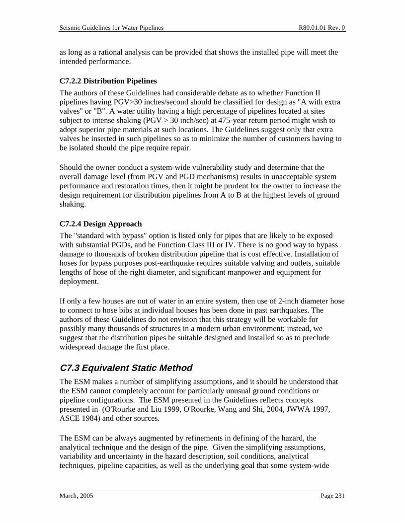
Seismic Guidelines for Water Pipelines R80.01.01 Rev. 0
March, 2005 Page 231
as long as a rational analysis can be provided that shows the installed pipe will meet the intended performance.
C7.2.2 Distribution Pipelines
The authors of these Guidelines had considerable debate as to whether Function II pipelines having PGV>30 inches/second should be classified for design as "A with extra valves" or "B". A water utility having a high percentage of pipelines located at sites subject to intense shaking (PGV > 30 inch/sec) at 475-year return period might wish to adopt superior pipe materials at such locations. The Guidelines suggest only that extra valves be inserted in such pipelines so as to minimize the number of customers having to be isolated should the pipe require repair.
Should the owner conduct a system-wide vulnerability study and determine that the overall damage level (from PGV and PGD mechanisms) results in unacceptable system performance and restoration times, then it might be prudent for the owner to increase the design requirement for distribution pipelines from A to B at the highest levels of ground shaking.
C7.2.4 Design Approach
The "standard with bypass" option is listed only for pipes that are likely to be exposed with substantial PGDs, and be Function Class III or IV. There is no good way to bypass damage to thousands of broken distribution pipeline that is cost effective. Installation of hoses for bypass purposes post-earthquake requires suitable valving and outlets, suitable lengths of hose of the right diameter, and significant manpower and equipment for deployment.
If only a few houses are out of water in an entire system, then use of 2-inch diameter hose to connect to hose bibs at individual houses has been done in past earthquakes. The authors of these Guidelines do not envision that this strategy will be workable for possibly many thousands of structures in a modern urban environment; instead, we suggest that the distribution pipes be suitable designed and installed so as to preclude widespread damage the first place.
C7.3 Equivalent Static Method The ESM makes a number of simplifying assumptions, and it should be understood that the ESM cannot completely account for particularly unusual ground conditions or pipeline configurations. The ESM presented in the Guidelines reflects concepts presented in (O'Rourke and Liu 1999, O'Rourke, Wang and Shi, 2004, JWWA 1997, ASCE 1984) and other sources.
The ESM can be always augmented by refinements in defining of the hazard, the analytical technique and the design of the pipe. Given the simplifying assumptions, variability and uncertainty in the hazard description, soil conditions, analytical techniques, pipeline capacities, as well as the underlying goal that some system-wide

Seismic Guidelines for Water Pipelines R80.01.01 Rev. 0
March, 2005 Page 232
damage is acceptable, refinement in the ESM may (or may not) not be warranted. For important pipelines (Function Class III and IV) and where the PGD hazard is well characterized (total displacement and deformation pattern), consideration should be given to use of the Finite Element Method.
As of 2005, quantified strengths and displacement capacities of pipes and pipe joints are not usually included in pipe manufacturer's catalogs. Pipeline designers need such information to make informed decisions as to pipe selection for particular installations. One approach that a designer can take is to put the required pipeline forces and displacement capacities into a specification, and allow the pipeline vendor to supply that information as part of the procurement process.
C7.3.1 Analysis for Ground Shaking Hazard
In practice the most energetic seismic waves in common soil conditions are shear (body) waves, and these can propagate at speeds of c= 12,000 to 20,000 feet per second. In uncommon cases, less energetic Rayleigh (surface) waves can propagate at slower speeds.
There is open question as to the actual energy of body and surface waves and their propagation speeds; however there is strong evidence that wave propagation (PGV) loading without concurrent PGD loading causes just limited or modest damage to buried water pipe networks; at least in past earthquakes in coastal California.
To simplify these Guidelines, we just assume c = 13,000 feet / second as a safe design approach in most instances. The user can always perform site-specific studies to refine this assumption for sites with special characteristics.
The pipe barrel should be designed to remain elastic (such as for steel and ductile iron pipe) for ground shaking. For materials where yield level is not applicable, the design for the pipe barrel should have very high reliability against failure under the 475-year ground shaking motion. For metal pipes, pipe barrel yielding due to ground shaking should be avoided unless the underlying system-wide performance goal is assured.
Continuous Pipe
For continuous pipe, the seismic ground strain is accommodated by alternating axial tension and axial compression in the pipe. If the wave length of the seismic excitation, , is long and the soil is strong (large ultimate force per unit length at the soil pipe interface, tu) the axial strain in the pipe is about equal to the ground strain. Hence, the axial force in the pipe is the ground strain times the pipe axial rigidity and the peak force is computed as F1. On the other hand, if is short and/or tu is small, the axial strain in the pipe will be much less than the ground strain. The maximum force in the buried pipe is tu times a quarter wavelength "development length". This is the peak force F2. For example, given that PGV = 50 cm/sec and c = 13,000 ft/sec. Then:

Seismic Guidelines for Water Pipelines R80.01.01 Rev. 0
March, 2005 Page 233
pipe =50
13,000x12x2.54
cm /sec
( ft /sec)* (in / ft) * (cm /in)= 0.000126
For a continuous pipe, (like double lap welded steel pipe), then the peak seismic stress along a long straight length of pipe is (but not at the joint):
pipe = pipe E = 0.000126*29000ksi = 3.7 ksi
This modest level of axial stress in the pipe due to ground shaking is much less than the nominal yield stress of steel (depending upon grade, 30 ksi or higher). This example demonstrates that even moderate to strong levels of ground shaking should not cause much, if any, damage to continuous welded steel water pipelines, even if they use just single lap welded joints.
Assume a 43 inch outside diameter steel pipe with wall thickness of 0.50 inches. The pipe axial area is about:
A = Dt = 3.14 * 42.5*0.50 = 66.7 sq. inches
Assuming the pipe does not slip through the soil, the peak pipe axial (tension or compression) force is then:
F1 = 66.7*29000*0.000126 = 244 kips
For the example pipe buried with in medium stiff clay, and assuming a typical concrete coating system, then tu (see Section 7.4 for details on calculating tu) is about 938 pounds per inch.
kipsF 300,184
12*500,6*938.0
2==
The recommended design force for this example is therefore 244 kips.
Continuous Pipeline with One Unrestrained Joint
This model in Figure 7-3 can be used for a long welded steel pipeline with a single dresser coupling (say near a valve), in order to size up the required expansion movement at the coupling. For example, say A = 170 square inches, E = 29,000 ksi, tu = 0.89 kip/inch, V = 32 inches/second, c = 2000 ft/sec (assumes very soft soil conditions), = 2000 feet (assumes long period motions). Then T = 1 second, o =10.2 inches, R =
4Vc = 2.22e 7 and tu
EAR = 0.81 and 0
0.5 ; so 0.5*10.2 = 5.1 inches.

Seismic Guidelines for Water Pipelines R80.01.01 Rev. 0
March, 2005 Page 234
This simplified model ignores water thrust forces. All pipe should be designed to accommodate hydrostatic and hydrodynamic water thrust forces in addition to any forces or movements needed to accommodate strains from ground shaking or permanent ground deformations.
C7.3.2 Analysis for Landslide and Liquefaction Hazard
For landslides and liquefaction, the hazard is characterized as being either longitudinal (pipe axis more or less parallel to the direction of permanent ground movement), or transverse (pipe axis more or less perpendicular to the direction of permanent ground movement). Buried Pipe Response to Longitudinal PGD There are a number of different ground displacement patterns for longitudinal PGD. The relationship in these Guidelines is based upon a uniform block pattern (Figure C7-1). In a block pattern, a mass of soil having length Ls, moves a distance down-slope (or towards a free face). Procedures for establishing expected values for both the length of the soil block LS, as well as the amount of ground movement are presented in Sections 4.3 and 4.4. In lieu of specific knowledge about the particular site, the values in Table C7-1 are suggested. The recommended value for Function Class II is taken as the median of the observed data for actual lateral spreads, while the values for Function Class III, and IV correspond approximately to the 70 and 90 percentiles respectively.
F1 is based on the following assumptions for an elastic pipe.
Figure C7-1. Idealized Lateral Spread
The total displacement to be absorbed by the pipe between the two end points is , or 2
on each side of the spread, and the spread extends for a length Ls on each side of the ground crack in Figure C7-1. Then:

Seismic Guidelines for Water Pipelines R80.01.01 Rev. 0
March, 2005 Page 235
2= pdx
0
L=
tux
AE0
L
=tuL
2
2AE
L =AE
tu
F1 = Ltu = AEtu
The user should recognize that the displacements in Table C7.1 are scenario displacements, meaning that they assume the site will liquefy and will have a lateral spread (or, the landslide will move). In practice only a percentage (often between 5% and 50%) of an area that is mapped as having high to very high liquefaction (or landslide) susceptibility actually will liquefy and move in a lateral spread, given a large earthquake with sufficiently high acceleration and sufficiently long duration so as to analytically predict that liquefaction might occur. Therefore, for design purposes for a complete distribution network, when relying upon incomplete subsurface information, the Chart Method (which already incorporates probability that the hazard occurs) might provide a first-order solution; or if using the ESM, some factor should be considered to consider the probability of lateral spread on an individual pipe and design accordingly. If the ESM approach is used, and if the subsurface information is largely unknown (except that the pipe is located in an area with high to very high liquefaction/landslide susceptibility), then a rational design might be to multiply the scenario-based spreads (listed in Table C7-1) by about 0.20 (or Pml per Table C4-4) and then design using that displacement. For Function Class III and IV pipes, their importance would suggest that suitable geotechnical investigations be performed, and using the scenario-based design motions is appropriate.
Function Class LS (ft) (ft) II 300 6 III 500 9 IV 700 15
Table C7.1 Recommended Values for the Length of the Longitudinal PGD Zone, LS, and the
Amount of Ground Movement Continuous Pipe. Longitudinal PGD results in areas of axial tension and axial compression in continuous buried pipe. If the length of the block LS is relatively large, there are separate regions of axial tension near the head of the slide and axial compression near the toe. Between these regions, that is near the center of the block the axial stress in the pipe is zero and there pipe displacements match that of the ground. For elastic pipe it can be shown that the peak force (tension at the head and compression at the toe) needed to cause the pipe to stretch a displacement, is F1.
If the length of the block is relatively small, the regions of axial tension and axial compression will abut each other, and the pipe displacement at the center of the block

Seismic Guidelines for Water Pipelines R80.01.01 Rev. 0
March, 2005 Page 236
will be less than . For this case, the peak axial force in the pipe (tension at the head, compression at the toe) is due to the soil friction force is F2. When LS is relatively small, the length of the block controls, and F2 gives the peak force in the pipe, and F1 overestimates the peak force. Conversely, when LS is large, the amount of ground movement controls, F1 gives the peak force in the pipe, while F2 overestimates the peak force. Hence, it is appropriate to use the smaller value of F1 or F2 as the design force. Segmented Pipe. Longitudinal PGD results in axial expansion and contraction at the joints of a segmented pipeline. For a block pattern, joints in the immediate vicinity of the head and toe must accommodate the PGD movement . For pipe systems with unrestrained joints, it is assumed that the ground movement is accommodated by expansion of a single joint at the head and by contraction of a single joint at the toe.
For pipe systems with restrained joints (chained joints = the joint can slip somewhat, and then a restrained stop restricts further movement), it is assumed that (n + 1) pipe segments and n restrained joints at both the head and toe of the longitudinal PGD zone
accommodate the ground movement . Hence each restrained joint must allow n
worth of expansion at the head or n
worth of contraction at the toe. In order for a
restrained joint to “share” and “distribute” the imposed ground movement, it must be able to transmit axial force in its fully expanded or fully compressed state. For n restrained joints near both the head and toe regions, the axial force in the joint increases as one moves closer to the head and toe, respectively. The axial force in the joint closest to the head and toe is Fstop.
A factor of safety of 2 is suggested for design of the stop in tension, recognizing that the stop might weaken over its lifetime (corrosion), there may be installation defects, etc; if the designed can demonstrate otherwise, the factor of safety can be reduced to 1.25. The stop need not be stronger than the actual yield of the barrel in tension.
In compression, the stop mechanism of a chained joint might be the male spigot bearing against the female end, such as for ductile iron pipe. For PVC pipe, there may be no "stop" in that the male spigot might be able to squeeze into the adjacent pipe barrel; in such a case, it would be good to confirm that adjacent barrel does not split.
Buried Pipe Response to Transverse PGD Equations [7-14, 7-15, 7-16] in the Guidelines are based upon a sinusoidal pattern of ground displacement (y(x)) across the PGD zone, that is
( )2 x
y x 1 cos2 W
=

Seismic Guidelines for Water Pipelines R80.01.01 Rev. 0
March, 2005 Page 237
where, W is the width of PGD zone and is the amount of transverse movement towards the center of the zone.
Procedures for establishing expected values for both the width W of the zone for transverse PGD, as well as the amount of ground zone movement are presented in Sections 4.3 and 4.4. The scenario values in Table C7-2 are suggested if the hazard is confirmed by suitable investigation; probabilistic values can be used if the hazard is only roughly defined in terms of its location and likelihood of movement at the 475-, 975- or 2,475-year return period motions. The recommended value for Function Class II is taken as the median of the observed data, while the values for Function Class III and IV correspond approximately to the 70 and 90 non-exceedance percentiles, respectively. Note that for transverse PGD, the hazard is more severe for pipes for smaller values of W.
The user should recognize that the displacements in Table C7.2 are scenario displacements, meaning that they assume the site will liquefy and will have a lateral spread (or, the landslide will move). In practice only a percentage (often between 5% and 50%) of an area that is mapped as having high to very high liquefaction (or landslide) susceptibility actually will liquefy and move in a lateral spread, given a large earthquake with sufficiently high acceleration and sufficiently long duration so as to analytically predict that liquefaction might occur. Therefore, for design purposes for a complete distribution network, when relying upon incomplete subsurface information, the Chart Method (which already incorporates probability that the hazard occurs) might provide a first-order solution; or if using the ESM, some factor should be considered to consider the probability of lateral spread on an individual pipe and design accordingly. If the ESM approach is used, and the subsurface information is largely unknown (except that the pipe is located in an area with high to very high liquefaction/landslide susceptibility), then a rational design might be to multiply the scenario-based lateral displacements (listed in Table C7-2) by about 0.20 and then design using that displacement. For Function Class III and IV pipes, their importance would suggest that suitable geotechnical investigations be performed, and using scenario-based design motions is appropriate.
Function Class W (ft) (ft) II 900 6 III 700 9 IV 500 15
Table C7-2 Recommended Scenario Values for the Width of the Transverse PGD Zone, W, and
the Amount of Ground Movement . (Lateral Displacement) Transverse displacements due to liquefaction-induced settlement can be based on Table C4-5; these will be much less than those in Table C7-2 (spread). The approach in Section C4.6.1 can be used to establish the value in lieu of Tables C7-1 and C7-2 for purposes of lateral spread.

Seismic Guidelines for Water Pipelines R80.01.01 Rev. 0
March, 2005 Page 238
Continuous Pipe. A continuous buried pipe subject to distributed transverse PGD will tend to follow the soil displacement by bending in the horizontal plane; some pipe slippage will usually occur. For the sinusoidal pattern assumed, ground movement results in negative bending moments at the margins of the zone, and positive moment at the center of the zone. In terms of its flexural behavior, the pipe behaves like a fixed-fixed beam subject to a transverse load. In equation [7-14], it is assumed that the pipe follows the ground displacement exactly. In equation [7-15], it is assumed that the pipe acts like a beam carrying the load. Since both are limiting conditions, the prescribed strain is the smaller.
Segmented Pipe. For segmented pipeline systems with unrestrained joints, transverse PGD is accommodated primarily by a combination of axial expansion and angular rotation at the joints. The joint axial expansion arises from arc length effects. That is the total length along the deflected pipeline is larger than that for the originally straight pipe. The joint angular rotation results from the nominally rigid (EI = ) pipe segments mimicking the transverse ground displacement. The peak axial expansion due to arc length effects occurs at different points than the peak angular rotation. The maximum joint openings due to the combined axial and rotational effects are described by the equations in the Guidelines are adopted from O’Rourke and Nordberg (1991).

Seismic Guidelines for Water Pipelines R80.01.01 Rev. 0
March, 2005 Page 239
Segmented Buried Alternate Method
The ESM method to design pipelines to accommodate liquefaction-induced PGDs relies on assumptions about the general nature of PGDs in liquefaction zones. During the 1995 Hyogo-ken Nanbu (Kobe) earthquake in Japan, large amounts of liquefied ground moved towards the sea (downslope) when retaining walls at the ground/sea interface failed and rotated towards the sea. The movement was a lateral spread. The spreading caused significant damage to buried water pipelines.
The recommended approach is as follows.
First, determine the liquefaction susceptibility of the area where the pipe will traverse. Regional maps such as that shown in Figure C4-3 are a good source. Maps such as these are available on-line (http://www.abag.ca.gov/bayarea/eqmaps/liquefac/liquefac.html) and USGS in GIS format, and can be expanded to show particular city streets.
For areas mapped as having "high" or "very high" liquefaction susceptibility, assume that a percentage of such mapped areas will liquefy in earthquakes with M 6.5 of higher, when the fault is within 20 km of the site. The percentage of land that will liquefy will depend on local soil subsurface conditions, ground water table, etc. In the ESM method, developing such detail is not required. Instead, the following simplifying assumptions are made:
• At locations that do liquefy, and are located within 1,000 feet of a water boundary (bay front or creek) or on land with average slope more than 1%, the resulting ground strain, g , in the downslope (toward the water) horizontal direction will
typically range from 0.5% to 1.0% (60% of locations) and up to 2.0% (90% of locations). The suggested design value of 1.5% is a reasonable estimate of high (but not highest) ground strain.
• At locations that do liquefy, and are located more than 1,000 feet from of a water boundary (bay front or creek) or on land with average slope from 0% to 1%, the resulting ground strain, g , in any horizontal direction will typically range from
0.5% to 1.0% (75% of locations) and up to 1.5% (90% of locations). The suggested design value of 0.75% is a reasonable estimate of high (but not highest) ground strain.
For example, at a relative flat location more than 1,000 feet from a shoreline, for a pipe with lay length of 12 feet, the pipe joint movement is predicted to be 0.0075 * 12 feet * 12 in/ft = 1.08 inches at the joint. This alternate method requires chained segmented pipe with designed stops or continuous pipe with suitable joints.
Just because the map in Figure 4-1 shows an area as having high or very liquefaction susceptibility does not mean that it will actually liquefy, even in large magnitude earthquakes. If the designer wishes to do careful subsurface investigation for the pipeline

Seismic Guidelines for Water Pipelines R80.01.01 Rev. 0
March, 2005 Page 240
alignment, and finds soil layers susceptible to liquefaction, then more accurate and refined designs can be accomplished. However, this level of detail will not often be employed for small diameter distribution pipelines, and probably never for service laterals.
As a compromise between level of analysis / subsurface investigation and cost, we suggest the following approach for segmented pipe:
• Select Function Class
• Estimate the PGD. The PGD varies based on Function Class.
• design = joint + operational + 0.25 inch
C7.3.3 Fault Crossing Ground Displacement Hazard
Fault crossing is arguably one of the most severe hazards for buried pipe. The horizontal and vertical offsets can be large (2 to 3 feet for magnitude 6 to 6.5 earthquakes, and 10 feet or much more for M 7.5 and larger earthquakes), and occur over relatively narrow fault zone. The relations presented in the guidelines are based on the conservative assumption that the offset occurs across a single line (i.e. “knife edge” fault). Hence, the hazard is simply characterized by the offset . Procedures for establishing appropriate values for are presented in Section 4.5.
Continuous Pipe The Newmark - Hall (1975) closed form method to estimate pipe strain due to fault offset has been shown by finite element, empirical and test methods to ignore an important failure mechanism, that is, the localized bending and possible wrinkling in a continuous pipeline within 20 to 50 feet either side of a fault offset. As the formula, equation [7-18] without the first "2", is very easy to use, only requiring estimates of tu, La and the amount of fault offset , it is retained in these Guidelines, but increased by a factor of 2. This is not to say that we endorse the method or its findings for other than a quick estimate of pipe strain for a given amount of fault offset. For important pipelines, this method should only be used for initial sizing purposes; and the FEM method should be use to design validate the pipe. Further, it is recommended that this formulation only be used if the pipe is subject to net tension, as the formulation ignores "p-delta" type effects when the pipe is subject to net compression.
A steel pipe with double lap welds can be used to accommodate fault offset. The double lap welds invoke a stress and strain riser, such that the girth joint will begin to wrinkle at about 90% of nominal yield in the main pipe (if in compression) or accumulate peak strain much faster than the main body of the pipe (if in tension). In tension, a common double lap welded joint might fail one-third of the time when the main body of the pipe has reached 8% strain (due to welding flaws and geometric intensification).

Seismic Guidelines for Water Pipelines R80.01.01 Rev. 0
March, 2005 Page 241
Segmented Pipe For segmented pipeline systems with unrestrained joints, the fault offset is accommodated by axial expansion/contraction and angular rotation at the joints in combination with bending at the pipe segments between the joints. The relation presented in the Guidelines assume that the two joints closest to the line of rupture (one on each side of the fault) accommodate all the offset. That is, it is assumed that the joints are incapable of transmitting axial tension, axial compression or bending moments.
The fault offset can be decomposed into a longitudinal component cos , parallel to the pipeline axis and a transverse component sin , normal to the pipeline axis. The relations in the Guidelines for the required axial extension/contraction capability are based upon the assumption that the longitudinal component is shared equally by the pair of joints, each side of the fault line. The Guideline relations also assume that the transverse component of fault offset is accommodated by angular rotation of the same pair of joints. The pipe segment that crosses the fault rupture line is subject to shearing forces from soil pushing in one direction on one side of the fault, and pushing in the opposite direction on the other. The relations in the Guidelines for moment and shear are based on the assumption that the center of the pipe segment is located directly over the fault.
As a matter of practicality, segmented (unchained) pipe will likely fail when subject to fault offset much over a few inches to at most a couple of feet. Suggested design is a continuous pipeline with joints capable of sustaining considerable yielding; pipe bodies that are not subject to much (if any) wrinkling; or, possibly in lesser important pipelines, chained joints.
C7.4.1 Pipe Modeling Guidelines
The effects of internal pressure (up to about 150 psi, typical for water pipelines) on the behavior of pipes to withstand PGDs such as fault offset has generally been shown to have the following impacts:
• Internal pressure will tend to lower the axial forces needed to initiate wrinkling
• Internal pressure will tend to increase the capability of the pipe to withstand extended wrinkling once it has occurred.
• Internal pressure will have negligible effect on total pipeline response when hoop stress caused by internal pressure is less than about 25% of the yield stress.
For regular steels (such as SA106 Grade B, A-53, A36, X42), the pipe material law might be described in a three-way piece-wise linear manner (a tri-linear stress-strain behavior): linear stress-strain relation up to nominal yield; then a reduced tangent modulus up to nominal allowable strain; and then a further reduced tangent modulus up to ultimate uniform strain.

Seismic Guidelines for Water Pipelines R80.01.01 Rev. 0
March, 2005 Page 242
Practitioners in the oil and gas industry suggest that pipe elements need not be shorter than one pipe diameter near locations of high bending in the pipe. For very large diameter water pipes (like 8 feet diameter), this discretization may be too large to capture the rapid changes in curvature near fault offset locations.
C7.4.2 Soil Modeling Guidelines
In most cases, soils can be modeled as bilinear load-deflection curves to capture the pipe-sol response.
Soil spring properties (stiffness, strength) should be varied to considered the likely range of field conditions, in order to get the upper bound /lower bound loads on the pipe and nearby appurtenances. Stiffer and stronger soils will usually result in higher pipe response (higher strains) at the PGD offset; but lower loading on the pipe away from the PGD offset; the opposite occurs for less stiff and weaker soils.
The soil strength descriptions in Figures 7-6 through 7-11 are also included in ALA (2001), presented by formulae instead of charts.
C7.4.3 Wrinkling
The "wrinkling strain" is usually reported in the literature as the strain in the main barrel of the pipe at a distance away from the wrinkle. In fact, once the pipe starts to wrinkle, the actual strains in the wrinkle will be much higher than those in the main barrel of the pipe away from the joint. Equations [7-31 and 7-32] provide allowable strains in the main barrel of the pipe away from the wrinkle. Equation [7-31] (without the 0.75 reduction factor) assumes the D/t ratio is less than 120 (Gresnigt, 1986) and is based on the strain at maximum moment capacity at the wrinkling. If a complete nonlinear analysis of the pipe is done, then a suitable spring/finite element formulation of the wrinkle should show unloading in the main barrel of the pipe away from the wrinkle, while strain builds up rapidly within the wrinkle, as PGD is increased. Simpler beam-on-inelastic-foundation type models will not capture this effect. In cases where the wrinkle is actually modeled, the strain allowable within the wrinkle is higher than those inferred by equations 7-31 and 7-32. Depending on application, the allowable strain within the wrinkle could be as low as 5% (high confidence that the pipe will not leak) to as high as 20% (likely that the pipe will split open). It is left to the user to define a suitable strain within the wrinkle that matches the target performance for the pipe, should the acceptance criteria be based on strain within the wrinkle.
The Thames Water Pipeline (2.2m diameter butt welded steel pipe) underwent 3 m of right lateral offset in the August 17, 1999 earthquake on the Anatolian fault. Post-earthquake analyses of the pipeline (Eidinger 2001, Eidinger, O'Rourke, Bachhuber 2002). The pipe crossed the fault such that substantial compression and bending occurred in the pipe, and the pipe wrinkled. Figure C7-2 shows one of the wrinkles, as seen from inside the pipe. While the pipe leaked at one of the wrinkles, it remained in service for several days after the earthquake.

Seismic Guidelines for Water Pipelines R80.01.01 Rev. 0
March, 2005 Page 243
As measured inside the pipe, the wrinkles were from 5 inches deep to more than 20 inches deep. One of the results of these wrinkles was that there was an additional friction loss in the pipeline. Ultimately, due to reduced hydraulic capacity of the pipeline, the wrinkled section of the pipe was removed and replaced with two smaller diameter pipes in order to maintain overall hydraulic capacity of the pipeline.
Figure C7-2. Wrinkle of 2.2 Meter Diameter Thames Pipeline
C7.4.4 Tensile Strain Limit
The ultimate uniform tensile strain limit for thin walled mild steel (such as t=0.25 inches) is usually in the range of 20% to 22% or so. The ultimate uniform tensile strain is not the same as the strain at rupture, which might often be 30% or more. For thick walled steel (such as t=1 inches), test data might show lower ultimate uniform strain capacity. The recommendation to limit tensile strains to 0.25 times the ultimate uniform strain capacity is intended to provide for normal variations and provide some margin. If thought to be important, the designer can require that suitable plate tension tests be performed for the steel used for the pipe, and then set the allowable tensile strain limit at a suitable level below the actual test failure level. The factor of safety to be used should consider the desired reliability of the pipe, variation in test data, etc.; but should always be at least 2 (i.e., allowable tensile strain = 0.5 times ultimate uniform strain) if the designer wishes to retain at least some reliability for uncertainties and randomness that are not otherwise incorporated into the total design process.
Seismic Guidelines for Water Pipelines R80.01.01 Rev. 0
March, 2005 Page 244
The tensile strain limit should also be set in consideration of the weld procedures used. It is recommended that field-made girth welds shop welds in the pipe should have weld material strength (yield and ultimate) that exceeds the pipe strength (actual strength, not specified minimum), wherever nonlinear response of the pipe is expected. These Guidelines do not provide detailed welding design and installation procedures.
Honegger and Nyman (2004) propose that the tensile strain be limited to 2% to 4% for oil and gas pipes. These limits reflect concern over fracture toughness of steel. For water pipelines kept at reasonably high temperatures (typically 50°F or higher), brittle fracture is not the common failure mode, and a small leak in a water pipeline under a rare earthquake will usually be acceptable. Thus, for water pipes, the allowable tensile strain can usually be set in the 4% to 5% range. In any case, a good design for a water pipeline that crosses a fault is to keep the tensile strain in the pipe at around 2% or so, given the offset and median soil properties.
C8.0 Transmission Pipelines Analytical formulations such as those presented in Section 7 would suggest that for an equal amount of imposed ground strain, a large diameter pipe should experience the same strain as a small diameter pipe. If repair rate is only a variable of ground strain (as has suggested using simplified fragility models), then there should be no observed difference in repair rate between small and large diameter pipes.
Since it has been observed in real earthquakes that large diameter pipelines usually perform better than small diameter pipelines, it might be concluded that imposed ground strain is not the only parameter of importance. Other factors, such as corrosion, quality of construction, presence of laterals, hydrodynamic loading, etc. might all contribute to the actual failure mechanisms.
C8.1.2 Pipe Materials and Thickness
D/t ratios for welded steel pipe for water pipes are typically in the range of 150 to 225 for pipes sized only for internal working pressure. At fault crossing (or other PGD) zones, high D/t ratios are to be avoided, in order to provide for better nonlinear performance of the pipe. A maximum D/t ratio of about 90 to 100 is suggested, in order to provide for some compressive yielding prior to major wrinkling. At fault crossing locations, D/t ratios of about 50 have been used for smaller diameter (24-inch or so) butt welded oil and gas pipelines. For larger diameter pipes, the need for D/t ratios of 50 or so is possibly not cost effective, so the designed should strive to keep compressive forces (strains) in the pipeline as low as practical; a D/t ratio of 90 to 100 can provide a high capacity to take fault offset (or other sharply-applied PGD) with suitable care taken in the overall design process.

Seismic Guidelines for Water Pipelines R80.01.01 Rev. 0
March, 2005 Page 245
C8.1.3 Design Earthquakes
For high seismic hazard areas, the owner may wish to consider two levels of earthquakes that should be evaluated, if the owner wishes to have two levels of performance goals, such as:
o Extremely reliable under Probable Earthquake
o Reasonably reliable under Maximum Earthquake
The Maximum Earthquake represents an upper level that is unlikely to be exceeded during the remaining life of the pipelines; for Function IV pipelines, these Guidelines suggest the use of a 2,475 year return period probabilistic earthquake. In coastal California, the ground motion for a 2,475 year earthquake is very roughly about 50% larger than that for a 475 year earthquake.
The lower level, Probable Earthquake, represents an event more likely to actually occur during the pipeline’s life. Response spectra and time-histories in displacement, velocity and acceleration need to be developed.
The Guidelines avoid the use of "importance factors" that are common to many regular building codes. Instead, the Guidelines retain the return period as the measure of acceptable risk tolerance for varying types of pipes by their importance to the pipe network, and then retain a constant design process for every kind of pipe.
Should the owner wish to use a two level design strategy, then it is up to the owner to establish the meaning of "probable" earthquake. For major transmission pipes (Function Class IV), the probable earthquake could be set at a return period of 100 to 475 years. For example, say a "fault memory" model is used, such that a major transmission pipe crosses an active fault with about a 1% chance per year of fault offset of a few feet. With such a high likelihood of fault offset of occurring in the planning horizon, the owner may wish assurance that the pipe will reasonably accommodate the median fault offset in such an event; as well as having a good reliability of accommodating an 84th-percentile not-to-exceed offset that is contemplated using the simple multipliers in Table 4-6. The design of the pipe would follow these Guidelines, except that the allowable post-yield strains due to PGD would be half the values listed in the Guidelines.
C8.1.6.1 Welded Steel Pipe
Figure 8-1 shows one way to prepare a full penetration welded girth joint for a steel water pipe. This joint might be susceptible to damage unless care is given to the quality of the root pass. There are alternate methods to construct such a joint in the field. Whichever way is adopted, the joint should have suitable inspection and testing. Industry manuals of practice from API, AWWA, ASME and others address these issues.

Seismic Guidelines for Water Pipelines R80.01.01 Rev. 0
March, 2005 Page 246
C8.1.6.4 Reinforce Concrete Cylinder Pipe (RCCP) and Prestressed Concrete Cylinder Pipe (PCCP)
The joint type shown in Figure 8-11 (or similar versions) is commonly used for PCCP and RCCP pipe. The designer can specify that the joint should be welded closed after the pipe is installed, but before the cement mortar is placed in the field. A fillet weld is commonly placed between the two thickened bell rings. This fillet weld can take some tension force, but not enough to force general tension yielding of the pipe itself.
When there is a bend in a pipe, there will be a hydrostatic thrust on the bend. This thrust must be resolved by using concrete anchors on the bend, or by direct skin friction between the pipe and surrounding soil (tu). For very large diameter pipes, concrete anchor blocks are not often used. Instead, the common approach is to weld the joints closed.
The number of joints to be welded closed should consider the hydrostatic and hydrodynamic thrust loads on the bend. The hydrodynamic portion of the load can be estimated using the procedure outlined below, or by other rational methods. We do not recommend relying on the tensile capacity of the cement grout to resist any of these thrust loads. A sufficient number of joints should be welded to ensure that the hydrostatic thrust is can be resolved using tu with a about a factor of safety of 3; or hydrostatic plus hydrodynamic with ideally a factor of safety greater than 1.25. As tu is variable, and some minor joint cracking does not mean leakage, it is not obvious that a much higher factor of safety is warranted.
Sudden valve closures, pump trips and seismic wave passage will result in hydrodynamic loading in pipelines. In the past, hydrodynamic loading due to seismic loading has usually been ignored. For pipelines with welded joints, the effect of seismic-induced hydrodynamic loads is usually minimal, in that the hydrostatic design of the pipe will usually have sufficient factor of safety to withstand the short duration dynamic loads (but this should be checked).
Instances where hydrodynamic loads may be especially important include bends in transmission pipelines designed for low internal pressure (under 100 psi static), coupled with high ground shaking. The hydrodynamic load is a function of the mass of the water being excited along the length of the pipe, coupled with the propagation of the water pulse at the sonic velocity of water in the pipe. For steel pipelines, the velocity will usually be on the order of about 3,000 feet per second; for thick-walled concrete pipe, the velocity may be a bit higher (see Section 6.6 for computation of the wave velocity).
To establish a simple estimate of hydrodynamic loading, a finite element analysis was conducted of a 66-inch diameter steel pipeline that is straight for 20,000 feet, with a ninety degree bend at one end. The water in the pipeline is modeled using mass elements, with the "stiffness" of the water being adjusted to obtain a sonic velocity of 2,900 feet per second. A series of 18 different earthquake time histories was applied to the model. The peak hydrodynamic force at the bend was found to be best correlated with the spectral

Seismic Guidelines for Water Pipelines R80.01.01 Rev. 0
March, 2005 Page 247
acceleration at T=2.4 seconds (5% damping) of the input motion (Figure C8-1). For peak water hammer pressure, the best fit curve suggests:
ph 0.85 SAT = 2.4 sec, 5% damping( ) [Eq. C8-1]
where ph is the peak hydrodynamic pressure in ksi at the bend and SA is the 5%-damped spectra acceleration of the input motion at a period of 2.4 seconds, in g. For design, a reasonable approach will be to require restrained joints for a distance from each bend such that the combined hydrostatic + hydrodynamic thrust loads can be resisted by skin friction reactions (tu) between the pipe and the surrounding soil. Along the length of the pipe, the peak hydrodynamic pressure will typically be about 50% to 80% of that at the bend. For practical situations where the hydrostatic pressure is 100 psi, and the design motion has PGA much less than 0.3g, the pipe should have adequate margin with withstand the seismic hydrodynamic loads. For situations where the pipeline has low hydrostatic pressure (say 50 psi), and is exposed to large earthquakes with long period motion, the hydrodynamic pressures can reach 300 psi or so, resulting in large thrusts at bends and pull-apart of unrestrained joints near the bend.
The designer is cautioned that the model shown as a straight line using the triangle data points in Figure C8-1 will vary based on pipe diameter and length between bends.
Figure C8-1. Hydrodynamic Water Hammer Force at 90-Degree Bend in Pipeline

Seismic Guidelines for Water Pipelines R80.01.01 Rev. 0
March, 2005 Page 248
PCCP has had a variable track record under seismic loading, with high repair rates in the 1994 Northridge earthquake (higher than cast iron, on a per-mile basis), but with much lower repair rate in the 1989 Loma Prieta earthquake (better than welded steel pipe; albeit with somewhat lower intensity of ground shaking, and mostly acting on relatively young (under 20 year old) pipe). One reason for the variable repair rate for PCCP between the 1989 Loma Prieta and 1994 Northridge earthquake could be that the pipes near San Jose (1989 earthquake) may have had more tension joints (a tension joint is Figure 8-11 with a fillet weld closure) than the pipes near Santa Clarita (1994 earthquake), and so direct comparisons may not be applicable. A dearth of tension joints near bends, low pressure pipe and strong long period pulses in the Northridge earthquake could be an important factor in explaining the differing performance.
C8.1.11 Isolation Valves
We recommend placement of isolation valves (usually gate or butterfly valves, usually manually operated) between high vulnerability and low vulnerability pipelines. For example, there should be an isolation valve on the lower-class pipeline at each interface between different-class transmission pipelines.
Isolation valves are relatively expensive for transmission pipelines. As transmission pipelines have few branch connections, isolation valves should be placed on the smaller diameter (and often lower class) branch pipeline. In-line isolation valves should be placed on transmission pipes at intervals to allow for suitable maintenance and inspection cycles; and adjacent to particularly high hazard zones should bypass systems be contemplated.
In zones with very high ground shaking (PGV over 30 inches per second), we recommend that isolation valves be placed at close intervals for distribution pipes (including four isolation valves at every cross, three isolation valves at every tee), such that smaller sections of the pipe network will be isolated should there be pipeline damage.
C8.1.14 Corrosion
When designing a pipeline, the issue of corrosion must be addressed. If not protected, or if improperly protected, the pipeline may eventually fail without earthquake, or fail at many places due to earthquake. To prevent this, a corrosion engineer should be consulted and proper corrosion protection should be implemented. Since protecting a pipeline against corrosion can only maintain the pipeline’s current condition and not reverse the effects of corrosion, it is ideal to have a corrosion protection system in place when the pipeline is first buried so that the pipeline’s initial condition is maintained. Assuming a good design, proper maintenance of this system is all that is needed to ensure the pipe does not fail (or at most only very rarely) due to corrosion.
C8.1.20 Emergency Response Planning
The recommended strategy to repair pipe starts with making repairs to source water facilities, and following to the smallest pipe. This approach recognizes that one cannot

Seismic Guidelines for Water Pipelines R80.01.01 Rev. 0
March, 2005 Page 249
make repairs to downstream distribution pipe until upstream pipes are repaired and water is available to provide pressure to find damaged locations.
In practice, a water utility might try to repair pipe first in areas of highest economic value, such as central business districts, etc. Limited experience (Kobe, 1995) suggests that this strategy might ultimately result in a slower overall repair time, especially is there has been substantial upstream damage that is left unrepaired.
In general, a water utility will not know the extent of pipeline damage after an earthquake. System models using fragility formulations and hazard estimates could be helpful in forecasting in real time the extent of the damage, but even so, there will be considerable uncertainty in the actual amount and spatial location of the pipeline damage. The recommended repair strategy recognizes that one must have sufficient water volume and pressure to find downstream pipe leaks, and that repairing one pipe will often result in finding additional downstream leaks once the repaired pipe is re-pressurized.
Point (10) describes a pipe replacement program. At the heart of the problem will be exposure of non-seismic pipe exposed to sufficient PGDs (or very high PGVs) to result in a large number of pipe repairs that cannot be rapidly repaired. In using these Guidelines, we intend that new pipe be installed using suitable seismic design practices. These Guidelines do not require that older pipe, such as cast iron with lead-caulked joints, be replaced solely because better pipe materials are now available. If the designer performs a suitable cost-benefit study, a rational pipe replacement program of vulnerable pipelines can be established; we would expect the pipe replacement cycle would vary between utilities, owing to different local hazard conditions, different pipe repair capabilities and different community needs.
One large water utility, EBMUD, has about 4,000 miles of installed pipeline (as of 2005). About 1,000 miles of these pipelines are cast iron pipe, another 1,000 miles of these pipelines are asbestos cement pipe. EBMUD currently replaces about 8 miles of existing pipeline per year, suggesting a (roughly) 500-year pipe replacement cycle. On the surface, a 500-year pipe replacement cycle would appear much too long. However, the cost of pipeline replacement is very high, and the benefits accrued from reduced future earthquake damage must be balanced against the high initial capital cost.
A possible practical pipeline replacement strategy might factor in the following issues:
• Replace pipelines due to operational needs (increased demands, etc.) as needed.
• Replace pipe segments that have leaked (for any reason) more than 1 time in the prior 10 years.
• Replace pipelines that cannot sustain PGDs (all segmented pipe with push-on joints) that traverse areas with high to very high susceptibility to liquefaction and landslide, for any water utility exposed to PGAs over 0.20g once every 475-years.

Seismic Guidelines for Water Pipelines R80.01.01 Rev. 0
March, 2005 Page 250
For portions of the United States that have 475-year return period PGA level of 0.6g or less (and this covers essentially all of the USA), these Guidelines would not suggest that wholesale replacement of all cast iron, (or any other type of push-on jointed pipes) be replaced for seismic purposes as the sole reason for pipeline replacement.
C8.2.3 Design Earthquakes and Associated Magnitude of Fault Displacements
Throughout these Guidelines, we recommend design of pipes for one level of earthquake, either the 475-year, 975-year or 2,475-year motion, depending on the Function Class of the pipe. In many cases, the design may assume a particular characteristic magnitude of earthquake (deterministic), and then design a Function Class IV pipe to withstand the 84th-percentile non-exceedance offset at the strain limits described in these Guidelines; such a design should meet the intent surviving any fault offset that might be expected in about a 2,475-year interval.
Steel pipes with high D/t ratios (on the order of D/t = 200) will likely have excessive ovalization when subject to fault offset, even when buried in soft soil-type trenches. Even if such a pipe is designed to have tension only (no wrinkling) and otherwise has acceptable tensile longitudinal strains, high ovalization may occur, with possible wall buckling / snap through. For this reason, we recommend that D/t ratios be kept to no more than about 90 to 100 in the immediately vicinity of the fault offset, unless the design explicitly accommodates pipe ovalization. Depending on actual design parameters, the pipe wall can usually be thinned to about D/t=200 (or as needed for internal pressure) at a distance of about 80 pipe diameters from the fault offset location; that actual distance will depend on pipe material properties, trench design, and possibly other site-specific factors.
C8.2.6 Joints Used to Accommodate Fault Displacements
The use of mechanical joints to accommodate fault offset is a discouraged practice for oil-and-gas pipelines. There may be good reason for such discouragement. For example, the joint shown in Figure 8-17 has been in service to accommodate ongoing fault creep for under 15 years; yet one of the exterior rotation joints has already rotated sufficiently with concurrent pipe ovalization such that the exterior harness is relied upon to transfer further movement to the middle compression joint. This raises questions about the capacity of the rubber gaskets to maintain leak-tightness.
C8.2.7 Analysis Methods
Simplified methods, such as the Newmark-Hall (1975) procedure, do not capture the failure modes (wrinkling due to high local bending) for pipelines that cross faults. Such simplified methods should be used with care, it at all.
These Guidelines are not intended to cover all the parameters needed to design above ground pipelines. However, the basic principles in the Guidelines are adaptable for above ground pipes, by suitable incorporating the inertial and damping terms. The user is cautioned that the typical UBC-assumption of 5% damping for buildings is generally not

Seismic Guidelines for Water Pipelines R80.01.01 Rev. 0
March, 2005 Page 251
applicable for welded steel pipes; test data for welded steel pipe usually shows actual damping of perhaps 2% to 4% when there is no yielding in the pipe-support system.
When buried pipe transitions to above ground pipe (such as for bridge crossings, or when entering a vault), care should be taken to ensure that the inertial response of the above ground pipe is suitably considered in the overall design process.
C10.0 Distribution Pipelines C10.2 Ductile Iron Pipe Empirical evidence of the performance of push-on joint ductile iron distribution pipe in (ALA, 2001) suggests that the repair rate for such pipe due to wave propagation is:
RR = 0.5*0.00187* PGV
where RR = repair rate per 1,000 feet of pipe and PGV in inches/sec. The 0.5 factor in this fragility model reflects ductile iron pipe with push-on joints. The empirical evidence suggests that about 5 of 6 repairs due to ground shaking will be leaks, and 1 of 6 repairs will be full breaks. Thus, RR = 0.1666 * 0.5 * 0.00187 * 30 = 0.004673/1,000 feet. This is well within the target break rate for 6-inch diameter pipe of between 0.03 to 0.06 per 1,000 feet, and would be so even if all the repairs were breaks. As a PGV of 30 inches/second is a very intense level of ground shaking, this suggests that push on joints for DI (or PVC) distribution pipe will be adequate for essentially every water system. One would thus expect one break and five leaks per 214,000 feet of such pipe; assuming average pipe length of 16 feet, this corresponds to one break and five leaks in about 14,000 pipe segments.
For PGD-type loads, assuming even PGD = 1 inch, the repair rate using fragility models is much higher:
RR = 0.5*1.06* PGD0.319
where PGD is in inches. The 0.5 factor in this fragility model reflects ductile iron pipe with push-on joints. The empirical evidence suggests that about half the repairs due to permanent ground deformation will be leaks, and half will be full breaks. Thus, RR = 0.5 * 0.5 * 10.391 = 0.25/1,000 feet, or 4 to 8 times higher than the target break rate for 6-inch diameter distribution pipe.
The authors of these Guidelines observe that the above fragility models (ALA, 2001) are based on empirical evidence tempered by engineering judgment. As more empirical evidence is gathered in future earthquakes, there is no doubt that these fragility models will be updated. For example, use of better concrete anchors (or local restrained near bends) should substantially reduce the repair rate for segmented low pressure pipes when subjected to ground shaking with high long period energy. Similarly, fragility models that

Seismic Guidelines for Water Pipelines R80.01.01 Rev. 0
March, 2005 Page 252
relate to directly to ground strain rather PGV and PGD have merit, although at the current time, there is no simple way to analytically predict ground strain, as this requires a-priori knowledge of wave propagation speeds, wave lengths, ground crack patterns, etc.
C11.0 Service Laterals The installation of customer service laterals remains one area of design that has received scant attention in the literature. Yet, a typical water utility serving 1,000,000 people will have more than 400,000 service connections in its system. Damage to service connections in the 1906 San Francisco earthquake arguably had as much impact to the ensuing fire conflagration as breakage of some of the larger distribution pipelines. Similarly, more water was lost via service lines in the 1991 Oakland Hills fire than was used to actually fight the fire.
The non-seismic aspects of service line connections are that they must be made in the field rapidly, often while the distribution pipeline is under pressure, and must be reliable for many years. There have been many styles of such installations, ranging from copper to various types of plastic. Experience of utilities has shown that some installations are simpler to install, have less potential for corrosion / stray current issues. However, with the possible exception of these Guidelines, there has been little industry-wide guidance as to seismic performance.
C11.4 Design For Transient Seismic Ground Strains (PGV) In Table 11-3, we make the assumption that service laterals are relatively short (often 10 to 30 feet in length) up to the customer meter box. Also, for cases where the seismic hazard is low to moderate (PGV under 10 inch/sec), the induced strain into the lateral is particularly small, and thus even a corroded lateral will suffer an acceptably small repair rate. Once PGVs get to be appreciably high, we make the assumption that it is desirable to have available the entire cross section of the lateral (ie., no corrosion), and thus we recommend that the lateral be suitably protected.
C11.5 Design For Permanent Ground Displacement We make the assumption that the service boot type installation shown can take perhaps a few inches of relative displacement between the main and the service lateral. We list 12 inches as a transition point in Table 11-4 to recognize that some of the PGD might also be taken up by the main.
C11.5.2 Fire Hydrant Laterals
If two Dresser-type coupling are placed about 12 feet apart, and each coupling can rotate about 2 degrees without failure, then the total offset available (and assuming no damage to the pipe barrel) is about: 0.034 radians * 12 feet = 5 inches if the PGD is concentrated between the two couplings; or somewhat more if the PGD is concentrated beyond the two couplings. If the sense of PGD is axial along the lateral (like a hydrant placed in a slide

Seismic Guidelines for Water Pipelines R80.01.01 Rev. 0
March, 2005 Page 253
on the fill side of a road, while the pipe is in the stable cut side of the road), then the couplings should be restrained.
C12.0 Other Components C12.2 Equipment Criteria The formulation of Fp is based on elastic response of equipment. We strongly advise against using response modifiers / ductility "knock-down" factors commonly used in codes such as the 1997 UBC, 2000 IBC or 2003 IBC (or, use them with Rp = 1.0). We doubt there are many cases when it is cost-effective to reducing the real forces to account for nonlinear performance of equipment. Nonlinear performance implies increased displacements and distortions, both of which can have negative impact of equipment operability. Since the bulk of the cost to properly anchor equipment is usually the installation labor, there is often no material cost-penalty to require anchor bolts and restraint hardware that is a sufficiently strong. The factor Cf could be as high as 2.5, but we adopt 2.0 reflecting that this would capture the median response including higher modes, for most installations. The factor Cg reflects that the PGA from the USGS web site is for the free-field surface, and there is usually considerable reduction in motion for floors in buried vaults.

Seismic Guidelines for Water Pipelines R80.01.01 Rev. 0
March, 2005 Page 254
C13.0 References ASTM D 1586-84
Bardet, J. P., Tobita, T., and Mace, N., 2002, Large scale modeling of liquefaction induced ground deformation, Earthquake Spectra, EERI, Vol. 18, 2002.
Bouchon, M., Effect of topologyu on surface motion, Bull. Seism. Soc. Am., 63, 3, 615-632, 1973.
ALA, 2001, "Seismic Fragility Formulations for Water Systems," Eidinger, J., et al, Report for the American Lifelines Alliance, R47.01.01, Revision 1, 2001.
Eidinger, J., Avila, E., Editors, Guidelines for the Seismic Evaluation and Upgrade of Water Transmission Facilities, TCLEE Monograph No. 15, ASCE, January 1999.
Eidinger, J., Performance of Thames Water 2.2 meter diameter pipeline at North Anatolian fault crossing, G&E Report 48.01.01, May 9, 2001.
Eidinger, J., O'Rourke, M., Bachhuber, J., Performance of a pipeline at a fault crossing, 7th National Conference on Earthquake Engineering, EERI, Boston, MA, July 2002.
Gresnigt, A.M., Plastic design of buried steel pipelines in settlement areas, Heron, Volume 31, Number 4, 1986.
HAZUS, Earthquake Loss Estimation Methodology, FEMA, 1997.
Honegger, D., Nyman, D, Guidelines for the Seismic Design and Assessment of Natural Gas and Liquid Hydrocarbon Pipelines, prepared for Pipeline research Council International, October 2004.
Jibson, R., Predicting earthquake-induced landslide displacement using Newmark's sliding block analysis, TRR 1411, Transportation Research boards, National Academy Press, Washington, DC, 1994.
Juang, C.H., Jiang, T., Andrus, R.D., Assessing probability-based methods for liquefaction potential evaluation, Journal of Geotechnical and Geoenvironmental engineering, ASCE Vol. 128, No. 7, pp. 1580-589, 2002.
JWWA, Seismic Design and Construction Guidelines for Water Supply Facilities, Japan Water Works Association, 1997.

Seismic Guidelines for Water Pipelines R80.01.01 Rev. 0
March, 2005 Page 255
Liao, S. S., Veneziano, D., and Whitman, R. V., Regression models for evaluating liquefaction probability, Journal of Geotechnical Engineering, vol. 114, no. 4, April, 1988.
McGuire, R., EZ-FRISK, Software for Earthquake Ground Motion Estimation, http://www.ez-frisk.com/, 2004
Moser, A.P. Buried Pipe Design, Second Edition, McGraw-Hill, 2001.
Naeim F., Anderson J., Classification and Evaluation of Earthquake Records for Design, 1993 NEHRP Professional Fellowship report, EERI, Oakland, 1993.
Newmark, N. M., Effects of earthquakes on dams and embankments, Geotechnique, vol. 15, no. 2, pp. 139-160, 1965.
Newmark, N. W. and Hall, W. J., Pipeline Design to Resist Large Fault displacement, Proceeding of U.S. National Conference on Earthquake Engineering, Ann Arbor, Michigan, EEERI, 416-425, 1975.
Newmark N., Hall W., Earthquake Spectra and design, MNO-3, EERI, Oakland, CA 1982.
O'Rourke M., Norberg, C., Behavior of buried pipelines subject to longitudinal and transverse permanent ground deformations, in Proceedings of the Third Japan-US Workshop on Earthquake Resistant Design of Lifeline Facilities and Countermeasures for Soil Liquefaction, San Francisco, California, Technical Report NCEER-91-0001, MCEER, Buffalo, NY, pp. 439-453, 1991.
O’Rourke, T.D., “An Overview of Geotechnical and Lifeline Earthquake Engineering”, Geotechnical Special Publication No. 75, ASCE, Reston, VA, Proceedings of Geotechnical Earthquake Engineering and Soil Dynamics Conference, Seattle, WA, Vol 2, pp.1392-1426, August 1998.
Power, M. S., Holzer, T. L., Liquefaction Maps, ATC Tech Brief No. 1, Applied Technology Council, Redwood City, CA, 1996.
Seed, H. B., and Idriss, I. M., Ground motions and soil liquefaction during earthquakes, Earthquake Engineering Research Institute, Oakland, California, monograph series p. 13, 1982.
Somerville, P, and Graves, R., Conditions that five rise to unusually large long period ground motions, The Structural Design of Tall Buildings, Vol. 2, pp 211-232, 1993.

Seismic Guidelines for Water Pipelines R80.01.01 Rev. 0
March, 2005 Page 256
Toprak, S., T. L. Holzer, M. J. Bennett, and J. C. Tinsley III, CPT- and SPT- Based Probabilistic Assessment of Liquefaction Potential, Proc. 7th US-Japan Workshop on Earthquake Resistant Des. of Lifeline Fac. and Countermeasures for Soil Liquefaction, Seattle, WA, T. D. O’Rourke, J. P. Bardet, and M. Hamada, Eds., Tech. Rep. MCEER-99-0019, pp. 69-86, 1999.
Wieczorek, G. F., Wilson, R. C., and Harp E. L., Map of slope stability during earthquakes in San Mateo county, California, U.S. Geological Survey miscellaneous investigations, Map I-1257-E, scale 1:62500, 1985.
Wilson, R. C. and Keefer, D. K., Predicting areal limits of earthquake induced landsliding, evaluating earthquake hazards in the Los Angeles region, U.S. Geological Survey professional paper, Ziony, J. I., Editor, p. 317-493, 1985.
Youd, T. L., and Idriss, Ed., Liquefaction workshop, NCEER, 1997.
Youd, T. L., and Perkins, D. M., Mapping liquefaction induced ground failure potential, Journal of Geotechnical Engineering, ASCE, vol. 104, no. 4, p. 433-446, 1978.
Youd, T.L., Hansen C.M., Bartlett S.F., Revised multilinear regression equations for prediction of lateral spread displacement, Journal of Geotechnical and Geoenvironmental engineering, ASCE Vol. 128, No. 12, pp. 1007-1017, 2002.