senior design i summer 2019 keyless entry
TRANSCRIPT

Senior Design I Summer 2019
Keyless Entry
Group 11 Don Vo, CpE Ethan Ahrens EE Justin Couch, EE Kevin Rhu, EE 08/02/2019 Robotics Club at UCF

i | P a g e
Table of Contents 1 Executive Summary ................................................................................................................................ 1
2 Project Description .................................................................................................................................. 2
2.1 Motivation .......................................................................................................................................... 3
2.2 Goals & Objectives .......................................................................................................................... 4
2.3 Extended Goals ............................................................................................................................... 5
2.3.1 Tier 1 Goals ................................................................................................................................... 5
2.3.2 Tier 2 Goals ................................................................................................................................... 6
2.3.3 Tier 3 Goals ................................................................................................................................... 7
2.4 Feature Design................................................................................................................................. 7
2.4.1 RFID Sensor: ............................................................................................................................ 7
2.4.2 Bluetooth & Beagleboard: ....................................................................................................... 8
2.4.3 Fingerprint Sensor: ................................................................................................................... 8
2.4.4 Switch Between Types of Entry: ............................................................................................ 8
2.4.5 Android/ iPhone Application: .................................................................................................. 9
2.4.6 Power: ........................................................................................................................................ 9
2.5 Project Requirements and Specifications .................................................................................... 9
2.5.1 Engineering Requirement Specifications .............................................................................. 9
2.5.2 Technical Specifications ........................................................................................................ 10
2.5.2a Size and Power Constraints ........................................................................................... 11
2.5.2b Budget ................................................................................................................................ 11
2.5.2c House of Quality Diagram ............................................................................................... 12
2.5.2d Block Diagram .................................................................................................................. 14
2.5.2e Milestones ......................................................................................................................... 15
2.5.3 User Constraints ..................................................................................................................... 15
3 Research ................................................................................................................................................ 16
3.1 Industrial Products ......................................................................................................................... 16
3.1.1 August Lock ............................................................................................................................. 16
3.1.2 Schlage .................................................................................................................................... 18
3.1.3 Kwikset Kevo ........................................................................................................................... 19
3.2 Similar Projects .............................................................................................................................. 20
3.2.1 TI Battery Powered Smart Lock with Cloud Connectivity ................................................. 20
3.2.2 TI Smart Lock Reference Design on 4x AA Batteries ....................................................... 21
ii | P a g e
3.3 User Interface ................................................................................................................................. 22
3.3.1 Fingerprint Sensor: ................................................................................................................. 22
3.3.1a Fingerprint Sensor Comparison ..................................................................................... 23
3.3.2 RFID Sensor: .......................................................................................................................... 24
3.3.2a RFID Sensor Comparison ............................................................................................... 24
3.3.3 Keypad: .................................................................................................................................... 26
3.3.3a Keypad Comparison ........................................................................................................ 26
3.3.4 Bluetooth .................................................................................................................................. 28
3.3.5 Android/iOS Application: ....................................................................................................... 30
3.3.6 Alexa Interface: ....................................................................................................................... 31
3.4 Internal Components ..................................................................................................................... 32
3.4.1 Motors ...................................................................................................................................... 32
3.4.1a DC Motor ........................................................................................................................... 32
3.4.1b Servo Motor ....................................................................................................................... 33
3.4.1c Stepper Motor ................................................................................................................... 34
3.4.2 Motor Driver ............................................................................................................................. 34
3.4.3 Accelerometer ......................................................................................................................... 36
3.4.4 Transistors and Diodes.......................................................................................................... 37
3.4.5 LED Display ............................................................................................................................. 39
3.5 Power .............................................................................................................................................. 39
3.5.1 Batteries ................................................................................................................................... 39
3.5.2 Power Supply .......................................................................................................................... 41
3.5.3 Voltage Regulation ................................................................................................................. 42
3.5.4 Power Monitoring ................................................................................................................... 43
3.5.5 Power Protection .................................................................................................................... 44
3.6 Microcontroller ................................................................................................................................ 45
3.6.1 Arduino ..................................................................................................................................... 45
3.6.2 Raspberry Pi ........................................................................................................................... 47
3.6.3 Beaglebone ............................................................................................................................. 48
3.6.4 Texas Instruments .................................................................................................................. 49
3.8 Circuitry Housing ........................................................................................................................... 52
3.8.2 Repurposing a Casing ........................................................................................................... 52
3.8.3 3D Printing ............................................................................................................................... 53

iii | P a g e
4 Standards & Constraints ...................................................................................................................... 53
4.1 Standards ........................................................................................................................................ 54
4.1.1 IEEE 802.15.1 Bluetooth & Bluetooth SIG Standards ...................................................... 54
4.1.2 IEEE 802.11 ............................................................................................................................ 57
4.1.3 Communication Standards .................................................................................................... 57
4.1.4 ANSI/BHMA A156.25-2018 .................................................................................................. 58
4.1.5 Advanced Encryption Standard............................................................................................ 58
4.1.6 ISO 9564 .................................................................................................................................. 59
4.1.7 IPC-2221 PCB Standard ....................................................................................................... 60
4.2 Constraints ...................................................................................................................................... 60
4.2.1 Minimalistic Dimension Constraints ..................................................................................... 61
4.2.2 Low Power Constraints.......................................................................................................... 61
4.2.3 Time Constraints .................................................................................................................... 61
4.2.4 Memory Constraints ............................................................................................................... 61
4.2.5 Experience Constraints ......................................................................................................... 62
4.2.6 Economic Constraints ............................................................................................................ 62
4.2.7 Environmental Constraints .................................................................................................... 62
4.2.8 Social Constraints .................................................................................................................. 62
4.2.9 Political Constraints ............................................................................................................... 63
4.2.10 Ethical Constraints ............................................................................................................... 63
4.2.11 Manufacturability Constraints ............................................................................................. 64
4.2.12 Sustainability Constraints .................................................................................................... 64
4.2.13 Health and Safety Constraints ........................................................................................... 64
5 Hardware and Software Design .......................................................................................................... 64
5.1 Block Diagrams .............................................................................................................................. 65
5.1.1 Overall System Architecture ................................................................................................. 65
5.1.2 Power Distribution .................................................................................................................. 66
5.1.3 Bluetooth Communication ..................................................................................................... 67
5.1.4 RFID Communication ............................................................................................................ 68
5.1.5 User Interface ......................................................................................................................... 69
5.1.7 Motor Functionality ................................................................................................................. 70
5.1.8 Software Block Diagram ........................................................................................................ 70
5.2 Hardware Design ........................................................................................................................... 75
iv | P a g e
5.2.1 Motor Design ........................................................................................................................... 76
5.2.1.1 Requirements .................................................................................................................. 76
5.2.1.2 Stepper Motor .................................................................................................................. 76
5.2.1.3 DC Motor .......................................................................................................................... 77
5.2.1.4 Servo Motor ..................................................................................................................... 78
5.2.1.5 Decision ............................................................................................................................ 79
5.2.1.1a Configuration ............................................................................................................. 79
5.2.2 Bluetooth Design .................................................................................................................... 80
5.2.2.1 Bluetooth Comparison .................................................................................................... 81
5.2.3 RFID Design ............................................................................................................................ 81
5.2.3.1 RFID Choice .................................................................................................................... 82
5.2.3.1a Schematic .................................................................................................................. 82
5.2.4 Fingerprint Sensor Design .................................................................................................... 83
5.2.4.2 Fingerprint Sensor Choice ............................................................................................. 83
5.2.4.1a Schematic .................................................................................................................. 84
5.2.5 Accelerometer Design ........................................................................................................... 85
5.2.5.1a Schematic .................................................................................................................. 85
5.2.6 Microcontroller Design ........................................................................................................... 87
5.2.6.2 Board Choice ................................................................................................................... 88
5.2.6.1a Schematic .................................................................................................................. 89
5.2.7 Power Supply Design ............................................................................................................ 89
5.2.7.1 Battery Jumper/Polarity Protection Schematic ........................................................... 90
5.2.7.2 Voltage Regulator Schematic ........................................................................................ 90
5.2.8 Keypad Design ....................................................................................................................... 91
5.2.8.1a Schematic .................................................................................................................. 91
5.2.9 Keyless Entry Installment Design ........................................................................................ 92
5.3 Software .......................................................................................................................................... 92
5.3.1 Connect/Setup Mode Logic Flow ......................................................................................... 93
5.3.2 Wi-Fi Communication ............................................................................................................ 93
5.3.3 Bluetooth Communication ..................................................................................................... 94
5.3.4 Fingerprint Sensor .................................................................................................................. 94
5.3.5 RFID Sensor ........................................................................................................................... 95
5.3.6 Keypad Connection ................................................................................................................ 96

v | P a g e
5.3.7 Android / iPhone Application ................................................................................................ 96
6 Prototype Construction and Coding ................................................................................................... 97
6.1 Parts Acquisition ............................................................................................................................ 97
6.1.1 Funding .................................................................................................................................... 97
6.2 Equipment and Facilities .............................................................................................................. 98
6.3 Hardware Prototype ...................................................................................................................... 98
6.3.1 Printed Circuit Board .............................................................................................................. 99
6.3.2 Circuitry Hardware Prototype ............................................................................................. 100
6.3.3 Smart Lock Casing Prototype ............................................................................................. 101
6.4 Coding ........................................................................................................................................... 102
6.4.1 User Interface Prototype ..................................................................................................... 102
6.4.2 Hardware Interface Prototype ............................................................................................ 103
7 Product Testing ................................................................................................................................... 104
7.1 Safety ............................................................................................................................................ 104
7.1.1 Soldering Iron ............................................................................................................................ 105
7.1.2 Power Tools .............................................................................................................................. 105
7.1.3 Electrical Components ............................................................................................................. 106
7.1.4 Bluetooth Radiation .................................................................................................................. 106
7.2 Testing Environment ................................................................................................................... 107
7.2.1 Testing Procedure ................................................................................................................ 107
7.2.2 Data Logging ......................................................................................................................... 108
7.3 Power Transformation Testing .................................................................................................. 109
7.4 Fingerprint Sensor Testing ......................................................................................................... 110
7.5 RFID Sensor Testing ................................................................................................................... 111
7.6 Keypad Testing ............................................................................................................................ 111
7.7 Bluetooth Communication Testing ............................................................................................ 111
7.8 Wi-Fi Communication Testing.................................................................................................... 111
7.9 Accelerometer Testing ................................................................................................................ 112
7.11 PCB Testing ............................................................................................................................... 116
7.12 Motor Testing ............................................................................................................................. 116
7.13 BHMA Certification Testing ...................................................................................................... 117
7.14 Alexa Interface Testing ............................................................................................................. 117
8 Administrative Content ....................................................................................................................... 118
8.1 Project Milestones ....................................................................................................................... 118

vi | P a g e
8.2 Project Budget and Financial Discussions .............................................................................. 119
8.2.1 Budget Evaluation ................................................................................................................ 119
8.2.2 Financial Discussion ............................................................................................................ 120
8.3 BOM ............................................................................................................................................... 120
9 Final Design Discussion ..................................................................................................................... 121
10 Appendices ............................................................................................................................................ A
10.1 Appendix A – References ........................................................................................................... A
10.2 Appendix B – Copyright Permissions ........................................................................................ A
10.3 Appendix C – List of Tables and Figures .................................................................................. D

1 | P a g e
1 Executive Summary
As of late, a focus on shifting traditional homes to a “smart home” layout has been targeted. The idea of a smart home revolves around easy accessibility and a step away from the more traditional, nontechnological aspects of a home. Until recent years, we have not been able to properly secure the home without the use of a deadbolt and alarm system that did not communicate with each other. Recently a new product to move away from this old method is the “smart lock”. The smart lock is a “smart” device that has been picking up momentum in the industry. This is a device that grants the user access to an entry point in a structure. Most smart lock devices in the market have their own unique features that separate them from each other and have their own focus on power consumption and processing power. The goal of our project is to provide security and convenience in entering and exiting the home at a low cost through the use of a smart lock. We also have the intention of having a combination of more features than the other smart locks in the competitive market. Although this will have multiple methods of entrance, it is still to be a secure method of keeping your home’s access to whoever you choose. Every lock needs a way to open it or a key. The key we want to use isn’t just a physical key, but things that would always be on your person such as your thumbprint, card in wallet, or your phone. Access to one’s home can even come from a short pin code that can just be keyed in at the doorway. The addition of these options would subtract from the tension and stress that comes from the common crisis of losing your keys. This product comes with such a plethora of options that the user will consistently have at least one method of access. Along with the aim of a long-lasting battery life and efficient wireless communication, this product will produce excellent user reliability.
The project proposed by us will utilize Radio Frequency Identification (RFID), Fingerprint Identification, Wireless communication, and a PIN Keypad to create a system that gives the users for Keyless Entry system. This project is motivated by events where users lose their keys and still need to have access to their homes, for example when a homeowner accidently locks their keys in their car or leaves them at a friend’s house. Once this project is completed the days of having to worry about having a secure form of entry without having a physical key will be over. The RFID Sensor utilized in this project operates at a frequency of 13.56 MHz which is a secure frequency normally used for financial transactions. The range of the sensor will likely be set to the width of a normal sized wallet. The RFID tag will be placed ideally be contained in the wallet for easy access for locking and unlocking the door. The RFID code can be keyed to only function with certain unique RFID cards which assists with giving a great security measure for the product. This also allows the product to potentially monitor who enters and leaves the establishment when the coding of the RFID cards can be assigned to certain users. This sensor is one of the primary features to be implemented in the product and is noted in the tier 1 goals.
The Fingerprint sensor is one of the most convenient and secure options to use for locking on a Smart-Lock in our opinion. The fingerprint is always ready and available for the user.

2 | P a g e
The Capacitive Fingerprint that is used in this project is extremely secure simply because it is immune from photo impersonation of fingerprints. The sensor works by having an array of capacitors that get pressed down depending on the pattern of the fingerprint. These sensors will send a pattern in the form of a signal to the center unit of the device to register it. The product will be programmed to distinguish which pattern is from the desired user and which is an unfamiliar fingerprint. The capacitive fingerprint sensor is also one of the most durable sensors and it takes the least damage from wear-and-tear. This helps optimize the device’s purpose and its longevity. An auto-lock feature is also intended to be implemented in the product for efficiency and security. The product will be designed so that it can easily be activated with the app so that after a certain amount of time of having the door unlocked, it will lock. This is in order to make it easier for the user when there are guests or workers in their home. These are yet other features that are a part of the tier one goals and they will be some of the primary focuses of the project.
Everyday home security is on the mind of homeowner that want to keep their family and property safe from intruders. The need for these homeowners to have peace of mind has given way to a new form of security that has more versatility and adaptability for security and forms of entry. This form of security is known as the Smart-Lock and is manufactured by multiple different companies. These locks have proven benefits such as greater security and more versatility. Although the physical security mainly comes in the form of a deadbolt, its other features of access and monitoring through the application gives the product a greater security experience than basic locks. The user can have a way of observing who enters and leaves the establishment as well as a way of monitoring attempts that could potentially bring uneasiness. There will be an accelerometer installed that will serve as a method of unlocking the door through a pattern of knocks. This feature also serves an additional purpose, it allows the user to receive notifications of forced attempts to open the door or any similar notions. This also counts as another feature to increase reliability and ease the user of any stresses of forgetting an RFID card or their keys. This and the keypad features are parts of the tier 2 goals that will be discussed later in the report, but there is full intention of implementation.
2 Project Description The sections below outline the details of the project. The first section discussed is the “Motivation” in which we discuss how this idea came to use and the factors we decided to base the success of our project. These two factors are convenience and security.
The Next section outlined is the “Goals and Objectives” here we briefly list the characteristics that will be implemented in this project, for example this Smart-Lock will be Power Efficient and Accurate. Accurate in the sense that the error rate of the Smart-Lock and Power Efficient enough to only require the same amount of batteries that a Smart-Lock on the market. These Goal are relatively vague so that will have some different options as to how we will achieve them.
The Third subsection is the “Extended Goals” in which we define the Tier ranking system for the features we are looking to integrate into our Smart-Lock. The “Extended Goals” sub-section also has three section where we place each of the features and briefly

3 | P a g e
describe them and why they are in that “Tier”. The proceeding sub-section is “Feature Design where we briefly describe each of the features and vaguely how they will be integrated. The “Power” subsection is where we discuss the power source of our lock and briefly how this source will meet the supply voltage requirement of each the components.
The Final sub-section is the “Project Requirement and Specifications”, which contains multiple sub-sections that detail the constraints, Technical Specifications, and show the Block Diagram for the design as well as the House of Quality Diagram. This gives insight to our purpose behind the project, objectives the group intends on accomplishing, and steps taken in order to create a successful project.
2.1 Motivation Picture a late night where you were out, and you lost your keys. You come home and you need a way in, but you don’t have the money available to call a locksmith. Fortunately, you still have your smartphone available. Through the use of your installed smart lock and its smartphone application. There could also be a situation where your phone is out of battery and you still have your wallet present. Luckily your smart lock has multiple features that gives you a variety of methods to unlock it. A wallet is still in your possession and inside it there is an RFID card that can simply be placed on the RFID sensor to unlock the door. Imagine a situation where there are too many groceries being carried to reach into your pocket to get your keys or RFID card. You may not have free hands, but you still have a free finger. Using the fingerprint sensor feature of the smart lock you can still have convenient entry into your home. This product will be a step to transition your home from fully requiring keys to a “smarter” model. This project has two major motivational drivers, security and user convenience. The security aspect is the first feature to be discussed in this motivation. For decades people have used the simple deadlock to secure their homes, but as times change technology advances and objects from the past deserve or require an upgrade to keep up with the times. The security aspects of the lock are numerous, for example take the idea of lending keys to friends. When the normal deadlock, the physical keys have the risk of being lost or stolen and used to break-in to the home, however with the use of the Smart-Lock virtual keys can be granted to users and this risk can be greatly reduced. The virtual key feature also prevents the wrongful copying of key and the user will always know who is in possession of a key. The next aspect of security is knowing who is entering your home and when they exit. The normal deadlock does not all you to know this without the user being present constantly, however the Smart-Lock is always keeping track of who comes and goes into the user’s home. This record is always available on the Smart-Lock’s smartphone application for the user’s peace of mind. The Smart-Lock can even notify the user if a key is not being used properly for a method of entry, so the user has constant access to the lock.

4 | P a g e
The second driver of this project is user convenience. When object become smart this day in age this normally means some form of technology is being integrated into the existing object for the user’s benefit or convenience. The example of this that we use every day is the smartphone which was originally only just a phone used for calls or texts and then it evolved into the smartphone we can do almost anything on them. What we are trying to do, and what other companies before us, is taking that same train of thought a see how we can make life easier for people when it comes to securing the home. The best example is the late night out scenario, that we discussed in our Divide and Conquer document, basically what we said with this story is that someone should not be inconvenienced to the point that they cannot enter their home no matter if they are in possession of their physical key or not.
The addition of multiple forms of entry such as a fingerprint sensor, RFID sensor, PIN keypad would make the life of the user much easier. The convenience of the fingerprint form of entry cannot be overexaggerated simply because it is always on the user and cannot be forgotten. The RFID tag that pairs with the sensor is mildly more convenient that the use of a normal physical key because the user won’t have to go the through the key on a keyring and just press the tag against the sensor.
The PIN for a keypad is almost nearly as convenient as the fingerprint because it does not require the use of a physical medium at all the, although it does really on the user to memorize a PIN that is unique to them. The next phase of convenience is automation, the automatic locking and unlocking of door is the most convent feature that can be added into a lock. The virtual key, previously discussed when talking about security, has major convenience benefits. For example, if a user’s friend needs to you home to retrieve something. The user can simply send their friend a time-sensitive virtual key as opposed to any of the method used to let friends in previously. The value that humans place on convenience is immense, because of this we keep this, along with security, in mind with every aspect of our design.
2.2 Goals & Objectives The following is a list of the main goals and objectives that the group desires to accomplish through the design of the Keyless Entry system. These goals and objective are important because they allow for proper organization in order to maintained focused.
• Power Efficient • RFID Sensor • Bluetooth Connection • Fingerprint Sensor • Switch Between Types of Smart Locks & Main Key Lock • App • Low Cost • Easy to Use • Accurate • Secure

5 | P a g e
2.3 Extended Goals The Extended Goals section is used for us to breakdown our ambitions for our smart lock and put each of the features we are looking to implement into a category we are labeling “Tier”. These Tiers are ranked from one to three with one being the most important and three being the least important. The use of this system because in a perfect world we would be able to put every feature in to this lock, but we must decide which are the most realistic and innovative entry methods for this project.
The following is a general description of the goals that group intends to implement in the project. The goals are separated into different tiers: tier 1, tier 2, tier 3.
1. Tier 1 represents goals that are immediate features of the project. 2. Tier 2 represents goals that are intended to be implemented following the
completion of tier 1 goals. 3. Tier 3 represents stretch goals to strive for after the core features are implemented.
2.3.1 Tier 1 Goals The following is a list of tier one goals that the group has determined need to be implemented into the project. Tier one goals are goals that must be accomplished because they define the project and without meeting these standards the project would not meet its standards and constraints.
• Auto-lock • Communication System • Fingerprint Sensor • RFID Compatibility • Working Application:
o Notifications when the door unlocks/locks o Notifications on who is entering the establishment o Ability to unlock from the smartphone
These are the feature that will be added into the design of our lock at all costs. The first of these goals is the fingerprint sensor integration, which seems like our most ambitious feature. This feature was not integrated into the other smart locks on the market that were researched for this project. The idea for this feature originated from use of fingerprint sensor in many smartphones and laptops for security purposes. Then research began into the two types on sensor, in a later section we discuss the benefits of each type of sensor and how we came to our choice for the sensor.
The next feature on this Tier list is RFID sensor integration, which also was not on available in other smart locks on the market that were researched for this project. Then research began in the types of frequencies that are used for RFID sensor, in a later section we discuss the primary use of each frequency with our choice of the RFID frequency and sensor. A wireless communication system is another one of our Tier one goals. This communication system will use operate using Wi-Fi and Bluetooth, which it is common for the smart locks on the market. Each of the lock that that we researched all used Bluetooth in some form for communicating with a mobile device.

6 | P a g e
This brings us to our next Tier 1 goal which is a working smartphone application. This will have three main features for its use for our smart lock. The first of these application features is the ability for it to receive notification to the smartphone when the lock is being locked or unlocked. The second feature is for the application receive a notification from the lock that identifies who is unlocking with which form of entry. The final feature of the application is the ability to be able to remotely lock and unlock our smart lock from using the application. This feature is available in all the smart locks on the market that we discuss in later section of this paper. A supplementary feature of the app includes a primary and secondary user system that allow the primary user to grant access to the home to multiple users using temporary fingerprint access or custom PINs that have time limits. The primary user will also be able to manage all other key that are paired to the lock and revoke those keys access when required.
The final goal of our Tier one goals is the implantation of an Auto-Lock feature so that users can leave their home with ease, this is another feature seen another smart lock that we analyzed. This key to this feature is the use of a timer every time that the door is closed. These goals are realistic wellbeing creative and pull inspiration from other Smart locks, while adding in our own ideas to it.
2.3.2 Tier 2 Goals The following list is the tier two goals that the group has determined would further improve the project. Tier 2 goals are of medium importance, they will be researched and attempted to be developed once the tier one goals have been met.
• Alexa Compatibility • PIN Keypad • Accelerometer implementation
o Notify user when someone is trying to break-in o Knock combination unlock door
These goals are secondary and progress on them begins one them once all our Tier one goals have been implemented and are completely functional. The first of our Tier two goals is the integration of Amazon Alexa for voice commands, which is another idea that was inspired by other smart locks that we researched for this project. The voice commands will be able to remotely lock and unlock the door as well as read off a record of entry from the day. The next one of our Tier two goals is the use of a Wireless PIN keypad to unlock the door. This keypad will have PINs unique to each of the people authorized to enter by the primary user to keep track of who is entering the home at what times of the day. The final Tier two goal for our project is the integration of an accelerometer into our lock. This accelerometer will serve two purposes the first being to notify the primary user if the door is attempting to be opened by force. The other purpose is an unlocking feature that will unlock the door if a knock pattern is hit on the door. This a creative way to unlock the door we that would work for visitors that have lost their phones. These goals are mostly unique and meant to supplement the features that will be implemented from our Tier one goals.

7 | P a g e
2.3.3 Tier 3 Goals The following list is the tier three goals that the group thought would benefit the Keyless Entry project. Tier three goals are far reaching goals that only will only be implemented into the project if all other goals have been met.
• External Camera o Records when lock is in active mode o Sends notification with picture when unlock attempt is failed o User can view doorway through Android Application
The Tier 3 is the final category of goals for our project this goal is the last feature to be integrated into our Smart Lock after all Tier 2 goals are functional. The is goal is the integration of an external camera that will record when the lock becomes active, meaning whenever a user begins to interact with the lock such as being to unlock it. The camera will also send a picture of the person attempting to unlock the door to the primary user’s smartphone through the application if the attempt is unsuccessful. The camera will also be able to become active remotely and provide a live video feed of the door to the user’s phone through the application. This feature came from study similar products that compliment Smart Locks that are on the market.
2.4 Feature Design The information below gives a brief description of the features that are going to be implemented in order to create a properly functioning smart lock. When we were choosing features to add into this design we wanted to be as practical and creative as possible. We wanted to add in multiple forms of entry so that even if your phone or keys were gone after a long day or night you wouldn’t have to worry about having trouble getting into your home. That goal gave as the starting point to think about the most common way of unlocking phones in this day in age, the fingerprint. Although this was a good start, we had to figure out more forms of entry, which brought use to our next choice with the RFID tag and sensor. There are multiple demos online that show RFID sensor being used for this exact purpose, so we figure integrating this into our smart lock design. Stopping at two forms of entry was not an option either because redundancy is key to security, scalability is key to a good Senior Design Project. This brought us to our last feature we are looking to implement which remote locking and unlocking via an app on a smartphone that is paired to the lock Bluetooth. We discovered that there are multiple smart locks on the market that have this feature and it gives us the bonus of allowing the user to be able to monitor the status of the lock through this app.
2.4.1 RFID Sensor: A feature for the smart lock included will be an RFID sensor. There will also be RFID cards coded to be assigned to specific users. These codes can be used to identify who

8 | P a g e
is entering/leaving the home. It provides easier access to the home and has a low maintenance cost. The RFID Sensor will interface with the Beagleboard through Serial UART. With a tap of the appropriate RFID card, the unlocking procedure will activate.
2.4.2 Bluetooth & Beagleboard: Another feature for the smart lock will be to include a Bluetooth connection that will operate through an app on the user’s phone and be paired to the lock. This will allow the user to lock/unlock the door remotely. The Beagleboard will be the feature to connect all of the components of the smart lock to each other. This will control the components used to unlock the lock and communicate with the app to notify the user who is entering/leaving the establishment. The inclusion of Bluetooth 4.1 eliminates the need to design a host controller interface due to the module being embedded into the Beaglebone Black Wireless by default. It also features Bluetooth Low Energy which can prove useful for using the phone as a form of authentication rather than a direct connection to the app. With minimal data transfer, it is also possible to use BLE as the primary method of connection to the app while near the smart lock. This significantly reduces the power consumption of the smart lock to increase its battery life.
2.4.3 Fingerprint Sensor: The third feature for this smart lock will include a capacitive fingerprint sensor that will be located on the exterior of the smart lock. It will be set so that only certain users may be able to unlock the lock. Capacitive fingerprint sensors are also the most durable and long lasting of the fingerprint sensors so that gives the smart lock a more desirable lifespan.
2.4.4 Switch Between Types of Entry: The product will be able to distinguish between the types of input for entry and efficiently unlock the door without error. A fail-safe key will still be used in case a malfunction occurs. The lock will give you at least 5 chance to enter before going into no-entry mode where the fail-safe key will become the only method available to open the door. A key feature of the lock is the ability to switch to open based on the input of multiple valid inputs. This means that in order to avoid issues with the lock it must be able to distinguish between form of input and respond accordingly depending if the input is valid or invalid. The switching between input allows for only one form of identification to be necessary for the door to unlock for the convenience of the user. Although through the app the primary user can alter the requirement so that the lock can require multiple forms of identification, such as fingerprint and RFID tag.

9 | P a g e
2.4.5 Android/ iPhone Application: A phone application will be used to control and monitor all components of the smart lock. This will let the user know when someone is entering/leaving the home as well as lock/unlock their homes at the comfort of their phone. This will be connected through the WiFi/Bluetooth features of the Beagleboard. This will be based on a Bluetooth connection. The application will be created using Android Studios & the C++ language.
2.4.6 Power: The smart lock is going to be powered by four AA batteries. Double A batteries were chosen due to capacity and convenience. These can be found practically anywhere at a reasonable cost. Also, the size constraint resulted in needing a relatively small battery. There are three main ways of delivering power used in today's market of smart locks: voltage regulators, voltage converters, and voltage amplifiers. The group will further research the different power delivery methods to determine which method is best suitable.
2.5 Project Requirements and Specifications This information of the document gives both details of the of Project Requirements and Specifications of the materials that we will use to complete our goals. The first table that we have outlined is for the Engineering Requirement Specifications where we take that abstract goals that we have laid out for our project and give them multiple descriptions as well as measurable values so that we can quantify these goals. Next, we went into the technical specifications of the design and the budget where we list the materials that we plan to use for this project with their individual capabilities as well as the individual prices of the materials.
2.5.1 Engineering Requirement Specifications The following table, Table 1: Engineering Requirement Specifications, overviews the general requirements that have been set for the project. These requirements were determined based off specific needs that the project was designed to resolve, or constraints that were placed on the projects. These constraints will be further discussed in a later section, section 4.2.

10 | P a g e
Table 1: Engineering Requirement Specifications
Classification Description Value and Units
Performance, Functionality, and Operation
Able to be updated with new operating code
Environmental Operating temperature range °15F-130°F
Environmental Water resistant
Economic Relatively inexpensive to create
>$100
Energy Long lasting battery life Approximately 3 years
Environmental Recyclable batteries 4x AA
Health and Safety Safety measures against hacking (i.e. strong password requirements)
Usability and Maintainability
Simplistic to use. 1 fingerprint sensor, RFID Card, Bluetooth Application
Usability and Maintainability
Functions when battery is dead
Manual unlock/lock
Usability and Maintainability
Easy battery replacement 3 minute replacement time
Manufacturability and Reliability
Reliable Lock/Unlock toggles. (low percentage of error)
>1%
2.5.2 Technical Specifications The preceding tables and graphs show the specifications of the groups project. It shows the cost of the components, the constraints placed on the design, similar projects on the market, a basic block diagram of how the Keyless Entry project will function, and a timeline the group has set in order to have a completed functioning design.

11 | P a g e
2.5.2a Size and Power Constraints The following table, Table 2: Size and Power Constraints, shows both the size and power constraints of the Keyless Entry project. These constraints were determined by researching similar projects and products, from there constraints were placed on the Keyless Entry in order to compete with similar projects and products.
Table 2: Size and Power Constraints
Material Beaglebone Black Wireless
Fingerprint Sensor
RFID Sensor Servo Motor
Dimensions 3.4’’ x 2.1’’ x .85’’ 0.8" x 1.15" 60mm × 39mm 23mm x 11mm x 29mm
Protocols μHDMI, μSD, USB, Wifi, Bluetooth
Capacitive, I/O Pins
SPI, I2C, Serial UART (RS232), I/O Pins
JR, Universal S
Power Specifications
5V Barrel Jack, MiniUSB, 5VDC Expansion Header (5V @ 1A Max)
8 V – 5.5 V; 32 μA at 1.8 V
3.3 V, 13-26mA Current
3V to 6V DC, 0-55℃
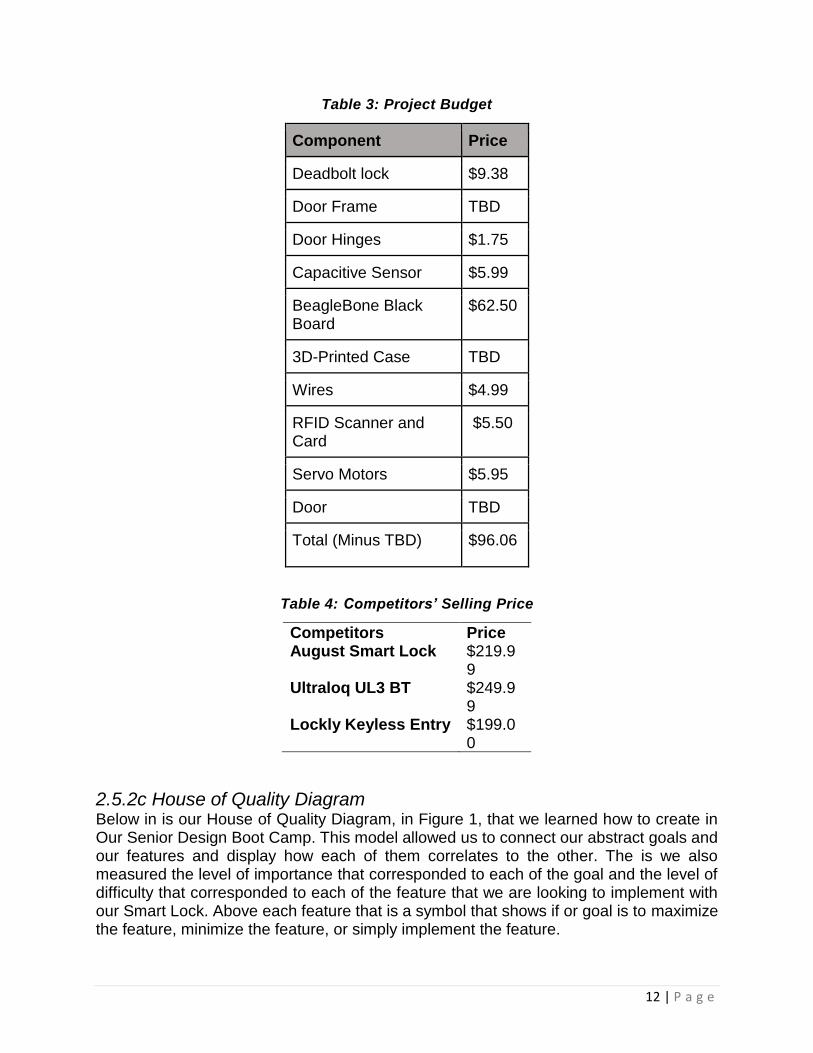
2.5.2b Budget Tables 3 and 4, project budget and competitors selling price, outline the price of each individual component used to build the Keyless Entry project and comparing the prices of similar products on the market. These different comparisons help by determining how reasonable the groups build is, because if the total of the components price was more than the competitors selling price then the project would not be feasible. The total of the component price should be low enough so after parts acquisition and theoretical labor cost the product could hypothetically be sold and make a profit.
12 | P a g e
Table 3: Project Budget
Component Price
Deadbolt lock $9.38
Door Frame TBD
Door Hinges $1.75
Capacitive Sensor $5.99
BeagleBone Black Board
$62.50
3D-Printed Case TBD
Wires $4.99
RFID Scanner and Card
$5.50
Servo Motors $5.95
Door TBD
Total (Minus TBD) $96.06
Table 4: Competitors’ Selling Price
Competitors Price August Smart Lock $219.9
9 Ultraloq UL3 BT $249.9
9 Lockly Keyless Entry $199.0
0
2.5.2c House of Quality Diagram Below in is our House of Quality Diagram, in Figure 1, that we learned how to create in Our Senior Design Boot Camp. This model allowed us to connect our abstract goals and our features and display how each of them correlates to the other. The is we also measured the level of importance that corresponded to each of the goal and the level of difficulty that corresponded to each of the feature that we are looking to implement with our Smart Lock. Above each feature that is a symbol that shows if or goal is to maximize the feature, minimize the feature, or simply implement the feature.

13 | P a g e
Next to the feature are the names of each of the members of our group and the level of importance that each of the goals hold to us based on the individual feature we are undertaking for our project, that has a chart that also maps out the individual importance for to each member. The House of Quality was an important diagram to create because it allows us to visualize the connections between or goals and features, and be doing this it was easier for use to divide our features into the ‘Tier’ lists shown above in this paper.
Figure 1: House of Quality

14 | P a g e
2.5.2d Block Diagram The figure below, Figure 2: Keyless Entry Block Diagram, illustrates the basic functionality of the Keyless Entry Project. It highlights the various aspects of the design and the intercommunication between the various components. The figure also shows how the group decided to break up the research amongst the group members.
Figure 2:
Figure 2: Keyless Entry Block Diagram
Communication
Control Line
Power Line
• e
• e
• e
• e
• e
• e
Don
Ethan
Ethan
Kevin
Ethan
Justin
Ethan
• e
• e
• e
• e
• e
• e
• e
To be acquired
designing
testing
completed
researching
acquired

15 | P a g e
2.5.2e Milestones The below tables: Table 5: Senior Design 1 Milestones and Table 6: Senior Design 2 Milestones, show the groups timeline for completing the Keyless Entry project. The timeline with specific milestone deadlines was design in order to keep the group on task and organized. This approach ensures the group develops a well-rounded and thoroughly developed project.
Table 5: Senior Design 1 Milestones
Senior Design 1
WEEK DATE MILESTONE
WEEK 4 June 4th Create a table of contents, research and pick components
WEEK 5 June 11th Start writing research paper
WEEK 8 July 2nd Complete ½ of the research paper
WEEK 10 July 16th Finish individual writing and assemble paper
WEEK 12 July 30th Turn in the completed paper
Table 6: Senior Design 2 Milestones
Senior Design 2
WEEK DATE MILESTONE
WEEK 1 August 26th Order Parts
WEEK 3 September 9th Test parts received
WEEK 5 September 23th Begin assembling the prototype
WEEK 8 October 14th Test and modify prototype, order new parts if needed
WEEK 12 November 11th Have a complete functioning build finished
WEEK 13 November 18th Prepare Presentation
WEEK 15 December 2nd Final Presentation
2.5.3 User Constraints This is the section where we outline each of the assumptions we are making about our potential users. The first of our user constraint is that we assume that our user know how to us a smartphone. This is importance because without the use of a smartphone the lock cannot have its full capabilities realized using our application. Next is that we assume that our users have a smartphone, this would also be a barrier to the use of our application. We are assuming that our users have a place of residence, because without this the

16 | P a g e
Smart-Lock is not usable in any fashion. Another one of our assumptions is that the user has a home Wi-Fi network, without this there would be limitations placed on our Smart-Lock. Final assumption that user is moderately competent with tools, because our Smart-Lock is meant to be easy to install but the user must have slight experience with home improvement. These user constraints will play a factor in the design of our project as we go forward.
3 Research This section is comprised of the research done in order to properly develop this project. The workload was distributed amongst the group into fourths in order to obtain a vast depth of knowledge. The team then collaborated what they had learned in their own research with the team. After research had been concluded parts were to be purchased and assembly and testing was to begin. This project requires a significant amount of research to complete the project in the time that is allotted. This section is important because it combines our current knowledge of Computer and Electrical Engineering with the forms of Smart-Locks that have been implemented by companies. The research done in this section is also used to help resolve any problems that arise during the implementation and testing portions of this project.
The research done for this project spanned many topics such as the locks that are already on the market to the components that we are considering implementing in our project. The Industrial Products sub-section is where the research done on other Smart Locks on the markets is placed form this research, we were able to determine which features are feasible to include in our design. While performing research we discover other designs that are comparable to the project this research is place into the Similar Projects subsection of this paper. The User Interface sub-section allows us to give a brief description of how the user interacts with each of the feature based on the research. Research done for the options that we have for each of the components was also included in this paper.
3.1 Industrial Products Although our idea to create smart lock is something that has already been manufactured before by various companies and been available on the market for a few years now. This gives us the opportunity to learn from this companies and improve on the ideas for our project. Each of these companies define smart lock in a similar fashion with various forms of design. We are going to focus on three companies and review multiple designs that each company has on the market.
3.1.1 August Lock The August Lock company manufactures two different smart locks, Smart Lock and Smart Lock Pro, and both are compatible with a Wi-Fi Bridge that is also manufactured by August Lock, shown in Figure 3. This Wi-Fi Bridge enables the following features in both
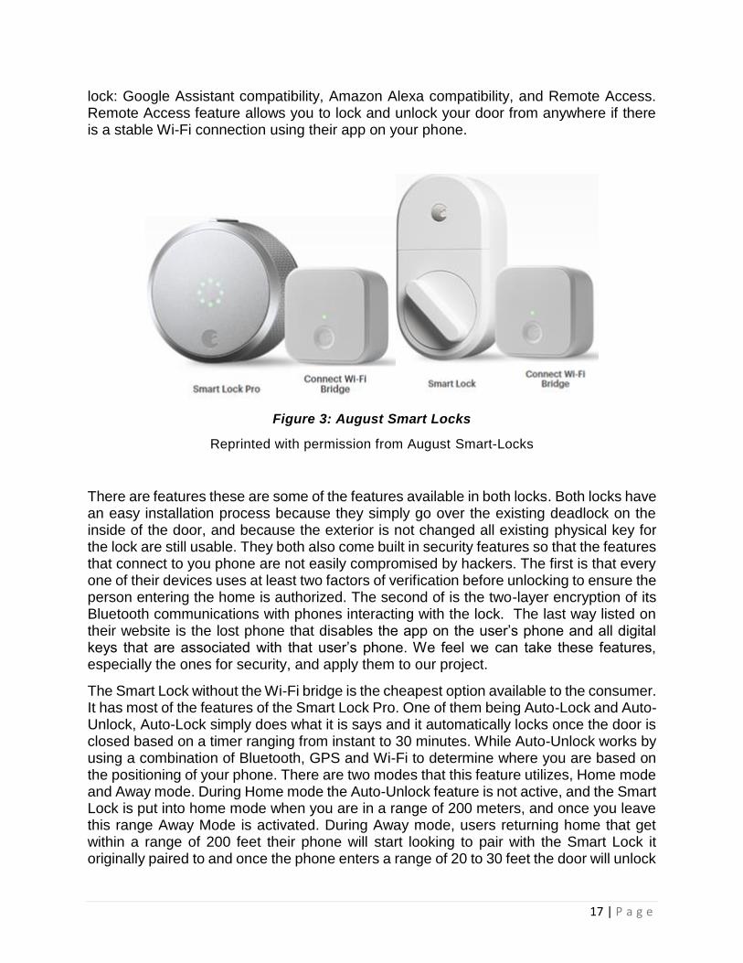
17 | P a g e
lock: Google Assistant compatibility, Amazon Alexa compatibility, and Remote Access. Remote Access feature allows you to lock and unlock your door from anywhere if there is a stable Wi-Fi connection using their app on your phone.
Figure 3: August Smart Locks
Reprinted with permission from August Smart-Locks
There are features these are some of the features available in both locks. Both locks have an easy installation process because they simply go over the existing deadlock on the inside of the door, and because the exterior is not changed all existing physical key for the lock are still usable. They both also come built in security features so that the features that connect to you phone are not easily compromised by hackers. The first is that every one of their devices uses at least two factors of verification before unlocking to ensure the person entering the home is authorized. The second of is the two-layer encryption of its Bluetooth communications with phones interacting with the lock. The last way listed on their website is the lost phone that disables the app on the user’s phone and all digital keys that are associated with that user’s phone. We feel we can take these features, especially the ones for security, and apply them to our project.
The Smart Lock without the Wi-Fi bridge is the cheapest option available to the consumer. It has most of the features of the Smart Lock Pro. One of them being Auto-Lock and Auto-Unlock, Auto-Lock simply does what it is says and it automatically locks once the door is closed based on a timer ranging from instant to 30 minutes. While Auto-Unlock works by using a combination of Bluetooth, GPS and Wi-Fi to determine where you are based on the positioning of your phone. There are two modes that this feature utilizes, Home mode and Away mode. During Home mode the Auto-Unlock feature is not active, and the Smart Lock is put into home mode when you are in a range of 200 meters, and once you leave this range Away Mode is activated. During Away mode, users returning home that get within a range of 200 feet their phone will start looking to pair with the Smart Lock it originally paired to and once the phone enters a range of 20 to 30 feet the door will unlock
18 | P a g e
and return to Home mode. These to features along with ‘Doorsense’ which monitors the lock’s status are done thorough the August lock app. Seeing these features being done and, on the market, gives use a clear idea of how to dissect them and implement them into the app we are developing for the project. The Smart Lock is power by 4 AA alkaline batteries and requires 110-240 volts to operate.
The Smart Lock Pro is the upgraded version of the Smart Lock with a design that is appears simpler but has a couple of features that set it apart from the original. The first being that it has Z-Wave Plus support, which connects it to a central hub network in your home that can be access and controlled through your home devices such as, a laptop, smartphone, or tablet. The second is it compatibility with Siri and Apple Home Kit which allow you to control the lock with voice commands using any Apple device. The final feature to be discussed is one that they both share with is virtual keys, basically they are digital keys that can be granted to others for a certain amount of time while the lock records who is using which key at which time. The two features listed for the Smart Lock Pro seem to fall into the realm of stretch goals for our project. The Smart Lock Pro is also power by 4 AA alkaline batteries and requires 110-240 volts to operate. Below are examples of both versions of the August Smart Lock.
3.1.2 Schlage The Schlage company manufactures two smart locks, similar to how the August lock manufactures two version. One of these versions is the Schlage Encode that is more expensive with slightly more feature. The other version is the Schlage Sense which cheaper and comes with less features, but a Wi-Fi adapter manufactured be Schlage can be purchased to add those missing features on to this lock. Both of the locks share certain features such as that they are both able to have their status checked and locked or unlocked via an app, although if you are using the Schlage Sense you would require a Wi-Fi adapter to use it and applies for all feature that go through the app.
This app also for the creation of PIN numbers specific to each person and track who enter the home. The Schlage Encode holds up to 100 different PIN numbers while the Schlage Sense only holds 30 PIN numbers, which are enter into a keypad that both versions have on the external part of the door. Both locks are powered by four AA alkaline batteries, which eases installation because there is no need for hardwiring required for power. It also utilizes an LED so that it can alert the user to when the lock’s batteries are running out of power, which is a feature it shares with the August Smart Lock. The clear negative to this option is the fact that because it is on the outside of the door the user will have to change keys as opposed to the August Smart Lock the user can keep their keys. Although the Schlage is cheaper than the August Smart Lock. Figure 4 are examples of both Schlage locks with Schlage Sense on the left and Schlage Encode on the right.

19 | P a g e
Figure 4: Schlage Smart Locks
3.1.3 Kwikset Kevo The company Kwikset has been manufacturing locks for 70 years and recently has entered the smart lock market with the Kevo and Kevo Convert. The Kevo utilizes one feature that the other locks have not, which is the unlocking through the use of a touch sensor, named ‘Touch-to-Open’. This feature is achieved by having the phone pair to the lock and once it enters a certain range in the exterior the feature awaits touch to unlock. This feature is the only feature that is not available in the Kevo convert because it only replaces the interior of the lock. This lock seems to be the most lacking when it comes to features compared to the other locks. Figure 5 shows the Kwikset Kevo Contemporary as left two locks while the Kwikset Kevo Convert is the rightmost lock.

20 | P a g e
Figure 5: Kwikset Smart Locks
Reprinted with permission from Kwikset
Both models are to use with the app developed by Kwikset which also for the use of remote locking and unlocking, status checking, and the distribution of virtual keys. The app also tracks who enter the home when these virtual keys because each one is unique. These features seem to be standard for apps that are used for smart locks. The installation difficulty can vary as well depending on the model of lock that is purchased. Both of the models are compatible with Kevo Plus accessory which does the same functions as the Wi-Fi adapter for the locks manufactured by other companies. This means that is expands the range of the remote features in app to access the lock. The Kevo also has an exclusive accessory, the Kevo Key Fob which can use the ‘Touch-to-Open’ feature without the use of a smartphone. The Key Fob can be pair with up to 25 locks. These locks are powered by 1 AA battery.
3.2 Similar Projects The proceeding sections were used to further the groups knowledges on the smart lock functionality. Different projects were discovered and used to do develop the groups on the project.
3.2.1 TI Battery Powered Smart Lock with Cloud Connectivity This is a design that we found on the Texas Instruments (TI) website that helped show us how we can implement the remote locking and monitoring portion of our design. Although this design uses a different microcontroller, SimpleLink Wi-Fi CC3220S. This lock was built with seven parameters in for its key specifications Input power source, Sensor Type, Average current consumption, Lock or Unlock events, Motor type, User interface, and Theoretical battery life. The lock was designed to be powered by a 5-volt

21 | P a g e
source which is shown in two ways, first being a USB connection directly to the microcontroller and the other being four AA batteries. The sensor type used for this design is an Inertial Measurement Unit. The average current consumption was considered with this design for each component, the motor consumes 42 microamperes, the Wi-Fi on the microcontroller consumes 377 microamperes, and the Bluetooth Low Energy on the microcontroller consumes 40 microamperes.
The number of Locking events was determined using a theoretical battery life of 1.26 years as its basis and from there it was determined that it can achieve this life cycle with 24 locking event a day. The Motor type used for this design is a DC powered Brushed motor. The lock’s User Interface that it was designed for is any Wi-Fi enabled mobile device for example, a tablet or smartphone. This design also demonstrates a few security measures that we can implement into our design such as the use of Failsafe files and Signature verification. Below is the block diagram from the design and as you can see it is fairly simple and leaves room for us to add onto as well as replace components of it with the parts we choose to use for our design. Comparatively our design is going to have more modes of entry so this design is only going to be used as reference for phone app component because it shows the inner works of the apps that are standard for the companies that manufacture smart locks mentioned in this paper. Figure 6 shows a block diagram of the protocols for a Texas Instruments smart lock with cloud connectivity.
Figure 6: TI Smart Lock Block Diagram
3.2.2 TI Smart Lock Reference Design on 4x AA Batteries This is another design for the design we found to use as reference for this project for its energy efficiency. This design chose to use AA batteries as its power source do to their popularity in the smart lock business as a power source and their high voltage capacity. This lock was designed with many Key System Parameters, the first being the Input power source which uses four AA batteries. Another parameter is the batter life which is estimated to be 5.29 years with there being 24 locking events per day. This design also utilizes a Brushed DC motor the same motor used in the previous TI design we discussed in this paper. It uses Bluetooth that is integrated into the microcontroller for its’ wireless communications and can be pair with various remote-control applications such as ZigBee RF4CE. The User Interface is simple to keep power low with six RBG LEDs. The battery life of this design is lengthened by having low standby currents and long off-state intervals of each component in the system. The component used to lower standby currents is TI’s

22 | P a g e
light load DC/DC converter. This lock was only designed to demonstrate the lowlight- load topology can extend battery life is only meant to be the first step and more feature can be built onto it such as remote access. Figure 7 outlines the design of the 4x AA Battery TI Smart Lock with a block diagram.
Figure 7: TI Smart Lock with 4x AA Batteries Block Diagram
3.3 User Interface There are multiple forms of User Interface because there are multiple forms of entry designed for our lock. The first form of user interface will be the fingerprint sensor which will be locate on the exterior of the door and be on standby mode until a user input a fingerprint. The RFID sensor is our second form of user interface that will be on the exterior of the door accompanying the fingerprint sensor. The RFID sensor will have read and write capabilities so the user will able to create as many keys as necessary for the user. The final and required form of user interface is the app we are developing for Android and iOS so that the user will have remote control of their lock as well as allow them to remotely check the status of their lock. These are just the forms of User interface that Tier 1 goals for our lock there are still more form from our Tier 2 and Tier 3 lists that will be discussed in the subsections of this section.
3.3.1 Fingerprint Sensor: The Fingerprint Sensor integration is a Tier one goal of our project. The sensor will function similarly to the way a fingerprint sensor on smart phones works. The sensor will be on standby until the user prompts the sensor by pressing one of the fingers that is

23 | P a g e
registered in the lock’s record of fingerprints. Once the scan is complete the door will be unlocked and simultaneously a alter will be sent to the app and the primary user will be alerted to who has entered their home. If the fingerprint is not valid then the door will remain locked, there will be 10 opportunities available until the door lock disables for 30 minutes and an alert is sent to the primary user’s smartphone through the app. There will also be two LEDs, one red and one green, attached to the exterior of the lock to signify if the fingerprint entry was valid or invalid.
3.3.1a Fingerprint Sensor Comparison When research began into this feature, we quickly realized we would have to choose between two type of fingerprint sensors. The optical fingerprint sensor which is realizes on a camera to capture the image of the fingerprint. Although this option is susceptible to forging the fingerprint because it only takes a 2D image. The capacitive fingerprint records the fingerprint uses a set of small capacitors to record the ridges of the fingerprint to create a pixel image that cannot be copied. Table 7 presents considered options for fingerprint sensors to use. The price and pin count are the primary statistics considered.
Table 7: Fingerprint Sensor Comparison
After choosing which classification of fingerprint sensors would be ideal for the project, the next step is to choose which specific fingerprint sensor must be ordered. This is done by comparing the price points, pin counts and operating voltages of each sensor. In an ideal situation the goal is to have the cheapest, most efficient, and most power effective design. Rather than focusing on the data transfer rate for the 2D image captured by the sensor, our focus is that the operating voltage is low enough to not impede any other connections that will be necessary throughout the design. The price also needs to be low enough to fall within the ideal budget that is required for this project.
The Capacitive Fingerprint Reader available at the Waveshare website is our first option. The applications for this component list that is can be used to create a fingerprint lock. It has an operating voltage of 3.3 to 5 volts with its dynamic current being less than 40 milliamperes. The communication of the component can use both USB or UART interface with the PCB board we are designing for the project. The dimensions are relatively small being 45x30 mm for the module and 33.4x20 mm for the sensor.
The GT-521FX2 available at Digikey is our second option and it is an optical sensor. The CPU of the component has an operating voltage that varies from 3.3 to 6 volts while the sensor has a constant voltage at 3.3 volts. The operating current of the CPU is less than
Model Vendor Price Pin Count
Capacitive Fingerprint Reader
Waveshare $38.99 6
GT-521FX2 Sparkfun $35.95 8
Parallax Inc. 29126 Digikey $40.00 6

24 | P a g e
130 milliamperes while the sensor has an operating current of less than 3 milliamperes and a standby current of less than 5 microamperes. The communication of this component would also use both USB or UART interface with PCB board we are designing for the project. The dimensions of the component are 16.9x12.9 mm and the dimensions of the sensor are 14x12.5 mm.
The component numbered 29126 manufactured by Parallax Inc is our third option and available at Digikey is also an HD-optical sensor. The operating voltage of this part is 3.3 to 7.5 volts with an operating current of less than 50 milliamperes. The communication of this component would use UART interface with the PCB board we are designing for this project. The dimensions of the PCB attached to the sensor are 45.7 x 28.2 mm and the dimensions of the sensor are 50 x 23.2 x 25 mm.
3.3.2 RFID Sensor: The RFID sensor integration is a Tier one goal of our project. The sensor will function similarly to how and hotel room door functions, except without the sound associated with the hotel door. The sensor will be located on the exterior of the door alongside the fingerprint sensor and utilize the same LEDs that fingerprint sensor uses for valid and invalid. This sensor will function in a similar fashion to the fingerprint sensor, meaning it will remain on standby until an RFID tag registered to the lock enter the operating range and it will be scanned. From these results of the scan the green a LED will flash, the door will be unlocked, and an alert will be sent to the phone of the of the primary user to verify that the RFID tag is valid. If the tag is in valid the user will have three more attempts with that tag to unlock the door and if these attempts are unsuccessful the lock will shut off for 30 minutes and an alert will be sent to phone of the primary user. The idea for this user interface originated from observing the way hotel doors operate and there is multiple tutorial that show RFID sensors being used for this very purpose.
3.3.2a RFID Sensor Comparison When research began on the portion of the project realized that we would have to choose which frequency that our lock would operate on we narrowed down the options to 13.56MHz, 134.2kHz, and 125kHz. Both 134.2kHz and 125 kHz fall into the category of Low Frequency RFID(LFRFID) this and normally used to track farm animals. While the 13.56MHz falls into the High Frequency RFID(HFRFID) which primarily used for monetary transactions as well as data transfer. The effective range we are going to be focusing on and implementing for the project is the short-read range of the reader. The reason is because our project is to design a Smart Lock it would be a major design flaw to have the RFID entry method have a large read range. The typical short read range of an LFRFID is 10 centimeters while the HFRFID has a range of 10 centimeters to 1 meter. We also decided that all the modules that are being considered must be able to read and write to the RFID tags. Table 8 presents considered options for RFID sensors to use. The price and pin count are the primary statistics considered.

25 | P a g e
Table 8: RFID Sensor Comparison
Model Vendor Price Pin Count
DLP-RFID2 Mouser/Digikey $34.95 14 RWD-QT-R2-ND Digikey $40.37 24
RI-STU-MRD2 Digikey $92.40 30
The first option is the DLP-RFID2 available on Digikey and Mouser which falls under the umbrella of the HFRID. This option has an operating voltage of 3-5 volts as well as operating current of 55 milliamperes when in use and 4.4 milliamperes when idle. The DPL uses TTL serial interface for communication when it interfaces with a simple microcontroller and it can also use an USB interface to interact with an PC. The fact it can use an USB interface will make it easier for us to troubleshoot while we are in that phase of our development as well as make it easier to program new tags to use once the device is fully functional. This component also comes with an internal antenna equipped to it that is one less pat we must worry about procuring if we decide to use this component. Although if necessary, it can be equipped with an external antenna. It has the dimensions of 41.91 x 18.669 x 4.318 mm (L x W x H).
The second option is RWD-QT-R2-ND available on Digikey falls under the umbrella of LFRFID with a frequency of 125 kHz. This component has an operating voltage of 5 volts with an operating current of 10 milli amperes. There is one flaw with this component as it relates to our project and that is that it requires a 700 µH antenna to be attached to it so that it can use it’s read/write capabilities. This can be a problem because of time for that antenna to be order as its own separate part as well as the monetary cost is associated with obtaining this extra part. The RWD-QT uses an TTL RS232 for its communication with a host system and in this case that would be the microcontroller on our PCB board. Its range is larger than the typical being 20 cm compared to the typical 10 cm. This component also has a feature that is unique to it among this options and that is that it uses Adaptive Sampling this allows for it to make continuous adjustments and re-tune the sampling to account for charges in the RF field, thus in insuring that the tag is read accurately in real-world condition. The dimensions of the RWD-QT-R2-ND are 30.5 x 18 mm.
The third option is the RI-STU-MRD2 available on Digikey falls under umbrella of LFRFID with a frequency of 134.2 kHz. This component has an operating voltage between 2.7 and 5.5 volts while have two separate power supplies that must have the same voltage. This can be a tedious challenge that we would have to take into consideration when we are designing our PCB board. The component also uses TTL interface for communication to a microcontroller and USB interface for communication to an PC similarly to how the DLP-RFID2 interfaces with both microcontroller and PC. This means they would share similar benefits of having both interfaces available. This component can be implanted in two way one being dual in line module (DIL) and the other being surface mount device (SMD) for this project we will be using the surface mount device implementation. The dimensions of the SMD implementation are typically 27.9 x 22.8 mm and weighs 3 grams. This component requires an external antenna with 47µH and a Q-factor between 10 and

26 | P a g e
20. This means if this option is taken it will have the concerns that our second option the RWD-QT-R2-ND has if it is implemented into our project.
3.3.3 Keypad: The Keypad is a Tier two goal for our project. This will be a wired keypad that attaches to a wall near the door and pair to our smart lock. The Keypad will be connected to the Bluetooth component and have two LEDs, one green and one red, to determine the status of the batteries and if the batteries need to be replaced. Each PIN will be specific to the individual user while being viewable and changeable on the app. This feature was heavily inspired by the Schlage Encode which was discussed on this list. The feature was also inspired be other smart lock in this paper such as the August Smart Lock Pro.
3.3.3a Keypad Comparison
The focus on the comparisons between the different keypads is for a minimal price, a
durable surface, as well as low operating values. In an ideal situation we would want
low operating values and a durable surface, which is relatively easy to find. The issue is
that we need to maintain our project under a budget in order to have economic
efficiency. Due to this reason, our focus will have to be a compromise between low
operating values and a minimal cost. If the opportunity cost is worth an upgrade to a
more durable surface, then we will purchase a slightly more expensive keypad module
for the design. Table 9 shows a small comparison of the Keypad devices that we are
considering for this product.
Table 9: Keypad Comparison
Model Vendor Price Pin Count
1568-1856-ND Digikey $4.50 9
GH5003-ND Digikey $19.92 8
1528-1136-ND Digikey $3.95 7
Option 1:
This is a 12 key keypad that contains the 0-9 keys as well as a star and pound key. It is a simple connection with two pins that aren’t meant for programming. The keypress resistance is between 10 and 150 ohms. It has a sleek and simple design that can easily be placed in the exterior of the smart lock. This appears to not be as susceptible to wear and tear, which is important since the smart lock is meant to be placed on the outside of doors. This keypad is also one of the cheaper options that were encountered on the online shops.

27 | P a g e
Option 2:
This is a 16 key keypad that contains the 0-9 keys as well as the star, pound and A-D keys. This is an 8-pin device, with one terminal pin used for the connections. This acts less like a resistor and more like its own device. It runs at 5 milliamps, has an internal resistance of about 100 ohms and has operating temperatures between –30 degrees and 80 degrees Celsius. The durability for this device appears to be much greater than that of the 1568-1856 model, but it is not as cost effective.
Option 3:
This is a 12 key keypad that contains the 0-9 keys as well as a star and pound key. It has 7 pins for programming purposes and relies on a microcontroller. This is a polyester keypad that appears easy to use but requires heavier pressure to operate. The keypad is also a sheet rather than an actual plastic case like the previous options. Although it is one of the cheapest products on the market, it’s durability might raise concerns and server impractical for the design of the smart lock.
The keypad device of choice for our project will be the 1568-1856-ND model. This keypad gives us a simple and reliable connection, as well as an affordable price to stay within the intended budget. The second option appears to be the most durable and efficient option, but it’s price falls well above the budget we have given ourselves. Although the third option is simple and cheap, its durability causes too much concern for the consistency of the overall device. This leaves the first option as the best choice for the keypad device due to the fact that it easily falls within the budget and has a reliable durability. The device also has a smaller pressure requirement in comparison to the other options, which adds convenience. Figure 9 is an image of the circuitry of the keypad. The in and out pins are labeled 1 and 7. Design is modeled after the design in the datasheet for the keypad.
Figure 8: SparkFun Keypad
Reprinted with permission from CC BY 2.0

28 | P a g e
Figure 9: SparkFun Keypad 1568-1856-ND Schematic
Reprinted with permission from SparkFun
3.3.4 Bluetooth The desired features of the Bluetooth module would be to be low powered and have an efficient data transfer rate. Range is a value that can be observed, but due to the fact that this product does not require an emphasis on distance we will not be using this as a decisional factor. In this section we will be comparing four different Bluetooth modules and deciding which one we will be using for the product. All of the options for this section were found on the Digikey website, and are manufactured by Cypress. The options range from Bluetooth v4.0 devices to Bluetooth v4.2 and all are low energy modules. There are different tradeoffs depending on the module that is being observed, processing power and memory tends to sacrifice the option of the module being a low power device. The maximum voltage that can be used by this device should be 6V, so any option that goes above that limit will be removed. If a module is low powered, yet still powerful it might sacrifice too much range or it could affect the cost. Table 10 below shows a small comparison of the Bluetooth modules that we are considering for this product.
Table 10: Bluetooth Module Comparison
Model Vendor Price Pin Count
428-3655-ND Digikey $4.40 48
428-3657-ND Digikey $16.19 48
428-3656-ND Digikey $13.08 48
CY8C4128LQI-BL543 Digikey $6.50 56
29 | P a g e
Option 1:
This a Bluetooth v4.1 device that has a reduced range of 50m compared to the previous Bluetooth versions and a reduced data throughput of about 0.27 Mbps, but it has relatively low power consumption. The range isn’t as important either since this is to unlock the lock to a door, which is something that is done while relatively close to the door. The voltage supply required is between 1.4V and 3.6V and functions at a frequency of 2.4 GHz.
Option 2:
This is a Bluetooth v4.0 and its power is much greater than that of the 3655. It has a memory size of 320kB ROM and 60kB RAM, which gives an option for user storage within the device. This allows easier access to recurring users. The device also has a data rate of 1.0 Mbps which is significantly higher than that of the 3655. Although this device has more power than the 3655, it has an operating voltage of 3.8V and a price of $16.19 per unit which is greater than what is wanted for this project.
Option 3:
Another Bluetooth v4.1 device, similar to the 3655, it has a reduced range of 50m and a data throughput of 0.27 Mbps. The device operates with a memory size of 60kB RAM, which means the device can have user storage capabilities. The device also has the same voltage range as the 428-5655, which is between 1.4V and 3.6V. This is a midpoint in power and power cost between the 3655 and the 3657, but with a cost of $13.08, it is still a bit higher than what we intend on spending.
Option 4:
This device is actually a Bluetooth v4.2 module, which has the greatest packet data unit size of the previous options. The usual Bluetooth v4.0 and v4.1 has a PDU size of about 27 bytes, this module actually has a packet size of 251 bytes. The theoretical data rate is about 1 Mbps for this module which is the highest of all the options, which could allow faster access to the user’s home. Since more packets can be transferred at a time, this also reduces the opportunity for error which also gives faster responses from the device. The range of this device is also more or less the same as the Bluetooth v4.1, but it’s operating voltage is slightly greater by having a range of 1.8V – 5.5 V. Since the price is only about 2 dollars per unit greater than the cheapest option and its power is much greater than this appears to be one of the better options for a Bluetooth module.
The Bluetooth device of choice for our project was the CY8C4128LQI-BL543. Although it had an operating voltage that was slightly greater than the other options, the other features it has a much more powerful. This device has a flash memory size of about 256 kB, ROM memory of 8 kB and SRAM of about 32kB. This is incredibly important to have due to the fact that it gives the application the option to save different users to unlock/lock the door. This will allow easier and faster access to the user’s home. There is a range of 50m with the device, which is more than enough to simply unlock a door. The data rate is also incredible high compared to the other Bluetooth modules and it will allow efficient access and communication between the other features within our product. This device is also considered a programmable system-on-chip (PSOC) integrated circuit which allows it to act as a minor MCU device. These circuits are extremely easy to program and they
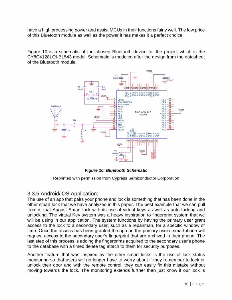
30 | P a g e
have a high processing power and assist MCUs in their functions fairly well. The low price of this Bluetooth module as well as the power it has makes it a perfect choice.
Figure 10 is a schematic of the chosen Bluetooth device for the project which is the CY8C4128LQI-BL543 model. Schematic is modeled after the design from the datasheet of the Bluetooth module.
Figure 10: Bluetooth Schematic
Reprinted with permission from Cypress Semiconductor Corporation
3.3.5 Android/iOS Application: The use of an app that pairs your phone and lock is something that has been done in the other smart lock that we have analyzed in this paper. The best example that we can pull from is that August Smart lock with its use of virtual keys as well as auto locking and unlocking. The virtual Key system was a heavy inspiration to fingerprint system that we will be using in our application. The system functions by having the primary user grant access to the lock to a secondary user, such as a repairman, for a specific window of time. Once the access has been granted the app on the primary user’s smartphone will request access to the secondary user’s fingerprint that are archived in their phone. The last step of this process is adding the fingerprints acquired to the secondary user’s phone to the database with a timed delete tag attach to them for security purposes.
Another feature that was inspired by the other smart locks is the use of lock status monitoring so that users will no longer have to worry about if they remember to lock or unlock their door and with the remote control, they can easily fix this mistake without moving towards the lock. The monitoring extends further than just know if our lock is

31 | P a g e
locked or unlocked it also allows the user to know who unlocked it with the accompanying form of entry that they used. The feature does not apply to any user that unlocks the door with the backup key meant for the lock.
The app will also give the user the option of creating level of access and make it so that certain secondary users can only use certain forms of entry. For example, a primary user with an elderly mother that has a habit of misplacing items can disable the RFID unlock feature for his mother so that her lost RFID tag will not cause any unnecessary security concerns while the mother will still be able to access her home with her fingerprint. The app will also allow for the termination of access privileges to secondary users when necessary as well as the transfer of primary user privileges when need. We choose these features after carefully analyzing the other smart locks that are on the market and choose the ones that were best suited tour design and added original features, we believed would better our design.
3.3.6 Alexa Interface: Amazon Alexa for voice control is a Tier two goal for our project. The user will be able to use Alexa to lock and unlock the door via voice commands. The user’s Alexa will also be able to read a record of who has entered and exited the home for the user’s convenience. We will be developing this portion of our lock using one of the many voice command software available on the amazon skills website.
The Alexa Interface is designed to be an ease of use feature that is not intended to be an
authentication method. Using voice authentication is a stretch goal that would require the
implementation of a microphone into the smart lock and a way to determine a user through
voice recognition. This is a challenging endeavor due to how vastly different it is from how
the other sensors function as a security measure. However, it is possible to use Alexa on
the phone app to lock and unlock the door as an extension to the MAC address
authentication method.
The MAC address already verifies the phone as a user. Thus, a setting can be
implemented to be able to use Alexa to unlock the door as one of the unlocking
mechanisms common to smart locks is the ability to unlock and lock doors from the phone
app. This would simply be issuing that command through voice rather than going into the
app.
A voice profile can be implemented by Alexa as your mobile device can recognize your
voice compared to other users. A filter that can only recognize a certain voice profile as
a user may be set on the phone app to prevent other anonymous parties from abusing
the locking and unlocking feature on your device. This would increase the security of
this locking and unlocking method enough to consider it an authentication method.
While implementing Alexa is a tier 2 goal on the phone app alone, using Alexa’s voice
recognition as a form of authentication on the smart lock end would serve as tier 3 goal.

32 | P a g e
3.4 Internal Components The preceding sections discuss the research of components that function as a result of user interface. These components consist of the motor, motor driver, accelerometer, and LEDs.
3.4.1 Motors
This section of the document discusses the different motors that the group considers using to turn the doors deadbolt in order to properly unlock and lock the door. The motor needs to have a high enough torque rating to turn the deadbolt. This converts to A key feature desired by the motor is its ability to be free turned when the motor has no power. The reason this feature is desired is so if the Keyless Entry no longer has power the user can still open the door by turning the key. If the motor has a high torque when under no power, then the user may break the key or not even be able to turn the key resulting in being locked out. The motor will be mounted to the doors thumb turn on the inside of the door. According to the standard ANSI/BHMA A156.40 Residential Deadbolts, this deadbolt is rated at grade 3 security, explained in the A156.40 standard. This lock is rated as, ANSI/BHMA Grade 3 Security.
3.4.1a DC Motor A DC motor functions by taking electrical energy and transforming it into rotational mechanical energy. The motor uses electromagnetics to induce a current into a conductor that is placed in a magnetic field. The motor consists of a rotor and stator. The motor has either permanent magnets or electromagnetic windings on the stator. The rotor contains coiled winding that that are powered by DC current, when the current flows through these winding a magnetic field is induced. Rotation then occurs due to one side of the rotor being attracted to the magnetic field of the stator, while the other side is repelled. A commutator determines the direction of flow of the current, causing continuous attraction and repelling. This causes the rotor to continuously turn.
There are various types of DC motors. The various types of brushed motors are permanent magnet DC motors, series motors, and compound motors.
There are also brushless motors. These motors are similar to the permanent magnet
synchronous motors but can also be an induction motor or a switched reluctance motor.
Brushed motor is useful because they are very powerful. Also, they have high speed
and can be easily controlled with the CPU.
A brushed motor is not needed in the group’s application due to the fact that the motor needed only requires high torque and not high speed. A brushless motor will suffice since it can still be controlled with precision and can be found for a reasonable price.

33 | P a g e
3.4.1b Servo Motor Servo motors are considered one of the most versatile type of motors. They are very compact which is an important factor of the design due to the size constraint. Even though servos are small, they output high torque at a very power efficient rate.
A servo motor is comprised of a small DC motor, potentiometer, control circuit, and a set of drive gears that are attached to the control wheel. The servomotor has a rotor actuator, this allows for very precise control of acceleration, velocity, and angular position. The simplicity of controlling the servomotor comes from the motor having a position sensor that delivers feedback of the present position of the motors shaft and it compares it to the desired position. The motor is easily controlled by nearly any microcontroller. This is a desired trait the group is looking for since many sensors will be used and connected to the microcontrollers input and output pins.
The servomotor uses closed loop analysis to control the motors movement, speed, and desired position. The input signal that drives the servomotor can be controlled by either an analog or a digital signal. These signals control the motors functionality and a varied based on its desires speed and position. Servo motors are controlled with pulse width modulation (PWM). In PWM a digital signal produces a square wave. When the signal is high power is being delivered to the motor, conversely when the signal is low no power is being delivered. The time of the pulse, or the amount of time the signal is high, refers to the duty cycle of the square wave. The duty cycle is tuned to the desired angular position, the greater the duty cycle the further the shaft will rotate.
The motor servomotor can only rotate 90 degrees in either direction, resulting in a total
range of 180 degrees. The motor has a neutral position, essentially its starting position.
From its neutral position it has the same amount of possible rotation variability in the
clockwise and counterclockwise direction. The pulse width modulation signal, discussed
earlier, is used to determine the position of the shaft based odd of the total duration of
the pulse that is sent. The length of the pulse determines the length of the turn. Figure
11 shown below, demonstrates how the variation of the pulse of a 20ms cycle affects
the position of the servomotor.
Figure 11: Variable PWM Controlled Servo Position

34 | P a g e
Power is provided resulting in rotation of the shaft, once the desired rotation is achieved power is no longer supplied. Servos are controlled with proportional control; this means the speed of the motor is proportional to its angular position. The motor will accelerate initial and then decelerate once it gets close to its desired position, resulting in precise angular positioning.
The servo motor that the group is considering using will be researched in more detail. This research is discussed in section 5.2.1.4 Servo Motor.
3.4.1c Stepper Motor A stepper motor is another variation of a DC motor. It is a brushless motor that rotates in steps. The stepper motor divides a full angular rotation up into steps. These step sizes vary in degree and allow for a wide range of angular control options. The distance that the shaft of the motor rotation is controlled by converting several impulse square waves into a distinct angular rotation of the shafts position.
The purpose of rotating in steps is that this method allows for very meticulous
movement, without the need for any feedback sensor. The stepping sizes have a variety
of different ranges that vary in degrees. Generally, a stepper motor has a static magnet
for the rotor, it is encircled by stator windings. Current is controlled and flows through
the different stators in steps, this in turn creates electromagnetic poles. As the
controlled current steps through the proceeding windings it causes propulsion of the
motor.
3.4.2 Motor Driver Dependent on the motor selected to lock and unlock the door a motor drive may be needed for proper functionality. Motor drivers serve as a programmable device that controls the operation of the motor. Motors require a high amount of current, and the microcontroller that controls the signal of the motor does not output enough current to properly drive the motor. The motor driver takes the low current control signal from the microcontroller and transforms it into a high current signal that can be used to drive the motor.
The motor driver that the group is considering using is Pololu Dual DC Motor Driver. This motor can be used to control bidirectional DC motors, also this driver can be used to drive a stepper motor. Therefore, this motor satisfies the need for whatever motor is selected due to the fact that servo motors do not need a motor driver since they have built in circuitry to drive them.
This motor outputs one amp per channel with a max output of three amps per channel. It can supply 4.5 to 13.5 volts. The board is very compact, so it meets the desire of having a compact system. It has a built-in thermal shutdown circuit, so if overtemperature occurs it will shut down resulting in protection of the motor and the motor driver. Also, the driver

35 | P a g e
has a maximum pulse width modulation of 100 kHz, so the stepper motor has a wide range of speed controllability. The motor driver also features a TB6612FNG, which is the driver IC, power supply capacitors and reverse battery protection on the motor supply. The complete table of the motor driver specifications are listed below in Table 11.
Table 11: Motor Driver Specs
Pololu Moto Driver Specification
Motor Driver TB6612FNG
Motor Channels 2
Minimum Operating Voltage 4.5 V
Maximum Operating Voltage 13.5 V
Continuous Outout Current Per Channel 1 A
Peak Output Current Per Channel 3 A
Continuous Paralleded Output Current 2 A
Maximum PWM Frequency 100 kHz
Minimum Logical Voltage 2.7 V
Maximum Logical Voltage 5.5 V
Reverse Voltage Protection Yes
Dimensions 0.60in x 0.80in

36 | P a g e
3.4.3 Accelerometer An accelerometer is desired to allow further accesses to unlock the door. The idea is that the user can approach the door and knock on the door with a specific knock pattern and the CPU recognizes the knock sequence through the help of the accelerometer and then unlock the door.
Also, the accelerometer can be used for security purposes. The accelerometer can be implemented to detect a threat of a break-in and communicate with the CPU can send a signal through the android application that a possible intruder is at the door, or this can trigger an alarm to sound to deter the intruder from continuing to break-in. This would be accomplished by the accelerometer detecting high movement in the door, simulating shaking or any abrupt force other than a general knock.
An accelerometer measures acceleration. They are electromagnetic devices that sense dynamic or static forces of acceleration. This means that they can detect gravity, vibration, and movement. They can measure acceleration on up to three axes. These accelerometer’s contain capacitive plates that mover as forces act upon the sensor due to acceleration. The acceleration is then measured by calculating the changes in capacitance.
Accelerometers can be communicated with the CPU in various ways. The main ways that the accelerometer communicates with the CPU is: analog, digital, or pulse width modulation (PWM). For analog the accelerometers acceleration readings can be shown by analyzing the variance of voltage levels. If communication is digital the accelerometer communicates with the CPU through I2C or SPI protocols. Digital communication of the accelerometer is more reliable because it is less vulnerable to noise and it has more functionality.
A main goal of the groups project is to provide a reliable interface at a low power cost. Accelerometers are useful because they are usually very low-power devices, therefore the implementation of an accelerometer into the design will add functionality without increasing power consumption.
The accelerometer that the group is considering using is the Adafruit LIS3DH Triple-Axis Accelerometer. The LIS3Dh is a popular low-cost, low-power accelerometer. It has both SPI and I2C interfacing options, as well as interrupt output. It has multiple data rate options of 1 Hz to 5kHz. The accelerometer draws a very low current at only 2 micro amps. It has features of tap, double-tap, orientation, and freefall detection that will serve all the possible needs desired from an accelerometer. Also, the accelerometer has three additional ADC inputs that can be read over I2C. A list of the specifications of LIS3DH accelerometer is shown in table 12.

37 | P a g e
Table 12: Accelerometer Specs
3.4.4 Transistors and Diodes Transistors and diodes will be used for various purposes in this project. Diodes only allow current to flow in one direction, blocking it from flowing in the opposing direction. A diode can be implemented into the battery unit to provided reverse polarity protection, if the batteries are installed backwards then the diode will not allow any current to be expelled from the battery. This will protect the unit from receiving improper current resulting in damaging components.
Diodes have two functionalities forward-bias and reverse-bias. A diode reaches forward-bias when the turn on voltage is overcome. This voltage tends to be very small usually around 0.7 volts. Once the diode is active a small voltage is dropped across the diode and then it essentially functions as a short. Allowing for current to flow normally.
LIS3DH Specification
Supply Voltage 1.7-3.6V
Current Consumption 2 µA
Temperature Range -40°C to 85°C
Package LGA-16
Dynamic Selectable Full Scale ±2g/±4g/±8g/±16g
Communication Interface I2C / SPI
Data Output 16-bit
Orientation Detection 6D/4D

38 | P a g e
When the diode is in revere-biased mode it blocks the flow of current. A diode has a small reverse leakage current. Meaning that even when it reverse-biases a very small current still passes through, in the microamp range. If a large amount of reverse voltage is applied the junction breaks down, resulting in shorting the diode and allowing reverse current to flow. This voltage is known as the breakdown voltage. It is necessary to have a large enough breakdown voltage so that this will not be an issue if the batteries are installed incorrectly.
Transistors are very important when it comes to controlling any electrical circuit. The kind of transistor that will be used in this project is a BJT, or bipolar junction transistor. BJT come in NPN or PNP configuration. Transistors are used as switches, digital logic, and amplifiers. Transistors consist of three nodes: base, collector, and emitter. There are four operational modes of a transistor: saturation, cut-off, active, and reverse-active.
In saturation the transistor acts like a short circuit. Allowing current to flow freely from the collector to the emitter node. When the BJT is in cut-off mode it behaves like an open circuit, this does not allow for any current to flow from collector to emitter. In active mode current flows from collector to emitter and is amplified proportional to the currents flowing int the base node. When it is in reverse-active mode the BJT behaves similarly to active mode but flows in reverse, from emitter to collector and it is proportional to the base current. These modes are manipulated by controlling the voltages at each of the various modes. The diagram below illustrates this control method. Figure 12 shows transistor states based on the quadrant the VBC and VBE result in.
Figure 12: Transistor States
The current calculations are shown below.
IE= IB+IC; I𝐶
IE= 𝛼; 𝛽 =
I𝐶
IB

39 | P a g e
3.4.5 LED Display The LED Display of our lock will consist of 4 LEDs, which are 2 pairs of red and green LEDs. The First pair of LEDs will be connected directly to our microcontroller. This pair serve as valid and invalid signal for the RFID sensor and Fingerprint, with the green LED flashing for the valid signal and the red LED flashing for the invalid signal. This is universal in almost every electric lock. The second pair of LEDs will be connected to the wireless Keypad and serve the same function the first pair of LEDs. The second function of these LEDs is for both flash when their respective device is ready to be paired with one another or when the lock itself is ready to be paired with a smartphone. The final function of these LEDs is for each pair to indicate when the device that they are connected to is low on power, both pairs will have the red LED of their pair for this function.
3.5 Power This portion of the document will detail the power options that the group is considering using. The system requires that the motor be able to perform approximately 15 lock/unlock cycles per day. Also, it is desired that the system is powered with portable batteries that do not need to be changed for several months at at time. The team must also provide a lightweight design since the battery supply will be mounted to the door.
The initial goal of the team is to provide power from one source and deliver it to each of the components in the system. For this to be accomplished, a circuit must be designed to regulate and or amplify voltage so that each subsystem receives the proper voltage. Different power options will be taken into consideration when making a final decision on the systems power delivery method.
3.5.1 Batteries A battery stores energy with one or more electromechanical cells, these cells convert stored chemical energy into electrical energy. A battery has a positive and negative terminal, otherwise known as the cathode (+) and anode (-). Due to the chemical reactions that are occurring inside the battery, electrons build up at the anode. This results in a potential electrical difference between the two terminals, or a voltage.
There are primary and secondary batteries. Primary batteries are also known as single-use or disposable batteries. They are used once and then discarded. The main type of primary battery that is used today are alkaline batteries. These batteries range in size, voltage, and capacity. Common alkaline battery is the AA battery.
Secondary batteries are multiple use, they can be recharged. This is accomplished by reverse current flowing through the battery, restoring the original configuration of the electrodes. An example of a secondary battery would be a battery in a cellphone.
A primary battery would be most useful to the group. The system will be designed to be very power efficient, reducing the need to change out the batteries frequently. Also, due to the need for the system always needing to be powered so unlock/lock cycles can be performed at any time, there is a need for immediate power. A rechargeable battery would

40 | P a g e
not suffice, since there is a wait time for recharging the batteries fully. Also, after recharging the batteries several times it no longer will have the full allotted capacity as a brand-new battery.
The type of battery that the group is considering is categorized as a dry cell battery. Dry cell batteries use a paste type electrolyte, it has just enough moisture to allow for current to flow. The advantage of dry cell batteries is since there’s nearly no liquid inside them, unlike a wet cell battery, so they can be orientated any way without spilling. This is wanted for the project so that the batteries can be mounted in any way possible, this will result in allowing for proper compactness of the device. Dry cell batteries tend to have a nominal voltage of 1.5 volts per cell, when combined in series the voltage can be increase. This will suffice for the groups project since a low voltage and low current is needed.
Battery performance varies depending on the circumstance. The load that the battery is connected to is the driving factor of battery performance. High battery performance is needed for this application, the system needs to be reliable and very efficient. Another main factor of battery performance for the groups system is temperature. Since the battery packet will be mounted on the outside of the door, the side that is exposed to the environment, temperature will vary. Therefore, a system will need to be investigated that the batteries can be installed in that will keep them in a stable operating range.
After researching various projects and products that are available in market the most used power supply is four AA batteries. A reference design by Texas Instruments calls, “Battery Powered Smart Lock Reference Design with Cloud Connectivity Using SimpleLink™ Wi-Fi®,” estimates that their system can use four AA batteries to enable 5 plus year of battery life for their system. They calculate the theoretical value of the systems battery life by first calculate the total average system power. They then calculate the energy capacity of the batteries. They us the Equation shown below to calculate the battery life in years.
This same method will be implemented to determine the average battery life for our system, a relatively similar battery life can be expected since both systems share various similarities.
If batteries are chosen to supply power to the system, Duracell Quantum AA Alkaline Batteries will be used. This battery is the number one trusted battery brand and is a long-lasting battery. A complete list of technical specifications is listed in Table 13.

41 | P a g e
Table 13: Duracell Specs
3.5.2 Power Supply The group is also considering using a power supply instead of portable batteries to power the system. The power supply supplies electrical energy to a load. It converts one form of electrical energy, usually AC current, to another form of energy, in the case of this system DC current. Power supplies change the electrical current from the source current; power supplies can be used to accurately tune the voltage, frequency, and current. There are various sizes of power supplies, the sized vary dependent on the power needed to deliver. The power supply is needed to sustain the energy needed to drive a load. The power supply also consumes some energy during the conversion of energy process. Therefore, the total power rating that would be needed would be power needed to drive the load plus power consumed by the power supply.
There are different categories for power supplies, the main category being functionality of power supplies. The power supply can be a regulated power supply or an unregulated power supply. A regulated power supply sustains either a constant output current or voltage even if the input current or voltage varies. On the contrary, an unregulated power supply is dependent on the input voltage and/or current. It can vary greatly due to fluctuations in the input power.
For this system a regulated power supply would be desired. Fluctuations in current and voltage could cause damage and/or improper functionality of the system. Using a
Duracell Quantum AA Specification
Nominal Voltage 1.5V
Impedance 81m-ohm @ 1kHz
Typical Weight 24 g
Typical Volume 8.4cm3
Terminals Flat
Storage Temperature Range
5°C - 30°C
Operating Temperature Range
-20°C to 54°C
Designation ANSI: 15A IEC: LR6

42 | P a g e
regulated power supply would require routing cables through the door and making sure the door can hinge properly and not bind or break the cable that provides the power from the power supply to the system. Despite the extra effort needed to install and use an external power supply for the system it would provide constant power and no need of battery replacement. However, the system would be on the houses power grid. Meaning, if the home lost power, due to power outage, then the user would need to have their key in order to access their home. These pros and cons will be discussed when determining which method of supplying power will be selected.
The external power supply that the group is considering using is RAC04-05SC/W. This power supply outputs 5 volts at 4 watts, which will suffice since the system is a low power system. This power supply can operate at a wide input voltage range, from 80 to 264 VAC. Also, the power supply outputs a max current of 800 mA. A complete table of specifications are listed in the Table 14.
Table 14: Power Supply Specs
3.5.3 Voltage Regulation Voltage regulation is changing the magnitude of the input voltage to a desired output voltage. Typically, voltage regulation provides a constant output voltage despite changes in load condition. For example, a motor operating at 2 amps need more RPM so it now draws 5 amps to achieve its new desired RPM, but the voltage remains constant.
RAC04-05SC/W Power Supply Specification
Voltage – Input 80-264 VAC
Voltage – Output 5 V
Current Output 800 mA
Power (Watts) 4 W
Voltage – Isolation 3 kV
Efficiency 72%
Operating Temperature -25°C to 85°C
Size/Dimension 37.8mm L x 23.9mm W x 16.4mm H

43 | P a g e
If batteries are used to power the system, then a voltage regulator will be needed to keep the voltage constant. The voltage regulator being researched for providing power to the microcontroller is the MAX 603 made by Maxim Integrated. This regulator has a large input range from 2.7 volts to 11.5 volts. This wide range is desired, over time the batteries voltage will drop but a constant output voltage from the voltage regulator will be maintained. The output current is adjustable up to 500 mA and is foldback current limiting. The voltage regulator has a typical dropout voltage of 320 mV at 500 mA. This is a low dropout voltage compared to other voltage regulators on the market. A complete table of technical specifications are listed below.
Table 15: Voltage Regulator Specs
3.5.4 Power Monitoring A small display that shows the voltage of the power supply is desired for the system. This would be useful so that the user would know when battery replacement is needed. A small voltmeter could be used since only voltage would be needed to be displayed.
The voltage monitor being considers is the Mini 2-wire Volt Meter made by Adafruit. This compact voltmeter can measure voltage from 3.2 volts to 30 volts. This will suffice since the voltage of the power supply will be around 6 volts. The voltmeter draws 3-4 mA. This is a relatively low current but in order to save power the group will further research
MAX603 Specification
Voltage – Input 2.7-11.5 V
Voltage – Output 4.75-5.25 V
Load Regulation 60 mV
Line Regulation 7 mV (typical), 40 mV (max)
Dropout Voltage 320-550mV (Iout=500mA)
Quiescent Cuttent 15 µA (typical), 35 µA (max)
Minimum Load Current 2 µA
Foldback Current Limit 350 mA (VOUT < 0.8V)
1200 mA ( VOUT > 0.8V and VIN - VOUT > 0.7V) Thermal Shutdown Temperature 160°C
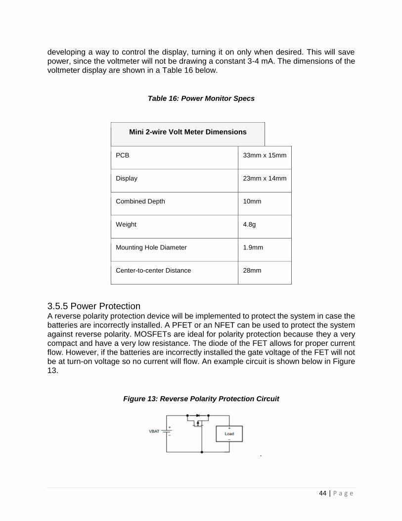
44 | P a g e
developing a way to control the display, turning it on only when desired. This will save power, since the voltmeter will not be drawing a constant 3-4 mA. The dimensions of the voltmeter display are shown in a Table 16 below.
Table 16: Power Monitor Specs
3.5.5 Power Protection A reverse polarity protection device will be implemented to protect the system in case the batteries are incorrectly installed. A PFET or an NFET can be used to protect the system against reverse polarity. MOSFETs are ideal for polarity protection because they a very compact and have a very low resistance. The diode of the FET allows for proper current flow. However, if the batteries are incorrectly installed the gate voltage of the FET will not be at turn-on voltage so no current will flow. An example circuit is shown below in Figure 13.
Figure 13: Reverse Polarity Protection Circuit
Mini 2-wire Volt Meter Dimensions
PCB 33mm x 15mm
Display 23mm x 14mm
Combined Depth 10mm
Weight 4.8g
Mounting Hole Diameter 1.9mm
Center-to-center Distance 28mm

45 | P a g e
The PMOS that will be used is the CSD25310Q2 20 V P-Channel NexFET by Texas Instruments. This MOSFET has a very low resistance at 19.9 mΩ. It has excellent thermal characteristics and is extremely compacts. A complete table of parameters are listed below in Table 17.
Table 17: MOSFET Specs
TA = 25°C TYPICAL VALUE UNIT
VDS Drain-to Source Voltage -20 V Qg Gate Charge Total (-4.5V) 3.6 nC Qgd Gate Charge Gate to Drain 0.5 nC RDS(on)
Drain-to-Source On Resistance VGS = –1.8 V 59.0
mΩ VGS = –2.5 V 27.0 VGS = –4.5 V 19.9
VGS(th) Threshold Voltage -0.85 V
3.6 Microcontroller To control the motor and interface with WiFi/Bluetooth, our team uses a microcontroller with built-in WiFi or Bluetooth modules. The microcontroller is the device that manage the user interface of the smart lock, taking input from the RFID sensor, fingerprint Sensor, keypad, and Android/iPhone application to handle the locking mechanism. Using a microcontroller with a WiFi/Bluetooth module ensures compatibility with these communication protocols with appropriate resources to effectively handle issues regarding the protocol.
Different brands have been researched in order to determine a microcontroller that meets the technical specifications of the smart lock effectively. A high priority is set on compatibility, physical dimensions, and pricing with performance and software development ease of use being the tipping factor.
3.6.1 Arduino Arduino has a wide array of tutorials and pride themselves in their ease of use electronic design. While the Arduino has its own language, it is based on C++ which our team has familiarity with. The primary board considered for Arduino is their Arduino MKR WiFi 1010. The Arduino MKR 1000 WiFi was also considered, but the Arduino MKR WiFi 1010 is a direct improvement of Arduino MKR 1000 WiFi that can be purchased at a cheaper price. This board uses the WiFiNINA library that Arduino provides. Table 18 showcases the technical specifications of the Arduino MKR WiFi 1010 which can be purchased for $34.

46 | P a g e
Table 18: Arduino MKR WiFi 1010 Technical Specifications
Microcontroller SAMD21 Cortex-M0+ 32bit Low Power ARM MCU
Board Power Supply (USB/VIN) 5V
Supported Battery(*) Li-Po Single Cell, 3.7V, 700mAh Minimum
Circuit Operating Voltage 3.3V
Digital I/O Pins 8
PWM Pins 12 (0, 1, 2, 3, 4, 5, 6, 7, 8, 10, A3 - or 18 -, A4 -or 19)
UART 1
SPI 1
I2C 1
I2S 1
Connectivity U-BLOX NINA-W10 Series Low Power 2.4GHz IEEE® 802.11 b/g/n Wi-Fi
Encryption ECC508 Crypto Authentication.
Analog Input Pins 7 (ADC 8/10/12 bit)
Analog Output Pins 1 (DAC 10 bit)
External Interrupts 8 (0, 1, 4, 5, 6, 7, 8, A1 -or 16-, A2 - or 17)
DC Current per I/O Pin 7 mA
Flash Memory 256 KB
SRAM 32 KB
EEPROM No
Clock Speed 32.768 kHz (RTC), 48 MHz
LED_BUILTIN 6
Full-Speed USB Device and Embedded Host
Included
LED_BUILTIN 6
Length 61.5 mm
Width 25 mm
Weight 32 gr.
Arduino has a simple IDE, using a language based on C/C++ that is familiar to the team. To program the Arduino, a bootloader must be obtained or an extra Arduino must be connected to initialize the Arduino to be able to handle software uploaded to it on its Arduino IDE. Its physical dimensions, of 61.5 mm x 25 mm, is the smallest of the examined microcontrollers. These traits are highly desirable for creating a small smart lock allowing greater flexibility for the enclosure of the motors and sensors.

47 | P a g e
However, the optimal sensors for fingerprint and RFID uses UART for low power and small size. With the Arduino MKR WiFi 1010 only having 1 compatible UART port, this is a hard limit for our sensors as it removes a vital feature.
3.6.2 Raspberry Pi Raspberry Pi is known for making small scale computers that has GPIO and USB ports at a low cost. The fact that the Raspberry Pi can run a desktop with Raspbian gives it incredible advantage with GUI as the testing can be done directly on the Raspberry Pi which can serve to make building the phone app easier. The Raspberry Pi 3 Model B is the primary board considered for Raspberry Pi. A Raspberry Pi 3 Model B can be provided by the Robotics Club at UCF and it contains all the necessary features desired for the project. It is difficult to justify upgrading to Raspberry Pi 4 for the price and the idea that the extra features, such as a dual display port, is extraneous for the requirements of the smart lock. Table 19 showcases a list of the technical specifications of the Raspberry Pi 3 Model B which can be purchased for $30.
Table 19: Raspberry Pi 3 Model B Technical Specifications
Raspberry Pi 3 Model B
• 85 x 56 x 17 mm • Quad Core 1.2GHz Broadcom
BCM2837 64bit CPU • 1GB RAM • BCM43438 wireless LAN and
Bluetooth Low Energy (BLE) on board
• 100 Base Ethernet • 40-pin extended GPIO • 4 USB 2 ports • 4 Pole stereo output and composite
video port • Full size HDMI • CSI camera port for connecting a
Raspberry Pi camera • DSI display port for connecting a
Raspberry Pi touchscreen display • Micro SD port for loading your
operating system and storing data • Upgraded switched Micro USB
power source up to 2.5A
The Raspberry Pi has an operating system on it which would allow for more complex software development. The team is not familiar with Raspberry Pi’s software development, but it could prove to be valuable for the Arduino/iPhone application due to its computer like structure. An SD card with the operating system for Raspberry Pi is

48 | P a g e
connected to the board to load its computer like structure. Sensors can be interfaced through USB due to its four available USB ports. Video feed through HDMI is possible, allowing stretch goals to be met.
USB sensors that can be flexibly placed are still much larger than the UART variants. Raspberry Pi 3B also shares with Arduino MKR WiFi 1010 with having only one UART port. Spending significant time learning how to develop software on a Raspberry Pi is also necessary.
3.6.3 Beaglebone Beaglebone makes powerful small-scale computers that have multiple GPIO and UART ports. BeagleBoards have the GUI advantage due to being able to run a Linux desktop. It also comes with both a 3D graphics and floating-point accelerator. This gives a strong incentive to process image or video data with a BeagleBoard. The Beaglebone Black Wireless is the primary board considered for Beaglebone, being the wireless iteration of the standard Beaglebone Black.
The other types of BeagleBoards are too specialized to be considered and not recommended due to the high base price of a BeagleBoard. The high base price of the Beaglebone Black Wireless at $76 means that making the most use of its UART ports and accelerators is expected. Table 20 showcases the technical specifications of the Beaglebone Black Wireless.
Table 20: Beaglebone Black Wireless Technical Specifications
Beaglebone Black Wireless
• 512MB DDR3 RAM
• 4GB 8-bit eMMC on-board flash storage
• 3D graphics accelerator
• NEON floating-point accelerator
• 2x 46 pin headers
• 2x PRU 32-bit microcontrollers
• USB client for power & communications
• USB host
• 802.11b/g/n and Bluetooth 4.1 plus BLE
• HDMI
• 86.36 x 54.61 mm
The Beaglebone Black Wireless is the most powerful microcontroller considered. It has six UART ports which easily allows the smallest sensors to connect while giving room for other potential sensors. Using HDMI with a graphics accelerator can provide a stable video feed. Being able to handle real-time services makes Beaglebone Black Wireless most optimal choice, of the considered options, if a video feed is added.

49 | P a g e
While it is possible to flash a graphical Debian distribution onto the Beaglebone Black Wireless, it is more effective to use the Stretch IoT image to fulfill the low power requirement. If care is not taken to overwork the Beaglebone Black Wireless, it may easily draw too much power with its processing.
The Beaglebone Black Wireless only has one USB 2.0 port which limits its potential for USB sensors. It also comes at a hefty price of $76 being the most expensive option.
3.6.4 Texas Instruments Texas Instruments has the lowest level software development for their launchpads. This means that their launchpads have the most control over electrical design which is made clear with how space for oscillators can be soldered on and the frequent usage of jumpers to connect pins together. Orientation of these jumpers can even adjust the style of UART that the launchpad uses from software to hardware. As such, a plethora of electrical design specifications are available for the Texas Instruments Launchpads.
Due to this low-level design, software development may prove challenging due to the increased complexity needed for software development. The primary IDE used to develop software on a Texas Instruments launchpad is through Code Composer Studio. The Arduino development alternative, Energia, is not compatible for the boards discussed so software development would need to be done in Code Composer Studio. The code is developed in C and has a comprehensive debugging interface that allows developers to check the state of each register. This means that while Code Composer Studio may prove to be most complicated software development platform of the brands considered, it is able to debug electrical issues that other platforms would not be able to comprehend.
The TI LAUNCHXL-CC2650 is the primary board considered for Texas Instruments. While there are multiple other Wi-Fi launchpads, this is in a family of launchpads with Bluetooth embedded within the launchpad as well. Table 21 showcases an outline of the features provided by the TI LAUNCHXL-CC2650. A strong competitor for the TI LAUNCHXL-CC2650 is the TI LAUNCHXL-CC2640R2F due to its inclusion of nonvolatile memory which can prove useful for a temporary storage of logs.
Table 21: TI LAUNCHXL-CC2650 Technical Specifications
• $24
• Microcontroller o Powerful ARM® Cortex®-M3 o EEMBC CoreMark® Score: 142 o Up to 48-MHz Clock Speed o 128KB of In-System Programmable Flash o 8KB of SRAM for Cache o 20KB of Ultralow-Leakage SRAM o 2-Pin cJTAG and JTAG Debugging o Supports Over-The-Air Upgrade (OTA)
Ultralow-Power Sensor Controller

50 | P a g e
o Can Run Autonomous From the Rest of the System o 16-Bit Architecture o 2KB of Ultralow-Leakage SRAM for Code and Data
• Efficient Code Size Architecture, Placing Drivers, Bluetooth® Low Energy Controller, IEEE 802.15.4 MAC, and Bootloader in ROM
• RoHS-Compliant Packages o 4-mm × 4-mm RSM VQFN32 (10 GPIOs) o 5-mm × 5-mm RHB VQFN32 (15 GPIOs) o 7-mm × 7-mm RGZ VQFN48 (31 GPIOs)
• Peripherals o All Digital Peripheral Pins Can Be Routed to Any GPIO o Four General-Purpose Timer Modules
(Eight 16-Bit or Four 32-Bit Timers, PWM Each) o 12-Bit ADC, 200-ksamples/s, 8-Channel Analog MUX o Continuous Time Comparator o Ultralow-Power Analog Comparator o Programmable Current Source o UART o 2× SSI (SPI, MICROWIRE, TI) o I2C o I2S o Real-Time Clock (RTC) o AES-128 Security Module o True Random Number Generator (TRNG) o 10, 15, or 31 GPIOs, Depending on Package Option o Support for Eight Capacitive-Sensing Buttons o Integrated Temperature Sensor
• External System o On-Chip internal DC-DC Converter o Seamless Integration With the SimpleLink™ CC2590 and CC2592
Range Extenders • Low Power
o Wide Supply Voltage Range
• Normal Operation: 1.8 to 3.8 V
• External Regulator Mode: 1.7 to 1.95 V o Active-Mode RX: 5.9 mA o Active-Mode TX at 0 dBm: 6.1 mA o Active-Mode TX at +5 dBm: 9.1 mA o Active-Mode MCU: 61 µA/MHz o Active-Mode MCU: 48.5 CoreMark/mA o Active-Mode Sensor Controller: 8.2 µA/MHz o Standby: 1 µA (RTC Running and RAM/CPU Retention) o Shutdown: 100 nA (Wake Up on External Events)
• RF Section o 2.4-GHz RF Transceiver Compatible With Bluetooth Low Energy (BLE)
4.2 Specification and IEEE 802.15.4 PHY and MAC

51 | P a g e
o Excellent Receiver Sensitivity (–97 dBm for BLE and –100 dBm for 802.15.4), Selectivity, and Blocking Performance
o Link budget of 102 dB/105 dB (BLE/802.15.4) o Programmable Output Power up to +5 dBm o Single-Ended or Differential RF Interface o Suitable for Systems Targeting Compliance With Worldwide Radio
Frequency Regulations
• ETSI EN 300 328 (Europe)
• EN 300 440 Class 2 (Europe)
• FCC CFR47 Part 15 (US)
• ARIB STD-T66 (Japan) • Tools and Development Environment
o Full-Feature and Low-Cost Development Kits o Multiple Reference Designs for Different RF Configurations o Packet Sniffer PC Software o Sensor Controller Studio o SmartRF™ Studio o SmartRF Flash Programmer 2 o IAR Embedded Workbench® for ARM o Code Composer Studio™
Texas Instruments is the cheapest option at $24. It has well documented electrical specifications and is capable of consuming little power. On standby the TI LAUNCH-CC2650 runs with only 1 µA. plethora of jumper cables also gives the TI LAUNCH-CC2650 an edge on electrical debugging. The team is familiar with Texas Instruments launchpads.
Even with the familiarity of launchpads, there is a steep learning curve requiring a lot of time to learning the protocol as well as using the extended features of the launchpad. TI Launchpads are capable of being built on a coding platform similar to Arduino, but this particular launchpad requires Code Composer Studio. As an IDE, Code Composer Studio is very low level due its codebase being C.
It only has one UART port which like the Arduino MKR WiFi 1010, limits the usage of multiple sensors. This has the largest form factor of all microcontrollers considered.
3.7 Web Server Software
The voice user interface that will require research in order for implementation is the Alexa Voice Service feature. This will give the user another method of accessing their home and it gives the product a friendly human-computer interaction. An understanding of the Alexa Presentation Language (APL) will be required as well as the intuition to think of situational scenarios to program into the software to give the user a convenient experience. This aspect also pushes the product to be an excellent addition to users that are aiming to have a full smart home experience. This is considered to be cloud-based
52 | P a g e
intelligence and it will rely on the wireless features of the device. In the following section the developmental knowledge for the Alexa software will be explored in further detail including the steps and ideas required to add an efficient addition to the product.
3.7.1 Alexa Voice Service
The Alexa Voice Service will provide a natural language processing (NLP) engine to the product that can be used to enhance the user experience. Phrases need to be designated to be commands in order to operate the system, and this will be programmed into the device within the software design. There are four design patterns that need to be focused on and they are adaptability, personality, availability and relatability. A USB microphone will be required for the product in order to have this feature be a possibility. An SD card or some sort of memory retention device will also be required to have for this feature and installed into the product. Other than this, the setup is simple and just requires simple programming logic to have the design properly installed and ready for use.
3.8 Circuitry Housing Once the circuit is completed, it will require casing to prevent short circuiting and other outside disturbances that would cause or Smart-Lock to malfunction. The options we have are Repurposing a casing from a similar project, 3D printing a unique case for this project, or Resin molding.
3.8.1 Resin
This one of our option for the housing of our circuit. Alumite is a brand of resin that we would use for setting resin molding. Setting resin molding is a simple process and can yield a sturdy case that is as hard as plastic. Alumite is a resin that is composed of two chemicals, two-part resin, and when these chemicals are mixed a mold is created. The first step of making the resin mold is to create a prototype mold because resin is generally used to create duplicate objects that already exist. This parameter would cause us problems because our Smart-Lock is being created from scratch. Although, the design for the Smart-Lock casing we are looking to create are simple shapes so we could possibly craft these prototypes from clay if we are careful. Once this completed the final step would be to pour the resin chemicals into the molds so that they can take shape. we could even add color to the resin so that the molds would appear more stylish or creative to the users. The drawback of this is that it would require time and money to craft and acquire these clay models.
3.8.2 Repurposing a Casing Another option at our disposal is to repurpose an existing casing from a Smart Lock that is already available for purpose. As you can see in the Industrial Products subsection of our Research section, there are at least three Smart-Locks available that we could

53 | P a g e
acquire and dismantle the existing circuitry and motor inside and place our own circuit and motor inside. The components that would take the input to open the door such as the Fingerprint Sensor, RFID sensor and Keypad would be housed on the exterior of the door meaning that the casing that we would repurpose would be different than the casing than we repurpose for our microcontroller board. Ideally, we would house all three devices in the same casing on the exterior of the home for user ease. Finding a casing that can house all three of these devices should not be difficult, but it may not fit our device perfectly. We may also have similar problems with our microcontroller board because the screw holes for the case may not line up with the hole on the board or it may not fit without the use of tools to mold the existing case. There is also the legal issue that we could be leaving ourselves open to if we use there casing and violate any of their patents.
3.8.3 3D Printing The final option is 3D printing a unique case for our project. This is an option available to the general public to public in recent years. Our group has access to an 3D printer via the UCF Robotics club. The benefit of this that that we would design this casing to fit our board and exterior sensor components perfectly so that there are no issues when we begin attaching everything to the casings as oppose to if we repurposed the casing of an existing Smart-Lock. The drawback that each casing we print takes an extended period of time so that can put us behind schedule if we have to print multiple case different protypes. Another drawback is that each casing that we print requires a specific material and which depending on the material we choose can be costly and cause us to go over our budget. Although these drawbacks are prevalent, we believe this option is the best for our project.
4 Standards & Constraints This section describes the standards and constraints that are associated with this project. When it comes to engineering standards this these are set standards that have been developed by the industry. These standards are established normality’s that are requirements placed on specific designs. Standards are developed into a document that creates a uniform criteria, process, practice, or method to promote a high degree of excellence uniform across related products and practices. Codes are also developed in order to set rules and specifications for design, fabrication, instillation, and inspection methods. These codes are upheld by legal jurisdiction. Codes are approved by the various levels of government and carry the weight of the law. Codes are set to protect the public safety.
54 | P a g e
Engineering constraints are conditions that are placed upon a project or processes in order for it to perform in a successful manner. Constraints confine the developer to choosing specific components and developing the project in a certain manner in order for proper functionality. Constraints can be decided from the customer, environment, size, or cost.
4.1 Standards Certain standards are expected to be met upon the creation of a smart lock. Security standard include ANSI/BHMA standards for electrified locking devices. Digital communication standards, alongside the IEE 802 standards for Bluetooth and WiFi, should be met to satisfy the need of a phone application as a controller for the smart lock.
4.1.1 IEEE 802.15.1 Bluetooth & Bluetooth SIG Standards In order to maintain a low power smart lock, the Bluetooth module will be limited to a class 3 device which can only run at a maximum of 1mW of power, typically running at much lower wattages. Class 2 Bluetooth should only be considered if there is a need to connect to the smart lock beyond a meter. This should not be necessary due to the usage of Wi-Fi alongside Bluetooth.
The HCI is embedded within the microcontroller with the onboard Bluetooth determining the version, e.g. Raspberry Pi 3B uses Bluetooth 4.1. No design changes are planned for altering the Bluetooth’s functionality on the microcontroller; thus, a Bluetooth SIG Certification may be obtained without testing. This can be achieved for the Bluetooth qualification.
The Beaglebone Black Wireless board uses Bluetooth 4.1 with BLE. As such, it has
L2CAP, GAP, ATT, GATT, SM, PHY, and LL layers. L2CAP is the logical link control and
adaptation protocol. It provides channel multiplexing, segmentation and reassembly
(SAR), per-channel flow control, and error control. Figure 14 outlines the architectural
block diagram of L2CAP from Bluetooth.

55 | P a g e
Figure 14: L2CAP Architectural Block Diagram
Reprinted with permission from Bluetooth
GAP is the generic access profile that defines the generic procedures related to the
discovery of Bluetooth devices. It introduces definitions, recommendations, and common
requirements related to modes and access procedures. ATT is the attribute protocol that
discovers and writes attributes for peer devices while GATT is the generic attributes
protocol that discovers, reads, writes, notifies characteristics, and configuring the
broadcasted characteristics. SM is the security manager that defines the protocol and
behavior for managing pairing, authentication, and encryption between LE-only or
BR/EDR/LE devices. SM uses key distribution which means that each device generates
and controls the keys it distributes without being affected by other devices. The three
phases to paring that SM handles is the pairing feature exchange, short/long-term key
generation, and transportation of the specific key. Figure 15 outlines the three phases of
the pairing procedure.

56 | P a g e
Figure 15: LE Pairing Phases
Reprinted with permission from Bluetooth
PHY refers to the physical layer of Bluetooth LE. It operates within the 2.4 GHz Industrial
Scientific Medical (ISM) band. It uses two modulation schemes with that can either handle
1 Msym/s or 2 Msym/s. Plans for implementing LE Coded PHY for the 2 Msym/s depends
on the performance of Bluetooth communication. Since 1 Msym/s is provided by default
by Bluetooth LE, unless there is a significant latency issue related to limitations of
Bluetooth throughput, LE Coded PHY will not be implemented due to an additional layer
of complexity to the design. LL refers to the link layer of Bluetooth LE. The link layer
functions as a state machine that can only allow one state to be active at a time. All the
states of Bluetooth LE are standby, advertising, scanning, initiating, connection, and
synchronization. Figure 16 displays the state machine of the link layer for Bluetooth LE.

57 | P a g e
Figure 16: Bluetooth LE Link Layer State Machine
Reprinted with permission from Bluetooth
Low-level design changes will not be made to Bluetooth to allow the smart lock to
maintain its Bluetooth SIG Certification unless necessary. The main factor that could
possibly be changed is the optional LE Coded PHY, but this is highly unlikely due to the
lack of innate compatibility of the Beaglebone Black Wireless and LE Coded PHY. Even
without any design changes, understanding the pairing mechanism is crucial for
debugging connection issues that may arise for Bluetooth communication.
4.1.2 IEEE 802.11 The IEEE Standards for Wireless connections (WiFi) is focused on enhancements to existing medium access controls and physical layer functions. This is used for portable personal devices to have access to a WiFi connection, which is necessary for smart lock application. The smartlock is going to need wireless capabilities in order to be compatible with a user’s smart phone.
4.1.3 Communication Standards The Communication Standards involves the ability for two or more pieces of a communications system to send/receive information through a physical quantity. This is the parent standard to the IEEE 802.11 and IEEE 802.15.1, so it is an integral standard

58 | P a g e
for this project. This standard stands as an umbrella standard that is based on the physical and the data link layer (which includes the LLC and MAC sublayers.)
4.1.4 ANSI/BHMA A156.25-2018 This is the standard for Electrified Locking Devices.
The BHMA expects electrical locks to comply to all building safety and performance requirements and to be sustainable over its verified durability. Various performance requirements are expected including the reliability of operation, durability, and electrical integrity of the smart lock.
The smart lock should be capable of functioning when under/over voltage. It should also be able to withstand at least 10,000 door slam cycles and stay fully functional. The smart lock should also be able to handle a wide range of alternating temperatures.
The electrical specifications follow some of the tests in UL-1034 Standard for Burglary-Resistant Electrical Locking Mechanisms. As such, the smart lock can be rated based on dynamic strength, static strength, and endurance based on cycles. To pass these tests, the smart lock must have a minimum of 500 pound-force of static strength, 33 foot-pound-force of dynamic strength, and can withstand 100,000 cycles. Corrosion protection, over-current protection, humidity, strain relief, and production line ground continuity are all examples of electrical tests for the BHMA Certification.
With this in mind, certain tests must be designed to prepare for the BHMA Certification:
• Automated door slam cycle tester
• Undervoltage circuit test
• Overvoltage circuit test
• Static stress test
• Dynamic stress test
• Humidity test
• Over-current protection test
• Ground continuity test
• Temperature test
This creates new expectations alongside our design. A machine to slam a door with a smart lock attached to it should be designed. A humidity sensor will be needed to determine a statistic for the humidity test. High current protection, e.g. surge protector, is necessary. New connectors should be designed to fulfill the undervoltage and overvoltage tests.
4.1.5 Advanced Encryption Standard The AES is an encryption specification for electronic data. It was originally called Rijndael from the AES competition’s first place competitor who developed a standardized cipher. Due to the need for encryption to strengthen PIN security, this is amongst the fastest of standardized ciphers that is considered secure. It is useful to use this cipher to secure

59 | P a g e
passwords saved into the smart lock database. Figure 17 outlines the algorithm used to create the ciphertext from plaintext.
Figure 17: Advanced Encryption Standard Algorithm
Fulfilling this standard requires 9, 11, or 13 rounds of key expansion with an initial round key addition. The rounds will substitute bytes by using a lookup table, shift the last three rows of the state cyclically, linearly mixing the operation of the columns by combining the four bytes in each column, and then adding a round key. After the rounds are complete, the bytes are substituted, a round without the linear mixing is done to finish the ciphertext.
4.1.6 ISO 9564 This is the international standard for financial PINs. While this is not applicable to a smart lock for household security, it serves as a good guideline for what things to consider for ensuring security. Thus, while this standard may not be fulfilled completely, many ideas will be taken from the standard for stronger PIN security.
Due to PINs being the least secure innate form of a password, the PIN should be encrypted in an unpredictable way. This standard also mandates that a stored encrypted PIN must be protected from substitution. While replacing a PIN is a feature expected by users, this can be subverted by using the other forms of authentication to prove the user’s identity.
The PIN entry device is also subjected to this standard. The standard mandates that the PIN entry device must only allow numeric characters to be entered. This means that if any kind of letters that are planned to be recognized by the keypad are not to be recognized. This relinquishes this standard from passwords that uses alphanumeric

60 | P a g e
characters since letters don’t exist in a PIN. It also states that the layout of the keypad should be unambiguous with enter and clear buttons. If this is not feasible, having the phone explicitly state to press a special character such as * or # to finish the PIN can suffice in terms of clarity.
4.1.7 IPC-2221 PCB Standard The IPC-2221 is a design standard for printed circuit boards and it’s made by the
Institute for Interconnecting and Packaging Electronic Circuits. The specific name of this
standard is “Generic Standard on Printed Board Design.” This tells one that when
building a PCB they need to consider every portion of the board itself, including the
trace width and spacing, pad and hole sizes, and hole spacing. The size of a board
gives off its own unique amount of resistance.
The standard requires identification of the class of the product and an understanding of
the complexity of the board required. This standard also gives different boards different
standards depending on the material used to make up these boards. The performance
classes also help distinguish between the complexity levels of products. For the product
we are designing it is to be a Class 1 General Electronic Product design. This means
that the product contains general hardware, some computer and computer peripherals.
These products tend to not be affected by any imperfections on the surface level of the
PCB.
In order for a board layout to be up to standard all mandatory considerations must be
taken care of including meeting minimum etched features, minimum plating thickness,
board shape, the coating and marking requirements and meeting the requirements in
testing locations. The design for the PCB board also needs to go through rigorous
testing to affirm that the design will not be a hazard to users. The design must also be
evaluated and have all of the current and voltage levels checked. This is due to the fact
that the current and voltage levels will be used to determine the gap size in between the
holes and routes in the design of the PCB. The design must also go through at least
three tests to pass what is known as the Vectorless Test. These tests are the Analog
Junction Test, RF Induction Test, and Capacitive Coupling Test. The Analog Junction
Test is a DC current measurement test that checks different pin pairs using protection
diodes. The RF Induction Test is when magnetic induction is used to check for any
issues with the device when using the PCB’s protection diodes. This checks for broken
wires, damaged devices or solder opens in used paths. The Capacitive Coupling Test is
used to test the pins of the device by checking the presence of metallic lead frames of
the device.
4.2 Constraints The following are a list of different types of constraints that will guide the development structure of this project. Included are a mix of physical constraints, power constraints, as

61 | P a g e
well as experiential and economic constraints. These constraints will be further discussed in greater detail in the following subsections. The constraints are physically possible and will not impede the progress in the development of the project.
4.2.1 Minimalistic Dimension Constraints The goal of our dimension constraints is to be about the size of the August Smart Lock, 3rd Gen. The dimensions for this are about 1.6 x 2.6 x 4.8 inches, which gives us a small, yet efficient design for our project. Not included in the dimension constraints is the keypad, which could be added as an external feature to the smart lock. The goal for the size of the smart lock is to be minimal, but still maintain the intended features.
Ideal technology is to be as minimalistic as possible, but still have as many features as possible. This is the goal of our project, as we are focusing on giving our smart lock as many features as possible to match the competitors. The goal for a smaller smart lock also revolves around the fact that it can’t cover too much space on the door for convenience and practicality purposes. It must also be acknowledged that the lock itself cannot be too small because we will only have access to cheaper technology.
4.2.2 Low Power Constraints The low power constraints are going to revolve around the abilities of our batteries of choice and how well our divider can function. We are still aiming for minimal power consumption in order to make this an efficient product, otherwise it will be inconvenient to constantly change the batteries. We will also need a large enough voltage to power through the motherboard, the RFID reader subsystem, the fingerprint sensor subsystem, the motor subsystem, the keypad subsystem, and the Alexa feature subsystem.
4.2.3 Time Constraints The time constraints of the project are brought upon us by the fact that we are limited to two semesters to set up and complete this project with a working prototype. This adds a limit to the number of features that can be added to the project. Due to the time constraints we had to add tier goals and base the focus of the features on the available time. There is still enough time to make tier one and two goals easily possible, but the third-tier goals are more difficult to achieve. The members of the group also have other responsibilities, such as other jobs and classes to limit the amount of time that is available to be spent upon this project.
4.2.4 Memory Constraints Memory constraints limit the number of users that can be saved within the Bluetooth chip and other devices connected to the product. The choice of the Bluetooth chip limits the memory of it and limits the number of users that can be saved, this is due to the fact that it lacks a RAM memory. Although the other choices had RAM and ROM availability, the

62 | P a g e
better option remained the chosen Bluetooth device. Since we are focusing on a cost-effective design, this has to remove our reliance on the internal storage of our device.
4.2.5 Experience Constraints We lack hands-on experience largely due to the fact that we are students and lack past knowledge that could assist us with picking the ideal pieces for this project. This project is to help us build these skills that can help us be successful engineers upon graduation. The constraint that the lack of experience brings us can limit the results of our project, as well as give us unintended results. This could cause difficulties in the future if certain steps are taken carelessly.
4.2.6 Economic Constraints Economic constraints are limited to a budget of about $200, due to the fact that we are undergraduate level students with a limited economic reach. Due to the fact that we were unable to obtain sponsors, we are also further limited on our budget. This limit is also partially based on the price for several different competitor’s products. The reasoning behind basing our prices around the competition is in order to bring an appeal towards the smart lock product. Although having a budget can bring us towards making an affordable product, it also limits the power and processing power of the system. This partially shifts the focus on some part purchases to be on durability, price and then power.
4.2.7 Environmental Constraints Environmental constraints are defined as the surroundings, and conditions that impact the performance of a design. Considering the Keyless Entry product, the outside environment indeed will impact the product itself. There will be components that will be mounted to the outside of the door that will be susceptible to the outside environment; rain, heat, wind, possible obstructions meeting the device, cold temperatures, and the presence and absence of light.
The components that will be installed on the outside of the door include but are not limited to: keypad, fingerprint sensor, RFID, and battery holder. There will be casing that will enclose the battery holder, RFID, and any PCB or circuitry that coincides with these components. Therefore, the encasing will need to be design so that it can withstand the sentimental impacts. Also, the keypad and fingerprint sensor will likely need to be waterproof or water resistant.
4.2.8 Social Constraints Social constraints are defined as the social impact that the product or design has. With the Keyless Entry product, the aim is to create an ease of use smart lock that will allow the user simple and easy access to their home. Also, the user will have multiple ease in order to access their home so they will experience a peace of mind that they will have to exert very little effort to lock and unlock their door. There is also a sense of security

63 | P a g e
associated with the Keyless Entry product, there will be sensors that react if a break in is attempted triggering an alert to be sent to the user and/or an alarm to sound.
4.2.9 Political Constraints Political constraints are defined as any impact that the product or design has that impacts any government, or political infrastructure or construct. The Keyless Entry project is designed and developed through the educational system and therefore is strictly for educational purposes. Furthermore, there are no real political constraints associated with this project.
4.2.10 Ethical Constraints Ethical constraints can be defined as anything present in the system or design that violates the IEEE code of ethics. There are few ethical constraints associated with this project. These constraints involve the security of the user. The door lock should uphold the IEEE door standards.
A fundamental constraint from the code of ethics is the safety, health and welfare of the public. This pertains to how safe our design is and how the product can affect the user. Some elements that need to be focused on for the design of this project are overcurrent and overvoltage. These issues can be avoided by having a proper circuit design and thoroughly testing the product in different scenarios and testing all of the features while measuring the values. There can also be an overcurrent when the product is exposed to lower temperatures, so there can be a warning to keep owners from exposing the product to temperatures outside the operating temperatures.
In order to remain within the ethical constraints, the description of the product must also be objective and truthful and avoid any conduct that may bring discredit upon the profession. To maintain this, we must simply post and advertise the details that have been tested and proven entirely true for this product. There must not be any features that are falsely mentioned or that have not been tested properly for failure. This will remove confidence within the product and discredit the system that we are operating under. The statements that will be made of this product must also remain testable and not based on opinions or subjective bias.
The environmental constraint also coincides with the ethical constraint, and this was explained in further detail in the environmental constraints section. The product must be within all of the previous ethical constraints as well as the other ethical constraints included within the IEEE standards. Under no circumstances must any ethical sanctions be pursued.

64 | P a g e
4.2.11 Manufacturability Constraints Manufacturability constraints are guidelines and specific requirements that make the product easy to develop and be reproduced. The Keyless Entry product should be designed in a way that it can be produced with as few components as possible. This will ensure for efficiency in manufacturing labor and device maintenance.
4.2.12 Sustainability Constraints Sustainability constraints refer to the engineered product or designs ability to perform reliably for an extensive period of time. It should maintain normal operating conditions. For the Keyless Entry product, it should be able to constantly adhere to the needs of the user without fault, since the device stands in the way of the user accessing their home. Also, the device should be able to operate for a long duration without having the need to replace its batteries.
4.2.13 Health and Safety Constraints Health and safety constraints refers to the products ability to be constructed and operated without posing any immediate threat to the user. The Keyless Entry should be designed so that the user will not come in contact with any electrical shock or disturbance while changing the devices batteries. The device should also be constructed with caution, not to cause any harm to the constructor. Therefore, safety measures should be taken by the builder and tester.
5 Hardware and Software Design The following section will describe how the hardware and software will be designed for proper functionality of the system. This process is one of the more important parts of the project because it sets up the general framework to properly execute smooth prototyping of the design. The presented design that will be presented is liable to change or be revised due to possible occurrences of problems or obstacles that might present themselves.

65 | P a g e
In this section, we also briefly summarize our decisions as it pertains to the hardware components that we have chosen to use for this project as well as the coding environment that we are using we are using for the software. The hardware components were chosen by various factors such as price and component specifications. The price was always a big factor when choosing components because low cost is one of our goals for this project, but because the component is better in that since does not meant that we are going to choose it. That is when the component specifications, all of which were discussed in our research section, factor into the choice because each part chosen has a specific characteristic that makes it the ideal choice for our project. The Coding environment however was chosen based on the which environment would best be able to support the Android Application as well as how comfortable we were coding on that environment.
5.1 Block Diagrams The subsequent subsections contain block diagrams that demonstrate the flow of functionality of different aspects of the Keyless Entry system. It will begin with an overall system architecture and will be followed by more in depth detailed diagrams of each subsystem of the unit.
5.1.1 Overall System Architecture Figure 18: Overall System Diagram, shown below illustrates the basic system architecture of the Keyless Entry device. The device requires user input and will respond based on what signals it receives. It has six key components that work together to provide an interface that is desired. The user will be able to unlock the lock with at least four different ways. These different inlock methods consist of Bluetooth communication, keypad, RFID, and fingerprint scanner. Other methods of unlocking may be introduced if progress is ahead of schedule. There will be a mobile application that will connect the microcontroller wireless through Bluetooth. The user will also have an RFID chip that will communicate with the microcontroller through an RFID processor. Once the MCU processes the input signal from either of the select unlock methods it will send a signal that will power the motor and rotate it a desired radial degree and unlock the door. Once the door is unlocked a timer will start and automatically lock the door after a certain period of time. I push to exit button will be considered adding to the design so that any user can exit without needing to have access to the application or have an RFID card available to them. Any further additions that may be made will be added to the overall system architecture block diagram.

66 | P a g e
Figure 18: Overall System Diagram
5.1.2 Power Distribution Figure 19: Power Distribution System, shown below is a diagram of the basic design of the power supply and how power will be distributed amongst the system. This provides a very basic concept of the distribution of power from the source. Either signal reduction or even signal amplification will most likely be implemented to receive a proper signal from the power source and its preceding connections. There will be voltage regulation and amplification implemented in order to properly power the microcontroller and motor. There will also be LEDs and sensors implemented in the design but since these are very low voltage and low current components, they will most likely be powered directly from the microcontroller. There may be additional changes needed to be made to the power distribution system if components are further added, if this occurs the necessary changes will be made to the power distribution diagram will be made.

67 | P a g e
Figure 19: Power Distribution System
5.1.3 Bluetooth Communication
Due to the high chances that Bluetooth will not have any low-level design changes, its
communication will be straightforward. The only complication is how a new Bluetooth
link is setup. Sensors will intentionally be avoided to remove dependency of Bluetooth
on the peripherals of the smart lock. It is more likely that the microcontroller shall
randomly send a plaintext to the phone for it to verify the integrity of the Bluetooth link.
While this does introduce the vulnerability that any user may connect to the smart lock
without being logged of their actions, the security of the smart lock itself is maintained
by encryption and decryption methods that are available only through the phone app
and the microcontroller. Thus, any changes to the smart lock through Bluetooth can only
be feasibly accomplished through the phone app. Figure 20 shows the process and
protocols used to protect the authenticity of the Bluetooth communication.
Figure 20: Bluetooth Communication Design

68 | P a g e
5.1.4 RFID Communication
Since there is no method to place encryption and decryption on an RFID tag, it is limited
by the need of other authentication methods to verify the authenticity of the user. The
main form of security is preventing anonymous individuals from finding valid RFIDs from
access to the smart lock database alone. Figure 21 displays the basic security measures
used for the RFID.
Figure 21: RFID Security Measures
If an RFID has been shown to work as an authentication method, it is to be secured by
the user personally to the same degree as a key to the home. On the other hand,
preventing users from creating a key from the database essentially protects the smart
lock from the case that an anonymous individual does not know a valid RFID tag. As
such, an RFID can be encrypted/decrypted on the microcontroller end while the user
personally secures the RFID tag. If an RFID tag is lost, the user can disassociate the

69 | P a g e
RFID to their user ID on the phone app, eliminating the threat of a lost RFID tag with
minimal threat. The lost RFID will be logged in the database and can be checked with a
new RFID tag to ensure uniqueness.
5.1.5 User Interface Figure 22: User Interface System Diagram, that is shown below illustrates how the user will interact with the Keyless Entry system. The user interface will be devolved through an Android application. On the main menu, or home screen, of the application the user will be able to select be able to see the history of the door, lock/unlock cycle with time stamp, and will be able to unlock and lock the door. These functionalities will be available to be accessed from anywhere. You will always know the state of the lock. The team plans on making the application so that many users can access the Keyless Entry device on one main hub. There will be a setting that you can enable so that you will get notifications every time the lock is operated, even if it is manually operated. Also, the team is considering adding a preference where guest users will be able to access the lock/unlock functionality.
User Interface Architecture
Figure 22: User Interface System Diagram
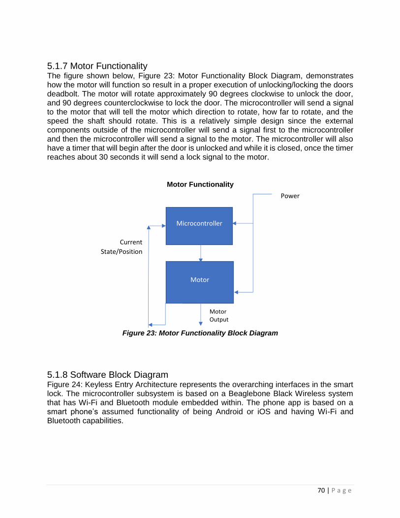
70 | P a g e
5.1.7 Motor Functionality The figure shown below, Figure 23: Motor Functionality Block Diagram, demonstrates how the motor will function so result in a proper execution of unlocking/locking the doors deadbolt. The motor will rotate approximately 90 degrees clockwise to unlock the door, and 90 degrees counterclockwise to lock the door. The microcontroller will send a signal to the motor that will tell the motor which direction to rotate, how far to rotate, and the speed the shaft should rotate. This is a relatively simple design since the external components outside of the microcontroller will send a signal first to the microcontroller and then the microcontroller will send a signal to the motor. The microcontroller will also have a timer that will begin after the door is unlocked and while it is closed, once the timer reaches about 30 seconds it will send a lock signal to the motor.
Motor Functionality
Figure 23: Motor Functionality Block Diagram
5.1.8 Software Block Diagram Figure 24: Keyless Entry Architecture represents the overarching interfaces in the smart lock. The microcontroller subsystem is based on a Beaglebone Black Wireless system that has Wi-Fi and Bluetooth module embedded within. The phone app is based on a smart phone’s assumed functionality of being Android or iOS and having Wi-Fi and Bluetooth capabilities.
Microcontroller
Motor
Power
Motor Output
Current
State/Position

71 | P a g e
Figure 24: Keyless Entry Architecture
The microcontroller has three major considerations for software: its Debian operating system, the Wi-Fi and Bluetooth communication, and the Hardware Interface. The Debian operating system is an important step to start setting up the development of the smart lock. It determines the compatibility with IDEs which ends up isolating which programming languages to work with. As of now, the options are JavaScript or C/C++.
The Wi-Fi and Bluetooth communication are significant for setting up the microcontroller. The setup begins with Wi-Fi or Bluetooth, at least one must function to setup the smart lock. As such, the smart phone app must have a reliable Wi-Fi and Bluetooth link with the microcontroller. One way to guarantee a stable link is to design the link to be connection-oriented. This is useful for a household that does not house many individuals. The primary weakness to a connection-oriented link is its bandwidth which fails to handle large traffic effectively.
The hardware interface contains the core functionality of the smart lock. Connections to the sensors will be made with digital pins and serial UART. The motors will be activated by PWM pins. A serial UART interface needs to be developed to connect the sensors to the microcontroller. The PWM is controlled by both the digital pin logic and the sensor logic. The sensors logic is the primary service given to the phone app. When certain flags are met by the sensors, the digital pins will act to carry out tasks like lighting up LEDs.

72 | P a g e
The sensor logic keeps flags for the methods of authentication and the PWM responds based on the settings made by the phone app.
The phone app also has three major considerations for software: The Android operating system or iOS, Wi-Fi and Bluetooth communication, and the User Interface. The Android operating system has verified support for the Beaglebone Black Wireless. Project Rowboat, Linaro, and Sitara all support Arduino for the Beaglebone Black Wireless due to its ARM processor. It is also possible to interface with iOS with BBConsole which opens a terminal that can be used in iOS devices.
The user interface has security and quality of life settings that allow the user to control the smart lock through their phone. Every event that is logged from the smart lock is updated on the database and can be viewed through the phone app. Some of these events are high-level which gives the phone notifications. These notifications are specific to each user within their user settings. Every form of authentication, including the phone itself through Wi-Fi/Bluetooth is stored within the database for each user. Each type of authentication begins within the app and communicates with the microcontroller to enroll the sensor data to the user. This allows the phone app to be the middle ground that manages the security of which users can be registered for the smart lock.
The QOL settings focus on ease of use while giving the user control over its security. The knock pattern is a form of authentication that can allow you to open the door. The knocking can also notify users that someone is at their door by sending a notification to their phone. The automatic (un)locking allows the user to unlock and relock their door to enter the facility easily without interacting with the door. Unlocking can occur upon a combination of RFID and Wi-Fi/Bluetooth which serves as authentication that can occur from afar.
Figure 25 represents the preliminary design of the sensor logic block within the hardware interface. The sensor logic class is the controller which provides the user ID to the sensors and initiates the enrollment process of each sensor. The enroll function within the sensor logic class needs an integer which serves as an indicator of which class of sensors the user should enroll to and a string that represents the user ID. The resulting string will be a ciphertext to be stored within the database at the index corresponding to the enrolled authentication method. The authenticity check will be called by the phone app to update the number of verified authentications for a user. This number is a condition for the unlocking mechanism for the smart lock. Ideally, when the required number of authentications is met, the door will unlock.
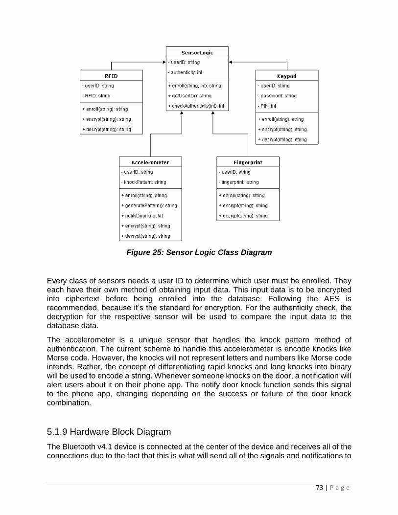
73 | P a g e
Figure 25: Sensor Logic Class Diagram
Every class of sensors needs a user ID to determine which user must be enrolled. They each have their own method of obtaining input data. This input data is to be encrypted into ciphertext before being enrolled into the database. Following the AES is recommended, because it’s the standard for encryption. For the authenticity check, the decryption for the respective sensor will be used to compare the input data to the database data.
The accelerometer is a unique sensor that handles the knock pattern method of authentication. The current scheme to handle this accelerometer is encode knocks like Morse code. However, the knocks will not represent letters and numbers like Morse code intends. Rather, the concept of differentiating rapid knocks and long knocks into binary will be used to encode a string. Whenever someone knocks on the door, a notification will alert users about it on their phone app. The notify door knock function sends this signal to the phone app, changing depending on the success or failure of the door knock combination.
5.1.9 Hardware Block Diagram
The Bluetooth v4.1 device is connected at the center of the device and receives all of the connections due to the fact that this is what will send all of the signals and notifications to

74 | P a g e
the featured devices and receives the connections from the MCU and the portable device that will be used to send commands. It is intended to simply connect the Bluetooth device to just one battery, to receive the 3V connection to power it as well as some of the additional devices. The devices include the fingerprint sensor, the keypad and accelerometer. Then the connection must go through a voltage regulator or a PFET (for reverse polarity protection) before it is connected to the other end of the second battery, which brings the total voltage to 6V. This voltage value will be enough to power the desired motor to use for our smart lock device.
Another benefit of having the Bluetooth device connected in the center of the system for the block diagram is that this connection allows it to monitor the levels of the other devices. This is something that can be added towards the application in the software design. This gives us a reduction in the power required to operate the device and also allows us to have further control on the maintenance aspect of our product. This design also gives the best battery life and protection from internal failure for the product. The devices that have the most important power consumption levels will be the MCU, Bluetooth, motor and the power management (the PFET device.) The focus and ideal situation is for the design to give us the lowest power consumption, since adding wireless capabilities will be the biggest concern for the power and battery longevity of the device. Figure 26: The Block Diagram below of the device with the features connected.
Figure 26: Hardware Block Diagram

75 | P a g e
5.2 Hardware Design This section is where each of the choices for the each of the sensors that will be used as forms of entry for our Smart Lock. The first choice is the microcontroller board we are going to be using to test our Smart-Lock, this is important because this will help determine how we are going to design the PCB for the final form of our project. The Fingerprint sensor and RFID sensor choices are important as well because the factor into the security of our lock. This section also contains a subsection that explains the features that we are using in our Smart Lock.
The following sections discuss the different options of components that were available for use in the Keyless Entry project, the design and reasoning for choosing specific hardware to be used will be discussed. The hardware design of this system is going to focus on reduced power consumption and the efficiency of the circuit. In order to protect our design against reverse polarity we added a PFET in between the connections between the two batteries. This prevents the device from turning on and burning out if the batteries are installed incorrectly. If the batteries are placed properly, then the device is powered and the correct voltage and current goes through the system. To assist with the battery life and longevity of the product, the Bluetooth component can also monitor the battery voltage for low-life indicators, and this will limit the current running through the motor. This process can extend the life of the motor itself and it can be used to communicate back to the user using LED lighting. A regulator can be used to further extend the battery life of the device in order to efficiently operate with the additions of wireless communication.
The circuit design for this product will be created using EAGLE and several libraries will assist us with selecting the correct parts. The software will allow us to be able to simulate the 2D design and assist us with envisioning the 3-dimensional layout of the circuit board. Throughout this section the designs will be shown in parts, but the wires that are shared will have the same names. This also allows us to easily create the layout for the design when we combine all of the separate designs for each of the features. Although additional schematics exist for certain portions of each device that allow them to be operational, the designs used in this section will focus on the portions of the schematics that will be used and connected to each operable portion of the product. The overall schematics can be observed in other sections of this report, but the focus of this section will be the connections that must be made by us for the product. This will also allow an easier method of observation for the testing section of the report. We will need to have a simulated system check prior to the overall/physical product test.

76 | P a g e
5.2.1 Motor Design The motor that will be selected for turning the thumb deadbolt must be capable of operating at a high enough torque and it also must operate with a high degree of accuracy. The following subsections will outline the process of designing the motor and its electrical schematic needed to properly result in correct functionality.
5.2.1.1 Requirements The requirements that were needed for the motor was a main consideration when it came to motor chose for use in the Keyless Entry project. The main requirement that the motor needed to fulfill was having a high enough torque in order to turn the deadbolt properly. The torque required to turn the thumb screw that manually turns the deadbolt from the inside of the door frame is relatively low. Therefore, the group determined the most effective way to attach a motor was to mount it to this thumbscrew in order to ensure that a low torque motor would suffice.
Another requirement of the motor was to operate at a quick speed so that fast unlock/lock cycles could be achieved
5.2.1.2 Stepper Motor The stepper motor being researched by the team is Nema 17 Bipolar. A bipolar stepper motor consists of a single winding per phase. In order to reverse the magnetic pole, the driving circuit must be constructed more complexly. A driver chip can be purchased to accomplish this task, or an h-bridge arrangement can be constructed.
The motor is turned by converting several impulse square waves into a discrete amount of rotation in the shafts position. The frequency of these impulses determines the speed at which the shaft rotates.
The Nema 17 has a holding torque of 1.325 kg-cm per phase. Holding torque is measured by the rotating force required to move a motionless stepper motor shaft out of position. The need for a holding torque this high would be for a design in which the load needs to be held in place.
The Nema motor requires a supplied voltage of 2.9 V and pulls 0.7 A per phase. These ratings prove respectable, due to the low power consumption. Tables of all of the motor’s specifications are provided in Table 22 and Table 23.

77 | P a g e
Table 22: Stepper Physical Specs
Table 23: Stepper Electrical Specs
5.2.1.3 DC Motor The DC motor found that the group is considering using in the project is a Micro Gearmotor made by Sparkfun electronics. This motor features full metal gears that result in outputting high torque, which is a desired characteristic when looking for a suitable motor to turn the deadbolt. This motor is rated for 6-12 VDC. Looking at the required voltage alone, this might be an issue. A key aspect of this design is for the motor consume as little power as possible. This motor is rated for a stall torque of 40 oz-in at 6 volts.
Physical Specification
Body Length(mm) 25
Frame Size(mm) 42x42
Single Shaft/Dual Shaft Single Shaft
Shaft Type O
Shaft Diameter(mm) 5
Shaft Length(mm) 20
No. of Lead 4
Lead Length(mm) 300
Weight(g) 180
Electrical Specification
Bipolar/Unipolar Bipolar
Holding Torque(Ncm) 13
Holding Torque(oz.in) 18.41
Inductance(mH) 5.5
Phase Resistance(ohm)
4.2
Rated Current(A) 0.7
Step Angle(°) 1.8

78 | P a g e
Stall torque refers to the torque produced by the motor when its output rotational speed is zero. As the load increases so does the torque, resulting in a lower rpm. If the load continues to increase the motor will stall or cease rotation. Therefore, the moment the motor stops rotating its measured torque is the stall torque. This measurement shows that at 6 volts the toque of the motor will be less than 40oz-in, or 2.66 kg-cm. This torque is more than enough for the intended use of turning the deadbolt thumb lock.
The stall current is 360 mA at 6 volts. This rating shows that right after the maximum allotted torque rating the motor is pulling 360 mA, so it is safe to assume that the motor will be operating below this current if it is being supplied 6 volts.
A full table of all the motor’s specifications is shown in the Table 24.
Table 24: DC Motor Specs
Micro Gearmotor Specs
Weight (g) 17
Voltage (V) 6-12
Stall Toque (kg-cm)
2.88/5.04 (6V/12V)
Gear Ratio 298:1
Speed (RPM)
45/90 (6V/12V)
No Load Current (mA)
30/70 (6V/12V)
Stall Current (mA)
360/1600 (6V/12V)
Motor Size (mm)
26x12x10
Shaft Size (mm)
3 (d) x 10(l)
5.2.1.4 Servo Motor The servo considered for this design is the MG996R all metal fear servo motor, manufactured by MagiDuiono. This motor has a stalling torque of 9.4 kg-cm at 4.8V which provides a sufficient amount of torque to turn the deadbolt at a low supplied voltage. It has a running current of 500mA, this current is satisfactory due to its low associated supplied voltage, resulting in low power consumption. The motor can turn at 60 degrees per second at 4.8V, resulting in a very fast lock and unlock. Another key feature of this motor is that has a stable and shock proof double ball bearing design, resulting in a long lasting and durable motor.
A full table of all the motors specifications is shown in Table 25 below.

79 | P a g e
Table 25: Servo Motor Specs
MG996R Specs
Weight (g) 55
Operating Range (V)
4.8-7.2
Stall Toque (kg-cm)
9.4/11 (4.8V/6V)
Operating Speed
0.17s/60°, 0.14s/60° (4.8V/6V)
Running Current (mA)
500
Stall Current (mA)
2500 (6V)
Motor Size (mm)
40.7x19.7x42.9
Temp Range
0°C-55°C
5.2.1.5 Decision Several factors came into play when the group came to its final decision for choosing a motor to unlock/lock the doors deadbolt. The group determined that simplicity and budget were their main concerns when it came to choosing a motor. Due to these constraints the group decided to choose the servo motor. The servo motor allows for only one pin of the microcontroller to be used when controlling the functionality of the servomotor, this is a big factor since input output pins on the microcontroller are limited due to many different sensors being used in the project. Also, a servomotor does not require a motor driver due to internal circuitry, this along with the servomotors low price tag saves the group a good amount of money on their build. The servomotor also needs a very small current to drive it, therefore saving vital power from the external batteries being used.
5.2.1.1a Configuration The servomotor configuration is shown below in Figure 27. This configuration is very simple due to only one input pin being needed for motor control.
Figure 27: Servo Configuration
The orange lead, pulse width modulator, will be connected to the microcontroller. The read lead will be connected to the battery and a diode will be used for feedback protection. The brown lead will be connected to a universal ground.

80 | P a g e
5.2.2 Bluetooth Design The Bluetooth device is meant to be connected in the center along with the MCU to offer up total and efficient control of the entire design. The source will be connected to the Vin of this module and this module requires an operating voltage to range between 1.8 V and 5.5 V. The Bluetooth module of choice has a high data transfer rate, which makes the design of having the Bluetooth and MCU be in the center of the design extremely efficient. The system has 56 pins in total, several of which are input and output pins. Some of the pins are internally connected and can be observed when looking back to Figure 10.
The Table 25 below lists the specs of the Bluetooth device.
Table 25: Bluetooth Design Specs
Dimensions Carrier Frequencies
Flash Memory
Operating Voltage
Output Frequency
Pins
7mm x 7mm x 0.55mm
8MHz – 48MHz
256 kB 1.8V – 5.5V 24 MHz 56
The main connection that needs to be used within this device is the digital supply connection (VDDD pin) in order to power the actual Bluetooth module. The batteries will need to also be connected to the analog supply (VDDA) and the radio supply (VDDR) pins. Once all the pins are connected the device’s voltage should fall under the range of 1.9 V to 5.5 V. The Bluetooth module has several regulators built in, one for the digital circuitry and separate regulators for noise isolation in the radio circuitry. In order to minimize power consumption there are also sleep and hibernate regulators. The Bluetooth module tends to have similar pins to the Beaglebone device, so these extra pins can be extra connections for the central unit. Several of the P# pins can be used to substitute the UART# pins from the Beaglebone board. This grants the device a bit of independence from the MCU itself.
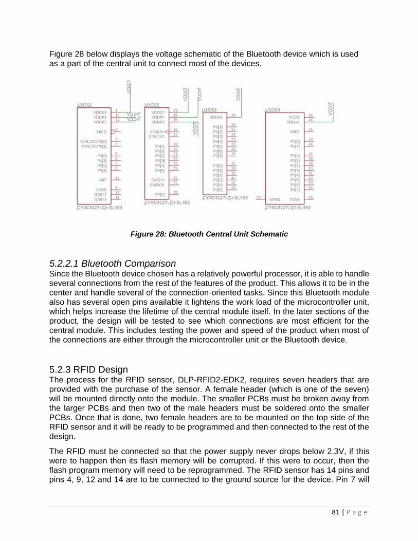
81 | P a g e
Figure 28 below displays the voltage schematic of the Bluetooth device which is used as a part of the central unit to connect most of the devices.
Figure 28: Bluetooth Central Unit Schematic
5.2.2.1 Bluetooth Comparison Since the Bluetooth device chosen has a relatively powerful processor, it is able to handle several connections from the rest of the features of the product. This allows it to be in the center and handle several of the connection-oriented tasks. Since this Bluetooth module also has several open pins available it lightens the work load of the microcontroller unit, which helps increase the lifetime of the central module itself. In the later sections of the product, the design will be tested to see which connections are most efficient for the central module. This includes testing the power and speed of the product when most of the connections are either through the microcontroller unit or the Bluetooth device.
5.2.3 RFID Design The process for the RFID sensor, DLP-RFID2-EDK2, requires seven headers that are provided with the purchase of the sensor. A female header (which is one of the seven) will be mounted directly onto the module. The smaller PCBs must be broken away from the larger PCBs and then two of the male headers must be soldered onto the smaller PCBs. Once that is done, two female headers are to be mounted on the top side of the RFID sensor and it will be ready to be programmed and then connected to the rest of the design.
The RFID must be connected so that the power supply never drops below 2.3V, if this were to happen then its flash memory will be corrupted. If this were to occur, then the flash program memory will need to be reprogrammed. The RFID sensor has 14 pins and pins 4, 9, 12 and 14 are to be connected to the ground source for the device. Pin 7 will

82 | P a g e
be where the power supply will be connected to and the aim is for it to be between 3V and 5V. Pin 1 will be connected to the host device, in this scenario the device can be either the MCU or the Bluetooth module and this pin will act as the input. Pin 2 will also be connected to the host device, this will be the output pin for the console.
5.2.3.1 RFID Choice The RFID sensor we decided to implement for this project is the is our first option, the DLP-RFID2. There are multiple reasons think it is the best choice and the first is the security factor. The DLP-RFID2 operates at 13.56 MHz classifying it as an HFRFID sensor. HFRID sensor are typically used for monetary transactions were as the other two options were LFRFID sensors and are primarily used for tracking. Real-time security was specifically mentioned as an application for the DLP-RFID2 was as there was no mention of the other two datasheets.
The second reason is the price point. The DLP-RFID2 cost nearly a third of the other two option being priced at $34.95 while the RWD-QT-R2-ND is priced at $121 and the RI-STU-MRD2 is priced at$94.50. The final reason we chose the DLP-RFID2 is that it is more versatile than our other two options. It is versatile in the way that it is the only one of the three to come equipped with an internal antenna and be able to have an external antenna added on to it. It also was better in the communication department because it has multiple modes of interface. Table 26 contains its technical specifications.
Table 26: RFID Specs
Dimensions Reader/ Writer Speed
Operating Voltage
Operating Current
TTL Serial Interface
Pins
41.91 x 18.67 x 4.32 mm
13.56 MHz 3.0V-5.0V 55 mA 115,200 Baud
14
5.2.3.1a Schematic The schematic for the RFID device is dependent on a connection to the Bluetooth
module of our central console. The first and second pins are directly connected to the
pins of the same name in the Bluetooth module and the VCC is also connected to the
VCC of the same device. The connection to the Bluetooth device needs to be
maintained so that the code for each RFID that is connected to the sensor remains
saved in the storage unit of the module. The operating voltage must also be maintained
between 3 and 5 V so that the programming of the scanner is not corrupted. If the
programming were to be corrupted then the device will need to be reprogrammed to
operate.

83 | P a g e
Figure 28 below displays the schematic with relation to our central console.
Figure 28: RFID Design Schematic
5.2.4 Fingerprint Sensor Design The fingerprint reader design is fairly simple as it only has 4 wires that require
connection, two of which are to power the system. The fingerprint sensor must be
connected so that it’s voltage never drops below its operating voltage of 3.3V-5V. The
VCC of the device must be connected to the voltage source and the ground must be
connected to the ground. The reason why we need to maintain the voltage levels at a
proficient point is so that there isn’t any data loss or any possibilities of there being an
interruption to the user’s entrance into the establishment of choice. A shortage of power
can either shut off the entire device or send incomplete images of the fingerprint to the
central unit. If this were to occur, then there is a possibility that if a fingerprint is saved
and is corrupted the user may not be able to enter. Resistors may need to be added if
there is any overcurrent that will go through the device.
5.2.4.2 Fingerprint Sensor Choice We decided to use our first option of the Capacitive Fingerprint Reader. This option fit us of the best because it was in line with our goals of being low power and security the best. This component had the lowest operating current out of the three even though all of them had the same minimum operating voltage and it had the lowest maximum. The Capacitive Fingerprint Reader is also the best option in regards to security because having a false

84 | P a g e
acceptance rate of .0001% and false rejection rate of .01% is standard across the board for the sensors because this is a capacitive sensor it cannot be spoofed by using a picture of the fingerprint like the other two options. Table 27 lists the specs of the Fingerprint sensor.
Table 27: Fingerprint Sensor Specs
Module Dimension
Sensor Dimension
Sensing Area
Operating Voltage
Image Pixels
Sensor Life Time
45.0 mm x 30.0 mm
33.4 mm x 20.4 mm
9.6 mm x 12.8 mm
3.3V-5V 192 x 256 3-5 Years
5.2.4.1a Schematic The schematic for the fingerprint design will be connected to the 5V pin from the Beaglebone device as well as the ground. This will be enough power to operate the device. The TXD of the device must be connected to the RXD of the central unit and the RXD must be connected to the TXD of the central unit. The TXD and RXD pins are what will be sending images of the fingerprint back and forth between the sensor and the central unit. This will be how and where the images will be stored for future use. These pins must be properly connected, otherwise the device will not function properly. Figure 29 shows the connections made under the fingerprint sensor (J1) to the central unit. Table 28 shows what each connection on the sensor is labeled as.
Figure 29: Fingerprint Sensor Connections

85 | P a g e
Table 28: Fingerprint Sensor Labels
1 RST
2 WAKE
3 TXD
4 RXD
5 GND
6 VCC
5.2.5 Accelerometer Design The accelerometer will come with several pins that will be needed to set up the device and solder it. Using a breadboard, it is intended to have two sets separated and have one 3 pin set towards the top and an 8 pin set towards the bottom. The long side of the pins will be pointing downward into the breadboard. For the hardwired connection, the Vin sensor must be connected to the 3V DC connection and the two ground pins must be connected to each other. The sensor’s SCL must be connected to either the board SCL or SCK, and all the other pins are simple connections to each other. Pins CS and INT will be connected to free input/output pins since these pins are where the information from the accelerometer will be transferred.
The pinout for the accelerometer labeled VIN1-8 are displayed in Table 29.
Table 29: LIS3DH Pin-Out
Pin Connection
1 Vin
2 3Vo
3 GND
4 SCL
5 SDA
6 SDO
7 CS
8 INT
5.2.5.1a Schematic The figures 30-33 shown below show the different schematic used in order to properly use the LIS3DH accelerometer. A 3.3 voltage regulator was used in order to maintain consistent voltage with very low drop-out. The Figure 32 shows the pullup resistors for the SCL and SDA lines that are used for the I2C clock and data pins respectively. In order to use SPI communication, the CS line, the chip select line, needs to be dropped top low to start an SPI transaction. Figure 33 shows the connectors that will be connected directly to the micro controller and power supply.
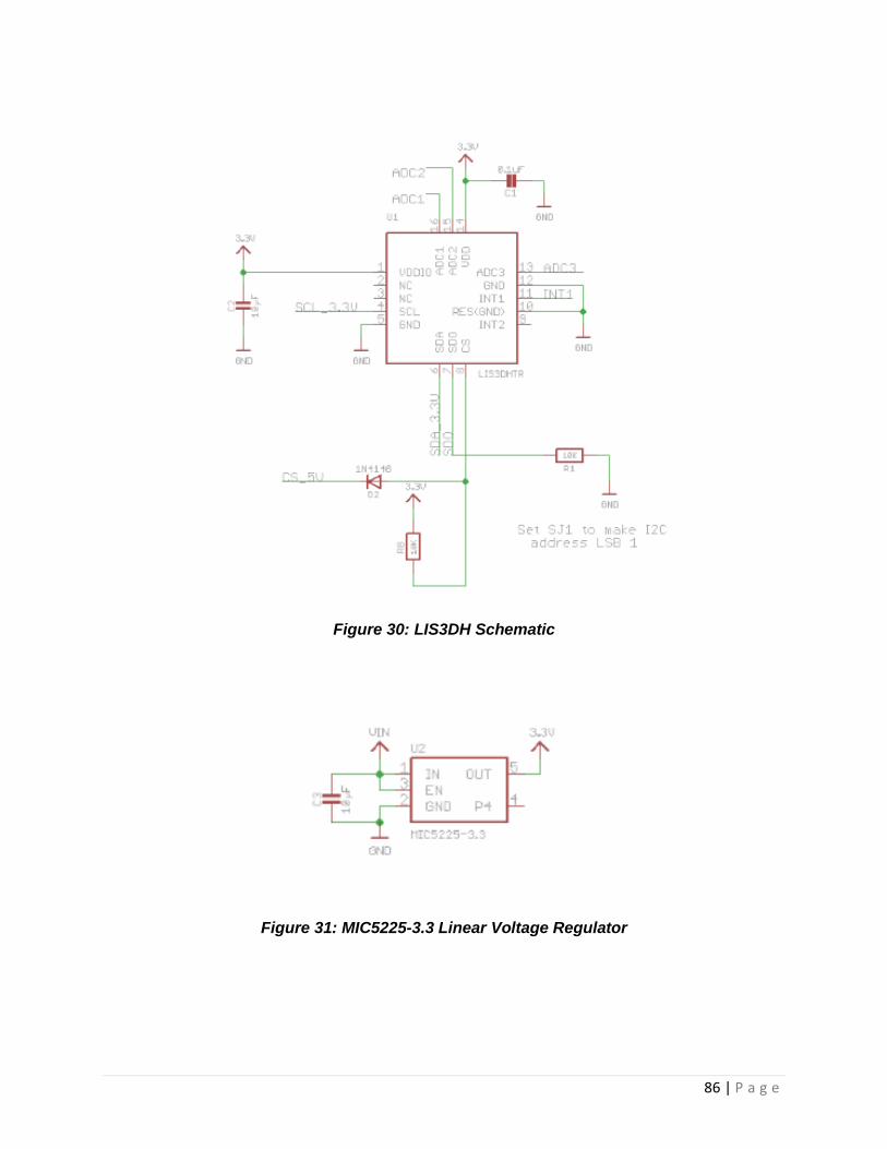
86 | P a g e
Figure 30: LIS3DH Schematic
Figure 31: MIC5225-3.3 Linear Voltage Regulator

87 | P a g e
Figure 32: Accelerometer Pull-up Resistors
Figure 33: LIS3DH Connectors
5.2.6 Microcontroller Design In this section the reasoning behind our microcontroller choice will be discussed as well
as the actual design of the product. The microcontroller is a detrimental part of the
design of our product due to the fact that it handles the bulk of the communication
between the other modules and it is used as the command unit for the entire device.
The microcontroller will also assist with the connection to the wireless applications and
due to its location in the design, it will balance out most of the potential issues that might
occur with the voltage.
Figure 34 shows the circuitry behind the parts that can act as voltage sources for other
parts in the design.
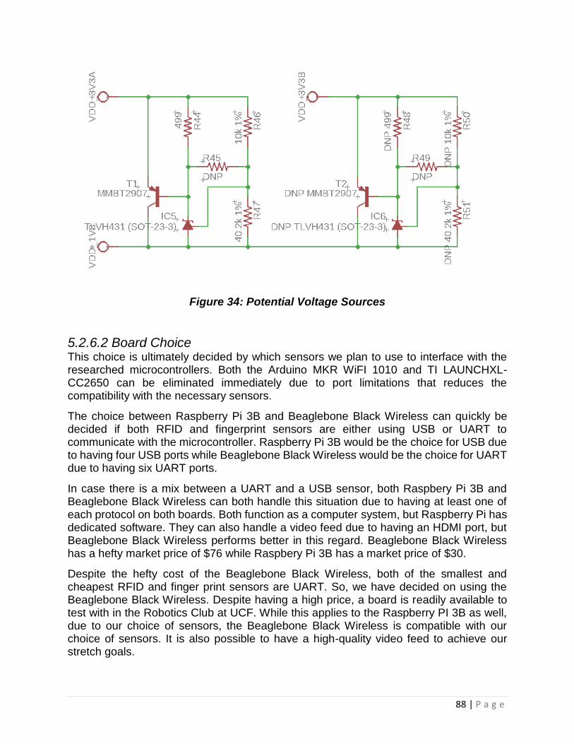
88 | P a g e
Figure 34: Potential Voltage Sources
5.2.6.2 Board Choice This choice is ultimately decided by which sensors we plan to use to interface with the researched microcontrollers. Both the Arduino MKR WiFI 1010 and TI LAUNCHXL-CC2650 can be eliminated immediately due to port limitations that reduces the compatibility with the necessary sensors.
The choice between Raspberry Pi 3B and Beaglebone Black Wireless can quickly be decided if both RFID and fingerprint sensors are either using USB or UART to communicate with the microcontroller. Raspberry Pi 3B would be the choice for USB due to having four USB ports while Beaglebone Black Wireless would be the choice for UART due to having six UART ports.
In case there is a mix between a UART and a USB sensor, both Raspbery Pi 3B and Beaglebone Black Wireless can both handle this situation due to having at least one of each protocol on both boards. Both function as a computer system, but Raspberry Pi has dedicated software. They can also handle a video feed due to having an HDMI port, but Beaglebone Black Wireless performs better in this regard. Beaglebone Black Wireless has a hefty market price of $76 while Raspbery Pi 3B has a market price of $30.
Despite the hefty cost of the Beaglebone Black Wireless, both of the smallest and cheapest RFID and finger print sensors are UART. So, we have decided on using the Beaglebone Black Wireless. Despite having a high price, a board is readily available to test with in the Robotics Club at UCF. While this applies to the Raspberry PI 3B as well, due to our choice of sensors, the Beaglebone Black Wireless is compatible with our choice of sensors. It is also possible to have a high-quality video feed to achieve our stretch goals.

89 | P a g e
5.2.6.1a Schematic The microcontroller is meant to be connected in the center of the device along with the
Bluetooth module. The voltage source will also be connected to this device as it will split
between the Bluetooth and microcontroller devices. Fortunately, the operating voltage
for the Beaglebone device is only 5V and can easily be used from the voltage source.
An adapter will be added to the Beaglebone device in order to make it compatible with
the AA batteries and allowing the device to be more mobile. This does not interfere with
the design and it still allows the Beaglebone to act as a source for up to four separate
devices. The microcontroller will also handle a bulk of the connections traveling
throughout the device. This device has several UART pins which will be used as
connections to some features such as the fingerprint sensor.
Figure 35 displays the schematic of the Beaglebone which is used as a part of the central unit to connect most of the devices.
Figure 35: Beaglebone Schematic
5.2.7 Power Supply Design The power supply that the group is going to use for this project are 4 AA batteries. These batteries are going to be placed into a battery holder and mounted into a fixture on the outside of the door. A polarity protection circuit will be implemented to protect the device if the batteries are incorrectly installed. Also, voltage regulators will be used to convert the batteries voltage to the proper voltages in order to power the microcontroller and the motor.

90 | P a g e
5.2.7.1 Battery Jumper/Polarity Protection Schematic The Figure 36: Polarity Protection Schematic, shown below, is used to supply power throughout the system. The jumper labeled battery holder connects the PMOS to the 4x AA battery holder. This circuit ensures polarity protection so that if the batteries are improperly inserted the PMOS will not turn on resulting in no voltage at the 6V terminal.
Figure 36: Polarity Protection Schematic
5.2.7.2 Voltage Regulator Schematic The figure 37: Voltage Regulator Schematic, shown below, takes the voltage from the batteries and regulates it to its desired voltage. It should be noted that the BATTERY component in the schematic is only a symbol for demonstrational purposes, the input of this regulator will actually be connected to the 6V wire from the output of the PMOS.
Figure 37: Voltage Regulator Schematic

91 | P a g e
5.2.8 Keypad Design Since the keypad device simply acts as a resistor for the circuit, it can be connected in series to the other connections and the source. Once the pin connections are figured out, it’s a straight forward connection to the board. Afterwards, if an LCD screen is necessary it can be connected to the power end of the overall device and programmed to operate with the keypad. This will require a connection to the 5V source (presumably the BLE device connected in the center of the circuit), a ground and two wires in the analog portion of the system. Knowledge of the locations of the pins is a requirement when it comes to programming the keypad to work with any additional features or devices.
In order to set up the keypad for implementation, the in and out pins need to be labeled and tested. This can easily be done by building a simple test circuit using an LED and a current limiting resistor to a 5 V source or the Beaglebone device. The ground wire will need to be connected from one pin of the keypad to the LED (which is connected in series with the resistor, which is also connected in series to the ground of the source.) The next step is to press a button in the first row and to leave it held while connecting the other wire to the other keypad pin. This other wire will be the direct connection from the other keypad pin to the positive end of the source. Depending on which button turns the LED on will determine what each pin is connected to.
5.2.8.1a Schematic The schematic for the keypad is extremely simple due to the fact that it acts as a
resistor for the circuit. The first pin is simply connected to ground and the last pin is
connected to one of the VCC’s of the Bluetooth module. In the example shown below it
is connected to an LED diode as a placeholder. The LED diode was used initially to
check the pins of the keypad itself and is used to verify that the module is operating
properly.
Figure 38 shows the schematic for the connection of the keypad and when the source wire is changed from the first pin to any other pin, this can also be used to function as a pin check for the keypad device.
Figure 38: Keypad Connection Schematic
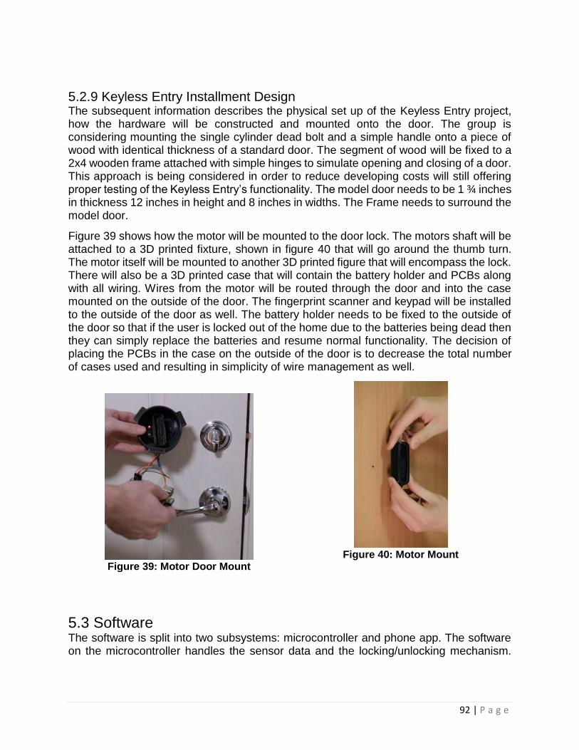
92 | P a g e
5.2.9 Keyless Entry Installment Design The subsequent information describes the physical set up of the Keyless Entry project, how the hardware will be constructed and mounted onto the door. The group is considering mounting the single cylinder dead bolt and a simple handle onto a piece of wood with identical thickness of a standard door. The segment of wood will be fixed to a 2x4 wooden frame attached with simple hinges to simulate opening and closing of a door. This approach is being considered in order to reduce developing costs will still offering proper testing of the Keyless Entry’s functionality. The model door needs to be 1 ¾ inches in thickness 12 inches in height and 8 inches in widths. The Frame needs to surround the model door.
Figure 39 shows how the motor will be mounted to the door lock. The motors shaft will be attached to a 3D printed fixture, shown in figure 40 that will go around the thumb turn. The motor itself will be mounted to another 3D printed figure that will encompass the lock. There will also be a 3D printed case that will contain the battery holder and PCBs along with all wiring. Wires from the motor will be routed through the door and into the case mounted on the outside of the door. The fingerprint scanner and keypad will be installed to the outside of the door as well. The battery holder needs to be fixed to the outside of the door so that if the user is locked out of the home due to the batteries being dead then they can simply replace the batteries and resume normal functionality. The decision of placing the PCBs in the case on the outside of the door is to decrease the total number of cases used and resulting in simplicity of wire management as well.
Figure 39: Motor Door Mount
Figure 40: Motor Mount
5.3 Software The software is split into two subsystems: microcontroller and phone app. The software on the microcontroller handles the sensor data and the locking/unlocking mechanism.

93 | P a g e
The software for the phone app acts as the user interface for the security functions of the smart lock.
5.3.1 Connect/Setup Mode Logic Flow The Beaglebone Black Wireless microcontroller runs on a Debian operating system that can be accessed on the Cloud9 IDE. The board naturally supports Android, allowing for an easier interface with an Android phone app. The microcontroller is responsible for being a hardware interface that can control.
To ensure security of the sensors, checksums can be used for data integrity from errors that can occur during collisions for the cryptographic hash function. The AES, SHA-2, and other ciphers are considered to increase the security of the authentication without sacrificing speed and serves as the primary source of security for all authentication methods.
Using Node.js technically requires the least number of steps to get started. However, with the lacking experience in JavaScript, it may be more intuitive cross-compile Eclipse onto the Beaglebone Black Wireless to code in C++ instead. This step depends on the difficulty of learning JavaScript.
The management of the settings of the smart lock is done on the phone app side. The phone app will have access to the database, whether online or on the microcontroller. The phone and the microcontroller on the smart lock should maintain a connection-based link for Wi-Fi/Bluetooth. This is their primary line of communication and it determines how the smart lock functions. However, once the settings are set, the microcontroller should be able to function independently from the phone app. While settings and logs are to be updated to the database for the phone app to access, the lack of Wi-Fi and Bluetooth should not inhibit the security of the smart lock.
When the smart lock fails to communicate with Wi-Fi or Bluetooth, it will store its logs within the memory embedded within the microcontroller. Once a connection is reestablished with Wi-Fi or Bluetooth, it will automatically attempt to update the logs in the database. A notification will be sent to the phone letting you know that the logs are being updated.
The motors that unlock the door is controlled by the unlocking mechanism that controls the pulse-width modulation that allows the motors to run.
5.3.2 Wi-Fi Communication Setting up Wi-Fi on the Beaglebone Black Wireless is done by opening SSH while connecting to it over USB and enabling it.
To connect the smart lock to Wi-Fi, the phone app will be used as a user interface to do so. The phone will initially scan for the smart lock to connect to it through Wi-Fi or Bluetooth. The phone will then determine what Wi-Fi networks the smart lock can connect to and give the user the option to choose a network. There will be an indicator to show that the device is connected to the Wi-Fi through an LED.

94 | P a g e
In the advent of a Wi-Fi connection failure, the device attempts to connect to the same network for a period of at least 5 minutes. During this time the Wi-Fi LED will flash and when the smart lock cannot connect after the timeout period, the LED will shut off and the smart lock cancels the attempt to connection to Wi-Fi.
While the smart lock is connected to Wi-Fi, it will remain on standby until a phone app connects to it. The Wi-Fi will periodically send status updates across Wi-Fi to the application. The smart lock shall update according to changed settings on the application, e.g. Wi-Fi reconnect period, autolock timeout, RFID settings.
Every event is logged and can be viewed on the phone app. Users can change their settings to be notified when events occur to be informed when something happens to the smart lock over Wi-Fi. As a stretch goal, a video feed can be streamed across Wi-Fi if a camera is connected to the smart lock.
5.3.3 Bluetooth Communication Initializing Bluetooth on the Beaglebone Black Wireless is done by opening SSH while connecting to it over USB and enabling it.
Connect to the smart lock with your phone. Open the phone app and register your phone as a user of the lock. If you are the first user, register another form of authentication to ensure anonymous individuals do not have control over the smart lock. This measure is designed for households that do not connect to the smart lock with a Wi-Fi connection. Smart lock settings can be accessed when the Bluetooth connection is maintained after appropriate authentication has been met.
Bluetooth can be set up to varying levels of security. Bluetooth may serve as an additional layer of verification to unlock the smart lock by having the smart lock recognize that the device connected to it is a user within its database. At the lowest level of security, the smart lock can automatically unlock when it recognizes the Bluetooth user for convenience. Every event will be logged, and the app can be set up to notify you of all the events that have transpired when the phone is connected over Bluetooth.
5.3.4 Fingerprint Sensor The software on the controller will serve as a hardware interface for the fingerprint sensor and the phone app. The software on the phone app will use the functions of the hardware interface to access the fingerprint sensor and the database for the user IDs. This allows the phone app to act as a user interface.
The fingerprint sensor will use an enrolling scheme initiated by the phone app. This is done by selecting the fingerprint option on the user settings for an ID. The phone application will ask the user to place the finger on the fingerprint sensor when initiated to scan the fingerprint. Once the fingerprint is scanned, the user ID will be received from the database to enroll the fingerprint with the specific ID.
The phone application will then ask the user to verify the fingerprint by placing the same finger on the fingerprint scanner to scan the finger again. This test is important to ensure
95 | P a g e
the fingerprint that was scanned can reliably reference the user ID it should be associated to. From here on it will log the failure/success of scanning a fingerprint into the database of the smart lock. When the fingerprint verification succeeds, this new fingerprint will become one of the methods of user authentication for opening the smart lock.
Most of the coding for the fingerprint sensor will be done in the hardware interface section under the sensor logic category. The microcontroller must have methods to communicate with the fingerprint sensor through serial UART. While the software can be built to communicate through USB, the ports are limited on the Beaglebone Black Wireless microcontroller for USB.
This code should have various methods that allow the fingerprint sensor to function properly. A method that enrolls a fingerprint to an ID is necessary to make the connection between user and fingerprint. Another method that checks fingerprints to see if it is within the database is necessary for a similar reason. This fingerprint check should have a low time complexity to minimize the impact that multiple users have on performance. The code for the fingerprint sensor must perform optimally for at least 20 users.
5.3.5 RFID Sensor The software on the controller serves as a hardware interface for the RFID sensor and the phone app. The software on the phone app will use the functions of the hardware interface to access the RFID sensor and the database for the user IDs. This allows the phone app to act as a user interface. The RFID sensor will use an enrolling scheme initiated by the phone app.
This process is nearly identical with the fingerprint sensor. The difference being that it may detect multiple RFIDs so an added layer of isolation is necessary. The phone will tell the user if multiple RFIDs are detected during the enrollment process. This part of the enrollment process should also check if any of the RFIDs are already enrolled and remove them from the less of possible RFIDs. Updating an RFID that is already associated with a user ID will be part of another procedure that requires further authentication.
The RFID sensor is also used for the automatic unlocking code that is set by the phone app. This setting can be set to unlock the door upon sensing the RFID sensor within range of the smart lock. A high-level log will be sent to all users that the associated user unlocked the door for security reasons. This high-level will send a notification to the phone app by default when the door unlocked this way. This notification can be manually disabled by the user, but it will remain in the log.
This auto-unlock method can also tie along with other methods of authentication to strengthen the security. One example is with Bluetooth/WiFi to send a notification to the phone of the user to unlock the door with a tap of the notification.
This code should have various methods to allow the RFID sensor to function and stay secure. The enrollment and checking are necessary for an RFID to make a connection between the user and the RFID. This check should also have a low time complexity to minimize the impact that multiple users have on performance. The check should also find
96 | P a g e
a flag in the database that shows if the auto-unlocking feature is enabled for any user of RFIDs that are detected.
5.3.6 Keypad Connection The software on the controller serves as a hardware interface for the keypad and the phone app. With the keypad’s ability to send character data, passwords can be achieved by the keypad connection. As such, this is subjected to password strength standards. This varies from a PIN to an alphanumeric password. For implementation, any alphanumeric keypads to be considered would need a display to use easily. This is due to how the software for setting a password will function.
Setting up a password begins with a password entered in the phone app. The phone app will then tell the user to enter the same password on the keypad. Once the password is entered, the phone app will compare the password entered on the phone and the password entered on the keypad for verification. Once the password is verified, the password will be saved into the database as another form of authentication for the user.
Advanced alphanumeric keypads considered will be required to press the key multiple times to get a letter. The user should be able to see what alphanumeric character they chose. As such a display, such as an LCD, is necessary to allow an advanced alphanumeric password to be entered. Attaching an LCD adds a layer of complexity to the smart lock. If a display is not added, then a PIN is the most reasonable form of password since each button corresponds to a single number.
Using a PIN is associated with the ISO 9564 standard which mandates PIN encryption. Since PIN encryption must be secure independent of secrecy, it is likely a cipher will need to be relied on to encrypt the PIN and store the encrypted pin in the database.
5.3.7 Android / iPhone Application The Android/iPhone application is a mandatory user interface to use the smart features of the smart lock. This is because the Android/iPhone application is the primary interface to handle security settings. This application is what allows the smart lock to connect to the internet through Wi-Fi. This application can be used to interface to the smart lock with Bluetooth as well. Doing so will require a form of authentication to be set up.
Users will be stored in the database of the smart lock and each user will be able to receive notifications on events that occur with the smart lock. Most events are logged by default, but significant events will also send a notification to all users. Various settings can be changed by the root user. The root user can be created by the first individual who used the phone application to connect to the device and create a form of authentication. Requiring a mode of authentication to become a user eliminates the threat of an anonymous user from becoming the root user due to the need to physically interact with the device.
The phone application controls many features. A timer is set to automatically lock the door if it is open for a period of time. This time can be changed with the phone application to

97 | P a g e
avoid the case of needing to reopen the door when it is expected to be used quite frequently. It may also increase the level of authentication necessary to open the smart lock. The smart lock could also notify users if someone is knocking on the door. A knocking combination could also be recognized used as a layer of authentication. Depending on the strength of the RFID sensor, it is possible that the appropriate Bluetooth and RFID signal will allow the application to automatically unlock the door upon approaching.
6 Prototype Construction and Coding This section covers the steps taken to build a successful prototype of the smart lock. The parts that are acquired will be discussed as well as the equipment and facilities used to build the smart lock. The design for each prototype will be discussed in detail for this section. The following sections will be focusing on three different aspects of the prototype. There will be a focus on the parts acquired, the hardware prototype, and the software prototype. The parts acquired section will focus on where and what parts were acquired, as well as where these parts can be found. The hardware prototype will focus on both the circuitry of the design and the packaging for the overall smart lock device. The software prototype section, which is also named the User Interface Prototype will focus on the function of the app and the programming required to solidify the connections within the product. There will also be attention on the error identification and problem solving aspect of the prototype.
6.1 Parts Acquisition The parts required for purchasing will be the fingerprint and RFID sensors, PIN keypad, accelerometer, Bluetooth chip, and a PCB board. A motor as well as a power supply container, voltage regulator, and a power protection device. The majority of the components purchased for this project were obtained from Digi-Key with the exception the Fingerprint sensor obtained from Waveshare. The Beaglebone Black board was obtained from the UCF Robotics Lab, but it can also be obtained via Mouser or Adafruit. The motors can be obtained from Amazon. This project was completely self-funded. It revolved around a budget of about $200.00 and we split the entire costs of the project four ways.
6.1.1 Funding This entire project was self-funded as it was a non-sponsored idea and is a concept pushed by our own curiosity and enjoyment of the subject. The total cost of the project will be split 4 ways between each of the members of the group. Due to the fact that this project is self-funded, it gave us a focus on making the product economically efficient. We focused on a low-budget design and it assisted with pushing the design to be cheaper than the other products that are sold by competitive retailers. The issue this brought was the fact that some parts were either not powerful enough or they consumed too much power. Although many parts were faulty and did not fall into the category of

98 | P a g e
pieces that were needed, after enough research the perfect parts were found for the use of this product.
6.2 Equipment and Facilities The Robotics Club is the most significant facility which offers major parts and tools for creating the smart lock. A variety of microcontrollers including the Beaglebone Black Wireless that the team chose for the main controller for the project is readily available to use for the smart lock. A 3D printer is available at The Robotics Club. This can be used when there is a need to create an enclosure for the smart lock. A soldering station with multiple breakout boards, wires, and wire connectors including Molex is also available to help build the electrical design of the smart lock. Plenty of resistors, capacitors, inductors are available to adjust the design. The Robotics Club also offers extra devices such as network cards, LEDs, and LCD screens which gives more options to change the design of the smart lock. DC power supplies, oscilloscopes, and multimeters in the lab can be used to test the electrical integrity. AC to DC adapters, ethernet cables, USB cables, serial cables are available in excess.
The Innovation Lab has a lot of similar equipment with the Robotics Club at UCF that can also be used for the project:
• Soldering stations
• Resistors
• Capacitors
• Inductors
• Function generators
• DC power supplies
• Oscilloscopes
• 3D printers The main difference is that The Innovation Lab has superior 3D printers. This can largely be discarded if using a used smart lock as the enclosure for our smart lock.
6.3 Hardware Prototype In this section we will discuss the implementation of the circuit design to test the functionality and efficiency of our product. There will be a section dedicated to the printed circuit board that we are using and details regarding it. This will also be the host to the circuit connections of our product. The other section will be the casing prototype which will be the physical set-up of our product and how all of the features are set up. This following sections will describe everything in further detail and address potential problems and potential solutions that will be implemented for the final product prior to presentation.

99 | P a g e
6.3.1 Printed Circuit Board The printed circuit board is a detrimental part of the system that is being constructed. This is what is going to hold the internal circuitry of the product and it allows additional parts that might be necessary to be easily soldered in by surface mount technology. If surface mount technology is something that becomes unobtainable, we can simply manually connect everything using a soldering iron. The printed circuit board will be set up through a computer based program and it will be created through a step-by-step process. We will be using EAGLE as our program to create the PCB layout for our project’s design.
Prior to implementing the design onto a PCB board all of the components and wire set-ups need to be checked on a simulation. Afterwards the next step will be to move this onto a breadboard to measure all of the current and voltage levels to make sure that everything is being transferred accurately. This is a very important step to take, because if the current is too high in any part, then it will compromise the rest of the design. This can cause some parts to overheat and require the parts to be reordered to and it will be very damaging to the budget. The voltage also needs to be observed to make sure the correct amount of voltage is being distributed to the different parts. If the voltage falls below the operating voltage this could damage the programming or the memory of certain devices that are implemented in the design.
Creating the layout for the PCB on the EAGLE program is simply transferring a 2-dimensional layout to a 3-dimensional one. Afterwards all it takes is to neatly organize the cables in the layout to have a plausible design that should reach 100% or as close to it as possible when a check-up is started. The number of layers that needs to be used is also to be noted and recorded. The most common layer count for simple designs is two, and due to the fact that this circuit might get complex due to the inclusion of the motor it can be four layers. These plane layers are thin copper sheets that may be applied to the PCB board when it is ordered. This layout can then be used as a guideline for the PCB set-up and after the trace patterns are corrected, the physical connections can be initiated. The green coating on the PCB board is called soldermask and its one of the different types of coatings that can be used. We will be using the recommended PCB thickness, which is 0.062 inches. This is due to our inexperience with these printed circuit boards.
When the tracing is being made for the PCB board, it must be noted that the width and
spacing between the holes in the board are extremely important. There needs to be
proper spacing between the holes for the connections to be established correctly. It is
recommended to use a snap grid, because this will allow a neat and well organize
layout for the parts that will be connected on the PCB. The snap grid helps “snap” all of
the different parts into permanent positions. Another design factor that is recommended
to have in this layout is the conductor capacitance, it is used to establish how much
electrical energy is stored for a stated potential. Characteristic impedance is also used
to establish the ratio between the voltage and current that is crossing through the board
that is being created. There are several equations that come with these PCB additions
that can be used to establish required parameters that may need to be included within
the PCB design to have a properly functioning device.
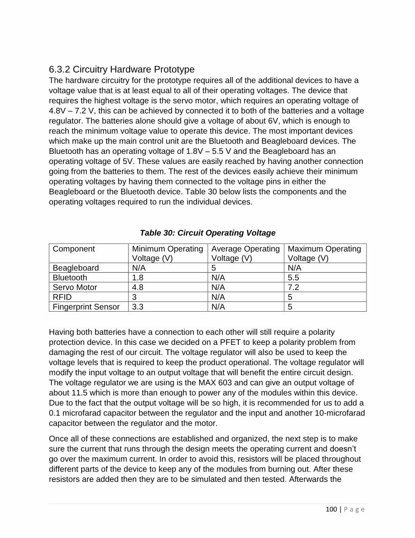
100 | P a g e
6.3.2 Circuitry Hardware Prototype The hardware circuitry for the prototype requires all of the additional devices to have a
voltage value that is at least equal to all of their operating voltages. The device that
requires the highest voltage is the servo motor, which requires an operating voltage of
4.8V – 7.2 V, this can be achieved by connected it to both of the batteries and a voltage
regulator. The batteries alone should give a voltage of about 6V, which is enough to
reach the minimum voltage value to operate this device. The most important devices
which make up the main control unit are the Bluetooth and Beagleboard devices. The
Bluetooth has an operating voltage of 1.8V – 5.5 V and the Beagleboard has an
operating voltage of 5V. These values are easily reached by having another connection
going from the batteries to them. The rest of the devices easily achieve their minimum
operating voltages by having them connected to the voltage pins in either the
Beagleboard or the Bluetooth device. Table 30 below lists the components and the
operating voltages required to run the individual devices.
Table 30: Circuit Operating Voltage
Component Minimum Operating Voltage (V)
Average Operating Voltage (V)
Maximum Operating Voltage (V)
Beagleboard N/A 5 N/A
Bluetooth 1.8 N/A 5.5
Servo Motor 4.8 N/A 7.2
RFID 3 N/A 5
Fingerprint Sensor 3.3 N/A 5
Having both batteries have a connection to each other will still require a polarity
protection device. In this case we decided on a PFET to keep a polarity problem from
damaging the rest of our circuit. The voltage regulator will also be used to keep the
voltage levels that is required to keep the product operational. The voltage regulator will
modify the input voltage to an output voltage that will benefit the entire circuit design.
The voltage regulator we are using is the MAX 603 and can give an output voltage of
about 11.5 which is more than enough to power any of the modules within this device.
Due to the fact that the output voltage will be so high, it is recommended for us to add a
0.1 microfarad capacitor between the regulator and the input and another 10-microfarad
capacitor between the regulator and the motor.
Once all of these connections are established and organized, the next step is to make
sure the current that runs through the design meets the operating current and doesn’t
go over the maximum current. In order to avoid this, resistors will be placed throughout
different parts of the device to keep any of the modules from burning out. After these
resistors are added then they are to be simulated and then tested. Afterwards the

101 | P a g e
design will be ready to be loaded onto the PCB and be prepared to be placed onto a
prototype of the physical casing.
6.3.3 Smart Lock Casing Prototype The casing for the overall design will be large enough to fit the entire printed circuit
board as well as containing the access modules on the exterior of the casing. The
access modules that will be located on the outside will be the sensors for the RFID and
fingerprint, and the keypad. The size of the smart lock itself is intended to be the width
of the door, within this there will be the PCB which is what should not be exposed to the
outside. This is to avoid any damage to the hard wiring of the system from direct
exposure to extreme temperatures, humidity, or wear-and-tear.
The purpose for protecting the printed circuit board is due to the fact that extreme
temperatures can easily affect the current and voltage levels that are generated within
the circuit system. These reasonings were listed in the ethical constraints section of this
report, where it can be noted that the exposure can put the safety of the user of the
product at risk. The batteries to power the system will also be located within the casing
to protect the batteries as they are sensitive to the factors that they would be exposed to
while being in the exterior. There is full intention of having an outline in the back of the
casing that can be screwed in and out in order to have reliable access for the user to
change the batteries. This will be accessible from the inside of the establishment that
this lock will be installed in. Table 30 below lists the components and the dimensions for
the modules located on or near the exterior of the product.
Table 30: Module Dimensions
Components Dimensions (mm) [length x width]
Fingerprint Sensor 33.40 x 20.40
RFID 41.91 x 18.67
Keypad 177.8 x 129.54
Servo Motor 40.00 x 19.00
The dimensions from the Table 30 can be used to provide a rough estimate required for
the size of the casing, which would need to be about 300 mm by 200 mm to contain all
of the features that are shown to be located on the outside. The casing will most likely
need to be larger by another 100 mm per dimension in order to have a manual lock as a
failsafe. The focus for the dimensions is based on the sizes of the exterior features due
to the fact that this is where most of the features will be located. Further details for the
casing will be modified as the design for the rest of the device is updated after the
testing phases.

102 | P a g e
6.4 Coding In this section, the methods used to design the software will be discussed. Functionality
of all software features will be explained in detail. The general procedure for each feature
must fulfill will be outlined and will serve as a means of testing the software. The coding
is to be discussed in the two main subsystems: user and hardware interface. The former
being encapsulated within the phone app while the latter is loaded into the microcontroller.
6.4.1 User Interface Prototype The user interface will be contained within the phone app using Android Studio. The
phone app will be required to have permission to use Bluetooth and Wi-Fi on the device
to install this app. The first thing that the app will desire is to scan for the smart lock by
using either Bluetooth or Wi-Fi. Once the phone app has discovered and successfully
connected to the smart lock, it will check for users in the database of the smart lock. If
there are no users registered to the smart lock, it will initiate the first-user setup.
The first-user setup will ask for a unique username to assign a unique user ID for the
user. This user ID will be invisible to the user and stored in the database. A first and last
name can also be associated with the user for personal identification. The first form of
authentication which will be attempted by the phone app is using the MAC address of the
phone as authentication. If the MAC address is successfully obtained from the phone,
the user will also be required to use a password to secure the MAC address form of
authentication.
Despite the MAC address being a form of authentication, due to the reliance of a
password, another form of authentication will be required to recover the password more
reliably for the first user. This is necessary due to the administrative privilege of the first
user. Administrators are the only users capable of granting administrative status to other
users. Every time users are promoted to administrators; the event is logged for all users
to view.
The other forms of authentication available are through fingerprint, RFID, keypad, and
knock pattern. At least one of these forms of authentication are necessary for an
administrator to at least require physical contact with the door for security and reliability
purposes. This limits the danger of virtual attacks while also utilizing the functions of the
smart lock. If any of the smart lock’s physical authentication methods are inoperable, then
it simply means the smart lock is defective and needs to be replaced. However, multiple
physical forms of authentication are recommended for administrators for redundancy so
that if one form of physical authentication proves inoperable, other forms can still be relied
on.
Registering the physical authentication methods follow similar procedures. Upon
selecting a physical authentication method, an enrollment function will be triggered in the
sensor logic of the smart lock. Sensor input will then be requested by the phone app to

103 | P a g e
collect input data from the smart lock. A system to start and stop the input data stream
will be implemented for each type of physical authentication.
The fingerprint enrollment takes the fingerprint that is inputted once it is fully recognized.
The RFID enrollment will allow the user to choose from a list of RFIDs that are recognized
in the vicinity, but it is recommended to have only one RFID visible to prevent confusion.
The keypad enrollment will either use a special key on the keypad to finish the password
or use the phone app. The knock pattern will use the phone app to determine when the
knocking input is complete.
After the input data is submitted to the phone app, the phone app will then request to
repeat the sensor input to verify its integrity. The keypad enrollment is an exception where
instead of the input only being entered again on the keypad, it is also requested to enter
the same input on the phone app. This is done to verify that both the phone and the
keypad are receiving the expected input, which can be useful for debugging serial
communication issues.
Events will be logged as liberally as possible. It may not be possible to log every single
event due to privacy. However, it is important to ensure that adjustments made to the
smart lock can be tracked and made visible to users so that malicious intent does not go
unnoticed. The creation of new users and administrators are logged to ensure that only
intended users gain access to the lock. Every time information on the smart lock database
and a phone is contradictory, the phone’s data is synchronized to the database’s data
and logged. The affected user can see what was specifically changed. Every time the
door is unlocked the event is logged. Knocking on the door will be logged and notify users
based on their settings.
The unlocking mechanism is based solely on the combination of authentication methods
used on the smart lock. These settings can be changed by the respective user. By default,
only one authentication to be necessary to unlock the door. However, for the knock
pattern authentication, it should not be possible for an anonymous individual to unlock the
door simply by knocking on it. Thus, some authentication methods require additional
identity verification to safely unlock the door. The knocking pattern is the most vulnerable
method due to the natural response of a visitor to knock on the door. This method will
require at least two authentication methods to unlock the door. The number of required
authentication methods for other types can be directly adjusted by the user. These
adjustments will be logged for any user to view. The autolocking method can also be
adjusted by the user. This includes the timeout period for autolocking and the method to
temporarily disable the timeout.
6.4.2 Hardware Interface Prototype
The hardware interface is made using an Eclipse to cross-compile C++ code onto the Beaglebone Black Wireless. To start, a cross-compilation toolchain is devised for the ARM processor on the Beaglebone Black Wireless. Then Eclipse for C/C++ developers

104 | P a g e
is installed for Linux to develop the code. A cross compiler prefix is added to a C++ project. This will allow third-party libraries to be cross-compiled into the ARM platform.
Interfaces must be made for each sensor to organize and debug their functionality. Separate classes will be made to represent each sensor. These sensor classes must all contain a function to enroll users with sensor input. Serial libraries will be used, but an encryption class will exist to allow the plaintext data of sensor inputs to be encrypted into ciphertext when entering the smart lock database. The smart lock database will be stored using the phone app while a temporary storage of logs is kept sending to the database when Wi-Fi communication is down.
The sensor interfaces will first be attempted with examples that can be found for them based on their hardware. Otherwise, the team will design a connection to ensure the sensors work properly. Once all the sensors function as intended, a plaintext will be extracted from the sensor data. This will be the main test showing that the sensor interfaces passed. Once the plaintext is extracted from every sensor successfully, the encryption class shall be developed. The encryption follows the Advanced Encryption Standard (AES) for speed and security. Fulfilling the requirements of this standard is the objective of testing the AES class. If the AES is functioning properly, a ciphertext should result from the functions of the class. The AES function should also be able to decrypt the ciphertext back into the plaintext that represents the sensor input.
7 Product Testing This section is where we provide the testing plan for each feature of our Smart-Lock as well as the voltage and power settings. The criteria to label each of the tests for the feature is relatively the same so that we have a standard to work from for each features of this Smart-Lock. The voltage and power setting test features however have different testing pass or fail characteristics because each component is different and may require different voltage and current requirements. This section also covers safety measures that will be followed when testing and constructing the project.
7.1 Safety The following sub sections describes the different safety measures and precautions that need to be taken when assembling and testing the Keyless Entry project. The team addressed all potential hazards that go along with the project, and if any other potential hazards arise in the future they will be added to this section. The following are guidelines that are set in place to avoid any possible injuries.
Safety is the most important part of any project that is developed because everyone wants to go home with no injuries. With this fact as our guiding principle, will follow everyone the rules outlined in the Senior Design Lab. If construction of our Smart-Lock is done outside of the Senior Design Lab it will be done in a similar environment such as the UCF Robotics Club Lab or the Texas Instruments Lab as to maintain the same standards. All soldering will be done with the proper safety equipment worn in a well-lit area for the safety of our

105 | P a g e
team members. When the testing of our circuit begins, we will keep a minimum distance of three feet from the circuit just in case there is too much current that goes into one of our components.
7.1.1 Soldering Iron The below information describes the steps and consideration that needs to be made to properly and safely operate a soldering iron.
• Always wear safety glasses when operating
• Never touch the heating element or the soldering tip, they can reach temperatures up to 400°C
• Hold wires with tweezers or a clamp, heat dissipates through the wire and will cause it to be hot and possibly burn
• Use a wet sponge to keep the soldering tip clean
• Always return soldering iron to stand when not in use, ensure that iron rests flush
• If iron is not being use for an extended period turn off iron
• Solder in a well-ventilated area, if using leaded solder use a venting fan so operator is not exposed to harmful gas
• Keep solvents in proper dispensing bottles to prevent spills and reduce inhalation hazards
• Wash hands thoroughly after soldering
• If eyes exposed to solvents rinse immediately
7.1.2 Power Tools The information listed below details the precautions and steps that need to be taken in order to safely and properly operate power tools to ensure safety.
• If corded power tool ensures that there are no frays, shorts, or exposure in the wire
• Do not touch any moving mechanical parts when operating
• Do not operate with loose clothing, hair, jewelry, or anything that could get caught in moving mechanical objects for it could catch and result in serious injury
• Always wear safety glasses when operating
• Turn off tools when they are not in use
• Practice proper handling of power tools
• Properly store when not being used
• Keep all personal not operating or assisting operation ar a safe distance away from power tools
• Secure work surface, structure, or component properly secured in order to allow for both hands to operate power tools
• Keep tools properly maintains, keep cutting surfaces sharp for best performance
• Follow user’s manual a

106 | P a g e
7.1.3 Electrical Components The subsequent information concisely explains proper safety measures that need to be taken when dealing with electrical components.
• Always wear safety glasses
• Keep the work area dry and decluttered
• Before working with components discharge oneself of static electricity, electrostatic discharge can damage components
• Always ground oneself when handling the components, wrist strap can be used but needs to be tested to ensure proper grounding
• If the device being worked on is powered ensure that it is turned off when assembling and disassembling
• Avoid short circuits, test all leads and make sure ground leads run to the same node
• Do not touch two pieces of equipment at the same time
• Never operate when hands are wet, this could result in damaging components
• When testing the system under power do not touch components with bare skin, use proper equipment with rubber handles to ensure no current passes to operator
• Make sure the system if fully discharged after powering down, capacitors hold voltage after disconnecting from power
7.1.4 Bluetooth Radiation The following information details the risks involved when using Bluetooth devices. Bluetooth devices send signal through radiofrequency energy thus emitting radiation. The amount of radiation emitted varies depending on the class the transmitter belongs to. There are three classes of Bluetooth transmitters. Radiation emission is highest with a class 1 transmitter and lowest with a class 3 transmitter. Table 31 shows the operating range and power of each class of Bluetooth.
Table 31: Bluetooth Transmitter Classification
Class Maximum Power Operating Range
Class 1 100 mW (20 dBm)
100 meters
Class 2 2.5 mW (4 dBm) 10 meters
Class 3 1mW (0 dBm) 1 meter
The most common Bluetooth transmitter is the class 2 transmitter. To mitigate radiation exposure the team will consider using class 2 or class 3 transmitters since they emit lower radiation levels. Also, the distances of the class 2 and class 3 transmitters will be enough for the group's needs.

107 | P a g e
7.2 Testing Environment Our circuit will be tested in a controlled environment so that we know every aspect that is interacting with our circuit. The location of our test will be either in the UCF Robotics Lab or the Senior Design Lab. These areas are also optimal for adjustment to the Smart-Lock in case there are errors in our design that can be fixed. The Smart Lock will be tested outside of its circuit housing so that it will be easier to troubleshoot. These parameters create the ideal testing environment for our Smart-Lock.
7.2.1 Testing Procedure The testing will be done as a group to minimize the chance for errors and ensure that the responsibilities of testing are divided evenly amongst our group members. The testing of Form of Entry and our application well be split up evenly amongst our team. There will also be a checker assigned to each of the test to ensure that the tests are conducted properly, and the results are valid. The alternative would be worse because an error could slip through and we would have a difficult time troubleshooting to find the error. Below in Table 32 and Table 33 is the list of testers and checker for our Forms of Entry, while beneath that is the list of testers and checkers for our application.
Table 32: Authentication Testing Delegation
Forms of Entry Tester Checker
Fingerprint Sensor J. Couch K. Rhu
RFID Sensor K. Rhu J. Couch
Keypad E. Ahrens D. Vo
Table 33: Application Testing Delegation
Application Feature Tester Checker
Remote Locking and Unlocking
J. Couch D.Vo
Lock Access Removal K. Rhu E. Ahrens
Timed Keycode Entry D. Vo J. Couch
Auto-Locking E. Ahrens K. Rhu
Auto-Unlocking K. Rhu E. Ahrens
Entry Notification J. Couch K. Rhu
Break-In Notification D. Vo E. Ahrens
Although we have listed out the individual testing and checking partners, we will all be participating in the final testing. While we are responsible for test the components and features that we designed, we will be testing various portions of our Smart-Lock in quick succession so we will all have to be vigilant if an error occurs. Testing all of the application features and forms of entry in this manner allows us to verify that our Smart-Lock can function in almost any situation. In the following sections, we proceed to out the steps by

108 | P a g e
which each of the application features and forms of entry are tested. We also outline how we test the individual components with our PCB Board to ensure that they function.
7.2.2 Data Logging The tables below outline the criteria for a pass or fail for the final product of our design. The first table shown in Table 34 is for the Forms of Entry for our Smart-Lock. The second table shown in Table 35 is for the testing for the features of our application for Smart-Lock.
Table 34: Authentication Test Procedures
Test Pass Fail
RFID Sensor The Motor rotates in the direction necessary to Unlock the door and the green LED flashes
The Motor does not rotate and the green LED does not flash
Fingerprint Sensor The Motor rotates in the direction necessary to Unlock the door and the green LED flashes
The Motor does not rotate and the green LED does not flash
Keypad The Motor rotates in the direction necessary to Unlock the door and the green LED flashes
The Motor does not rotate and the green LED does not flash
Table 35: Application Test Procedures
Test Pass Fail
Remote-Locking The Motor rotates in the direction necessary to Lock the door and the red LED flashes
The Motor does not rotate and the red LED does not flash
Remote-Unlocking The Motor rotates in the direction necessary to Unlock the door and the green LED flashes
The Motor does not rotate and the green LED does not flash
Entry Record There will be a line of text in the application that states the user that made our Smart-Lock ‘unlock’ in the Entry records section of our application
There will be no text in the entry records section of our application
Lock Access Removal The form of entry used by the tester will cause the
The form of entry used by the tester will cause the

109 | P a g e
red LED to flash and the motor will not rotate
green LED to flash and the motor will rotate
Timed Keycode Entry The Keycode generated by the application will make the motor rotate, the green LED will flash, and once the time limit expires the code will cause neither of those action
The Keycode generated by the application will not make the motor rotate, the red LED will flash or once the limit expires the code will still be able to cause the actions for unlocking
Auto-Locking Once the timer that we set through our application expires the red LED will flash and the motor will rotate in the direction to lock the door
The motor will not rotate in the locking direction and the red LED does not flash.
Auto-Unlocking Once the tester is in within the range that we set through the application the motor will turn in the unlocking direction and the green LED will flash
Once the tester is in range the circuit will have no reaction.
Entry Notification A notification will appear on the smartphone after the tester activates the circuit and triggers the unlock
There will not be a notification on the smartphone
Break-In Notification A notification will appear on the smartphone after the tester shakes the surface the circuit is being tested on
There will not be a notification on the smartphone
7.3 Power Transformation Testing Undervoltage and overvoltage tests are required to satisfy the ANSI standard for
Electrified Locking Devices. Over-current protection is also expected, and ground
continuity tests should be made before the circuit is powered. After appropriate fuses are
attached to the circuit to protect the devices, a ground continuity test is to be performed.
To perform the ground continuity test, the procedure is to test the resistance of the ground
wire. However, a more comprehensive test would also test the line as well as the ground
wire. To do so, the line and ground are connected temporarily and then the GCM is
connected to determine the entire resistance of the protective conductor and the line
resistance. The ground continuity pass succeeds if there is a sufficiently low resistance
to maintain a continuous connection. This version of the test grants a resistance value,

110 | P a g e
but a simpler version of the test is to use a multimeter’s continuity test mode function to
check for continuity. This can be done before a resistance check to quickly determine if
ground continuity passes for fails. All that needs to check if a beep occurs when forming
the same circuit. If a beep does not occur, the connection is not continuous, and the test
has failed. This means that the connection is an open circuit which means that the ground
line may be broken.
Once the ground continuity test is passed an undervoltage test is done. The circuit being
built is considered a class 2 device. Another name for an undervoltage test is an insulation
resistance test. This test attempts to determine the resistance of insulators in the circuit
by sending voltage in the magnitude of 500 V -1000 V DC through the insulator to
determine its resistance in megaohms. While the voltage passed through is high, it is only
meant to bring about a leakage current through the insulator and thus should only be kept
at a level safely within the insulators operating range. This test should be repeated under
the temperature and humidity tests to graph how the insulation resistance varies in these
conditions.
The overvoltage test, also known as a hipot (high potential) test, attempts to determine
the durability of the insulation and the ground. This is done by providing a massive voltage
through the line and neutral conductors of the circuit with the ground voltage connected
to the insulation of the circuit. A leakage current is measured to check if there is any break
in the insulation. If there is a break in the insulation, a high enough voltage will create a
temporary arc current which produces over 20 mA from the circuit through the insulation.
For an AC hipot test, there will be a leakage current 90 degrees out of phase behind
reacting to the voltage.
For an AC hipot test, there will be a leakage current 90 degrees out of phase behind
reacting to the voltage. For a DC hipot test an enormous charging current is placed on a
capacitor, which has the potential to incorrectly trigger a failure for the hipot tester. For
AC devices, AC hipot is mandatory, but the smart lock is battery powered making it a DC
device. The primary advantage of a DC hipot test is its ability to handle testing on
capacitive devices easier. Some AC hipot testers cannot handle the surge of current, but
the DC hipot testers must gradually ramp up its voltage so it avoids this limitation. Due to
the presence of capacitors on the Beaglbone Black Wireless, a DC hipot test will be
applied.
7.4 Fingerprint Sensor Testing This subsection outlines how we intend to test the Fingerprint sensor to ensure that it receives the user’s fingerprint. The first step of this process is to connect the fingerprint sensor to the UART0 port on the Beaglebone Black Wireless and power it on. The we proceed to connect the Beaglebone Black Wireless to a computer via the USB port and interface with the devices through a software called Putty. Once tis software is open we a fingerprint is placed on the sensor and if then data is received the fingerprint sensor code will run. If the fingerprint data is not received, then we must check all the connections

111 | P a g e
in this part of our circuit. The final step is to check the program to confirm that a fingerprint has been received.
7.5 RFID Sensor Testing This subsection outlines how we intend to test the RFID sensor to ensure that it interacts with our board with no issues. The first step is to connect the RFID sensor to our Beaglebone Black Wireless via the UART1 and turn it on. Then we proceed to connect our Beaglebone Black Wireless to a computer via the USB port. Once that is setup, begin interfacing with our Beaglebone Black Wireless though software Putty on our computer and run the code for the RFID sensor. Once the code is running, we place one of our RFID tags on the sensor and wait for confirmation on our computer. If no confirmation received on our computer, we check all the electrical connections to ensure that the component is getting the appropriate amount of voltage.
7.6 Keypad Testing This subsection outlines how we intend to test the Keypad to ensure that it properly interacts with our board. The first step is to connect the Keypad to our Beaglebone Black Wireless via the UART2 and turn it on. From there we follow the procedure of the previous two subsection and begin interfacing with Beaglebone Black Wireless using Putty. While the Putty window is open, we will press keys on the Keypad to confirm the that the Beaglebone Black Wireless is receiving our inputs. If no confirmation received on our computer, we check all the electrical connections to ensure that the component is getting the appropriate amount of voltage like we did in our previous subsections.
7.7 Bluetooth Communication Testing This subsection outlines how we test the Bluetooth pairing capabilities of the Beaglebone Black Wireless with a smartphone. First, we connect the Beaglebone Black Wireless to the computer via the USB. Then we SSH into the Beaglebone Black Wireless and if this fails check to see if the IP address is correct by using ‘ipconfig’ on the command prompt. Next, we log into root and then use the Putty program to run a series of commands to enable the Bluetooth functionality on the Beaglebone Black Wireless. The next step is for us to use one of our phones to check if it available to be paired to then connect to it via Bluetooth. The final step is to see if the phone application we designed for this project recognizes it as Beaglebone Black Wireless.
7.8 Wi-Fi Communication Testing This subsection outlines how we test the Wi-Fi communication capabilities of the Beaglebone Black Wireless with a smartphone. The first step is to connect the Beaglebone Black Wireless to the computer via the USB port and SSH into the Beaglebone Black Wireless. If the SSH fails, check to see if the IP address is correct by using ‘ipconfig’ on the command prompt. Next, we log into root and then use the Putty

112 | P a g e
program to run a series of commands to enable the Wi-Fi functionality on the Beaglebone Black Wireless. Once the Wi-Fi is enabled, will run the command ‘ping www.google.com’ in Putty. If that command fails, the use another device to check if the Wi-Fi is available and functional. The final steps for this test to connect a smartphone to the Beaglebone Black Wireless through the Wi-Fi.
7.9 Accelerometer Testing This subsection outlines how we intend to test the Keypad to ensure that it properly interacts with our board. The first step is to connect the Accelerometer to our Beaglebone Black Wireless via the UART3 and turn it on. Once the connection is made, we follow the steps from previous testing subsections and interface via Putty. We then tap the Beaglebone Black Wireless to confirm that the accelerometer registers the movement. If the tap is confirmed in the Putty, we will move on to testing to see if the accelerometer can register a pattern. If there is no confirmation, then we begin check the electrical connection of the circuit to make necessary corrections.
7.10 Final Product Testing
This subsection is where we discuss how we plan to test the final version of our Smart Lock. There will be multiple subsections for each forms of entry and these will have the same standards for passing or failing the test. The application we are developing has multiple features so we must test each of them individually and have different criteria for measuring if the feature passes or fails the test. The forms of entry of the circuit will be tested while it is detached form the door because the motor will need to be calibrated to the locks radius to make the correct turn.
7.10.1 Forms of entry Testing
This is where we describe the protocols we are using to test each form of entry. Each form of entry operates slightly different but has the same end goal for this test. The test will take place in the Robotics lab with our circuit outside of its housing and not attach to lock because of motor calibration required to be on a specific lock and or goal for this test is just to see if the circuit move the motor.
7.10.A RFID Sensor
The first step of this test is to verify all the electrical connections are functional on the circuit then power it on. Once the verification is complete, take a RFID Tag that is registered to the RFID sensor as well and the Beaglebone Black Wireless and place it onto the RFID sensor. The test is a success if the green LED flashes and the motor begins to turn. The test is a fail if the neither of the LEDs that are attached flash and the motor does not move.

113 | P a g e
7.10.B Fingerprint sensor
The first step of test is to verify all the electrical connections are functional on the circuit then power it on. Once verification is complete, place a fingerprint that has been registered on the Beaglebone Black Wireless as well as the fingerprint sensor. The test is a success if the green LED flashes and the motor begins to turn. The test is failure if neither of the LEDs attached to that are attached flash and the motor does not move.
7.10.1.C Keypad
The first step of test is to verify all the electrical connections are functional on the circuit then power it on. Once verification is complete, register a simple 4-digit passcode in the code that will be used on the keypad to activate the motor through the Putty. Then once the circuit is disconnected from the computer power on the circuit and enter in the 4-digit passcode that was chosen. If the green LED flashes and the motor begins to turn, then the test was successful. If the LED does not flash and motor does not move, then the test is a failure.
7.10.2 Application Testing
The Phone application has a variety of pictures and each of them requires a different test to verify that these features are functional. The features that we are testing are the remote locking and unlocking, entry record, timed keypad code entry, and lock access removal. The circuit is also being tested in the same manner that the forms of entry are being tested because of the motor calibration.
7.10.2.A Remote Locking and Unlock
This section is where we descried the process to test a key feature of our application the remote locking and unlocking. The first step of this test is to pair one of our smartphones to the Beaglebone Black Wireless. Then open the smartphone that we designed. Once these two preliminary steps are taken care of, we will press the lock icon that is in our application once. If the test is successful, the motor will turn in the direction needed to lock the door. If the test is a failure, the lock will not move. The remote unlocking in a similar fashion, by pressing the unlock in our application. If the motor moves in the opposite direction of the locking test. This test is a failure if the motor move in the same direction as the locking feature test or does not move at all.
7.10.2.B Entry Record
114 | P a g e
The next application test is for a feature that is integral to the user’s peace of mind, the Entry Record. The first step of the process is to verify that the Wi-Fi feature on and then open the application on our smartphone. After verifying that the Smart-Lock and smartphone are pair through the Wi-Fi, we then begin using various form of entry that registered to different users. This could be one of us will take an RFID tag, register it to themselves, and uses it on the Smart-Lock to unlock the door. Then another one of our members could unlock the door using their fingerprint. The test qualifies as a success if after the motor moves from both the forms of entry, we go to the smartphone application and open the records tab and see if the users that unlocked the door are there with their form of entry. If the users are not on the record in the application, them this test is a failure.
7.10.2.C Lock Access Removal
This test of the Smart-Lock Application is for the lock’s security, the lock access removal. The first step of this process is to Verify that the phone is pair to the lock through the Bluetooth communication or the Wi-Fi communication. Once that initial verification is complete, one of us will choose one of the forms of entry and use it on our circuit to initiate the movement of the motor. This allows us to verify that our test subject has access to our Smart-Lock. Now, one of us that is registered as the primary user of the Smart-Lock and open the ‘Settings’ tab in the app. Once the ‘Settings’ tab has been opened the he will press on the remove lock access option, then select the teammate that had just used the lock for this test. This test qualifies as a success if when the user that just had their lose access terminated tries to open the door with any form of entry the red LED flashes and the motor does not move. the test is a failure if the motor moves or the green LED flashes.
7.10.2.D Time Keypad Code Entry
This feature is for the convenience of the guests and the primary user. the goal is for the application that we designed to be able to generate a random 4-digit passcode that will be able to unlock the our Smart-Lock through the keypad for a specified period. The secondary user, user that is receiving the temporary code, will not need the application on their smartphone and will receive the passcode in the form of a text.
The first set of this test is to verify that the primary user’s smartphone is paired to the Smart-Lock via Bluetooth or the Wi-Fi communication. Once verification is complete, the primary user will open the dropdown meu in the application and press ‘Send Temporary Passcode’. Then they will decide on how long this passcode will be valid, this period will be able to range from a few minutes to days. For this test we will set the time limit to five minutes. Then the primary user will send the passcode another member of the group and they will use it on the lock to verify that it is valid. Once the passcode has been verified, we will wait on the code to expire then enter it in again to confirm that it is invalid. The test will be classified as a success if it meet all of the following criteria: the secondary user receives the text, the passcode is valid, able to make the motor move and green LED flash, and finally once the time limit is expired the passcode will be seen as invalid motor

115 | P a g e
will not move and the red LED will flashes. This test will be classified as a failure if the any of the success criteria does not function.
7.10.2.E Auto-Unlocking and Auto-Locking
The Auto-Unlocking and Auto-Locking features operate on different principles; thus, they must be tested differently. The Auto-Unlocking feature will work based of the basic principles as the August Smart Lock that we researched for our Industrial Products subsection of our research portion for this paper. The first step of this test is to verify that the phone is pair through the Wi-Fi. Once this verification is confirmed, one of us will enable the Auto-Unlock feature in the app while they are more than fifty feet away from the circuit then begin moving towards the circuit. The that member of the group is walking towards the circuit at least one other member will observe the lock to verify that the motor moves and the green LED flashes. This test qualifies as a success if the motor move and the green LED flashes once the user is within ten feet.
The Auto-Locking Feature works on a much simpler principle, which is the use of a timer to make the motor turn in the locking direction once the time expires. The first step of this test is to verify that the phone is pair to the lock through either Bluetooth or Wi-Fi. Once verification is completed, the tester will open the ‘Auto-Unlock’ feature then set the timer to five minutes. Now that the timer has been set, the tester will move out of the range of the lock. While this is occurring at least one of our other group members will time keep track of the time and observe the lock. The test will qualify as a success if motor turns in the locking direction and the red LED flashes once the timer expires. This test will be classified as a failure if neither of those actions occur when the timer expires.
7.10.2.F Notification System
This feature is a central to our Smart-Lock because it allows the user to be constantly up to date on who is entering their home and in case there is a break-in at their home. These require separate test to ensure that they are both functional. The first form of notification that we are entrance notifications. The first step of this test is verifying that the smartphone used for this test is pair to our circuit via either the Wi-Fi or the Bluetooth as well as verify that notifications for our application are enabled as well. Once this pairing is verified, our tester will choose one of our forms of entry and use it on circuit. The circuit will the perform the actions of unlocking, meaning the motor will rotate in the unlocking direction and the green LED will flash. After the actions are completed, we check the smartphone that we are using for this test if it is a success there will be a notification on the smartphone that tells who activated the circuit and which form of entry they used on the circuit. If our test is a failure, there will be no notification on the smartphone.
The second notification system we are testing is our break-in notifications. This notification system is based on how much velocity the accelerometer in our Smart Lock registers and when it is classifying the break-in when the door opens. The accelerometer on our Smart-Lock is setup so that if it registers too much velocities in different direction

116 | P a g e
it will send a notification to the user because it will perceive the it as if the Smart-Lock is being tampered with for a break-in. the first step of this test is to verify that the smartphone used for this test is connected to the Smart-Lock via the Wi-Fi or the Bluetooth as well as ensure that the notifications for our application are enable on the smartphone. Once this connection has been verified, step is for the tester shake the surface that the circuit is being rested on so that accelerometer register velocities in different directions. After the tester shakes the table a notification should appear on the smartphone used for the test that will alert the tester to a break-in if this test is successful. If the test is a failure there will not be a notification on the smartphone for the test.
7.11 PCB Testing The proper testing of the printed circuit board is vital for proper functionality of the Keyless Entry project. The system could be designed correctly but the components on the board could have been properly installed or a trace could be shorted out causing the entire system to not properly function. The PCB needs to be tested properly in order to make sure that there is no interference and no noise between the interacting subsystems.
Once the printed circuit board is designed through the use of an autoCAD software it will be ordered from a not yet determined supplier. Once the board is received from the supplier the board will be visually inspected to make sure that all the trace patterns in the board are correct. Then the components will be soldered and installed onto the board per the schematic. Once installed a visual inspection will be performed to ensure that no cold solders were performed, ensuring proper solder flow and checking that polarity sensitive components are correctly oriented. This visual inspection is crucial, any improper component installation could result in possible serious damage to the board and other components.
After the board passes its visual inspection the board will be tested for proper functionality. Voltage levels will be checked, and an oscilloscope will be used to ensure that the sensors are performing as they should be.
7.12 Motor Testing This section covers how the to test the motors selected. The first test of a DC motor is to
connect it to a DC power supply at operational voltage to see if it runs for at least 10
seconds. Then the DC motor is connected to the circuit and a simple testing program is
initiated to see if the DC motor operates.
To test a servo motor, the servo motor is connected to the ADC pins on the
microcontroller, the high voltage and ground of the battery package. Then a servo testing
program is run to check if it functions. This servo testing program will attempt clockwise
and counter clockwise of the servo motor.
To test a stepper, motor the circuit should be properly wired with a stepper motor being
connected to a stepper driver that connects to the microcontroller. Then a test stepper

117 | P a g e
motor should program should be run to specify certain rotations move to. This will test the
accuracy of the stepper motor. The stepper motor will then be attached to the smart lock
circuit to test its functionality again.
The motor shall also be thoroughly tested within the 100,000-cycle test for the BHMA
Certification. The motor should be able to withstand 100,000 cycles in varying
temperature and humidity conditions.
7.13 BHMA Certification Testing To fulfill the ANSI Smart Lock Standard, it should be able to handle at least 10,000 door
slam cycles and 100,000 opening and closing cycles without significant deterioration of
performance. That said, an automated system should be implemented place for the door
to be able to open and close itself. The automatic opening and closing of the smart lock
should be run on a 100,000-cycle loop. The automated door slam cycle is the most
advanced test that will be quite difficult to handle as manual operation of this test is not
feasible. However, the automated opening and closing of the smart lock is only checking
the integrity of the electronics so that is much more feasible to design.
A rough humidity test can be achieved by placing the smart lock in a vessel that is
constantly filled with steam to check its operation. This can be completed during the
10,000-cycle loop as an extensive environmental test. A humidity sensor can be attached
to the microcontroller as well to check humidity data. A temperature test may also be done
with a temperature sensor attached, but a separate environment for low temperature
would need to be devised. This could be done by placing the smart lock in a refrigerator
and completing the same 100,000-cycle loop. If the smart lock can handle being within
the steam of boiling water and a refrigerator for 100,000 locking cycles each, then it
should pass the temperature, humidity, and operational tests.
A facility with a hydraulic press is necessary to fulfill the stress tests. A simple means of
applying the necessary 500 pound-force is not feasible nor measurable. However, a test
that can be completed for lock strength is a drilling test. Thus, this can be done to ensure
a lock’s durability. However, it is much simpler to find a lock that fulfills these strength
standards on the market and use their durability specifications to apply to the smart lock.
This can also apply to the 10,000 slam cycles necessary. With a lock that fulfills the
durability test, only the operational and electrical tests are necessary to handle the BHMA
Certification for electrical locks.
7.14 Alexa Interface Testing The first thing to do is finding the skill for the smart lock on the Amazon Alexa app. The
phone app will have an option to allow a recognized voice from Alexa to be associated
with a user. Once the user’s voice is placed in the from the smart lock’s database, the
user should be able to say voice commands such as, “Alexa, unlock the front door,” to
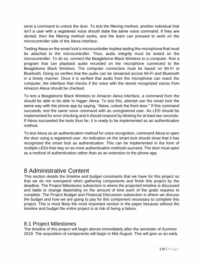
118 | P a g e
send a command to unlock the door. To test the filtering method, another individual that
isn’t a user with a registered voice should state the same voice command. If they are
denied, then the filtering method works, and the team can proceed to work on the
microcontroller side of the Alexa interface.
Testing Alexa on the smart lock’s microcontroller implies testing the microphone that must
be attached to the microcontroller. Thus, audio integrity must be tested on the
microcontroller. To do so, connect the Beaglebone Black Wireless to a computer. Run a
program that can playback audio recorded on the microphone connected to the
Beaglebone Black Wireless. The computer connection must be based on Wi-Fi or
Bluetooth. Doing so verifies that the audio can be streamed across Wi-Fi and Bluetooth
in a timely manner. Once it is verified that audio from the microphone can reach the
computer, the interface that checks if the voice with the stored recognized voices from
Amazon Alexa should be checked.
To test a Beaglebone Black Wireless to Amazon Alexa interface, a command from the
should be able to be able to trigger Alexa. To test this, attempt use the smart lock the
same way with the phone app by saying, “Alexa, unlock the front door.” If this command
succeeds, test the same voice command with an unregistered user. An LED should be
implemented for error checking and it should respond by blinking for at least two seconds.
If Alexa succeeded the tests thus far, it is ready to be implemented as an authentication
method.
To test Alexa as an authentication method for voice recognition, command Alexa to open
the door using a registered user. An indication on the smart lock should show that it has
recognized the smart lock as authentication. This can be implemented in the form of
multiple LEDs that stay on as more authentication methods succeed. The door must open
as a method of authentication rather than as an extension to the phone app.
8 Administrative Content This section details the timeline and budget constraints that we have for this project so that we do not overspend when gathering components and finish this project by the deadline. The Project Milestones subsection is where the projected timeline is discussed and liable to change depending on the amount of time each of the goals requires to complete. The Project Budget and Financial Discussion subsection is where we discuss the budget and how we are going to pay for this component necessary to complete this project. This is most likely the most important section in the paper because without the timeline and budget the entire project is at risk of being a failure.
8.1 Project Milestones The timeline of this project will begin almost immediately after the semester of Summer 2019. The acquisition of components will begin in Mid-August. This will give us an early

119 | P a g e
start on the project so that we can test the components and change them if necessary. The component acquisition will end at around late August and from that point on implementation of our Tier one goals will begin. The Tier one goals are the part of our project that must be functional on our Smart Lock regardless of the time. The target deadline for the Tier one is by Mid to Late September because we want the lock to be at least partially functional so that we can begin implementation of the Tier two goals.
If the Tier one goals are not complete by the end of September, the work will continue for
them while we begin the implementation of the Tier two goals concurrently so that we do
not completely fall behind on the construction of our Smart Lock. The target deadline for
both Tier one and Tier two goals to be integrated into our Smart Lock is the beginning of
November. The idea is that if there is any delay in the initial implementation of the tier one
goals, then the process for the tier goals should be split between the members of the
group. Two members will work on the tier one goals until completion and the other two
members will begin focusing on the tier two goals. Having the team focused and steadily
working on specific sections should be able to bring assistance with catching up to the
designated milestones.
This deadline will give our team enough time to troubleshoot and work on the integration
of our Tier three goal, the door camera. This goal alone may take the entire month to
integrate into our Smart Lock. Due to the complexity of the Tier three goal, the entire team
will need to be present to complete any additional research required to achieve this goal.
The complexity of the goal itself is why it is in the third tier and it requires a higher skill
level for the hardware and software integration. These Project Milestones are subject to
change as the work begins and we find out just how many manhours each goal will take,
but we optimistic that we can complete all our Tier one and Tier two goals in a timely
manner.
8.2 Project Budget and Financial Discussions This subsection contains two sections. The first section is the project budget where we discuss the limit that we are willing to pay for each item because one of the constraints of this project is to be low cost. The other section is the Financial Discussions where we discuss means by which we will finance this project.
8.2.1 Budget Evaluation The Budget of this project is always subject to change depending if components are required to change for the better of the project. The goal for this budget that the total costs for components will not exceed 200 dollars. Our budget is tight because we are an independent Senior Design project. Table 36 shows the cost of the components to be used.

120 | P a g e
Table 36: Tier 1 Component Cost
Component Price
Deadbolt lock $9.38
Door Frame TBD
Door Hinges $1.75
Capacitive Sensor $38.39
BeagleBone Black Board $62.50
3D-Printed Case TBD
Wires $4.99
RFID Scanner and Card $5.50
Servo Motors $5.95
Bluetooth Chip $48.48
PCB TBD
Table 36 only contains the components that are to be used for our Tier one goals. There are two item that are listed as TBD (to be determined), because these two components may not be added into the project or we may be able to acquire them for free. The Tier two and three goals require their own separate budget and table because they are deemphasized in this project and due to the tight time constraints, our group may not be able to start the integration of these goals. Table 37 is the table for those goals.
Table 37: Tier 2 Component Cost
Component Price
Door Camera $37.99
Accelerometer Chip $7.99
Wireless Keypad TBD
These are the current budgetary constraints for this project if necessary, they will change for the benefit of our project.
8.2.2 Financial Discussion As previously stated, our project is completely independent, thus we are self-funding the entire project. The total cost of the project will be split between our four teammates. We will also be acquiring certain components for free from the UCF Robotics club as well as some components that can be gathered from the office of one of our groupmates. These two factors will hopefully aid us in staying within our strict budget.
8.3 BOM Table 38 displays the Bill of Materials which is a breakdown of the devices being
purchased for this project. They will be separated by the vendor, the quantity, price per

121 | P a g e
item and the total price. It can be noted that the total cost of this project appears to be
$210.79 which is just over our estimated $200.00 budget. Unfortunately, this will leave
us with little room for mistake, but it is also not taking possible discounts into account.
Table 38: Bill of Materials
Component Quantity Price Per Total Source
Bluetooth V4.2 1 $6.50 $6.50 Cypress Semi
Servo Motor 1 $5.95 $5.95 Hobbyking
Beaglebone 1 $62.50 $62.50 GHI
Capacitive Fingerprint Sensor
1 $38.39 $38.39 Waveshare
RFID Scanner & Card
1 $34.95 $34.95 DLP Design
Accelerometer 1 $7.99 $7.99 Adafruit
AA Battery 2 $0.93 $1.86 Amazon
Door Hinge 1 $1.75 $1.75 Amazon
Deadbolt Lock 1 $9.38 $9.38 Amazon
3D Ink Spool 1 $16.00 $16.00 Amazon
AA Battery Holder
1 $1.60 $1.60 Amazon
Doorknob 1 $13.99 $13.99 Amazon
Red LED 2 $0.35 $0.70 SparkFun
Green LED 2 $0.35 $0.70 SparkFun
MAX603 Voltage Reg
1 $6.79 $6.79 Mouser
PFET 1 $0.80 $0.80 Digikey
Total $210.79
9 Final Design Discussion This design started off as with just a few simple features that we found tutorials for online and were going to tie them together and evolved into a new project that carries inspiration from those online tutorials as well as the Smart-Locks that are currently available on the market. This evolution was necessary to provide a challenge for our team. the implementation of each of these features has their own coding and hardware challenges. An example would be how we plan on to allow each of the forms of entry to make the door unlock without must enter each form. Another challenge would be the implantation of the Auto-Unlocking feature, although we do have the model from the August Smart-Lock to use a reference for our design. These challenges for implementation provide us an opportunity to learn so that we can learn from this project.
The design of this project required several hours of research and comparisons between a variety of other projects that were made previously. The different designs were

122 | P a g e
combined, and the concepts witnessed within them were used to create the overall design of the project. A challenge that came with the design was that not every part initially planned for the product was compatible. Further research was required to replace the incompatible parts with devices that improved the efficiency of the design. Several aspects of different parts needed to be observed for part choices, some of which include the operating voltage and operating temperature. The operating voltage could not pass over a certain value or else the efficiency of the product itself will be reduced. This was a challenge due to the fact that more powerful devices required a higher operating voltage to function. We also needed to carefully pick parts that had operating temperatures that fall within average temperatures that are experienced outside. This limited us from using parts that involved simpler materials that could be easily damaged. Another challenge that would be experienced in this project was finding all of the pieces while remaining within an ideal budget. Finding parts that were efficient and durable while being cost effective was another challenge that was encountered. Finding these compatible parts was another part of the design that required its own time and research to be placed.
To achieve a final design, it is necessary to simulate the different connections required
for this project and measure the voltage and current for every individual part. Once every
value was ideal, then the next step is to test the same values on a breadboard to make
sure the connections are correct in a “real world” setting. By this point in the design
process, any modifications or improvements must be completed before the design is
taken to the next step. Once the breadboard is set up, then all of the values must be
measured again to confirm that the product is functional. The final step will be to make
the same connections onto a printed circuit board and perform the same checks. After
the programming is set and the PCB is completed, the next step for the design is to mount
it onto the casing.
After some research it was concluded that the best option to take was to 3D print the
casing for this product. Research was then performed into the dimensions of the different
devices that will be implemented into the smart lock. After some calculations and
modifications, the overall size of the casing was made and the thickness needed to reflect
the thickness of a door. The next step would be to be able to place the printed circuit
board within the casing. Then, spaces and gaps would be necessary to be made on the
surface of both sides of the casing in order to allow placements of the batteries, fingerprint
sensor, RFID sensor and the keypad. The final testing would be to test this prototype to
make sure that all of its features are functional and that it is a successful product.

A | P a g e
10 Appendices 10.1 Appendix A – References Datasheets:
Keypad: https://cdn.sparkfun.com/assets/7/e/f/6/f/sparkfun_keypad.pdf
Capacitive Fingerprint Sensor:
https://www.waveshare.com/w/upload/8/82/Capacitive_Fingerprint_Reader_User_Manual_EN.pdf
Bluetooth V4.2 PSOC: https://www.cypress.com/file/416481/download
MAX603 Voltage Regulator: https://datasheets.maximintegrated.com/en/ds/MAX603-MAX604.pdf
Accelerometer:
https://www.st.com/content/ccc/resource/technical/document/datasheet/3c/ae/50/85/d6/b1/46/fe/C
D00274221.pdf/files/CD00274221.pdf/jcr:content/translations/en.CD00274221.pdf
Beaglebone Board: https://cdn.sparkfun.com/datasheets/Dev/Beagle/OSD335x-Datasheet.pdf
DLP-RFID2: https://www.dlpdesign.com/dlp-rfid2-ds-v113.pdf
Smartlock With Cloud Connectivity: http://www.ti.com/lit/ug/tidue59/tidue59.pdf
Smartlock with 4x AA Batteries: http://www.ti.com/lit/ug/tidubv3c/tidubv3c.pdf
10.2 Appendix B – Copyright Permissions August Smart-Lock
Kwiset
Beaglebone Black Wireless
https://github.com/beagleboard/beaglebone-black-wireless/blob/master/LICENSE
a. License grant.
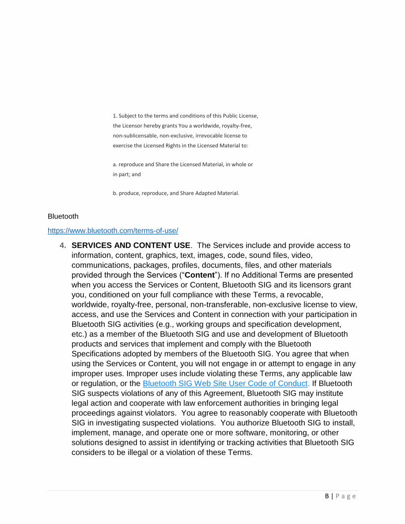
B | P a g e
1. Subject to the terms and conditions of this Public License, the Licensor hereby grants You a worldwide, royalty-free, non-sublicensable, non-exclusive, irrevocable license to exercise the Licensed Rights in the Licensed Material to: a. reproduce and Share the Licensed Material, in whole or in part; and b. produce, reproduce, and Share Adapted Material.
Bluetooth
https://www.bluetooth.com/terms-of-use/
4. SERVICES AND CONTENT USE. The Services include and provide access to
information, content, graphics, text, images, code, sound files, video,
communications, packages, profiles, documents, files, and other materials
provided through the Services (“Content”). If no Additional Terms are presented
when you access the Services or Content, Bluetooth SIG and its licensors grant
you, conditioned on your full compliance with these Terms, a revocable,
worldwide, royalty-free, personal, non-transferable, non-exclusive license to view,
access, and use the Services and Content in connection with your participation in
Bluetooth SIG activities (e.g., working groups and specification development,
etc.) as a member of the Bluetooth SIG and use and development of Bluetooth
products and services that implement and comply with the Bluetooth
Specifications adopted by members of the Bluetooth SIG. You agree that when
using the Services or Content, you will not engage in or attempt to engage in any
improper uses. Improper uses include violating these Terms, any applicable law
or regulation, or the Bluetooth SIG Web Site User Code of Conduct. If Bluetooth
SIG suspects violations of any of this Agreement, Bluetooth SIG may institute
legal action and cooperate with law enforcement authorities in bringing legal
proceedings against violators. You agree to reasonably cooperate with Bluetooth
SIG in investigating suspected violations. You authorize Bluetooth SIG to install,
implement, manage, and operate one or more software, monitoring, or other
solutions designed to assist in identifying or tracking activities that Bluetooth SIG
considers to be illegal or a violation of these Terms.

C | P a g e
SparkFun License of Use for Keypad Schematic
Figure 8 Licensed Under CC BY 2.0
Cypress Content Terms for Use of Property

D | P a g e
Copyright From Cypress Datasheet
10.3 Appendix C – List of Tables and Figures
10.3.1 Tables 1. Table 1: Engineering Requirement Specifications
2. Table 2: Size and Power Constraints 3. Table 3: Project Budget
4. Table 4: Competitors’ Selling Price 5. Table 5: Senior Design 1 Milestones
6. Table 6: Senior Design 2 Milestones 7. Table 7: Fingerprint Sensor Comparison
8. Table 8: RFID Sensor Comparison
9. Table 9: Keypad Comparison 10. Table 10: Bluetooth Module Comparison
11. Table 11: Motor Driver Specs 12. Table 12: Accelerometer Specs
13. Table 13: Duracell Specs 14. Table 14: Power Supply Specs
15. Table 15: Voltage Regulator Specs 16. Table 16: Power Monitor Specs
17. Table 17: MOSFET Specs 18. Table 18: Arduino MKR WiFi 1010 Technical Specifications
19. Table 19: Raspberry Pi 3 Model B Technical Specifications
20. Table 20: Beaglebone Black Wireless Technical Specifications
21. Table 21: TI LAUNCHXL-CC2650 Technical Specifications 22. Table 22: Stepper Physical Specs
23. Table 23: Stepper Electrical Specs 24. Table 24: DC Motor Specs
25. Table 25: Bluetooth Design Specs 26. Table 26: RFID Specs

E | P a g e
27. Table 27: Fingerprint Sensor Specs
28. Table 28: Fingerprint Sensor Labels 29. Table 29: LIS3DH Pin-Out
30. Table 30: Module Dimensions 31. Table 31: Bluetooth Transmitter Classification
32. Table 32: Authentication Testing Delegation 33. Table 33: Application Testing Delegation
34. Table 34: Authentication Test Procedures 35. Table 35: Application Test Procedures
36. Table 36: Tier 1 Component Cost 37. Table 37: Tier 2 Component Cost 38. Table 38: Bill of Materials
10.3.2 Figures 1. Figure 1: House of Quality 2. Figure 2: Keyless Entry Block Diagram
3. Figure 3: August Smart Locks 4. Figure 4: Schlage Smart Lock
5. Figure 5: Kwikset Smart Locks
6. Figure 6: TI Smart Lock Block Diagram 7. Figure 7: TI Smart Lock with 4x AA Batteries Block Diagram
8. Figure 8: SparkFun Keypad 9. Figure 9: Sparkfun Keypad 1568-1856-ND Schematic
10. Figure 10: Bluetooth Schematic
11. Figure 11: Variable PWM Controlled Servo Position
12. Figure 12: Transistor States 13. Figure 13: Reverse Polarity Protection Circuit
14. Figure 14: L2CAP Architectural Block Diagram 15. Figure 15: LE Pairing Phases
16. Figure 16: Bluetooth LE Link Layer State Machine 17. Figure 17: Advanced Encryption Standard Algorithm
18. Figure 18: Overall System Diagram 19. Figure 19: Power Distribution System
20. Figure 20: Bluetooth Communication Design 21. Figure 21: RFID Security Measures
22. Figure 22: User Interface System Diagram
23. Figure 23: Motor Functionality Block Diagram
24. Figure 24: Keyless Entry Architecture 25. Figure 25: Sensor Logic Class Diagram
26. Figure 26: Hardware Block Diagram 27. Figure 27: Servo Configuration
28. Figure 28: RFID Design Schematic 29. Figure 29: Fingerprint Sensor Connections

F | P a g e
30. Figure 30: LIS3DH Schematic
31. Figure 31: MIC5225-3.3 Linear Voltage Regulator 32. Figure 32: Accelerometer Pull-up Resistors
33. Figure 33: LIS3DH Connectors 34. Figure 34: Potential Voltage Sources
35. Figure 35: Beaglebone Schematic 36. Figure 36: Polarity Protection Schematic
37. Figure 37: Voltage Regulator Schematic 38. Figure 38: Keypad Connection Schematic
39. Figure 39: Motor Door Mount 40. Figure 40: Motor Mount