keyless entry adding an after market keyless …keyless entry adding an after market keyless entry...
TRANSCRIPT
KEYLESS ENTRY ADDING AN AFTER MARKET KEYLESS ENTRY TO THE 3000gt
By Tom Heany I thought it might be fun to implement a remote entry system on my 1991 3000gt VR4. I bought this car in the winter of 1992 and I very fond of it. Yep, there are a few things I don’t like; the TD04-9b, the lack of keyless entry, the popups, but it’s the longest serious relationship I’ve ever had with a woman. Oops, I mean car.
None of the 91s and very few of the first Gens had remote openers. When I had the interior out of the car to install a backup camera. I discovered it didn’t even have a wiring harness that supports a keyless entry. I decided the Keyless entry was a pretty easy modification. Being an engineer, I do drawings and notes for every mod I make to the car. This is my attempt at a do it yourself article based on my drawings and notes. The skills necessary are basic and the cost are very low. I spent less then $10.00.
While this article is aimed at the 1st Gens, it is easily adaptable to most of the 3000gt/Stealth’s. Especially if you don’t
have the factory anti-theft / alarm system (ETACS).
In the past few years there has been a flood of cheap electronics coming out of China. The low cost of these is nothing but amazing. The EBAY vendor I bought the remote receiver from included two keychain remotes for a total cost of $7.88. The wireless receiver comes complete and the key fobs are pre-programed to the wireless
The wireless receiver is connected to the car at two points: the Door Lock Relay and the ETACS control unit. I also took the 12 volt DC power from the Door Lock Relay, mostly because I wanted the whole system on the same fuse. The Door Lock Relay is where we connect to lock and unlock the door. The ETACs unit is the security unit for the car. We make two connections here, one to disable the alarm and one to set it off (to help find the car in the parking lot). Because the second button disables the alarm and opens the door, I included a diode on the ETACS connection to avoid feedback. Needless to say, if you don’t have the factory alarm, don’t do the connections to the ETACS.
Materials:
1N4001 ¼ Watt diode. I bought a bunch of these at Radio shack in the ‘70s. Just about any ¼ Watt diode will work.
.
A dozen or so vampire taps. Personally I soldered and used heat shrink on everything but I’m Retired and have time.
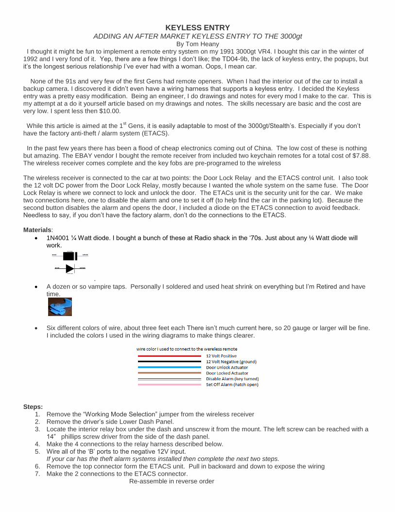
Six different colors of wire, about three feet each There isn’t much current here, so 20 gauge or larger will be fine. I included the colors I used in the wiring diagrams to make things clearer.
Steps:
1. Remove the “Working Mode Selection” jumper from the wireless receiver 2. Remove the driver’s side Lower Dash Panel. 3. Locate the interior relay box under the dash and unscrew it from the mount. The left screw can be reached with a
14” phillips screw driver from the side of the dash panel. 4. Make the 4 connections to the relay harness described below. 5. Wire all of the ‘B’ ports to the negative 12V input.
If your car has the theft alarm systems installed then complete the next two steps. 6. Remove the top connector form the ETACS unit. Pull in backward and down to expose the wiring 7. Make the 2 connections to the ETACS connector.
Re-assemble in reverse order

12V 4CH Channel 315Mhz Wireless Remote Control Switch
From EBAY
Instructions to add more remotes: 1. Press and release the learning code button. Press any button on the remote. The blue LED will flash twice. The wireless receiver can remember up to 12 remotes. 2. To clear the wireless receivers memory, press and hold the learning code button for 8 seconds. Configuration: For the purpose of this project. Take off the jumper labeled “Working Mode Selection”
*There are lots of folks that sell these on eBay and Amazon If you type in the description
several will pop up. The eBay vendor I used was “Ynaan”
Key Fob Functions
rem
ove
Lock Door Unlock Door and Disable Alarm (This does not set the alarm) ( If alarm is set) Set off Alarm Mute Spouse (If alarm is set) (not yet implemented)

Remove the driver-side lower dash
Remove the two phillips screws in the hood lock release handle. Slide the handle and its bracket to you (toward the back of the car) to slide the mounting tab out of its slot. Take the release cable off the handle. Pry under the edge of the rheostat garnish using a thin, wide, strong-yet-flexible tool. You can use a professional trim removal tool or make one yourself. Slotted screwdrivers are typically too thick to easily slide under the edge of the garnish. Pull the rheostat assembly out a little and disconnect the rheostat connector first. Then disconnect the remote mirror switch connector. Pry under the edge of switch garnish B and then pull the assembly out a little. Disconnect the electrical connectors. Remove the two brass 10-mm bolts that are at the lower two corners of the knee protector. Remove the two black 10-mm bolts that are accessed from the opening where the two switch assemblies were. Pull the knee protector panel off.
1. Remove the bolts behind them.
2. Remove the 2 bolts near the floor on the knee panel.

Remove the 2 screws holding the “Interior Relay Box” to the firewall
Red wire from 12V supply
on pins 2 or 7 to 12V
positive input in the
wireless receiver.
Brown wire from pin 4 to
door lock function on first
‘A’ terminal
Blue wire on pin 8 to door
unlock function on second
‘A’ terminal. The second
‘A’ terminal will also be
connected to the White
wire coming from the
ETACS to disarm the
alarm.
The Black wire from pin 5
is connected to the
negative 12V input and
jumpered the first three
‘B’ terminals
If you don’t have a
security system, then you
are done. Reassemble
the car.
The left screw can be reached with a
14” phillips screw driver from the side
of the dash panel. The right hand
screw can be reached at an angle
from beneath the dash.
When you have the Interior Relay Box loose, work it over toward the center of the foot well where you can reach the wires. It might help to take the bottom nut off the bottom of the fuse box.


The Security Alarm Systems “ETACS”
1 Light green-black
2 Red-yellow
Headlight activation
3 brown-blue
Power lock
4 5 gray-yellow
defogger
6 black
7 Black-white
8 Yellow black
9 Red-gray
Driving lights
10 Red-green
Door open
11 Blue-black
12 Blue-red
defogger
13 Brown-yellow
LH door state (locked)
14 Brown
RH door state (locked)
15 Light green
16
17 Blue-white
trunk state
remote’s pink wire
18 Blue-black
Hood state
191 Light green
Door key rotation
20 Blue-red
trunk key rotation
remote’s white wire
ETACS 20 pin connector (C-65)
If you don’t have a security system skip the whole ETACS connection (steps 6 & 7).
When opening the door with the remote you must first disable the alarm. The ETACS unit is the security alarm for the 3000GT. It is located behind the drives side lower dash panel. The ETACS unit has two connectors on the side. The upper one is a 20 pin connector C-65. We use two lines on the C-65 connector. The pin 17 is the hatch open. Pin 17 is grounded to make the alarm go off, if the alarm is set. Pin 20 detects the key tuning in the hatch lock. We bring this to ground to disable the alarm (if set). Pin 20 and the unlock function from the lock relay are tied together so the alarm goes off when the entry system opens the door. Because the open and disarm lines are tied together, to keep the signals separate they are separated by a diode.
Diagram showing the connection of the ETACS to the wireless controller.

The blue white wire on pin 17 of the ETACS connector is connected the third ‘A’ terminal on the wireless remote. This
enables you to set off the alarm if the alarm is set.
The Blue red wire on pin 20 of the ETACS connect is connected with white wire containing a diode to the second ‘A’
terminal on the wireless receiver. It shares this connection with the door unlock function (the blue wire rom the relay).

On this diagram the ETACS unit is referred too as the “ECU”
[Type a quote from the document or the summary of an
interesting point. You can position the text box anywhere in
the document. Use the Drawing Tools tab to change the
formatting of the pull quote text box.]

Combined wiring Diagram showing all connections to the ETACS and the Door Lock Relay
References and thanks too: Mitsubishi Motors Corporation 3000GT Service Manual Dave Black’s 3000GT/Stealth Resource Jeff Lucius – Stealth 316