service manual valor 1000 scales - american …...service manual valor 1000 scales ohaus corporation...
TRANSCRIPT

SERVICE MANUAL Valor
™ 1000 Scales
Ohaus Corporation 19A Chapin Road, P.O. Box 2033, Pine Brook, NJ 07058-2033 (973) 377-9000


SERVICE MANUAL
Valor™ 1000 Scales
The information contained in this manual is believed to be accurate at the time of publication, but Ohaus Corporation assumes no liability arising from the use or misuse of this material. Reproduction of this material is strictly prohibited. Material in this manual is subject to change. © Copyright 2008 Ohaus Corporation, all rights reserved. TM Registered trademark of Ohaus Corporation.


TABLE OF CONTENTS
Page No. CHAPTER 1 GETTING STARTED
1.1 Introduction ................................................................................................................1-1 1.2 Service Facilities........................................................................................................1-1 1.3 Tools and Test Equipment Required .........................................................................1-2 1.4 Specifications.............................................................................................................1-2 1.5 Scale Operation .........................................................................................................1-3
1.5.1 Overview of the Controls ....................................................................................1-3 1.5.2 Power On ...........................................................................................................1-4 1.5.4 Power Off ...........................................................................................................1-4
CHAPTER 2 TROUBLESHOOTING
2.1 Troubleshooting .........................................................................................................2-1 2.2 Diagnostic Guide .......................................................................................................2-1
2.2.1 Diagnosis............................................................................................................2-1 2.2.2 Checking Load Cells for Trouble ........................................................................2-1 2.2.3 Diagnostic Guide ................................................................................................2-4
CHAPTER 3 MAINTENANCE PROCEDURES
3.1 Preventive Maintenance ............................................................................................3-1 3.1.1 Preventive Maintenance Checklist .....................................................................3-1
3.2 Service Strategy ........................................................................................................3-1 3.3 Opening the Scale .....................................................................................................3-1
3.2.1 Separating the Top and Bottom Housings..........................................................3-2 3.4 Removing/Replacing the Main PCB and Switches PCB............................................3-3 3.5 Removing/Replacing the Load Cell ...........................................................................3-4 3.6 Setting the Overload Stops........................................................................................3-5 3.7 Removing/Replacing the Battery ...............................................................................3-6 3.8 Replacing the Fuse....................................................................................................3-6 3.9 Replacing the Function Label ....................................................................................3-6
CHAPTER 4 TESTING
4.1. Testing .......................................................................................................................4-1 4.1.1 Test Masses Required .......................................................................................4-1
4.2 Operational Test ........................................................................................................4-1 4.3 Segment Display Test................................................................................................4-1 4.4. Performance Tests ....................................................................................................4-2
4.4.1 Precision Test.....................................................................................................4-2 4.4.2 Repeatability Test...............................................................................................4-3 4.4.3 Linearity Test......................................................................................................4-5 4.4.4 Off-Center Load Test..........................................................................................4-5 4.4.5 Adjusting Off Center Load ..................................................................................4-6
CHAPTER 5 DRAWINGS AND PARTS LISTS
5-1 Valor 1000 Scales: Housing & Internal Parts.............................................................5-2
Appendix A STANDARD CALIBRATION A.1 Calibration................................................................................................................. A-1 A.2 Setup and Calibration .................................................................................................!-2
Ohaus Corporation www.ohaus.com i Valor™ 1000 Series Service Manual
TABLE OF CONTENTS
LIST OF TABLES
TABLE NO. TITLE Page No. 1-1 Specifications (Standard Models)..........................................................................1-2 1-2 Specifications (NTEP Models)...............................................................................1-3 1-3 Functions of Display Controls................................................................................1-4 2-1 Load Cell Resistance Readings (in Ohms) ...........................................................2-2 2-2 Color Code for Load Cell Wiring............................................................................2-2 2-3 Load Cell Output Readings (in mV with 5V Excitation) .........................................2-3 2-4 Diagnostic Guide...................................................................................................2-2 3-1 Mounting Bolt Torque Settings..............................................................................3-4 3-2 Valor 1000 Overload Stop Gap Settings ...............................................................3-5 4-1 Calibration Mass Values........................................................................................4-1 4-2 Repeatability Worksheet .......................................................................................4-4 4-3 Linearity Test Masses ...........................................................................................4-5 5-1 Valor 1000 Scales: Housing & Internal Parts ........................................................5-3 A-1 Initial Configuration Settings for Each Model ....................................................... A-2
LIST OF ILLUSTRATIONS FIGURE NO. TITLE 1-1. Valor 1000 Control Panel ......................................................................................1-4 1-2 Strain Gauge Load Cell .........................................................................................1-5 1-3 Downward force on the Platform bends the beam ................................................1-5 1-4 Route of electrical Load Cell input and output through Wheatstone Bridge..........1-6 2-1 Load Cell wire connections to Main PCB ..............................................................2-3 3-1 Valor 1000 Bottom ................................................................................................3-2 3-2 Top and Bottom Housings.....................................................................................3-2 3-3 Removing bolts holding Frame to the Load Cell ...................................................3-4 3-4 Overload stops on Valor 1000...............................................................................3-5 3-5 Gap position of corners A, B,C, D .........................................................................3-5 3-6 Rechargeable battery............................................................................................3-6 4-1 Segment Display ...................................................................................................4-1 4-2 Scale drawing of Valor 1000 Load Cell and Weighing Pan...................................4-6 5-1 Valor 1000 Scales: Housing & Internal Parts ........................................................5-2 A-1 Main PCB’s Menu Lock Jumper must be ON to calibrate .................................... A-1
Valor™ 1000 Series Service Manual ii Ohaus Corporation www.ohaus.com

CHAPTER 1 GETTING STARTED
1.1 INTRODUCTION
This service manual contains the information needed to perform routine maintenance and service on the Ohaus Valor 1000 Series scales. Familiarity with the scale’s Instruction Manual is assumed. The contents of this manual are contained in five chapters:
Chapter 1 Getting Started – Contains information on service facilities, tools and test equipment, specifications, and the mechanical and electronic functions of the scale.
Chapter 2 Troubleshooting – Contains a diagnostic guide and error code table.
Chapter 3 Maintenance Procedures – Contains preventive maintenance procedures and disassembly, repair and replacement procedures.
Chapter 4 Testing – Contains a list of required test masses, an operational test, segment display test, performance tests and adjustments.
Chapter 5 Drawings and Parts Lists – Contains exploded views of Valor 1000 scales identifying all serviceable components.
Appendix A Standard Calibration – Explains procedures for Standard Calibration, performed prior to using a scale, and after service.
1.2 SERVICE FACILITIES
To service a scale, the service area should meet the following requirements:
• Should be temperature controlled and meet scale specifications for temperature environmental requirements.
• Must be free of vibrations such as fork lift trucks close by, large motors, air currents or drafts from air conditioning/heating ducts, open windows, people walking by, fans, etc.
• Area must be clean and free of excessive dust.
• Work surface must be stable and level.
• Scale must not be exposed to direct sunlight or radiating heat sources.
• Use an approved Electro-Static Device
Valor™ 1000 Series Service Manual 1-1 Ohaus Corporation www.ohaus.com

CHAPTER 1 GETTING STARTED
1.3 TOOLS AND TEST EQUIPMENT REQUIRED
1. Common hand tools
2. Standard electronics tool kit
3. Digital Voltmeter (DVM) capable of reading from 1 mv to 50 V dc.)
1.4 SPECIFICATIONS
Complete specifications for the Ohaus Valor 1000 Scales are listed in Table 1-2. When a scale has been serviced, it must meet the specifications listed in the table. Before servicing the scale, determine what specifications are not met.
TABLE 1-1. SPECIFICATIONS
Model V11P3 V11P6 V11P15 V11P30
Capacity x Readability Max x d (non-approved)
3 kg x 0.0005 kg3000 g x 0.5 g
6.6 lb x 0.001 lb105 oz x 0.02 oz
6 kg x 0.001 kg 6000 g x 1 g
13 lb x 0.002 lb 210 oz x .05 oz
15 kg x 0.002 kg 15000 g x 2 g 33 lb x 0.01 lb
520 oz x 0.1 oz
30 kg x 0.005 kg 30000 g x 5 g 66 lb x 0.02 lb
1058 oz x 0.5 oz
Max displayed resolution 1:7500d
Linearity ±2d
Off Center Load error ±2d
Repeatability ±2d
Hysteresis ±2d
Zero drift vs. temp. ±2 d / oC
Span drift vs. temp. ±2d / °C
Tare Range To Full Capacity by Subtraction
Stabilization Time ≤ 3 seconds
Auto Zero Tracking User selectable from 0.1d to 2d
Operating Temp. range 0° to 40°C / 32° to 104°F
Storage Temp. range -10° to 60°C / 14° to 140°F
Humidity Range ≤90% relative humidity, non-condensing
Power 9VDC 700mA AC adapter / Internal rechargeable sealed lead acid battery
Battery Life 80/100 hours (with/without backlight on)
Pan Size (mm/in) 250 x 180 / 9.9 x 7.1
Ohaus Corporation www.ohaus.com 1-2 Valor™ 1000 Series Service Manual

CHAPTER 1 GETTING STARTED
1.5 SCALE OPERATION
This section contains information on the basic operation of the scale. Units of measure indicators: pieces (not used), pounds, ounces, Kilograms 1.5.1 OVERVIEW OF THE CONTROLS
7-segment, 6-digit backlit LCD
Low Battery Indicator
Battery Charge Indicator
Level Bubble
Control Buttons Figure 1-1. Valor 1000 Control Panel. Center of Zero,
NET, Stability, & Sum icons
TABLE 1-3. FUNCTIONS OF DISPLAY CONTROLS
Button Action Function
Short Press Sets display to zero ZERO (Enter) Menu Press Confirms settings
Short Press Tares weight of item on pan TARE ( ) Menu Press Decrement over and under settings ( )
Short Press Stores displayed weight in accumulation memory. (Displays accumulation data when display is at zero.)
Menu Press Increment over and under settings ( )
M+ Units
( )Long Press Change unit of measure while long-pressing SELECT button
Short Press When setting over and under values, shift to next digit
SELECT Units
( ) Menu Press Change unit of measure with short press of M+
1.5.2 Power ON/OFF
To turn the scale on, flip the toggle switch on the bottom-right of the Housing. The scale performs a display test, momentarily displays software version, and then enters the active weighing mode. To turn the scale off, toggle the same switch to the off position.
The Valor 1000 can operate on either AC Power, with the included AC adapter, or on the internal rechargeable battery. The scale automatically switches to battery operation if power fails while the scale is on.
Before using the scale for the first time, the battery should be fully charged for up to 12 hours. During charging, the battery Charge indicator remains lit. The scale can be operated during charging. The battery is protected against over-charging and the scale can remain connected to the AC power line.
Valor™ 1000 Series Service Manual 1-3 Ohaus Corporation www.ohaus.com

CHAPTER 1 GETTING STARTED
1.6 HOW LOAD CELLS OPERATE
Load Cells are devices that convert force into a signal. The Valor 1000 has a Strain Gauge Load Cell, which is made from a metal beam with holes drilled in it. Strain gauges are affixed to the beam at the top and bottom to measure changes in the beam due to deflection. The gauges are bonded very securely to the metal, where they sense very small deflections in the metal caused by the load being applied to the cell. Because the signal levels are very small, the circuit is protected from all outside influences such as moisture, physical damage, or electrical interference.
Figure 1-2. Strain Gauge Load Cell.
The strain gauges are wired into a Wheatstone Bridge Circuit. (See Figure 1-3.)
Figure 1-3. Downward force on the Platform bends the beam, causing two gauges to stretch
and two to compress in opposition, changing the electrical resistance of the circuit.
At zero load, all strain gauges are unstressed. Weight placed on the Platform bends the beam, causing two gauges to stretch and two to compress in opposition, changing the electrical resistance of the circuit.
Force
Strain Gauges
Holes drilled in Strain Gauge Load Cell
Attachment points to Platform
Wheatstone Bridge Circuit
Strain Gauge Strain Gauge
–
– Strain Gauge
+ Strain Gauge
+
Beam
Printed Circuit Board completing Wheatstone Bridge circuit
Ohaus Corporation www.ohaus.com 1-4 Valor™ 1000 Series Service Manual

CHAPTER 1 GETTING STARTED
1.6 HOW LOAD CELLS OPERATE
The difference in the output signal before and after the mass was placed on the platform is taken, interpreted and displayed.
Figure 1-4. Route of electrical Load Cell input and output through Wheatstone Bridge circuit.
A Load Cell is a force sensor, which receives a voltage (excitation) from a regulated power source in the Indicator, and sends back a low-voltage milli-volt (mV) relative to the force applied. The Load Cell signal is read by the Indicator, which converts it to a numeric value and shows it visually. This output value increases as weight is loaded to the Load Cell.
For example, a 500kg Load Cell with 2mV/V output and 5V excitation would have a change of 0.02mV per kg change in the load, that is, 10mV/500=0.02mV per kg. At a load of 250kg the signal voltage would thus increase by 5mV from the value measured at no load.
Tension
Tension
Compression
Compression
+Excitation (Supply)
–Excitation (Supply)
INPUT(volts) LOADCELL 2 mV/V
Strain Gauges
4 strain gauges connected as a Wheatstone Bridge
OUTPUT (milli volts) +Sig
–Sig
Valor™ 1000 Series Service Manual 1-5 Ohaus Corporation www.ohaus.com

CHAPTER 1 GETTING STARTED
Ohaus Corporation www.ohaus.com 1-6 Valor™ 1000 Series Service Manual

CHAPTER 2 DIAGNOSTIC GUIDE
2.1 TROUBLESHOOTING
This section of the manual contains troubleshooting information. Information is contained to isolate specific problems using Table 2-1, Diagnostic Guide. Follow all directions step by step. Make certain that the work area is clean. Handle scale components with care. Use appropriate Electro-Static Device.
2.2 DIAGNOSTIC GUIDE
Table 2-1 is a Diagnostic Guide designed to help locate the problem area quickly and easily. The probable causes are listed with the most common cause first. If the first remedy does not fix the problem, proceed to the next remedy. Before attempting to repair the scale, read all chapters of this manual to be familiar with the scale components and operation.
2.2.1 Diagnosis
1. Isolate and identify the symptom
2. Refer to Table 2-1, Diagnostic Guide and locate the symptom.
3. Follow the suggested remedies in the order they appear.
4. Perform the indicated checks, or see the appropriate section of the manual.
5. Repair or replace the defective section of the balance.
NOTE: If more than one symptom is observed, approach one area at a time, and remember that the symptoms may be interrelated.
If a problem arises that is not covered in this manual, contact Ohaus Corporation for further information.
2.2.2 Checking Load Cells for Trouble
1. Visual Check:
– Clean the unit before evaluating any mechanical problems. In some cases, debris may have accumulated inside the Housing. Make sure there is no buildup of any foreign material.
– Examine the unit for bent Frame or signs of physical abuse that could cause it to malfunction. Replace all damaged parts. See Chapter 5 for parts identification.
– Check that the Down Stops are not touching the Frame. This would restrict movement, causing improper operation. If the Down Stops are improperly set, adjust them. (See Section 3.6.)
– Check the cables leading to the Load Cell for cuts, abrasions or other signs of excessive wear and tear.
– Check for a bent or twisted Load Cell: Place the top surface and then each of the sides of the Load Cell on a flat surface, to see if it rests flat and even. A gap indicates a bent or twisted Load Cell. A Load Cell that is even slightly bent or corroded should be replaced.
– Examine the Load Cell for corrosion due to high humidity or exposure to chemicals.
Valor™ 1000 Series Service Manual 2-1 Ohaus Corporation www.ohaus.com

CHAPTER 2 DIAGNOSTIC GUIDE
2.2.2 Checking Load Cells for Trouble
2. Perform a Resistance Test, to determine if the Load Cell is severely damaged or a short circuit to the frame has occurred. (See Chapter 4 for details.)
Note: The Load Cell must be completely disconnected from the Printed Circuit Board and at no load when the resistance readings are taken.
Using an ohm meter, measure and record resistance between each pair of wires from the Load Cell, as specified in Table 2-1. Compare the measured readings with the specified values in Table 2-1.
If the resistance readings are in the range specified, skip to the next section. If they are outside the expected range, open circuit or short-circuit across any two wires, the Load Cell is defective: replace it. (See Chapter 3.)
TABLE 2-1. LOAD CELL RESISTANCE READINGS (in Ohms)
Models Ex+ to Ex– S+ to S– Ex+ to S– Ex+ to S+ Ex– to S+ Ex– to S–
V11P3 404 ± 10 350 ± 4 289 ± 10 289 ± 10 289 ± 10 289 ± 10
V11P6 404 ± 10 350 ± 4 289 ± 10 289 ± 10 289 ± 10 289 ± 10
V11P15 404 ± 10 350 ± 4 289 ± 10 289 ± 10 289 ± 10 289 ± 10
V11P30 404 ± 10 350 ± 4 289 ± 10 289 ± 10 289 ± 10 289 ± 10 3. Perform an Output Voltage Test: Measure the no load, 50% load and full load
output. The reading should meet the Load Cell specifications. The Load Cell output should be very close to linear over its capacity range.
NOTE: The following steps involve power applied to the scale. Load Cell solder contacts can be used as measuring points. See Figure 2-1.
The EXE+ and EXE– wires should be connected to the PCB, and the SIG+ and SIG– wires should be disconnected. Record the colors for each wire connection before disconnecting. (See Table 2-2 for typical color code for Valor 1000.)
TABLE 2-2. COLOR CODE FOR LOAD CELL WIRING*
GREEN WHITE RED BLACK
EXE– EXE+ SIG+ SIG– *Color codes may vary.
– Insert the Platform Support into the Load Cell Frame, place the Platform on top, and turn on power to the scale.
– Using a voltmeter, measure and record the excitation voltage supplied to the PCB: with no load on the Platform, measure the voltage across points 3 and 4 of Load Cell connection on the PCB (+EXE and –EXE). This voltage must be approximately 5.0 Volts dc with the Load cell connected. If the voltage is lower, disconnect the Load Cell cable from the PCB and measure again. If the voltage is 5 Volts dc, the Load Cell is defective and must be replaced. If the voltage remains low, the PCB is defective and must be replaced.
Ohaus Corporation www.ohaus.com 2-2 Valor™ 1000 Series Service Manual

CHAPTER 2 DIAGNOSTIC GUIDE
2.2.2 Checking Load Cells for Trouble
Figure 2-1. Load Cell wire connections to Main PCB.
CAUTION: IN THE NEXT STEP, DO NOT OVERLOAD THE SCALE BEYOND FULL CAPACITY RATING.
– Measure the voltages on +SIG and –SIG wires, disconnected from PCB (points 1 and 2 in Figure 4-2). Note: Measurements must be made with these wires disconnected from the PCB. These measurements represent the output of the Load Cell. Record measurements at Zero Load, 50% and full scale capacities. See Table 2-3 for typical readings.
NOTE: Table 2-1 indicates typical readings. Actual values can vary, but should remain linear throughout the range. If readings are out of tolerance, replace the Load cell. (See Section 3.6.)
TABLE 2-3. LOAD CELL OUTPUT READINGS (in mV with 5V Excitation)
Model/Capacity Zero Load 50% Load 100% Load V11P3 / 3kg 1.5 ± 2.0 Zero + 4.1 Zero + 6.7
V11P6 / 6kg 0.9 ± 2.0 Zero + 3.4 Zero + 5.9
V11P15 / 15kg 0.6 ± 2.0 Zero ± 3.2 Zero ± 5.9
V11P30 / 30kg 0.3 ± 2.0 Zero + 2.8 Zero + 5.4
Valor™ 1000 Series Service Manual 2-3 Ohaus Corporation www.ohaus.com

CHAPTER 2 DIAGNOSTIC GUIDE
2.2.3 Diagnostic Guide TABLE 2-4. DIAGNOSTIC GUIDE
Symptom Possible Cause Remedy
Scale will not turn on.
No power to scale Battery power exhausted Adapter defective Input connector at rear of balance may be defective On/Off switch defective or actuating fingers on top housing defective. Main PC Board defective.
Verify connections and voltage. Connect power and charge battery. Check the AC adapter voltage output which should match the specified voltage on the adapter. If voltage is low or nonexistent, replace the AC adapter. If OK, Proceed. Open the balance. Leave the cable connected to the top housing. Reconnect the AC adapter to the balance. Check AC voltage at the input connector terminals. It should read 12 V AC. If voltage is not present, replace the input connector. If OK, proceed. (Caution: disconnect the AC adapter and remove power and/or batteries from the balance for this procedure, to prevent damage to the ohmmeter.) Open the balance. Using an ohm-meter, measure the resistance between the pins on the On/ Off switch. It should be open. If continuity is not present, replace the switch. Replace the Main PC Board.
Poor accuracy Unstable environment Balance out of calibration Balance was not re-zeroed before weighing.
Move scale to suitable location; insure that balance is level. Calibrate the balance. Press Zero with no weight on the pan, then weigh item.
Unable to calibrate Unstable environment Incorrect calibration mass Up and down stops out of adjustment. Load Cell defective.
Move scale to suitable location. Use correct calibration mass. Remove the cover from the load cell. Check the Overload Stops. (See Section 3.7.) If OK, the load cell is defective. Replace the Load Cell. (See Section 3.6.)
Ohaus Corporation www.ohaus.com 2-4 Valor™ 1000 Series Service Manual

CHAPTER 2 DIAGNOSTIC GUIDE
2.2.3 Diagnostic Guide
Symptom Possible Cause Remedy
Scale flashes Bat Battery discharged Connect power and charge battery.
Battery fails to charge fully
Battery is defective Replace battery.
-----H Overload during power on Remove weight from pan and re-zero. Calibrate
-----L Underload during power on Install pan and re-zero.
-Over- Weight on pan exceeds capacity
Remove weight from pan.
Err-1 Invalid under and over limit settings
Re-enter under and over limits. Calibrate the scale.
Valor™ 1000 Series Service Manual 2-5 Ohaus Corporation www.ohaus.com

CHAPTER 2 DIAGNOSTIC GUIDE
Ohaus Corporation www.ohaus.com 2-6 Valor™ 1000 Series Service Manual

CHAPTER 3 MAINTENANCE PROCEDURES
3.1 PREVENTIVE MAINTENANCE
Ohaus scales are precision instruments and should be carefully handled, stored in a clean, dry, dust-free area, and cleaned periodically. Follow these precautionary steps:
– When a scale has had chemicals or liquids spilled on it, all exterior surfaces should be cleaned as soon as possible with warm water on a damp cloth.
– Do not leave a mass on the scale when the scale is not in use.
– Allow time for the scale to stabilize after moving it from an area which is at a different temperature than the area where it is to be operated. Allow one hour for each 5°F (2.7°C) temperature change before using the scale. After temperature stabilization, allow another 20 minutes after turning the scale on, for the scale electronics to stabilize.
3.1.1 Preventive Maintenance Checklist
The scale should be inspected and checked regularly, as follows:
1. Remove the Pan and Sub Pan to inspect and clean the area beneath the Pan.
2. Clean the outside of the scale using a damp cloth with warm water.
CAUTION DO NOT USE CHEMICAL CLEANERS OR SOLVENTS OF ANY TYPE. SOME CLEANERS ARE ABRASIVE AND MAY AFFECT THE SCALE’S FINISH.
3. Check the Power Cord for broken or damaged insulation.
4. If using the rechargeable battery and the scale malfunctions, first recharge the battery to see if this resolves the problem.
5. Make a visual inspection for faulty connectors, wiring, and loose hardware.
3.2 SERVICE STRATEGY
All parts of the Valor 1000 are designed to be replaced rather than repaired. This includes the Main Printed Circuit Board (PCB) and Switches PCB, the Load Cell, and the cables. For an illustrated list of replaceable parts, see Chapter 5.
3.3 OPENING THE SCALE
Use these procedures in order to replace the Load Cell, any of the Printed Circuit Boards and/or LCD Displays.
Valor™ 1000 Series Service Manual 3-1 Ohaus Corporation www.ohaus.com

CHAPTER 3 MAINTENANCE PROCEDURES
3.3.1 Separating the Top and Bottom Housings
Common hand tools are sufficient to disassemble the Valor 1000 scales. Turn the scale off and unplug the power cord before you begin.
1. Lift off the Weighing Pan from the Pan Support.
2. Remove the Pan Support.
3. Turn the scale over. Remove the four screws holding the Housing in place. (See Figure 3-1.)
4. If the Load Cell is to be removed, also remove the screws over the cover to the Load Cell bolts. (The bolts can be removed later.)
5. Separate the Top Housing from the Bottom Housing. Avoid straining the cables that connect the Main PCB to the parts in the Bottom Housing. (Lay these two housings close to each other, so this cable is not strained.)
Figure 3-1. Valor 1000 Bottom. Rechargeable Battery
Screws that secure the Housing
Screws over cover to Load Cell bolts
Load Cell Frame
Switches PCB Load Cell Cable leads soldered to the Main PCB
Main PCB
Figure 3-2. Top and Bottom Housings
Ohaus Corporation www.ohaus.com 3-2 Valor™ 1000 Series Service Manual

CHAPTER 3 MAINTENANCE PROCEDURES
3.4 Removing/Replacing the Main PCB and Switches PCB
If the PCBs are suspected of being faulty, they should be replaced, as follows:
1. Disconnect the Cable connecting the Main PCB to the scale’s power system. (See Figure 3-2.)
2. Remove the four screws that secure each PCB to the Top Housing.
3. If either the Main PCB or the Load Cell is to be replaced, note the order of the wire colors, then unsolder the Load Cell Cable from the Main PCB at the four solder points on the PCB. (See Figure 3-2.)
4. Position the replacement PCBs as in Figure 3-2, insert and tighten the screws.
5. Solder the Load Cell Cable leads to the solder points on the PCB, in the same position as originally installed.
6. Re-connect the Cable connecting the Main PCB to the scale’s power system. (See Figure 3-2.)
7. Insert and tighten the screws that secure each PCB to the Top Housing.
Valor™ 1000 Series Service Manual 3-3 Ohaus Corporation www.ohaus.com

CHAPTER 3 MAINTENANCE PROCEDURES
3.5 Removing/Replacing the Load Cell
A Load Cell that is even slightly bent or corroded should be replaced. The Load Cell may also need to be replaced because of instability, or because the scale does not calibrate or repeat.
Note: The Load Cell is supplied as an assembled unit. (See Chapter 5.)
1. Unsolder the cable leads connecting the Load Cell to the PCB. (See Figure 3-2.)
2. Remove the bolts and their washer pairs that hold the Load Cell Frame to the Load Cell. Use a high-leverage allen wrench. (The bolts are tightened to about 50 in/lb torque.)
Note: There is a shim between the Load Cell Frame and the Load Cell. Be careful not to lose it.
3. Turn the scale over and remove the bolts and washers that hold the Load Cell to the Bottom Housing.
Note: A shim is used between the Load Cell and its base. Be careful not to lose it.
4. Lift the Load Cell away from the housing.
Figure 3-3. Removing bolts holding Frame to the Load Cell.
5. When installing the replacement Load Cell, first position the shim, then insert and tighten the two bolts and their washers in the Bottom Housing.
6. Place the cover on the Bottom Housing’s cavity where the two Load Cell bolts are inserted. Insert the small cover screws and tighten them.
7. Position the shim and Load Cell Frame on top of the Load Cell. Insert the bolts and their washers, and tighten the bolts. (See Table 3-1 for torque settings.)
8. Solder the cable leads connecting the Load Cell to the PCB. (See Figure 3-2.)
TABLE 3-1. MOUNTING BOLT TORQUE SETTINGS
MODEL TORQUE SETTING V11P3 12~13Nm V11P6 13~14Nm V11P15 14~15Nm V11P30 15~16Nm
9. Set Overload Stops as shown in Section 3.6.
Ohaus Corporation www.ohaus.com 3-4 Valor™ 1000 Series Service Manual

CHAPTER 3 MAINTENANCE PROCEDURES
3.6 Setting the Overload Stops
The Overload Stop gaps must be checked and reset if the Load Cell is replaced. This procedure requires test masses equal to the scale’s capacity. (See Table 3-2.)
There are four Overload Stop Bolts with Jam Nuts. (See Figure 3-4.)
Adjust the Overload Stops, per Table 3-2:
1. Adjust the Overload Stop Bolt and lock it with the Jam Nut when the gap between the Load Cell Frame and the Overload Stop Nut is equal to the specification in Table 3-2. (The gap can be tested by applying 100% load, one corner at a time, at each corner stop. If the gap is right, the Load Cell Frame will just touch the Overload Stop Nut.)
Note: Be careful not to overload the Load Cell, which would damage it.
2. Repeat this for all four corners.
Overload Stops
3. Test the scale to see if full capacity can be achieved.
Figure 3-4. Overload Stops on Valor 1000.
TABLE 3-2. VALOR 1000 OVERLOAD STOP GAP SETTINGS
Max. Capacity Overload Stop Gap Model
Valor 1000 Scale Load Cell A/B mm C/D mm
V11P3 3kg 6kg 0.4 0.6
V11P6 6kg 12kg 0.6 0.8
V11P15 15kg 30kg 1.3 1.5
V11P30 30kg 60kg 1.8 2.0
Figure 3-5. Gap position of corners A, B,C, D. (A & B represent the front of the scale.)
A
B
D
C
Load Cell
Valor™ 1000 Series Service Manual 3-5 Ohaus Corporation www.ohaus.com
CHAPTER 3 MAINTENANCE PROCEDURES
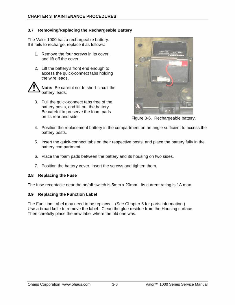
3.7 Removing/Replacing the Rechargeable Battery
The Valor 1000 has a rechargeable battery. If it fails to recharge, replace it as follows:
1. Remove the four screws in its cover, and lift off the cover.
2. Lift the battery’s front end enough to access the quick-connect tabs holding the wire leads.
Note: Be careful not to short-circuit the battery leads.
3. Pull the quick-connect tabs free of the battery posts, and lift out the battery. Be careful to preserve the foam pads on its rear and side. Figure 3-6. Rechargeable battery.
4. Position the replacement battery in the compartment on an angle sufficient to access the battery posts.
5. Insert the quick-connect tabs on their respective posts, and place the battery fully in the battery compartment.
6. Place the foam pads between the battery and its housing on two sides.
7. Position the battery cover, insert the screws and tighten them.
3.8 Replacing the Fuse
The fuse receptacle near the on/off switch is 5mm x 20mm. Its current rating is 1A max.
3.9 Replacing the Function Label
The Function Label may need to be replaced. (See Chapter 5 for parts information.) Use a broad knife to remove the label. Clean the glue residue from the Housing surface. Then carefully place the new label where the old one was.
Ohaus Corporation www.ohaus.com 3-6 Valor™ 1000 Series Service Manual

CHAPTER 4 TESTING
4.1 TESTING
Before and after servicing a Valor 1000 scale, an operational test and various performance tests should be made to confirm that the scale meets specifications. Turn the scale on and allow it to warm up for at least one hour before performing these tests.
NOTE: Make sure the test area is free from drafts and that the scale rests on a level and vibration-free surface.
4.1.1 TEST MASSES REQUIRED
The masses required to test the Ohaus Valor 1000 scales must meet the requirements of ASTM Class 4 or OIML F2 Tolerance. The mass values are listed in Table 4-1.
TABLE 4-1. TEST MASS VALUES
Model Weight (g)
V11P3 500, 1000, 2000, 3000
V11P6 1500, 3000, 4500, 6000
V11P15 3000, 4000, 9000, 11000, 15000
V11P30 6000, 8000, 15000, 22000, 30000 4.2 Operational Test
1. Connect a functioning Power Adapter to the scale power receptacle located on the bottom of the scale.
2. Plug the Power Cord into a suitable power source, or power the scale on using battery power. (Assure that the battery is charged beforehand.)
4.3 Segment Display Test
Turn the scale on, and ensure that all segments are enabled and displayed briefly. The scale’s model number appears next, followed by a software revision number. This is a Segment Display Test. (See Figure 4-1.)
Figure 4-1. Segment Display
Valor™ 1000 Series Service Manual 4-1 Ohaus Corporation www.ohaus.com

CHAPTER 4 TESTING
4.4 Performance Tests
Accurate performance of the Valor 1000 scales is determined by a series of four performance tests. The displayed readings are compared with the tolerances listed for each test in Table 1-2. Tolerance values are expressed in counts. A one-count difference is shown in the last digit on the scale display.
NOTE: The following performance tests are used to evaluate scale operation before and after repairs. The scale must meet the requirements specified in each test as well as the other specifications listed in Table 1-1. Before proceeding with the following tests, the scale should be calibrated. (See Appendix A and B.)
4.4.1 Precision Test
The Precision Test measures the Standard Deviation of a set of similar weight readings, which should match the specification for each model, listed in Table 1-1.
1. Power on the balance. The reading on the display should be 0g.
2. Select a mass weighing near the maximum capacity of the balance, and place it on the center of the Pan. Observe and record the reading.
3. Remove the mass. The reading should return to 0g ±1 count.
4. Repeat this test three times. The reading should be within ±1 count of the reading recorded. If so, the balance passes the Precision Test.
5. If the deviation for any set of readings (using the same mass placed on the center of the Pan) is greater than ±1 d, the balance does not meet the precision specification. Inspect and correct the following areas:
– Check for mechanical obstructions. Any foreign object touching any part of the moving assemblies will cause a balance to fail the Precision Test. Inspect and correct as necessary.
– If the scale does not meet specifications, move it to a suitable location, ensure that it is level, and try again. If it still does not meet specifications, perform a service calibration, and try again. (See Appendix B for Service Calibration.)
Ohaus Corporation www.ohaus.com 4-2 Valor™ 1000 Series Service Manual

CHAPTER 4 TESTING
4.4.2 Repeatability Test
Repeatability is the Standard Deviation of a set of similar weight readings.
Requirements: – To perform this test a single mass must be used for all readings.
– The test mass should be approximately ½ of the capacity of the instrument.
– Wear gloves when handling the mass.
Before starting a repeatability test, set up the instrument as follows:
Set Up: Follow the steps in Appendix A, Section A-2, Setup and Calibration.
Record Settings: Zero Tracking Setting = ____________
Displayed Units = ____________
Mass Used = ____________
TEST PROCEDURE: 1. Zero the instrument, if it does not read zero.
2. Using a test mass approximately half the capacity of the instrument, place the mass on the center of platform. Record the reading on the worksheet provided.
3. Remove the mass from the platform.
4. Repeat this test starting at Step 1 until you record a total of ten readings
Fill in the worksheet (Table 4-2) with the ten (10) readings.
Valor™ 1000 Series Service Manual 4-3 Ohaus Corporation www.ohaus.com

CHAPTER 4 TESTING
4.4.2 Repeatability Test
TABLE 4-2. REPEATABILITY WORKSHEET
n Reading Delta = Reading – Mean Delta x Delta
1
2
3
4
5
6
7
8
9
10 n = number of Reading Mean = Sum of readings / 10 Delta = Reading – Mean
Standard Deviation = Square Root of (sum of (Delta x Delta) / 9)
5. Add the ten readings and divide the total by 10 to find the Mean (average).
6. Mean = (Reading 1 + Reading 2 + Reading 3 + Reading 4 + Reading 5
7. + Reading 6 + Reading 7+ Reading 8 + Reading 9 + Reading 10) / 10 Mean =________
6. Calculate the Delta for each reading and record in the work sheet. Delta = Reading – Mean
7. Calculate the Delta x Delta for each reading and record in worksheet.
8. Add the ten Delta x Delta values and divide by 9
9. Calculate the Standard Deviation by applying the square root of the result from step 8. Standard Deviation =___________
Note: If the balance does not meet specifications, move it to a suitable location, ensure that it is level, and try again.
Ohaus Corporation www.ohaus.com 4-4 Valor™ 1000 Series Service Manual

CHAPTER 4 TESTING
4.6.3 Linearity Test
This test is used to determine the linearity of the unit throughout its operating range. The masses used to perform this test can be utility masses
NOTE: The scale must pass the Precision and Repeatability Tests, and be calibrated before the Linearity Test may be performed.
TABLE 4-3. LINEARITY TEST MASSES Capacity (g) 3000 x .5g 6000 x 1g 15000 x 2g 30000 x 10g
Reference Wt. 1000 1500 4000 8000
Load 1 500 1500 3000 6000 Load 2 1500 3000 9000 15000 Load 3 2000 4500 11000 22000
NOTE:
All masses are nominal values. Use the same reference mass throughout the procedure.
1. Place the test mass on the Scale, record the weight and remove.
2. Place Load 1 on the Scale and press ON/ >O/T<.
3. Place the test mass on the Scale, record the weight and remove.
4. Place Load 2 on the Scale and press ON/ >O/T<.
5. Place the test mass on the Scale, record the weight and remove.
6. Place Load 3 on the Scale and press ON/ >O/T<.
7. Place the test mass on the Scale and record the weight.
8. The difference in the weights of the test mass should be within ±2 d, as specified in the Tables 1-1 and 1-2. If not, calibrate (see Appendix A.1) and repeat the test.
9. If the Scale remains out of tolerance, the Load Cell may need to be replaced.
4.4.4 Off-Center Load Test The Off-Center Load Test is used to determine whether displayed weight values are affected by moving the sample to different areas of the Pan.
1. Place half of the scale’s capacity in the center of the Pan.
2. Note the reading.
3. Move the mass halfway (between the center and the edge) to the front of the Pan. Note any differences in the displayed weight reading.
4. Repeat the test for the back, left, and right position of the Pan.
5. Maximum allowable change in displayed weight readings for each of the four positions can be found in Tables 1-1 and 1-2 (Specifications, page 1-2 and 1-3). If this maximum is exceeded, follow procedures in Section 4.4.5, Adjusting Off Center Load.
Valor™ 1000 Series Service Manual 4-5 Ohaus Corporation www.ohaus.com

CHAPTER 4 TESTING
4.4.5 Adjusting Off Center Load
If the Off Center Load (OCL) is excessive, perform adjustment as follows:
Top view of Load Cell
Side view of Load Cell
2 3 Weighing Pan’s center, with points A – D indicated
1 4
Figure 4-2. Scale drawing of Valor 1000 Load Cell and Weighing Pan.
1. Place the test weight in the center of the Weighing Pan.
2. Tare the balance.
3. Move the weight to point A and record the reading.
4. Move the weight to point B and record the reading.
5. Move the weight to point C and record the reading.
6. Move the weight to point D and record the reading.
7. If the reading at point A is negative, file at points 1 and 4 AT AN ANGLE.
8. If the reading at point B is negative, file at points 1 and 2 STRAIGHT ACROSS.
9. If the reading at point C is negative, file at points 2 and 3 AT AN ANGLE.
10. If the reading at point D is negative, file at points 3 and 4 STRAIGHT ACROSS.
Note: It is not recommended that you try to adjust more than –5 counts if the beam has been filed already. If the beam has not been filed previously, you can adjust –10 counts. Remember, when filing you are weakening the beam. File a little at a time.
Ohaus Corporation www.ohaus.com 4-6 Valor™ 1000 Series Service Manual

CHAPTER 5 PARTS LISTS & DIAGRAMS
This section of the manual contains exploded views of the Valor 1000 scales. The exploded view drawings are designed to identify the parts which can be serviced on the scale in the field.
NOTE: In all cases where a part is replaced, the scale must be thoroughly checked after the replacement is made. The scale MUST meet the parameters of all applicable specifications in this manual.
If further technical information is needed, please contact your local Ohaus distributor, or: Ohaus Corporation, www.ohaus.com 19A Chapin Road P.O. Box 2033 Pine Brook, NJ 07058-2033 USA Tel: 973-377-9000 Fax: 973-593-0359 In the United States call toll free, 800-526-0659 between 8:00 a.m. and 6:00 p.m. EST.
Valor™ 1000 Series Service Manual 5-1 Ohaus Corporation www.ohaus.com

CHAPTER 5 PARTS LISTS & DIAGRAMS
5.1 VALOR 1000 SCALES: HOUSING & INTERNAL PARTS
11
80
17
10
9
8
6
3
21
20
4
5
7
16
14
20
20
20
20
Figure 5-1. Valor 1000 Scales: Housing & Internal Parts.
Ohaus Corporation www.ohaus.com 5-2 Valor™ 1000 Series Service Manual

CHAPTER 5 PARTS LISTS & DIAGRAMS
5.1 VALOR 1000 SCALES: HOUSING & INTERNAL PARTS
TABLE 5-1. VALOR 1000 SCALES: HOUSING & INTERNAL PARTS
Drawing Item Description
1 Pan
2 Pan Support
3 Function Label
4 Top Housing
5 Back Overlay
6 PCB set: Main and Switches
7 Frame
8 Load Cell
9 Level Bubble
10 Bottom Housing
11 Wiring Harnesses & On/Off Switch
14 Adjustable Feet, Set of 4
16 Rechargeable Battery
17 Battery Cover
20 Hardware Kit
80 Adapter
Note: For parts numbers, see your local Ohaus distributor, or visit www.ohaus.com.
Valor™ 1000 Series Service Manual 5-3 Ohaus Corporation www.ohaus.com

CHAPTER 5 PARTS LISTS & DIAGRAMS
Ohaus Corporation www.ohaus.com 5-4 Valor™ 1000 Series Service Manual

APPENDIX A STANDARD CALIBRATION
APPENDIX A. STANDARD CALIBRATION
A.1 CALIBRATION Standard calibration should be performed prior to using a scale, and after service. A 3kg mass is required to perform span calibration on all models.
NOTE: Be careful not to touch the scale or the table while calibration is in progress, as it will cause the process to fail.
Preliminary Steps:
1. Be sure the scale is level and stable during the entire calibration process.
2. Allow the scale to warm up for approximately five minutes after stabilizing to room temperature.
3. To abort calibration, turn the scale off anytime during the calibration process.
NOTE: There is a Menu Lock jumper on the PCB. It must be in the “on” position to calibrate:
Menu Lock Jumper
Figure A-1. Main PCB’s Menu Lock Jumper must be ON to calibrate.
1. Turn on the scale. When display flashes all segments (888888) press and hold ZERO and SELECT at the same time. SET--- appears at the end of power on sequence.
SET---
2. Press SELECT until SET-F1 appears. Then press ZERO until the display shows Load 0. Make sure pan is empty, then press ZERO to start calibration. CAL 0 appears, then Load F.
Load 0
3. Press ZERO to display F 3.000. Note: Calibration weight is 3 kg (3000 g) for all models: DO NOT CHANGE. Put the displayed weight on the scale, and press ZERO to accept. After completion, scale will be in weighing mode.
F 3.000
Valor™ 1000 Series Service Manual A-1 Ohaus Corporation www.ohaus.com

APPENDIX A STANDARD CALIBRATION
A.2 SETUP AND CALIBRATION
TABLE A-1. INITIAL CONFIGURATION SETTINGS FOR EACH MODEL
MODEL Division (A----x)
Decimal point(b----x)
Capacity (c-----x)
Zero tracking (d----x)
Calibration Weight
V11P3 0.5g: x=5 Kg: x=4 or g: x=1
3.0000kg or 3000.0g x=3 3.000
V11P6 1g: x=1 Kg:x=3 or g: x=0
6.000kg or 6000g x=3 3.000
V11P15 2g: x=2 Kg: x=3 or g: x=0
15.000kg or 15000g x=3 3.000
V11P30 5g: x=5 Kg: x=3 or g: x=0
30.000kg or 30000g x=3 3.000
Follow these steps for initial Setup and Calibration:
1. Turn on the scale. When display flashes all segments (888888) press and hold ZERO and SELECT at the same time. SET--- appears at the end of power on sequence.
SET---
2. Press SELECT until SET-F1 appears. SET-F1 3. Press ZERO to display A____x (x=divisions in grams: 1,2,5,10,20,50).
Press ZERO to accept the setting shown, or press M+ or TARE to increment or decrement setting to match value for specific model – see Table A-1.)
Note: Settings for each model must match Table A-1.
A___2
4. Press ZERO to display b____x (x=decimal point: 0,1,2,3). Press ZERO to accept the setting shown, or press M+ or TARE to move up or down to match value for specific model – see Table A-1.
B___3
5. Press ZERO to display Cxxxxx (xxxxx= capacity of scale). Press ZERO to accept the setting shown, or press M+ or TARE to move up or down to match value for specific model – see Table A-1. (Press SELECT to move to the next digit.)
C 15.000
6. Press ZERO to display dx (x=Zero tracking setting: 0-9 from 0.125d to 1.25d). Press ZERO to accept the setting shown, or M+ or TARE to move up or down to match value for specific model – see Table A-1. Setup is now complete. Calibration follows immediately:
D 3
7. Press ZERO and display will show Load 0. Make sure pan is empty, then press ZERO to accept. CAL 0 appears, then Load F. Load 0
8. Press ZERO to display Fxxxxx (xxxxx=Span weight ). Note: Span weight is 3000 g (3 kg) for all models: DO NOT CHANGE. Put displayed weight on the scale, and press ZERO to accept. After completion, scale will be in weighing mode.
F 3.000
Ohaus Corporation www.ohaus.com A-2 Valor™ 1000 Series Service Manual


*80252599* P/N 80252599 SERVICE MANUAL: Valor 1000 SERIES SCALES