service & parts manual electric fryers pro...
TRANSCRIPT

Frymaster, a member of the Commercial Food Equipment Service Association, recommends using CFESA Certified Technicians.
24-Hour Service Hotline 1-800-551-8633 03/2016
*8195990*
P
RO
SE
RIE
S
EL
EC
TR
IC F
RY
ER
S
Service &
Parts M
anu
al

i
NOTICE IF, DURING THE WARRANTY PERIOD, THE CUSTOMER USES A PART FOR THIS ENODIS
EQUIPMENT OTHER THAN AN UNMODIFIED NEW OR RECYCLED PART PURCHASED DIRECTLY FROM FRYMASTER DEAN, OR ANY OF ITS AUTHORIZED SERVICE CENTERS, AND/OR THE
PART BEING USED IS MODIFIED FROM ITS ORIGINAL CONFIGURATION, THIS WARRANTY WILL BE VOID. FURTHER, FRYMASTER DEAN AND ITS AFFILIATES WILL NOT BE LIABLE FOR ANY
CLAIMS, DAMAGES OR EXPENSES INCURRED BY THE CUSTOMER WHICH ARISE DIRECTLY OR INDIRECTLY, IN WHOLE OR IN PART, DUE TO THE INSTALLATION OF ANY MODIFIED PART
AND/OR PART RECEIVED FROM AN UNAUTHORIZED SERVICE CENTER.
DANGER Copper wire suitable for at least 167°F (75°C) must be used for power connections.
DANGER The electrical power supply for this appliance must be the same as indicated on the
rating and serial number plate located on the inside of the fryer door.
DANGER This appliance must be connected to the voltage and phase as specified on the rating
and serial number plate located on the inside of the fryer door.
DANGER All wiring connections for this appliance must be made in accordance with the wiring diagrams furnished with the equipment. Wiring diagrams are located on the inside of
the fryer door.
DANGER Do not store or use gasoline or other flammable vapors and liquids in the vicinity of this
or any other appliance.
WARNING Do not attach accessories to this fryer unless fryer is secured from tipping. Personal
injury may result.
WARNING Frymaster fryers equipped with legs are for permanent installations. Fryers fitted with legs must be lifted during movement to avoid damage and possible bodily injury. For a moveable or portable installation, Frymaster optional equipment casters must be used.
Questions? Call 1-800-551-8633
WARNING Do not use water jets to clean this equipment.
DANGER All wiring connections for this appliance must be made in accordance with the wiring diagrams furnished with the equipment. Wiring diagrams are located on the inside of
the fryer door.
WARNING This equipment is intended for indoor use only. Do not install or operate this
equipment in outdoor areas.

ii
ELECTRICAL POWER SPECIFICATIONS
kW VOLTAGE PHASE WIRE
SERVICE
MINIMUM SIZE AMPS PER LEG
AWG mm2 L1 L2 L3 14 208 3 3 6 16 39 39 39 14 �� � ϖ3 3 3 6 16 34 34 34 14 480 3 3 8 10 17 17 17 14 220/380 3 4 6 16 21 21 21 14 240/415 3 4 6 16 20 20 21 14 230/400 3 4 6 16 21 21 21
ALL EPRI 14kW
(SOLID STATE)
208 3 3 6 16 39 39 39 240 3 3 6 16 34 34 34
220/380 3 4 6 16 21 21 21 240/415 3 4 6 16 20 20 20
17 208 3 3 6 16 48 48 48 17 240 3 3 6 16 41 41 41 17 480 3 3 6 16 21 21 21 17 220/380 3 4 6 16 26 26 26 17 240/415 3 4 6 16 24 24 24 17 230/400 3 4 6 16 25 25 25
ALL EPRI 17kW
(SOLID STATE)
208 3 3 6 16 48 48 48 240 3 3 6 16 41 41 41
220/380 3 4 6 16 26 26 26 240/415 3 4 6 16 24 24 24
22 208 3 3 4 25 61 61 61 22 240 3 3 4 25 53 53 53 22 480 3 3 6 16 27 27 27 22 220/380 3 4 6 16 34 34 34 22 240/415 3 4 6 16 31 31 31 22 230/400 3 4 6 16 32 32 32
TABLE OF CONTENTSPage
CAUTIONARY STATEMENTS iELECTRICAL POWER SPECIFICATIONS iiCHAPTER 1 – SERVICE PROCEDURES 1-1
1.1 General 1-11.2 Replacing a Controller 1-11.3 Replacing Component Box Components 1-21.4 Replacing a Temperature Probe or High-Limit Thermostat 1-31.5 Replacing a Heating Element 1-51.6 Replacing Contactor Box Components 1-61.7 Replacing a Frypot 1-71.8 Built-in Filtration System Service Procedures 1-81.9 Basket Lift Service Procedures 1-121.10 Interface Board Diagnostic Charts 1-151.11 Wiring Diagrams 1-16
CHAPTER 2 – PARTS LIST 2-12.1 Accessories 2-12.2 Basket Lift Assembly and Associated Parts 2-22.3 Cabinetry 2-42.4 Drain System Components 2-82.5 Electronics and Wiring Components 2-162.6 Filtration System Components 2-282.7 Frypot Assemblies and Associated Parts 2-312.8 Oil Return System Components 2-33
1-1
PRO SERIES ELECTRIC FRYERSCHAPTER 1: SERVICE PROCEDURES
1.1 General
Before performing any maintenance on your Frymaster fryer, disconnect the fryer from the electricalpower supply.
When electrical wires are disconnected, it is recommended that they be marked in such a way as tofacilitate re-assembly.
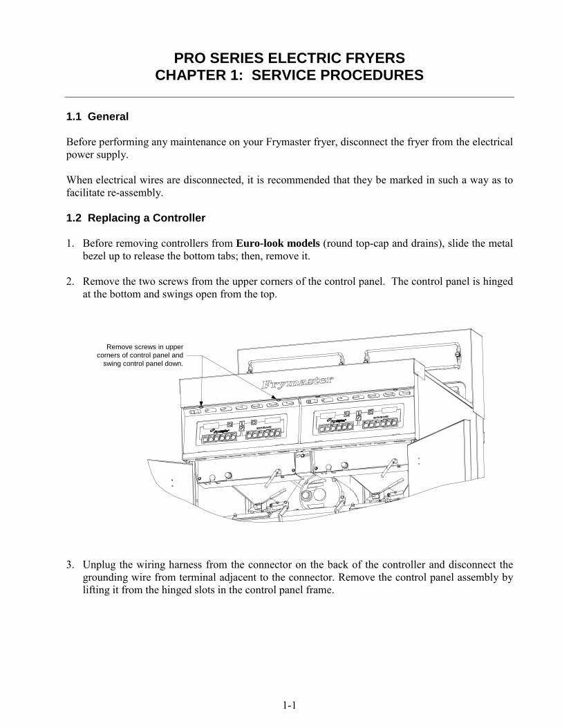
1.2 Replacing a Controller
1. Before removing controllers from Euro-look models (round top-cap and drains), slide the metalbezel up to release the bottom tabs; then, remove it.
2. Remove the two screws from the upper corners of the control panel. The control panel is hingedat the bottom and swings open from the top.
Remove screws in uppercorners of control panel and
swing control panel down.
3. Unplug the wiring harness from the connector on the back of the controller and disconnect thegrounding wire from terminal adjacent to the connector. Remove the control panel assembly bylifting it from the hinged slots in the control panel frame.

1-2
4. Remove the controller from the control panel assembly and install the replacement controller.Reinstall the control panel assembly by reversing steps 1 and 2.
1.3 Replacing Component Box Components
1. Remove the two screws from the upper corners of the control panel and allow the control panelto swing down (see steps 1 and 2 of section 1.2 on preceding page).
2. Unplug the wiring harness from the 15-pin connector on the interface board and disconnect thegrounding wire from terminal adjacent to the 15-pin connector on the back of the controller.Remove the control panel assembly by lifting it from the hinge slots in the control panel frame.
3. Disconnect the wiring from the component to be replaced, being sure to make a note of whereeach wire was connected.
NOTE: If replacing the interface board, connectors J1 and J2 must also be disconnected fromthe 12-pin connectors on the rear of the component box, directly behind the interface board.
4. Dismount the component to be replaced and install the new component, being sure that anyrequired spacers, insulation, washers, etc. are in place.
NOTE: If more room to work is required, the control panel frame and top cap assembly may beremoved by removing the hex head screws that secure it to the fryer cabinet (see illustrationbelow). If this option is chosen, all control panel assemblies must be removed per steps 1 and 2above. The cover plate on the lower front of the component box may also be removed if desired.Removing the component box itself from the fryer is not recommended due to the difficultyinvolved in disconnecting and reconnecting the oil-return valve rods, which pass throughopenings in the component box.
Ground Wire Terminal15-Pin Connector

1-3
Remove these threescrews at each end.
Remove these two screwsfrom the center supports.
Removing the Control Panel Frame and Top Cap Assembly
5. Reconnect the wiring disconnected in step 3, referring to your notes and the wiring diagrams onthe fryer door to ensure that the connections are properly made. Also, verify that no other wiringwas disconnected accidentally during the replacement process.
6. Reverse steps 1 and 2 to complete the replacement and return the fryer to service.
1.4 Replacing a Temperature Probe or High-Limit Thermostat
1. Remove the filter pan and lid from the unit. Drain the frypots into a Shortening Disposal Unit(SDU) or other appropriate metal container.
DANGERDO NOT drain more than one full frypot or two split frypots into the SDU at one time.
2. Disconnect the fryer from the electrical power supply and reposition it to gain access to the rearof the fryer.
3. Remove the tilt housing and back panels from the fryer. The tilt housing must be removed first inorder to remove the upper back panel. To remove the tilt housing, raise the elements and allowthem to rest on the basket support racks as shown in the photo below.

1-4
Next, remove the hex head screws from the rear edge of the housing. The housing can then belifted straight up and off the fryer. Lift up on the upper back panel to disengage the tabs on itsupper corners from the cutouts in the fryer frame.
4. Disconnect the wire harness at connector C6 and, using a pin pusher, disconnect the probe leadsor high-limit leads from the connector.
5. If replacing a temperature probe, remove the screw securing the probe bracket to the elementand slide the bracket off the element and probe. Pull the probe out of the tilt housing assembly,install the replacement probe, and reattach the element bracket. Secure the upper portion of theprobe with a replacement metal wire tie.
Probe Bracket
Probe Leads
Metal Wire Tie
If replacing a high-limit thermostat, unscrew the thermostat to be replaced. Apply Loctite™ PST567 or equivalent sealant to the threads of the replacement and screw it securely into the frypot.
6. If a temperature probe was replaced, insert the probe leads into the connector (see leftillustration below). For full-vat units or the left half (as viewed from the rear of the fryer) of adual-vat unit, the red lead goes into position 6 and the white into position 7. For the right half ofa dual-vat unit (as viewed from the rear of the fryer), the red lead goes into position 12 and thewhite into position 13.
Rib marks Position 1
6
7
12
13
Probe Lead Positions High-Limit Lead Positions
11
10 4
5
If a high-limit thermostat was replaced, insert the leads into the connector (see right illustrationabove). For full-vat units or the left half of a dual-vat unit (as viewed from the rear of the fryer),the leads go into positions 4 and 5 of the connector. For the right half of a dual-vat unit (asviewed from the rear of the fryer), the leads go into positions 10 and 11. In either case, polaritydoes not matter.
7. Reinstall the back panels and tilt housing to complete the installation, then reverse steps 1 and 2to return the fryer to service.

1-5
1.5 Replacing a Heating Element
1. Perform steps 1-3 of section 1.4, Replacing a Temperature Probe.
2. On dual-vat fryers, and on full-vat fryers where the temperature probe is attached to the elementbeing replaced, disconnect the wire harness containing the probe wiring (connector C6). Using apin pusher, disconnect the probe wires from the connector.
3. On the front of the contactor box, disconnect the 6-pin connector for the left element (as viewedfrom the front of the fryer) or the 9-pin connector for the right element and pull the harness outthrough the rear of the fryer. Press in on the tabs on each side of the connector while pullingoutward on the free end to extend the connector and release the element leads (see photo below).Pull the leads out of the connector and out of the plastic wire loom.
4. Raise the element to the full up position and disconnect the element springs.
5. Remove the nuts and machine screws that secure the element to the tilt plate assembly and pullthe element out of the frypot. NOTE: Full-vat elements consist of two dual-vat elementsclamped together. For full-vat units, remove the element clamps before removing the nuts andmachine screws that secure the element to the tilt plate assembly.
6. If applicable, recover the probe bracket and probe from the element being replaced and installthem on the replacement element, then install the replacement element in the frypot, securing itwith the nuts and screws removed in Step 5.
7. Route the element leads through the wire loom to prevent chafing and press the pins into theconnector in accordance with the diagram below, then close the connector to lock the leads inplace. NOTE: It is critical that the wires be routed through the loom to prevent chafing.
1
4
2
5
3
6
1
4
2
5
3
6
789
5R 4R6R 1R2R3R
Pip marks Position 1
5L 4L6L 1L2L3L

1-6
Remove these screws to dismount the left contactor box.The right contactor box is secured in a similar manner.
8. Insert the element connector into the receptacle on the front of the contactor box, ensuring thatthe latches lock.
9. If disconnected in step 2, insert the temperature probe leads into the wiring harness connector(see illustration below). For full-vat units or the right half of a dual-vat unit, the red lead goesinto position 6 and the white into position 7. For the left half of a dual-vat unit, the red lead goesinto position 12 and the white into position 13. NOTE: Right and left refer to the fryer asviewed from the rear.
Rib marks Position 1
6
7
12
13
10. If disconnected in step 2, reconnect connector C6 of the wiring harness.
11. Reconnect the element springs and lower the element back down onto the basket rack.
12. Reinstall the tilt housing and back panels, reposition the fryer under the exhaust hood, andreconnect it to the electrical power supply.
1.6 Replacing Contactor Box Components
1. If replacing a contactor box above the built-in filter system, remove the filter pan and lid fromthe unit. Drain the frypots into a Shortening Disposal Unit (SDU) or other appropriate metalcontainer. If replacing a contactor box in a non-filter unit, drain the frypot above the box into aShortening Disposal Unit (SDU) or other appropriate metal container.
DANGERDO NOT drain more than one full frypot or two split frypots into the SDU at one time.
2. Disconnect the fryer from the electrical power supply.
3. Unplug the wiring harnesses from the contactor box to be serviced.
4. Remove the two screws that secure the box in place. NOTE: If you remove the screws fromboth boxes at the same time, the boxes will jam against each other and neither can be removed.

1-7
5. Carefully lower the box to the floor and pull it out the front of the fryer. Remove the top coverto access contactors and other components.
6. After performing necessary service, reverse steps 1-5 to return the fryer to operation.
1.7 Replacing a Frypot
1. Drain the frypot into the filter pan or, if replacing a frypot over the filter system, into aShortening Disposal Unit (SDU) or other appropriate metal container. If replacing a frypot overthe filter system, remove the filter pan and lid from the unit.
DANGERDO NOT drain more than one full frypot or two split frypots into the SDU at one time.
2. Disconnect the fryer from the electrical power supply and reposition it to gain access to both thefront and rear.
3. On Euro-look models, slide the metal bezel up to release the bottom tabs; then, remove it.
4. On all models, remove the two screws from the upper corners of the control panels and allowthem to swing down (see illustration and photo on page 1-1).
5. Unplug the wiring harnesses and ground wires from the backs of the controllers. Remove thecontrollers by lifting them from the hinge slots in the control panel frame.
6. Remove the tilt housing and back panels from the fryer. The tilt housing must be removed first inorder to remove the upper back panel. To remove the tilt housing, raise the elements and allowthem to rest on the basket support racks (see photo on page 1-3).
Next, remove the hex head screws from the rear edge of the housing. The housing can then belifted straight up and off the fryer. Lift up on the upper back panel to disengage the tabs on itsupper corners from the cutouts in the fryer frame.
7. Dismount the top cap by removing the hex head screws at each end that secure it to the controlpanel frame.
8. Remove the hex head screw that secures the front of the frypot to the cabinet cross brace.
9. Remove the top-connecting strip that covers the joint with the adjacent frypot.
10. On standard models, unscrew the Teflon vent/vacuum-breaker tube fitting, open the drain tubecleanout covers, unscrew the retainer nuts from the drain valve nipples, and remove the tubeassembly from the fryer.
On Euro-look models, unscrew the Teflon vent/vacuum-breaker tube fitting, unscrew the nutlocated on the front of each section of drain tube, and remove the tube assembly from the fryer.
11. Remove the covers from the drain safety switch(es) and disconnect the switch wiring at theswitch(es).

1-8
12. At the rear of the fryer, unplug the C6 connector and, using a pin pusher, disconnect the high-limit thermostat leads.
13. Disconnect the oil return flexline(s) at the frypot end(s).
14. Raise the elements to the “up” position and disconnect the element springs.
15. Remove the machine screws and nuts that secure the tilt plate and element assembly to thefrypot. Carefully lift the tilt plate and element assembly from the frypot and secure it to the crossbrace on the rear of the fryer with wire ties or tape.
16. Carefully lift the frypot from the fryer and place it upside down on a stable work surface.
17. Recover the drain valve(s), oil return flexline connection fitting(s), and high-limit thermostat(s)from the frypot. Apply Loctite™ PST 567 or equivalent sealant to the threads of the recoveredparts and install them in the replacement frypot.
18. Carefully lower the replacement frypot into the fryer. Reinstall the hex head screw removed instep 7 to attach the frypot to the fryer.
19. Position the tilt housing and element assembly in the frypot and reinstall the machine screws andnuts removed in step 14.
20. Reconnect the oil return flexlines to the frypot, and replace aluminum tape, if necessary, tosecure heater strips to the flexlines.
21. Insert the high-limit thermostat leads disconnected in step 11 (see illustration on page 1-4 for pinpositions).
22. Reconnect the drain safety switch wiring to the switch(es) in accordance with the diagram belowthen reinstall the switch covers.
58C BLK
57C RED
RIGHTDRAIN SAFETY SWITCH
LEFTDRAIN SAFETY SWITCH
(DUAL-VAT ONLY)55C BLK
56C RED
23. Reinstall the drain tube assembly.
24. Reinstall the tilt housing and back panels, top cap, and top connecting strip.
25. Reinstall controllers in the control panel frame and reconnect the wiring harnesses and groundwires.
26. Reposition the fryer under the exhaust hood and reconnect it to the electrical power supply.

1-9
1.8 Built-in Filtration System Service Procedures
1.8.1 Filtration System Problem Resolution
One of the most common causes of filtration problems is placing the filter paper on the bottom of thefilter pan rather than over the filter screen.
CAUTIONEnsure that filter screen is in place prior to filter paper placement and filter pumpoperation. Improper screen placement is the primary cause of filtration system
malfunction.
When the complaint is “the pump is running, but no oil is being filtered,” check the installation ofthe filter paper and ensure that the correct size is being used.
If the pump motor overheats, the thermal overload will trip and the motor will not start until it isreset. If the pump motor does not start, press the red reset switch (button) located on the rear of themotor at the front of the fryer.
If the pump starts after resetting the thermal overload switch, then something is causing the motor tooverheat. A major cause of overheating is when several frypots are filtered sequentially, thusoverheating the pump and motor. Allow the pump motor to cool at least 30 minutes before resumingoperation. Pump overheating can be causedby:
• Solidified shortening in the pan orfilter lines, or
• Attempting to filter unheated oil(cold oil is more viscous,overloading the pump motor andcausing it to overheat).
If the motor runs but the pump does not,there is a blockage in the pump. Incorrectlysized or installed paper/pads will allow foodparticles and sediment to pass through thefilter pan and into the pump. Whensediment enters the pump, the gears bind,causing the motor to overload, againtripping the thermal overload. Shorteningthat has solidified in the pump will alsocause it to seize, with the same result.
A pump seized by debris or hard shorteningcan usually be freed by manually movingthe gears with a screwdriver or otherinstrument.
Sediment Particle
Oil Flow
Up for reverse
Down for forward
Sediment Particle

1-10
Disconnect power to the filter system, remove the input plumbing from the pump, and use ascrewdriver to manually turn the gears.
● Turning the pump gears in reverse will release a hard particle.
● Turning the pump gears forward will push softer objects and solid shortening through thepump and allow free movement of the gears.
Incorrectly sized or installed paper/pads will also allow food particles and sediment to pass throughand clog the suction tube on the bottom of the filter pan. Particles large enough to block the suctiontube may indicate that the crumb tray is not being used. Pan blockage can also occur if shortening isleft in the pan and allowed to solidify. Blockage removal can be accomplished by forcing the itemout with an auger or drain snake. Compressed air or other pressurized gases should not be used toforce out the blockage.
1.8.2 Replacing the Filter Motor, Filter Pump, and Related Components
1. Remove the filter pan and lid from the unit. Drain the frypots into a Shortening Disposal Unit(SDU) or other appropriate metal container.
DANGERDO NOT drain more than one full frypot or two split frypots into the SDU at one time.
2. Disconnect the fryer from the electrical power supply and reposition it to gain access to both thefront and rear.
3. Remove the two lower back panels, unplug the wiring harnesses from the contactor boxes, andremove the two screws that secure one of the boxes in place (it doesn’t matter which one; seeillustration on page 1-6). NOTE: If you remove the screws from both boxes at the same time,the boxes will jam against each other and neither can be removed.
4. Carefully lower the box to the floor and pull it out the front of the fryer. Remove the remainingbox following the same procedure.
5. Disconnect the two flexlines running to the oil-return manifold at the rear of the fryer. Removethe nut and bolt that secures the bridge to the oil-return manifold.
Disconnect PumpSolenoid flexline here.
Disconnect Vacuum-BreakerSolenoid flexline here.

1-11
6. Disconnect the pump suction flexline at the end of the filter pan connection.
Disconnect PumpSuction flexline here.
7. Remove the cover plate from the front of the motor and disconnect the motor wires.
8. Unplug the 15-pin connector from the rear of the left component box and, using a pin pusher,disconnect the solenoid valve wires (pins 4, 6, 10 and 12). NOTE: If the vacuum-breakersolenoid valve is connected to the manifold rather than the pump, its wires (pins 4 and 6) do notneed to be disconnected.
9. Remove the two nuts and bolts that secure the front of the bridge to the cross brace and carefullyslide the bridge rearward off the cross brace until its front end can be lowered to the floor. Becareful not to let the rear of the bridge slip off the manifold at this point. NOTE: In some earlyproduction units, the bridge will not slide far enough to the rear to clear the front brace. In suchcases, the front brace must be removed. It is held in place by two hex head screws on each endand a nut and bolt inside the brace near each end.
10. Get a good grip on the bridge, carefully pull it forward off the oil-return manifold, and lower theentire assembly to the floor. Once on the floor, pull the assembly out the front of the fryer.
11. When required service has been completed, reverse steps 6-12 to reinstall the bridge. NOTE:The black motor wires go on the top terminal, the white on the bottom. The pump solenoid valvewires go in positions 10 and 12 of the 15-pin connector; the vacuum-breaker solenoid valvewires go in positions 4 and 6. In both cases, polarity does not matter.
12. Once the bridge is back in place, reverse steps 4 and 5 to reinstall the contactor boxes.
13. Reconnect the unit to the electrical power supply, and verify that the pump is functioningcorrectly (i.e., when a filter handle is placed in the ON position, the motor should start and thereshould be strong suction at the intake fitting and outflow at the power shower or rear flush port).
14. When proper operation has been verified, reinstall the back panels and the filter pan and lid, andreturn the fryer to service.

1-12
1.8.3 Replacing the Filter Transformer or Filter Relay
Remove the left controller from the fryer to expose the interior of the left component box. The filtertransformer and relay are located as shown in the illustration below. NOTE: The right componentbox is identical to the left except that the filter transformer and relay are not present.
FilterRelay
FilterTransformer
Dual-vat configuration illustrated. In full-vat units, left filter handle is not present.
1.9 Basket Lift Service Procedures
Pro Series electric fryers may be equipped with automatic basket lifts. Basket lifts always come inpairs, although each operates independently.
A modular basket lift (illustrated below) is a self-contained sub-assembly consisting of a pair oftoothed rods which support removable basket lift arms, a pair of reversible-drive gear motors, andfour microswitches. The gear motors engage the teeth of the rods, moving them up or downdepending upon the motors’ direction of rotation. The microswitches at the upper and lower limitsof movement stop the motors when the basket is in the full up or full down position.
Timing circuitry in the controller initiates and stops basket lift operation depending upon thevariables programmed by the operator. When the product button is pressed, the timing circuitryactivates a coil in the basket lift relay to supply power to the lower microswitch. The microswitchesstop the motor at the lift’s upper and lower travel limits and reverse the direction of current flow thusreversing the motor direction.
When the product button is pushed on the computer/controller, current flows through a coil in thebasket lift relay, causing the lower circuit to be activated. The basket lift lowers, closing thenormally open upper-micro-switch. When the downward-moving rod opens the lower normallyclosed microswitch, power to the motor ceases to flow. When the computer/controller times out, thecurrent to the relay coil is cut, allowing the upper circuit to be activated. The basket lift then raisesand re-closes the lower microswitch. When the basket lift rod clears the upper microswitch, themicroswitch reopens, power to the circuit is cut, and the motor stops. Pushing the product buttonrestarts the cycle.

1-13
100-120V Configuration 208-250V Configuration
Problems with the basket lift can be grouped into three categories:
● Binding/jamming problems● Motor and gear problems● Electronic problems
BINDING/JAMMING PROBLEMS
Noisy, jerky or erratic movement of the lifts is usually due to lack of lubrication of the rods and theirbushings. Apply a light coat of Lubriplate® or similar lightweight white grease to the rod andbushings to correct the problem.
With the modular basket lift, another possible cause of binding is improper positioning of the motor,which prevents the gear from correctly engaging the teeth in the rod. To correct the problem, loosenthe screws that hold the motor in place and move it forward or backward until the rod has justenough slack to be rotated slightly.
MOTOR AND GEAR PROBLEMS
With the modular basket lift, the most likely problem to be encountered in this category is erraticmotion of the lift due to a worn drive gear. Failure to keep the lift rod and bushings properlylubricated will cause unnecessary wear of the gear. The problem is corrected by replacing the worngear.
If the lift cycles correctly but fails to remain in the up position (i.e., goes up, but then slowly settlesback down into the frypot), the problem is a failed motor brake. A failed motor brake cannot berepaired and requires replacement of the motor itself.
If power is reaching the motor but the motor fails to run, the motor is burned out and must bereplaced.

1-14
ELECTRONIC PROBLEMS
Within this category are problems associated with the relays, microswitches, capacitors, resistors,interface board, wiring, and controls. The most common problem in this category is a lift thatcontinuously travels up and down. This is usually caused by a microswitch that is out of adjustment.Troubleshooting the electronics of a modular basket lift is simply a process of verifying current flowthrough the individual components up to and including the motor. Using a multimeter set to the 250VAC range, check the connections on both sides of the component for the presence of the appliedline voltage. The schematic below and the wiring diagram on page 1-15 identify the componentsand wiring connection points.

1-15
1.10 Interface Board Diagnostic Chart
The following diagram and charts provide ten quick system checks that can be performed using onlya multimeter.
Meter Setting Test Pin Pin Results12 VAC Power 50 VAC Scale 1 of J2 3 of J2 12-16 VAC24 VAC Power 50 VAC Scale 2 of J2 Chassis 24-30 VAC*Probe Resistance (RH) R X 1000 OHMS 11 of J2 12 of J2 See Chart*Probe Resistance (LH) R X 1000 OHMS 3 of J1 2 of J1 See ChartHi-Limit Continuity (RH) R X 1 OHMS 7 of J2 4 of J2 0 - OHMSHi-Limit Continuity (LH) R X 1 OHMS 4 of J1 7 of J1 0 - OHMSLatch Contactor Coil (RH) R X 1 OHMS 8 of J2 Chassis 3-10 OHMSLatch Contactor Coil (LH) R X 1 OHMS 5 of J1 Chassis 3-10 OHMSHeat Contactor Coil (RH) R X 1 OHMS 9 of J2 Chassis 18-25 OHMSHeat Contactor Coil (LH) R X 1 OHMS 6 of J1 Chassis 18-25 OHMS
* Disconnect 15-Pin harness from the computer/controller before testing the probe circuit.
Diagnostic LED Legend
CMP indicates power from 12V transformer24 indicates power from 24V transformerHI (RH) indicates output (closed) from right latch
relayHI (LH) indicates output (closed) from left latch
relayHT (RH) indicates output from right heat relayHT (LH) indicates output from left heat relayAL (RH) indicates output (open) from right latch
relayAL (LH) indicates output (open) from left latch
relay
123
456
8 79
101112
131415
1
2
3
4
5
6
7
8
9
10
11
12
1
2
3
4
5
6
7
8
9
10
11
12
K1 K2 K3 K4
Left LatchRelay
Right LatchRelay
LeftHeatRelay
RightHeatRelay
Test PointsJ1 Left J2 Right
Diagostic LEDs
M
H N
Normally Closed Lower-limitMicroswitch
6
To computer/controller viainterface board
Basket LiftRelay3
1 or 4
5
Normally Open Upper-limitMicroswitch
Modular Basket Lift Schematic

1-16
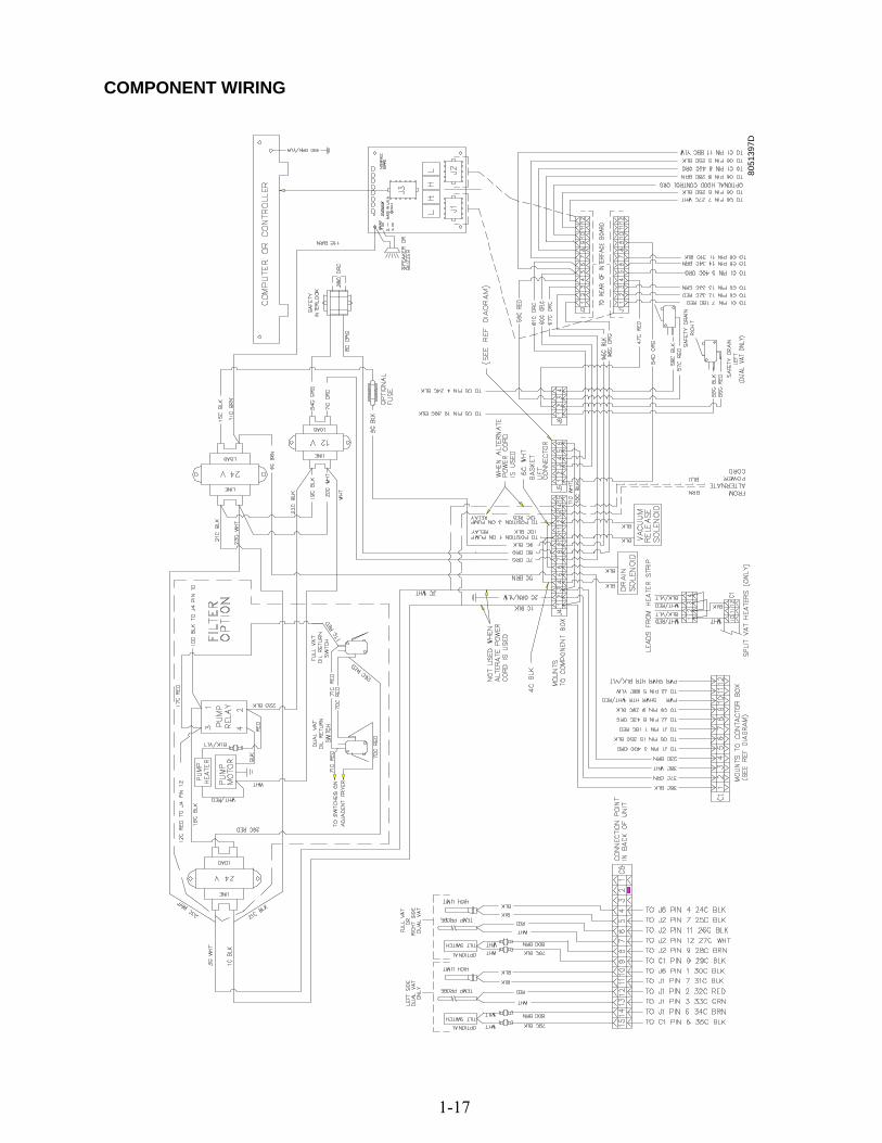
1.11 Wiring Diagrams
BASKET LIFT
1-17
COMPONENT WIRING
8051
397D

1-18
CONTACTOR BOX – DELTA CONFIGURATION

1-19
CONTACTOR BOX – WYE CONFIGURATION
8051
399C

2-1
PRO SERIES ELECTRIC FRYERS CHAPTER 2: PARTS LIST
2.1 Accessories
3
4
5
6
7 8
9
10 11
1
2
ITEM STANDARD PART #
EURO-LOOK PART # COMPONENT
1 809-0171 Thumbscrew, ¼ -20 X 13/8-inch 2 810-1403 Hanger, Wireform Basket * 809-0921 Spacer, Basket Hanger 3 803-0197 Cleanout Rod, 27-inch 4 803-0209 Brush, Frypot 5 823-1885 Connecting Strip, Frypot 6 806-3068 Cover, Full-Vat Frypot * 806-3071 Cover, Dual-Vat Frypot 7 803-0099 Basket, Full-Vat 8 803-0271 Basket, Dual-Vat (Twin) 9 803-0122 Sediment Tray, Left Dual-Vat * 803-0123 Sediment Tray, Right Dual-Vat * 803-0113 Sediment Tray, Full-Vat 10 803-0132 Rack, Full-Vat Basket Support 11 803-0106 Rack, Dual-Vat Basket Support * 803-0002 Powder, Filter (80 1-Cup Applications) * 803-0046 Cup, Plastic Measuring * 803-0170 Pack, 100-Sheet Filter Paper
* Not illustrated. Use standard part.

2-2
2.2 Basket Lift Assembly and Associated Parts
28
26
25 1
27
22
21
10
21
6
11
17
5
41
7
17
24
3 20
3 14
18
12
98
17
15
29
30
33
34
35
32
31

2-3
ITEM STANDARD PART #
EURO-LOOK PART # COMPONENT
106-1805SP Basket Lift Assembly, 200-220VAC w/Relay (Items 1-23) 1 810-1012 Rod, Basket Lift 2 813-0035 Bushing, Bronze 3 807-2513 Capacitor, 12.5 μFarad 330VAC 4 901-8499 Chassis, Left Basket Lift 5 902-8499 Chassis, Right Basket Lift 6 807-0159 Connector, 12-Pin Female 7 900-5529 Gusset, Basket Lift Motor 8 812-0442 Insulation, Microswitch 9 807-2572 Microswitch 10 806-5964SP Motor Assembly, 208-240VAC Modular Basket Lift 11 200-2942 Mount, Modular Basket Lift 12 826-1366 Nut, 4-40 Hex Keps (Pkg. of 25) 13 809-0247 Nut, 8-32 Hex Keps 14 807-1683 Relay, 12VDC 15 106-2770SP Resistor Assembly, 208-220VAC Modular Basket Lift * 106-2771SP Resistor Assembly, 230-250VAC Modular Basket Lift 16 809-0082 Ring, Bushing Retainer 17 826-1374 Screw, #10 X ½-inch Hex Washer Head (Pkg. of 25) 18 826-1359 Screw, 4-40 X ¾-inch Slotted Round Head (Pkg. of 25) 19 826-1361 Screw, 8-32 X 1-inch Slotted Truss Head (Pkg. of 25) 20 826-1371 Screw, #8 X ½-inch Drill Point Hex Head (Pkg. of 25) 21 809-0503 Screw, 8-32 X ½-inch Hex Head 22 809-0186 Washer, #8 Lock 23 WIR-0166SP Wire Bundle, 200-250VAC Basket Lift w/Relay 24 910-4776 Cover, Modular Basket Lift Rear S/S (Use 900-4776 for Mild Steel) 25 809-0127 Screw, ¼-20 X ½-inch Slotted Round Head 26 823-2704 Arm, Left Basket Lift 27 823-2705 Arm, Right Basket Lift 28 810-0179 Button, Plug 29 806-9110SP Roller Assembly, Basket Lift 30 910-8112 Bracket, Basket Lift Roller 31 810-0194 Roller, Basket Lift 32 810-0374 Spacer, Basket Lift Roller 33 809-0508 Bolt, ¼-20 X 1¼ -Inch 34 809-0190 Washer, ¼-inch Flat 35 809-0047 Nut, ¼-20 Cap * 807-3700 Wiring Harness, Pro Series Electric Basket Lift (Plugs into Item 6)
* Not illustrated. Use standard part.

2-4
2.3 Cabinetry 2.3.1 Back Panels, Control Panel Frames, Doors, Sides, Tilt Housings, and Top Caps
12
15
1
2
3
4
14
13
18 5
8
7
9
1011
6
1716

2-5
ITEM
STANDARD PART #
EURO-LOOKPART #
COMPONENT
1 Back Panel, Upper (Panel for five station fryer shown) 210-2299 200-6630 Two Station Fryer 210-2380 200-6785 Three Station Fryer 210-3490 200-6786 Four Station Fryer 210-3670 200-6787 Five Station Fryer 2 Back Panel, Center (Panel for five station fryer shown) 210-2298 200-2298 Two Station Fryer 210-2379 200-2379 Three Station Fryer 210-3489 200-3489 Four Station Fryer 210-3669 200-3669 Five Station Fryer 3 Back Panel, Lower (Panel for five station fryer shown) 210-4430 200-4426 Two Station Fryer 210-4431 200-4427 Three Station Fryer 210-4432 200-4428 Four Station Fryer 210-4433 200-4429 Five Station Fryer 4 Frame, Control Panel (Frame for five station fryer shown) 806-7172SP 106-4378 Two Station Fryer (use 106-5221SP for fryers mfd. After 6.22.05) 806-7173SP 106-4391 Three Station Fryer (use 106-5018SP for fryers mfd. After 6.22.05) 806-7174SP 106-4392 Four Station Fryer (use 106-5019 for fryers mfd. After 6.22.05) 106-2171SP 106-4393 Five Station Fryer (use 106-5020 for fryers mfd. After 6.22.05) 5 210-4435 Side, Standard Cabinet Left or Right 6 810-2346 810-1105 Magnet, Door 7 211-4616 201-8481 Side, Filter Ready Cabinet Left 8 212-4616 202-8481 Side, Filter Ready Cabinet Right 9 910-0889 Cover, 5-inch X 5-inch Access 10 910-0890 Cover, 5-inch X 7-inch Access 11 809-0359 Screw, #8 X ¼-inch Hex Washer Head 12 Tilt Housing (Housing for five station fryer shown) 824-1061 824-1303 Two Station 824-1062 824-1335 Three Station 824-1063 824-1336 Four Station 824-1065 824-1337 Five Station
13 826-1351 809-0015 Nut Retainer, ¼-20 (Pkg. of 10 – receives basket hanger thumbscrew) 14 Top Cap (Top cap for five station fryer shown) 106-3033SP 106-4414 Two Station (use 106-5196 for fryers mfd. After 6.22.05) 106-3035SP 106-4437 Three Station (use 106-5197 for fryers mfd. After 6.22.05) 106-3036SP 106-4439 Four Station (use 106-5198 for fryers mfd. After 6.22.05) 824-0890 106-4441 Five Station (use 106-5199 for fryers mfd. After 6.22.05)
15 806-6545SP 106-4397 Door, Left or Right (Left shown – move handle to opposite side for Right) 16 809-0266 Screw, #10 X ½-inch Phillips Truss Head 17 810-1422 210-6816 Handle, Wireform Door 18 106-0554 Pin Assembly, Door * 810-0275 Spring, Door Pin
* Not illustrated. Use standard part.

2-6
2.3.2 Cabinet Bases, Braces, and Associated Parts
1
2
20 4
16
6
5
3
31
19
29
30
17
See Page 2-28 for filter railsand associated hardware.
7
26
See Page 2-4 for cabinet sides.
21 23
2414
2410
2412
2410
11 24
9 24
2415
The 5-Station cabinet illustrated is typical of allPro Series Electric cabinets. All componentsused in Pro Series cabinets are identified, but notall components are used in every configuration.
27 28 32
27 28 33
8 25
282218
See Page 2-32 for rear bridgesupport/oil return manifold.

2-7
ITEM STANDARD PART #
EURO-LOOK PART # COMPONENT
1 106-1265SP Upright Assembly, Left 2 106-1266SP Upright Assembly, Right 3 200-1651 Support, Cross Cabinet 4 200-1659 Divider, Cabinet 5 200-2293 Brace, Single Station Lower 6 200-3774 Brace, Double Station Lower 7 Brace, Front Horizontal 200-2331 Two-Station Fryer 200-2296 Three-Station Fryer 200-2733 Four-Station Fryer 200-3590 Five-Station Fryer 8 Brace, Rear Horizontal 200-2284 Two-Station Fryer 200-2295 Three-Station Fryer 200-2725 Four-Station Fryer 200-3592 Five-Station Fryer 9 200-4422 Support, Contactor Box Right Station 3 or Station 5 10 201-4425 Support, Contactor Box Left Station 4 or Station 5 11 202-4425 Support, Contactor Box Right Station 3 12 200-4423 Support, Contactor Box Stations 3 and 4 13 200-4447 Support, Contactor Box Front to Rear 14 201-5369 Support, Contactor Box Station 2 15 202-5369 Support, Contactor Box Station 1 16 200-4424 Post, Door 17 810-2346 Magnet, Door 18 200-4786 Support, Oil Return Manifold 19 210-5595 Hinge, Door 20 210-1490 Bracket, Rear Support 21 900-1224 Bracket, Frypot 22 809-0131 Bolt, ¼-20 X ¾-inch Hex Head (also used w/Item 27 to mount filter rails) 23 826-1371 Screw, #8 X ½-inch Drill Point Hex Head (Pkg. of 25) 24 826-1330 Screw, 10-32 X ⅜-inch Slotted (Pkg. of 25, used to attach contactor box) 25 809-0256 Nut, 10-32 Keps Hex 26 809-0412 Screw, #10 X ½-inch Hex Washer Head (primary cabinet screw) 27 809-0417 Nut, ¼-20 Hex Flange 28 809-0429 Bolt, ¼-20 X 2-inch Hex Head 29 200-5417 Brace, Rear Channel Corner 30 Channel, Base Rear 200-5463 Two-Station Fryer 200-5538 Three-Station Fryer 200-5537 Four-Station Fryer 200-5536 Five-Station Fryer
31 824-1131 Channel, Base Side 32 810-0326 Caster with Brake 33 810-1494 Caster without Brake * 810-1234 Leg, Stainless Steel 8.5-inch Adjustable (mounts with Items 27 and 28) * 823-4386 Leg, Navy Shipboard (mounts with Items 27 and 28)
* Not Illustrated. Use standard part.

2-8
2.4 Drain System Components 2.4.1 Drain Tube Sections and Associated Parts
See Page 2-12 for Drain Valves
1
2
3
4
1
2
3
4
5
56 6
7 7
8
9
10
11
12
13
14
15
16
17
18
19
2022 2321

2-9
ITEM STANDARD
PART # ** COMPONENT 1 813-0284 Nipple, ¾ X 1-inch NPT 2 816-0092 Grommet, 1-inch Drain 3 826-1345 Washer, 1-inch Drain (Pkg. of 25) 4 809-0347 Nut, 1-inch NPT Retainer 5 809-0893 Nut, 8-32 High Crown Acorn 6 826-1348 Cover, Drain Cleanout (Pkg. of 5) 7 816-0021 Gasket, Drain Cleanout 8 Drain Tube, Left End Short 823-3380 Full-Vat 823-3379 Dual-Vat 9 Drain Tube, Right End Short 823-1551 Full-Vat 823-1549 Dual-Vat
10 Drain Outlet 823-3229 With Vacuum Breaker Vent 823-2336 Without Vacuum Breaker Vent
11 810-2492 Fitting, Quick-Connect Straight (receives Teflon vent tube) 12 Drain Tube, Left End Short Vented 823-2637 Full-Vat 823-2636 Dual-Vat
13 Drain Tube, Right End Long 823-1508 Full-Vat 823-1543 Dual-Vat
14 823-3675 Drain Tube, Spreader Cabinet Short 15 Drain Tube, Open End Short 823-0718 Full-Vat 823-0725 Dual-Vat
16 823-0731 Drain Tube, Spreader Cabinet Long 17 Drain Tube, Open End Long 823-0717 Full-Vat 823-0724 Dual-Vat
18 823-3674 Drain Outlet, Filter Magic Left 19 823-3673 Drain Outlet, Filter Magic Right 20 810-0396 Clamp 21 809-0401 Screw, 10-32 X ¾-inch Hex Head 22 809-0256 Nut, 10-32 Keps Hex 23 816-0032 Gasket * 826-0877 Kit, Square Drain Clamp (2 each of Items 20-22 and 1 of Item 23) * 811-1071 Tube, Teflon Vent
* Not illustrated. ** See page 2-11 for an Euro-Look parts list.
2-10
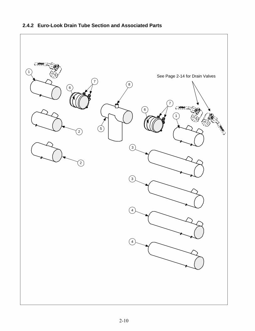
2.4.2 Euro-Look Drain Tube Section and Associated Parts
8
7
7
6
6
1
3
3
4
4
52
2
1
See Page 2-14 for Drain Valves

2-11
ITEM EURO-LOOK PART# ** COMPONENT
1 Drain Tube, Left/Right End Short 823-4625 Full-Vat 823-4624 Dual-Vat 2 Drain Tube, Left/Right Open Short 823-4643 Full-Vat 823-4642 Dual-Vat 3 Drain Tube, Right End Long 823-4639 Full-Vat 823-4638 Dual-Vat 4 Drain Tube, Left/Right Open Long 823-4641 Full-Vat 823-4640 Dual-Vat 5 823-4892 Drain Outlet 6 816-0625 Sleeve 7 809-0969 Clamp 8 810-2492 Fitting, Quick-Connect Straight (receives Teflon vent tube) * KIT6033 Kit, Round Drain Clamp (2 or Item 7 and 1 of Item 6) * 811-1071 Tube, Teflon Vent
* Not illustrated. ** See page 2-9 for a standard parts list.
2-12
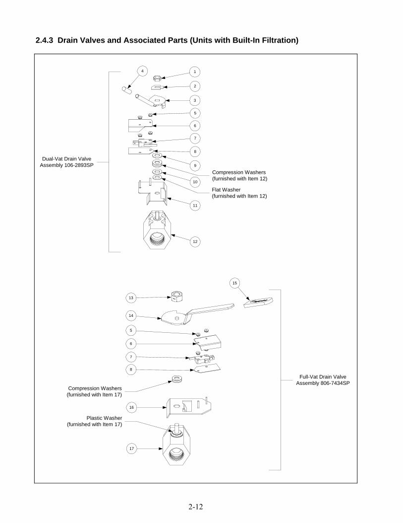
2.4.3 Drain Valves and Associated Parts (Units with Built-In Filtration)
Dual-Vat Drain ValveAssembly 106-2893SP
Full-Vat Drain ValveAssembly 806-7434SP
1
2
3
4
5
6
7
8
9
Compression Washers(furnished with Item 12)
10
Flat Washer(furnished with Item 12)
11
12
13
14
15
5
6
8
Compression Washers(furnished with Item 17)
16
Plastic Washer(furnished with Item 17)
17
7

2-13
ITEM STANDARD PART # **
COMPONENT
1 809-0539 Nut, ⅜-16 2-Way Hex Lock 2 900-2934 Retainer, Dual-Vat Drain Valve Nut 3 823-4133 Handle, Dual-Vat Drain Valve 4 810-0677 Grip, Drain Handle 5 809-0237 Nut, 4-40 Keps Hex 6 901-2348 Cover, Dual Vat Drain Safety Switch 7 807-2103 Microswitch, CE Straight Lever 8 816-0220 Insulation, Drain Safety Switch 9 810-1165 Washer, Teflon Drain Valve 10 809-0196 Washer, ⅜-inch Flat 11 106-2671SP Bracket Assembly, Dual-Vat Drain Safety Switch 12 810-1338 Valve, 1-inch Dual-Vat Drain 13 809-0540 Nut, ½-13 2-Way Hex Lock 14 900-2609 Handle, Full-Vat Drain Valve 15 814-0047 Sleeve, Red Handle 16 806-8137SP Bracket Assembly, Full-Vat Drain Safety Switch 17 810-1020 Valve, 1.25-inch Full-Vat Drain * WIR0572 Wire Bundle, Drain Safety Switch
* Not illustrated. ** See page 2-15 for a Euro-Look parts list.

2-14
2.4.4 Euro-Look Drain Valves and Associated Parts (Units with Built-In Filtration)
12
11
8
7
6
5
3
2
1
18
9
20
10
Compression Washers
4
Flat Washer
Plastic Washer
15
13
19
14
6
5
7
9
8
1816
20
17
Compression Washers
Dual-Vat Drain ValveAssembly 106-3761
Full-Vat Drain ValveAssembly 106-3760

2-15
ITEM EURO-LOOK PART # **
COMPONENT
1 809-0539 Nut, ⅜-16 2-Way Hex Lock 2 900-2934 Retainer, Dual-Vat Drain Valve Nut 3 823-4133 Handle, Dual-Vat Drain Valve 4 810-0677 Grip, Drain Handle 5 809-0237 Nut, 4-40 Keps Hex 6 901-2348 Cover, Dual Vat Drain Safety Switch 7 807-2103 Microswitch, CE Straight Lever 8 816-0220 Insulation, Drain Safety Switch 9 810-1165 Washer, Teflon Drain Valve 10 809-0196 Washer, ⅜-inch Flat 11 106-2671 Bracket Assembly, Dual-Vat Drain Safety Switch 12 810-1114 Valve, 1-inch Dual-Vat Drain 13 809-0540 Nut, ½-13 2-Way Hex Lock 14 900-2609 Handle, Full-Vat Drain Valve 15 814-0047 Sleeve, Red Handle 16 806-8137 Bracket Assembly, Full-Vat Drain Safety Switch 17 810-1018 Valve, 1.25-inch Full-Vat Drain 18 200-6496 Support, 3” Drain 19 900-2936 Retainer, Full-Vat Drain Valve Nut 20 816-0135 Round Drain O-Ring * WIR0572 Wire Bundle, Drain Safety Switch
* Not illustrated. ** See page 2-13 for a standard parts list.
2.4.5 Drain Valves and Associated Parts (Units without Built-In Filtration)
1
2
3
4
5
ITEM STANDARD PART #
EURO-LOOK PART # COMPONENT
1 810-1569 Valve, 1.25-inch Non-Filter Full-Vat Drain 2 806-7915SP Valve, 1-inch Non-Filter Dual-Vat Left Drain 3 806-7916SP Valve, 1-inch Non-Filter Dual-Vat Right Drain 4 812-1226 Drain Extension, 1.25-inch 5 812-1227 Drain Extension, 1-inch
Use standard part.

2-16
2.5 Electronics and Wiring Components
2.5.1 Component Boxes
20
8-24
0V C
E B
oxe
s 1
20V
, 44
0V N
avy,
an
d 4
80V
Bo
xes
208
-240
V N
ON
-CE
Box
es
6
1
7
242
5
7
1
7
20
66
1
202
202
98
1718
219
817
18
21
202
98
17
1821
1710
20
14
2012
142
0
1120
416
19
2022
911
2020
54
1619
20
229
102
020
5
91
320
1020
23
203
205
2220
41
619
NO
TE
1:
Th
e tr
ansf
orm
er
on
the
le
ft
side
o
f th
e co
mpo
nent
bo
x is
p
rese
nt
only
in
u
nits
w
ith
built
-in
filtr
atio
n a
nd th
en o
nly
in t
he le
ft co
mp
onen
t bo
x.
NO
TE
2:
Se
e P
age
2-2
3 f
or C
ompo
nent
Bo
x 15
-Pin
W
irin
g H
arn
esse
s.
26

2-17
ITEM STANDARD PART #
EURO-LOOKPART # COMPONENT
1 106-1531SP Box Assembly, Component 2 200-3300 Bracket, Component Box Strain Relief 3 200-3746 Bracket, Navy Circuit Breaker (US Navy units only) 4 806-9495SP Terminal Block and Wire Assembly 5 807-0012 Relay, 18 Amp ⅓ HP 24V Coil 6 807-0037 Terminal, ¼-inch Push-on 7 807-0121 Bushing, Heyco Plastic AB-625-500 8 807-1321 Holder, AGC Panel-Mount ¼-inch Fuse 9 807-1597 Fuse, 3 Amp Slow-Blow 10 807-2180 Transformer, 208-240V 50VA 11 807-2181 Transformer, 100-120V/24V 60VA 12 807-0680 Transformer, 208-240V/24V 20VA 13 807-2191 Transformer, 208-240V/12V 30VA 14 807-0855 Transformer, 100-120V/12V 20VA 15 807-0979 Transformer, 208-240V/12V 43VA 16 826-1366 Nut, 4-40 Keps Hex (Pkg. of 25) 17 809-0250 Nut, 6-32 Keps Hex 18 809-0349 Spacer, 4mm X 6mm Aluminum 19 826-1359 Screw, 4-40 X ¾-inch Slotted Round Head (Pkg. of 25) 20 809-0359 Screw, #8 X ¼-inch Hex Washer Head 21 Interface Board 806-6336SP Standard (Non-Triac), Full- or Dual-Vat 806-6347SP Triac, Full- or Dual-Vat 106-3721 Fast Computer, Full- or Dual-Vat * 807-3932 Relay, Heat and Latch 12 VDC SPDT 12A 22 806-7179SP Sound Device 23 807-0069 Circuit Breaker, 10 Amp 24 200-3844 Guard, Finger 25 810-2445 Plug Button 26 200-3243 Brace, Component Box
* Not illustrated. Use standard part.

2-18
2.5.2 Contactor Boxes
312713
12 35
4 35
3 35
8 29 32
17 18 36
361817
349
291110
19 28
OR20 28
32298
5 7 27 31 36
OR
6 35
36312775
OR
356
353
354
21
1 2
21
2
1
5 7 27 31 36
OR
6 35
4 35
3 35
8 29 32
12 35
312714
349
291110
356
12 35
17 18 36
361817
32298
361815
OR
361816
22 25 26
24 25 2623 18 36
WYE configurationsalso have Item 21,
mounted with Items 30and 33, here.
NOTE: See Pages 2-23 through 2-25 for Contactor Box Wiring Harnesses
STANDARD 14/17 kWCONFIGURATIONS
TRIACCONFIGURATIONS
22 kWCONFIGURATIONS
NAVYCONFIGURATIONS

2-19
NOTES: Left and right contactor box assemblies are mirror images of one another. With the exception of the box itself, all components of a left-hand assembly are the same as those in the corresponding right-hand assembly and vice versa. The configurations illustrated show all possible components, but a particular configuration may not have all the components shown.
ITEM STANDARD
PART # EURO-LOOK PART # COMPONENT
1 106-1536SP Box Assembly, Left Contactor 2 106-1537SP Box Assembly, Right Contactor 3 200-3111 Cover, Cord Cutout 4 900-2752 Plate, Cordset Adapter 5 200-2334 Door, Contactor Box Hinged 6 200-4712 Door, Contactor Box w/o Hinge 7 810-0519 Hinge, Contactor Box Door 8 807-0070 Terminal, Ground Lug 9 200-2336 Bracket, Contactor Box Fuse Block 10 807-0501 Fuse Block, 3-Pole 11 807-2240 Fuse, 60 Amp 300VAC 12 200-2337 Bracket, Mercury Contactor 13 807-1071 Contactor, 24V 30 Amp Mercury 14 807-0884 Contactor, 24V 35-50 Amp Mercury 15 807-2284 Contactor, 24V 50 Amp Mechanical (only in 14 & 17kW Navy units) 16 807-2283 Contactor, 24V 63 Amp Mechanical (only in 22kW Navy units) 17 810-1202 Contactor, 24V 40 Amp 3-Pole 18 809-0448 Clip, Tinnerman
19** 806-8674 Heatsink Assembly, DV Solid State Relay (See components below) 20** 806-8673 Heatsink Assembly, FV Solid State Relay (See components below)
21 806-9124 Filter Assembly, Triac (used in Wye-configured Triac units only) 22 807-0012 Relay, 18 Amp ⅓ HP 24V Coil 23 807-0064 Transformer, 480V/120V 150VA 24 807-1683 Relay, 12VDC 25 826-1358 Nut, 6-32 Keps Hex (Pkg. of 25) 26 826-1365 Screw, 6-32 X ⅜-inch Slot Head (Pkg. of 25) 27 809-0104 Screw, 8-32 X ½-inch Slot Head 28 826-1330 Screw. 10-32 X ⅜-inch Slot Head (Pkg. of 25) 29 809-0123 Screw, #10 X ¾-inch Slot Head 30 826-1366 Nut, 4-40 Keps Hex (Pkg. of 25) 31 809-0247 Nut, 8-32 Keps Hex 32 826-1376 Nut, 10-32 Keps Hex (Pkg. of 10) 33 826-1359 Screw, 4-40 X ¾-inch Slot Head (Pkg. of 25) 34 809-0359 Screw, #8 X ¼-inch Hex Washer Slot Head 35 809-0360 Screw, #8 X ⅜-inch Hex Washer Slot Head 36 826-1374 Screw, #10 X ½-inch Hex Head (Pkg. of 25) * 200-5627 Lid, Left or Right Contactor Box * Components of Items 19 and 20 ** 826-1562 Relay, Solid State 50 Amp 280V * 807-2749 Heatsink, Solid State * 807-0037 Terminal, ¼-inch Push-on * 809-0096 Screw, 6-32 X ⅝-inch Slot Head
** Not illustrated. ** Dual-vat Assembly has six relays (826-1562); full-vat Assembly has three relays.
Use standard part.

2-20
2.5.3 Heating Element Assemblies and Associated Parts
NOTES:The dual-vat assembly is the same as the full-vat assembly except for having two of Items 2, 12, 18 and 19, two of Item20 in place of Item 16, two of Item 21 in place of Item 17, and two of Item 10 instead of one Item 10 and one Item 11.The only difference between element assemblies for different voltage and kW ratings is the element itself (Item 1)
Items 23 and 24 are shown as associated parts. They are not part of either element assembly.
1
1
3
54
6
7
8
9
11
17
21
20
23
24
10
16
1413
15
19
18
1312
2
1
1
FULL-VAT ELEMENT ASSEMBLY DUAL-VAT ELEMENT ASSEMBLY
22

2-21
ITEM STANDARD PART #
EURO-LOOK PART # COMPONENT
1 Element 826-2151 200V 17.0 kW (also used for 220V 8.5 kW) 826-2156 200V 18.5 kW 826-2167 200V 11.0 kW 826-2149 208V 17.0 kW 826-2150 208V 18.5 kW 826-2172 208V 11.0 kW 826-2155 220V 17.0 kW (also used for 240V 8.5 kW) 826-2151 220V 18.5 kW (also used for 200V 7.0 kW) 826-2164 220V 11.0 kW 826-2152 230V 17.0 kW 826-2153 230V 18.5 kW 826-2165 230V 11.0 kW 826-2154 240V 17.0 kW 826-2155 240V 18.5 kW (also used for 220V 7.0 kW) 826-2166 240V 11.0 kW 826-2157 380V 17.0 kW 826-2158 380V 18.5 kW 826-2168 380V 11.0 kW 826-2159 440V 17.0 kW 826-2160 440V 18.5 kW 826-2169 440V 11.0 kW 826-2161 480V 17.0 kW 826-2162 480V 18.5 kW 826-2170 480V 11.0 kW
2 826-1526 Probe, Temperature 3 106-0004SP Tilt Plate Assembly 4 106-0572SP Bracket, Left Spring Slot 5 106-0573SP Bracket, Right Spring Slot 6 910-9641 Tilt Plate 7 810-0035 Hinge 8 826-1330 Screw, 10-32 X ⅜-inch Slotted Truss Head (Pkg. of 25) 9 826-1376 Nut, 10-32 Keps Hex (Pkg. of 10)
10 826-1339 Bushing, .375-inch Split (Pkg. of 10) 11 816-0480 Plug, .375-inch Dome 12 910-5022 Bracket, Temperature Probe 13 809-0518 Screw, 8-32 X ⅜-inch Slotted Hex Head 14 910-2042 Clamp, Element (Short) 15 910-5213 Clamp, Element (Long) 16 910-3681 Support, Full-Vat Element Rear 17 823-5621 Support, Full-Vat Element Front 18 810-1233 Handle, Element Lift 19 810-1212 Pin, .125 X .5-inch Split 20 910-5214 Support, Dual-Vat Element Rear 21 823-5627 Support, Dual-Vat Element Front 14kW, 17kW
230-4103 Support, Dual-Vat Element Front 22kW 22 809-0567 Tie-Wrap, Metal 23 200-2060 Bracket, Lower Spring Slot 24 810-0297 Spring, Element
* 826-1061 Tilt Switch, Mercury Non-CE (Full-Vat requires one switch and Dual-Vat requires two.)
* 826-2228 Magnetic Tilt Switch CE (Full-Vat requires one switch and Dual-Vat requires two.)
* Not illustrated. Use standard part.

2-22
2.5.4 Controllers
SOLID STATE
1 2 3 4
NOTE: See Page 2-27 for Interface Board to Controller Wiring Harness
ITEM STANDARD PART #
EURO-LOOK PART # COMPONENT
1 Computer Magic III.5 106-1193 106-4335 Full-Vat (CE) 106-1194 106-4336 Dual-Vat (CE) 806-7158SP 106-4373 Full-Vat (Non-CE) 806-7159SP 106-4374 Dual-Vat (Non-CE) 806-7162SP 106-4337 Full-Vat (Triac/Solid State) 806-7163SP 106-4338 Dual-Vat (Triac/Solid State) 2 Digital Controller 106-1507 106-4343 Full-Vat (CE) 106-1508 106-4344 Dual-Vat (CE) 106-1503 106-4339 Full-Vat (Non-CE) 106-1504 106-4340 Dual-Vat (Non-CE) 3 Basket Lift Timer 106-2090SP 106-4365 Full-Vat (CE) 106-2091SP 106-4366 Dual-Vat (CE) 106-2088SP 106-4363 Full-Vat (Non-CE) 106-2089SP 106-4364 Dual-Vat (Non-CE) 4 Solid-State (Analog) Controller 806-7422 106-4333 Full-Vat 806-7423 106-4334 Dual-Vat

2-23
2.5.5 Wiring 2.5.5.1 Contactor Box Wiring Assemblies – 12-Pin Dual-Vat C-1
1
2
BLACK
GREEN/YELLOW
WHITE
BROWN
ORANGE
BLACKW
HIT
E
BLA
CK
1
2
3
4
5
6
7
8
9
10
11
12
ORANGE
BLACK
BLACK
GREEN/YELLOW
WHITE
BROWN
ORANGE
BLACK
WH
ITE
BL
AC
K
1
2
3
4
5
6
7
8
9
10
11
12
ORANGE
BLACK
YELLOW
ITEM STANDARD PART #
EURO-LOOKPART # COMPONENT
1 106-2428SP Standard 2 106-2343SP Triac
Use standard part.

2-24
2.5.5.2 Contactor Box Wiring Assemblies – 12-Pin Full-Vat C-1
BLACK
GREEN/YELLOW
WHITE
BROWN
ORANGE
BLACK
WH
ITE
BL
AC
K
1
2
3
4
5
6
7
8
9
10
11
12
YELLOW
RED
BLACK
GREEN/YELLOW
WHITE
BROWN
ORANGE
BLACK
WH
ITE
BLA
CK
1
2
3
4
5
6
7
8
9
10
11
12
YELLOW
BLACK
GREEN/YELLOW
WHITE
BROWN
ORANGE
BLACKW
HIT
E
BL
AC
K
1
2
3
4
5
6
7
8
9
10
11
12
1
2
3
ITEM STANDARD PART #
EURO-LOOK PART # COMPONENT
1 Standard 106-2474SP Other than 480V 106-2522SP 480V 2 106-2475SP Triac 3 106-2477SP Navy
Use standard part.
2-25
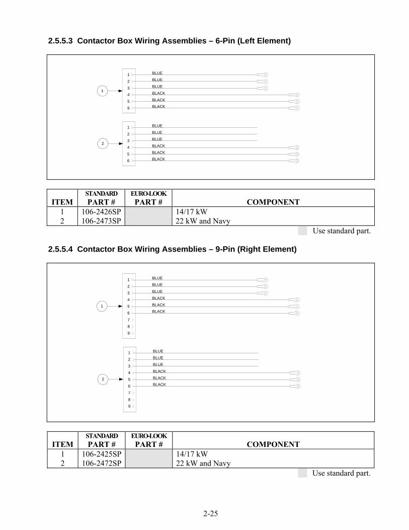
2.5.5.3 Contactor Box Wiring Assemblies – 6-Pin (Left Element)
1
2
BLUE
BLACK
1
2
3
4
5
6
BLACK
BLACK
BLUE
BLUE
BLUE
BLACK
1
2
3
4
5
6
BLACK
BLACK
BLUE
BLUE
ITEM STANDARD PART #
EURO-LOOK PART # COMPONENT
1 106-2426SP 14/17 kW 2 106-2473SP 22 kW and Navy
Use standard part. 2.5.5.4 Contactor Box Wiring Assemblies – 9-Pin (Right Element)
1
2
BLUE
BLACK
1
2
3
4
5
6
BLACK
BLACK
BLUE
BLUE
7
8
9
BLUE
BLACK
1
2
3
4
5
6
BLACK
BLACK
BLUE
BLUE
7
8
9
ITEM STANDARD PART #
EURO-LOOK PART # COMPONENT
1 106-2425SP 14/17 kW 2 106-2472SP 22 kW and Navy
Use standard part.

2-26
2.5.5.5 Main and Multi-Fryer Wiring Harnesses
12-Pin ConnectorWiring for 807-3716
12-Pin ConnectorWiring for 807-3717
12-Pin ConnectorWiring for 807-3718
Female Disconnect Pin807-0701
Male Disconnect Pin807-1049
Female Disconnect Pin807-0701
12-Pin Male Connector807-0160
Male Disconnect Pins807-1049
FRYER #4FRYER #3 FRYER #5
Item 3: 807-3716Item 4: 807-3717
Item 5: 807-3718
2
15-Pin Male Connector807-0804 (Rear of Fryer)
C6
12-Pin Male Connector807-0160 (Contactor Box)
C1
4-Pin Female Connector807-3232 (Drain Safety Switches)
J6
J1
J4
J5
J21
12-Pin Male Connector807-0160 (Interface Board)
12-Pin Male Connector807-0160 (Interface Board)
6-Pin Male Connector807-0157 (Basket Lift Harness)
15-Pin Male Connector807-0804 (Component Box)

2-27
ITEM STANDARD PART #
EURO-LOOK PART # COMPONENT
1 807-3769 Main 2 807-3715 Two-Fryer Battery 3 807-3716 Three-Fryer Battery 4 807-3717 Four-Fryer Battery 5 807-3718 Five-Fryer Battery
NOTE: Harnesses for 3-, 4-, and 5-Fryer batteries are similar to 807-3715 but have extra sets of leads as appropriate for the number of fryers in the battery. The connections to Fryer #1 J2 and J4 are the same for all.
Use standard part.
2.5.5.6 Component Box Wiring Harnesses – 15-Pin
1 2 3 4
ITEM STANDARD PART #
EURO-LOOK PART # COMPONENT
1 106-2506SP 208-480V (With Filter) 2 106-2507SP 208-480V (Without Filter) 3 106-2508SP 120V (With Filter) 4 106-2509SP 120V (Without Filter)
Use standard part. 2.5.5.7 Interface Board to Controller Wiring Harness – 15-Pin
806-2071SP

2-28
2.6 Filtration System Components
5
6
13
14
15
7
12119
121110
19
NOTE: Some early productionunits were configured this way.
38
16
30
29
2527
2624
23
18
24
18
36
37
3417
20
22
25
35
28
8
32
31
33
1
2
3
4
8
21

2-29
ITEM STANDARD PART #
EURO-LOOK PART # COMPONENT
* 826-1979 Filter Pan Roller Kit (four each of Items 7 and 8) * 826-1980 Service Filter Pan (Item 5 minus Item 2) * 826-1981 Service Filter Pan Assembly (Service Filter Pan above plus Items 3 and 4)* 826-1392 816-0012 O-Ring (Pkg. of 5; used with Item 5) * 813-0568 Plug, ⅛-inch Socket Head Pipe (component of Item 5; two required) * 811-1071 Tubing, ¼-inch OD Teflon Vent (sold by the foot) * 106-2851SP Heater Strip Assembly, 100-120V * 106-2852SP Heater Strip Assembly, 208-250V 1 823-4637 823-4787 Lid (for units built before Feb 2004, use 823-4391) 2 810-2874 Crumb Tray (component of Item 5) 3 810-2091 Hold-Down Ring (two are needed for pad hold-down option) 4 200-2124 SanaGrid Filter Screen 5 106-2617SP Pan, One-Piece Filter (includes Item 2) 6 810-2012 Rail Set, Filter Pan Roller (includes one left and one right) 7 810-2198 Roller, Filter Pan and Rail 8 826-1372 Nut, ¼-20 Hex (Pkg. of 10) 9 823-4589 823-4675 Bracket, Lid Support (for units built before Feb 04, use 823-3875) 10 Guide, Filter Pan Lid 200-3556 Left 200-6709 Right
11 809-0104 809-0503 Screw, 8-32 X ½-inch Slotted Truss Head 12 809-0247 Nut, 8-32 Hex Keps 13 823-3879 Suction Tube 14 200-4408 Rail, Left Filter 15 200-4409 Rail, Right Filter 16 Motor and Gasket Kit 826-1785 807-3858 100V 50/60 Hz 826-1712 807-3859 115V 50/60 Hz 826-1756 807-3860 208V 50/60 Hz 826-1757 807-3861 220-240V 50/60 Hz 826-1755 807-3862 250V 50/60 Hz
17 826-1264 Pump and Gasket Kit 810-2716 Pump, Viking 4GPM 2-piece 816-0093 Gasket, Pump/Motor
18 807-2484 Valve, ¼-inch Solenoid 19 813-0165 Elbow, ½-inch 90° Street 20 813-0342 Elbow, ½-inch 45° Street 21 813-0530 Tee, ½-inch X ¼-inch X ½-inch Reducing 22 813-0022 Nipple, ½-inch Close 23 813-0838 Nipple, ¼-inch Close 24 813-0304 Bushing, ½-inch to ¼-inch Flush 25 810-1668 Adapter, ⅝-inch to ½-inch NPT Male 26 810-1669 Adapter, ⅝-inch to ½-inch NPT Female 27 810-1680 Flexline, 6.5-inch Oil Return 28 810-1369 Flexline, 17.5-inch Oil Return
* Not illustrated. Use standard part.
Continued on next page…

2-30
29 810-1055 Flexline, 11.5-inch Oil Return 30 807-3828 Cable, FootPrint Pro Pump Motor 31 826-1375 809-0401 Screw, 10-32 X ¾-inch Hex Trim Head (Pkg. of 5) 32 200-7112 Bridge, Filter Motor 33 210-3149 Support, Contactor Box 34 813-0003 Tee, ½-Inch 35 813-0298 Nipple, ½-inch 2.0-inch 36 813-0537 Nipple, ¼-inch 2.0-inch 37 810-2493 Fitting, ¼-inch X 90° Quick-Connect 38 810-1160 Flexline, 3.0-inch Oil Return * 810-1043 Flexline, 9.5-inch Oil Return * 810-1057 Flexline, 13.0-inch Oil Return
* Not illustrated. Use standard part.

2-31
2.7 Frypot Assemblies and Associated Parts
1
2
3
3
4
4
4
4
4
5
5
7
6 8

2-32
ITEM PART# COMPONENT 1 823-4776SP Frypot, Full-vat 2 823-4779 Frypot, Dual-vat * 823-4747SP Frypot, Full-vat, Filter Magic * 823-4777 Frypot, Dual-vat, Filter Magic * 823-2452SP Frypot, Full-vat, EPRI/Triac (with insulation, 806-8167SP) * 823-2461 Frypot, Dual-vat, EPRI/Triac (with insulation, 106-4582SP) * 823-5001 Frypot, Full-vat, EPRI/Triac with Filter Magic (with insulation, 106-4575SP) * 823-5002 Frypot, Dual-vat, EPRI/Triac with Filter Magic (with insulation, 106-4576SP) 3 Thermostat Assembly, High-Limit 806-7543 Non-CE Full Vat 425°F (218°C) (Color-Coded Black) 806-8035 Non-CE Dual Vat 435°F (224°C) (Color-Coded Red) 806-8132 CE 415°F (213°C) used in 14 & 17kW fryers (Color-Coded Yellow) 806-8536 CE 405°F (207°C) used in 22 kW fryers (Color-Coded White) 4 812-0211 Insulation, Kaowool 17-inch X 10-inch X ½-inch (4 required per pot) 5 900-4100 Retainer, Side Insulation 6 900-4101 Retainer, Front Insulation 7 900-1345 Retainer, Rear Insulation 8 826-1376 Nut, 10-32 Keps Hex (Pkg. of 10)
* Not illustrated.

2-33
2.8 Oil Return System Components
1
3
4
5
6
26
8 14
10
11
12
13
9
15
1617
18
19
20
21
22
23
2
3
4
5
7
25
24

2-34
ITEM STANDARD PART #
EURO-LOOK PART # COMPONENT
1 806-4505SP Power Shower Assembly, Full-Vat 2 806-4527SP Power Shower Assembly, Dual-Vat 3 826-0992 Seal, Power Shower (Pkg. of 3) 4 809-0415 Screw, Power Shower Cleanout 5 814-0001 Grip, Power Shower Handle 6 823-1486 Power Shower, Full-Vat 7 823-1510 Power Shower, Dual-Vat 8 807-2103 Microswitch, Oil Return 9 810-2330 Handle, Oil Return Valve 10 809-0601 Clip, Clevis 11 810-0677 Grip, Oil Return Valve Handle 12 200-5401 Bracket, Handle Retainer 13 200-2520SP Bracket, Oil Return Microswitch 14 816-0220 Insulation, Oil Return Microswitch 15 826-1359 Screw, 4-40 X ¾-inch Slotted Pan Head (Pkg. of 25) 16 826-1366 Nut, 4-40 Keps Hex (Pkg. of 25) 17 813-0165 Elbow, ½-inch X 90° Street 18 810-0278 Valve, ½-inch Ball 19 810-1668 Adapter, ⅝-inch to ½-inch NPT Male 20 810-1680 Flexline, 6.5-inch 21 810-1669 Adapter, ⅝-inch to ½-inch NPT Female 22 813-0469 Cap, ½-inch NPT Pipe 23 810-2255 Manifold, Two-Station Fryer (use 810-2543 for non-filter units) 24 810-2256 Manifold, Three-Station Fryer (use 810-2544 for non-filter units)25 810-2257 Manifold, Four-Station Fryer (use 810-2545 for non-filter units) 26 810-2312 Manifold, Five-Station Fryer (use 810-2546 for non-filter units)
* Not illustrated. Use standard part.

Frymaster, L.L.C., 8700 Line Avenue, Shreveport, Louisiana 71106
TEL 1-318-865-1711 (Tech Support) 1-318-219-7135
PRINTED IN THE UNITED STATES SERVICE HOTLINE
1-800-551-8633
819-599003/2016