shipbuilding and ship repair surface coating neshap … · 2016-06-29 · shipbuilding and ship...
TRANSCRIPT
Shipbuilding and Ship Repair Surface Coating
NESHAP Compliance Inspection
How to Perform the Inspection
Atlantic Marine, Inc., Mobile, Alabama Shipyard
The Waste Reduction Resource Center 1639 Mail Service Center Raleigh, NC 27699-1639
October 15, 2003
i i
Ship Building and Ship Repair Surface Coating NESHAP Compliance Inspection
Table of Contents
Overview.........................................................................................................................1 Getting Ready for Inspection..........................................................................................4 Pre-Inspection Checklist .................................................................................................6 Inspection........................................................................................................................9 Inspection Checklist ......................................................................................................11 Data Collection .............................................................................................................15 Figuring Compliance.....................................................................................................19 P2 Opportunities in Shipyard Coating Operations ........................................................24 References .....................................................................................................................31 Tables Table 1. Volatile Organic HAP (VOHAP) Limits for Marine Coatings .......................2 Table 2. Summary of Recordkeeping and Reporting Requirements ...........................14 Table 3. Shipyard Marine Coating Expressions and Equations...................................19 Figures Figure 1. Compliance Options Flow Chart ....................................................................3 Figure 2 Example Shipyard Layout ..............................................................................9 Figure 3. Compliance Procedures Flow Chart.............................................................25
i ii
Appendices Appendix A National Emission Standards for Hazardous Air Pollutants for
Shipbuilding and Ship Repair (Surface Coating) Operations — 40 CFR Part 63 — Federal Register / Vol. 60 / No. 241, p. 64330
Appendix B Conducting Environmental Compliance Inspections, EPA Region 10 Appendix C A Guidebook on How to Comply with the Shipbuilding and Ship Repair
(Surface Coating) Operations National Emission Standards for Hazardous Air Pollutants, EPA 453/B-97-001
Appendix D 1. Method 24 – Determination of Volatile Matter Content, Density,
Volume of Solids and Weight of Solids of Surface Coatings, EPA-340/1-91-011
2. Standard Procedure for Collection of Coating and Ink Samples for Analysis by Reference Methods 24 and 24A, EPA-340/1-91-010
Appendix E Accredited Testing Laboratories (showing only laboratories accredited for
Clean Air Act (CAA) testing)
1
Shipbuilding and Ship Repair Surface Coating NESHAP Compliance Inspection
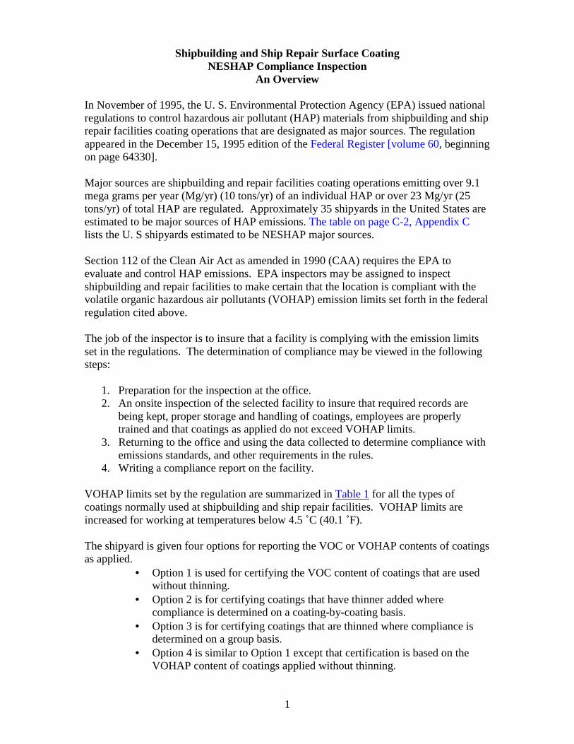
An Overview In November of 1995, the U. S. Environmental Protection Agency (EPA) issued national regulations to control hazardous air pollutant (HAP) materials from shipbuilding and ship repair facilities coating operations that are designated as major sources. The regulation appeared in the December 15, 1995 edition of the Federal Register [volume 60, beginning on page 64330]. Major sources are shipbuilding and repair facilities coating operations emitting over 9.1 mega grams per year (Mg/yr) (10 tons/yr) of an individual HAP or over 23 Mg/yr (25 tons/yr) of total HAP are regulated. Approximately 35 shipyards in the United States are estimated to be major sources of HAP emissions. The table on page C-2, Appendix C lists the U. S shipyards estimated to be NESHAP major sources. Section 112 of the Clean Air Act as amended in 1990 (CAA) requires the EPA to evaluate and control HAP emissions. EPA inspectors may be assigned to inspect shipbuilding and repair facilities to make certain that the location is compliant with the volatile organic hazardous air pollutants (VOHAP) emission limits set forth in the federal regulation cited above. The job of the inspector is to insure that a facility is complying with the emission limits set in the regulations. The determination of compliance may be viewed in the following steps:
1. Preparation for the inspection at the office. 2. An onsite inspection of the selected facility to insure that required records are
being kept, proper storage and handling of coatings, employees are properly trained and that coatings as applied do not exceed VOHAP limits.
3. Returning to the office and using the data collected to determine compliance with emissions standards, and other requirements in the rules.
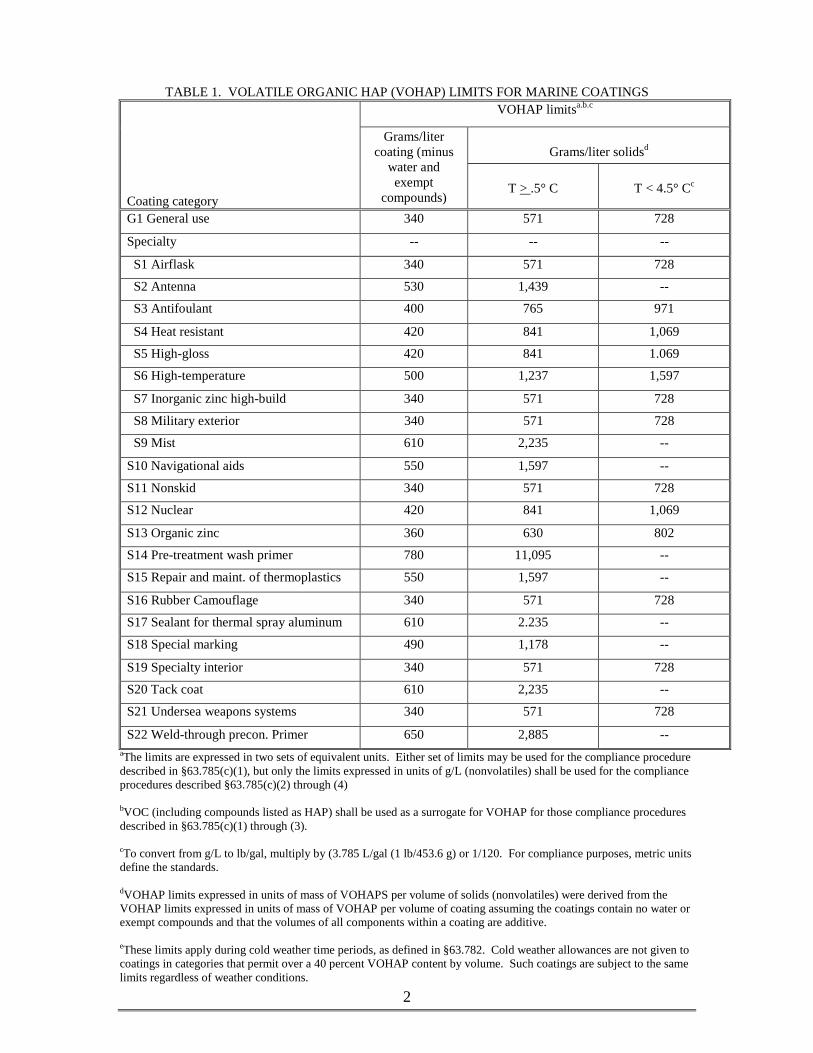
4. Writing a compliance report on the facility. VOHAP limits set by the regulation are summarized in Table 1 for all the types of coatings normally used at shipbuilding and ship repair facilities. VOHAP limits are increased for working at temperatures below 4.5 ˚C (40.1 ˚F). The shipyard is given four options for reporting the VOC or VOHAP contents of coatings as applied.
• Option 1 is used for certifying the VOC content of coatings that are used without thinning.
• Option 2 is for certifying coatings that have thinner added where compliance is determined on a coating-by-coating basis.
• Option 3 is for certifying coatings that are thinned where compliance is determined on a group basis.
• Option 4 is similar to Option 1 except that certification is based on the VOHAP content of coatings applied without thinning.
2
TABLE 1. VOLATILE ORGANIC HAP (VOHAP) LIMITS FOR MARINE COATINGS
VOHAP limitsa.b.c
Grams/liter solidsd
Coating category
Grams/liter coating (minus
water and exempt
compounds)
T > .5° C
T < 4.5° Cc
G1 General use 340 571 728
Specialty -- -- --
S1 Airflask 340 571 728
S2 Antenna 530 1,439 --
S3 Antifoulant 400 765 971
S4 Heat resistant 420 841 1,069
S5 High-gloss 420 841 1.069
S6 High-temperature 500 1,237 1,597
S7 Inorganic zinc high-build 340 571 728
S8 Military exterior 340 571 728
S9 Mist 610 2,235 --
S10 Navigational aids 550 1,597 --
S11 Nonskid 340 571 728
S12 Nuclear 420 841 1,069
S13 Organic zinc 360 630 802
S14 Pre-treatment wash primer 780 11,095 --
S15 Repair and maint. of thermoplastics 550 1,597 --
S16 Rubber Camouflage 340 571 728
S17 Sealant for thermal spray aluminum 610 2.235 --
S18 Special marking 490 1,178 --
S19 Specialty interior 340 571 728
S20 Tack coat 610 2,235 --
S21 Undersea weapons systems 340 571 728
S22 Weld-through precon. Primer 650 2,885 -- aThe limits are expressed in two sets of equivalent units. Either set of limits may be used for the compliance procedure described in §63.785(c)(1), but only the limits expressed in units of g/L (nonvolatiles) shall be used for the compliance procedures described §63.785(c)(2) through (4) bVOC (including compounds listed as HAP) shall be used as a surrogate for VOHAP for those compliance procedures described in §63.785(c)(1) through (3). cTo convert from g/L to lb/gal, multiply by (3.785 L/gal (1 lb/453.6 g) or 1/120. For compliance purposes, metric units define the standards. dVOHAP limits expressed in units of mass of VOHAPS per volume of solids (nonvolatiles) were derived from the VOHAP limits expressed in units of mass of VOHAP per volume of coating assuming the coatings contain no water or exempt compounds and that the volumes of all components within a coating are additive. eThese limits apply during cold weather time periods, as defined in §63.782. Cold weather allowances are not given to coatings in categories that permit over a 40 percent VOHAP content by volume. Such coatings are subject to the same limits regardless of weather conditions.
3
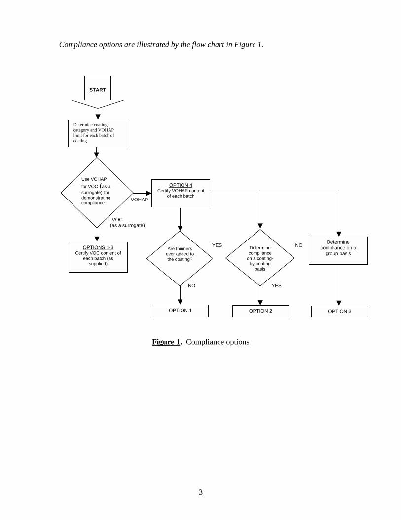
Compliance options are illustrated by the flow chart in Figure 1. VOHAP
VOC (as a surrogate)
YES NO
NO YES
Figure 1. Compliance options
START
Determine coating category and VOHAP limit for each batch of coating
Use VOHAP
for VOC (as a surrogate) for demonstrating compliance
Are thinners ever added to the coating?
Determine compliance
on a coating-by-coating
basis
OPTION 4 Certify VOHAP content
of each batch
OPTIONS 1-3 Certify VOC content of
each batch (as supplied)
Determine compliance on a
group basis
OPTION 1 OPTION 2 OPTION 3
4
Getting Ready for Inspection An inspector who has not been through recent training or is relatively inexperienced should study EPA Region 10’s training document for inspectors found in Appendix B. Additional comprehensive information for the inspector can also be found in Multi-Media Investigation Manual, US EPA Office of Enforcement EPA-330/9-89-003-R Inspectors are urged to conduct themselves in a professional manner and avoid conflict with the facility personnel. Keep in mind that your visit is simply to gather data to determine if the facility is in compliance. Compliance will be determined when you return to the office and analyze the data. The United States Environmental Protection Agency, Office of Air Quality, Planning and Standards, Research Triangle Park, NC 27711 has issued A Guidebook on How to Comply with the Shipbuilding and Ship Repair (Surface Coating) Operations National Emission Standards for Hazardous Air Pollutants, EPA 453/B-97-001, to instruct shipyards on how to comply with the emissions regulations. The inspector should become thoroughly familiar with this document, which is in Appendix C. The inspector who is not familiar with the shipbuilding and repair industry should review the EPA Sector Notebook, Profile of the Shipbuilding and Repair Industry, EPA/310-R-97-008. EPA Region 10’s training document suggests that about 50 percent of the inspector’s time may be required in preparation for the site visit. Regardless of the time required, plan to do as many things that can be done before the visit in order to save your time and the time of those you will see during the inspection. Check your files and review information about previous inspections. Things to look at are Title V annual certifications, semi-annual monitoring and periodic monitoring reports, and any other reports required by permit. Talk with personnel in the EPA Regional Office along with any State or Local Office having jurisdiction that have made previous inspections or have knowledge of the facility. EPA Region 4’s policy is to conduct “unannounced” inspections, except in special circumstances. This “unannounced” approach varies from state/local to state/local agency. Good record keeping is essential. A diary or a log of events that includes names, dates and time can be kept in a record book or on a laptop computer. In addition to ensuring the accuracy of your report, detailed records could be needed to support your findings in case of a violation.

5
Sampling and laboratory testing must also be carried out using standard methods. The use of standard methods ensures that results of the tests can withstand legal scrutiny. Finally, use the Pre-Inspection Checklist (following this section) to be certain that all bases have been covered.
6
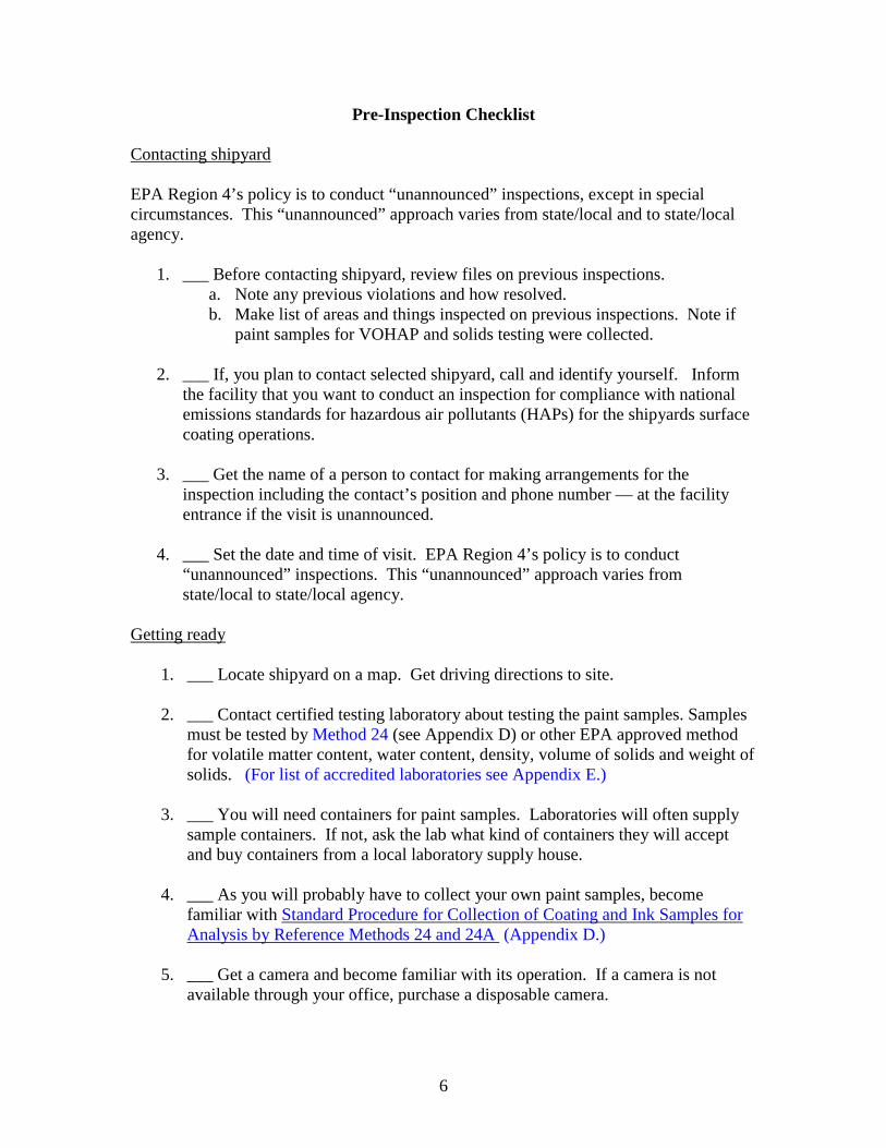
Pre-Inspection Checklist
Contacting shipyard EPA Region 4’s policy is to conduct “unannounced” inspections, except in special circumstances. This “unannounced” approach varies from state/local and to state/local agency.
1. ___ Before contacting shipyard, review files on previous inspections.
a. Note any previous violations and how resolved. b. Make list of areas and things inspected on previous inspections. Note if
paint samples for VOHAP and solids testing were collected.
2. ___ If, you plan to contact selected shipyard, call and identify yourself. Inform the facility that you want to conduct an inspection for compliance with national emissions standards for hazardous air pollutants (HAPs) for the shipyards surface coating operations.
3. ___ Get the name of a person to contact for making arrangements for the
inspection including the contact’s position and phone number — at the facility entrance if the visit is unannounced.
4. ___ Set the date and time of visit. EPA Region 4’s policy is to conduct
“unannounced” inspections. This “unannounced” approach varies from state/local to state/local agency.
Getting ready
1. ___ Locate shipyard on a map. Get driving directions to site.
2. ___ Contact certified testing laboratory about testing the paint samples. Samples must be tested by Method 24 (see Appendix D) or other EPA approved method for volatile matter content, water content, density, volume of solids and weight of solids. (For list of accredited laboratories see Appendix E.)
3. ___ You will need containers for paint samples. Laboratories will often supply
sample containers. If not, ask the lab what kind of containers they will accept and buy containers from a local laboratory supply house.
4. ___ As you will probably have to collect your own paint samples, become
familiar with Standard Procedure for Collection of Coating and Ink Samples for Analysis by Reference Methods 24 and 24A (Appendix D.)
5. ___ Get a camera and become familiar with its operation. If a camera is not
available through your office, purchase a disposable camera.
7
6. ___ Assemble your safety equipment. If safety equipment is not provided by your office, it can usually be purchased locally. Most installations will require safety shoes, hardhat, eye protection and often hearing protection in some areas of the installation.
7. ___ Wear comfortable clothing suitable for an industrial setting. If you are going
to collect paint samples, take rubber gloves to protect your hands.
8. ___ Get a cart or hand truck to carry your equipment.
9. ___ Bring your identification and a name tag.
8
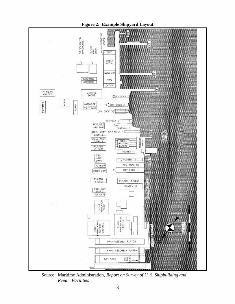
Figure 2: Example Shipyard Layout
Source: Maritime Administration, Report on Survey of U. S. Shipbuilding and
Repair Facilities
9
The Inspection The inspector should try to arrive at the shipyard location the day before the scheduled appointment. This time should be spent out side the facility locating the site to get a lay-of-the-land and to avoid delays in arriving at the appointed time. In meeting the contact and other people at the site it is important to act in a professional manner and maintain a friendly attitude. The objective is to induce the site personnel to cooperate more readily and to complete the inspection in a timely manner. The purpose of the visit is to gather information so that compliance can be determined. Compliance will be determined once the inspector returns to his or her office, has samples of coating analyzed, completes the necessary calculations and writes an inspection report. At the end of the visit, it is recommended that the inspector not venture an opinion regarding compliance, as this will be determined only after the data is analyzed. The overall objectives of your investigation should include:
• Determine compliance status with applicable laws, regulations, permits, and Consent Decrees.
• Determine ability of a facility to achieve compliance.
• Identify need for remedial measures and enforcement action(s) to correct the cause of violations
• Evaluate a facility's waste: producing, treatment, management, and pollution
control practices and equipment.
• Evaluate facility self-monitoring capability.
• Evaluate facility recordkeeping practices.
• Evaluate facility waste minimization/pollution prevention programs.
• Obtain appropriate samples. The inspector also needs to know how to deal with denial of entry situations. Whenever entry consent is denied (or withdrawn during the course of the inspection), the inspector should explain the Agency authority to conduct the investigation and verify that the facility representative understands the authority. If the person persists in denying entry or withdrawing consent, the inspector needs to fully document the circumstances and actions taken; this includes recording the name,

10
title, and telephone number of the person denying entry or withdrawing consent. The inspector must never make threatening remarks to facility personnel. Denied entry, the inspector should then contact his/her supervisor and Agency legal counsel. If the inspector and the supervisor suspect that a warrant will be necessary before entry is attempted, then actions to obtain a warrant should be initiated.
11
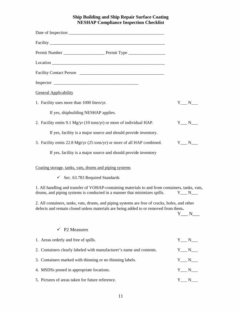
Ship Building and Ship Repair Surface Coating NESHAP Compliance Inspection Checklist
Date of Inspection ____________________________________________ Facility _____________________________________________________ Permit Number ___________________ Permit Type _________________ Location ____________________________________________________ Facility Contact Person _______________________________________ Inspector _______________________________________ General Applicability 1. Facility uses more than 1000 liters/yr. Y___ N___
If yes, shipbuilding NESHAP applies. 2. Facility emits 9.1 Mg/yr (10 tons/yr) or more of individual HAP. Y___ N___
If yes, facility is a major source and should provide inventory. 3. Facility emits 22.8 Mgt/yr (25 tons/yr) or more of all HAP combined. Y___ N___
If yes, facility is a major source and should provide inventory Coating storage, tanks, vats, drums and piping systems
! Sec. 63.783 Required Standards 1. All handling and transfer of VOHAP-containing materials to and from containers, tanks, vats, drums, and piping systems is conducted in a manner that minimizes spills. Y___ N___ 2. All containers, tanks, vats, drums, and piping systems are free of cracks, holes, and other defects and remain closed unless materials are being added to or removed from them. Y___ N___
! P2 Measures 1. Areas orderly and free of spills. Y___ N___ 2. Containers clearly labeled with manufacturer’s name and contents. Y___ N___ 3. Containers marked with thinning or no thinning labels. Y___ N___ 4. MSDSs posted in appropriate locations. Y___ N___ 5. Pictures of areas taken for future reference. Y___ N___
12
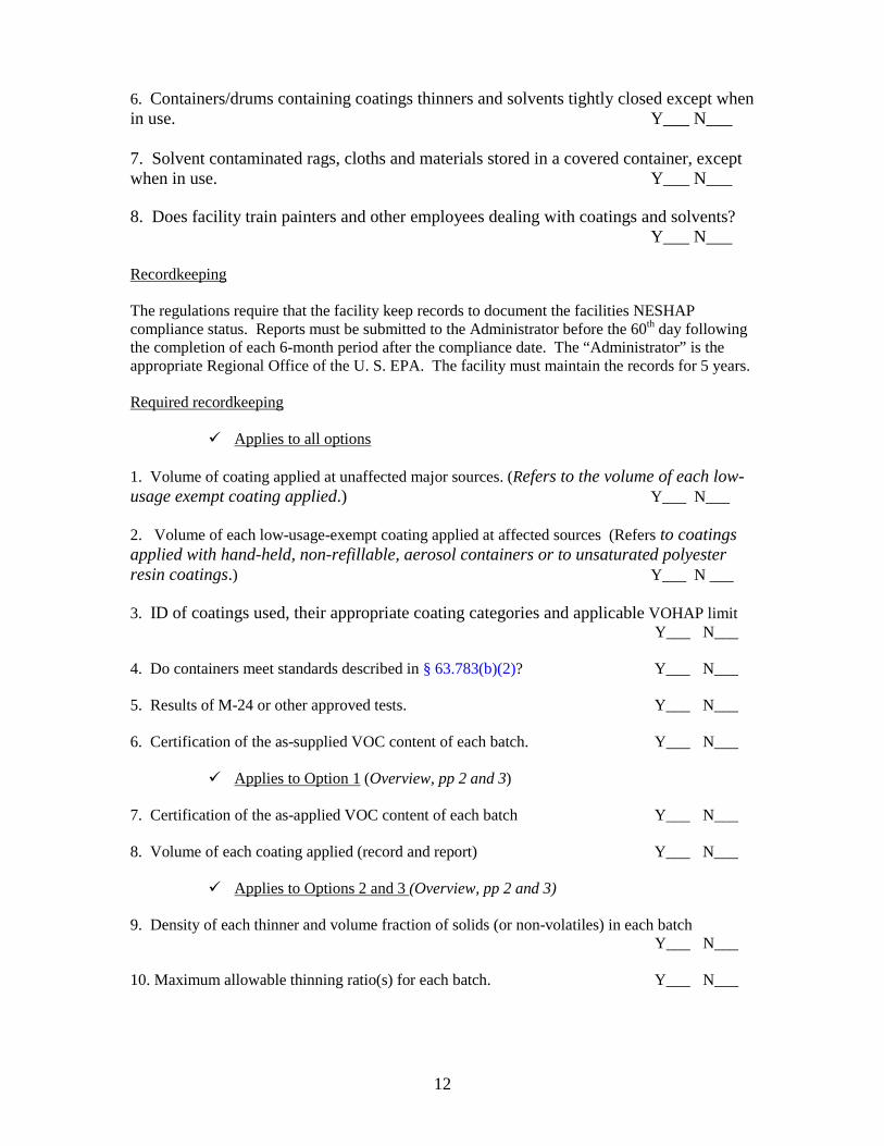
6. Containers/drums containing coatings thinners and solvents tightly closed except when in use. Y___ N___ 7. Solvent contaminated rags, cloths and materials stored in a covered container, except when in use. Y___ N___ 8. Does facility train painters and other employees dealing with coatings and solvents? Y___ N___ Recordkeeping The regulations require that the facility keep records to document the facilities NESHAP compliance status. Reports must be submitted to the Administrator before the 60th day following the completion of each 6-month period after the compliance date. The “Administrator” is the appropriate Regional Office of the U. S. EPA. The facility must maintain the records for 5 years. Required recordkeeping
! Applies to all options
1. Volume of coating applied at unaffected major sources. (Refers to the volume of each low-usage exempt coating applied.) Y___ N___
2. Volume of each low-usage-exempt coating applied at affected sources (Refers to coatings applied with hand-held, non-refillable, aerosol containers or to unsaturated polyester resin coatings.) Y___ N ___ 3. ID of coatings used, their appropriate coating categories and applicable VOHAP limit Y___ N___
4. Do containers meet standards described in § 63.783(b)(2)? Y___ N___
5. Results of M-24 or other approved tests. Y___ N___
6. Certification of the as-supplied VOC content of each batch. Y___ N___
! Applies to Option 1 (Overview, pp 2 and 3)
7. Certification of the as-applied VOC content of each batch Y___ N___
8. Volume of each coating applied (record and report) Y___ N___
! Applies to Options 2 and 3 (Overview, pp 2 and 3)
9. Density of each thinner and volume fraction of solids (or non-volatiles) in each batch Y___ N___ 10. Maximum allowable thinning ratio(s) for each batch. Y___ N___
13
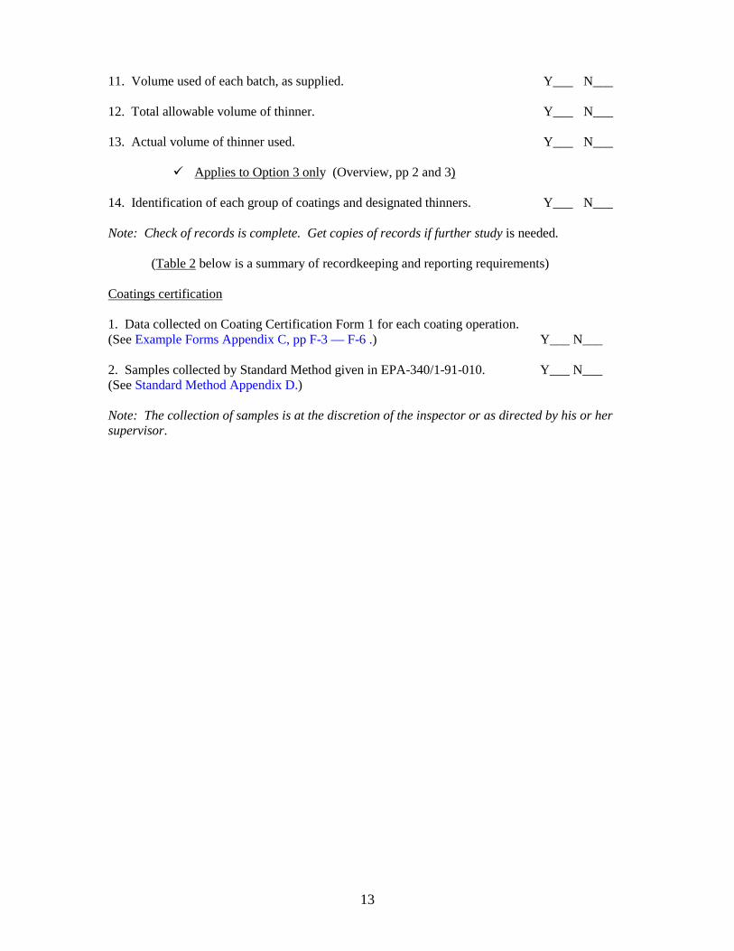
11. Volume used of each batch, as supplied. Y___ N___ 12. Total allowable volume of thinner. Y___ N___
13. Actual volume of thinner used. Y___ N___
! Applies to Option 3 only (Overview, pp 2 and 3)
14. Identification of each group of coatings and designated thinners. Y___ N___ Note: Check of records is complete. Get copies of records if further study is needed.
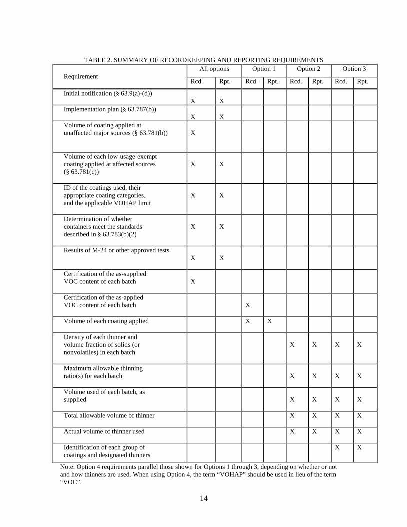
(Table 2 below is a summary of recordkeeping and reporting requirements)
Coatings certification 1. Data collected on Coating Certification Form 1 for each coating operation. (See Example Forms Appendix C, pp F-3 — F-6 .) Y___ N___ 2. Samples collected by Standard Method given in EPA-340/1-91-010. Y___ N___ (See Standard Method Appendix D.) Note: The collection of samples is at the discretion of the inspector or as directed by his or her supervisor.
14
TABLE 2. SUMMARY OF RECORDKEEPING AND REPORTING REQUIREMENTS All options Option 1 Option 2 Option 3
Requirement Rcd. Rpt. Rcd. Rpt. Rcd. Rpt. Rcd. Rpt.
Initial notification (§ 63.9(a)-(d)) X
X
Implementation plan (§ 63.787(b))
X
X
Volume of coating applied at unaffected major sources (§ 63.781(b))
X
Volume of each low-usage-exempt coating applied at affected sources (§ 63.781(c))
X
X
ID of the coatings used, their appropriate coating categories, and the applicable VOHAP limit
X
X
Determination of whether containers meet the standards described in § 63.783(b)(2)
X
X
Results of M-24 or other approved tests X
X
Certification of the as-supplied VOC content of each batch
X
Certification of the as-applied VOC content of each batch
X
Volume of each coating applied
X
X
Density of each thinner and volume fraction of solids (or nonvolatiles) in each batch
X
X
X
X
Maximum allowable thinning ratio(s) for each batch
X
X
X
X
Volume used of each batch, as supplied
X
X
X
X
Total allowable volume of thinner
X
X
X
X
Actual volume of thinner used
X X X X
Identification of each group of coatings and designated thinners
X
X
Note: Option 4 requirements parallel those shown for Options 1 through 3, depending on whether or not and how thinners are used. When using Option 4, the term “VOHAP” should be used in lieu of the term “VOC”.
15
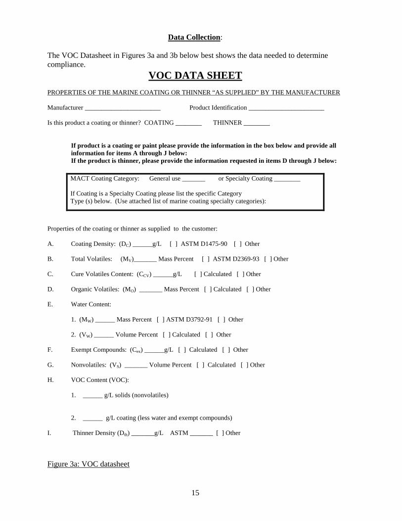
Data Collection: The VOC Datasheet in Figures 3a and 3b below best shows the data needed to determine compliance.
VOC DATA SHEET PROPERTIES OF THE MARINE COATING OR THINNER “AS SUPPLIED” BY THE MANUFACTURER Manufacturer _______________________ Product Identification _______________________ Is this product a coating or thinner? COATING ________ THINNER ________
If product is a coating or paint please provide the information in the box below and provide all information for items A through J below: If the product is thinner, please provide the information requested in items D through J below:
Properties of the coating or thinner as supplied to the customer: A. Coating Density: (DC) ______g/L [ ] ASTM D1475-90 [ ] Other B. Total Volatiles: (MV)_______ Mass Percent [ ] ASTM D2369-93 [ ] Other C. Cure Volatiles Content: (CCV) ______g/L [ ] Calculated [ ] Other D. Organic Volatiles: (MO) _______ Mass Percent [ ] Calculated [ ] Other E. Water Content: 1. (MW) ______ Mass Percent [ ] ASTM D3792-91 [ ] Other 2. (VW) ______ Volume Percent [ ] Calculated [ ] Other F. Exempt Compounds: (Cex) ______g/L [ ] Calculated [ ] Other G. Nonvolatiles: (VS) _______ Volume Percent [ ] Calculated [ ] Other H. VOC Content (VOC):
1. ______ g/L solids (nonvolatiles)
2. ______ g/L coating (less water and exempt compounds)
I. Thinner Density (Dth) _______g/L ASTM _______ [ ] Other
Figure 3a: VOC datasheet
MACT Coating Category: General use _______ or Specialty Coating ________ If Coating is a Specialty Coating please list the specific Category Type (s) below. (Use attached list of marine coating specialty categories):
16
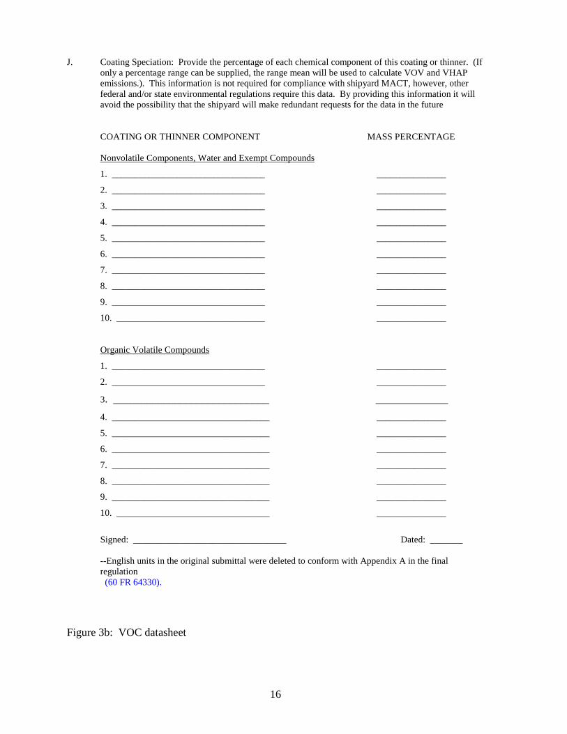
J. Coating Speciation: Provide the percentage of each chemical component of this coating or thinner. (If
only a percentage range can be supplied, the range mean will be used to calculate VOV and VHAP emissions.). This information is not required for compliance with shipyard MACT, however, other federal and/or state environmental regulations require this data. By providing this information it will avoid the possibility that the shipyard will make redundant requests for the data in the future COATING OR THINNER COMPONENT MASS PERCENTAGE Nonvolatile Components, Water and Exempt Compounds
1. _________________________________ _______________
2. _________________________________ _______________
3. _________________________________ _______________
4. _________________________________ _______________
5. _________________________________ _______________
6. _________________________________ _______________
7. _________________________________ _______________
8. _________________________________ _______________
9. _________________________________ _______________
10. ________________________________ _______________
Organic Volatile Compounds
1. _________________________________ _______________
2. _________________________________ _______________
3. ____________________________ _____________
4. __________________________________ _______________
5. __________________________________ _______________
6. __________________________________ _______________
7. __________________________________ _______________
8. __________________________________ _______________
9. __________________________________ _______________
10. _________________________________ _______________
Signed: _________________________________ Dated: _______ --English units in the original submittal were deleted to conform with Appendix A in the final regulation (60 FR 64330).
Figure 3b: VOC datasheet
17
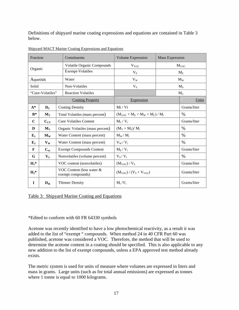
Definitions of shipyard marine coating expressions and equations are contained in Table 3 below. Shipyard MACT Marine Coating Expressions and Equations
Fraction Constituents Volume Expression Mass Expression
Volatile Organic Compounds VVOC MVOC Organic
Exempt-Volatiles VE ME
Aqueous Water VW MW Solid Non-Volatiles VS MS “Cure-Volatiles” Reaction Volatiles MC
Coating Property Expression Units
A* DC Coating Density Mi / Vi Grams/liter
B* MT Total Volatiles (mass percent) (MVOC + ME + MW + MC) / Mi % C CCV Cure Volatiles Content MC / Vi Grams/liter
D MV Organic Volatiles (mass percent) (MV + ME)/ Mi % E1 MW Water Content (mass percent) MW / Mi % E2 VW Water Content (mass percent) VW / Vi % F Cex Exempt Compounds Content ME / Vi Grams/liter
G VS Nonvolatiles (volume percent) VS / Vi % H1* VOC content (nonvolatiles) (MVOC) / VS Grams/liter
H2* VOC Content (less water & exempt compounds) (MVOC) / (VS + VVOC) Grams/liter
I Dth Thinner Density Mi /Vi Grams/liter
Table 3: Shipyard Marine Coating and Equations *Edited to conform with 60 FR 64330 symbols Acetone was recently identified to have a low photochemical reactivity, as a result it was added to the list of “exempt “ compounds. When method 24 in 40 CFR Part 60 was published, acetone was considered a VOC. Therefore, the method that will be used to determine the acetone content in a coating should be specified. This is also applicable to any new addition to the list of exempt compounds, unless a EPA approved test method already exists. The metric system is used for units of measure where volumes are expressed in liters and mass in grams. Large units (such as for total annual emissions) are expressed as tonnes where 1 tonne is equal to 1000 kilograms.
18
Data sources: Sources for the data needed to figure compliance are
• Provided to the shipyard by the coating supplier using Method 24 or other test methods accepted by the EPA,
• Tests on coating run by the shipyard using Method 24 or other test methods accepted by the EPA,
• Records maintained by the shipyard (see example records in App. C, pp F3 – F6), or • The testing of samples gathered by the inspector at an accredited testing laboratory
using Method 24 or other test method accepted by the EPA.
19
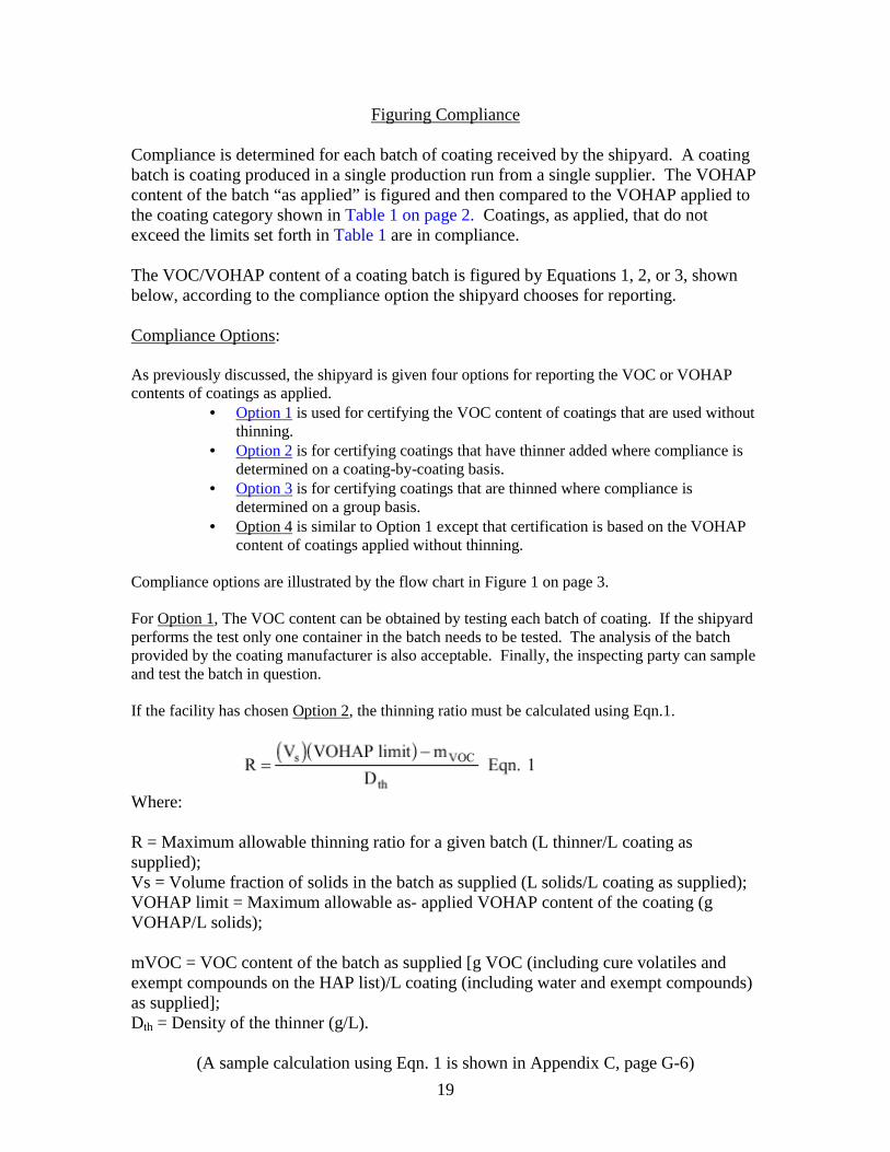
Figuring Compliance Compliance is determined for each batch of coating received by the shipyard. A coating batch is coating produced in a single production run from a single supplier. The VOHAP content of the batch “as applied” is figured and then compared to the VOHAP applied to the coating category shown in Table 1 on page 2. Coatings, as applied, that do not exceed the limits set forth in Table 1 are in compliance. The VOC/VOHAP content of a coating batch is figured by Equations 1, 2, or 3, shown below, according to the compliance option the shipyard chooses for reporting. Compliance Options: As previously discussed, the shipyard is given four options for reporting the VOC or VOHAP contents of coatings as applied.
• Option 1 is used for certifying the VOC content of coatings that are used without thinning.
• Option 2 is for certifying coatings that have thinner added where compliance is determined on a coating-by-coating basis.
• Option 3 is for certifying coatings that are thinned where compliance is determined on a group basis.
• Option 4 is similar to Option 1 except that certification is based on the VOHAP content of coatings applied without thinning.
Compliance options are illustrated by the flow chart in Figure 1 on page 3. For Option 1, The VOC content can be obtained by testing each batch of coating. If the shipyard performs the test only one container in the batch needs to be tested. The analysis of the batch provided by the coating manufacturer is also acceptable. Finally, the inspecting party can sample and test the batch in question. If the facility has chosen Option 2, the thinning ratio must be calculated using Eqn.1.
Where: R = Maximum allowable thinning ratio for a given batch (L thinner/L coating as supplied); Vs = Volume fraction of solids in the batch as supplied (L solids/L coating as supplied); VOHAP limit = Maximum allowable as- applied VOHAP content of the coating (g VOHAP/L solids); mVOC = VOC content of the batch as supplied [g VOC (including cure volatiles and exempt compounds on the HAP list)/L coating (including water and exempt compounds) as supplied]; Dth = Density of the thinner (g/L).
(A sample calculation using Eqn. 1 is shown in Appendix C, page G-6)
20
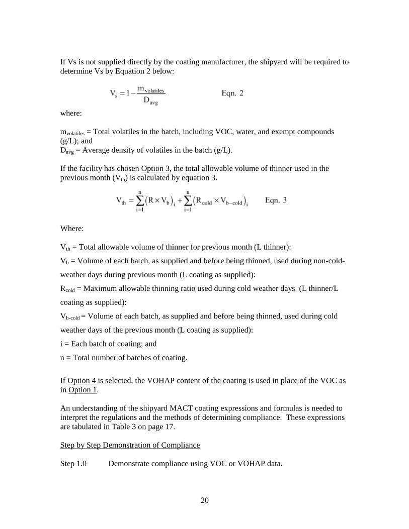
If Vs is not supplied directly by the coating manufacturer, the shipyard will be required to determine Vs by Equation 2 below:
where: mvolatiles = Total volatiles in the batch, including VOC, water, and exempt compounds (g/L); and Davg = Average density of volatiles in the batch (g/L). If the facility has chosen Option 3, the total allowable volume of thinner used in the previous month (Vth) is calculated by equation 3.
Where: Vth = Total allowable volume of thinner for previous month (L thinner):
Vb = Volume of each batch, as supplied and before being thinned, used during non-cold-
weather days during previous month (L coating as supplied):
Rcold = Maximum allowable thinning ratio used during cold weather days (L thinner/L
coating as supplied):
Vb-cold = Volume of each batch, as supplied and before being thinned, used during cold
weather days of the previous month (L coating as supplied):
i = Each batch of coating; and
n = Total number of batches of coating.
If Option 4 is selected, the VOHAP content of the coating is used in place of the VOC as in Option 1. An understanding of the shipyard MACT coating expressions and formulas is needed to interpret the regulations and the methods of determining compliance. These expressions are tabulated in Table 3 on page 17. Step by Step Demonstration of Compliance Step 1.0 Demonstrate compliance using VOC or VOHAP data.
21
Step 2.0 Set up a coating and thinning solvent database: determine category, VOHAP limit and VOC/VOHAP content of each batch of coating as supplied.
Step 3.0 Depending whether or not thinning solvents are added, determine
compliance option.
Option 1
Step 4.1 Certify VOC/VOHAP content of each batch. Step 5.1 Ascertain if painters properly notified that no thinning solvent may be
added. View record of notification. Step 6.1 View monthly record of VOC/VOHAP content of coating. (Compliance is demonstrated if allowable limits not exceeded) Option 2
Step 4.2 Determine volume of solids and maximum allowable thinning ratio for
each batch. (Use Equations 1 and 2 as required) Step 5.2 Determine notification of painters maximum allowable thinning ratio for
specified solvent. View record of notification. Step 6.2 View “as supplied” volume for each batch thinned in the previous month. Step 7.2 View allowable amount of thinning solvent for each coating thinned
during previous month. (Use Equation 3.) Step 8.2 View monthly records show in the volume of thinner added to each batch
of coating and that it does not exceed allowable volume. (Compliance is demonstrated if volume of thinner does not exceed allowable volume)
Option 3
Step 4.3 Group all coatings using the same thinner type. Step 5.3 Figure nonvolatile solids and maximum thinning ratio for each batch of
coating. (Use Equations 1 and 2 as needed) Step 6.3 View notification to painters of amount of solvent that can be added so as
not to exceed maximum allowable ratio. Step 7.3 Determine as supplied volume of thinner of each batch of coating during
previous month.
22
Step 8.3 Determine the total volume of thinning solvent used for each coating thinned during the previous month using Equation 3.
Step 9.3 View monthly records that volume of thinner does not exceed allowable
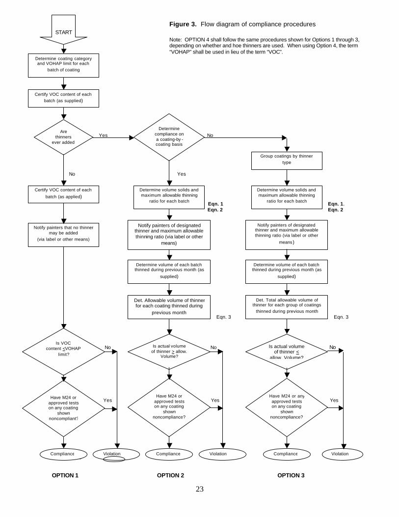
volume. (Compliance is demonstrated if allowable volume of solvent not exceeded.) Compliance procedures are outlined by the flow diagram in Figure 3.
23
Figure 3. Flow diagram of compliance procedures
Note: OPTION 4 shall follow the same procedures shown for Options 1 through 3, depending on whether and hoe thinners are used. When using Option 4, the term “VOHAP” shall be used in lieu of the term “VOC”.
Yes No
No Yes
Eqn. 1 Eqn. 1. Eqn. 2 Eqn. 2 Eqn. 3 Eqn. 3 No No No Yes Yes Yes
Yes Yes Yes No No No
OPTION 1 OPTION 2 OPTION 3
START
Determine coating category and VOHAP limit for each
batch of coating
Certify VOC content of each batch (as supplied)
Are thinners
ever added to the
Determine compliance on a coating-by -coating basis
Certify VOC content of each
batch (as applied)
Notify painters that no thinner may be added
(via label or other means)
Determine volume solids and maximum allowable thinning
ratio for each batch
Notify painters of designated thinner and maximum allowable thinning ratio (via label or other
means)
Determine volume of each batch thinned during previous month (as
supplied)
Det. Allowable volume of thinner for each coating thinned during
previous month
Group coatings by thinner type
Determine volume solids and maximum allowable thinning
ratio for each batch
Notify painters of designated thinner and maximum allowable thinning ratio (via label or other
means)
Determine volume of each batch thinned during previous month (as
supplied)
Det. Total allowable volume of thinner for each group of coatings
thinned during previous month
Is actual volume of thinner > allow.
Volume?
Is actual volume of thinner <
allow. Volume?
Is VOC content <VOHAP
limit?
Have M24 or approved tests on any coating
shown noncompliant?
Have M24 or approved tests on any coating
shown noncompliance?
Have M24 or any approved tests on any coating
shown noncompliance?
Compliance Compliance
Compliance Violation
Violation Violation
24
Pollution Prevention Opportunities in
Shipyard Coating Operations* The best way to reduce pollution is to prevent it in the first place. Some companies have creatively implemented pollution prevention techniques that improve efficiency and increase profits while at the same time minimizing environmental impacts. This can be done in many ways such as reducing material inputs, re-engineering processes to reuse by-products, improving management practices, and employing substitution of toxic chemicals. Some smaller facilities are able to actually get below regulatory thresholds just by reducing pollutant releases through aggressive pollution prevention policies. The Pollution Prevention Act of 1990 established a national policy of managing waste through source reduction, which means preventing the generation of waste. The Pollution Prevention Act also established as national policy a hierarchy of waste management options for situations in which source reduction cannot be implemented feasibly. In the waste management hierarchy, if source reduction is not feasible the next alternative is recycling of wastes, followed by energy recovery, and waste treatment as a last alternative.
Painting and Coating Painting and coating operations are typically the largest single source of VOC emissions from shipyards. In addition, paint waste can account for more than half of the total hazardous waste generated at shipyards. Paint waste at a shipyard may include leftover paint in containers, overspray, paint that is no longer usable (Non-spec paint),and rags and other materials contaminated with paint. In many cases, the amount of paint waste generated can be reduced through the use of improved equipment, alternative coatings, nd good operating practices. Regulations under the CAA aimed at reducing VOC emissions by limiting VOC content in paints were finalized in 1996.Shipyards required to comply with these rules and wishing to implement the pollution prevention options discussed below, should consult the regulations to determine the practical and legal implications of these options. Application Equipment In order to effectively reduce paint waste and produce a quality coating, proper application techniques should be supplemented with efficient application equipment. Through the use of equipment with high transfer efficiencies, the amount of paint lost to overspray is minimized. *From EPA Sector Notebook, Profile of the Shipbuilding and Repair Industry, EPA/310-R-97-008.
25
High Volume Low Pressure (HVLP)Spray Guns The HVLP spray gun is basically a conventional air spray gun with modifications and special nozzles that atomize the paint at very low air pressures. The atomizing pressure of HVLP systems is often below 10 psi. The design of this gun allows better transfer efficiency and reduced overspray than that of conventional air guns. The low application pressure decreases excessive bounceback and allows better adhesion of the coating to the substrate. Although improvements are consistently being made to overcome its limitations, most HVLP systems have some definite drawbacks, including difficulty atomizing viscous coatings, sensitivity to variations in incoming pressure, sensitivity to wind, and slow application rates. Airless Spray Guns Instead of air passing through the spray gun, an airless system applies static pressure to the liquid paint. As the paint passes through the nozzle, the sudden drop in pressure atomizes the paint and it is carried to the substrate by its own momentum. Pressure is applied to the paint by a pump located at a remote supply. These systems have become favorable over conventional air-spray systems for three main reasons: 1) reduced overspray and rebound, 2) high application rates and transfer efficiency, and 3) permits the use of high-build coatings with the result that fewer coats are required to achieve specific film thickness. One major disadvantage of some airless spray systems is the difficulty applying very thin coats. If coatings with less than a mil in thickness are required, such as primers applied to objects that require weld ability, it may be difficult to use an airless system. Electrostatic Spray Electrostatic spray systems utilize paint droplets that are given a negative charge in the vicinity of a positively charged substrate. The droplets are attracted to the substrate and a uniform coating is formed. This system works well on cylindrical and rounded objects due to its “wrap-around” effect that nearly allows the object to be coated from one side. Very little paint is lost to overspray, and it has been noted to have a transfer efficiency of over 95%. In order for an electrostatic system to operate properly, the correct solvent balance is needed. The evaporation rate must be slow enough for the charged droplets to reach the substrate in a fluid condition to flow out into a smooth film, but fast enough to avoid sagging. The resistivity of the paint must also be low enough to enable the paint droplets to acquire the maximum charge. Although the operating costs of electrostatic spray systems are relatively low, the initial capital investment can be high. This system has been found to work extremely well in small parts painting applications. Sometimes the installation of an electrostatic powder coating system can replace a water curtain spray paint booth.
26
Heated Spray When paint is heated, its viscosity is reduced allowing it to be applied with a higher solids content, thus requiring less solvent. When the paint is heated in a special container and supplied to the gun at 140º to 160º .F, coatings of 2 to 4 mils dry-film thickness can be applied in one operation, resulting in considerable savings in labor cost. In addition, much of the associated solvent emissions are eliminated. Heating the coating prior to application can be used with both conventional and airless spray applications. An in-line heater is used to heat the coating before it reaches the gun. As the coating is propelled through the air, it cools rapidly and increases viscosity after it hits the surface, allowing for better adhesion to the substrate. Plural Component Systems A common problem that shipyards face when working with two-part coatings is overmixing. Once the component parts of a catalyst coating are mixed, the coating must be applied. Otherwise, the excess unused coating will cure and require disposal. Additionally, the coating equipment must be cleaned immediately after use. One large advantage of plural component technology is the elimination of paint waste generated by mixing an excess amount of a two-part coating. This is achieved through the use of a special mixing chamber that mixes the pigment and catalyst seconds before the coating is applied. Each component is pumped through a device that controls the mixing ratio and then is combined in a mixing chamber. From the mixing chamber, the mixed coating travels directly to the spray guns. The only cleaning that is required is the mixing chamber, gun, and the length of supply hose connecting them. Recycle Paint Booth Water Various methods and equipment are used to reduce or eliminate the discharge of the water used in water-wash booths (water curtain). These methods and equipment prevent the continuous discharge of booth waters by conditioning (i.e., adding detackifiers and paint-dispersing polymers) and removing paint solids. The most basic form of water maintenance is the removal of paint solids by manual skimming and/or raking. This can be performed without water conditioning since some portion of solvent-based paints usually float and/or sink. With the use of detackifiers and paint-dispersing polymer treatments, more advanced methods of solids removal can be implemented. Some common methods are discussed below. Wet-Vacuum Filtration. Wet-vacuum filtration units consist of an industrial wet-vacuum head on a steel drum containing a filter bag. The unit is used to vacuum paint sludge from the booth. The solids are filtered by the bag and the water is returned to the booth. Large vacuum units are also commercially available that can be moved from booth to booth by forklift or permanently installed near a large booth.
27
Tank-Side Weir. A weir can be attached to the side of a side-draft booth tank, allowing floating material to overflow from the booth and be pumped to a filtering tank for dewatering. Consolidator. A consolidator is a separate tank into which booth water is pumped. The water is then conditioned by the introduction of chemicals. Detackified paint floats to the surface of the tank, where it is skimmed by a continuously moving blade. The clean water is recycled to the booth. Filtration. Various types of filtration units are used to remove paint solids from booth water. This is accomplished by pumping the booth water to the unit, where the solids are separated and the water returned to the booth. The simplest filtration unit consists of a gravity filter bed utilizing paper or cloth media. Vacuum filters are also employed, some of which require precoating with diatomaceous earth. Centrifuge Methods. Two common types of centrifugal separators are the hydrocyclone and the centrifuge. The hydrocyclone is used to concentrate solids. The paint booth water enters a cone-shaped unit under pressure and spins around the inside surface. The spinning imparts an increased force of gravity, which causes most of the solid particles to be pulled outward to the walls of the cone. Treated water exits the top of the unit and the solids exit from the bottom. Some systems have secondary filtration devices to further process the solids. The centrifuge works in a similar manner, except that the booth water enters a spinning drum, which imparts the centrifugal force needed for separating the water and solids. Efficient centrifugation requires close control of the booth water chemistry to ensure a uniform feed. Also, auxiliary equipment such as booth water agitation equipment may be needed (EPA, 1995). Convert Wash-Water Booths to Dry Filter Booths Water-wash booths can be converted to or replaced by dry filter booths. The dry filter booths have the potential to eliminate the discharge of wastewater, but they create a solid waste stream. The choice between using a water-wash booth or a dry filter booth is primarily based on the quantity of overspray. It is usually cost effective to use a dry filter booth when paint usage does not exceed 20 gallons/8 hour shift/10 feet of chamber width. A 1989 Navy study concluded that conversion from wet to dry booths can be cost effective, when performed over a range of operational scenarios. The Navy work included a survey of military and industrial facilities that have successfully made the conversion and an economic analysis based on typical Navy painting operational parameters (EPA, 1995). Alternative Coatings The use of solvent-based coatings can lead to high costs to meet air and water quality regulations. In efforts to reduce the quantity and toxicity of waste paint disposal, alternative coatings have been developed that do not require the use of solvents and thinners.
28
Powder Coatings Metal substrates can be coated with certain resins by applying the powdered resin to the surface, followed by application of heat. The heat melts the resin, causing it to flow and form a uniform coating. The three main methods in use for applying the powder coating are fluidized bed, electrostatic spray, and flame spraying. Flame spraying is the most applicable method for shipyards. The resin powder is blown through the gun by compressed air. The particles are melted in a high temperature flame and propelled against the substrate. This process is used widely with epoxy powders for aluminum surfaces. The electrostatic application method uses the same principles as the electrostatic spray. The resin powder is applied to the surface electrostatically. Heat is applied to the covered surface and the powder melts to form the coating. The transfer efficiency and recyclability of this method is very high. The elimination of environmental problems associated with many liquid-based systems is one of the major advantages of powder coatings. The use of powder coatings eliminates the need for solvents and thereby emits negligible volatile organic compounds (VOCs). Powder coatings also reduce the waste associated with unused two-part coatings that have already been mixed. Since powder overspray can be recycled, material utilization is high and solid waste generation is low. Recent case studies demonstrate that powder coating systems can be cleaner, more efficient, and more environmentally acceptable, while producing a higher quality finish than many other coating systems. Water-Based Paints Water-based coatings are paints containing a substantial amount of water instead of volatile solvents. Alkyd, polyester, acrylic, and epoxy polymers can be dissolved and dispersed by water. In addition to reduction in environmental hazards due to substantially lower air emissions, a decrease in the amount of hazardous paint sludge generated can reduce disposal cost. The applications for water-based coatings in the shipyard are limited. Some of the areas of use may include the inside of the superstructure of a vessel, and other surfaces that are protected from extreme conditions. 100 % Solids Coatings One hundred percent solids coatings contain little or no VOCs. Plural component polyurethane can be applied at 100% solids by mixing the reaction components at or just before the spray gun and cures as the components react after application. As the reaction is exothermic, the coating can be applied at lower temperatures. Ultra violet cured coatings can also be applied at 100% solids and be rapidly cured on exposure to UV radiation. Epoxy coatings are available at 100 % solids. The epoxy resin is mixed with a catalyst just before applying and cures after application.
29
Good Operating Practices In many cases, simply altering a painting process can reduce wastes through better management. Coating Application A good manual coating application technique is very important in reducing waste. Most shipyards rely primarily on spraying methods for coating application. If not properly executed, spraying techniques have a high potential for creating waste; therefore, proper application techniques are very important. Reducing Overspray. One of the most common means of producing paint waste at shipyards is overspray. Overspray not only wastes some of the coating, it also presents environmental and health hazards. It is important that shipyards try to reduce the amount of overspray as much as possible. Techniques for reducing overspray include: 1) triggering the paint gun at the end of each pass instead of carrying the gun past the edge of the surface before reversing directions, 2) avoiding excessive air pressure, and 3) keeping the gun perpendicular to the surface being coated. Uniform Finish. Application of a good uniform finish provides the surface with quality coating with a higher performance than an uneven finish. An uneven coating does not dry evenly and commonly results in using excess paint. Overlap An overlap of 50 percent can reduce the amount of waste by increasing the production rate and overall application efficiency. Overlap of 50 percent means that for every pass that the operator makes with the spray gun, 50 percent of the area covered by the previous pass is also sprayed. If less than a 50 percent overlap is used, the coated surface may appear streaked. If more than a 50 percent overlap is used, the coating is wasted and more passes are required to coat the surface. Material Application Major waste reduction is available by optimizing material application processes. These processes include spray delivery systems and non-spray resin application methods. Non-spray application methods include closed mold systems, vacuum bag mold systems, resin roller dispensers, prespray fiber reinforcing, and in-house resin impregnation. These no-spray techniques reduce material waste and energy costs during application. The lower application pressures reduce the cost and maintenance of pressure lines, pumps, controls, and fittings. Routine cleanups of work areas are also reduced. Spray Delivery Systems The fabrication process for fiberglass construction and the wastes produced are highly dependent on the equipment and procedures used. The current system of resin and
30
gelcoat delivery systems include high-pressure air, medium-pressure airless, and low-pressure air-assisted airless spray guns.
• The high-pressure air system is used less due to the large amount of expensive high-pressure compressed air required and significant air emissions generated.
• The airless method produces a pressurized resin stream electrostatically atomized
through a nozzle. The nozzle orifice and spray angle can be varied by using different tips. The size of the orifice affects the delivery efficiency, with larger orifices resulting in greater raw material loss. Airless spray guns are considered to be very efficient in the delivery of resin to the work surface.
• The air-assisted airless technology modifies the airless gun by introducing
pressurized air on the outer edge of the resin stream as it exits the pressure nozzle. The air stream forms an envelope, which focuses the resin to follow a controllable spray pattern. Since more resin ends up on the mold with this technology, the amount of spraying is reduced leading to a reduction in air emissions. It is estimated that a savings of 5 to 20 percent in net loss of resin spray waste for the air-assisted airless gun is achieved compared to the airless gun.
Resin Roller Application This application uses pumped resin and catalyst from drums or bulk containers. The resin and catalyst are precisely metered in a gun-type line much like the paint plural component systems. A resin roller dispenser transfers the catalyzed resin to the mold surface. This eliminates the material lost due to overspray and bounceback of the resin. Air emissions are also greatly reduced with this type of delivery system. Thermoplastic Resins Thermoplastic resins have the advantage of being easily recycled by applying heat, which returns the resin to a liquid state. In its liquid state, the resin can be reused in the manufacture of other fiberglass components in shipbuilding. The use of thermoplastics offers faster curing cycles, lower emission during processing, lower costs per pound of raw material used, ease of recycling material, and, in some cases, lower labor costs. With the recent advances in the processing technologies and thermoplastic resin systems, the shipbuilding industries are reexamining the application of thermoplastics versus thermoset material systems.
31
References
1. National Emission Standards for Hazardous Air Pollutants for Shipbuilding and Ship Repair (Surface Coating) Operations — 40 CFR Part 63 — Federal Register / Vol. 60 / No. 241, p. 64330
2. EPA Sector Notebook — Profile of the Shipbuilding and Repair Industry,
EPA/310-R-97-008
3. A Guidebook on How to Comply with the Shipbuilding and Ship Repair (Surface Coating) Operations National Emission Standards for Hazardous Air Pollutants EPA 453/B-97-001
4. Conducting Environmental Compliance Inspections, EPA Region 10
5. Multi-Media Investigation Manual, US EPA Office of Enforcement EPA-330/9-89-003-
R 6. Pollution Prevention at Shipyards. 7. Method 24 – Determination of Volatile Matter Content, Density, Volume of
Solids and Weight of Surface Coatings, EPA-340/9-98-003-011
8. Standard Procedure for Collection of Coating and Ink Samples by Reference Methods 24 and 24A, EPA-340/1-91-010
9. Accredited Testing Laboratories
Web Sites
1. U. S. Department of Transportation, Maritime Administration. Links page lists all U. S. shipyards.
2. U. S. Naval Shipyards. Information on U. S. Navy shipyards.
3. U. S. EPA, Technology Transfer Network.
Appendix A
Federal Regulations National Emission Standards for Hazardous Air Pollutants For Shipbuilding and Ship Repair
(Surface Coating) Operations 40 CFR Part 63
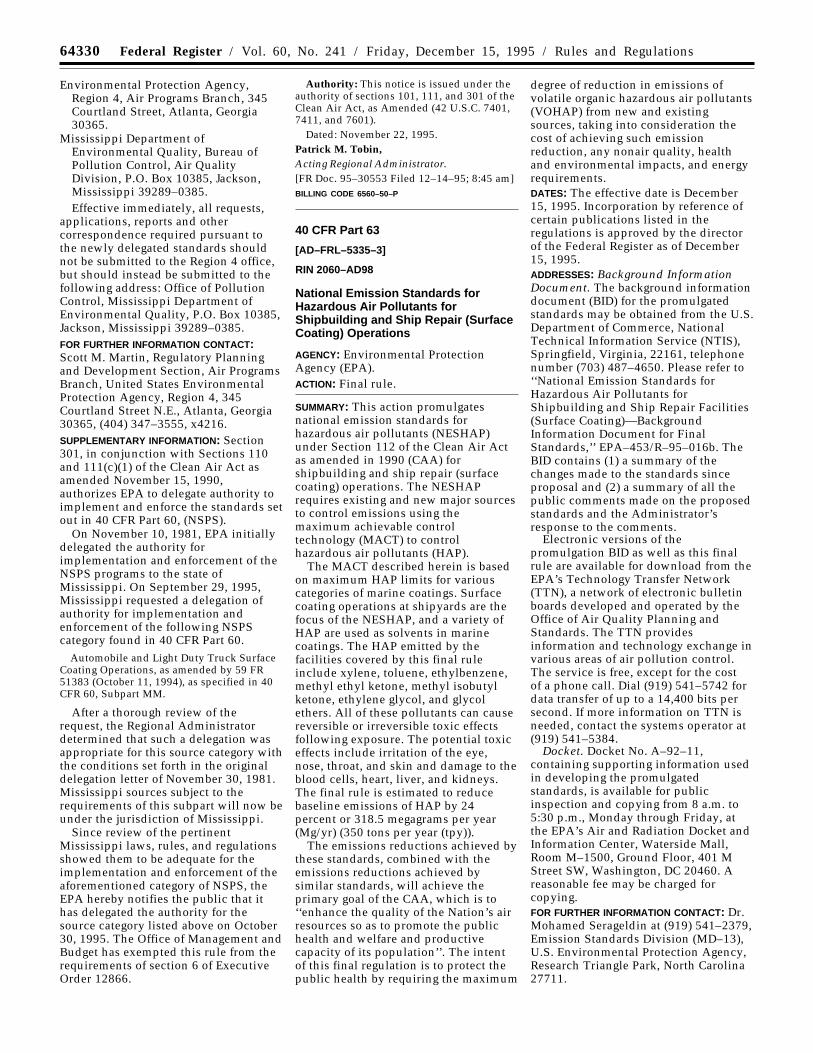
64330 Federal Register / Vol. 60, No. 241 / Friday, December 15, 1995 / Rules and Regulations
Environmental Protection Agency,Region 4, Air Programs Branch, 345Courtland Street, Atlanta, Georgia30365.
Mississippi Department ofEnvironmental Quality, Bureau ofPollution Control, Air QualityDivision, P.O. Box 10385, Jackson,Mississippi 39289–0385.Effective immediately, all requests,
applications, reports and othercorrespondence required pursuant tothe newly delegated standards shouldnot be submitted to the Region 4 office,but should instead be submitted to thefollowing address: Office of PollutionControl, Mississippi Department ofEnvironmental Quality, P.O. Box 10385,Jackson, Mississippi 39289–0385.FOR FURTHER INFORMATION CONTACT:Scott M. Martin, Regulatory Planningand Development Section, Air ProgramsBranch, United States EnvironmentalProtection Agency, Region 4, 345Courtland Street N.E., Atlanta, Georgia30365, (404) 347–3555, x4216.SUPPLEMENTARY INFORMATION: Section301, in conjunction with Sections 110and 111(c)(1) of the Clean Air Act asamended November 15, 1990,authorizes EPA to delegate authority toimplement and enforce the standards setout in 40 CFR Part 60, (NSPS).
On November 10, 1981, EPA initiallydelegated the authority forimplementation and enforcement of theNSPS programs to the state ofMississippi. On September 29, 1995,Mississippi requested a delegation ofauthority for implementation andenforcement of the following NSPScategory found in 40 CFR Part 60.
Automobile and Light Duty Truck SurfaceCoating Operations, as amended by 59 FR51383 (October 11, 1994), as specified in 40CFR 60, Subpart MM.
After a thorough review of therequest, the Regional Administratordetermined that such a delegation wasappropriate for this source category withthe conditions set forth in the originaldelegation letter of November 30, 1981.Mississippi sources subject to therequirements of this subpart will now beunder the jurisdiction of Mississippi.
Since review of the pertinentMississippi laws, rules, and regulationsshowed them to be adequate for theimplementation and enforcement of theaforementioned category of NSPS, theEPA hereby notifies the public that ithas delegated the authority for thesource category listed above on October30, 1995. The Office of Management andBudget has exempted this rule from therequirements of section 6 of ExecutiveOrder 12866.
Authority: This notice is issued under theauthority of sections 101, 111, and 301 of theClean Air Act, as Amended (42 U.S.C. 7401,7411, and 7601).
Dated: November 22, 1995.Patrick M. Tobin,Acting Regional Administrator.[FR Doc. 95–30553 Filed 12–14–95; 8:45 am]BILLING CODE 6560–50–P
40 CFR Part 63
[AD–FRL–5335–3]
RIN 2060–AD98
National Emission Standards forHazardous Air Pollutants forShipbuilding and Ship Repair (SurfaceCoating) Operations
AGENCY: Environmental ProtectionAgency (EPA).ACTION: Final rule.
SUMMARY: This action promulgatesnational emission standards forhazardous air pollutants (NESHAP)under Section 112 of the Clean Air Actas amended in 1990 (CAA) forshipbuilding and ship repair (surfacecoating) operations. The NESHAPrequires existing and new major sourcesto control emissions using themaximum achievable controltechnology (MACT) to controlhazardous air pollutants (HAP).
The MACT described herein is basedon maximum HAP limits for variouscategories of marine coatings. Surfacecoating operations at shipyards are thefocus of the NESHAP, and a variety ofHAP are used as solvents in marinecoatings. The HAP emitted by thefacilities covered by this final ruleinclude xylene, toluene, ethylbenzene,methyl ethyl ketone, methyl isobutylketone, ethylene glycol, and glycolethers. All of these pollutants can causereversible or irreversible toxic effectsfollowing exposure. The potential toxiceffects include irritation of the eye,nose, throat, and skin and damage to theblood cells, heart, liver, and kidneys.The final rule is estimated to reducebaseline emissions of HAP by 24percent or 318.5 megagrams per year(Mg/yr) (350 tons per year (tpy)).
The emissions reductions achieved bythese standards, combined with theemissions reductions achieved bysimilar standards, will achieve theprimary goal of the CAA, which is to‘‘enhance the quality of the Nation’s airresources so as to promote the publichealth and welfare and productivecapacity of its population’’. The intentof this final regulation is to protect thepublic health by requiring the maximum
degree of reduction in emissions ofvolatile organic hazardous air pollutants(VOHAP) from new and existingsources, taking into consideration thecost of achieving such emissionreduction, any nonair quality, healthand environmental impacts, and energyrequirements.DATES: The effective date is December15, 1995. Incorporation by reference ofcertain publications listed in theregulations is approved by the directorof the Federal Register as of December15, 1995.ADDRESSES: Background InformationDocument. The background informationdocument (BID) for the promulgatedstandards may be obtained from the U.S.Department of Commerce, NationalTechnical Information Service (NTIS),Springfield, Virginia, 22161, telephonenumber (703) 487–4650. Please refer to‘‘National Emission Standards forHazardous Air Pollutants forShipbuilding and Ship Repair Facilities(Surface Coating)—BackgroundInformation Document for FinalStandards,’’ EPA–453/R–95–016b. TheBID contains (1) a summary of thechanges made to the standards sinceproposal and (2) a summary of all thepublic comments made on the proposedstandards and the Administrator’sresponse to the comments.
Electronic versions of thepromulgation BID as well as this finalrule are available for download from theEPA’s Technology Transfer Network(TTN), a network of electronic bulletinboards developed and operated by theOffice of Air Quality Planning andStandards. The TTN providesinformation and technology exchange invarious areas of air pollution control.The service is free, except for the costof a phone call. Dial (919) 541–5742 fordata transfer of up to a 14,400 bits persecond. If more information on TTN isneeded, contact the systems operator at(919) 541–5384.
Docket. Docket No. A–92–11,containing supporting information usedin developing the promulgatedstandards, is available for publicinspection and copying from 8 a.m. to5:30 p.m., Monday through Friday, atthe EPA’s Air and Radiation Docket andInformation Center, Waterside Mall,Room M–1500, Ground Floor, 401 MStreet SW, Washington, DC 20460. Areasonable fee may be charged forcopying.FOR FURTHER INFORMATION CONTACT: Dr.Mohamed Serageldin at (919) 541–2379,Emission Standards Division (MD–13),U.S. Environmental Protection Agency,Research Triangle Park, North Carolina27711.
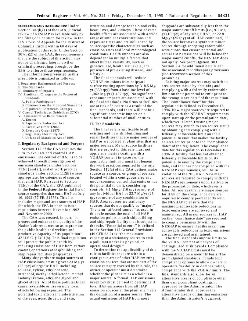
64331Federal Register / Vol. 60, No. 241 / Friday, December 15, 1995 / Rules and Regulations
SUPPLEMENTARY INFORMATION: UnderSection 307(b)(1) of the CAA, judicialreview of NESHAP is available only bythe filing of a petition for review in theU.S. Court of Appeals for the District ofColumbia Circuit within 60 days ofpublication of this rule. Under Section307(b)(2) of the CAA, the requirementsthat are the subject of this action maynot be challenged later in civil orcriminal proceedings brought by theEPA to enforce these requirements.
The information presented in thispreamble is organized as follows:I. Regulatory Background and PurposeII. The StandardsIII. Summary of ImpactsIV. Significant Changes to the Proposed
StandardsA. Public ParticipationB. Comments on the Proposed StandardsC. Significant Comments/Changes
V. Control Techniques Guidelines (CTG)VI. Administrative Requirements
A. DocketB. Paperwork Reduction ActC. Executive Order 12866D. Executive Order 12875E. Regulatory Flexibility ActF. Unfunded Mandates Act of 1995
I. Regulatory Background and PurposeSection 112 of the CAA requires the
EPA to evaluate and control HAPemissions. The control of HAP is to beachieved through promulgation ofemission standards under Sections112(d) and (f), and of work practicestandards under Section 112(h) whereappropriate, for categories of sourcesthat emit HAP. Pursuant to Section112(c) of the CAA, the EPA publishedin the Federal Register the initial list ofsource categories that emit HAP on July16, 1992 (57 FR. 31576). This listincludes major and area sources of HAPfor which the EPA intends to issueregulations between November 1992and November 2000.
The CAA was created, in part, ‘‘toprotect and enhance the quality of theNation’s air resources so as to promotethe public health and welfare andproductive capacity of its population’’42 U.S.C. § 7401(b). This final regulationwill protect the public health byreducing emissions of HAP from surfacecoating operations at shipbuilding andship repair facilities (shipyards).
Many shipyards are major sources ofHAP emissions, emitting over 23 Mg/yr(25 tpy) of organic HAP, includingtoluene, xylene, ethylbenzene,methanol, methyl ethyl ketone, methylisobutyl ketone, ethylene glycol andglycol ethers. All of these pollutants cancause reversible or irreversible toxiceffects following exposure. Thepotential toxic effects include irritationof the eyes, nose, throat, and skin,
irritation and damage to the blood cells,heart, liver, and kidneys. These adversehealth effects are associated with a widerange of ambient concentrations andexposure times and are influenced bysource-specific characteristics such asemission rates and local meteorologicalconditions. Health impacts are alsodependent on multiple factors thataffect human variability, such asgenetics, age, health status (e.g., thepresence of pre-existing disease), andlifestyle.
The final standards will reduceVOHAP emissions from shipyardsurface coating operations by 318.5 Mg/yr (350 tpy) from a baseline level of1,362 Mg/yr (1,497 tpy). No significanteconomic impacts are associated withthe final standards. No firms or facilitiesare at risk of closure as a result of thefinal standards, and there will not be asignificant economic impact on asubstantial number of small entities.
II. The StandardsThe final rule is applicable to all
existing and new shipbuilding andrepair facilities that are major sources ofHAP or are located at plant sites that aremajor sources. Major source facilitiesthat are subject to this rule must notapply any marine coating with aVOHAP content in excess of theapplicable limit and must implementthe work practices required in the rule.Section 112(a) of the CAA defines majorsource as a source, or group of sources,located within a contiguous area andunder common control that emits or hasthe potential to emit, consideringcontrols, 9.1 Mg/yr (10 tpy) or more ofany individual HAP or 22.7 Mg/yr (25tpy) or more of any combination ofHAP. Area sources are stationarysources that do not qualify as ‘‘major.’’The term ‘‘affected source’’ as used inthis rule means the total of all HAPemission points at each shipbuildingand ship repair facility that is subject tothe rule. ‘‘Potential to emit’’ is definedin the Section 112 General Provisions(40 CFR 63.2) as ‘‘the maximumcapacity of a stationary source to emita pollutant under its physical oroperational design.’’
To determine the applicability of thisrule to facilities that are within acontiguous area of other HAP-emittingemission sources that are not part of thesource category covered by this rule, theowner or operator must determinewhether the plant site as a whole is amajor source. A formal HAP emissionsinventory must be used to determine iftotal HAP emissions from all HAPemission sources at the plant site meetsthe definition of a major source. Theactual emissions of HAP from most
shipyards are substantially less than themajor source cutoff limits [i.e., 9.1 Mg/yr (10 tpy) of any single HAP, or 22.8Mg/yr (25 tpy) of all HAP combined]. Ifthe source becomes a synthetic minorsource through accepting enforceablerestrictions that ensure potential andactual HAP emissions will be below themajor source cutoffs, the NESHAP doesnot apply. See promulgation BIDSection 2.4 for additional details andthe associated recordkeeping provisions(see ADDRESSES section of thispreamble).
Existing major sources may switch toarea source status by obtaining andcomplying with a federally enforceablelimit on their potential to emit prior tothe ‘‘compliance date’’ of the regulation.The ‘‘compliance date’’ for thisregulation is defined as December 16,1996. New major sources are required tocomply with the NESHAP requirementsupon start up or the promulgation date,whichever is later. Existing majorsources may switch to area source statusby obtaining and complying with afederally enforceable limit on theirpotential to emit that makes the facilityan area source prior to the ‘‘compliancedate’’ of the regulation. The compliancedate for this regulation is December 16,1996. A facility that has not obtainedfederally enforceable limits on itspotential to emit by the compliancedate, and that has not complied with theNESHAP requirements, will be inviolation of the NESHAP. New majorsources are required to comply with theNESHAP requirements upon start-up orthe promulgation date, whichever islater. All sources that are major sourcesfor HAP on the compliance date arerequired to comply permanently withthe NESHAP to ensure that themaximum achievable reductions intoxic emissions are achieved andmaintained. All major sources for HAPon the ‘‘compliance date’’ are requiredto comply permanently with theNESHAP to ensure that the maximumachievable reductions in toxic emissionsare achieved and maintained.
The final standards impose limits onthe VOHAP content of 23 types ofcoatings used at shipyards. Compliancewith the VOHAP limits must bedemonstrated on a monthly basis. Thepromulgated standards include fourcompliance options to allow owners oroperators flexibility in demonstratingcompliance with the VOHAP limits. Thefinal standards also allow for analternative means of compliance otherthan using compliant coatings, ifapproved by the Administrator. TheAdministrator shall approve thealternative means of limiting emissionsif, in the Administrator’s judgment,
64332 Federal Register / Vol. 60, No. 241 / Friday, December 15, 1995 / Rules and Regulations
(after control) emissions of VOHAP pervolume solids applied will be no greaterthan those from the use of coatings thatcomply with the applicable VOHAPlimits.
The final standards also require thatall handling and transfer of VOHAPcontaining materials to and fromcontainers, tanks, vats, vessels, andpiping systems be conducted in amanner that minimizes spills and otherfactors leading to emissions. (Thisrequirement includes hand- or brush-application of coatings.) In addition,containers of thinning solvent or wastethat hold any VOHAP must be normallyclosed (to minimize evaporation) unlessmaterials are being added to or removedfrom them.
Owners or operators of existingshipbuilding and ship repair (surfacecoating) operations subject to therequirements promulgated underSection 112(d) of the CAA are requiredto comply with the standards within 1year from December 15, 1995. Ownersor operators of new shipbuilding andship repair (surface coating) operationswith initial startup before or afterDecember 15, 1996 are required tocomply with all requirements of thestandards upon startup. The firstrequirement is the initial notificationdue 6 months before start up.
III. Summary of ImpactsThese standards will reduce
nationwide emissions of HAP fromshipbuilding and ship repair (surfacecoating) operations by approximately318.5 Mg (350 tons) in 1997 comparedto the emissions that would result in theabsence of the standards. Thesestandards will also reduce volatileorganic compounds (VOC) emissionsfrom those same shipbuilding and shiprepair (surface coating) operations byapproximately 837 Mg (920 tons) in1997 compared to the emissions thatwould result in the absence of thestandards. No significant adversesecondary air, water, solid waste, orenergy impacts are anticipated from thepromulgation of these standards.
Implementation of this regulation isexpected to result in nationwideannualized costs for existing shipyardsof about $2 million beyond baseline.This estimation is based on an analysisof the application of VOHAP limits onmarine coatings at all existing majorsource facilities not currently controlledto the level of the standards.
The economic impact analysisconducted prior to proposal showedthat the economic impacts from theproposed standard would beinsignificant. An update of theeconomic impact analysis (due to
revisions to the final rule) indicates thatthe original conclusion still holds true.Implementation of the rule is notexpected to cause significant economicimpacts for the 35 major source facilitiesin this industry.
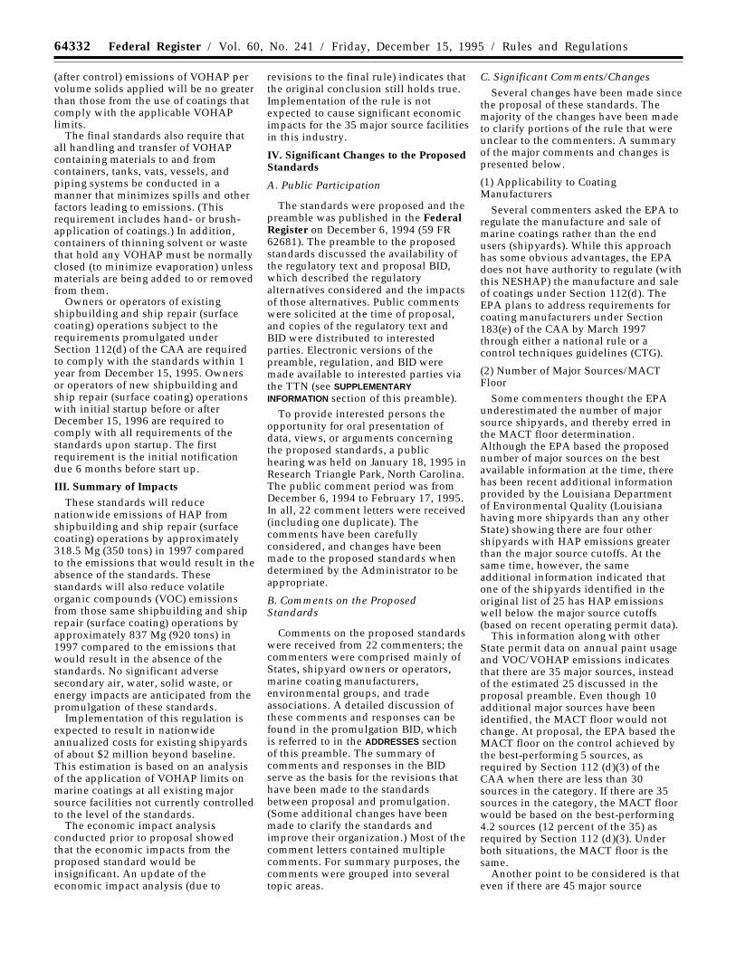
IV. Significant Changes to the ProposedStandards
A. Public Participation
The standards were proposed and thepreamble was published in the FederalRegister on December 6, 1994 (59 FR62681). The preamble to the proposedstandards discussed the availability ofthe regulatory text and proposal BID,which described the regulatoryalternatives considered and the impactsof those alternatives. Public commentswere solicited at the time of proposal,and copies of the regulatory text andBID were distributed to interestedparties. Electronic versions of thepreamble, regulation, and BID weremade available to interested parties viathe TTN (see SUPPLEMENTARYINFORMATION section of this preamble).
To provide interested persons theopportunity for oral presentation ofdata, views, or arguments concerningthe proposed standards, a publichearing was held on January 18, 1995 inResearch Triangle Park, North Carolina.The public comment period was fromDecember 6, 1994 to February 17, 1995.In all, 22 comment letters were received(including one duplicate). Thecomments have been carefullyconsidered, and changes have beenmade to the proposed standards whendetermined by the Administrator to beappropriate.
B. Comments on the ProposedStandards
Comments on the proposed standardswere received from 22 commenters; thecommenters were comprised mainly ofStates, shipyard owners or operators,marine coating manufacturers,environmental groups, and tradeassociations. A detailed discussion ofthese comments and responses can befound in the promulgation BID, whichis referred to in the ADDRESSES sectionof this preamble. The summary ofcomments and responses in the BIDserve as the basis for the revisions thathave been made to the standardsbetween proposal and promulgation.(Some additional changes have beenmade to clarify the standards andimprove their organization.) Most of thecomment letters contained multiplecomments. For summary purposes, thecomments were grouped into severaltopic areas.
C. Significant Comments/ChangesSeveral changes have been made since
the proposal of these standards. Themajority of the changes have been madeto clarify portions of the rule that wereunclear to the commenters. A summaryof the major comments and changes ispresented below.
(1) Applicability to CoatingManufacturers
Several commenters asked the EPA toregulate the manufacture and sale ofmarine coatings rather than the endusers (shipyards). While this approachhas some obvious advantages, the EPAdoes not have authority to regulate (withthis NESHAP) the manufacture and saleof coatings under Section 112(d). TheEPA plans to address requirements forcoating manufacturers under Section183(e) of the CAA by March 1997through either a national rule or acontrol techniques guidelines (CTG).
(2) Number of Major Sources/MACTFloor
Some commenters thought the EPAunderestimated the number of majorsource shipyards, and thereby erred inthe MACT floor determination.Although the EPA based the proposednumber of major sources on the bestavailable information at the time, therehas been recent additional informationprovided by the Louisiana Departmentof Environmental Quality (Louisianahaving more shipyards than any otherState) showing there are four othershipyards with HAP emissions greaterthan the major source cutoffs. At thesame time, however, the sameadditional information indicated thatone of the shipyards identified in theoriginal list of 25 has HAP emissionswell below the major source cutoffs(based on recent operating permit data).
This information along with otherState permit data on annual paint usageand VOC/VOHAP emissions indicatesthat there are 35 major sources, insteadof the estimated 25 discussed in theproposal preamble. Even though 10additional major sources have beenidentified, the MACT floor would notchange. At proposal, the EPA based theMACT floor on the control achieved bythe best-performing 5 sources, asrequired by Section 112 (d)(3) of theCAA when there are less than 30sources in the category. If there are 35sources in the category, the MACT floorwould be based on the best-performing4.2 sources (12 percent of the 35) asrequired by Section 112 (d)(3). Underboth situations, the MACT floor is thesame.
Another point to be considered is thateven if there are 45 major source
64333Federal Register / Vol. 60, No. 241 / Friday, December 15, 1995 / Rules and Regulations
shipyards, the best 12 percent is stillrepresented by the best 0.12 × 45 = 5.4or best 5 yards. Both the MACT floorand the associated marine coatingVOHAP limits would be identical. Sincethe NESHAP proposal date, the Navyhas adopted VOC limits identical to (ormore stringent than) the 1992 Californialimits for all Naval shipyards and Navy-related work. Since at least two of theNaval shipyards qualify as majorsources, if the MACT floor were to berecalculated today, the limits would beidentical to the proposed (andpromulgated) limits, regardless of theapproach used to determine the mean ormedian level of control. The Louisianalimits, which are less stringent for themajor use categories of coatings, wouldnot enter into any of the floorcalculations.
Recent indications from the Navy andother industry representatives revealthat fewer affected sources exist todaybecause of base closings andconsolidation efforts. The originalestimation of 25 major source shipyardswas based on annual paint and solventusage, type of work conducted (newconstruction versus repair), number ofemployees, and type (size) of vesselsserviced. The (weighted) average HAPconcentration of all marine coatings isan integral part of emissions estimatesand determining if a shipyard qualifiesas a major source facility. Other HAP-emitting processes at most shipyardssuch as welding, metal forming/cutting,and abrasive blasting exist, but the vastmajority of HAP emissions come fromorganic solvents used in marine paintsand solvents used for thinning andcleaning.
(3) Elimination of Compliance Option 1Proposed compliance option 1
required that each and every containerof coating be tested or certified prior toapplication. Based on commentspertaining to its impracticality and theunrealistic costs associated with testing/certifying every container of coating,compliance option 1 was eliminatedfrom the final rule. The flow diagram(included as Figure 1 in the regulation)summarizing the various complianceoptions was similarly revised andsimplified.
(4) Training RequirementsIn the proposed rule, the EPA
required training and certification for allpersonnel involved with paints and/orsolvents. There were several commentsregarding the inappropriate amount andlevel of detail involved with the trainingand annual personnel certifications.Some commenters indicated that therewas a high turnover rate involving
personnel, and the proposed trainingrequirements would impose asignificant impact for very littlereduction in HAP emissions. The EPAhas determined that it is appropriate toleave the details of training to theindividual shipyards who can bestdefine the real needs of their specificlocations and applications. Affectedsources are responsible for complyingwith the standards, and it is in theirown best interest to ensure that workersare aware of the associatedrequirements. Therefore, all trainingrequirements related to painting/thinning, handling/transfer of VOHAP-containing materials, and certification ofall personnel involved with surfacecoating operations have been eliminatedfrom the final rule.
(5) Definition of Pleasure CraftA definition of pleasure craft has been
added to ensure that the standardsapply only to those coatings (andsolvents) used on commercial andmilitary vessels. Some commenters wereconcerned that, as proposed, the rulecould be interpreted to regulate coatingsused on pleasure crafts. Othercommenters suggested that pleasurecrafts should be included. The EPA didnot intend to include coatings used onpleasure crafts in these standards. Suchcoatings (applications) will beconsidered under the development ofthe Boat Manufacturing NESHAP.
(6) Definition of Affected SourceThe definition of affected source was
modified to ensure that therequirements of the standards applyonly to those sources (major sourceshipyards) with a minimum annualmarine coating usage of 1,000 L (264.2gal). The primary focus of this NESHAPis surface coating operations and thisclarification will minimize/eliminatethe impact on shipyards with minimalsurface coating emissions.
(7) Reporting and Notification ChangesChanges have also been made to the
notification and reporting schedules.The initial notification deadline hasbeen extended from 120 to 180 days.The frequency of reporting has also beenreduced from the proposed quarterlyrequirement to semiannual. This changewas made to allow shipyards to beconsistent with current/upcoming TitleV permit requirements. The firstcompliance certification report is due 6months after the compliance date.
(8) ExemptionsSeveral commenters recommended
that the EPA adopt some of theexemptions provided in various State
regulations. Since the MACT floor wasbased on three shipyards located inCalifornia and those yards haveexemptions similar to those requested,the EPA determined there would be nosignificant impact and adopted thefollowing exemptions:
a. Any individual coating with annualusage less than 200 liters (52.8 gallons)is exempt from the requirements of thestandards (i.e., the applicable VOHAPlimit). The total amount of all coatingsexempted in any given year cannotexceed 1,000 liters (264.2 gallons); and
b. Any coating applied vianonrefillable hand-held aerosol cans isexempt from the requirements of thestandards.
(9) Revision of EquationsThe equations used with compliance
options 2 and 3 (proposed options 3 and4) have been changed so thatcalculations are based on volume solids.The revised equations require theVOHAP limits based on volume solidsbe used in place of the VOHAP limitsbased on volume of coating less waterand non-HAP exempt solvents. Thischange was made to provide a uniformbasis for calculating emissionreductions (i.e., associated withthinning additions or add-on controldevices).
(10) Weather-related VOHAP limitsThe proposal preamble requested
comments on how to handle thinningissues for various climatic conditions.The EPA reviewed the comments andcollected additional information on bothcold-and hot/humid-weather thinningpractices. As a result of thisinformation, cold-weather VOHAPlimits are included as part of the finalrule. If the temperature is below 4.5°C(40°F) at the time the coating is appliedand the source needs to thin that coatingbeyond the applicable VOHAP limit, thedate, time, and temperature (includingunits) must be documented, and theapplicable cold-weather VOHAP limitmay be used. The cold-weather VOHAPlimits on a solids basis were increasedequivalently, but the actual values varyfor each coating category. The cold-weather VOHAP limits are applicableonly to as-supplied coatings that aregreater than 40 percent solids byvolume.
With regards to hot/humid weatherconditions, the data and responses toSection 114 information requests sentby EPA to nine shipyards and otherinformation received did not provide abasis for including a humid weatherthinning allowance. Respondentsidentified meteorological conditionsunder which coatings must be thinned
64334 Federal Register / Vol. 60, No. 241 / Friday, December 15, 1995 / Rules and Regulations
or not applied at all. Only one shipyard,which uses large quantities of water-based preconstruction primer,maintained that a humid weatherthinning allowance should be adopted.However, the shipyard did not explainhow hydrocarbon-based thinners wouldrelate to its water-based operation.
Hot and humid weather conditionsappear to inhibit coating operationswork less frequently than does coldweather. The different responses canbest be understood as they relate to thespecifications for thinning underdifferent climatic conditions, which aredependent on paint type andmanufacturer. Some coatingformulations lose at high temperaturemore organic solvent than others whichcould lead to thickening (increase inviscosity) of the paint. This occurswhere the rate of application is low andpaint containers remain uncovered.Nevertheless, beginning in September1994, shipyards performing work for theNavy in humid climates such asLouisiana, Florida, and Virginia arerequired by the Navy to use paints withVOHAP contents levels that are incompliance with the limits in theNESHAP, without provision foradditional thinning. There is no reasonthat VOHAP limits that are achievablefor paints used by the Navy cannot alsobe achieved for paints used bycommercial shipyards located in humidclimates and that, therefore, a thinningallowance for hot/humid weatherconditions is not necessary. Ifconditions necessitate application ofsmall amount of noncompliant coatings,the regulation provides a low usageexemption of 1,000 liters of coating peryear.
D. Minor Changes
This section contains a list of severalof the minor changes to the final rule.A discussion of these changes can befound in the promulgation BID. (SeeADDRESSES section of this preamble.)
(1) Revisions to definitions andphrasing have been made to clarify theregulation.
(2) Based on comments received andon changes to the notification andrecordkeeping and reportingrequirements, those sections of thestandard have been reorganized andoverlapping requirements clarified oreliminated.
(3) Table 2, which contains theVOHAP limits for the various coatingcategories, has been simplified tocontain only one set of units (metric).The conversion factor for English unitsis included as a footnote to the table.
V. Control Techniques Guidelines(CTG)
Section 183(b)(4) of the CAA requiresthe Administrator to issue a CTGdocument for limiting VOC andparticulate matter emissions fromcoatings (paints) and solvents used inthe shipbuilding and ship repairindustry. Since VOHAP emissions fromthis industry are generally a subset ofVOC emissions, the control techniquesevaluated for the MACT standard arealso applicable to VOC emissions.Therefore, the EPA has developed theCTG concurrently with the NESHAPand will be issuing final guidance undera separate notice. As explained in theproposal notice (AD–FR– ), no CTGis being issued for particulate matteremissions.
VI. Administrative Requirements
A. DocketThe Docket is an organized and
complete file of all the informationconsidered by the EPA in thedevelopment of this rulemaking. TheDocket is a dynamic file, since materialis added throughout the rulemakingdevelopment. The docketing system isintended to allow members of the publicand industries involved to readilyidentify and locate documents so thatthey can effectively participate in therulemaking process. Along with thestatement of basis and purpose of theproposed and promulgated standardsand the EPA responses to significantcomments, the contents of the Docketwill serve as the record in case ofjudicial review [see 42 U.S.C.7607(d)(7)(A)].
B. Paperwork Reduction ActThe Office of Management and Budget
(OMB) is currently reviewing theinformation collection request (ICR)requirements contained in this ruleunder the provisions of the PaperworkReduction Act, 44 U.S.C. 3501 et seq.and has assigned OMB control number2060–0330 and EPA ICR number 1712.2.
The information required to becollected by this rule is needed as partof the overall compliance andenforcement program. It is necessary toidentify the regulated entities who aresubject to the rule and to ensure theircompliance with the rule. Therecordkeeping and reportingrequirements are mandatory and arebeing established under authority ofSection 114 of the Act. All informationsubmitted to the EPA for which a claimof confidentiality is made will besafeguarded according to the EPApolicies set forth in Title 40, Chapter 1,Part 2, Subpart B—Confidentiality of
Information (see 40 CFR part 2; 41 FR36902, September 1, 1976; amended by43 FR 39999, September 8, 1978; 43 FR42251, September 28, 1978; 44 FR17674, March 23, 1979).
The total annual reporting andrecordkeeping burden for this collectionaveraged over the first 3 years isestimated to be $26,218 per year. Theaverage burden, per respondent, is 772hours per year. This estimate includesthe time needed to review instructions;develop, acquire, install, and utilizetechnology and systems for the purposesof collecting, validating, and verifyinginformation, processing andmaintaining information, and disclosingand providing information; adjust theexisting ways to comply with anypreviously applicable instructions andrequirements; train personnel to be ableto respond to a collection ofinformation; search data sources;complete and review the collection ofinformation; and transmit or otherwisedisclose the information. The total time,effort, or financial resources expendedby persons to generate, maintain, retain,or disclose or provide information to orfor a Federal agency. This includes thetime needed to review instructions;develop, acquire, install, and utilizetechnology and systems for the purposesof collecting, validating, and verifyinginformation, processing andmaintaining information, and disclosingand providing information; adjust theexisting ways to comply with anypreviously applicable instructions andrequirements; train personnel to be ableto respond to a collection ofinformation; search data sources;complete and review the collection ofinformation; and transmit or otherwisedisclose the information. The rulerequires an initial one-time notificationfrom each respondent and subsequentnotification every 6 months to indicatetheir compliance status. At the time ofthe initial notification each respondentwould also be required to submit animplementation plan that describescompliance procedures. A respondentwould also be required to keepnecessary records of data to determinecompliance with the standards in theregulation. The data would be recordedmonthly. A report would need to besubmitted semi-annually by eachrespondent. There would be anestimated 35 respondents to theproposed collection requirements.
Send comments on the EPA’s need forthis information, the accuracy of theprovided burden estimates, and anysuggested methods for minimizingrespondent burden, including throughthe use of automated collectiontechniques to the Director, OPPE
64335Federal Register / Vol. 60, No. 241 / Friday, December 15, 1995 / Rules and Regulations
Regulatory Information Division; U. S.Environmental Protection Agency(2136); 401 M Street SW.; Washington,DC 20460; and to the Office ofInformation and Regulatory Affairs,Office of Management and Budget, 72517th Street NW.; Washington, DC 20503;marked ‘‘Attention: Desk Officer forEPA.’’ Include the OMB number and theEPA ICR number in anycorrespondence.
C. Executive Order 12866:Administrative Designation andRegulatory Analysis
Under Executive Order 12866 [58 FR51735 (October 4, 1993)], the EPA isrequired to judge whether a regulationis ‘‘significant’’ and therefore subject toOMB review and the requirements ofthis Executive Order to prepare aregulatory impact analysis (RIA). TheOrder defines ‘‘significant regulatoryaction’’ as one that is likely to result ina rule that may (1) have an annual effecton the economy of $100 million or moreor adversely affect in a material way theeconomy, a sector of the economy,productivity, competition, jobs, theenvironment, public health or safety, orState, local, or tribal governments orcommunities; (2) create a seriousinconsistency or otherwise interferewith an action taken or planned byanother agency; (3) materially alter thebudgetary impact of entitlements,grants, user fees, or loan programs, orthe rights and obligation of recipientsthereof; or (4) raise novel legal or policyissues arising out of legal mandates, thePresident’s priorities, or the principlesset forth in the Executive Order.
Pursuant to the terms of ExecutiveOrder 12866, it has been determinedthat this rule is not a ‘‘significantregulatory action’’ and is therefore notsubject to OMB review.
D. Executive Order 12875To reduce the burden of federal
regulations on States and smallgovernments, the President issuedExecutive Order 12875 on October 26,1993, entitled Enhancing theIntergovernmental Partnership. Inparticular, this executive order isdesigned to require agencies to assessthe effects of regulations that are notrequired by statute and that createmandates upon State, local, or tribalgovernments. Two methods exist forcomplying with the requirements of theexecutive order: (1) Assure that fundsnecessary to pay direct costs ofcompliance with a regulation areprovided, or (2) provide OMB adescription of the communications andconsultations with State/local/tribalgovernments, the nature of their
concerns, any written submission fromthem, and the EPA’s position supportingthe need to issue the regulation.
The EPA has always been concernedabout the effect of the cost of regulationson small entities; the EPA has consultedwith and sought input from publicentities to explain costs and burdensthey may incur.
The EPA advised interested parties onJuly 16, 1992 (57 FR 21592), of thecategories considered as major and areasources of HAP, and shipbuilding andship repair (surface coating) industrywas listed as a category of both majorand area sources. The EPA madesignificant effort to hear from all levelsof interest and all segments of theshipbuilding and ship repair industry.To facilitate comments and input, theEPA conducted comprehensive mailoutsof draft and proposal package materialsin 1993 and 1994 to shipyards,Department of the Navy (Naval SeaSystems Command), marine coatingmanufacturers, and State and localgovernment officials. All were givenopportunity to comment on thepresented regulatory developmentactivities of the standard. Throughoutthe regulatory development process andmore specifically in consultationmeetings, industry representatives fromcommercial/private shipyards, the U.S.Navy, and various trade associationswere given an opportunity to commenton the proposed regulatory approachand the MACT alternatives beingdeveloped. The major topic areasresulting from these discussionsincluded the need for cold-weatherthinning limits, flexibility incompliance approaches, and the needfor additional data regarding certaincoating categories (i.e., inorganic zincs).Some of these meetings were held atEPA, while others were conducted atshipyard locations. In addition,individual consultations wereconducted with three local (air qualitymanagement) districts in Californiaregarding the use of the mass ofVOHAP/volume of solids fordetermining compliance when thecoating is thinned.
The EPA addressed many of thesuggestions and comments receivedfrom State and local agencies during thepublic comment period, many of whichwill reduce the impact to smallbusinesses. Some of these suggestionsresulted in changes to the rule,including modification of the definitionof pleasure craft to clarify that thestandards apply only to coatings (andsolvents) used on commercial andmilitary vessels and not to boats in non-military shipyards less than 20 metersin length; modification of the definition
of affected source to ensure that therequirements of the standards applyonly to those sources (major sourceshipyards) with a minimum annualmarine coating usage of 1,000 Liters(264.2 gallons); exemption of anyindividual coating with annual usageless than 200 liters (52.8 gallons) (i.e.,the applicable VOHAP limit);exemption of any coating applied vianonrefillable hand-held aerosol cans;making the equations used to determinethinning allowance the same for alloptions to provide a uniform basis forcalculating emission reductions (i.e.,associated with thinning additions oradd-on control devices); extension ofthe initial notification deadline from120 to 180 days and reduction of thefrequency of reporting from theproposed quarterly requirement tosemiannual, which allows shipyards tobe consistent with current/upcomingTitle V permit requirements;reorganization and clarification of thenotification and recordkeeping andreporting requirement, includingrevision of the definitions and phrasingto ensure that the terminology isunderstandable; and the addition of 10major sources based on data providedby Louisiana and Texas State agencies.
Some of the other major concerns thatwere noted in the State and/or localagency comments and that wereconsidered by the EPA in developingthe proposed and final rule involvedrealistic work practice standards,multiple compliance options to provideflexibility for shipyard owners/operatorsand State regulators, and streamlining(or eliminating) any overlappingrecordkeeping and reportingrequirements. Documentation of allmeetings and public comments can befound in Docket A–92–11.
The EPA has considered the purposeand intent of Executive Order 12875 andhas determined that shipbuilding andship repair facility NESHAP are needed.The rule is generally required by statuteunder Section 112 of the CAA becauseshipbuilding and ship repair facilitiesemit significant quantities of airpollutants. Through meetings andconsultations during projectdevelopment and proposal, efforts weremade to inform entities of the costsrequired to comply with the regulation;in addition, modifications were made toreduce the burden to small entities.
E. Regulatory Flexibility ActThe Regulatory Flexibility Act (5
U.S.C. 601 et seq.) requires the EPA toconsider potential impacts of proposedregulations on small business ‘‘entities.’’If a preliminary analysis indicates thata proposed regulation would have a
64336 Federal Register / Vol. 60, No. 241 / Friday, December 15, 1995 / Rules and Regulations
significant economic impact on 20percent or more of small entities, thena regulatory flexibility analysis must beprepared. The EPA’s analysis of theseimpacts was provided in the preambleto the proposed rule (59 FR 62681) andno negative impacts for small businesseswill result from the changesincorporated into the final rule.
Pursuant to the provisions of 5 U.S.C.605(b), I hereby certify that this rule willnot have a significant economic impacton a substantial number of smallbusiness entities.
F. Unfunded Mandates Act of 1995Title II of the Unfunded Mandates
Reform Act of 1995 (UMRA), PublicLaw 104–4, establishes requirements forFederal agencies to assess the effects oftheir regulatory actions on State, local,and tribal governments and the privatesector. Under Section 202 of the UMRA,the EPA generally must prepare awritten statement including a cost-benefit analysis, for proposed and finalrules with ‘‘Federal mandates’’ that mayresult in expenditures to State, local,and tribal governments, in the aggregate,or to the private sector, of $100 millionor more in any 1 year. Beforepromulgating an EPA rule for which awritten statement is needed, Section 205of the UMRA generally requires EPA toidentify and consider a reasonablenumber of regulatory alternatives andadopt the least costly, most cost-effective or least burdensome alternativethat achieves the objectives of the rule.The provisions of Section 205 do notapply when they are inconsistent withapplicable law. Moreover, Section 205allows EPA to adopt an alternative otherthan the least costly, most cost-effectiveor least burdensome alternative if theAdministrator publishes with the finalrule an explanation why that alternativewas not adopted. Before EPA establishesany regulatory requirements that maysignificantly or uniquely affect smallgovernments, including tribalgovernments, it must have developedunder Section 203 of the UMRA a smallgovernment agency plan. The plan mustprovide for notifying potentiallyaffected small governments, enablingofficials of affected small governmentsto have meaningful and timely input inthe development of EPA regulatoryproposals with significant Federalintergovernmental mandates andinforming, educating, and advisingsmall governments on compliance withthe regulatory requirements.
The EPA has determined that theaction promulgated today does notinclude a Federal mandate that mayresult in estimated costs of $100 millionor more to either State, local, or tribal
governments in the aggregate, or to theprivate sector. Therefore, therequirements of the Unfunded MandatesAct do not apply to this action.
List of Subjects in 40 CFR Part 63Environmental protection, Air
pollution control, Incorporation byreference, Marine coating limits,Reporting and recordkeepingrequirements, Shipbuilding and shiprepair standards.
Dated: November 14, 1995.Carol M. Browner,Administrator.
For the reasons set out in thepreamble, title 40, chapter I, part 63 ofthe Code of Federal Regulations isamended as follows:
PART 63—NATIONAL EMISSIONSTANDARDS FOR HAZARDOUS AIRPOLLUTANTS FOR SHIPBUILDINGAND SHIP REPAIR (SURFACECOATING)
1. The authority citation for part 63continues to read as follows:
Authority: Sections 101, 112, 114, 116, and301 of the Clean Air Act (42 U.S.C. 7401 etseq., as amended by Pub. L. 101–549, 104Stat. 2399).
2. Section 63.14 is amended byadding paragraph (b)(4) through (b)(14)to read as follows:
§ 63.14 Incorporation by reference.
* * * * *(b) * * *(4) ASTM D523–89, Standard Test
Method for Specular Gloss, IBRapproved for § 63.782.
(5) ASTM D1475–90, Standard TestMethod for Density of Paint, Varnish,Lacquer, and Related Products, IBRapproved for § 63.788 appendix A.
(6) ASTM D2369–93, Standard TestMethod for Volatile Content of Coatings,IBR approved for § 63.788 appendix A.
(7) ASTM D3912–80, Standard TestMethod for Chemical Resistance ofCoatings Used in Light-Water NuclearPower Plants, IBR approved for§ 63.782.
(8) ASTM D4017–90, Standard TestMethod for Water and Paints and PaintMaterials by Karl Fischer Method, IBRapproved for § 63.788 appendix A.
(9) ASTM D4082–89, Standard TestMethod for Effects of Gamma Radiationon Coatings for Use in Light-WaterNuclear Power Plants, IBR approved for§ 63.782.
(10) ASTM D4256–89 [reapproved1994], Standard Test Method forDetermination of the Decontaminabilityof Coatings Used in Light-Water NuclearPower Plants, IBR approved for§ 63.782.
(11) ASTM D3792–91, Standard TestMethod for Water Content of Water-Reducible Paints by Direct Injection intoa Gas Chromatograph, IBR approved for§ 63.788 appendix A.
(12) ASTM D3257–93, Standard TestMethods for Aromatics in MineralSpirits by Gas Chromatography, IBRapproved for § 63.786(b).
(13) ASTM E260–91, StandardPractice for Packed Column GasChromatography, IBR approved for§ 63.786(b).
(14) ASTM E180–93, StandardPractice for Determining the Precision ofASTM Methods for Analysis andTesting of Industrial Chemicals, IBRapproved for § 63.786(b).
3. Part 63 is amended by addingsubpart II to read as follows:
Subpart II—National EmissionStandards for Shipbuilding and ShipRepair (Surface Coating)
Secs.63.780 Relationship of subpart II to subpart
A of this part.63.781 Applicability.63.782 Definitions.63.783 Standards.63.784 Compliance dates.63.785 Compliance procedures.63.786 Test methods and procedures.63.787 Notification requirements.63.788 Recordkeeping and reporting
requirements.Table 1 to Subpart II of Part 63—General
Provisions of Applicability to Subpart IITable 2 to Subpart II of Part 63—Volatile
Organic HAP (VOHAP) Limits for MarineCoatings
Table 3 to Subpart II of Part 63—Summaryof Recordkeeping and ReportingRequirements
Appendix A to Subpart II of Part 63—VOCData Sheet
Appendix B to Subpart II of Part 63—Maximum Allowable Thinning Rates Asa Function of As Supplied VOC Contentand Thinner Density
Subpart II—National EmissionStandards for Shipbuilding and ShipRepair (Surface Coating)
§ 63.780 Relationship of subpart II tosubpart A of this part.
Table 1 of this subpart specifies theprovisions of subpart A of this part thatapply to owners and operators ofsources subject to the provisions of thissubpart.
§ 63.781 Applicability.(a) The provisions of this subpart
apply to shipbuilding and ship repairoperations at any facility that is a majorsource.
(b) The provisions of this subpart donot apply to coatings used in volumesof less than 200 liters (52.8 gallons) per
64337Federal Register / Vol. 60, No. 241 / Friday, December 15, 1995 / Rules and Regulations
year, provided the total volume ofcoating exempt under this paragraphdoes not exceed 1,000 liters per year(264 gallons per year) at any facility.Coatings exempt under this paragraphshall be clearly labeled as ‘‘low-usageexempt,’’ and the volume of each suchcoating applied shall be maintained inthe facility’s records.
(c) The provisions of this subpart donot apply to coatings applied withhand-held, nonrefillable, aerosolcontainers or to unsaturated polyesterresin (i.e., fiberglass lay-up) coatings.Coatings applied to suitably preparedfiberglass surfaces for protective ordecorative purposes are subject to thissubpart.
(d) The provisions in subpart A of thispart pertaining to startups, shutdowns,and malfunctions and continuousmonitoring do not apply to this sourcecategory unless an add-on controlsystem is used to comply with thissubpart in accordance with § 63.783(c).
§ 63.782 Definitions.Terms used in this subpart are
defined in the Clean Air Act (CAA), insubpart A of part 63, or in this sectionas follows:
Add-on control system means an airpollution control device such as acarbon absorber or incinerator thatreduces pollution in an air stream bydestruction or removal prior todischarge to the atmosphere.
Affected source means anyshipbuilding or ship repair facilityhaving surface coating operations with aminimum 1,000 liters (L) (264 gallons[gal]) annual marine coating usage thatis subject to this subpart.
Air flask specialty coating means anyspecial composition coating applied tointerior surfaces of high pressurebreathing air flasks to provide corrosionresistance and that is certified safe foruse with breathing air supplies.
Antenna specialty coating means anycoating applied to equipment throughwhich electromagnetic signals mustpass for reception or transmission.
Antifoulant specialty coating meansany coating that is applied to theunderwater portion of a vessel toprevent or reduce the attachment ofbiological organisms and that isregistered with the EPA as a pesticideunder the Federal Insecticide,Fungicide, and Rodenticide Act.
As applied means the condition of acoating at the time of application to thesubstrate, including any thinningsolvent.
As supplied means the condition of acoating before any thinning, as sold anddelivered by the coating manufacturer tothe user.
Batch means the product of anindividual production run of a coatingmanufacturer’s process. A batch mayvary in composition from other batchesof the same product.
Bitumens mean black or brownmaterials that are soluble in carbondisulfide and consist mainly ofhydrocarbons.
Bituminous resin coating means anycoating that incorporates bitumens as aprincipal component and is formulatedprimarily to be applied to a substrate orsurface to resist ultraviolet radiationand/or water.
Certify means, in reference to thevolatile organic compounds (VOC)content or volatile organic hazardous airpollutants (VOHAP) content of acoating, to attest to the VOC content asdetermined through analysis by Method24 of appendix A to 40 CFR part 60 orthrough use of forms and proceduresoutlined in appendix A of this subpart,or to attest to the VOHAP content asdetermined through an Administrator-approved test method. In the case ofconflicting results, Method 24 ofAppendix A to 40 CFR part 60 shall takeprecedence over the forms andprocedures outlined in appendix A tothis subpart for the options in whichVOC is used as a surrogate for VOHAP.
Coating means any material that canbe applied as a thin layer to a substrateand which cures to form a continuoussolid film.
Cold-weather time period means anytime during which the ambienttemperature is below 4.5°C (40°F) andcoating is to be applied.
Container of coating means thecontainer from which the coating isapplied, including but not limited to abucket or pot.
Cure volatiles means reactionproducts which are emitted during thechemical reaction which takes place insome coating films at the curetemperature. These emissions are otherthan those from the solvents in thecoating and may, in some cases,comprise a significant portion of totalVOC and/or VOHAP emissions.
Epoxy means any thermoset coatingformed by reaction of an epoxy resin(i.e., a resin containing a reactiveepoxide with a curing agent).
Exempt compounds means specifiedorganic compounds that are notconsidered VOC due to negligiblephotochemical reactivity. Exemptcompounds are specified in 40 CFR51.100(s).
Facility means all contiguous oradjoining property that is undercommon ownership or control,including properties that are separated
only by a road or other public right-of-way.
General use coating means anycoating that is not a specialty coating.
Hazardous air pollutants (HAP)means any air pollutant listed in orpursuant to section 112(b) of the CAA.
Heat resistant specialty coating meansany coating that during normal use mustwithstand a temperature of at least204°C (400°F).
High-gloss specialty coating meansany coating that achieves at least 85percent reflectance on a 60 degree meterwhen tested by ASTM Method D523(incorporation by reference—see§ 63.14).
High-temperature specialty coatingmeans any coating that during normaluse must withstand a temperature of atleast 426°C (800°F).
Inorganic zinc (high-build) specialtycoating means a coating that contains960 grams per liter (8 pounds pergallon) or more elemental zincincorporated into an inorganic silicatebinder that is applied to steel to providegalvanic corrosion resistance. (Thesecoatings are typically applied at morethan 2 mil dry film thickness.)
Major source means any source thatemits or has the potential to emit, in theaggregate, 9.1 megagrams per year (10tons per year) or more of any HAP or22.7 megagrams per year (25 tons peryear) or more of any combination ofHAP.
Maximum allowable thinning ratiomeans the maximum volume of thinnerthat can be added per volume of coatingwithout violating the standards of§ 63.783(a), as determined usingEquation 1 of this subpart.
Military exterior specialty coating orChemical Agent Resistant Coatings(‘‘CARC’’) means any exterior topcoatapplied to military or U.S. Coast Guardvessels that are subject to specificchemical, biological, and radiologicalwashdown requirements.
Mist specialty coating means any lowviscosity, thin film, epoxy coatingapplied to an inorganic zinc primer thatpenetrates the porous zinc primer andallows the occluded air to escapethrough the paint film prior to curing.
Navigational aids specialty coatingmeans any coating applied to CoastGuard buoys or other Coast Guardwaterway markers when they arerecoated aboard ship at their usage siteand immediately returned to the water.
Nonskid specialty coating means anycoating applied to the horizontalsurfaces of a marine vessel for thespecific purpose of providing slipresistance for personnel, vehicles, oraircraft.
64338 Federal Register / Vol. 60, No. 241 / Friday, December 15, 1995 / Rules and Regulations
Nonvolatiles (or volume solids) meanssubstances that do not evaporatereadily. This term refers to the film-forming material of a coating.
Normally closed means a container orpiping system is closed unless anoperator is actively engaged in adding orremoving material.
Nuclear specialty coating means anyprotective coating used to seal poroussurfaces such as steel (or concrete) thatotherwise would be subject to intrusionby radioactive materials. These coatingsmust be resistant to long-term (servicelife) cumulative radiation exposure(ASTM D4082–89 [incorporation byreference—see § 63.14]), relatively easyto decontaminate (ASTM D4256–89[reapproved 1994] [incorporation byreference—see § 63.14]), and resistant tovarious chemicals to which the coatingsare likely to be exposed (ASTM D3912–80 [incorporation by reference—see§ 63.14]). [For nuclear coatings, see thegeneral protective requirementsoutlined by the U.S. Nuclear RegulatoryCommission in a report entitled ‘‘U.S.Atomic Energy Commission RegulatoryGuide 1.54’’ dated June 1973, availablethrough the Government Printing Officeat (202) 512–2249 as document numberA74062–00001.]
Operating parameter value means aminimum or maximum valueestablished for a control device orprocess parameter that, if achieved byitself or in combination with one ormore other operating parameter values,determines that an owner or operatorhas complied with an applicableemission limitation or standard.
Organic zinc specialty coating meansany coating derived from zinc dustincorporated into an organic binder thatcontains more than 960 grams ofelemental zinc per liter (8 pounds pergallon) of coating, as applied, and thatis used for the expressed purpose ofcorrosion protection.
Pleasure craft means any marine orfresh-water vessel used by individualsfor noncommercial, nonmilitary, andrecreational purposes that is less than20 meters in length. A vessel rentedexclusively to or chartered byindividuals for such purposes shall beconsidered a pleasure craft.
Pretreatment wash primer specialtycoating means any coating that containsa minimum of 0.5 percent acid, by mass,and is applied only to bare metal to etchthe surface and enhance adhesion ofsubsequent coatings.
Repair and maintenance ofthermoplastic coating of commercialvessels (specialty coating) means anyvinyl, chlorinated rubber, or bituminousresin coating that is applied over thesame type of existing coating to perform
the partial recoating of any in-usecommercial vessel. (This definition doesnot include coal tar epoxy coatings,which are considered ‘‘general use’’coatings.)
Rubber camouflage specialty coatingmeans any specially formulated epoxycoating used as a camouflage topcoat forexterior submarine hulls and sonardomes. Sealant for thermal sprayaluminum means any epoxy coatingapplied to thermal spray aluminumsurfaces at a maximum thickness of 1dry mil.
Ship means any marine or fresh-watervessel used for military or commercialoperations, including self-propelledvessels, those propelled by other craft(barges), and navigational aids (buoys).This definition includes, but is notlimited to, all military and Coast Guardvessels, commercial cargo and passenger(cruise) ships, ferries, barges, tankers,container ships, patrol and pilot boats,and dredges. For purposes of thissubpart, pleasure crafts and offshore oiland gas drilling platforms are notconsidered ships.
Shipbuilding and ship repairoperations means any building, repair,repainting, converting, or alteration ofships.
Special marking specialty coatingmeans any coating that is used for safetyor identification applications, such asmarkings on flight decks and ships’numbers.
Specialty coating means any coatingthat is manufactured and used for oneof the specialized applicationsdescribed within this list of definitions.
Specialty interior coating means anycoating used on interior surfaces aboardU.S. military vessels pursuant to acoating specification that requires thecoating to meet specified fire retardantand low toxicity requirements, inaddition to the other applicable militaryphysical and performance requirements.
Tack specialty coating means any thinfilm epoxy coating applied at amaximum thickness of 2 dry mils toprepare an epoxy coating that has driedbeyond the time limit specified by themanufacturer for the application of thenext coat.
Thinner means a liquid that is used toreduce the viscosity of a coating andthat evaporates before or during the cureof a film.
Thinning ratio means the volumetricratio of thinner to coating, as supplied.
Thinning solvent: see Thinner.Undersea weapons systems specialty
coating means any coating applied toany component of a weapons systemintended to be launched or fired fromunder the sea.
Volatile organic compounds (VOC) isas defined in § 51.100(s) of this chapter.
Volatile organic hazardous airpollutants (VOHAP) means anycompound listed in or pursuant tosection 112(b) of the CAA that containscarbon, excluding metallic carbides andcarbonates. This definition includesVOC listed as HAP and exemptcompounds listed as HAP.
Weld-through preconstruction primer(specialty coating) means a coating thatprovides corrosion protection for steelduring inventory, is typically applied atless than 1 mil dry film thickness, doesnot require removal prior to welding, istemperature resistant (burn back from aweld is less than 1.25 centimeters [0.5inch]), and does not normally requireremoval before applying film-buildingcoatings, including inorganic zinc high-build coatings. When constructing newvessels, there may be a need to removeareas of weld-through preconstructionprimer due to surface damage orcontamination prior to application offilm-building coatings.
§ 63.783 Standards.(a) No owner or operator of any
existing or new affected source shallcause or allow the application of anycoating to a ship with an as-appliedVOHAP content exceeding theapplicable limit given in Table 2 of thissubpart, as determined by theprocedures described in § 63.785 (c)(1)through (c)(4). For the complianceprocedures described in § 63.785 (c)(1)through (c)(3), VOC shall be used as asurrogate for VOHAP, and Method 24 ofAppendix A to 40 CFR part 60 shall beused as the definitive measure fordetermining compliance. For thecompliance procedure described in§ 63.785(c)(4), an alternative test methodcapable of measuring independentVOHAP shall be used to determinecompliance. The method must besubmitted to and approved by theAdministrator.
(b) Each owner or operator of a newor existing affected source shall ensurethat:
(1) All handling and transfer ofVOHAP-containing materials to andfrom containers, tanks, vats, drums, andpiping systems is conducted in amanner that minimizes spills.
(2) All containers, tanks, vats, drums,and piping systems are free of cracks,holes, and other defects and remainclosed unless materials are being addedto or removed from them.
(c) Approval of alternative means oflimiting emissions. (1) The owner oroperator of an affected source may applyto the Administrator for permission touse an alternative means (such as an
64339Federal Register / Vol. 60, No. 241 / Friday, December 15, 1995 / Rules and Regulations
add-on control system) of limitingemissions from coating operations. Theapplication must include:
(i) An engineering material balanceevaluation that provides a comparisonof the emissions that would be achievedusing the alternative means to those thatwould result from using coatings thatcomply with the limits in Table 2 of thissubpart, or the results from an emissiontest that accurately measures the captureefficiency and control device efficiencyachieved by the control system and thecomposition of the associated coatingsso that the emissions comparison can bemade;
(ii) A proposed monitoring protocolthat includes operating parametervalues to be monitored for complianceand an explanation of how the operatingparameter values will be establishedthrough a performance test; and
(iii) Details of appropriaterecordkeeping and reportingprocedures.
(2) The Administrator shall approvethe alternative means of limitingemissions if, in the Administrator’sjudgment, postcontrol emissions ofVOHAP per volume applied solids willbe no greater than those from the use ofcoatings that comply with the limits inTable 2 of this subpart.
(3) The Administrator may conditionapproval on operation, maintenance,and monitoring requirements to ensurethat emissions from the source are nogreater than those that would otherwiseresult from this subpart. § 63.784Compliance dates.
(a) Each owner or operator of anexisting affected source shall complywithin 1 year after the effective date ofthis subpart.
(b) Each owner or operator of anexisting unaffected area source thatincreases its emissions of (or itspotential to emit) HAP such that thesource becomes a major source that issubject to this subpart shall complywithin 1 year after the date of becominga major source.
(c) Each owner or operator of a newor reconstructed source shall complywith this subpart according to theschedule in § 63.6(b).
§ 63.785 Compliance procedures.(a) For each batch of coating that is
received by an affected source, theowner or operator shall (see Figure 1 ofthis section for a flow diagram of thecompliance procedures):
(1) Determine the coating categoryand the applicable VOHAP limit asspecified in § 63.783(a).
(2) Certify the as-supplied VOCcontent of the batch of coating. Theowner or operator may use a
certification supplied by themanufacturer for the batch, although theowner or operator retains liabilityshould subsequent testing reveal aviolation. If the owner or operatorperforms the certification testing, onlyone of the containers in which the batchof coating was received is required to betested.
(b)(1) In lieu of testing each batch ofcoating, as applied, the owner oroperator may determine compliancewith the VOHAP limits using anycombination of the proceduresdescribed in paragraphs (c)(1), (c)(2),(c)(3), and (c)(4) of this section. Theprocedure used for each coating shall bedetermined and documented prior toapplication.
(2) The results of any compliancedemonstration conducted by theaffected source or any regulatory agencyusing Method 24 shall take precedenceover the results using the procedures inparagraphs (c)(1), (c)(2), or (c)(3) of thissection.
(3) The results of any compliancedemonstration conducted by theaffected source or any regulatory agencyusing an approved test method todetermine VOHAP content shall takeprecedence over the results using theprocedures in paragraph (c)(4) of thissection.
(c)(1) Coatings to which thinningsolvent will not be added. For coatingsto which thinning solvent (or any othermaterial) will not be added under anycircumstance or to which only water isadded, the owner or operator of anaffected source shall comply as follows:
(i) Certify the as-applied VOC contentof each batch of coating.
(ii) Notify the persons responsible forapplying the coating that no thinningsolvent may be added to the coating byaffixing a label to each container ofcoating in the batch or through anothermeans described in the implementationplan required in § 63.787(b).
(iii) If the certified as-applied VOCcontent of each batch of coating usedduring a calendar month is less than orequal to the applicable VOHAP limit in§ 63.783(a) (either in terms of g/L ofcoating or g/L of solids), thencompliance is demonstrated for thatcalendar month, unless a violation isrevealed using Method 24 of AppendixA to 40 CFR part 60.
(2) Coatings to which thinning solventwill be added—coating-by-coatingcompliance. For a coating to whichthinning solvent is routinely orsometimes added, the owner or operatorshall comply as follows:
(i) Prior to the first application of eachbatch, designate a single thinner for thecoating and calculate the maximum
allowable thinning ratio (or ratios, if theaffected source complies with the cold-weather limits in addition to the otherlimits specified in Table 2 of thissubpart) for each batch as follows:
RV m
Ds VOC
th
=( )( ) −VOHAP limit
Eqn. 1
where:R=Maximum allowable thinning ratio
for a given batch (L thinner/Lcoating as supplied);
Vs=Volume fraction of solids in thebatch as supplied (L solids/Lcoating as supplied);
VOHAP limit=Maximum allowable as-applied VOHAP content of thecoating (g VOHAP/L solids);
mVOC=VOC content of the batch assupplied [g VOC (including curevolatiles and exempt compounds onthe HAP list)/L coating (includingwater and exempt compounds) assupplied];
Dth=Density of the thinner (g/L).If Vs is not supplied directly by the
coating manufacturer, the owner oroperator shall determine Vs as follows:
Vm
Dsvolatiles
avg
= −1 Eqn. 2
where:mvolatiles=Total volatiles in the batch,
including VOC, water, and exemptcompounds (g/L coating); and
Davg=Average density of volatiles in thebatch (g/L).
The procedures specified in§ 63.786(d) may be used to determinethe values of variables defined in thisparagraph. In addition, the owner oroperator may choose to constructnomographs, based on Equation 1 of thissubpart, similar or identical to the oneprovided in appendix B of this subpartas a means of easily estimating themaximum allowable thinning ratio.
(ii) Prior to the first application ofeach batch, notify painters and otherpersons, as necessary, of the designatedthinner and maximum allowablethinning ratio(s) for each batch of thecoating by affixing a label to eachcontainer of coating or through anothermeans described in the implementationplan required in § 63.787(b).
(iii) By the 15th day of each calendarmonth, determine the volume of eachbatch of the coating used, as supplied,during the previous month.
(iv) By the 15th day of each calendarmonth, determine the total allowablevolume of thinner for the coating usedduring the previous month as follows:
64340 Federal Register / Vol. 60, No. 241 / Friday, December 15, 1995 / Rules and Regulations
V R V R Vth b i cold b cold ii
n
i
n
= ×( ) + ×( )−==∑∑
11
Eqn. 3
where:Vth=Total allowable volume of thinner
for the previous month (L thinner);Vb=Volume of each batch, as supplied
and before being thinned, usedduring non-cold-weather days ofthe previous month (L coating assupplied);
Rcold=Maximum allowable thinning ratiofor each batch used during cold-weather days (L thinner/L coatingas supplied);
Vb-cold=Volume of each batch, assupplied and before being thinned,used during cold-weather days ofthe previous month (L coating assupplied);
i=Each batch of coating; andn=Total number of batches of the
coating.(v) By the 15th day of each calendar
month, determine the volume of thinneractually used with the coating duringthe previous month.
(vi) If the volume of thinner actuallyused with the coating [paragraph(c)(3)(v) of this section] is less than orequal to the total allowable volume ofthinner for the coating [paragraph(c)(3)(iv) of this section], thencompliance is demonstrated for thecoating for the previous month, unlessa violation is revealed using Method 24of Appendix A to 40 CFR part 60.
(3) Coatings to which the samethinning solvent will be added—groupcompliance. For coatings to which thesame thinning solvent (or othermaterial) is routinely or sometimesadded, the owner or operator shallcomply as follows:
(i) Designate a single thinner to beadded to each coating during the month
and ‘‘group’’ coatings according to theirdesignated thinner.
(ii) Prior to the first application ofeach batch, calculate the maximumallowable thinning ratio (or ratios, if theaffected source complies with the cold-weather limits in addition to the otherlimits specified in Table 2 of thissubpart) for each batch of coating in thegroup using the equations in paragraph(c)(2) of this section.
(iii) Prior to the first application ofeach ‘‘batch,’’ notify painters and otherpersons, as necessary, of the designatedthinner and maximum allowablethinning ratio(s) for each batch in thegroup by affixing a label to eachcontainer of coating or through anothermeans described in the implementationplan required in § 63.787(b).
(iv) By the 15th day of each calendarmonth, determine the volume of eachbatch of the group used, as supplied,during the previous month.
(v) By the 15th day of each calendarmonth, determine the total allowablevolume of thinner for the group for theprevious month using Equation 3 of thissubpart.
(vi) By the 15th day of each calendarmonth, determine the volume of thinneractually used with the group during theprevious month.
(vii) If the volume of thinner actuallyused with the group [paragraph (c)(3)(vi)of this section] is less than or equal tothe total allowable volume of thinner forthe group [paragraph (c)(3)(v) of thissection], then compliance isdemonstrated for the group for theprevious month, unless a violation isrevealed using Method 24 of AppendixA to 40 CFR part 60.
(4) Demonstration of compliancethrough an alternative (i.e., other thanMethod 24 of Appendix A to 40 CFRpart 60) test method. The owner oroperator shall comply as follows:
(i) Certify the as-supplied VOHAPcontent (g VOHAP/L solids) of eachbatch of coating.
(ii) If no thinning solvent will beadded to the coating, the owner oroperator of an affected source shallfollow the procedure described in§ 63.785(c)(1), except that VOHAPcontent shall be used in lieu of VOCcontent.
(iii) If thinning solvent will be addedto the coating, the owner or operator ofan affected source shall follow theprocedure described in § 63.785(c)(2) or(3), except that in Equation 1 of thissubpart: the term ‘‘mVOC’’ shall bereplaced by the term ‘‘mVOHAP,’’ definedas the VOHAP content of the coating assupplied (g VOHAP/L coating) and theterm ‘‘Dth’’ shall be replaced by the term‘‘Dth(VOHAP)’’ defined as the averagedensity of the VOHAP thinner(s) (g/L).
(d) A violation revealed through anyapproved test method shall result in a1-day violation for enforcementpurposes. A violation revealed throughthe recordkeeping procedures describedin paragraphs (c)(1) through (c)(4) of thissection shall result in a 30-day violationfor enforcement purposes, unless theowner or operator provides sufficientdata to demonstrate the specific daysduring which noncompliant coatingswere applied.
BILLING CODE 6560–50–P
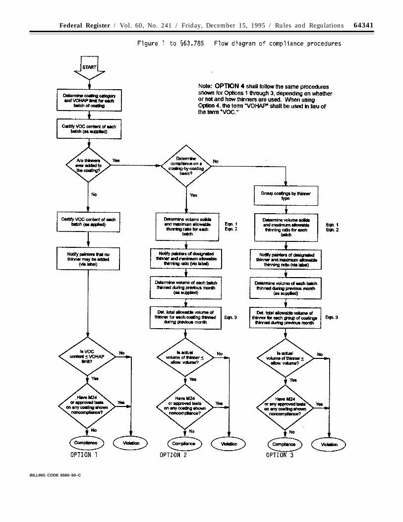
64341Federal Register / Vol. 60, No. 241 / Friday, December 15, 1995 / Rules and Regulations
BILLING CODE 6560–50–C
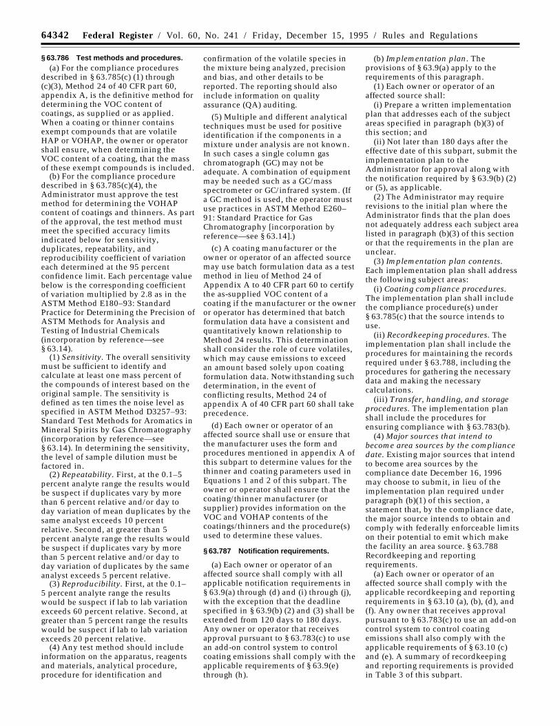
64342 Federal Register / Vol. 60, No. 241 / Friday, December 15, 1995 / Rules and Regulations
§ 63.786 Test methods and procedures.(a) For the compliance procedures
described in § 63.785(c) (1) through(c)(3), Method 24 of 40 CFR part 60,appendix A, is the definitive method fordetermining the VOC content ofcoatings, as supplied or as applied.When a coating or thinner containsexempt compounds that are volatileHAP or VOHAP, the owner or operatorshall ensure, when determining theVOC content of a coating, that the massof these exempt compounds is included.
(b) For the compliance proceduredescribed in § 63.785(c)(4), theAdministrator must approve the testmethod for determining the VOHAPcontent of coatings and thinners. As partof the approval, the test method mustmeet the specified accuracy limitsindicated below for sensitivity,duplicates, repeatability, andreproducibility coefficient of variationeach determined at the 95 percentconfidence limit. Each percentage valuebelow is the corresponding coefficientof variation multiplied by 2.8 as in theASTM Method E180–93: StandardPractice for Determining the Precision ofASTM Methods for Analysis andTesting of Industrial Chemicals(incorporation by reference—see§ 63.14).
(1) Sensitivity. The overall sensitivitymust be sufficient to identify andcalculate at least one mass percent ofthe compounds of interest based on theoriginal sample. The sensitivity isdefined as ten times the noise level asspecified in ASTM Method D3257–93:Standard Test Methods for Aromatics inMineral Spirits by Gas Chromatography(incorporation by reference—see§ 63.14). In determining the sensitivity,the level of sample dilution must befactored in.
(2) Repeatability. First, at the 0.1–5percent analyte range the results wouldbe suspect if duplicates vary by morethan 6 percent relative and/or day today variation of mean duplicates by thesame analyst exceeds 10 percentrelative. Second, at greater than 5percent analyte range the results wouldbe suspect if duplicates vary by morethan 5 percent relative and/or day today variation of duplicates by the sameanalyst exceeds 5 percent relative.
(3) Reproducibility. First, at the 0.1–5 percent analyte range the resultswould be suspect if lab to lab variationexceeds 60 percent relative. Second, atgreater than 5 percent range the resultswould be suspect if lab to lab variationexceeds 20 percent relative.
(4) Any test method should includeinformation on the apparatus, reagentsand materials, analytical procedure,procedure for identification and
confirmation of the volatile species inthe mixture being analyzed, precisionand bias, and other details to bereported. The reporting should alsoinclude information on qualityassurance (QA) auditing.
(5) Multiple and different analyticaltechniques must be used for positiveidentification if the components in amixture under analysis are not known.In such cases a single column gaschromatograph (GC) may not beadequate. A combination of equipmentmay be needed such as a GC/massspectrometer or GC/infrared system. (Ifa GC method is used, the operator mustuse practices in ASTM Method E260–91: Standard Practice for GasChromatography [incorporation byreference—see § 63.14].)
(c) A coating manufacturer or theowner or operator of an affected sourcemay use batch formulation data as a testmethod in lieu of Method 24 ofAppendix A to 40 CFR part 60 to certifythe as-supplied VOC content of acoating if the manufacturer or the owneror operator has determined that batchformulation data have a consistent andquantitatively known relationship toMethod 24 results. This determinationshall consider the role of cure volatiles,which may cause emissions to exceedan amount based solely upon coatingformulation data. Notwithstanding suchdetermination, in the event ofconflicting results, Method 24 ofappendix A of 40 CFR part 60 shall takeprecedence.
(d) Each owner or operator of anaffected source shall use or ensure thatthe manufacturer uses the form andprocedures mentioned in appendix A ofthis subpart to determine values for thethinner and coating parameters used inEquations 1 and 2 of this subpart. Theowner or operator shall ensure that thecoating/thinner manufacturer (orsupplier) provides information on theVOC and VOHAP contents of thecoatings/thinners and the procedure(s)used to determine these values.
§ 63.787 Notification requirements.
(a) Each owner or operator of anaffected source shall comply with allapplicable notification requirements in§ 63.9(a) through (d) and (i) through (j),with the exception that the deadlinespecified in § 63.9(b) (2) and (3) shall beextended from 120 days to 180 days.Any owner or operator that receivesapproval pursuant to § 63.783(c) to usean add-on control system to controlcoating emissions shall comply with theapplicable requirements of § 63.9(e)through (h).
(b) Implementation plan. Theprovisions of § 63.9(a) apply to therequirements of this paragraph.
(1) Each owner or operator of anaffected source shall:
(i) Prepare a written implementationplan that addresses each of the subjectareas specified in paragraph (b)(3) ofthis section; and
(ii) Not later than 180 days after theeffective date of this subpart, submit theimplementation plan to theAdministrator for approval along withthe notification required by § 63.9(b) (2)or (5), as applicable.
(2) The Administrator may requirerevisions to the initial plan where theAdministrator finds that the plan doesnot adequately address each subject arealisted in paragraph (b)(3) of this sectionor that the requirements in the plan areunclear.
(3) Implementation plan contents.Each implementation plan shall addressthe following subject areas:
(i) Coating compliance procedures.The implementation plan shall includethe compliance procedure(s) under§ 63.785(c) that the source intends touse.
(ii) Recordkeeping procedures. Theimplementation plan shall include theprocedures for maintaining the recordsrequired under § 63.788, including theprocedures for gathering the necessarydata and making the necessarycalculations.
(iii) Transfer, handling, and storageprocedures. The implementation planshall include the procedures forensuring compliance with § 63.783(b).
(4) Major sources that intend tobecome area sources by the compliancedate. Existing major sources that intendto become area sources by thecompliance date December 16, 1996may choose to submit, in lieu of theimplementation plan required underparagraph (b)(1) of this section, astatement that, by the compliance date,the major source intends to obtain andcomply with federally enforceable limitson their potential to emit which makethe facility an area source. § 63.788Recordkeeping and reportingrequirements.
(a) Each owner or operator of anaffected source shall comply with theapplicable recordkeeping and reportingrequirements in § 63.10 (a), (b), (d), and(f). Any owner that receives approvalpursuant to § 63.783(c) to use an add-oncontrol system to control coatingemissions shall also comply with theapplicable requirements of § 63.10 (c)and (e). A summary of recordkeepingand reporting requirements is providedin Table 3 of this subpart.
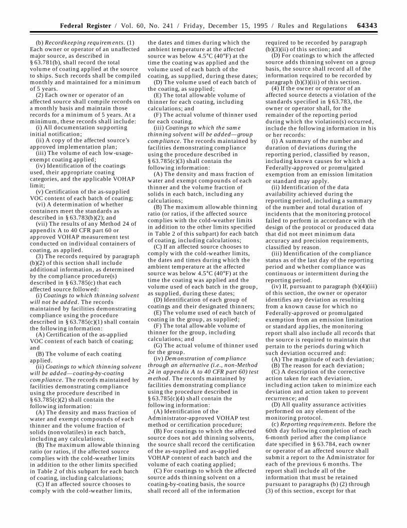
64343Federal Register / Vol. 60, No. 241 / Friday, December 15, 1995 / Rules and Regulations
(b) Recordkeeping requirements. (1)Each owner or operator of an unaffectedmajor source, as described in§ 63.781(b), shall record the totalvolume of coating applied at the sourceto ships. Such records shall be compiledmonthly and maintained for a minimumof 5 years.
(2) Each owner or operator of anaffected source shall compile records ona monthly basis and maintain thoserecords for a minimum of 5 years. At aminimum, these records shall include:
(i) All documentation supportinginitial notification;
(ii) A copy of the affected source’sapproved implementation plan;
(iii) The volume of each low-usage-exempt coating applied;
(iv) Identification of the coatingsused, their appropriate coatingcategories, and the applicable VOHAPlimit;
(v) Certification of the as-suppliedVOC content of each batch of coating;
(vi) A determination of whethercontainers meet the standards asdescribed in § 63.783(b)(2); and
(vii) The results of any Method 24 ofappendix A to 40 CFR part 60 orapproved VOHAP measurement testconducted on individual containers ofcoating, as applied.
(3) The records required by paragraph(b)(2) of this section shall includeadditional information, as determinedby the compliance procedure(s)described in § 63.785(c) that eachaffected source followed:
(i) Coatings to which thinning solventwill not be added. The recordsmaintained by facilities demonstratingcompliance using the proceduredescribed in § 63.785(c)(1) shall containthe following information:
(A) Certification of the as-appliedVOC content of each batch of coating;and
(B) The volume of each coatingapplied.
(ii) Coatings to which thinning solventwill be added—coating-by-coatingcompliance. The records maintained byfacilities demonstrating complianceusing the procedure described in§ 63.785(c)(2) shall contain thefollowing information:
(A) The density and mass fraction ofwater and exempt compounds of eachthinner and the volume fraction ofsolids (nonvolatiles) in each batch,including any calculations;
(B) The maximum allowable thinningratio (or ratios, if the affected sourcecomplies with the cold-weather limitsin addition to the other limits specifiedin Table 2 of this subpart for each batchof coating, including calculations;
(C) If an affected source chooses tocomply with the cold-weather limits,
the dates and times during which theambient temperature at the affectedsource was below 4.5°C (40°F) at thetime the coating was applied and thevolume used of each batch of thecoating, as supplied, during these dates;
(D) The volume used of each batch ofthe coating, as supplied;
(E) The total allowable volume ofthinner for each coating, includingcalculations; and
(F) The actual volume of thinner usedfor each coating.
(iii) Coatings to which the samethinning solvent will be added—groupcompliance. The records maintained byfacilities demonstrating complianceusing the procedure described in§ 63.785(c)(3) shall contain thefollowing information:
(A) The density and mass fraction ofwater and exempt compounds of eachthinner and the volume fraction ofsolids in each batch, including anycalculations;
(B) The maximum allowable thinningratio (or ratios, if the affected sourcecomplies with the cold-weather limitsin addition to the other limits specifiedin Table 2 of this subpart) for each batchof coating, including calculations;
(C) If an affected source chooses tocomply with the cold-weather limits,the dates and times during which theambient temperature at the affectedsource was below 4.5°C (40°F) at thetime the coating was applied and thevolume used of each batch in the group,as supplied, during these dates;
(D) Identification of each group ofcoatings and their designated thinners;
(E) The volume used of each batch ofcoating in the group, as supplied;
(F) The total allowable volume ofthinner for the group, includingcalculations; and
(G) The actual volume of thinner usedfor the group.
(iv) Demonstration of compliancethrough an alternative (i.e., non-Method24 in appendix A to 40 CFR part 60) testmethod. The records maintained byfacilities demonstrating complianceusing the procedure described in§ 63.785(c)(4) shall contain thefollowing information:
(A) Identification of theAdministrator-approved VOHAP testmethod or certification procedure;
(B) For coatings to which the affectedsource does not add thinning solvents,the source shall record the certificationof the as-supplied and as-appliedVOHAP content of each batch and thevolume of each coating applied;
(C) For coatings to which the affectedsource adds thinning solvent on acoating-by-coating basis, the sourceshall record all of the information
required to be recorded by paragraph(b)(3)(ii) of this section; and
(D) For coatings to which the affectedsource adds thinning solvent on a groupbasis, the source shall record all of theinformation required to be recorded byparagraph (b)(3)(iii) of this section.
(4) If the owner or operator of anaffected source detects a violation of thestandards specified in § 63.783, theowner or operator shall, for theremainder of the reporting periodduring which the violation(s) occurred,include the following information in hisor her records:
(i) A summary of the number andduration of deviations during thereporting period, classified by reason,including known causes for which aFederally-approved or promulgatedexemption from an emission limitationor standard may apply.
(ii) Identification of the dataavailability achieved during thereporting period, including a summaryof the number and total duration ofincidents that the monitoring protocolfailed to perform in accordance with thedesign of the protocol or produced datathat did not meet minimum dataaccuracy and precision requirements,classified by reason.
(iii) Identification of the compliancestatus as of the last day of the reportingperiod and whether compliance wascontinuous or intermittent during thereporting period.
(iv) If, pursuant to paragraph (b)(4)(iii)of this section, the owner or operatoridentifies any deviation as resultingfrom a known cause for which noFederally-approved or promulgatedexemption from an emission limitationor standard applies, the monitoringreport shall also include all records thatthe source is required to maintain thatpertain to the periods during whichsuch deviation occurred and:
(A) The magnitude of each deviation;(B) The reason for each deviation;(C) A description of the corrective
action taken for each deviation,including action taken to minimize eachdeviation and action taken to preventrecurrence; and
(D) All quality assurance activitiesperformed on any element of themonitoring protocol.
(c) Reporting requirements. Before the60th day following completion of each6-month period after the compliancedate specified in § 63.784, each owneror operator of an affected source shallsubmit a report to the Administrator foreach of the previous 6 months. Thereport shall include all of theinformation that must be retainedpursuant to paragraphs (b) (2) through(3) of this section, except for that
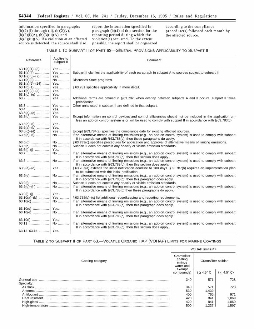
64344 Federal Register / Vol. 60, No. 241 / Friday, December 15, 1995 / Rules and Regulations
information specified in paragraphs(b)(2) (i) through (ii), (b)(2)(v),(b)(3)(i)(A), (b)(3)(ii)(A), and(b)(3)(iii)(A). If a violation at an affectedsource is detected, the source shall also
report the information specified inparagraph (b)(4) of this section for thereporting period during which theviolation(s) occurred. To the extentpossible, the report shall be organized
according to the complianceprocedure(s) followed each month bythe affected source.
TABLE 1 TO SUBPART II OF PART 63—GENERAL PROVISIONS APPLICABILITY TO SUBPART II
Reference Applies tosubpart II Comment
63.1(a)(1)–(3) ......... Yes. .........63.1(a)(4) ............... Yes .......... Subpart II clarifies the applicability of each paragraph in subpart A to sources subject to subpart II.63.1(a)(5)–(7) ......... Yes.63.1(a)(8) ............... No ............ Discusses State programs.63.1(a)(9)–(14) ....... Yes.63.1(b)(1) ............... Yes .......... § 63.781 specifies applicability in more detail.63.1(b)(2)–(3) ......... Yes.63.1(c)–(e) ............. Yes.63.2 ........................ Yes .......... Additional terms are defined in § 63.782; when overlap between subparts A and II occurs, subpart II takes
precedence.63.3 ........................ Yes .......... Other units used in subpart II are defined in that subpart.63.4 ........................ Yes.63.5(a)–(c) ............. Yes.63.5(d) ................... Yes .......... Except information on control devices and control efficiencies should not be included in the application un-
less an add-on control system is or will be used to comply with subpart II in accordance with § 63.783(c).63.5(e)–(f) .............. Yes.63.6(a)–(b) ............. Yes.63.6(c)–(d) ............. Yes .......... Except § 63.784(a) specifies the compliance date for existing affected sources.63.6(e)–(f) .............. No ............ If an alternative means of limiting emissions (e.g., an add-on control system) is used to comply with subpart
II in accordance with § 63.783(c), then these paragraphs do apply.63.6(g) ................... No ............ § 63.783(c) specifies procedures for application and approval of alternative means of limiting emissions.63.6(h) ................... No ............ Subpart II does not contain any opacity or visible emission standards.63.6(i)–(j) ............... Yes.63.7 ........................ No ............ If an alternative means of limiting emissions (e.g., an add-on control system) is used to comply with subpart
II in accordance with § 63.783(c), then this section does apply.63.8 ........................ No ............ If an alternative means of limiting emissions (e.g., an add-on control system) is used to comply with subpart
II in accordance with § 63.783(c), then this section does apply.63.9(a)–(d) ............. Yes .......... § 63.787(a) extends the initial notification deadline to 180 days. § 63.787(b) requires an implementation plan
to be submitted with the initial notification.63.9(e) ................... No ............ If an alternative means of limiting emissions (e.g., an add-on control system) is used to comply with subpart
II in accordance with § 63.783(c), then this paragraph does apply.63.9(f) .................... No ............ Subpart II does not contain any opacity or visible emission standards63.9(g)–(h) ............. No ............ If an alternative means of limiting emissions (e.g., an add-on control system) is used to comply with subpart
II in accordance with § 63.783(c) then these paragraphs do apply.63.9(i)–(j) ............... Yes.63.10(a)–(b) ........... Yes .......... § 63.788(b)–(c) list additional recordkeeping and reporting requirements.63.10(c) .................. No ............ If an alternative means of limiting emissions (e.g., an add-on control system) is used to comply with subpart
II in accordance with § 63.783(c), then this paragraph does apply.63.10(d) ................. Yes.63.10(e) ................. No ............ If an alternative means of limiting emissions (e.g., an add-on control system) is used to comply with subpart
II in accordance with § 63.783(c), then this paragraph does apply.63.10(f) .................. Yes.63.11 ...................... No ............ If an alternative means of limiting emissions (e.g., an add-on control system) is used to comply with subpart
II in accordance with § 63.783(c), then this section does apply.63.12–63.15 ........... Yes.
TABLE 2 TO SUBPART II OF PART 63.—VOLATILE ORGANIC HAP (VOHAP) LIMITS FOR MARINE COATINGS
Coating category
VOHAP limits a b c
Grams/litercoating(minus
water andexempt
compounds)
Grams/liter solids d
t ≥ 4.5° C t < 4.5° C e
General use ............................................................................................................................................. 340 571 728Specialty:
Air flask ................................................................................................................................................. 340 571 728Antenna ................................................................................................................................................ 530 1,439Antifoulant ............................................................................................................................................. 400 765 971Heat resistant ....................................................................................................................................... 420 841 1,069High-gloss ............................................................................................................................................. 420 841 1,069High-temperature .................................................................................................................................. 500 1,237 1,597
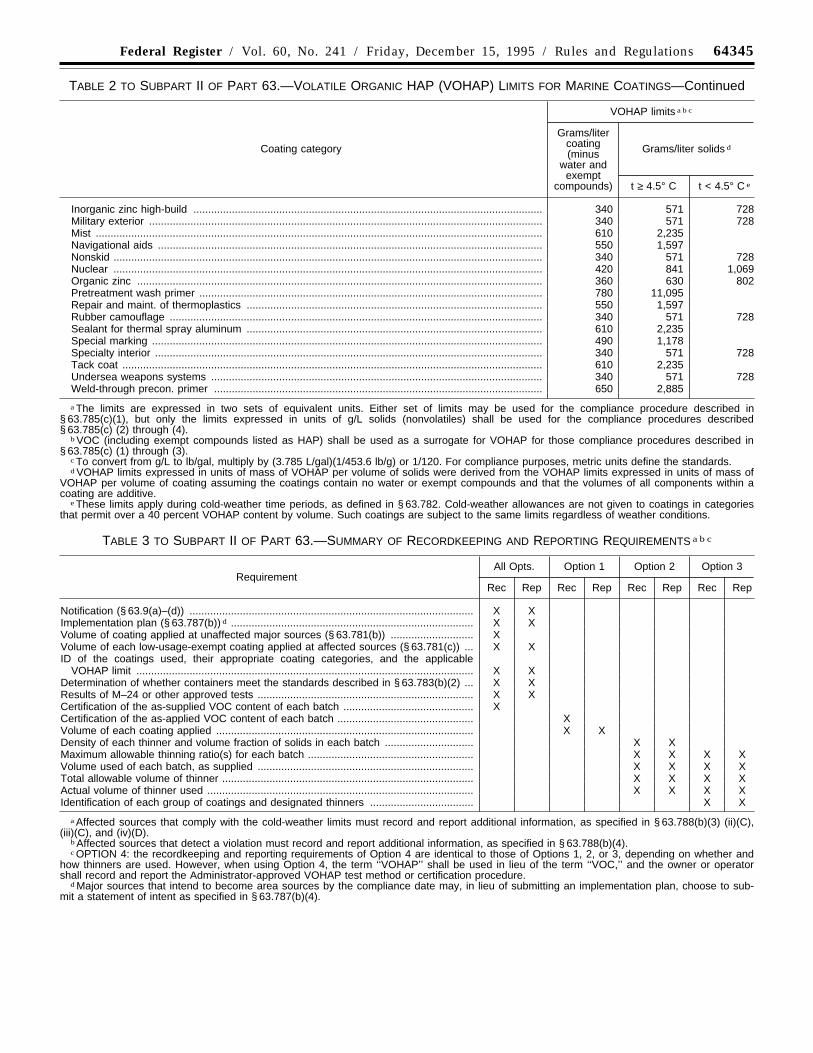
64345Federal Register / Vol. 60, No. 241 / Friday, December 15, 1995 / Rules and Regulations
TABLE 2 TO SUBPART II OF PART 63.—VOLATILE ORGANIC HAP (VOHAP) LIMITS FOR MARINE COATINGS—Continued
Coating category
VOHAP limits a b c
Grams/litercoating(minus
water andexempt
compounds)
Grams/liter solids d
t ≥ 4.5° C t < 4.5° C e
Inorganic zinc high-build ...................................................................................................................... 340 571 728Military exterior ..................................................................................................................................... 340 571 728Mist ....................................................................................................................................................... 610 2,235Navigational aids .................................................................................................................................. 550 1,597Nonskid ................................................................................................................................................. 340 571 728Nuclear ................................................................................................................................................. 420 841 1,069Organic zinc ......................................................................................................................................... 360 630 802Pretreatment wash primer .................................................................................................................... 780 11,095Repair and maint. of thermoplastics .................................................................................................... 550 1,597Rubber camouflage .............................................................................................................................. 340 571 728Sealant for thermal spray aluminum .................................................................................................... 610 2,235Special marking .................................................................................................................................... 490 1,178Specialty interior ................................................................................................................................... 340 571 728Tack coat .............................................................................................................................................. 610 2,235Undersea weapons systems ................................................................................................................ 340 571 728Weld-through precon. primer ............................................................................................................... 650 2,885
a The limits are expressed in two sets of equivalent units. Either set of limits may be used for the compliance procedure described in§ 63.785(c)(1), but only the limits expressed in units of g/L solids (nonvolatiles) shall be used for the compliance procedures described§ 63.785(c) (2) through (4).
b VOC (including exempt compounds listed as HAP) shall be used as a surrogate for VOHAP for those compliance procedures described in§ 63.785(c) (1) through (3).
c To convert from g/L to lb/gal, multiply by (3.785 L/gal)(1/453.6 lb/g) or 1/120. For compliance purposes, metric units define the standards.d VOHAP limits expressed in units of mass of VOHAP per volume of solids were derived from the VOHAP limits expressed in units of mass of
VOHAP per volume of coating assuming the coatings contain no water or exempt compounds and that the volumes of all components within acoating are additive.
e These limits apply during cold-weather time periods, as defined in § 63.782. Cold-weather allowances are not given to coatings in categoriesthat permit over a 40 percent VOHAP content by volume. Such coatings are subject to the same limits regardless of weather conditions.
TABLE 3 TO SUBPART II OF PART 63.—SUMMARY OF RECORDKEEPING AND REPORTING REQUIREMENTS a b c
RequirementAll Opts. Option 1 Option 2 Option 3
Rec Rep Rec Rep Rec Rep Rec Rep
Notification (§ 63.9(a)–(d)) ................................................................................................ X XImplementation plan (§ 63.787(b)) d .................................................................................. X XVolume of coating applied at unaffected major sources (§ 63.781(b)) ............................ XVolume of each low-usage-exempt coating applied at affected sources (§ 63.781(c)) ... X XID of the coatings used, their appropriate coating categories, and the applicable
VOHAP limit .................................................................................................................. X XDetermination of whether containers meet the standards described in § 63.783(b)(2) ... X XResults of M–24 or other approved tests ......................................................................... X XCertification of the as-supplied VOC content of each batch ............................................ XCertification of the as-applied VOC content of each batch .............................................. XVolume of each coating applied ....................................................................................... X XDensity of each thinner and volume fraction of solids in each batch .............................. X XMaximum allowable thinning ratio(s) for each batch ........................................................ X X X XVolume used of each batch, as supplied ......................................................................... X X X XTotal allowable volume of thinner ..................................................................................... X X X XActual volume of thinner used .......................................................................................... X X X XIdentification of each group of coatings and designated thinners ................................... X X
a Affected sources that comply with the cold-weather limits must record and report additional information, as specified in § 63.788(b)(3) (ii)(C),(iii)(C), and (iv)(D).
b Affected sources that detect a violation must record and report additional information, as specified in § 63.788(b)(4).c OPTION 4: the recordkeeping and reporting requirements of Option 4 are identical to those of Options 1, 2, or 3, depending on whether and
how thinners are used. However, when using Option 4, the term ‘‘VOHAP’’ shall be used in lieu of the term ‘‘VOC,’’ and the owner or operatorshall record and report the Administrator-approved VOHAP test method or certification procedure.
d Major sources that intend to become area sources by the compliance date may, in lieu of submitting an implementation plan, choose to sub-mit a statement of intent as specified in § 63.787(b)(4).

64346 Federal Register / Vol. 60, No. 241 / Friday, December 15, 1995 / Rules and Regulations
* Incorporation by reference—see § 63.14.1 Adapted from EPA–340/1–86–016 (July 1986),
p. II–2.2 The subscript ‘‘s’’ denotes each value is for the
coating ‘‘as supplied’’ by the manufacturer.3 Explain the other method used under
‘‘Remarks.’’
Appendix A to Subpart II of Part 63—VOCData Sheet 1
Properties of the Coating ‘‘As Supplied’’ bythe Manufacturer 2
Coating Manufacturer: llllllllllCoating Identification: llllllllllBatch Identification: lllllllllll
Supplied To: llllllllllllllProperties of the coating as supplied 1 to
the customer:A. Coating Density: (Dc)s ll g/L
[ ] ASTM D1475–90 * [ ] Other 3
B. Total Volatiles: (mv)s ll Mass Percent[ ] ASTM D2369–93 * [ ] Other 3
C. Water Content: 1. (mw)s ll Mass Percent[ ] ASTM D3792–91 * [ ] ASTM
D4017–90 * [ ] Other 3
2. (vw)s ll Volume Percent
[ ] Calculated [ ] Other 3
D. Organic Volatiles: (mo)s ll Mass PercentE. Nonvolatiles: (vn)s ll Volume Percent
[ ] Calculated [ ] Other 3
F. VOC Content (VOC)s:1. ll g/L solids (nonvolatiles)2. ll g/L coating (less water and exempt
compounds)G. Thinner Density: Dth ll g/L
ASTM ll [ ] Other 3
Remarks: (use reverse side)Signed: lllllll Date: ll
BILLING CODE 6560–50–P
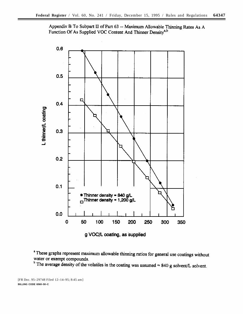
64347Federal Register / Vol. 60, No. 241 / Friday, December 15, 1995 / Rules and Regulations
[FR Doc. 95–29748 Filed 12–14–95; 8:45 am]BILLING CODE 6560–50–C
Appendix B
Inspector Training
Conduction Environmental Compliance Inspection Training
EPA Region 10
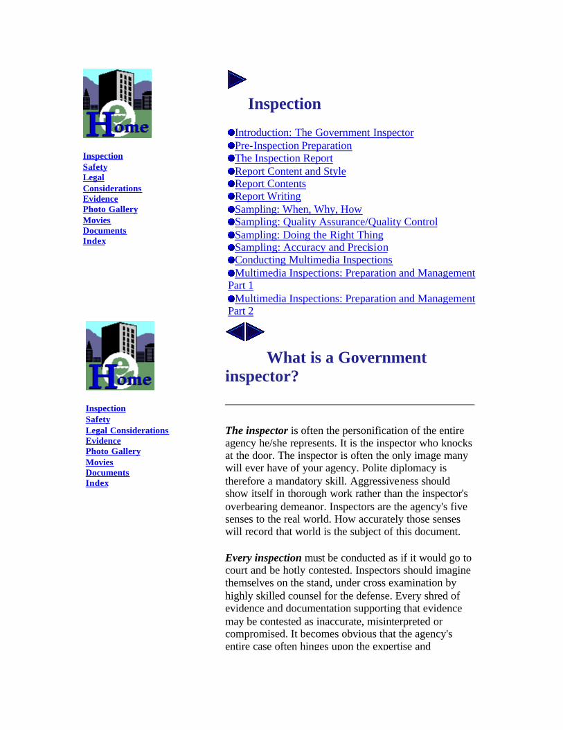
Inspection Safety Legal Considerations Evidence Photo Gallery Movies Documents Index
Inspection
Introduction: The Government Inspector Pre-Inspection Preparation The Inspection Report Report Content and Style Report Contents Report Writing Sampling: When, Why, How Sampling: Quality Assurance/Quality Control Sampling: Doing the Right Thing Sampling: Accuracy and Precision Conducting Multimedia Inspections Multimedia Inspections: Preparation and Management
Part 1 Multimedia Inspections: Preparation and Management
Part 2
Inspection Safety Legal Considerations Evidence Photo Gallery Movies Documents Index
What is a Government inspector?
The inspector is often the personification of the entire agency he/she represents. It is the inspector who knocks at the door. The inspector is often the only image many will ever have of your agency. Polite diplomacy is therefore a mandatory skill. Aggressiveness should show itself in thorough work rather than the inspector's overbearing demeanor. Inspectors are the agency's five senses to the real world. How accurately those senses will record that world is the subject of this document.
Every inspection must be conducted as if it would go to court and be hotly contested. Inspectors should imagine themselves on the stand, under cross examination by highly skilled counsel for the defense. Every shred of evidence and documentation supporting that evidence may be contested as inaccurate, misinterpreted or compromised. It becomes obvious that the agency's entire case often hinges upon the expertise and
professionalism of the inspector as the witness of fact. What does professional mean? You are an agent of the government, representing the very people you must regulate. Fairness and equity are cornerstones of your position. It is not uncommon for some individuals to become obsessive in the authority and power given to them. The axiom "... Power corrupts..." is true and requires constant attention to prevent. We are all equal citizens, subject to the same rules and social responsibilities. The following is an example of erroding ethics. In a basic inspector training class, a veteran inspector related the following photo documentation story. The trainer bragged that he had conducted more than 500 inspections in his 18 year career. He said that photography was a vital part of documentation but in his opinion, it was often dangerously over used. As an example of this over use, the inspector showed half a dozen slides taken at an alleged hazardous waste site. The photographs clearly showed the government's site manager on his knees, in street clothes, scooping a sample with his bare hands. The instructor said that the photographs should not have been taken or should have been destroyed, because they eventually hurt the agency's case by making the site appear less hazardous. This "veteran" had totally missed the point. Improper protocol and cover up is neither professional or ethical. The error was not following the proper sampling procedure, not the photography. It is imperative that the inspector set the example in the implementation of proper procedure. Those procedures must routinely be better implemented by the regulators than those performed by the regulated community. Comparisons between the government's work and that of the regulated community is often at issue in court. Agents of the government should never feel justified in hiding their own impropriety in order to enforce against those they regulate. A little bias can rapidly lead to decay if unattended. How would you like to be treated by a government inspector? Apply the "Golden Rule" to your work. As an agent of the government you must constantly strive to maintain the highest standards of thoroughness, ethical conduct and quality assurance. Inspectors must train and retrain so that he or she can set an unimpeachable example for those whose laws they
enforce.
Inspection Safety Legal Considerations Evidence Photo Gallery Movies Documents Index
Pre-Inspection Preparation Half the Fun is Getting There
In The Office and Off Site About 50% of your time should be spent planning and preparing for your inspection. This will prevent classic oversights; like being on the road and realizing you have no clue how to get to your facility, or walking right past the operation which received a Notice of Violation (NOV) in five previous inspections.
History and Liaison Work Your first objective should be to check with the program staff and files to gain all the knowledge you can about the site. There may be personnel assigned to the specific facility you are to inspect. Other considerations are permits, litigation, or special agreements. There may be other inspectors who have experience with facility.
There may be other agencies or programs which have been involved or should be involved. Not informing an entity that feels territorial about a facility can cause serious backlash. Showing up at a facility used to seeing a particular individual or agency will usually alarm the facility. If that individual or agency does not support your bing there, life can be difficult. Make sure your immediate chain of command is familiar with your objectives and schedule. New inspectors often complain that there is little supervisory support for their field work. This is usually because supervisory staff was not fully informed and prepared bfo re you did the work.
Reconnaissance Drive by and have a look before you leap into the inspection. Have a cup of coffee at the local diner and consider the possibilities and organize your approach. Use the time to review your kit and checklist. The facility is never what you anticipated at the office. Just
when you begin to think you can dance around any contingency, one comes up and nails you.
Consider the site layout, safety considerations, places and operations you want to include in your tour, and what is "going on" before they know you are there and the "going on" stops. Prepare Your Kit For Action Load your camera. Fill out your paperwork as much as you can before entering the site. It is a nuisance when you end up hurriedly doing it in front of an impatient plant manager, who has taken time off from a union negotiation or a critical break down just to deal with you. Exchanging business cards is a good way to introduce yourself and get information about your site contacts without lengthy and redundant questioning. You may even want to write a few reminders in your notebook to make sure you cover a topic or see an operation before you leave. One recommended item is athe "post it®" that can be used to mark things you want to copy, or to identify things in photographs.
Sampling Are you prepared to sample? Do you have a sample plan? Have you notified the laboratory of your intentions? Labs do not like unannounced, high priority samples.
Inspection Safety Legal Considerations Evidence Photo Gallery Movies Documents Index
The report is the clear, succinct, factual and objective description of everything relevant to what you did.
The permanent product of an inspection or investigation is the report. You probably won't be the one that uses the report so you should write it so that the case could proceed without you. One clue of an inadequate report is if agency counsel or the program review staff have to keep calling you to clarify things in the report.
The report is the collection of everywhere you went,
everything you did and everything you obtained. It answers the questions of who, what, where, when, why and how. It is logical and accurate. It is conc ise yet complete. It identifies all areas of regulatory concern that were covered and what was found. And it does this clearly, succinctly, factually and objectively.
HOW IS THIS DONE?
A. The report is constructed so that it has a professional appearance.
1. It should be written in the active voice. "Joe asked Susan where the waste drums were."
2. It should be written in the first person. "I asked Joe where he lived."
3. It should be written in a logical order. 4. It should be written so that information in clear
and easy to find.
B. The report is grammatically sound. This does not mean that it is written in excessively formal or technical language. It means that it avoids the use of colloquialisms, jargon, or offensive language. It uses good sentence and paragraph structure. Words are used and spelled correctly.
1. Sentences should be simple and direct rather than complex or convoluted. Clarify information rather than making it unnecessarily complicated.
2. Use words appropriately and use words that are found in common usage. The report is often read by those with less technical knowledge than you have.
C. The report is factual and objective.
1. Who did what, when, where, why and how? 2. State opinions as opinions and not as facts. 3. Write so that the reader can reach their own
conclusion from the logically ordered facts presented in the report.
4. If you choose to state a conclusion, you should identify the logic, information and procedure you used to reach that conclusion.
5. All mathematical, scientific or technical
conclusions must be accompanied by the method and calculations.
Inspection Safety Legal Considerations Evidence Photo Gallery Movies Documents Index
Write the report as you did the inspection.
1. I did this... 2. I asked Joe Dokes... 3. I sampled the... 4. Mary Dokes said...
Style is often interpreted as discretionary by various program offices. In the court room, style is strictly "first person singular." If your office insists upon passive voice such as "it was determined" rather than the active "I" or "Joe determined," they should consult appropriate experienced counsel. The less translation between the report and testimony, the better.
Good reports are not great prose. Good reports are a detailed narrative of what happened during a specific event in time. Clarity is far more important than sounding academic.
Avoid unnecessary or "cop talk" jargon. Say "Joe Dokes got out of the GMC truck," rather than, "The perpetrator exited the utility vehicle."
Avoid drawing conclusions. Write the facts in such clarity that the reader can draw their own conclusion. "Joe was very hostile," is a conclusion. "Joe began swearing and punching holes in the wall," is a statement of events from which the reader can draw their own conclusions.
Avoid making assumptions. "I determined that the records were acceptable after a review of several examples." The most you can say is that in your opinion, the specific records reviewed appeared acceptable to you. In most cases you should take example copies of
those records and also allow the program to review them and make a determination.
Inspection Safety Legal Considerations Evidence Photo Gallery Movies Documents Index
Report Contents: The 5 'W's
1. What is it? 2. Where did you do What? 3. Who let you do it and who did you do it with? 4. When did it happen? 5. Were samples taken?
The following outline of report subsections has been generally accepted throughout the program offices of most EPA Regions, National Enforcement Investigations Center (NEIC) and the Office of Regional Counsel.
Heading This should include the type of inspection, site or activity name, and date of the inspection.
Facility Address Corporate or head office address.
Site Address Exact geographic location of the site.
Site Contacts Name, position or title, and telephone number.
Inspection Team Leader and all members of the inspection team. Name, position or title, and telephone number.
Site History This includes compliance history, and the history of the facility site location.
Inspection Times The hour, day and year for the inspection (e.g. 2-19-1996 @ 0800 hours)
Opening Conference Who did you show your credentials to; all persons present; titles or positions; what was discussed (i.e. scope and timing of the inspection events); specific arrangements; if entry was granted or
denied.. Field Inspection
Narrative of the field inspection events and observations. Where did you go? What did you see? What did you do?
Record Inspection What was reviewed, copied and taken? Where were the records kept and who was in charge of them? What selection method was used?
Closing Conference Who was there? What was discussed? What was agreed to?
Samples Were samples taken? Of what? Were there splits?
Compliance Concerns State as your opinion only. Regulations may be cited in the report or may be cited in an "enforcement confidential" memorandum to the program chief or attorney in ORC. Some attorneys have strong feelings against the inspector drawing any enforcement conclusions at all, because it may complicate the agency's discretionary powers.
Attachments List and identify all notes, documents, photographs, notices, and documentation. This may be done in an index of attachments or in the inspection narrative itself.
Date and Signature It is your report, so sign it!
It is often a good idea to have someone else read your draft report before placing it in final. They are often able to point out ways to clarify things you may have overlooked.
Inspection Safety
Report Writing: Words and Phrases to Avoid
Legal Considerations Evidence Photo Gallery Movies Documents Index
So why is it so important to avoid some words and phrases? They are beyond the knowledge of the inspector, they are ambiguous, or they are not substantiated or supportable by documentation. They can limit the choices open to the agency by seeming to prejudge the issue by drawing a premature conclusion. They can also be so vague that they do not answer the who, what, where, why, and how questions your report must address.
1. All is so absolute that any exception can throw the issue into question. For example don't say you saw all the records. You might be able to say that you saw all the drums in the storage area with more confidence.
2. Always, again, is an absolute term. Always does not allow for an exception, and exceptions usually exist.
3. Never is also an absolute term. One exception and you may have trouble.
4. Violations , as in "there were violations, " or "that was a violation," is reaching a conclusion. Rarely should the inspector also be the one who determines if there is a violation. What if you were wrong? The company could sue you for expenses or damages. You may not have supplied enough credible documentation to substantiate the violation. You would be making an institutional decision without using the system of checks and balances built into the program. If you have that authority, recognize your liability.
5. No Violations is also reaching a conclusion. Changes in interpretations can alter whether action is possible or not. Only the appropriate counsel may know recent court decisions.
6. It Was Determined is vague and does not say who determined. If you made a judgment call, say so. "I determined that the transformer was leaking because dielectric fluid was flowing from a hole in the side." If you reach a conclusion make sure that (1) you are qualified to make that determination, and (2) you document it well enough that others can reach the same conclusion.
7. They Said is also vague. Who said? I said. Joe said. The woman receptionist in the red dress said.
These are far more specific and who said what can be critical to a case.
The report should clarify information. It should also simplify, so that readers less qualified than the writer can reach their own conclusions. Avoid unnecessary high tech language. Judges or attorneys seldom have engineering or chemistry degrees.
Inspection Safety Legal Considerations Evidence Photo Gallery Movies Documents Index
Sampling: When, Why, How
When to Consider Taking Samples
1. There is no data available 2. There is insufficient data 3. The available data is in doubt 4. Data is needed to document an event 5. Sampling is required by law or permit
Sampling and sample analysis may be necessary to document potential evidence of noncompliance or compliance. Samples are expensive. Make sure they are necessary. At the most fundamental there are two types of sampling: (1) Composite samples and (2) Grab samples. However, either of these may be planned or samples of opportunity.
Samples of opportunity are events that were not generally anticipated. They may be required because of a new process or expansion or they may be necessary because of a spill or discharge.
Regardless of the circumstances there must be a project plan and a method identified for the specificity (what chemical to look for) and chemical concentration (such as parts per million) required from the analysis. If it was not in the site specific project plan then it should be in a Standard Operating Procedure (SOP) kept on file. Regardless of the SOP or QA requiements, all samples must be representative of the material or event.
SOPs are written documented procedures that should be used for collecting any type of sample.
Each organization or agency should have SOPs on file. This insures defensible repeatability and consistency and a written record of what was done which may have to be referred to several years after the sampling event. Use only laboratories that adhere to written SOPs. While there may be modifications of the method to fit unique circumstances, all deviations from the SOP must be thoroughly documented.
This is a big responsibility for the inspector. Lets summarize what we have so far. Your sample must be representative. It must have been taken and analysed using an appropriate SOP. You must identify the appropriate method of analysis in your site specific quality assurance project plan (QAPjP) and you must have notified the laboratory of the specificity and chemical concentration required in their analytical report.
This brings us to the area of overall responsibility for quality assurance and quality control of the entire sampling event. That falls squarely upon the lead inspector. The inspector must control and insure that proper methods and procedures are followed throughout the entire process from acquiring "clean" sample containers, transporting those containers in the field without contaminating them, taking the samples, transporting them back to the laboratory without contaminating them, determining the method of analysis, what chemicals to analize for and how small of a concentration they should look for. This is a big order and may require assistance from QA or Lab personnel.
Inspection Safety Legal
Sampling: Quality Assurance/Quality Control
What and Why You Are Sampling Will Determine the Method the Method You Should Use
Considerations Evidence Photo Gallery Movies Documents Index
There are many confusing terms used in various programs which relate to the same general issues. It is the inspector/investigator's responsibility to keep track of his/her own objectives and translate those objectives into the jargon of each media. Help is available from the QA office.
The Quality Assurance Project Plan (QAPjP) is the overall recipe for a legally supportable activity with subsets that cause data translation into a language required for enforcement and eventual referral to the agency counsel. Even the best and most experienced inspectors have trouble with these translations from time to time. A major function of the QA/QC program office is to assist the inspector or Project Manager (PM) in assigning tasks and setting sample parameters and language for reporting data.
The lead inspector is the on-scene Project Manager (PM) and responsible for generating a viable package for case referral. No one else has the overall perspective to generate the QAPjP and determine the methods, protocols, and field modifications necessary to make a good case. If you have a Quality Assurance office they will help you. If not, you can contact your laboratory and thoroughly review what is required to make the sampling event productive and useful.
Once the appropriate method is selected, the inspector must then determine the precision and accuracy. This means the analysis will identify the proper chemical and concentration of that chemical with an acceptable level of accuracy and confidence. Precision and Accuracy impact QA/QC, the laboratory, media programs and enforcement. For example, the inspector knows that for a particular substance 1,000 ppm is the action point for enforcement, yet the methodologies may produce data in + or - percentiles. The inspector must insure that the laboratory uses a methodology that will report results in a usable format for taking action. The inspector must understand and manage how precision and accuracy is applied to both field sampling and lab analysis.
The Project Manager (PM) is responsible for QA/QC. The PM is accountable for the technical accuracy and legal supportability of the entire referral package.
The QAPjP is the recipe for all technical activities. It must be technically accurate and
legally supportable through ties to policy and established standards acceptable to a judge.
What and why you are sampling will determine the method you should use. It is the PM's responsibility to assure that the correct methods are selected and documented satisfactorily.
The QA/QC office should be able and willing to assist the PM in developing the best methodologies to insure appropriate and technically supportable data.
The PM's name is on the bottom line. They will have to take the stand in court to defend all activities. Take charge and know what you are doing.
Inspection Safety Legal Considerations Evidence Photo Gallery Movies Documents Index
Sampling: Doing the Right Thing
If you cannot maintain Quality Assurance (QA) and Quality Control (QC) you should not take the samples at all. Each sample must be supported with documentation providing the 5-W's and the key word How. Without that documentation, it will be impossible to establish the three criteria (F.A.R) for evidence admissibility.
When and why should you take samples? The first call on that is the lead person in the field...you!
• When to sample is determined by the best chance to obtain a representative sample.
• Why a sample is taken is more subjective. It is initiated if there is a lack of confidence in available data or because of incomplete data at the facility or home office.
Sample documentation centers around three prime issues: representativeness, tracking and methodology:
• Was the representative of what you needed to evaluate for compliance? Does it represent a specific waste stream, site, event or activity?
• Can you prove where it came from, where it went, what was done to it, and that there was not an opportunity to compromise the sample along the way through your tracking documentation?
• Was the correct methodology followed to insure that your sample was (1) taken properly for the substance in question, and (2) the proper analytical method was used to make an accurate evaluation of its presence.
What are some of the tools used to accomplish thorough tracking?
• Field Log or Notebook • Field Photography • Field Lab Data Sheet • Sample Number
• Analysis Request • QAPjP • Sample Plan • Check Lists • Field Generated Diagrams and Maps • Chain of Custody • Lab Sample Traffic Report
Inspection Safety Legal Considerations Evidence Photo Gallery Movies Documents Index
Sampling: Precision and Accuracy
All of these things we just talked about should be included in a site specific Quality Assurance Project Plan (QAPjP). This can be burdensome but it's the lynch pin of successful case development. Remember your data must be better than their data. Only the inspector has the perspective to control all these sample steps. If the inspector is weak in the technical or chemical aspects of sampling, it falls to them to make the necessary liaison contacts to ensure that
there is a qualified team approach to sampling procedure and handling. Get to know your lab and quality assurance personnel and make sure that they understand the need to
apply appropriate protocols. Help them to understand the difficulties in applying some methods in the field where conditions change minute by minute.
Now we come to a really complicated aspect of sampling and what is required when you request an analysis. The method
you choose must provide the necessary the precision and accuracy. Technically here are acceptable analytical chemistry definitions for these terms:
• Accuracy denotes the nearness of a measurement to its accepted true value and is expressed in terms of error.
• Precision refers to the reproducibility of results. It is the agreement between the numerical value of two or more measurements that have been made in an identical fashion. Still not clear?
Let's try a metaphor. Think of shooting at a bull's-eye in target practice. Accuracy refers to selecting and hitting the bull's eye. Precision refers to how small your group will be and how close they will average to that bull's eye. The bull's-eye's center represents the exact true value of the target chemical and anything away from that center is measured as the amount of error. The closer to the center of the bull's eye the greater the accuracy or detection of the true value. Deviation has two major considerations. Even if you use the same shooter, the same gun, the same distance, weight and speed of bullet and every other variable you can think of, you will still not put all shots into the same hole. They will differ in their distance from the true value center of the bull's-eye and how closely they group together. These are often referred in terms of deviation and variance. This error in the ability to repeat each shot is a measurement of precision.
DISCUSSION: The above metaphor is a little faulty. Discuss how other variables such as sample technique,
calibration of field and/or lab equipment, etc. can add to the considerations. Lab reports are frequently given with a
confidence factor which may be measured in + or - percentiles. There may be other chemicals that mask the target chemical or a flyer which is a wild
outlying data point. Can the data still be used? How would precision and accuracy relate to the quantity of target material.
Inspection Safety Legal Considerations Evidence Photo Gallery Movies Documents Index
Conducting Multimedia Inspections
The steps required for a single media inspection stay in effect for Multimedia inspections. However, Coordination, Chain of Command, Confidentiality and Communication gain a higher sensitivity and importance.
Multimedia inspections are broad spectrum, politically sensitive and resource consumptive compliance activities. Multimedia inspections have high visibility. They achieve a "snap shot in time" of a facility's compliance under several or many regulatory authorities. Along with criminal enforcement , multimedia inspections represent a significant portion of the total compliance impact on the regulated community and can provide a better foundation to establish more efficient and innovative routes to compliance.
Multimedia inspection activities require all the methods used in single media inspections but differ from single media inspections by elevating the importance of teamwork, confidentiality, chain of command, communication and coordination:
1. Teamwork is vital to the ultimate success of every activity in a Multimedia inspection. No "Lone
Rangers". Neophyte or even veteran single media inspectors may not realize
the necessity to work as a member of a team. 2. Enforcement Confidentiality must be maintained
throughout the entire process from the earliest planning stages to enforcement referral. This applies to all activities and communications. The routineness of some single media inspections may cause some inspectors to forget they are part of a team
3. A Chain of Command must be maintained. Activities must be coordinated carefully to insure efficient management, QAQC and controlled communication of confidential communications.
4. Communication must be maintained through all phases of the planning, preparation and execution of the inspection.
5. Coordination between all of the regulatory actors is crucial.
Note: Multimedia inspections are an Agency level activity rather than an individual media or program activity. That means you must use "Teamwork", Confidentiality, Chain of Command, Communication and Coordination in all the preparation.
Inspection Safety Legal Considerations Evidence Photo Gallery Movies Documents Index
Multimedia Inspections: Preparation and Management Part 1
Some typical sensitive issues are: The facility may have heard about it through the grapevine. Facility representatives may ask why the facility was picked. You may hear complaints from your own agency that the inspection conflicts with complex negotiations in other programs, even when every effort was made to keep them on board with every phase of planning. One of the
regulatory program offices may ask you to postpone or cancel the inspection at the eleventh hour because they have a conflict. Site project managers from special programs like emergency clean up or Superfund may say you didn't give them proper warning or get their permission. And God help you if the press gets hold of it. What else could go wrong? How can you minimize conflicts?
The following are typical of the early planning phases of a Multimedia inspection:
1. Targeting through a neutral inspection scheme by the cooperative input of EPA and State Agencies.
2. "Need to Know" distribution of information to State and EPA Managers .
3. Deciding which media should be covered at each targeted site.
4. Selection of specific MM field coordinators for each site inspection.
5. Scheduling by those responsible for coordinating and conducting the inspections.
6. Establishment of the inspection team for each site and which inspector will be responsible for which media.
It is imperative that confidentiality be maintained throughout Multimedia planning and scheduling. Even the most casual mention of a targeted site can leak out and create frustrating and unnecessary damage control. Communication should be kept to face to face contact, controlled telephone access, or written communication stamped "Enforcement Confidentia l".
Avoid the following:
1. Public mention of the site 2. Uncontrolled notes or memos 3. Mention of the site to those not involved directly
with the inspection
Inspection Safety Legal Considerations Evidence Photo Gallery Movies Documents Index
Multimedia Inspections: Preparation and Management Part 2
Keep these things in mind when participating in a Multimedia Inspection:
1. Maintain strict confidentiality at all times. 2. Keep the Inspection Team Coordinator informed
prior to and dur ing the inspection. 3. Find out if you will be participating with a state or
EPA counterpart and communicate directly with that person when planning the inspection.
4. All written or electronic communications regarding the site or inspection should have "Enforcement Confidential, Do not release under FOIA" clearly noted on their cover.
5. Strive to work as a team member during the planning and execution of the inspection.
6. Don't telegraph the inspection to the facility. If it is to be an announced inspection, it should be done by a person and method that is mutually agreeable with all the programs and agencies involved.
7. Get your inspection report drafted quickly so that debriefing can take place promptly after the inspection is completed. Many will need a general idea of the compliance issues resulting from the inspection.
8. Insure that the program office does not undertake unilateral action without informing the appropriate Multimedia enforcement coordinator.
MM-Inspections require journeyman level personnel in each lead position.
Inspectors taking the lead for any individual media must meet minimal criteria which include the following:
1. Completion of basic inspector training certification (Required by EPA Order 3500.1).

2. Completion of minimal specific media training 3. Knowledge of agency's policies and procedures on the following topics:
a. Inspection authorities b. Entry procedures/problems c. Enforcement action procedures and policies d.Common legal issues encountered during and resulting from inspections e. Basic safety procedures and concerns f. Specific safety concerns for the facility being inspected
4. Thorough familiarity with Quality Assurance requirements:
a. Sample collection b. Identification and preservation c. Chain of custody procedures
5. Knowledge of relevant industrial processes, waste control and waste monitoring 6. Documentation skills through uses of the following:
a. Interviews b. Photography c. Document and record review d. Technical and investigatory deductive reasoning e. Communication skills (verbal and written)
7. Basic understanding of the procedures for obtaining administrative warrants, affidavits, technical requirements for warrant application and warrant procedures for serving warrants and obtaining and documenting warrant returns.
Team leaders should be senior journeymen with expertise in leading at least two media investigations. In addition team leaders should have experience and skills in the following:
1. Demonstrated leadership skills 2. Skills in project management 3. Experience leading one or more single media
inspections as part of a Multimedia inspection 4. Demonstrated tact and diplomacy in dealing with the
regulated community and other regulatory authorities 5. They must also serve as liaison, project coordinator
and insure QAQC.
Other Concerns in the Field
1. Report any observations, materials or events that may be of interest to other team members. This is a team effort and information should be freely exchanged among inspection team members. 2. Keep confidential information under strict control.
a. Keep confidential information and subjective observations with team members private. b. Keep all team documentation, project plans, safety plans and logbooks secure and under strict document control. c. Sensitive discussions should not take place on facility telephones where they may be overheard.
3. Laboratory samples and materials must be maintained under chain-of-custody at all times. 4. Restrict on-site activities to normal working hours as much as possible. 5. Keep the Team Leader informed of all contingencies and events that may alter existing schedules or procedures. 6. Single media inspection leaders should not talk to the press without coordinating with the Team Leader first. Usually the Team Leader should handle all media contacts and those should be very limited and planned beforehand. Agency coordination is usually advisable. 7. Always maintain a thorough, polite, and professional
demeanor. 8. Do not criticize any team activity, another member of the team or associated agency in public or private at any
time during the inspection.
Scheduling
Sequencing of specific media may vary based upon inspection priorities. If the inspection is broad in scope, complex because of an extensive permit or involves sampling, it will usually be scheduled toward the beginning of the inspection period to allow extra time for contingencies. The following is a typical sequence:
Every site requires continual adjustment and modification of the team schedule and methodologies. Each step must be justified and defensible through QAQC documentation. Not doing this could negate the viability of the entire effort.
Inspection Safety Legal Considerations Evidence Photo Gallery Movies Documents Index
Conducting Environmental Compliance Inspections U.S. Environmental Protection Agency Region 10, Office of Environmental Assessment, Investigations and Engineering Unit
Training Modules | Class Schedule | Who to Contact | About This Site
Contact: Doug Smith Last Update: March 12, 1997
Appendix C
A Guidebook on How to Comply with the Shipbuilding And Ship Repair (Surface Coating) Operations National
Emissions Standards for Hazardous Air Pollutants EPA 453/B-97-001
January 1997
United States Office of Air Quality EPA 453/B-97-001Environmental Protection Planning and Standards January 1997Agency Research Triangle Park, NC 27711
Air
EPA A Guidebook on How to
Comply with the Shipbuilding
and Ship Repair (Surface
Coating) Operations National
Emission Standards for
Hazardous Air Pollutants
A GUIDEBOOK ON HOW TO COMPLY WITH THE SHIPBUILDING AND SHIP REPAIR
(SURFACE COATING) OPERATIONSNATIONAL EMISSION STANDARDS
FOR HAZARDOUS AIR POLLUTANTS
Coatings and Consumer Products GroupEmission Standards Division
Office of Air Quality Planning and StandardsU. S. Environmental Protection Agency
Research Triangle Park, NC 27711

January 1997
ii
This report has been reviewed by the Emission Standards Division (ESD), Office ofAir Quality Planning and Standards (OAQPS), U. S. Environmental Protection Agency(EPA), and approved for publication. Mention of trade names or commercial products is notintended to constitute endorsement or recommendation for use. For more information on thisregulation, please call your State or local air pollution control agency; your local, regional, ornational shipbuilding trade association; or your EPA Regional Office. Contact EPA's ControlTechnology Center (CTC) Hotline at (919) 541-0800 to get information on air programcontacts. To order single copies of this guidebook, contact the Library Services Office(MD-35), U. S. EPA, Research Triangle Park, NC 27711; the OAQPS Technology TransferNetwork (TTN), (919) 541-5742 via modem (for assistance with the TTN, call (919) 541-5384) or via the Internet at http:\\ttnwww.rtpnc.epa.gov; or the National TechnicalInformation Services, 5285 Port Royal Road, Springfield, VA 22161.
iii
TABLE OF CONTENTS
Page
CHAPTER 1 INTRODUCTION . . . . . . . . . . . . . . . . . . . . . . . . . . . . . . . . 1
CHAPTER 2 OVERVIEW OF THE REGULATION . . . . . . . . . . . . . . . . . . . 3
CHAPTER 3 DOES THIS REGULATION APPLY TO ME? . . . . . . . . . . . . . 9
CHAPTER 4 WHAT DO I NEED TO DO TO COMPLY? . . . . . . . . . . . . . . . 13
CHAPTER 5 HOW WILL I DEMONSTRATE COMPLIANCE? . . . . . . . . . . . 17
CHAPTER 6 WHAT RECORDKEEPING AND REPORTING WILL I NEED TO DO? . . . . . . . . . . . . . . . . . . . . . . . . . . . . . . . . . . . . . . 23
CHAPTER 7 WHAT ARE MY POLLUTION PREVENTION OPTIONS? . . . . . 27
CHAPTER 8 HOW DOES THIS REGULATION RELATE TO OTHERFEDERAL AND STATE OR LOCAL REQUIREMENTS? . . . . . . 29
CHAPTER 9 HOW MUCH WILL IT COST? . . . . . . . . . . . . . . . . . . . . . . . 31
CHAPTER 10 WHERE CAN I GO FOR MORE INFORMATIONAND ASSISTANCE? . . . . . . . . . . . . . . . . . . . . . . . . . . . . . . 35
APPENDIX A. FEDERAL REGISTER NOTICES: FINAL REGULATION AND DIRECTFINAL REGULATION
APPENDIX B. GLOSSARY OF TERMS
APPENDIX C. LIST OF ESTIMATED NESHAP MAJOR-SOURCE SHIPYARDS
APPENDIX D. EXAMPLE INITIAL NOTIFICATION
APPENDIX E. EXAMPLE IMPLEMENTATION PLAN
APPENDIX F. EXAMPLE FORMS
APPENDIX G. EXAMPLE CALCULATIONS
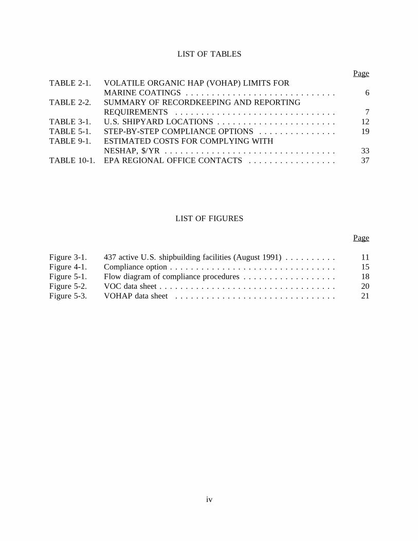
iv
LIST OF TABLES
PageTABLE 2-1. VOLATILE ORGANIC HAP (VOHAP) LIMITS FOR
MARINE COATINGS . . . . . . . . . . . . . . . . . . . . . . . . . . . . . 6TABLE 2-2. SUMMARY OF RECORDKEEPING AND REPORTING
REQUIREMENTS . . . . . . . . . . . . . . . . . . . . . . . . . . . . . . . 7TABLE 3-1. U.S. SHIPYARD LOCATIONS . . . . . . . . . . . . . . . . . . . . . . . 12TABLE 5-1. STEP-BY-STEP COMPLIANCE OPTIONS . . . . . . . . . . . . . . . 19TABLE 9-1. ESTIMATED COSTS FOR COMPLYING WITH
NESHAP, $/YR . . . . . . . . . . . . . . . . . . . . . . . . . . . . . . . . . 33TABLE 10-1. EPA REGIONAL OFFICE CONTACTS . . . . . . . . . . . . . . . . . 37
LIST OF FIGURES
Page
Figure 3-1. 437 active U.S. shipbuilding facilities (August 1991) . . . . . . . . . . 11Figure 4-1. Compliance option . . . . . . . . . . . . . . . . . . . . . . . . . . . . . . . . 15Figure 5-1. Flow diagram of compliance procedures . . . . . . . . . . . . . . . . . . 18Figure 5-2. VOC data sheet . . . . . . . . . . . . . . . . . . . . . . . . . . . . . . . . . . 20Figure 5-3. VOHAP data sheet . . . . . . . . . . . . . . . . . . . . . . . . . . . . . . . 21
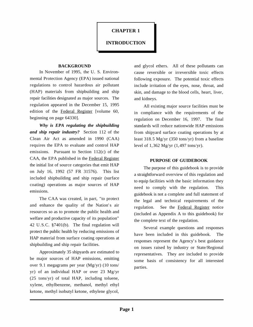
Page 1
CHAPTER 1
INTRODUCTION
BACKGROUNDIn November of 1995, the U. S. Environ-
mental Protection Agency (EPA) issued nationalregulations to control hazardous air pollutant(HAP) materials from shipbuilding and shiprepair facilities designated as major sources. The
regulation appeared in the December 15, 1995edition of the Federal Register [volume 60,beginning on page 64330].
Why is EPA regulating the shipbuildingand ship repair industry? Section 112 of the
Clean Air Act as amended in 1990 (CAA)requires the EPA to evaluate and control HAPemissions. Pursuant to Section 112(c) of the
CAA, the EPA published in the Federal Registerthe initial list of source categories that emit HAPon July 16, 1992 (57 FR 31576). This listincluded shipbuilding and ship repair (surface
coating) operations as major sources of HAPemissions.
The CAA was created, in part, "to protectand enhance the quality of the Nation's airresources so as to promote the public health andwelfare and productive capacity of its population"
42 U.S.C. §7401(b). The final regulation willprotect the public health by reducing emissions ofHAP material from surface coating operations atshipbuilding and ship repair facilities.
Approximately 35 shipyards are estimated tobe major sources of HAP emissions, emitting
over 9.1 megagrams per year (Mg/yr) (10 tons/yr) of an individual HAP or over 23 Mg/yr(25 tons/yr) of total HAP, including toluene,xylene, ethylbenzene, methanol, methyl ethyl
ketone, methyl isobutyl ketone, ethylene glycol,
and glycol ethers. All of these pollutants cancause reversible or irreversible toxic effectsfollowing exposure. The potential toxic effectsinclude irritation of the eyes, nose, throat, and
skin, and damage to the blood cells, heart, liver,and kidneys.
All existing major source facilities must bein compliance with the requirements of theregulation on December 16, 1997. The finalstandards will reduce nationwide HAP emissions
from shipyard surface coating operations by atleast 318.5 Mg/yr (350 tons/yr) from a baselinelevel of 1,362 Mg/yr (1,497 tons/yr).
PURPOSE OF GUIDEBOOK
The purpose of this guidebook is to providea straightforward overview of this regulation andto equip facilities with the basic information theyneed to comply with the regulation. This
guidebook is not a complete and full statement ofthe legal and technical requirements of theregulation. See the Federal Register notice(included as Appendix A to this guidebook) for
the complete text of the regulation.
Several example questions and responses
have been included in this guidebook. Theresponses represent the Agency's best guidanceon issues raised by industry or State/Regionalrepresentatives. They are included to provide
some basis of consistency for all interestedparties.

INTRODUCTION CHAPTER 1
Page 2
THIS PAGE INTENTIONALLY LEFT BLANK
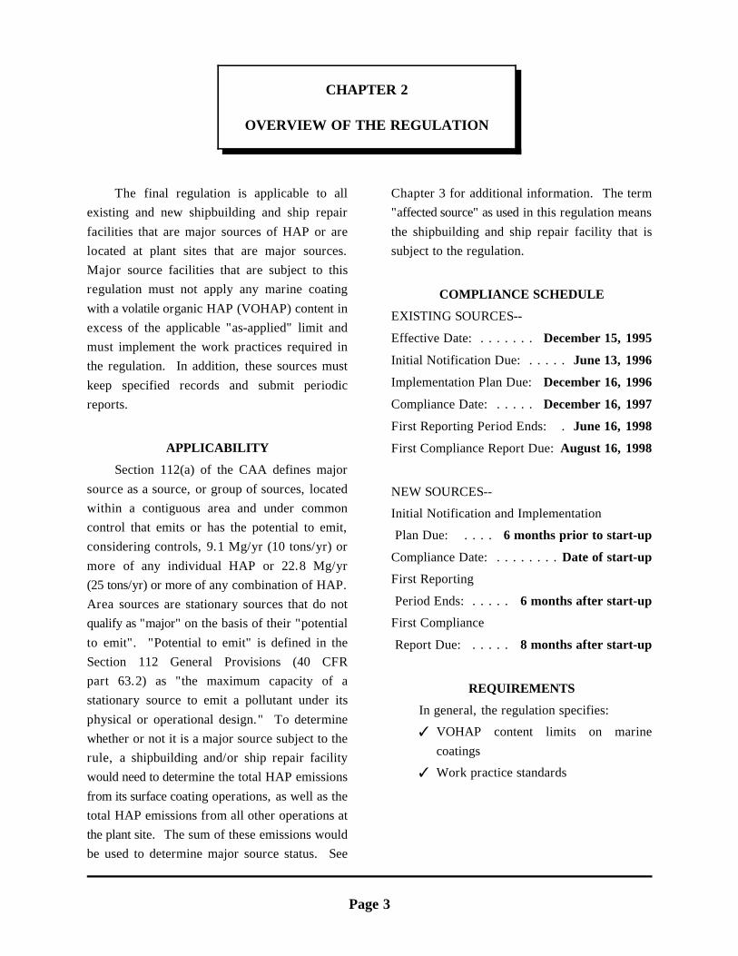
Page 3
CHAPTER 2
OVERVIEW OF THE REGULATION
The final regulation is applicable to all Chapter 3 for additional information. The termexisting and new shipbuilding and ship repair "affected source" as used in this regulation means
facilities that are major sources of HAP or are the shipbuilding and ship repair facility that islocated at plant sites that are major sources. subject to the regulation.Major source facilities that are subject to thisregulation must not apply any marine coating
with a volatile organic HAP (VOHAP) content inexcess of the applicable "as-applied" limit andmust implement the work practices required inthe regulation. In addition, these sources must
keep specified records and submit periodicreports.
APPLICABILITY
Section 112(a) of the CAA defines major
source as a source, or group of sources, locatedwithin a contiguous area and under commoncontrol that emits or has the potential to emit,considering controls, 9.1 Mg/yr (10 tons/yr) or
more of any individual HAP or 22.8 Mg/yr(25 tons/yr) or more of any combination of HAP.Area sources are stationary sources that do notqualify as "major" on the basis of their "potential
to emit". "Potential to emit" is defined in theSection 112 General Provisions (40 CFRpart 63.2) as "the maximum capacity of astationary source to emit a pollutant under its
physical or operational design." To determinewhether or not it is a major source subject to therule, a shipbuilding and/or ship repair facilitywould need to determine the total HAP emissions
from its surface coating operations, as well as thetotal HAP emissions from all other operations atthe plant site. The sum of these emissions wouldbe used to determine major source status. See
COMPLIANCE SCHEDULE
EXISTING SOURCES--
Effective Date: . . . . . . . December 15, 1995
Initial Notification Due: . . . . . June 13, 1996
Implementation Plan Due: December 16, 1996
Compliance Date: . . . . . December 16, 1997
First Reporting Period Ends: . June 16, 1998
First Compliance Report Due: August 16, 1998
NEW SOURCES--
Initial Notification and Implementation
Plan Due: . . . . 6 months prior to start-up
Compliance Date: . . . . . . . . Date of start-up
First Reporting
Period Ends: . . . . . 6 months after start-up
First Compliance
Report Due: . . . . . 8 months after start-up
REQUIREMENTS
In general, the regulation specifies:
T VOHAP content limits on marine
coatings
T Work practice standards
OVERVIEW OF THE REGULATION CHAPTER 2
Page 4
T Recordkeeping The final standards also require that all
T Reporting
Each of these requirements is summarized in thefollowing sections.
VOHAP CONTENT LIMITS
No coating may be applied to a ship with an"as-applied" VOHAP content exceeding theapplicable limit in Table 2-1. "As applied"
includes any thinning; therefore, it is important touse only compliant coatings and not exceed themaximum thinning allowance (if any) for eachand every coating.
The final standards impose limits on theVOHAP content of 23 types of coatings used at
shipyards. Compliance with the VOHAP limitsmust be demonstrated on a monthly basis. Thepromulgated standards include four complianceoptions to allow owners or operators flexibility in
demonstrating compliance with the VOHAPlimits. The final standards also allow for analternative means of compliance other than using 3. The volume of each low-usage-exemptcompliant coatings, if approved by the coating applied during the month;
Administrator. The Administrator shall approvethe alternative means of limiting emissions if, inthe Administrator's judgment, (after control)emissions of VOHAP per volume solids
(nonvolatiles) applied will be no greater thanthose from the use of coatings that comply withthe applicable VOHAP limits.
WORK PRACTICES
The regulation includes work practicestandards to ensure that air pollution resultingfrom transfer, storage, and handling of paints andsolvents associated with surface coating
operations are minimized or eliminated.(See § 63.783(b)(1) and (2)).
handling and transfer of VOHAP containingmaterials to and from containers, tanks, vats,vessels, and piping systems be conducted in a
manner that minimizes spills and other factorsleading to emissions. (This requirement includeshand- or brush-application of coatings.) Inaddition, containers of paint, thinning solvent, or
waste that hold any VOHAP materials must benormally closed (to minimize evaporation) unlessmaterials are being added to or removed fromthem.
RECORDKEEPING
The regulation requires sources to keepmonthly records to document compliance with theregulation. The required documentation includes:
1. All documentation supporting the initialnotification;
2. A copy of the affected source's approvedimplementation plan;
4. Identification of the coatings used duringthe month, their appropriate coating
categories, and the applicable VOHAPlimit;
5. Certification of the as-supplied VOCcontent of each batch of coating andthinning solvent used during the month;
6. A determination of whether containersmeet the standards as described in§ 63.783(b)(2);
7. The results of any Method 24 orapproved VOHAP measurement test
conducted on individual containers ofcoating and thinning solvent, as applied;and
CHAPTER 2 OVERVIEW OF THE REGULATION
Page 5
8. Additional information, as determined by involving marine coatings are expressed in metricthe compliance procedure(s) that each units (i.e., grams per liter, g/L). The Metricaffected source followed. Conversion Act of 1975 (Section 3 of Public Law
An example monthly record is provided inAppendix F. If the source you operate qualifiesas an area source or a synthetic area source, you
only need to record the total annual volume ofcoating applied to ships. All records must bekept and maintained for 5 years. A summary ofrecordkeeping requirements is provided in
Table 2-2. (See also Chapter 6 and § 63.788(b).)
REPORTING
For affected sources, the regulation requiresan initial notification that you are subject to the
regulation, an implementation plan, an initialcompliance status report, and then compliancestatus reports every 6 months. A summary ofreporting requirements is provided in Table 2-2.
(See also Chapter 6 and § 63.788(c).) Anexample initial notification is also provided inAppendix D.
For major sources that intend to become(synthetic) area sources by the compliance date,the regulation requires an initial notification that
documents your intention to apply an enforceablelimitation to keep actual HAP emissions belowthe major source level(s).
UNITS OF MEASURE
The NESHAP uses the International Systemof Units (SI) defined in Standard Practice for Useof the International System of Units (SI) (theModernized Metric System), published by the
American Society for Testing and Materials aspublication No. E 380-91. The EPA guidelinesrequire that SI, or metric, units be used. Seereference (cover page) on page 8 of this
document. Many of the existing State regulations
94-168) also supports this approach for the
NESHAP units of measure and the examples inthis guidebook for demonstrating compliance withthe NESHAP.
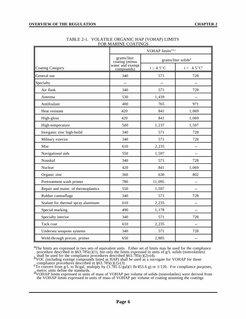
OVERVIEW OF THE REGULATION CHAPTER 2
Page 6
TABLE 2-1. VOLATILE ORGANIC HAP (VOHAP) LIMITS FOR MARINE COATINGS
Coating Category
VOHAP limitsa,b,c
grams/litercoating (minus
water and exemptcompounds)
grams/liter solidsd
t $ 4.5EC t < 4.5ECe
General use 340 571 728
Specialty -- -- --
Air flask 340 571 728
Antenna 530 1,439 --
Antifoulant 400 765 971
Heat resistant 420 841 1,069
High-gloss 420 841 1,069
High-temperature 500 1,237 1,597
Inorganic zinc high-build 340 571 728
Military exterior 340 571 728
Mist 610 2,235 --
Navigational aids 550 1,597 --
Nonskid 340 571 728
Nuclear 420 841 1,069
Organic zinc 360 630 802
Pretreatment wash primer 780 11,095 --
Repair and maint. of thermoplastics 550 1,597 --
Rubber camouflage 340 571 728
Sealant for thermal spray aluminum 610 2,235 --
Special marking 490 1,178 --
Specialty interior 340 571 728
Tack coat 610 2,235 --
Undersea weapons systems 340 571 728
Weld-through precon. primer 650 2,885 --
The limits are expressed in two sets of equivalent units. Either set of limits may be used for the complianceaprocedure described in §63.785(c)(1), but only the limits expressed in units of g/L solids (nonvolatiles)shall be used for the compliance procedures described §63.785(c)(2)-(4).VOC (including exempt compounds listed as HAP) shall be used as a surrogate for VOHAP for thosebcompliance procedures described in §63.785(c)(1)-(3).To convert from g/L to lb/gal, multiply by (3.785 L/gal)(1 lb/453.6 g) or 1/120. For compliance purposes,cmetric units define the standards.VOHAP limits expressed in units of mass of VOHAP per volume of solids (nonvolatiles) were derived fromdthe VOHAP limits expressed in units of mass of VOHAP per volume of coating assuming the coatings

CHAPTER 2 OVERVIEW OF THE REGULATION
Page 7
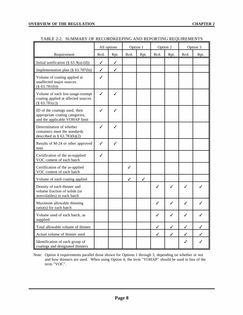
OVERVIEW OF THE REGULATION CHAPTER 2
Page 8
TABLE 2-2. SUMMARY OF RECORDKEEPING AND REPORTING REQUIREMENTS
Requirement
All options Option 1 Option 2 Option 3
Rcd. Rpt. Rcd. Rpt. Rcd. Rpt. Rcd. Rpt.
Initial notification (§ 63.9(a)-(d)) T T
Implementation plan (§ 63.787(b)) T T
Volume of coating applied at unaffected major sources(§ 63.781(b))
T
Volume of each low-usage-exemptcoating applied at affected sources(§ 63.781(c))
T T
ID of the coatings used, theirappropriate coating categories,and the applicable VOHAP limit
T T
Determination of whethercontainers meet the standardsdescribed in § 63.783(b)(2)
T T
Results of M-24 or other approvedtests
T T
Certification of the as-suppliedVOC content of each batch
T
Certification of the as-appliedVOC content of each batch
T
Volume of each coating applied T T
Density of each thinner andvolume fraction of solids (ornonvolatiles) in each batch
T T T T
Maximum allowable thinningratio(s) for each batch
T T T T
Volume used of each batch, assupplied
T T T T
Total allowable volume of thinner T T T T
Actual volume of thinner used T T T T
Identification of each group ofcoatings and designated thinners
T T
Note: Option 4 requirements parallel those shown for Options 1 through 3, depending on whether or notand how thinners are used. When using Option 4, the term "VOHAP" should be used in lieu of theterm "VOC".
CHAPTER 2 OVERVIEW OF THE REGULATION
Page 9
OVERVIEW OF THE REGULATION CHAPTER 2
Page 10
Page 11
CHAPTER 3
DOES THIS REGULATION APPLY TO ME?
APPLICABILITY OF THE REGULATION
The shipbuilding NESHAP is applicable toany major source of HAP emissions using more
than 1,000 liters of marine coatings annually.The actual and potential emissions of HAP source having surface coating operations with lessmaterials from most shipyards are substantially than 1,000 liters annual marine coating usageless than the major source cutoff limits [i.e., does not have to comply with the MACT
9.1 Mg/yr (10 tons/yr) of any single HAP, or standard. This provision gives relief to a source22.8 Mg/yr (25 tons/yr) of all HAP combined]. that qualifies as a major source because ofTo determine the applicability of this regulation activities other than shipbuilding/repair surfaceto your facility, you must determine whether the coating operations. However, the source is
plant site as a whole is a major source. A formal required to keep records of the volume of coatingHAP emissions inventory should be used to used in a year.determine if total potential HAP emissions fromall HAP emission sources at the plant site meets
the definition of a major source. This inventoryshould include all activities resulting in HAPemissions (whether shipbuilding/repair related ornot).
Existing major sources may switch to"synthetic area source" status by obtaining and
complying with an enforceable limit on theirpotential to emit prior to the "compliance date" ofthe regulation. The "compliance date" for thisregulation is December 16, 1997. New major
sources are required to comply with the NESHAPrequirements upon start up or the promulgationdate, whichever is later. If your facility withpotential HAP emissions greater than the cutoff
limit(s) has not obtained enforceable limits on itspotential to emit by the compliance date, and hasnot complied with the NESHAP requirements,you will be in violation of the NESHAP. All
sources that are major sources for HAP on thecompliance date are required to comply
permanently with the NESHAP to ensure that themaximum achievable reductions in toxic
emissions are achieved and maintained.
Are there any small usage provisions? Any
How many facilities are affected and whereare they located? The EPA estimates that there
are about 437 shipbuilding and ship repairfacilities (i.e., shipyards) nationwide. Of theestimated 437 shipyards, 35 are estimated to bemajor sources of HAP emissions. Figure 3-1 and
Table 3-1 show the approximate distribution ofthe facilities by State. Appendix C lists theknown facilities that are believed to be affectedby this regulation.
If a major source facility has several
painting operations and only some of thoseoperations exceed the minimum 1,000 liters
annual marine coating usage, is the shipbuildingNESHAP applicable? The shipbuilding
NESHAP is applicable to any major source ofHAP (and all associated operations or processsteps) that has total marine coating usage greaterthan the 1,000 liter cutoff. The cutoff was
intended to minimize the recordkeeping andreporting burden for those facilities doing
DOES THIS REGULATION APPLY TO ME? CHAPTER 3
Page 12
Fig
ure
3-1.
437
act
ive
U.S
. sh
ipbu
ildin
g fa
cilit
ies
(Aug
ust 1
991)
.
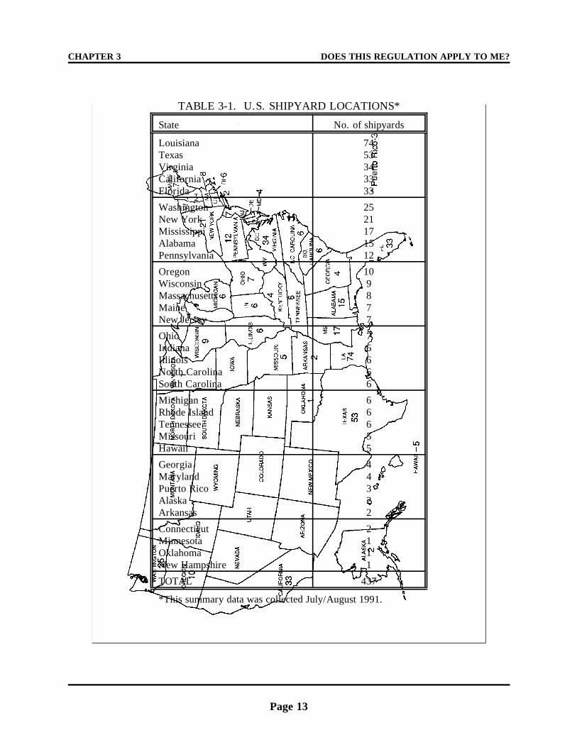
CHAPTER 3 DOES THIS REGULATION APPLY TO ME?
Page 13
TABLE 3-1. U.S. SHIPYARD LOCATIONS*
State No. of shipyards
LouisianaTexasVirginiaCaliforniaFlorida
7453343333
WashingtonNew YorkMississippiAlabamaPennsylvania
2521171512
OregonWisconsinMassachusettsMaineNew Jersey
109877
OhioIndianaIllinoisNorth CarolinaSouth Carolina
76666
MichiganRhode IslandTennesseeMissouriHawaii
66655
GeorgiaMarylandPuerto RicoAlaskaArkansas
44322
ConnecticutMinnesotaOklahomaNew Hampshire
2111
TOTAL 437
*This summary data was collected July/August 1991.
DOES THIS REGULATION APPLY TO ME? CHAPTER 3
Page 14
minimal or touch-up painting with marinecoatings.
If a ship is docked in a major sourcefacility, are any painting activities conducted by
the ship's crew covered by the regulation? Allactivities conducted within the boundaries of theshipyard must be accounted for, are subject to the
requirements of the regulation, and are theresponsibility of the shipyard owner/operator.When the Agency collected coatings and solventusage information from the industry, there was no
differentiation made regarding who was applyingthe various coatings and/or solvents.
What about shipyard painting operations oractivities that are conducted away from the
actual land-based facilities (i.e., downstream or"down the river")? Some determination would
have to be made regarding how far into the waterthe shipyard's boundaries extend. As initialguidance on this issue, we would recommend thatsuch activities be considered the same as other
painting activities and subject to the samerequirements.
If a shipyard company uses (leases)facilities owned by the State or Port Authority,
who is responsible for determining applicability?The owner or operator of the "affected source"should conduct an emissions inventory to
determine major source status based on aggregateair emissions of all HAP material. If it isdetermined that the facility is a major source, anydetails involving compliance demonstration
and/or reporting would have to be worked withthe appropriate enforcement agency.
RULE OF THUMB - RED FLAG ALERTS
If a shipyard answers yes to one or moreof the following questions it would suggest thata more in-depth review would be appropriate todetermine if the facility is subject to the
NESHAP.
1. Did your shipyard use in the last year
or does it anticipate using in the current year75,000 or more liters of paints and solvents?
2. Did your shipyard paint in the lastyear, or does it anticipate painting in thecurrent year 10 or more ships?
3. Did your shipyard paint in the last yearor does it anticipate painting in the current yearmore than 140,000 sq.meters of ship or vessel
surfaces?
4. Did your shipyard's estimating
department allocate for its paint shops duringthe last year or does it anticipate allocating inthe current year more than 6000 manhours ofpainting?
5. Did your shipyard generate and list ona hazardous waste manifest form in the last year
more than 15,000 liters of waste solvent?
Page 15
CHAPTER 4
WHAT DO I NEED TO DO TO COMPLY?
OVERVIEW
The following four principles should befollowed to comply with all requirements of theregulation:
1. Buy/Use only compliant coatings;
2. Do not thin any coating beyond theassociated maximum allowable thinningratio;
3. Use good work practices when handlingor transferring coatings, solvents, and/or resulting wastes; and
4. Follow all recordkeeping and reportingrequirements.
COATING COMPLIANCE OPTIONS
Because different shipyards track coatingand solvent usage in various ways, fourcompliance options were developed and
included in the regulation. Shipyards canchoose one or more (and any combination of)compliance options to demonstrate compliancein their monthly records and semiannual
compliance report. Options 1-3 are based onVOC being used as a surrogate for VOHAP.
• Option 1: Coatings to which thinningsolvent will not be added--If you neverthin coating prior to application, you willprobably want to choose option 1, which is
the most straightforward and leastburdensome in terms of recordkeeping andreporting requirements. Compliance isdetermined on a coating-by-coating basis.
• Option 2: Coatings to which thinningsolvent will be added - coating-by-coatingcompliance--Should be used when coatingsare thinned and you want to determine
compliance on a coating-by-coating basis.
• Option 3: Coatings to which the same
thinning solvent will be added - groupcompliance --Similar to Option 2, with theexception that compliance is demonstratedfor a group of coatings that are "grouped"
by thinner type.
• Option 4: Demonstration of compliance
through an alternative test method--Involves demonstration of complianceusing an alternative test method thatmeasures VOHAP content of a coating
rather than VOC content as in options 1through 3. Similar/parallel options tothose under 1 through 3 are implied underoption 4. (See Figure 4-1.)
Additional detail on these options is provided inChapter 5.
Is averaging allowed? No. For purposes
of complying with the NESHAP, no marinecoating with a VOHAP content exceeding theapplicable limit in Table 2-1 can be applied. The issue of averaging was considered during
the development of the NESHAP, and averagelimits were proposed to industry representativesas part of the regulatory alternatives evaluatedprior to proposal. (The average limits were
significantly lower than the maximum never-to-be-exceeded limits.) Industry, as representedby those participants in the meetings held with
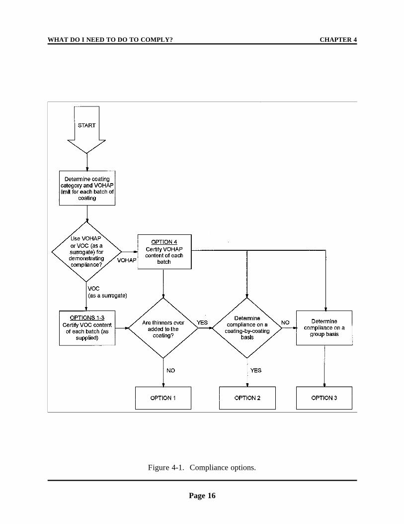
WHAT DO I NEED TO DO TO COMPLY? CHAPTER 4
Page 16
Figure 4-1. Compliance options.
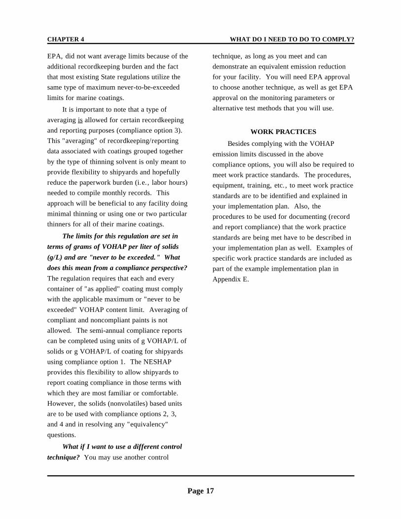
CHAPTER 4 WHAT DO I NEED TO DO TO COMPLY?
Page 17
EPA, did not want average limits because of the technique, as long as you meet and canadditional recordkeeping burden and the fact demonstrate an equivalent emission reductionthat most existing State regulations utilize the for your facility. You will need EPA approvalsame type of maximum never-to-be-exceeded to choose another technique, as well as get EPA
limits for marine coatings. approval on the monitoring parameters or
It is important to note that a type of
averaging is allowed for certain recordkeepingand reporting purposes (compliance option 3). This "averaging" of recordkeeping/reportingdata associated with coatings grouped together
by the type of thinning solvent is only meant toprovide flexibility to shipyards and hopefullyreduce the paperwork burden (i.e., labor hours)needed to compile monthly records. This
approach will be beneficial to any facility doingminimal thinning or using one or two particularthinners for all of their marine coatings.
The limits for this regulation are set interms of grams of VOHAP per liter of solids
(g/L) and are "never to be exceeded." Whatdoes this mean from a compliance perspective?
The regulation requires that each and everycontainer of "as applied" coating must complywith the applicable maximum or "never to be
exceeded" VOHAP content limit. Averaging ofcompliant and noncompliant paints is notallowed. The semi-annual compliance reportscan be completed using units of g VOHAP/L of
solids or g VOHAP/L of coating for shipyardsusing compliance option 1. The NESHAPprovides this flexibility to allow shipyards toreport coating compliance in those terms with
which they are most familiar or comfortable. However, the solids (nonvolatiles) based unitsare to be used with compliance options 2, 3,and 4 and in resolving any "equivalency"
questions.
What if I want to use a different control
technique? You may use another control
alternative test methods that you will use.
WORK PRACTICES
Besides complying with the VOHAP
emission limits discussed in the abovecompliance options, you will also be required tomeet work practice standards. The procedures,equipment, training, etc., to meet work practice
standards are to be identified and explained inyour implementation plan. Also, theprocedures to be used for documenting (recordand report compliance) that the work practice
standards are being met have to be described inyour implementation plan as well. Examples ofspecific work practice standards are included aspart of the example implementation plan in
Appendix E.
WHAT DO I NEED TO DO TO COMPLY? CHAPTER 4
Page 18
THIS PAGE INTENTIONALLY LEFT BLANK
Page 19
CHAPTER 5
HOW WILL I DEMONSTRATE COMPLIANCE?
Once you have selected which compliance
option(s) you intend to use (documented in yourimplementation plan), you have until the 15thday of each calendar month to compile therequired information to demonstrate compliance
for the previous month. Figure 5-1
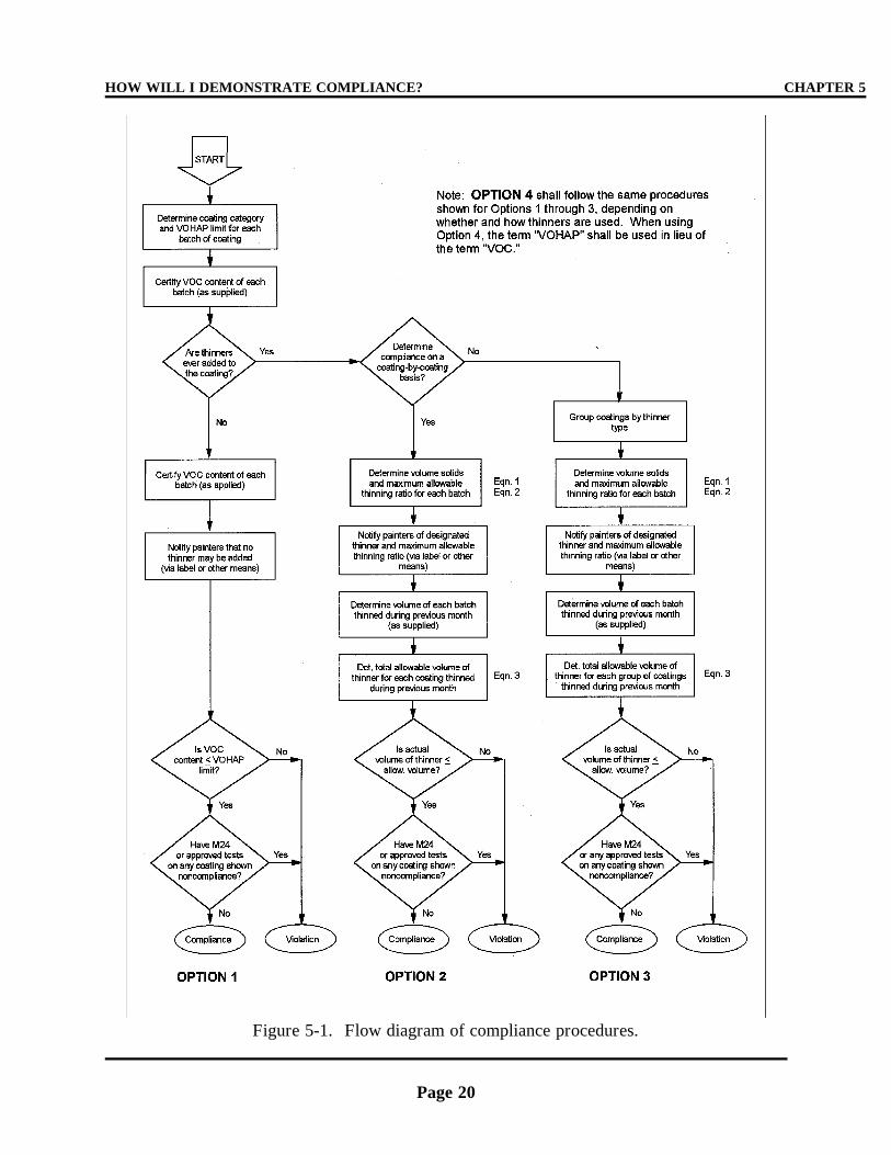
HOW WILL I DEMONSTRATE COMPLIANCE? CHAPTER 5
Page 20
Figure 5-1. Flow diagram of compliance procedures.
CHAPTER 5 HOW WILL I DEMONSTRATE COMPLIANCE?
Page 21
provides a flow diagram of all four complianceprocedures and Table 5-1
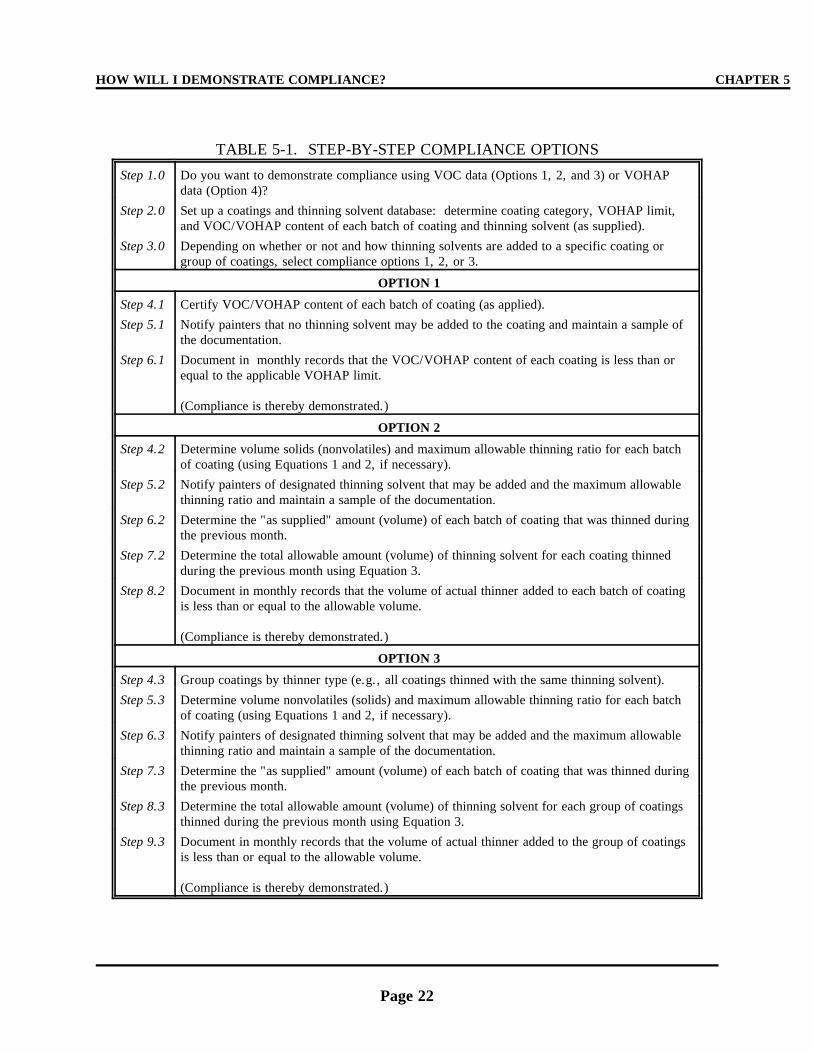
HOW WILL I DEMONSTRATE COMPLIANCE? CHAPTER 5
Page 22
TABLE 5-1. STEP-BY-STEP COMPLIANCE OPTIONS
Step 1.0 Do you want to demonstrate compliance using VOC data (Options 1, 2, and 3) or VOHAPdata (Option 4)?
Step 2.0 Set up a coatings and thinning solvent database: determine coating category, VOHAP limit,and VOC/VOHAP content of each batch of coating and thinning solvent (as supplied).
Step 3.0 Depending on whether or not and how thinning solvents are added to a specific coating orgroup of coatings, select compliance options 1, 2, or 3.
OPTION 1
Step 4.1 Certify VOC/VOHAP content of each batch of coating (as applied).
Step 5.1 Notify painters that no thinning solvent may be added to the coating and maintain a sample ofthe documentation.
Step 6.1 Document in monthly records that the VOC/VOHAP content of each coating is less than orequal to the applicable VOHAP limit.
(Compliance is thereby demonstrated.)
OPTION 2
Step 4.2 Determine volume solids (nonvolatiles) and maximum allowable thinning ratio for each batchof coating (using Equations 1 and 2, if necessary).
Step 5.2 Notify painters of designated thinning solvent that may be added and the maximum allowablethinning ratio and maintain a sample of the documentation.
Step 6.2 Determine the "as supplied" amount (volume) of each batch of coating that was thinned duringthe previous month.
Step 7.2 Determine the total allowable amount (volume) of thinning solvent for each coating thinnedduring the previous month using Equation 3.
Step 8.2 Document in monthly records that the volume of actual thinner added to each batch of coatingis less than or equal to the allowable volume.
(Compliance is thereby demonstrated.)
OPTION 3
Step 4.3 Group coatings by thinner type (e.g., all coatings thinned with the same thinning solvent).
Step 5.3 Determine volume nonvolatiles (solids) and maximum allowable thinning ratio for each batchof coating (using Equations 1 and 2, if necessary).
Step 6.3 Notify painters of designated thinning solvent that may be added and the maximum allowablethinning ratio and maintain a sample of the documentation.
Step 7.3 Determine the "as supplied" amount (volume) of each batch of coating that was thinned duringthe previous month.
Step 8.3 Determine the total allowable amount (volume) of thinning solvent for each group of coatingsthinned during the previous month using Equation 3.
Step 9.3 Document in monthly records that the volume of actual thinner added to the group of coatingsis less than or equal to the allowable volume.
(Compliance is thereby demonstrated.)
CHAPTER 5 HOW WILL I DEMONSTRATE COMPLIANCE?
Page 23
gives step-by-step instructions fordemonstrating compliance using each of thecompliance options. The required informationvaries slightly, depending on the selected
compliance option, but generally involvescertifying the total amount of each type (i.e.,category) of coating applied during the monthcompiled with the applicable VOHAP limit in
Table 2-1.
The "certification" of each coating is the
key to demonstrating compliance. Figure 5-2
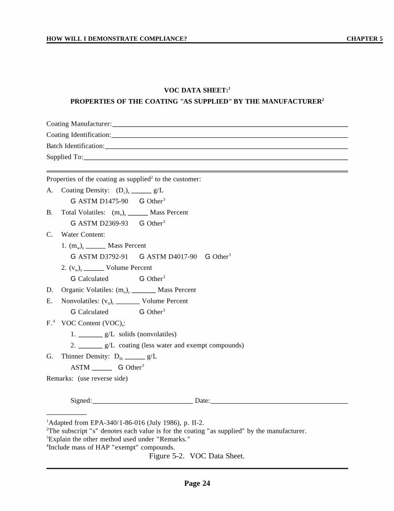
HOW WILL I DEMONSTRATE COMPLIANCE? CHAPTER 5
Page 24
VOC DATA SHEET:1
PROPERTIES OF THE COATING "AS SUPPLIED" BY THE MANUFACTURER2
Coating Manufacturer:
Coating Identification:
Batch Identification:
Supplied To:
Properties of the coating as supplied to the customer:2
A. Coating Density: (D ) g/Lc s
G ASTM D1475-90 G Other3
B. Total Volatiles: (m ) Mass Percentv s
G ASTM D2369-93 G Other3
C. Water Content:
1. (m ) Mass Percentw s
G ASTM D3792-91 G ASTM D4017-90 G Other3
2. (v ) Volume Percentw s
G Calculated G Other3
D. Organic Volatiles: (m ) Mass Percento s
E. Nonvolatiles: (v ) Volume Percentn s
G Calculated G Other3
F. VOC Content (VOC) : 4s
1. g/L solids (nonvolatiles)
2. g/L coating (less water and exempt compounds)
G. Thinner Density: D g/Lth
ASTM G Other3
Remarks: (use reverse side)
Signed: Date:
Adapted from EPA-340/1-86-016 (July 1986), p. II-2.1
The subscript "s" denotes each value is for the coating "as supplied" by the manufacturer.2
Explain the other method used under "Remarks."3
Include mass of HAP "exempt" compounds.4
Figure 5-2. VOC Data Sheet.
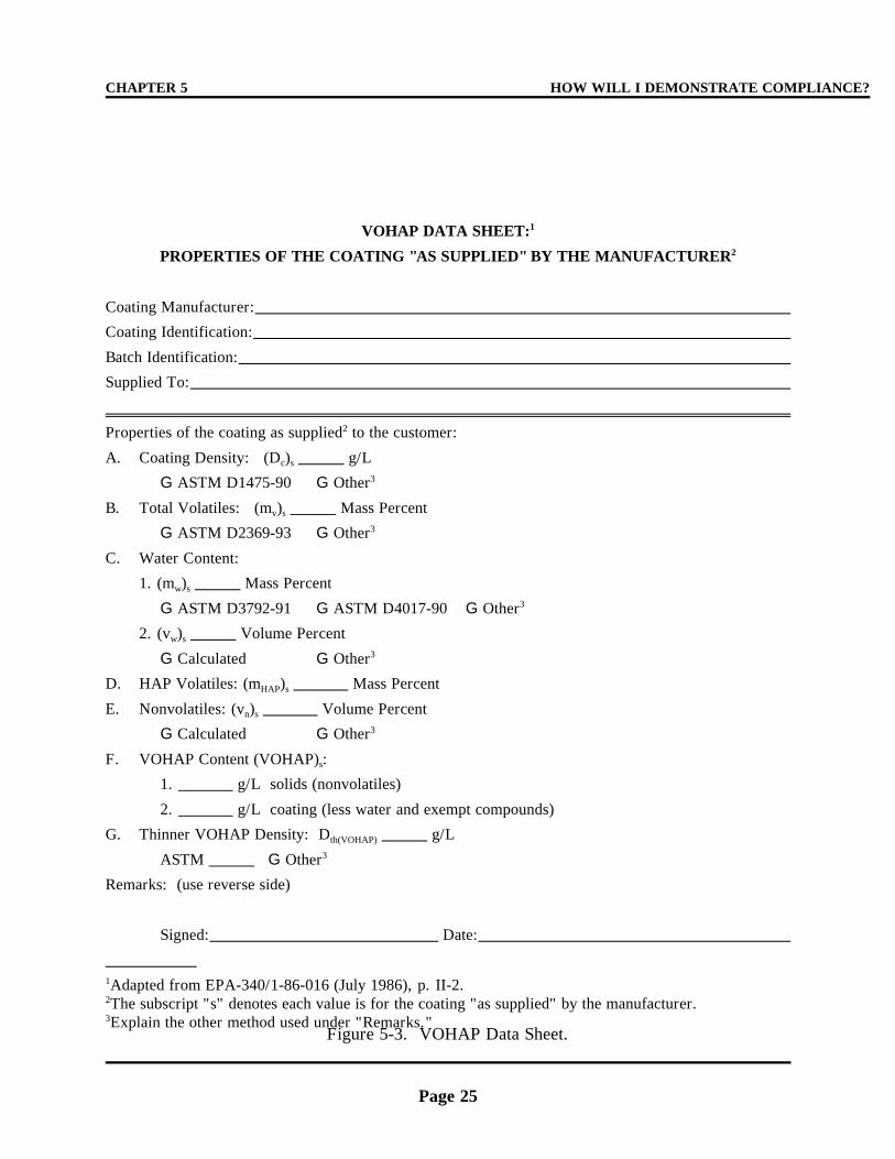
CHAPTER 5 HOW WILL I DEMONSTRATE COMPLIANCE?
Page 25
VOHAP DATA SHEET:1
PROPERTIES OF THE COATING "AS SUPPLIED" BY THE MANUFACTURER2
Coating Manufacturer:
Coating Identification:
Batch Identification:
Supplied To:
Properties of the coating as supplied to the customer:2
A. Coating Density: (D ) g/Lc s
G ASTM D1475-90 G Other3
B. Total Volatiles: (m ) Mass Percentv s
G ASTM D2369-93 G Other3
C. Water Content:
1. (m ) Mass Percentw s
G ASTM D3792-91 G ASTM D4017-90 G Other3
2. (v ) Volume Percentw s
G Calculated G Other3
D. HAP Volatiles: (m ) Mass PercentHAP s
E. Nonvolatiles: (v ) Volume Percentn s
G Calculated G Other3
F. VOHAP Content (VOHAP) : s
1. g/L solids (nonvolatiles)
2. g/L coating (less water and exempt compounds)
G. Thinner VOHAP Density: D g/Lth(VOHAP)
ASTM G Other3
Remarks: (use reverse side)
Signed: Date:
Adapted from EPA-340/1-86-016 (July 1986), p. II-2.1
The subscript "s" denotes each value is for the coating "as supplied" by the manufacturer.2
Explain the other method used under "Remarks."3
Figure 5-3. VOHAP Data Sheet.
HOW WILL I DEMONSTRATE COMPLIANCE? CHAPTER 5
Page 26
can be used for certifying the VOC content of aspecific coating, and Figure 5-3 can be used forcertifying the VOHAP content of a specificcoating. Other forms may be used to certify
either the VOC or VOHAP content of a marinecoating (see examples in Appendix E) and itshould be noted that the majority of the workassociated with the certification and compliance
demonstration needs to be done once thecoatings are ordered or received by theshipyard. Many of the coatings will be usedrepeatedly and having a good database of
coating compliance certification informationwill greatly simplify the monthly complianceburden.
If thinning solvents are sometimes orroutinely added to coatings prior to application,there are equations to be used
CHAPTER 5 HOW WILL I DEMONSTRATE COMPLIANCE?
Page 27
(see § 3.785(c)(2)) to calculate the maximum
allowable thinning ratio and the total allowablevolume of thinner. Once again, you can saveyourself a lot of time by collecting the relevantcoating and solvent data prior to the actual
application in the field. Similar provisions areincluded for cold weather (temperatures<4.5 EC) conditions, as well as separateVOHAP limits (see Table 2-1).
The source has an existing inventory of
paints that may exceed the NESHAP limits. Can the source finish its inventory after the
compliance date? Can the source enter intoconsent orders or have a grace period to use it
up? The other alternative would be to disposeof it as hazardous waste. In light of the recent
direct final regulation (June 18, 1996), whichextended the compliance date from December16, 1996 to December 16, 1997, the EPAbelieves there should be no reason to have
noncompliant coatings in inventory at anyshipyard on the new compliance date. Industryrepresentatives and trade associations haveworked with the EPA for the past 5 years in
developing the NESHAP and the CTG and arewell aware of the limits. The coatingmanufacturers and the National Paint andCoatings Association (NPCA) are similarly
informed.
HOW WILL I DEMONSTRATE COMPLIANCE? CHAPTER 5
Page 28
THIS PAGE INTENTIONALLY LEFT BLANK
Page 29
CHAPTER 6
WHAT RECORDKEEPING AND REPORTING WILL INEED TO DO?
RECORDKEEPING RECORDKEEPING AND REPORTING
This regulation requires that you keep
records to document your compliance statuswith the regulation. It is recommended thatsomeone at each facility be identified tomaintain all NESHAP compliance
recordkeeping information as required for eachoption used during the reporting periods. These records must be maintained for 5 years. Many, but not all, recordkeeping items are
reported. The recordkeeping requirements aresummarized in Table 2-2.
REPORTING
You must submit all reports to the
Administrator before the 60th day followingcompletion of each 6-month period after thecompliance date. The "Administrator" is theappropriate Regional Office of the U. S.
Environmental Protection Agency (as listed inTable 10-1 of this guidebook) or the delegatedState or local authority. You may contact theappropriate EPA Regional Office to identify
those State or local agencies with delegatedauthority. The required reports may be sent byU.S. Mail, fax, or by another courier (includingelectronic submission). The reporting require-
ments are summarized in Table 2-2. Forexisting sources, the first six month complianceperiod ends June 16, 1998, and the associatedcompliance report is due August 16, 1998.
REQUIREMENTS
For both recordkeeping and reporting,
specific requirements vary according to whichparticular compliance option you choose. (These compliance options are detailed inChapter 4.) Regardless of which option you
choose, you must record and, in most cases,report the following items:
• Initial notifications
If your source had an initial start-update before December 15, 1996, (thiswould include all affected existingfacilities), you should have submitted
an initial notification by June 15, 1996. Any new source (with an initial start-update on or after December 15, 1996)must submit an initial notification
6 months prior to start-up. (SeeAppendix D.)
• Implementation Plan
Existing sources must submit an imple-mentation plan by December 16, 1996. A sample implementation plan isincluded as Appendix E. The sample
implementation plan is only anexample; you can use any format aslong as your implementation planprovides the following information:
WHAT RECORDKEEPING AND REPORTING WILL I NEED TO DO? CHAPTER 6
Page 30
(1) Coating Compliance Procedures
(2) Recordkeeping Procedures. You
must include the procedures formaintaining all required records,including the procedures forgathering necessary data and
making calculations
(3) Transfer, Handling, and Storage
Procedures. You must include theprocedures for ensuringcompliance with the requirementsof the regulation as discussed in
Chapter 5
• Monthly records
(1) Volume of each low-usage-exempt
coating applied (by month)
(2) Identification of the coatings used,
their EPA categories, and VOHAPlimits
(3) Results of Method 24 or other ap-proved measurements onindividual containers
(4) Certification of as-supplied VOCcontent for each batch of coating* (See examples in Appendix F)
Additional recordkeeping and reportingrequirements depend on your facility's specific
compliance procedures. (These procedures aredescribed in Chapter 5 of this guidebook.) Thefollowing discussion presents theserequirements according to the specific compli-
ance procedures.
Option 1 - No Thinning Solvents Added
If your facility does not add any thinning
solvents to coatings, you may opt to useoption 1. If you choose this option, youmust record the following information:
*Must be recorded, but not reported.
CHAPTER 6 WHAT RECORDKEEPING AND REPORTING WILL I NEED TO DO?
Page 31
• Certification of the as-applied VOC • Maximum allowable thinner ratio forcontent of each batch of coating (which each batch, including calculations *is the same as the as-supplied VOCcontent)
• The volume of each coating applied*
• Compliance violations, if applicable thinners *
Option 2 - Coating-By-Coating Compliance
If you choose this type of compliance, youmust record the following information foreach coating for each month:
• Designated thinner for the coating andits density
• Volume fraction of solids (nonvolatiles)for each batch of the coating, includingcalculations *
• Maximum allowable thinning ratio foreach batch of the coating, including
calculations *
• Cold weather dates and times, below than the VOC surrogate used under
4.5EC (if cold weather VOHAP content Options 1-3, you must record and reportlimits are used) * the Administrator-approved VOHAP test
• Volume of each batch of the coatingapplied *
• Total allowable volume of thinner,including calculations *
• Actual volume of thinner used
• Compliance violations, if applicable
Option 3 - Group Compliance
If you choose this type of compliance, youmust record the following information:
• Designated thinner for the group ofcoatings and its density
• Mass fraction and volume fraction ofsolids (nonvolatiles) for each batch of
each coating in the group, includingcalculations *
• Cold weather dates and times, below4.5EC *
• Identification of coating groups and
• Volume applied of each batch of eachcoating in the group *
• Total allowable volume of thinner,including calculations *
• Actual volume of thinner used*
• Compliance violations, if applicable
Option 4 - Alternative Test Method
Compliance may be demonstrated throughan alternative (i.e., other than EPA
Method 24) test method. If you choose analternative test method where complianceis based on actual VOHAP content, rather
method or certification procedure. Theother recordkeeping and reporting
requirements are identical to those ofOptions 1, 2, or 3, depending on if andhow thinners are used.
Method 311 - Analysis of Hazardous AirPollutant Compounds in Paints and Coatings byDirect Injection into a Gas Chromatograph was
developed by EPA as a result of the WoodFurniture (Surface Coating) NESHAP. However, any alternative test method must meetthe specified accuracy limits for sensitivity,
duplicates, repeatability, and reproducibilitycoefficient of variation described inSection 63.786 Test methods and Procedures ofthe final regulation (see Appendix A).
WHAT RECORDKEEPING AND REPORTING WILL I NEED TO DO? CHAPTER 6
Page 32
(Note: When using Option 4, the term • All quality assurance activities per-"VOHAP" should be used instead of the formed on any monitoring procedures.term "VOC" since compliance is to bedemonstrated using actual VOHAP
content--see Figure 5-1 and Table 5-1.)
What if a violation in the standard occurs?
If you detect a violation of the standards,
you must record additional information for theremainder of the reporting period during whichthe violation occurred. Your violation may becovered by a Federally-approved exemption
(e.g., a promulgated exemption from an emis-sion limitation or standard published in theFederal Register). If it is, you must report thefollowing information:
• A summary of the number and durationof the violations, classified by reason
• A summary of the number and totalduration of incidents in which the
monitoring procedures did not operatesmoothly or produced data that wasinaccurate, classified by reason.
• The compliance status on the last day ofthe reporting period and information onwhether compliance was continuous or
interrupted during the reporting period.
For other violations, a federally-approved ex-
emption may not apply to the violation. Inthese instances, you must report the followinginformation:
• The magnitude of each violation
• The reason for each violation
• A description of the corrective action
taken for each violation, which shouldinclude actions taken to minimize eachviolation and the action taken toprevent reoccurrences
There has been some confusion regarding theinitial notification and the implementation
plan for complying with the shipbuildingNESHAP. When are they due? When the final
regulation was published in the Federal Registeron December 15, 1995 (see Appendix A), boththe initial notification and implementation planwere to be submitted by June 15, 1996.
However, the direct final regulation publishedon June 18, 1996 in the Federal Registerextended the due date for submitting yourimplementation plan until December 16, 1996,
and extended the compliance date to December16, 1997. It was EPA's intent to only extendthe due date for submitting the implementationplan and extend the compliance date. Initial
notifications were never an issue and were dueJune 13, 1996.
Page 33
CHAPTER 7
WHAT ARE MY POLLUTION PREVENTION OPTIONS?
What is Pollution Prevention? As stated inthe Pollution Prevention Act of 1990, Congress
has declared it to be the nation's policy that,wherever feasible, pollution should beprevented or reduced at the source. The Actstates that source reduction is more desirable
than waste management and pollution control. Source reduction is defined as any practice thatreduces the amount of any hazardous substanceentering the waste stream or otherwise released
into the environment (from a process) prior torecycling, treatment, or disposal. Therefore,you must also consider wastewater, hazardouswaste, and solid waste effects and regulations as
well as air pollutant emissions in selecting anymethod of control.
What are my options? This regulationallows for pollution prevention measures to beused when complying with the requirements of
the regulation. The entire regulation focuses onpollution prevention in that the marine coatinglimits are based on switching to lowerVOC/VOHAP coatings (alternatives are
allowed, but require special approval) and thework practice standards are intended to reduceevaporative losses and prevent spills andaccidental emissions.
There are several potential pollutionprevention options for the shipbuilding and ship
repair industry, many of which can be includedas work practice standards in the facility-specific implementation plan.
These options include:
• More efficient application equipment
• Extensive operator training
• Reformulated marine coatings
• Recycling of cleaning solvents
• Alternative cleaning materials
• Containment around storage areas for
VOC/VOHAP-containing materials
Other pollution prevention measures
include (1) carefully handling and transferringall VOC/ VOHAP containing materials to andfrom containers, tanks, vats, vessels, and pipingsystems so that spills are minimized and (2)
closing all thinning solvent and waste containersthat hold any VOC/VOHAP unless adding orremoving materials from them.
WHAT ARE MY POLLUTION PREVENTION OPTIONS? CHAPTER 7
Page 34
THIS PAGE INTENTIONALLY LEFT BLANK
Page 35
CHAPTER 8
HOW DOES THIS REGULATION RELATE TO OTHER FEDERAL ANDSTATE OR LOCAL REQUIREMENTS?
PERMITTING
Will I need a State operating permit? Yes. Under title V, all major sources arerequired to obtain permits--no deferrals or
exemptions are allowed for these major sources.
Title V operating permit program
background. Title V of the CAA as amended in1990 requires the establishment of State-implemented operating permits programs withFederal oversight. Prior to the 1990 amend-
ments, sources were not required by Federallaw to obtain operating permits for sources ofair pollution emissions. However, many Statesissued their own operating permits to certain
sources. You may have been required to obtainan operating permit for your facility under aState permit program in the past. Now, allmajor sources are required to obtain a title V
operating permit.
Permit requirements in general. The
operating permit program will incorporate allapplicable Federal CAA regulationrequirements and any State or local governmentrequirements. Therefore, permit requirements
will be at least as stringent as requirementsmandated by the Federal CAA regulations (e.g.,the shipbuilding and ship repair NESHAP).
The basic format of operating permits isdetailed (codified) in part 70 of title 40 of theCode of Federal Regulations (40 CFR part 70).
Owners or operators of facilities subject toFederal CAA regulations will have to:
< submit a permit application;
< submit compliance plans and schedules;
< comply with all applicable air emission
limits and standards listed in the permit(e.g., the shipbuilding and ship repairNESHAP);
< conduct monitoring (if required),submit monitoring reports, and makesemi-annual certifications of the
source's compliance status;
< submit applications for any permit
modifications;
< submit applications for permit renewals
every 5 years; and
< pay a permit or emission fee.
Does my State have a permitting
program? All States must develop a title Voperating permits program. States wererequired to submit their permitting programs to
EPA for approval by November 15, 1993. Oneyear later, the EPA was to have approved theStates' permitting programs and authorized theStates to administer their programs. As of July
1996, approvals have been published in theFederal Register for 42 State and 56 localprograms; additionally, EPA has proposed toapprove another 4 State agency programs and
3 local agency programs. The EPA'sTechnology Transfer Network (TTN), anelectronic bulletin board system, has the lateststatus of permit program submittals and
approvals. (See Chapter 10 for instructions onhow to access the TTN.) You may also contactyour State or local air pollution control agency
HOW DOES THIS REGULATION RELATE TO OTHERFEDERAL AND STATE OR LOCAL REQUIREMENTS? CHAPTER 8
Page 36
for more information on the status of yourState's title V operating permit program.
When do I apply for my operating permit? Your deadline for submitting a title V operatingpermit application will depend on when your
State or local title V permitting program isapproved by the EPA. In general, yourapplication will be due within 12 months afterthe title V program approval date. However,
some State and local permitting authorities haveshorter deadlines. Once you have youroperating permit, it must be renewed or updatedat least every 5 years.
EPA's GENERAL PROVISIONS
On March 16, 1994, EPA published theGeneral Provisions for all regulations codifiedin part 63 (i.e., all NESHAP) of the Code of
Federal Regulations (CFR). These GeneralProvisions were published in the FederalRegister in volume 59, beginning onpage 12408. When a source becomes subject to
a regulation in part 63, it automatically issubject to the General Provisions as well. However, individual regulations in part 63 mayoverride part or all of the General Provisions.
In the case of this regulation, EPA has over-ridden some of the requirements of the GeneralProvisions. Table 1 of the shipbuilding In addition to air pollution regulations,regulation (located on page 64344 of the shipyard surface coating operations may also be
Federal Register text, see Appendix A) explains subject to wastewater and solid waste disposalin detail which sections apply and which regulations. Contact your State or local per-sections are overridden. mitting authority for more information.
STATE OR LOCAL MARINE
COATING REGULATIONS
State or local requirements that may haveaffected you prior to the new Federal regulationfor shipbuilding and ship repair continue toapply. The new Federal regulation is the
minimum emission control that is requirednationally. Some State and local agencies dorequire stricter limits. If the current State orlocal standard is less stringent than the Federal
regulation, the Federal regulation must be met.
The format of State or local standards may
be different also. For example, the CaliforniaAir Resources Board (CARB), the various airquality management districts in California, andthe State of Louisiana have marine coating
limits expressed in terms of mass (g) of VOCper volume (L) of coating less water andexempt compounds. State regulations typicallyrelate to VOC rather than VOHAP.
Accordingly, State rules may have shortercompliance periods (e.g., daily rather thanmonthly). The NESHAP was based primarilyon the marine coating limits in California, and
the solids- (nonvolatiles) based limits of theNESHAP are equivalent to those limitsexpressed in the California marine coatingregulation.
Page 37
CHAPTER 9
HOW MUCH WILL IT COST?
OVERVIEW
The cost of complying with the regulationwill typically involve additional material(coatings) and recordkeeping and reportingcosts. As summarized in Chapters 4 and 5, you
only have to use compliant coatings (which arereadily available in today's market) and goodwork practices to comply with the regulation. Compliant coatings may be more expensive
than the conventional coatings they replace. Inaddition, demonstrating compliance to theappropriate enforcement official will involvemore paperwork and labor to complete that
paperwork. Many of the larger (i.e., Tier I)shipyards have tracking systems currently inplace that will only have to be modified slightlyor not at all. Shipyards located in states such as
California and Louisiana that have beencomplying with similar requirements for severalyears should have minimal cost impacts as well.
In developing cost impacts of theregulation, EPA used model plants to analyzeseparate costs. Table 9-1 summarizes the costs
for each size and type of model shipyard. These results represent the original shipyardcosts to comply and were calculated as thedifference between before (baseline) and after
NESHAP costs. The average shipyard wasprojected to spend $58,000/yr to comply withthe regulation.
MATERIAL (COATING) COSTS
The net cost associated with switching tolower-VOHAP coatings was assumed to be the
sum of the additional cost of compliantcoatings, the savings associated with highersolids content, the savings associated withdecreased thinner usage. Costs were developed
for "baseline" (all coatings being usedcurrently) and for those coatings meeting theVOHAP limits in Table 2-1. The differencebetween the use of baseline and compliant
coatings is presented in Table 9-1.
For the impact analysis, it was assumed
that the total build of a lower-VOHAP coating(the dry film thickness) would equal that of theconventional counterpart, i.e., the total amountof solids (nonvolatiles) applied would remain
constant. Because lower-VOHAP solvent-bornecoatings contain more nonvolatiles (solids), thetotal volume of paint needed to coat a givenarea is less than for the conventional, lower-
solids coatings (assuming constant transferefficiency). The lower-VOHAP coatings,however, are more expensive on a dollar-per-unit volume basis.
In evaluating the use of lower-VOHAPsolvent-borne coatings, it was assumed that
lower-VOHAP coatings require the sameamount of thinning solvent, liter for liter, asconventional coatings. Because fewer liters oflower-VOHAP coatings are required (as a result
of their higher solids content), thinner usewould decrease. A decrease in the amount ofthinner used results in VOHAP emissionreductions and a cost savings.
HOW MUCH WILL IT COST? CHAPTER 9
Page 38
RECORDKEEPING AND REPORTING
Recordkeeping and reporting (R&R)practices are established by permit conditions,and in some instances, the requirements ofsection 313 of the Superfund Amendments and
Reauthorization Act of 1986 (SARA 313). Forthat reason, the cost of recordkeeping to complywith permit and SARA 313 requirements areconsidered as the baseline from which to
measure the incremental cost of this regulation. Complying with the NESHAP will require moreinvolved recordkeeping practices than thosenecessary at the baseline.
Recordkeeping and reporting costs are afunction of the equipment and labor required.
A computer (and software) will probably beused. Labor requirements include training, datarecording and analysis, and report preparation.
Most large and medium shipyards alreadymaintain records to comply with State or localpermits as well as SARA 313 requirements. It
has been assumed that the operations at thesefacilities are complex enough and the facilitiessophisticated enough that they already use acomputerized system for R&R.
The current reporting requirements for available control measures (BACM) for controllarge and medium yards (at baseline) are of VOC.
assumed to consist of an annual SARA 313report and an annual report of VOC emissions. To prepare these reports, it is assumed that thefacilities have adapted their central inventory
tracking system to record the quantity of eachpaint and thinner used at the yard. It is alsoassumed that this information is coupled with adata base in which the HAP and VOC contents
of each paint and thinner are stored. The totaltechnical labor devoted to recordkeeping andreporting for large and medium yards prior topromulgation of the NESHAP is estimated to be
159 hours per years (hr/yr). To comply withthe NESHAP it was assumed that no additionalequipment is required for any affected facility.
Most of the additional costs associatedwith the NESHAP will result from the highercosts of compliant coatings compared to those
being used currently. The recordkeeping andreporting burden only accounts forapproximately 25 percent of the total costs.
TOTAL COSTS
Table 9-1 summarizes the total industryannual costs resulting from implementing theNESHAP, which were estimated to be about$2.0 million. The average facility cost to
comply with the final regulation is estimated tobe $58,000/yr. These estimates presume thatall incremental environmental costs are imposedas a consequence of implementing MACT. In
fact, those shipyards located in nonattainmentareas (which is thought to include most of the35) will likely be required to bear essentiallythe same costs to meet State requirements for
limiting VOC emissions as the States imposerules based on EPA's recommendations on best
PERMITTING FEES
As discussed in Chapter 8, you may berequired by the regulation to obtain anoperating permit under title V of the CAA. If
so, you will be charged a permit or emission feeby your State or local permitting authoritywhen you apply for your title V permit. Thisfee will vary from State to State. For more
information on title V operating permit fees,contact your State or local permitting authorityor the EPA Regional Office for your State.
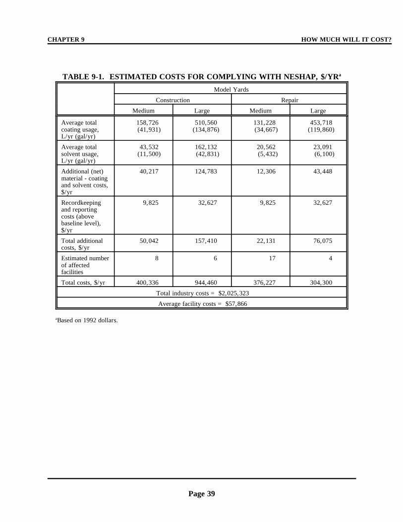
CHAPTER 9 HOW MUCH WILL IT COST?
Page 39
TABLE 9-1. ESTIMATED COSTS FOR COMPLYING WITH NESHAP, $/YRa
Model Yards
Construction Repair
Medium Large Medium Large
Average totalcoating usage,L/yr (gal/yr)
158,726(41,931)
510,560(134,876)
131,228(34,667)
453,718(119,860)
Average totalsolvent usage,L/yr (gal/yr)
43,532(11,500)
162,132(42,831)
20,562(5,432)
23,091(6,100)
Additional (net)material - coatingand solvent costs,$/yr
40,217 124,783 12,306 43,448
Recordkeepingand reportingcosts (abovebaseline level),$/yr
9,825 32,627 9,825 32,627
Total additionalcosts, $/yr
50,042 157,410 22,131 76,075
Estimated numberof affectedfacilities
8 6 17 4
Total costs, $/yr 400,336 944,460 376,227 304,300
Total industry costs = $2,025,323
Average facility costs = $57,866
Based on 1992 dollars. a
HOW MUCH WILL IT COST? CHAPTER 9
Page 40
THIS PAGE INTENTIONALLY LEFT BLANK
Page 41
CHAPTER 10
WHERE CAN I GO FOR MORE INFORMATION AND ASSISTANCE?
TELEPHONE CONTACTS OTHER EPA GUIDANCE MATERIALS
For more information on how to comply In developing this regulation, EPA haswith this regulation, please call: prepared other materials that provide more
F your State or local air pollution controlagency;
F your local, regional, or national tradeassociation;
F your State Small Business AssistanceProgram; or
F your State Small Business Ombudsman.
For information on your State Small BusinessAssistance Program contacts, call EPA'sControl Technology Center Hotline at (919)541-0800.
Also, for more information, you may callthe EPA Regional Office that serves your State
or territory. Table 10-1 lists the telephonenumbers of the 10 EPA Regional Offices andthe States and territories that they serve.
EPA's ELECTRONIC BULLETIN
BOARD SYSTEM
The EPA operates an electronic bulletinboard, the Technology Transfer Network or"TTN," which contains copies of preambles andregulations, background information
documents, policy memoranda, and otherguidance materials. You may access the TTNvia modem by dialing (919) 541-5742 or theInternet at http:\\ttnwww.rtpnc.epa.gov.
Assistance with the TTN is available by calling(919) 541-5384.
information on the technical aspects of the
regulation. These include:
< Surface Coating Operations at Ship-
building and Ship Repair Facilities--Background Information for ProposedStandards (Volume I).
EPA-453/R-93-030a. February 1994.
< National Emission Standards forHazardous Air Pollutants for Ship-building and Ship Repair Facilities(Surface Coating)--Background
Information for Final Standards.
EPA-453/R-95-016b. November 1995.
Copies of these reports are available throughEPA's Library Services Office (MD-35), U. S.
Environmental Protection Agency, ResearchTriangle Park, North Carolina 27711, (919)541-2777; on EPA's TTN; or, for a fee, fromthe National Technical Information Services,
5285 Port Royal Road, Springfield, Virginia 22161, (703) 487-4600.
Also, EPA has developed an informationalpamphlet which has summarized much of thegeneral information contained in thisguidebook. A copy of the pamphlet may be
obtained by contacting Dr. MohamedSerageldin of EPA's Emission StandardsDivision, Research Triangle Park, NorthCarolina. His telephone, fax, and email are
(919) 541-2379, (919) 541-5689, [email protected],respectively. You may also contact
WHERE CAN I GO FOR MOREINFORMATION AND ASSISTANCE? CHAPTER 10
Page 42
Ms. Suzanne Childress of EPA's Office ofEnforcement and Compliance Assurance(OECA), Mail Station 2223-A, 401 M Street,S.W., Washington, D.C. 20460. Her telephone
and fax numbers are (202) 564-7018 and (202)564-7018, respectively.

WHERE CAN I GO FOR MORECHAPTER 10 INFORMATION AND ASSISTANCE?
Page 43
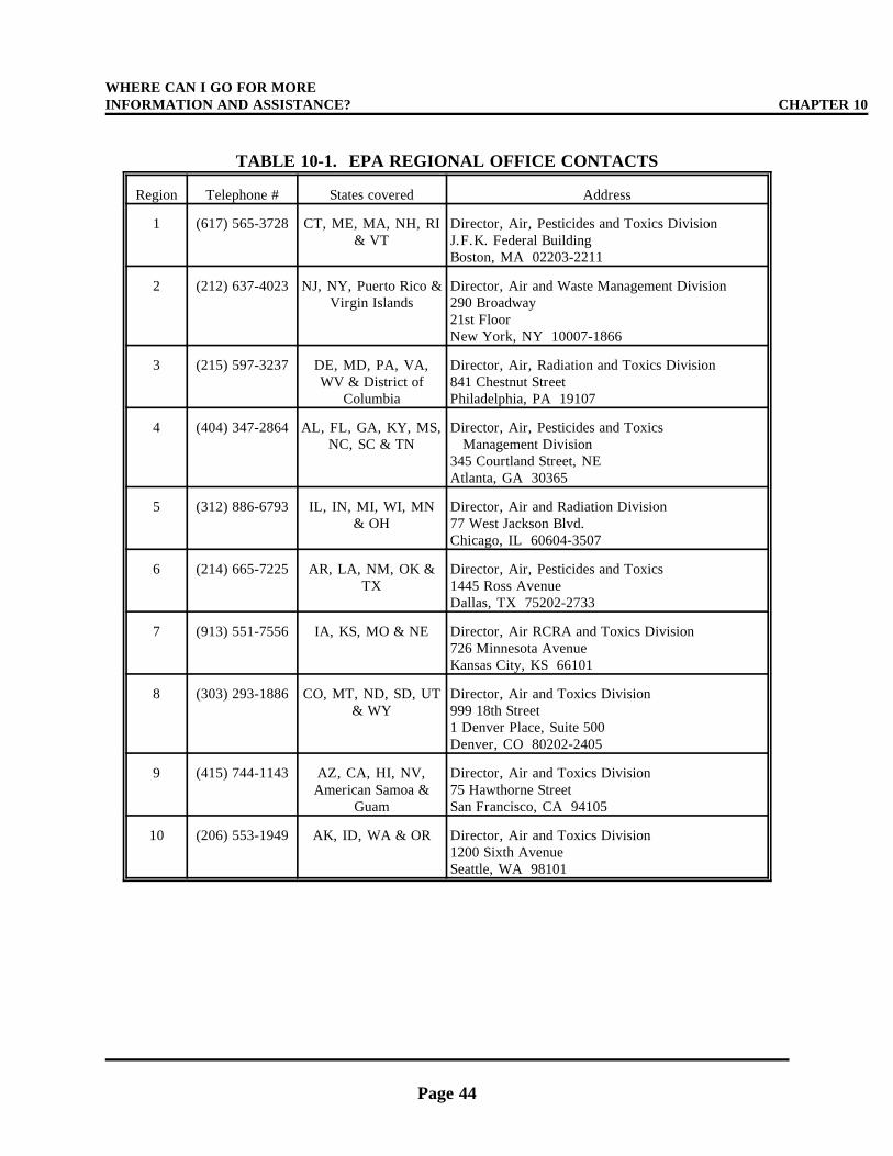
WHERE CAN I GO FOR MOREINFORMATION AND ASSISTANCE? CHAPTER 10
Page 44
TABLE 10-1. EPA REGIONAL OFFICE CONTACTS
Region Telephone # States covered Address
1 (617) 565-3728 CT, ME, MA, NH, RI& VT
Director, Air, Pesticides and Toxics DivisionJ.F.K. Federal BuildingBoston, MA 02203-2211
2 (212) 637-4023 NJ, NY, Puerto Rico &Virgin Islands
Director, Air and Waste Management Division290 Broadway21st FloorNew York, NY 10007-1866
3 (215) 597-3237 DE, MD, PA, VA,WV & District of
Columbia
Director, Air, Radiation and Toxics Division841 Chestnut StreetPhiladelphia, PA 19107
4 (404) 347-2864 AL, FL, GA, KY, MS,NC, SC & TN
Director, Air, Pesticides and Toxics Management Division345 Courtland Street, NEAtlanta, GA 30365
5 (312) 886-6793 IL, IN, MI, WI, MN& OH
Director, Air and Radiation Division77 West Jackson Blvd.Chicago, IL 60604-3507
6 (214) 665-7225 AR, LA, NM, OK &TX
Director, Air, Pesticides and Toxics1445 Ross AvenueDallas, TX 75202-2733
7 (913) 551-7556 IA, KS, MO & NE Director, Air RCRA and Toxics Division726 Minnesota AvenueKansas City, KS 66101
8 (303) 293-1886 CO, MT, ND, SD, UT& WY
Director, Air and Toxics Division999 18th Street1 Denver Place, Suite 500Denver, CO 80202-2405
9 (415) 744-1143 AZ, CA, HI, NV,American Samoa &
Guam
Director, Air and Toxics Division75 Hawthorne StreetSan Francisco, CA 94105
10 (206) 553-1949 AK, ID, WA & OR Director, Air and Toxics Division1200 Sixth AvenueSeattle, WA 98101
WHERE CAN I GO FOR MORECHAPTER 10 INFORMATION AND ASSISTANCE?
Page 45
WHERE CAN I GO FOR MOREINFORMATION AND ASSISTANCE? CHAPTER 10
Page 46
THIS PAGE INTENTIONALLY LEFT BLANK

Page A-1
APPENDIX A
FEDERAL REGISTER NOTICE:FINAL RULE AND DIRECT FINAL RULE

Page A-2
Page B-1
APPENDIX B
GLOSSARY OF TERMS
Terms used in the NESHAP and in this Guidebook are defined in the Clean Air Act (Act), or in
this section as follows:
Add-on control system means an air pollution control device such as a carbon absorber or
incinerator that reduces pollution in an air stream by destruction or removal prior to discharge to the
atmosphere.
Affected source means any shipbuilding or ship repair facility having surface coating operations
with a minimum 1,000 liters (L) (264 gallons [gal]) annual marine coating usage.
Air flask specialty coating means any special composition coating applied to interior surfaces of
high pressure breathing air flasks to provide corrosion resistance and that is certified safe for use with
breathing air supplies.
Antenna specialty coating means any coating applied to equipment through which electromagnetic
signals must pass for reception or transmission.
Antifoulant specialty coating means any coating that is applied to the underwater portion of a
vessel to prevent or reduce the attachment of biological organisms and that is registered with the EPA as
a pesticide under the Federal Insecticide, Fungicide, and Rodenticide Act.
As applied means the condition of a coating at the time of application to the substrate, including
any thinning solvent.
As supplied means the condition of a coating before any thinning, as sold and delivered by the
coating manufacturer to the user.
Batch means the product of an individual production run of a coating manufacturer's process. (A
batch may vary in composition from other batches of the same product.)
Bitumens mean black or brown materials that are soluble in carbon disulfide, which consist mainly
of hydrocarbons.
Bituminous resin coating means any coating that incorporates bitumens as a principal component
and is formulated primarily to be applied to a substrate or surface to resist ultraviolet radiation and/or
water.
Certify means, in reference to the volatile organic compound (VOC) content or volatile organic
hazardous air pollutant (VOHAP) content of a coating, to attest to the VOC content as determined
GLOSSARY OF TERMS APPENDIX B
Page B-2
through analysis by Method 24 of appendix A to part 60 of title 40 of the Code of Federal Regulations
(40 CFR 60) or through the use of forms and procedures outlined in Figure 5-2, or to attest to the
VOHAP content as determined through an EPA approved test method. In the case of conflicting results,
Method 24 of Appendix A to 40 CFR Part 60 shall take precedence over the forms and procedures
outlined in Figure 5-2 for the options in which VOC is used as a surrogate for VOHAP.
Coating means any material that can be applied as a thin layer to a substrate and which cures to
form a continuous solid film.
Cold-weather time period means any time during which the ambient temperature is below 4.5EC
(40EF) and coating is to be applied.
Container of coating means the container from which the coating is applied, including but not
limited to a bucket or pot.
Cure volatiles means reaction products that are emitted during the chemical reaction which takes
place in some coating films at the cure temperature. These emissions are other than those from the
solvents in the coating and may, in some cases, comprise a significant portion of total VOC and/or
VOHAP emissions.
Epoxy means any thermoset coating formed by reaction of an epoxy resin (i.e., a resin containing a
reactive epoxide with a curing agent).
Exempt compounds means specified organic compounds that are not considered VOC due to
negligible photochemical reactivity. Exempt compounds are specified in 40 CFR §51.100(s).
Facility means all contiguous or adjoining property that is under common ownership or control,
including properties that are separated only by a road or other public right-of-way.
General use coating means any coating that is not a specialty coating.
Hazardous air pollutant (HAP) means any air pollutant listed in or pursuant to Section 112(b) of
the CAA.
Heat resistant specialty coating means any coating that during normal use must withstand a
temperature of at least 204EC (400EF).
High-gloss specialty coating means any coating that achieves at least 85 percent reflectance on a 60
degree meter when tested by ASTM Method D-523.
High-temperature specialty coating means any coating that during normal use must withstand a
temperature of at least 426EC (800EF).
Inorganic zinc (high-build) specialty coating means a coating that contains 960 grams per liter (8
pounds per gallon) or more elemental zinc incorporated into an inorganic silicate binder that is applied
APPENDIX B GLOSSARY OF TERMS
Page B-3
to steel to provide galvanic corrosion resistance. (These coatings are typically applied at more than
2 mil dry film thickness.)
Major source means any source that emits or has the potential to emit in the aggregate
9.1 megagrams per year (10 tons per year) or more of any HAP or 22.7 megagrams per year (25 tons
per year) or more of any combination of HAP.
Maximum allowable thinning ratio means the maximum volume of thinner that can be added per
volume of coating without violating the applicable VOHAP limit (see Table 2-1).
Military exterior specialty coating or Chemical Agent Resistant Coatings ("CARC") means any
exterior topcoat applied to military or U.S. Coast Guard vessels that are subject to specific chemical,
biological, and radiological washdown requirements.
Mist specialty coating means any low viscosity, thin film, epoxy coating applied to an inorganic
zinc primer that penetrates the porous zinc primer and allows the occluded air to escape through the
paint film prior to curing.
Navigational aids specialty coating means any coating applied to Coast Guard buoys or other Coast
Guard waterway markers when they are recoated aboard ship at their usage site and immediately
returned to the water.
Nonskid specialty coating means any coating applied to the horizontal surfaces of a marine vessel
for the specific purpose of providing slip resistance for personnel, vehicles, or aircraft.
Nonvolatiles (or volume solids) means substances that do not evaporate readily. This term refers
to the film-forming material of a coating.
Normally closed means a container or piping system is closed unless an operator is actively
engaged in adding or removing material.
Nuclear specialty coating means any protective coating used to seal porous surfaces such as steel
(or concrete) that otherwise would be subject to intrusion by radioactive materials. These coatings must
be resistant to long-term (service life) cumulative radiation exposure (ASTM D4082-83), relatively easy
to decontaminate (ASTM D4256-83), and resistant to various chemicals to which the coatings are likely
to be exposed (ASTM 3912-80). [For nuclear coatings, see the general protective requirements outlined
by the U.S. Atomic Energy Commission in a report entitled “U.S Atomic Energy Commission
Regulatory Guide 1.54" dated June 1973, available through the Government Printing Office at (202)
512-2249 as document number A74062-00001.]
Operating parameter value means a minimum or maximum value established for a control device or
process parameter that, if achieved by itself or in combination with one or more other operating
GLOSSARY OF TERMS APPENDIX B
Page B-4
parameter values, determines that an owner or operator has complied with an applicable emission
limitation or standard.
Organic zinc specialty coating means any coating derived from zinc dust incorporated into an
organic binder that contains more than 960 grams of elemental zinc per liter (8 pounds per gallon) of
coating, as applied, and that is used for the expressed purpose of corrosion protection.
Pleasure craft means any marine or fresh-water vessel used by individuals for noncommercial,
nonmilitary, and recreational purposes that is less than 20 meters in length. A vessel rented exclusively
to or chartered for individuals for such purposes shall be considered a pleasure craft.
Pretreatment wash primer specialty coating means any coating that contains a minimum of
0.5 percent acid, by mass, and is applied only to bare metal to etch the surface and enhance adhesion of
subsequent coatings.
Repair and maintenance of thermoplastic coating of commercial vessels (specialty coating) means
any vinyl, chlorinated rubber, or bituminous resin coating that is applied over the same type of existing
coating to perform the partial recoating of any in-use commercial vessel. (This definition does not
include coal tar epoxy coatings, which are considered "general use" coatings.)
Rubber camouflage specialty coating means any specially formulated epoxy coating used as a
camouflage topcoat for exterior submarine hulls and sonar domes.
Sealant for thermal spray aluminum means any epoxy coating applied to thermal spray aluminum
surfaces at a maximum thickness of 1 dry mil.
Ship means any marine or fresh-water vessel used for military or commercial operations, including
self-propelled vessels, those propelled by other craft (barges), and navigational aids (buoys). This
definition includes, but is not limited to, all military and Coast Guard vessels, commercial cargo and
passenger (cruise) ships, ferries, barges, tankers, container ships, patrol and pilot boats, and dredges.
Pleasure crafts and offshore oil and gas drilling platforms are not considered ships.
Shipbuilding and ship repair operations means any building, repair, repainting, converting, or
alteration of ships.
Special marking specialty coating means any coating that is used for safety or identification
applications, such as markings on flight decks and ships' numbers.
Specialty coating means any coating that is manufactured and used for one of the specialized
applications described within this list of definitions.
Specialty interior coating means any coating used on interior surfaces aboard U.S. military vessels
pursuant to a coating specification that requires the coating to meet specified fire retardant and low
APPENDIX B GLOSSARY OF TERMS
Page B-5
toxicity requirements, in addition to the other applicable military physical and performance
requirements.
Tack specialty coating means any thin film epoxy coating applied at a maximum thickness of 2 dry
mils to prepare an epoxy coating that has dried beyond the time limit specified by the manufacturer for
the application of the next coat.
Thinner means a liquid that is used to reduce the viscosity of a coating and that evaporates before
or during the cure of a film.
Thinning ratio means the volumetric ratio of thinner to coating, as supplied.
Thinning solvent: see Thinner.
Undersea weapons systems specialty coating means any coating applied to any component of a
weapons system intended to be launched or fired from under the sea.
Volatile organic compound (VOC) means any organic compound that participates in atmospheric
photochemical reactions; that is, any organic compound other than those that the Administrator
designates as having negligible photochemical reactivity. VOC is measured by a reference method, an
equivalent method, an alternative method, or by procedures specified under any regulation. A reference
method, an equivalent method, or an alternative method, however, may also measure nonreactive
organic compounds. In such cases, any owner or operator may exclude the nonreactive organic
compounds when determining compliance with a standard. For a list of compounds that the
Administrator has designated as having negligible photochemical reactivity, refer to 40 CFR 51.00.
Volatile organic hazardous air pollutant (VOHAP) means any compound listed in or pursuant to
section 112(b) of the Act that contains carbon, excluding metallic carbides and carbonates. This
definition includes VOC listed as HAP and exempt compounds listed as HAP.
Weld-through preconstruction primer (specialty coating) means a coating that provides corrosion
protection for steel during inventory, is typically applied at less than 1 mil dry film thickness, does not
require removal prior to welding, is temperature resistant (burn back from a weld is less than 1.25
centimeters [0.5 inches]), and does not normally require removal before applying film-building
coatings, including inorganic zinc high-build coatings. When constructing new vessels, there may be a
need to remove areas of weld-through preconstruction primer due to surface damage or contamination
prior to application of film-building coatings.

Page B-6

Page C-1
APPENDIX C
LIST OF ESTIMATED NESHAPMAJOR-SOURCE SHIPYARDS
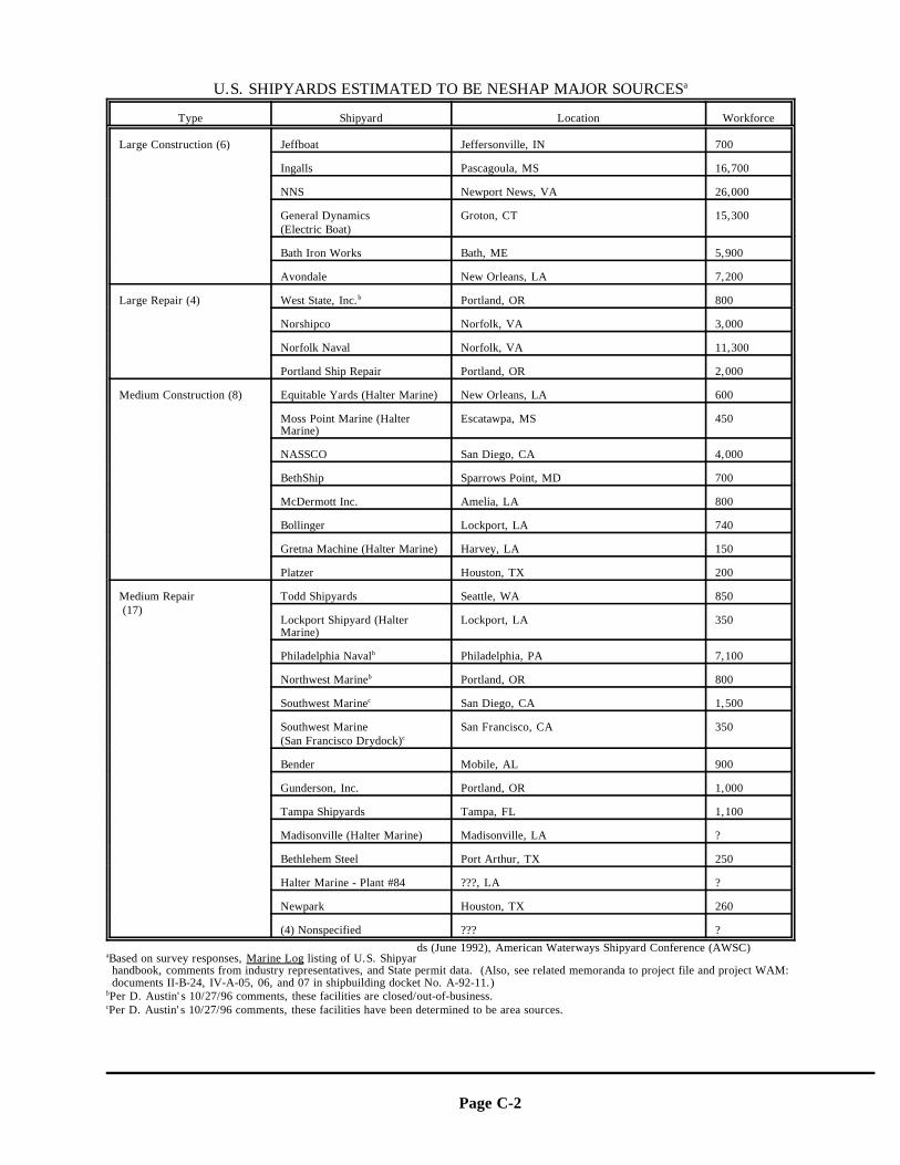
Page C-2
U.S. SHIPYARDS ESTIMATED TO BE NESHAP MAJOR SOURCESa
Type Shipyard Location Workforce
Large Construction (6) Jeffboat Jeffersonville, IN 700
Ingalls Pascagoula, MS 16,700
NNS Newport News, VA 26,000
General Dynamics Groton, CT 15,300(Electric Boat)
Bath Iron Works Bath, ME 5,900
Avondale New Orleans, LA 7,200
Large Repair (4) West State, Inc. Portland, OR 800b
Norshipco Norfolk, VA 3,000
Norfolk Naval Norfolk, VA 11,300
Portland Ship Repair Portland, OR 2,000
Medium Construction (8) Equitable Yards (Halter Marine) New Orleans, LA 600 Moss Point Marine (Halter Escatawpa, MS 450
Marine)
NASSCO San Diego, CA 4,000
BethShip Sparrows Point, MD 700
McDermott Inc. Amelia, LA 800
Bollinger Lockport, LA 740
Gretna Machine (Halter Marine) Harvey, LA 150
Platzer Houston, TX 200
Medium Repair Todd Shipyards Seattle, WA 850 (17)
Lockport Shipyard (Halter Lockport, LA 350Marine)
Philadelphia Naval Philadelphia, PA 7,100b
Northwest Marine Portland, OR 800b
Southwest Marine San Diego, CA 1,500c
Southwest Marine San Francisco, CA 350(San Francisco Drydock)c
Bender Mobile, AL 900
Gunderson, Inc. Portland, OR 1,000
Tampa Shipyards Tampa, FL 1,100
Madisonville (Halter Marine) Madisonville, LA ?
Bethlehem Steel Port Arthur, TX 250
Halter Marine - Plant #84 ???, LA ?
Newpark Houston, TX 260
(4) Nonspecified ??? ?
ds (June 1992), American Waterways Shipyard Conference (AWSC)Based on survey responses, Marine Log listing of U.S. Shipyara
handbook, comments from industry representatives, and State permit data. (Also, see related memoranda to project file and project WAM:documents II-B-24, IV-A-05, 06, and 07 in shipbuilding docket No. A-92-11.)Per D. Austin's 10/27/96 comments, these facilities are closed/out-of-business.b
Per D. Austin's 10/27/96 comments, these facilities have been determined to be area sources.c

Page D-1
APPENDIX D
EXAMPLE INITIAL NOTIFICATION
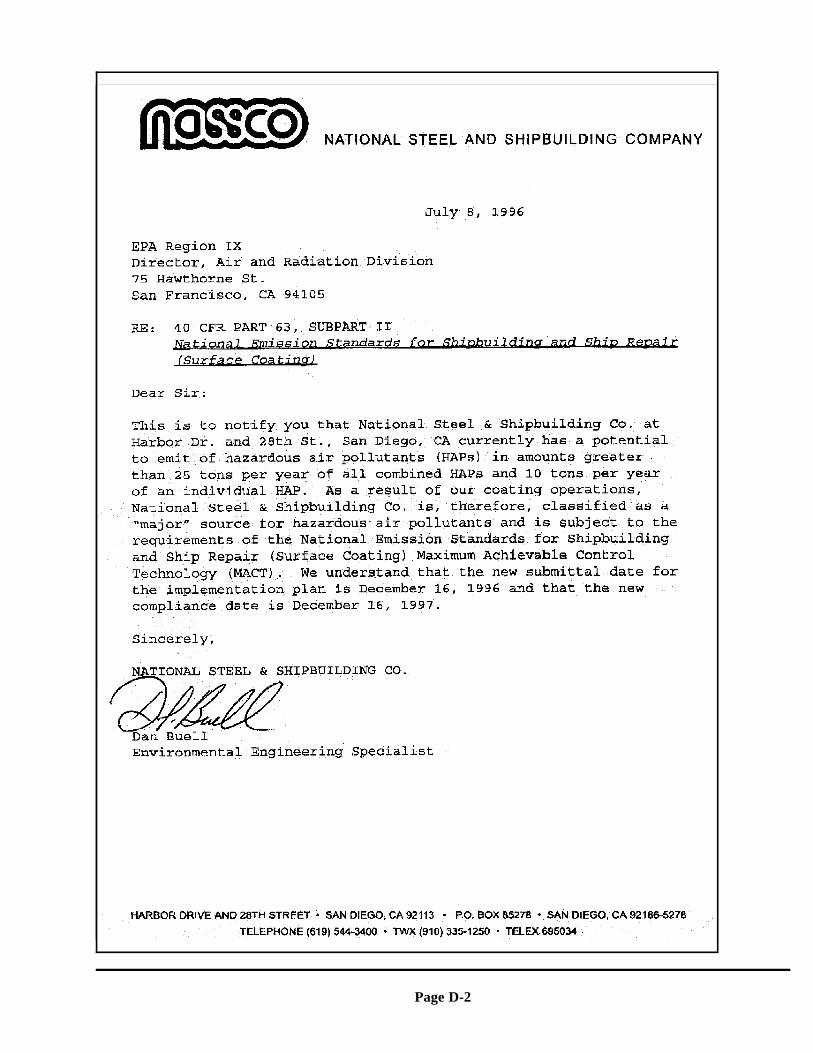
Page D-2

Page D-3
Page E-1
APPENDIX E
EXAMPLE IMPLEMENTATION PLAN
The following "Shipyard MACT Implementation Plan" was prepared by Mr. Dana Austin ofAustin Environmental, Inc. for NSRP, Task N1-92-2, Subtask 12.
Page E-2
AOK SHIPYARDSThe Best in the West
SHIPYARD MACTIMPLEMENTATION PLAN
April 1996
Prepared for:John Smith
US EPA Region XXX
Page E-3
123 Elm StreetAnytown, USA 98765-1234
AOK Shipyards Coating Compliance Plan April, 1996
Page E-4
Table of Contents
1. COATING COMPLIANCE PROCEDURES . . . . . . . . . . . . . . . . . . . . . . . . . . 1
1.0 COATING IDENTIFICATION AND CERTIFICATION . . . . . . . . . . . . . 2
1.0.1 Coating Identification . . . . . . . . . . . . . . . . . . . . . . . . . . . . . . . 2
1.0.2 VOC or VOHAP Content Above Limit . . . . . . . . . . . . . . . . . . . . 2
1.0.3 Unknown VOC Content . . . . . . . . . . . . . . . . . . . . . . . . . . . . . . 3
1.0.4 Container Inspection . . . . . . . . . . . . . . . . . . . . . . . . . . . . . . . . 3
1.1 OPTION 1 and OPTION 4 . . . . . . . . . . . . . . . . . . . . . . . . . . . . . . . . 4
1.1.1 Certification . . . . . . . . . . . . . . . . . . . . . . . . . . . . . . . . . . . . . 4
1.1.2 Notification . . . . . . . . . . . . . . . . . . . . . . . . . . . . . . . . . . . . . 4
1.2 OPTION 2, OPTION 3 and OPTION 4 . . . . . . . . . . . . . . . . . . . . . . . . 4
1.2.1 Calculation of Thinning Ratios . . . . . . . . . . . . . . . . . . . . . . . . . 4
1.2.2 Notification . . . . . . . . . . . . . . . . . . . . . . . . . . . . . . . . . . . . . 7
1.2.3 Paint Crew Daily Records . . . . . . . . . . . . . . . . . . . . . . . . . . . . 7
1.2.4 Thinner Group Designation "By Use" . . . . . . . . . . . . . . . . . . . . . 7
1.2.5 Determination of Compliance . . . . . . . . . . . . . . . . . . . . . . . . . . 8
2. RECORD KEEPING PROCEDURES . . . . . . . . . . . . . . . . . . . . . . . . . . . . . . 8
3. TRANSFER, HANDLING, AND STORAGE PROCEDURES . . . . . . . . . . . . . . 9
3.0 Work Practices . . . . . . . . . . . . . . . . . . . . . . . . . . . . . . . . . . . . . . . . 9
3.1 Self-Inspection . . . . . . . . . . . . . . . . . . . . . . . . . . . . . . . . . . . . . . . 10
APPENDIX A: FORMS . . . . . . . . . . . . . . . . . . . . . . . . . . . . . . . . . . . . . . . . . . 12
PAINT CREW USAGE FORM . . . . . . . . . . . . . . . . . . . . . . . . . . . . . . . . . 14
CONTAINER COMPLIANCE FORM . . . . . . . . . . . . . . . . . . . . . . . . . . . . 15
METHOD 24 TEST RESULTS FORM . . . . . . . . . . . . . . . . . . . . . . . . . . . . 16
AOK Shipyards Coating Compliance Plan April, 1996
Page E-5
PAINT AND THINNER USAGE LOG . . . . . . . . . . . . . . . . . . . . . . . . . . . . 17
NO THINNING LABEL . . . . . . . . . . . . . . . . . . . . . . . . . . . . . . . . . . . . . 18
MAXIMUM ALLOWABLE THINNING LABEL . . . . . . . . . . . . . . . . . . . . . 19
CALCULATION SHEET (SIDE 1) FOR OPTIONS 2 AND 3 . . . . . . . . . . . . . 20
CALCULATION SHEET (SIDE 2) . . . . . . . . . . . . . . . . . . . . . . . . . . . . . . 22
APPENDIX B: MARINE COATING DATA SHEETS . . . . . . . . . . . . . . . . . . . . . . . 23
VOC DATA SHEET . . . . . . . . . . . . . . . . . . . . . . . . . . . . . . . . . . . . . . . . 24
VOLATILE ORGANIC HAP (VOHAP) LIMITS FOR MARINE COATINGS . . 26
SHIPYARD MACT MARINE COATING EXPRESSIONS AND EQUATIONS . . 27
40 CFR 51.100 (s) - EXEMPT COMPOUNDS . . . . . . . . . . . . . . . . . . . . . . . 28
APPENDIX C: COATING DEFINITIONS . . . . . . . . . . . . . . . . . . . . . . . . . . . . . . 29
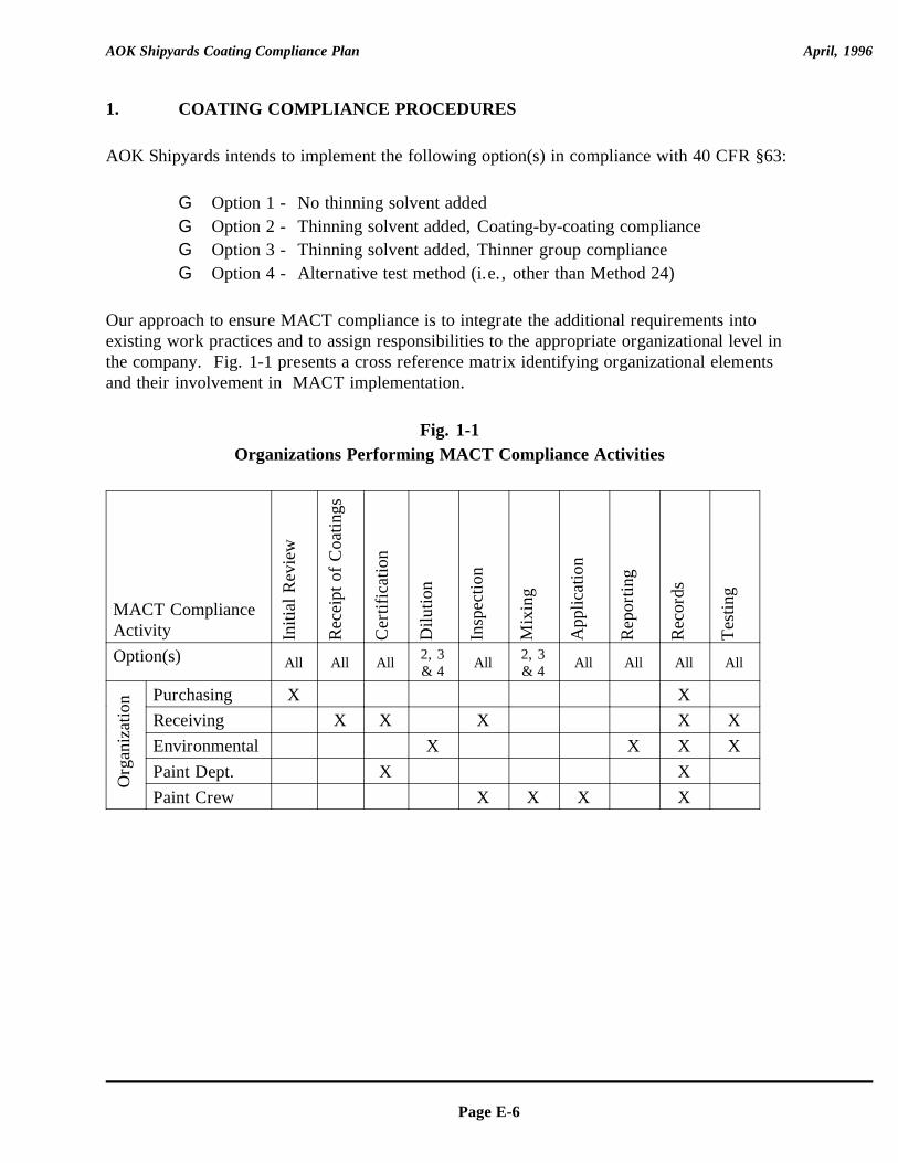
AOK Shipyards Coating Compliance Plan April, 1996
Page E-6
1. COATING COMPLIANCE PROCEDURES
AOK Shipyards intends to implement the following option(s) in compliance with 40 CFR §63:
G Option 1 - No thinning solvent addedG Option 2 - Thinning solvent added, Coating-by-coating complianceG Option 3 - Thinning solvent added, Thinner group complianceG Option 4 - Alternative test method (i.e., other than Method 24)
Our approach to ensure MACT compliance is to integrate the additional requirements intoexisting work practices and to assign responsibilities to the appropriate organizational level inthe company. Fig. 1-1 presents a cross reference matrix identifying organizational elementsand their involvement in MACT implementation.
Fig. 1-1Organizations Performing MACT Compliance Activities
MACT ComplianceActivity In
itial
Rev
iew
Rec
eipt
of
Coa
tings
Cer
tific
atio
n
Dilu
tion
Insp
ectio
n
Mix
ing
App
licat
ion
Rep
ortin
g
Rec
ords
Tes
ting
Option(s) All All All All All All All All2, 3 2, 3& 4 & 4
Org
aniz
atio
n Purchasing X XReceiving X X X X XEnvironmental X X X XPaint Dept. X XPaint Crew X X X X
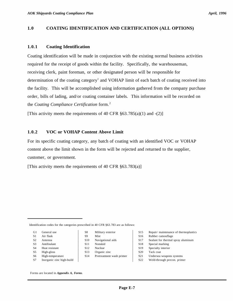
AOK Shipyards Coating Compliance Plan April, 1996
Identification codes for the categories prescribed in 40 CFR §63.783 are as follows:
G1 General use S8 Military exterior S15 Repair/ maintenance of thermoplasticsS1 Air flask S9 Mist S16 Rubber camouflageS2 Antenna S10 Navigational aids S17 Sealant for thermal spray aluminumS3 Antifoulant S11 Nonskid S18 Special marking S4 Heat resistant S12 Nuclear S19 Specialty interiorS5 High-gloss S13 Organic zinc S20 Tack coatS6 High-temperature S14 Pretreatment wash primer S21 Undersea weapons systemsS7 Inorganic zinc high-build S22 Weld-through precon. primer
Forms are located in Appendix A, Forms.
Page E-7
1.0 COATING IDENTIFICATION AND CERTIFICATION (ALL OPTIONS)
1.0.1 Coating Identification
Coating identification will be made in conjunction with the existing normal business activities
required for the receipt of goods within the facility. Specifically, the warehouseman,
receiving clerk, paint foreman, or other designated person will be responsible for
determination of the coating category and VOHAP limit of each batch of coating received into1
the facility. This will be accomplished using information gathered from the company purchase
order, bills of lading, and/or coating container labels. This information will be recorded on
the Coating Compliance Certification form. 2
[This activity meets the requirements of 40 CFR §63.785(a)(1) and -(2)]
1.0.2 VOC or VOHAP Content Above Limit
For its specific coating category, any batch of coating with an identified VOC or VOHAP
content above the limit shown in the form will be rejected and returned to the supplier,
customer, or government.
[This activity meets the requirements of 40 CFR §63.783(a)]
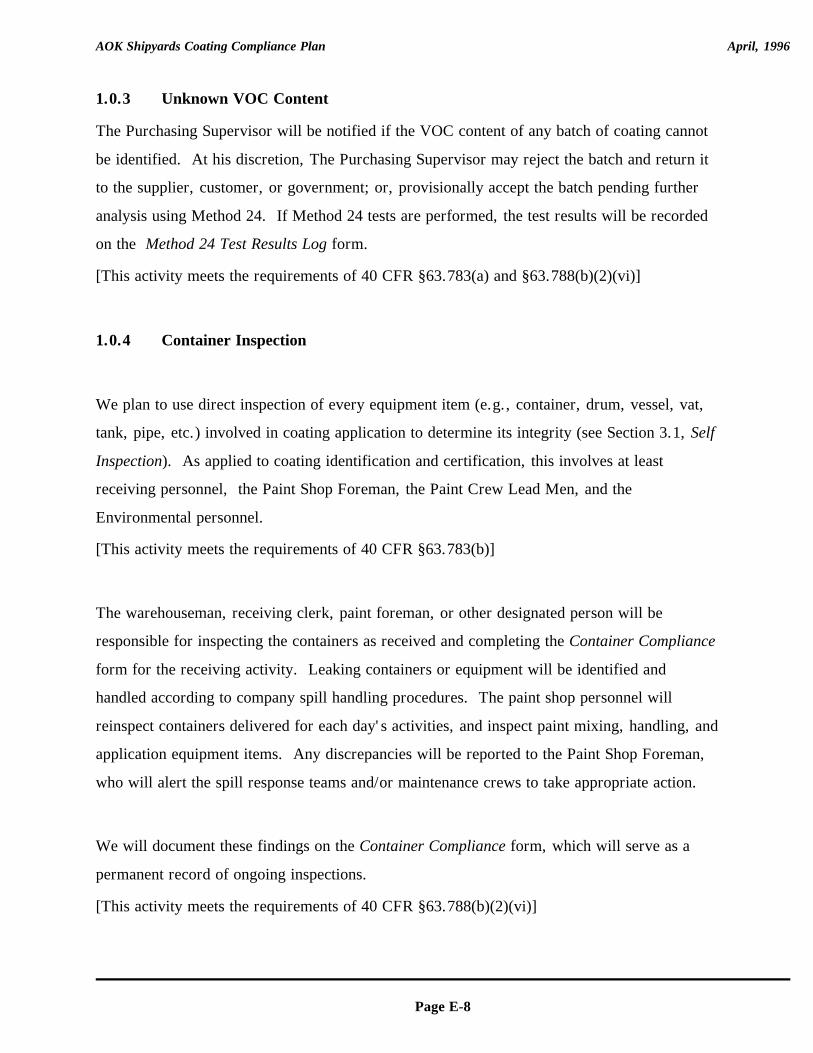
AOK Shipyards Coating Compliance Plan April, 1996
Page E-8
1.0.3 Unknown VOC Content
The Purchasing Supervisor will be notified if the VOC content of any batch of coating cannot
be identified. At his discretion, The Purchasing Supervisor may reject the batch and return it
to the supplier, customer, or government; or, provisionally accept the batch pending further
analysis using Method 24. If Method 24 tests are performed, the test results will be recorded
on the Method 24 Test Results Log form.
[This activity meets the requirements of 40 CFR §63.783(a) and §63.788(b)(2)(vi)]
1.0.4 Container Inspection
We plan to use direct inspection of every equipment item (e.g., container, drum, vessel, vat,
tank, pipe, etc.) involved in coating application to determine its integrity (see Section 3.1, Self
Inspection). As applied to coating identification and certification, this involves at least
receiving personnel, the Paint Shop Foreman, the Paint Crew Lead Men, and the
Environmental personnel.
[This activity meets the requirements of 40 CFR §63.783(b)]
The warehouseman, receiving clerk, paint foreman, or other designated person will be
responsible for inspecting the containers as received and completing the Container Compliance
form for the receiving activity. Leaking containers or equipment will be identified and
handled according to company spill handling procedures. The paint shop personnel will
reinspect containers delivered for each day's activities, and inspect paint mixing, handling, and
application equipment items. Any discrepancies will be reported to the Paint Shop Foreman,
who will alert the spill response teams and/or maintenance crews to take appropriate action.
We will document these findings on the Container Compliance form, which will serve as a
permanent record of ongoing inspections.
[This activity meets the requirements of 40 CFR §63.788(b)(2)(vi)]
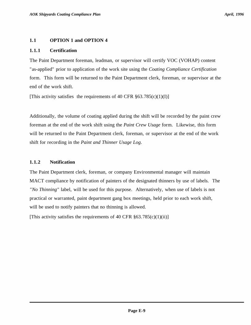
AOK Shipyards Coating Compliance Plan April, 1996
Page E-9
1.1 OPTION 1 and OPTION 4
1.1.1 Certification
The Paint Department foreman, leadman, or supervisor will certify VOC (VOHAP) content
"as-applied" prior to application of the work site using the Coating Compliance Certification
form. This form will be returned to the Paint Department clerk, foreman, or supervisor at the
end of the work shift.
[This activity satisfies the requirements of 40 CFR §63.785(c)(1)(I)]
Additionally, the volume of coating applied during the shift will be recorded by the paint crew
foreman at the end of the work shift using the Paint Crew Usage form. Likewise, this form
will be returned to the Paint Department clerk, foreman, or supervisor at the end of the work
shift for recording in the Paint and Thinner Usage Log.
1.1.2 Notification
The Paint Department clerk, foreman, or company Environmental manager will maintain
MACT compliance by notification of painters of the designated thinners by use of labels. The
"No Thinning" label, will be used for this purpose. Alternatively, when use of labels is not
practical or warranted, paint department gang box meetings, held prior to each work shift,
will be used to notify painters that no thinning is allowed.
[This activity satisfies the requirements of 40 CFR §63.785(c)(1)(ii)]
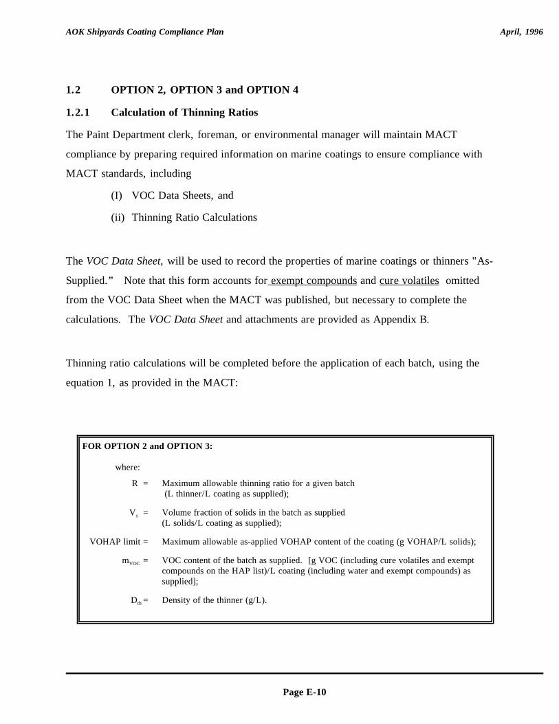
AOK Shipyards Coating Compliance Plan April, 1996
Page E-10
FOR OPTION 2 and OPTION 3:
where:
R = Maximum allowable thinning ratio for a given batch (L thinner/L coating as supplied);
V =s Volume fraction of solids in the batch as supplied (L solids/L coating as supplied);
VOHAP limit = Maximum allowable as-applied VOHAP content of the coating (g VOHAP/L solids);
m =VOC VOC content of the batch as supplied. [g VOC (including cure volatiles and exemptcompounds on the HAP list)/L coating (including water and exempt compounds) assupplied];
D =th Density of the thinner (g/L).
1.2 OPTION 2, OPTION 3 and OPTION 4
1.2.1 Calculation of Thinning Ratios
The Paint Department clerk, foreman, or environmental manager will maintain MACT
compliance by preparing required information on marine coatings to ensure compliance with
MACT standards, including
(I) VOC Data Sheets, and
(ii) Thinning Ratio Calculations
The VOC Data Sheet, will be used to record the properties of marine coatings or thinners "As-
Supplied.” Note that this form accounts for exempt compounds and cure volatiles omitted
from the VOC Data Sheet when the MACT was published, but necessary to complete the
calculations. The VOC Data Sheet and attachments are provided as Appendix B.
Thinning ratio calculations will be completed before the application of each batch, using the
equation 1, as provided in the MACT:
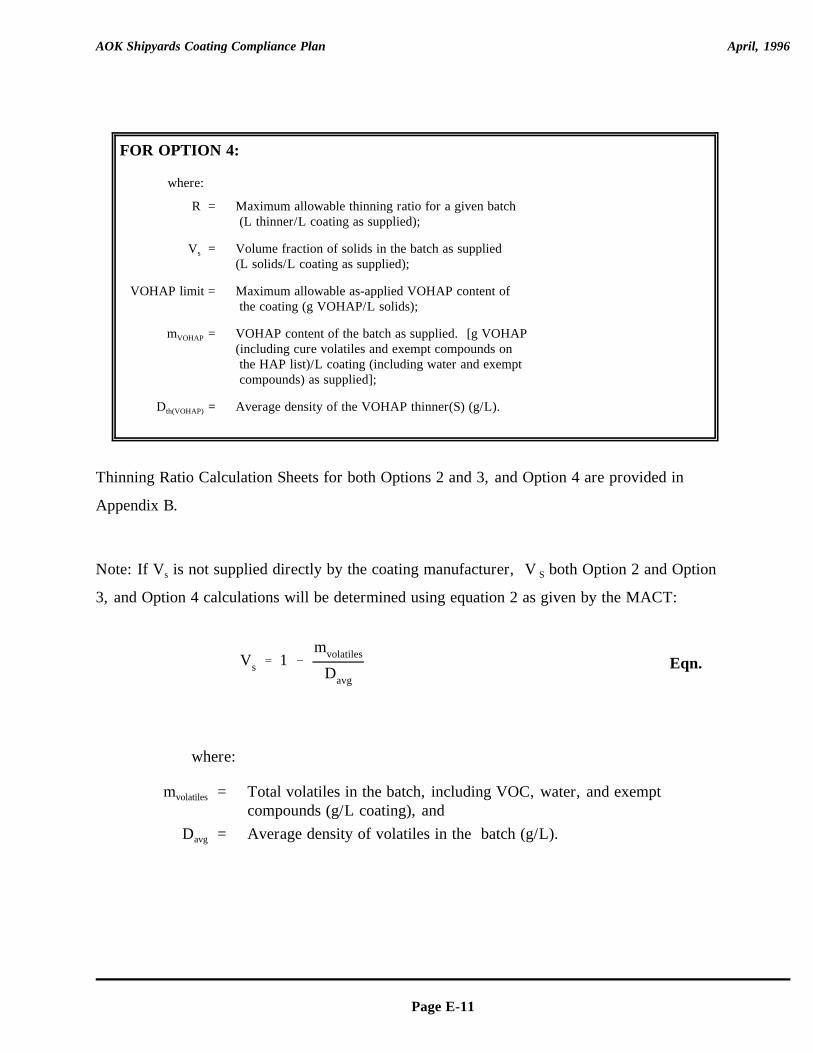
Vs ' 1 &mvolatiles
Davg
AOK Shipyards Coating Compliance Plan April, 1996
Page E-11
FOR OPTION 4:
where:
R = Maximum allowable thinning ratio for a given batch (L thinner/L coating as supplied);
V =s Volume fraction of solids in the batch as supplied (L solids/L coating as supplied);
VOHAP limit = Maximum allowable as-applied VOHAP content of the coating (g VOHAP/L solids);
m =VOHAP VOHAP content of the batch as supplied. [g VOHAP (including cure volatiles and exempt compounds on the HAP list)/L coating (including water and exempt compounds) as supplied];
D =th(VOHAP) Average density of the VOHAP thinner(S) (g/L).
Eqn.
Thinning Ratio Calculation Sheets for both Options 2 and 3, and Option 4 are provided in
Appendix B.
Note: If V is not supplied directly by the coating manufacturer, V both Option 2 and Options S
3, and Option 4 calculations will be determined using equation 2 as given by the MACT:
where:
m = Total volatiles in the batch, including VOC, water, and exemptvolatiles
compounds (g/L coating), andD = Average density of volatiles in the batch (g/L).avg
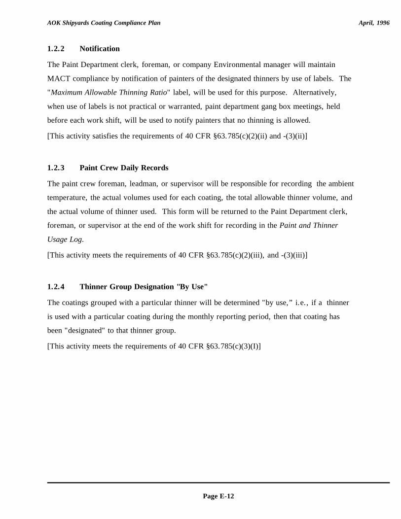
AOK Shipyards Coating Compliance Plan April, 1996
Page E-12
1.2.2 Notification
The Paint Department clerk, foreman, or company Environmental manager will maintain
MACT compliance by notification of painters of the designated thinners by use of labels. The
"Maximum Allowable Thinning Ratio" label, will be used for this purpose. Alternatively,
when use of labels is not practical or warranted, paint department gang box meetings, held
before each work shift, will be used to notify painters that no thinning is allowed.
[This activity satisfies the requirements of 40 CFR §63.785(c)(2)(ii) and -(3)(ii)]
1.2.3 Paint Crew Daily Records
The paint crew foreman, leadman, or supervisor will be responsible for recording the ambient
temperature, the actual volumes used for each coating, the total allowable thinner volume, and
the actual volume of thinner used. This form will be returned to the Paint Department clerk,
foreman, or supervisor at the end of the work shift for recording in the Paint and Thinner
Usage Log.
[This activity meets the requirements of 40 CFR §63.785(c)(2)(iii), and -(3)(iii)]
1.2.4 Thinner Group Designation "By Use"
The coatings grouped with a particular thinner will be determined "by use,” i.e., if a thinner
is used with a particular coating during the monthly reporting period, then that coating has
been "designated" to that thinner group.
[This activity meets the requirements of 40 CFR §63.785(c)(3)(I)]
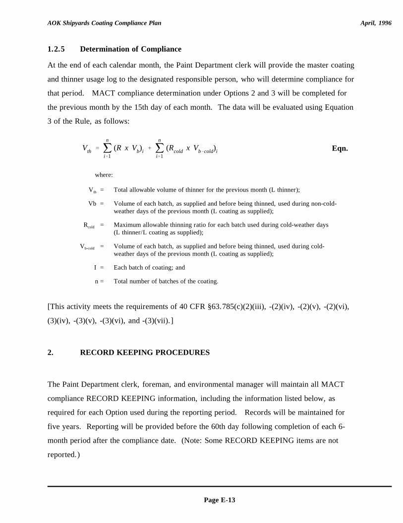
Vth ' jn
i'1(R x Vb)i % j
n
i'1(Rcold x Vb&cold)i
AOK Shipyards Coating Compliance Plan April, 1996
Page E-13
Eqn.
1.2.5 Determination of Compliance
At the end of each calendar month, the Paint Department clerk will provide the master coating
and thinner usage log to the designated responsible person, who will determine compliance for
that period. MACT compliance determination under Options 2 and 3 will be completed for
the previous month by the 15th day of each month. The data will be evaluated using Equation
3 of the Rule, as follows:
where:
V = Total allowable volume of thinner for the previous month (L thinner);th
Vb = Volume of each batch, as supplied and before being thinned, used during non-cold-weather days of the previous month (L coating as supplied);
R = Maximum allowable thinning ratio for each batch used during cold-weather dayscold
(L thinner/L coating as supplied);
V = Volume of each batch, as supplied and before being thinned, used during cold-b-cold
weather days of the previous month (L coating as supplied);
I = Each batch of coating; and
n = Total number of batches of the coating.
[This activity meets the requirements of 40 CFR §63.785(c)(2)(iii), -(2)(iv), -(2)(v), -(2)(vi),
(3)(iv), -(3)(v), -(3)(vi), and -(3)(vii).]
2. RECORD KEEPING PROCEDURES
The Paint Department clerk, foreman, and environmental manager will maintain all MACT
compliance RECORD KEEPING information, including the information listed below, as
required for each Option used during the reporting period. Records will be maintained for
five years. Reporting will be provided before the 60th day following completion of each 6-
month period after the compliance date. (Note: Some RECORD KEEPING items are not
reported.)
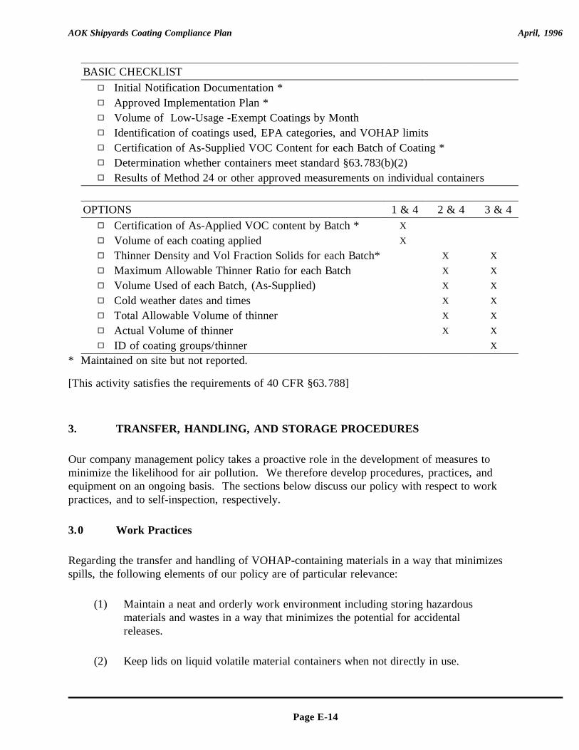
AOK Shipyards Coating Compliance Plan April, 1996
Page E-14
BASIC CHECKLIST9 Initial Notification Documentation *9 Approved Implementation Plan *9 Volume of Low-Usage -Exempt Coatings by Month9 Identification of coatings used, EPA categories, and VOHAP limits9 Certification of As-Supplied VOC Content for each Batch of Coating *9 Determination whether containers meet standard §63.783(b)(2)9 Results of Method 24 or other approved measurements on individual containers
OPTIONS 1 & 4 2 & 4 3 & 49 Certification of As-Applied VOC content by Batch * X
9 Volume of each coating applied X
9 Thinner Density and Vol Fraction Solids for each Batch* X X
9 Maximum Allowable Thinner Ratio for each Batch X X
9 Volume Used of each Batch, (As-Supplied) X X
9 Cold weather dates and times X X
9 Total Allowable Volume of thinner X X
9 Actual Volume of thinner X X
9 ID of coating groups/thinner X
* Maintained on site but not reported.
[This activity satisfies the requirements of 40 CFR §63.788]
3. TRANSFER, HANDLING, AND STORAGE PROCEDURES
Our company management policy takes a proactive role in the development of measures tominimize the likelihood for air pollution. We therefore develop procedures, practices, andequipment on an ongoing basis. The sections below discuss our policy with respect to workpractices, and to self-inspection, respectively.
3.0 Work Practices
Regarding the transfer and handling of VOHAP-containing materials in a way that minimizesspills, the following elements of our policy are of particular relevance:
(1) Maintain a neat and orderly work environment including storing hazardousmaterials and wastes in a way that minimizes the potential for accidentalreleases.
(2) Keep lids on liquid volatile material containers when not directly in use.
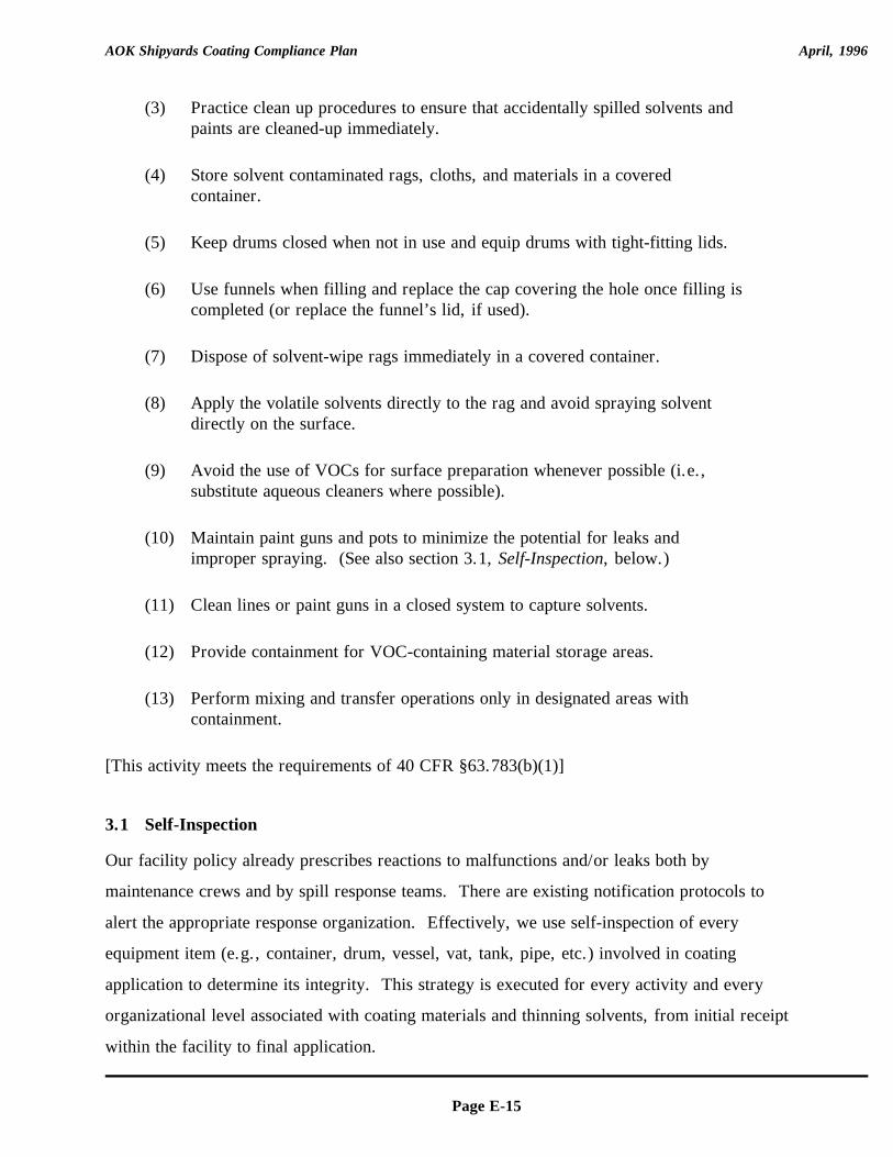
AOK Shipyards Coating Compliance Plan April, 1996
Page E-15
(3) Practice clean up procedures to ensure that accidentally spilled solvents andpaints are cleaned-up immediately.
(4) Store solvent contaminated rags, cloths, and materials in a coveredcontainer.
(5) Keep drums closed when not in use and equip drums with tight-fitting lids.
(6) Use funnels when filling and replace the cap covering the hole once filling iscompleted (or replace the funnel’s lid, if used).
(7) Dispose of solvent-wipe rags immediately in a covered container.
(8) Apply the volatile solvents directly to the rag and avoid spraying solventdirectly on the surface.
(9) Avoid the use of VOCs for surface preparation whenever possible (i.e.,substitute aqueous cleaners where possible).
(10) Maintain paint guns and pots to minimize the potential for leaks andimproper spraying. (See also section 3.1, Self-Inspection, below.)
(11) Clean lines or paint guns in a closed system to capture solvents.
(12) Provide containment for VOC-containing material storage areas.
(13) Perform mixing and transfer operations only in designated areas withcontainment.
[This activity meets the requirements of 40 CFR §63.783(b)(1)]
3.1 Self-Inspection
Our facility policy already prescribes reactions to malfunctions and/or leaks both by
maintenance crews and by spill response teams. There are existing notification protocols to
alert the appropriate response organization. Effectively, we use self-inspection of every
equipment item (e.g., container, drum, vessel, vat, tank, pipe, etc.) involved in coating
application to determine its integrity. This strategy is executed for every activity and every
organizational level associated with coating materials and thinning solvents, from initial receipt
within the facility to final application.
AOK Shipyards Coating Compliance Plan April, 1996
Page E-16
[These policies and procedures meet the requirements of 40 CFR §63.783(b)(2).]
For compliance with MACT RECORD KEEPING requirements, we plan to document
container self-inspection findings on the Container Compliance Form. This form will serve as
a permanent record, and will be maintained for a minimum of 5 years.
[This activity assures compliance with 40 CFR §63.788(b)(2)(vi).]
Page E-17
Attachment A: FORMS
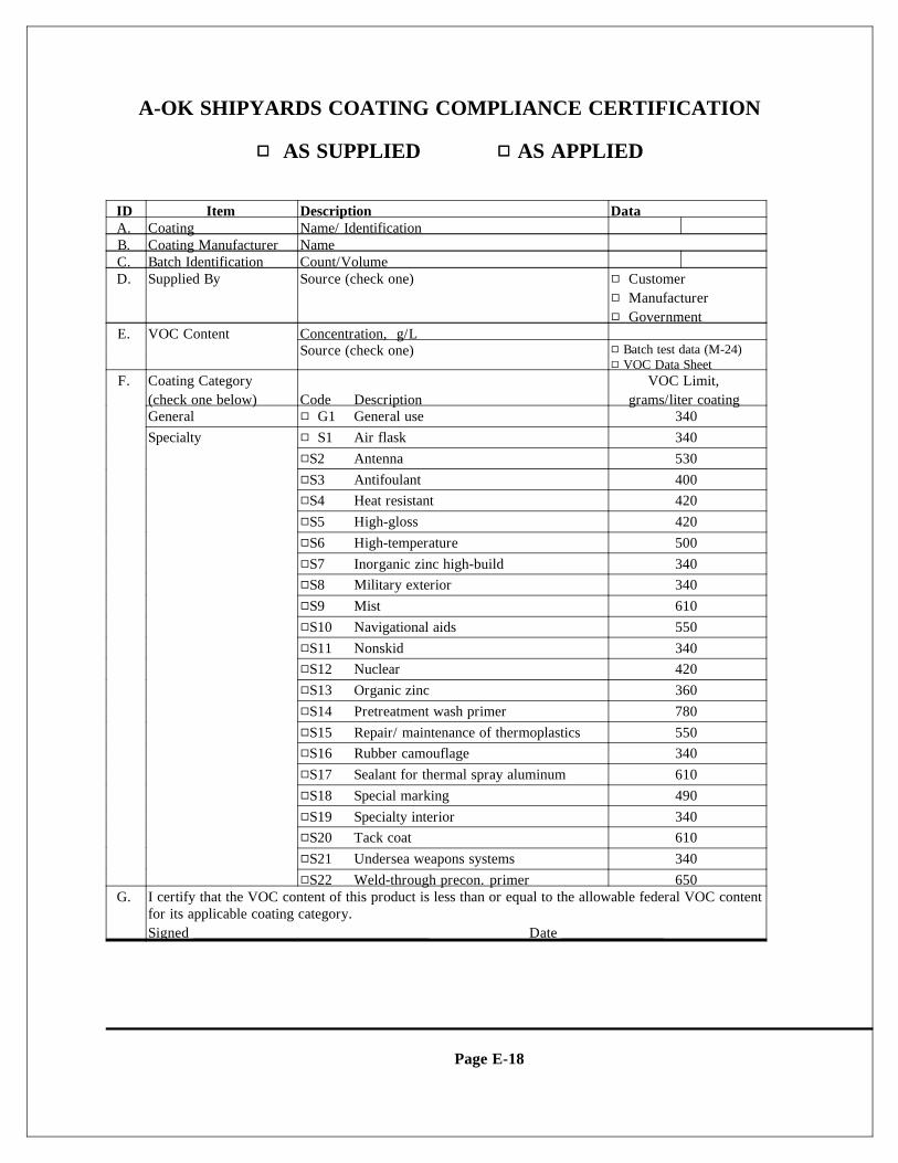
Page E-18
A-OK SHIPYARDS COATING COMPLIANCE CERTIFICATION
99 AS SUPPLIED 99 AS APPLIED
ID Item Description DataA. Coating Name/ IdentificationB. Coating Manufacturer NameC. Batch Identification Count/VolumeD. Supplied By Source (check one) 9 Customer
9 Manufacturer9 Government
E. VOC Content Concentration, g/LSource (check one) 9 Batch test data (M-24)
9 VOC Data SheetF. Coating Category VOC Limit,
(check one below) Code Description grams/liter coating General 9 G1 General use 340Specialty 9 S1 Air flask 340
9S2 Antenna 5309S3 Antifoulant 4009S4 Heat resistant 4209S5 High-gloss 4209S6 High-temperature 5009S7 Inorganic zinc high-build 3409S8 Military exterior 3409S9 Mist 6109S10 Navigational aids 5509S11 Nonskid 3409S12 Nuclear 4209S13 Organic zinc 3609S14 Pretreatment wash primer 7809S15 Repair/ maintenance of thermoplastics 5509S16 Rubber camouflage 3409S17 Sealant for thermal spray aluminum 6109S18 Special marking 4909S19 Specialty interior 3409S20 Tack coat 6109S21 Undersea weapons systems 3409S22 Weld-through precon. primer 650
G. I certify that the VOC content of this product is less than or equal to the allowable federal VOC contentfor its applicable coating category.Signed ________________________________ Date ______________
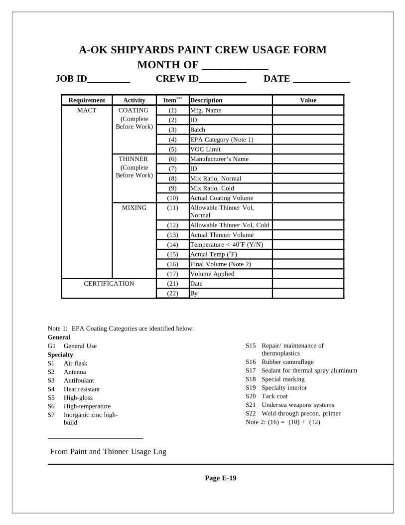
From Paint and Thinner Usage Log
Page E-19
A-OK SHIPYARDS PAINT CREW USAGE FORMMONTH OF ____________
JOB ID_________ CREW ID__________ DATE ____________
Requirement Activity Item Description Value***
MACT COATING (1) Mfg. Name(Complete
Before Work)(2) ID
(3) Batch
(4) EPA Category (Note 1)
(5) VOC Limit
THINNER (6) Manufacturer’s Name(Complete
Before Work)(7) ID
(8) Mix Ratio, Normal
(9) Mix Ratio, Cold
(10) Actual Coating Volume
MIXING (11) Allowable Thinner Vol,Normal
(12) Allowable Thinner Vol, Cold
(13) Actual Thinner Volume
(14) Temperature <40<F (Y/N)
(15) Actual Temp (<F)
(16) Final Volume (Note 2)
(17) Volume Applied
CERTIFICATION (21) Date
(22) By
Note 1: EPA Coating Categories are identified below:GeneralG1 General UseSpecialtyS1 Air flask S2 AntennaS3 AntifoulantS4 Heat resistantS5 High-glossS6 High-temperatureS7 Inorganic zinc high-
build
S15 Repair/ maintenance ofthermoplastics
S16 Rubber camouflageS17 Sealant for thermal spray aluminumS18 Special marking S19 Specialty interiorS20 Tack coatS21 Undersea weapons systemsS22 Weld-through precon. primerNote 2: (16) = (10) + (12)

Page E-20
S8 Military exteriorS9 MistS10 Navigational aidsS11 NonskidS12 NuclearS13 Organic zincS14 Pretreatment wash
primer
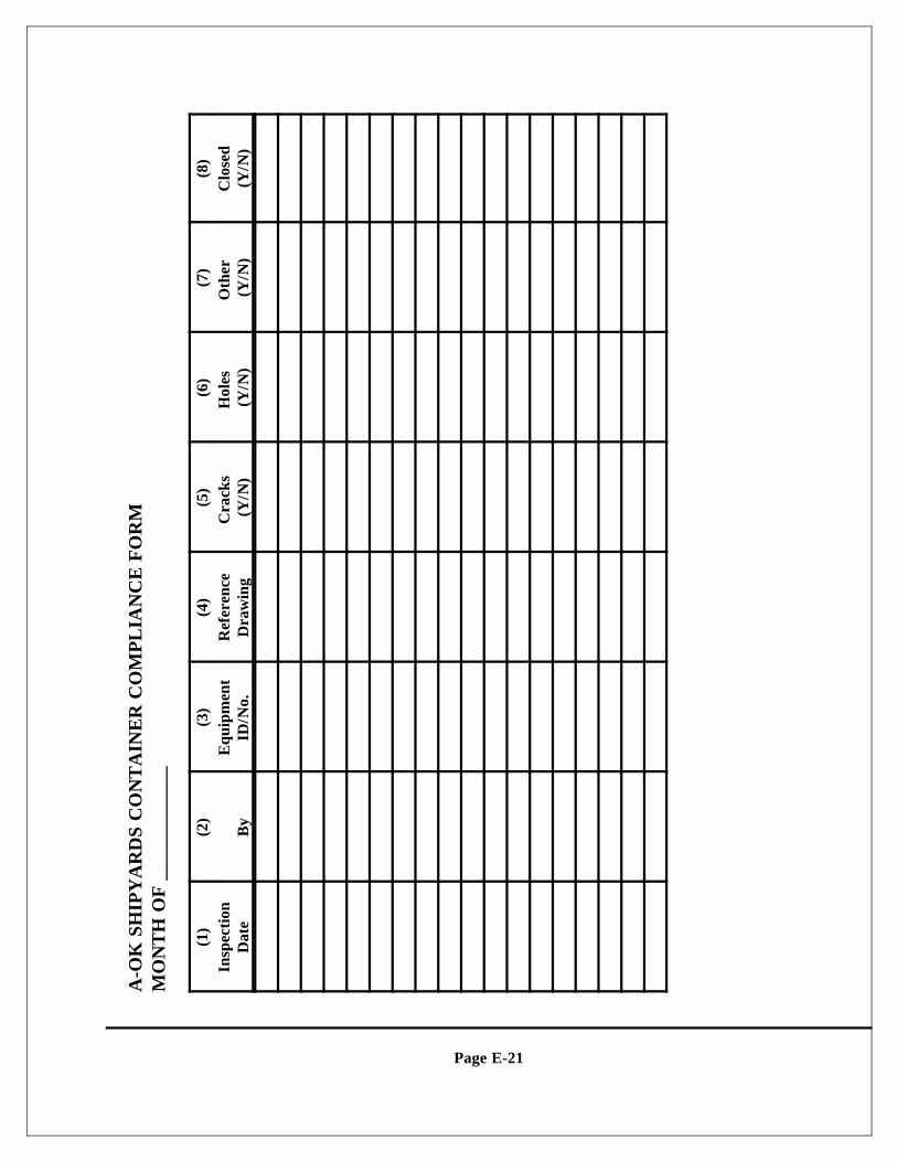
Page E-21
A-O
K S
HIP
YA
RD
S C
ON
TA
INE
R C
OM
PL
IAN
CE
FO
RM
MO
NT
H O
F _
____
____
___
(1)
(2)
(3)
(4)
(5)
(6)
(7)
(8)
Insp
ecti
onD
ate
By
Equ
ipm
ent
ID/N
o.R
efer
ence
Dra
win
gC
rack
s (Y
/N)
Hol
es
(Y/N
)O
ther
(Y
/N)
Clo
sed
(Y/N
)
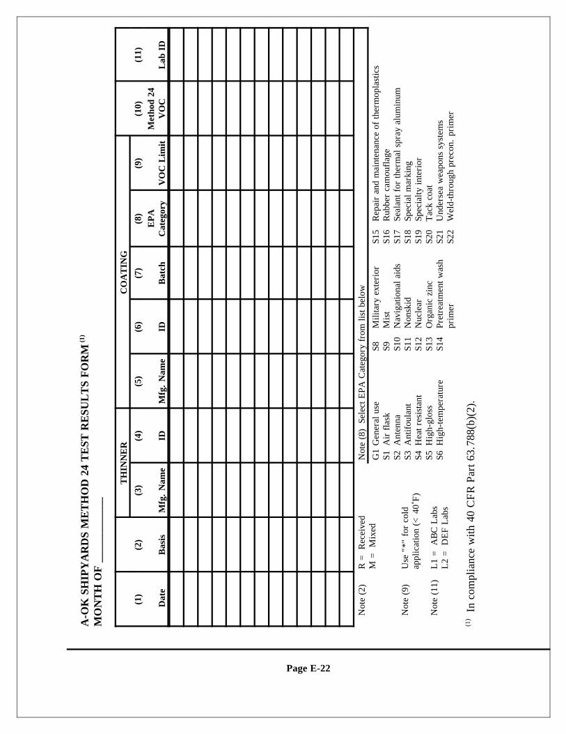
Page E-22
A-O
K S
HIP
YA
RD
S M
ET
HO
D 2
4 T
EST
RE
SUL
TS
FO
RM
(1)
MO
NT
H O
F _
____
____
___
TH
INN
ER
CO
AT
ING
(1)
(2)
(3)
(4)
(5)
(6)
(7)
(8)
(9)
(10)
(11)
Dat
eB
asis
Mfg
. N
ame
IDM
fg.
Nam
eID
Bat
chE
PA
Cat
egor
yV
OC
Lim
itM
etho
d 24
VO
CL
ab I
D
N
ote
(2)
R =
Rec
eive
dM
= M
ixed
Not
e (8
) S
elec
t EPA
Cat
egor
y fr
om li
st b
elow
G1
Gen
eral
use
S1A
ir f
lask
S2
Ant
enna
S3A
ntif
oula
ntS4
Hea
t res
ista
ntS5
Hig
h-gl
oss
S6H
igh-
tem
pera
ture
S8M
ilita
ry e
xter
ior
S9M
ist
S10
Nav
igat
iona
l aid
sS1
1N
onsk
idS1
2N
ucle
arS1
3O
rgan
ic z
inc
S14
Pret
reat
men
t was
hpr
imer
S15
Rep
air
and
mai
nten
ance
of
ther
mop
last
ics
S16
Rub
ber
cam
oufl
age
S17
Seal
ant f
or th
erm
al s
pray
alu
min
umS1
8Sp
ecia
l mar
king
S1
9Sp
ecia
lty in
teri
orS2
0T
ack
coat
S21
Und
erse
a w
eapo
ns s
yste
ms
S22
Wel
d-th
roug
h pr
econ
. pr
imer
N
ote
(9)
Use
"*"
for
col
dap
plic
atio
n (<
40<F
)
N
ote
(11)
L1
= A
BC
Lab
sL
2 =
DE
F L
abs
In
com
plia
nce
with
40
CF
R P
art 6
3.78
8(b)
(2).
(1)
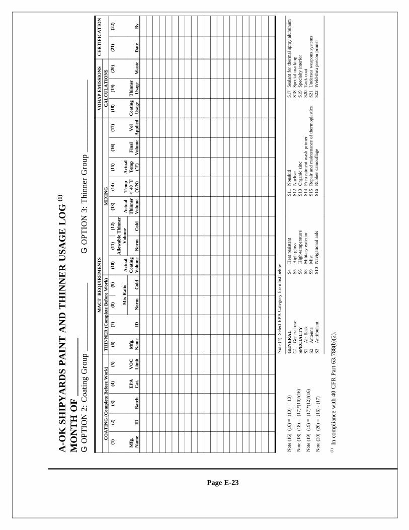
Page E-23
A-O
K S
HIP
YA
RD
S P
AIN
T A
ND
TH
INN
ER
USA
GE
LO
G (1
)
MO
NT
H O
F _
____
____
___
G O
PTIO
N 2
: C
oatin
g G
roup
___
____
____
____
__
G
OPT
ION
3:
Thi
nner
Gro
up _
____
____
____
____
_
MA
CT
RE
QU
IRE
ME
NT
SV
OH
AP
EM
ISSI
ON
SC
ER
TIF
ICA
TIO
NC
OA
TIN
G (
Com
plet
e B
efor
e W
ork)
TH
INN
ER
(C
ompl
ete
Bef
ore
Wor
k)M
IXIN
GC
AL
CU
LA
TIO
NS
(1)
(2)
(3)
(4)
(5)
(6)
(7)
(8)
(9)
(10)
(11)
(12)
(13)
(14)
(15)
(16)
(17)
(18)
(19)
(20)
(21)
(22)
Mfg
. N
ame
IDB
atch
EP
AC
at.
VO
CL
imit
Mfg
.N
ame
ID
Mix
Rat
ioA
ctua
lC
oati
ngV
olum
e
Allo
wab
le T
hinn
erV
olum
eA
ctua
lT
hinn
erV
olum
e
Tem
p<
40 <<
F(Y
/N)
Act
ual
Tem
p( <<
F)
Fin
alV
olum
eV
olA
pplie
dC
oati
ngU
sage
Thi
nner
Usa
ge W
aste
Dat
eB
y N
orm
Col
d N
orm
Col
d
Not
e (4
) S
elec
t EPA
Cat
egor
y fr
om li
st b
elow
Not
e (1
6)(1
6) =
(10
) +
13)
GE
NE
RA
LG
1G
ener
al u
seSP
EC
IAL
TY
S1A
ir f
lask
S2
Ant
enna
S3A
ntif
oula
nt
S4H
eat r
esis
tant
S5H
igh-
glos
sS6
Hig
h-te
mpe
ratu
reS8
Mili
tary
ext
erio
rS9
Mis
tS1
0N
avig
atio
nal a
ids
S11
Non
skid
S12
Nuc
lear
S13
Org
anic
zin
cS1
4Pr
etre
atm
ent w
ash
prim
erS1
5R
epai
r an
d m
aint
enan
ce o
f th
erm
opla
stic
sS1
6R
ubbe
r ca
mou
flag
e
S17
Seal
ant f
or th
erm
al s
pray
alu
min
umS1
8Sp
ecia
l mar
king
S1
9Sp
ecia
lty in
teri
orS2
0T
ack
coat
S21
Und
erse
a w
eapo
ns s
yste
ms
S22
Wel
d-th
ru p
reco
n pr
imer
Not
e (1
8)(1
8) =
(17
)*(1
0)/(
16)
Not
e (1
9)(1
9) =
(17
)*(1
2)/(
16)
Not
e (2
0)(2
0) =
(16
) -
(17)
In
com
plia
nce
with
40
CF
R P
art 6
3.78
8(b)
(2).
(1)
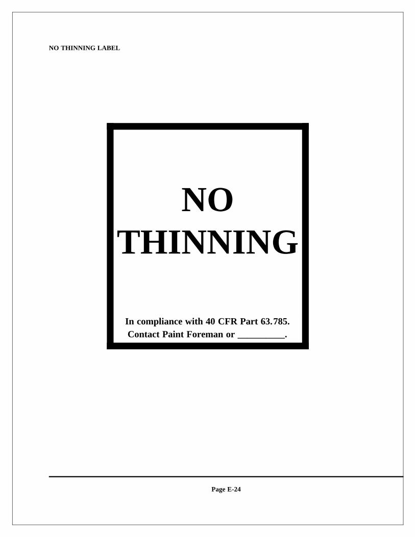
Page E-24
NO THINNING LABEL
NOTHINNING
In compliance with 40 CFR Part 63.785.Contact Paint Foreman or __________.
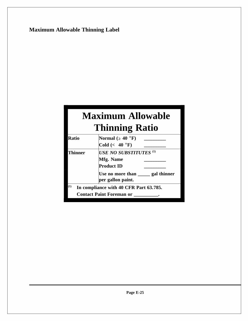
Page E-25
Maximum Allowable Thinning Label
Maximum AllowableThinning Ratio
Ratio Normal ($$ 40 EEF) _________Cold (< 40 EEF) _________
Thinner USE NO SUBSTITUTES (1)
Mfg. Name _________Product ID _________
Use no more than _____ gal thinnerper gallon paint.
In compliance with 40 CFR Part 63.785.(1)
Contact Paint Foreman or __________.
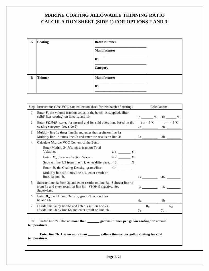
Page E-26
MARINE COATING ALLOWABLE THINNING RATIOCALCULATION SHEET (SIDE 1) FOR OPTIONS 2 AND 3
A Coating Batch Number______________________________Manufacturer______________________________ID______________________________Category______________________________
B Thinner Manufacturer______________________________ID______________________________
Step Instructions (Use VOC data collection sheet for this batch of coating) Calculations
1 Enter V the volume fraction solids in the batch, as supplied, (literS
solid/ liter coating) on lines 1a and 1b. 1a _______ % 1b ______ %
2 t $ 4.5EC t < 4.5ECEnter VOHAP LIMIT, for normal and for cold operation, based on thecoating category (see side 2) 2a _________ 2b ________
3 Multiply line 1a times line 2a and enter the results on line 3a.Multiply line 1b times line 2b and enter the results on line 3b. 3a _________ 3b ________
4 Calculate M the VOC Content of the Batchvoc
Enter Method 24 MV, mass fraction TotalVolatiles. 4.1 _______ %
Enter M the mass fraction Water.w 4.2 _______ %
Subtract line 4.2 from line 4.1, enter difference. 4.3 _______ %
Enter D the Coating Density, grams/liter.C 4.4 _______
Multiply line 4.3 times line 4.4, enter result onlines 4a and 4b. 4a _________ 4b ________
5 Subtract line 4a from 3a and enter results on line 5a. Subtract line 4bfrom 3b and enter result on line 5b. STOP if negative. SeeSupervisor.
5a _________ 5b ________
6 Enter D the Thinner Density, grams/liter, on linesth
6a and 6b. 6a_________ 6b_________
7 Divide line 5a by line 6a and enter result on line 7a . R RDivide line 5b by line 6b and enter result on line 7b.
N
7a _________ 7b ________ C
8 Enter line 7a: Use no more than _______ gallons thinner per gallon coating for normaltemperatures.
Enter line 7b: Use no more than _______ gallons thinner per gallon coating for coldtemperatures.
A Coating Batch Number______________________________Manufacturer______________________________ID______________________________Category______________________________
B Thinner Manufacturer______________________________ID______________________________
Page E-27
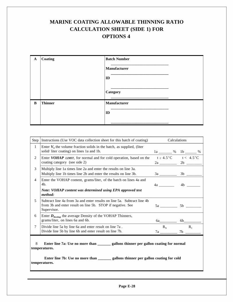
Page E-28
MARINE COATING ALLOWABLE THINNING RATIOCALCULATION SHEET (SIDE 1) FOR
OPTIONS 4
A Coating Batch Number______________________________
Manufacturer______________________________
ID
______________________________Category
______________________________
B Thinner Manufacturer______________________________
ID
______________________________
Step Instructions (Use VOC data collection sheet for this batch of coating) Calculations
1 Enter V the volume fraction solids in the batch, as supplied, (literS
solid/ liter coating) on lines 1a and 1b. 1a _______ % 1b ______ %
2 t $ 4.5EC t < 4.5ECEnter VOHAP LIMIT, for normal and for cold operation, based on thecoating category (see side 2) 2a _________ 2b ________
3 Multiply line 1a times line 2a and enter the results on line 3a.Multiply line 1b times line 2b and enter the results on line 3b. 3a _________ 3b ________
4 Enter the VOHAP content, grams/liter, of the batch on lines 4a and4b. 4a ________ 4b _______Note: VOHAP content was determined using EPA approved testmethod:
5 Subtract line 4a from 3a and enter results on line 5a. Subtract line 4bfrom 3b and enter result on line 5b. STOP if negative. SeeSupervisor.
5a _________ 5b ________
6 Enter D the average Density of the VOHAP Thinners,thvohap
grams/liter, on lines 6a and 6b. 6a_________ 6b_________
7 Divide line 5a by line 6a and enter result on line 7a . R RDivide line 5b by line 6b and enter result on line 7b.
N
7a _________ 7b ________ C
8 Enter line 7a: Use no more than _______ gallons thinner per gallon coating for normaltemperatures.
Enter line 7b: Use no more than _______ gallons thinner per gallon coating for coldtemperatures.
A Coating Batch Number______________________________
Manufacturer______________________________
ID
______________________________Category
______________________________
B Thinner Manufacturer______________________________
ID
______________________________
Page E-29
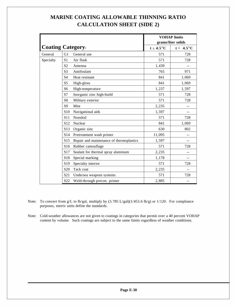
Page E-30
MARINE COATING ALLOWABLE THINNING RATIOCALCULATION SHEET (SIDE 2)
Coating Category:
VOHAP limitsgrams/liter solids
t $$ 4.5EEC t < 4.5EEC
General G1 General use 571 728
Specialty S1 Air flask 571 728
S2 Antenna 1,439 --
S3 Antifoulant 765 971
S4 Heat resistant 841 1,069
S5 High-gloss 841 1,069
S6 High-temperature 1,237 1,597
S7 Inorganic zinc high-build 571 728
S8 Military exterior 571 728
S9 Mist 2,235 --
S10 Navigational aids 1,597 --
S11 Nonskid 571 728
S12 Nuclear 841 1,069
S13 Organic zinc 630 802
S14 Pretreatment wash primer 11,095 --
S15 Repair and maintenance of thermoplastics 1,597 --
S16 Rubber camouflage 571 728
S17 Sealant for thermal spray aluminum 2,235 --
S18 Special marking 1,178 --
S19 Specialty interior 571 728
S20 Tack coat 2,235 --
S21 Undersea weapons systems 571 728
S22 Weld-through precon. primer 2,885 --
Note: To convert from g/L to lb/gal, multiply by (3.785 L/gal)(1/453.6 lb/g) or 1/120. For compliancepurposes, metric units define the standards.
Note: Cold-weather allowances are not given to coatings in categories that permit over a 40 percent VOHAPcontent by volume. Such coatings are subject to the same limits regardless of weather conditions.
Page E-31
Attachment B:MARINE COATING
DATA SHEETS
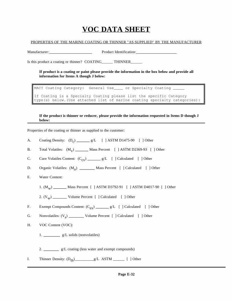
Page E-32
MACT Coating Category: General Use____ or Specialty Coating _____
If Coating is a Specialty Coating please list the specific Categorytype(s) below.(Use attached list of marine coating specialty categories):
VOC DATA SHEETPROPERTIES OF THE MARINE COATING OR THINNER "AS SUPPLIED" BY THE MANUFACTURER
Manufacturer: Product Identification:
Is this product a coating or thinner? COATING______ THINNER______
If product is a coating or paint please provide the information in the box below and provide allinformation for Items A though J below:
If the product is thinner or reducer, please provide the information requested in Items D though Jbelow:
Properties of the coating or thinner as supplied to the customer:
A. Coating Density: (D ) g/L [ ] ASTM D1475-90 [ ] Otherc
B. Total Volatiles: (M ) Mass Percent [ ] ASTM D2369-93 [ ] Otherv
C. Cure Volatiles Content: (C ) g/L [ ] Calculated [ ] Othercv
D. Organic Volatiles: (M ) Mass Percent [ ] Calculated [ ] Othero
E. Water Content:
1. (M ) Mass Percent [ ] ASTM D3792-91 [ ] ASTM D4017-90 [ ] Otherw
2. (V ) Volume Percent [ ] Calculated [ ] Otherw
F. Exempt Compounds Content: (C ) g/L [ ] Calculated [ ] Otherex
G. Nonvolatiles: (V ) Volume Percent [ ] Calculated [ ] Others
H. VOC Content (VOC):
1. g/L solids (nonvolatiles)
2. g/L coating (less water and exempt compounds)
I. Thinner Density: (D )__________g/L ASTM ______ [ ] Otherth
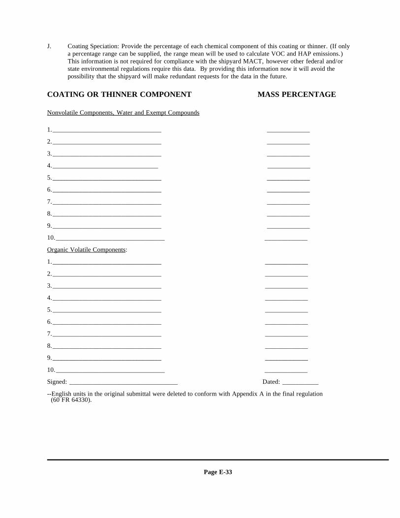
Page E-33
J. Coating Speciation: Provide the percentage of each chemical component of this coating or thinner. (If onlya percentage range can be supplied, the range mean will be used to calculate VOC and HAP emissions.) This information is not required for compliance with the shipyard MACT, however other federal and/orstate environmental regulations require this data. By providing this information now it will avoid thepossibility that the shipyard will make redundant requests for the data in the future.
COATING OR THINNER COMPONENT MASS PERCENTAGE
Nonvolatile Components, Water and Exempt Compounds
1._________________________________ _____________
2._________________________________ _____________
3._________________________________ _____________
4.________________________________ _____________
5._________________________________ _____________
6._________________________________ _____________
7._________________________________ _____________
8._________________________________ _____________
9._________________________________ _____________
10._________________________________ _____________
Organic Volatile Components:
1._________________________________ _____________
2._________________________________ _____________
3._________________________________ _____________
4._________________________________ _____________
5._________________________________ _____________
6._________________________________ _____________
7._________________________________ _____________
8._________________________________ _____________
9._________________________________ _____________
10._________________________________ _____________
Signed: _________________________________ Dated: ___________
--English units in the original submittal were deleted to conform with Appendix A in the final regulation (60 FR 64330).
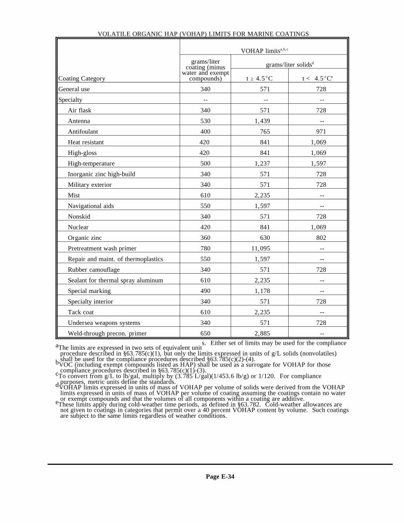
Page E-34
VOLATILE ORGANIC HAP (VOHAP) LIMITS FOR MARINE COATINGS
Coating Category
VOHAP limitsa,b,c
grams/litercoating (minus
water and exemptcompounds)
grams/liter solidsd
t $ 4.5EC t < 4.5ECe
General use 340 571 728
Specialty -- -- --
Air flask 340 571 728
Antenna 530 1,439 --
Antifoulant 400 765 971
Heat resistant 420 841 1,069
High-gloss 420 841 1,069
High-temperature 500 1,237 1,597
Inorganic zinc high-build 340 571 728
Military exterior 340 571 728
Mist 610 2,235 --
Navigational aids 550 1,597 --
Nonskid 340 571 728
Nuclear 420 841 1,069
Organic zinc 360 630 802
Pretreatment wash primer 780 11,095 --
Repair and maint. of thermoplastics 550 1,597 --
Rubber camouflage 340 571 728
Sealant for thermal spray aluminum 610 2,235 --
Special marking 490 1,178 --
Specialty interior 340 571 728
Tack coat 610 2,235 --
Undersea weapons systems 340 571 728
Weld-through precon. primer 650 2,885 -- s. Either set of limits may be used for the complianceaThe limits are expressed in two sets of equivalent unit
procedure described in §63.785(c)(1), but only the limits expressed in units of g/L solids (nonvolatiles)shall be used for the compliance procedures described §63.785(c)(2)-(4).VOC (including exempt compounds listed as HAP) shall be used as a surrogate for VOHAP for thosebcompliance procedures described in §63.785(c)(1)-(3).To convert from g/L to lb/gal, multiply by (3.785 L/gal)(1/453.6 lb/g) or 1/120. For compliancecpurposes, metric units define the standards.VOHAP limits expressed in units of mass of VOHAP per volume of solids were derived from the VOHAPdlimits expressed in units of mass of VOHAP per volume of coating assuming the coatings contain no wateror exempt compounds and that the volumes of all components within a coating are additive.These limits apply during cold-weather time periods, as defined in §63.782. Cold-weather allowances areenot given to coatings in categories that permit over a 40 percent VOHAP content by volume. Such coatingsare subject to the same limits regardless of weather conditions.
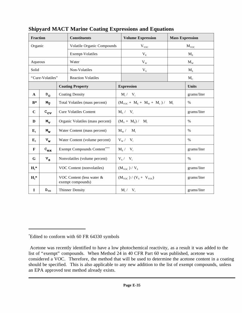
Edited to conform with 60 FR 64330 symbols*
Acetone was recently identified to have a low photochemical reactivity, as a result it was added to thelist of “exempt” compounds. When Method 24 in 40 CFR Part 60 was published, acetone wasconsidered a VOC. Therefore, the method that will be used to determine the acetone content in a coatingshould be specified. This is also applicable to any new addition to the list of exempt compounds, unlessan EPA approved test method already exists.
Page E-35
Shipyard MACT Marine Coating Expressions and EquationsFraction Constituents Volume Expression Mass Expression
Organic Volatile Organic Compounds V MVOC VOC
Exempt-Volatiles V ME E
Aqueous Water V MW W
Solid Non-Volatiles V MS S
“Cure-Volatiles” Reaction Volatiles MC
Coating Property Expression Units
A Dc Coating Density 3M / 3V grams/literi i
B* MT Total Volatiles (mass percent) (M + M + M + M ) / 3M %VOC E W c i
C Ccv Cure Volatiles Content M / 3V grams/literC i
D Mv Organic Volatiles (mass percent) (M + M ) / 3M %V E i
E1 Mw Water Content (mass percent) M / 3 M %W i
E2 Vw Water Content (volume percent) V / 3V %W i
F Cex Exempt Compounds Content M / 3V grams/liter****E i
G Vs Nonvolatiles (volume percent) V / 3V %S i
H *1 VOC Content (nonvolatiles) (M ) / V grams/literVOC S
H *2 VOC Content (less water & (M ) / (V + V ) grams/literexempt compounds)
VOC S VOC
I DTH Thinner Density 3M / 3V grams/literi i

Page E-36
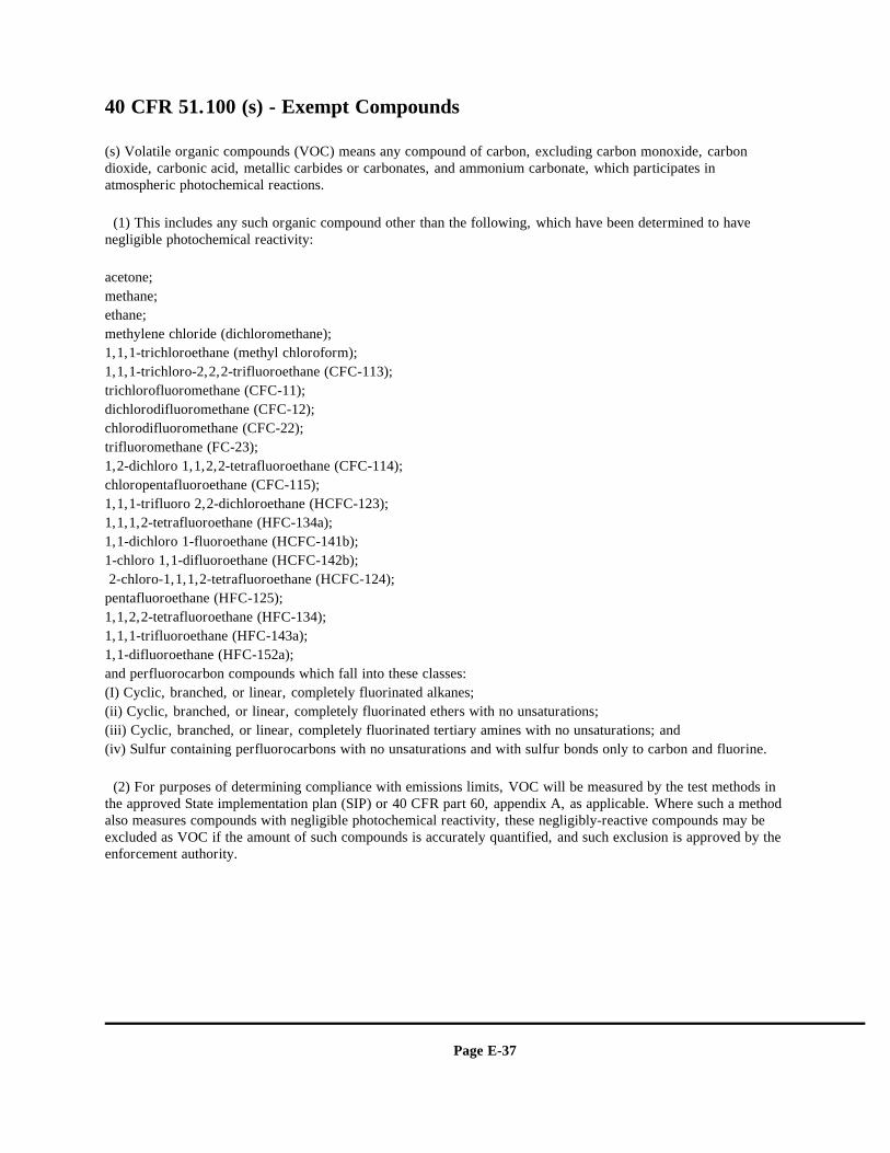
Page E-37
40 CFR 51.100 (s) - Exempt Compounds
(s) Volatile organic compounds (VOC) means any compound of carbon, excluding carbon monoxide, carbondioxide, carbonic acid, metallic carbides or carbonates, and ammonium carbonate, which participates inatmospheric photochemical reactions.
(1) This includes any such organic compound other than the following, which have been determined to havenegligible photochemical reactivity:
acetone; methane; ethane; methylene chloride (dichloromethane); 1,1,1-trichloroethane (methyl chloroform); 1,1,1-trichloro-2,2,2-trifluoroethane (CFC-113); trichlorofluoromethane (CFC-11); dichlorodifluoromethane (CFC-12); chlorodifluoromethane (CFC-22); trifluoromethane (FC-23); 1,2-dichloro 1,1,2,2-tetrafluoroethane (CFC-114); chloropentafluoroethane (CFC-115); 1,1,1-trifluoro 2,2-dichloroethane (HCFC-123); 1,1,1,2-tetrafluoroethane (HFC-134a); 1,1-dichloro 1-fluoroethane (HCFC-141b); 1-chloro 1,1-difluoroethane (HCFC-142b); 2-chloro-1,1,1,2-tetrafluoroethane (HCFC-124); pentafluoroethane (HFC-125); 1,1,2,2-tetrafluoroethane (HFC-134); 1,1,1-trifluoroethane (HFC-143a);1,1-difluoroethane (HFC-152a); and perfluorocarbon compounds which fall into these classes:(I) Cyclic, branched, or linear, completely fluorinated alkanes;(ii) Cyclic, branched, or linear, completely fluorinated ethers with no unsaturations;(iii) Cyclic, branched, or linear, completely fluorinated tertiary amines with no unsaturations; and(iv) Sulfur containing perfluorocarbons with no unsaturations and with sulfur bonds only to carbon and fluorine.
(2) For purposes of determining compliance with emissions limits, VOC will be measured by the test methods inthe approved State implementation plan (SIP) or 40 CFR part 60, appendix A, as applicable. Where such a methodalso measures compounds with negligible photochemical reactivity, these negligibly-reactive compounds may beexcluded as VOC if the amount of such compounds is accurately quantified, and such exclusion is approved by theenforcement authority.
Page E-38
Attachment C:COATING DEFINITIONS
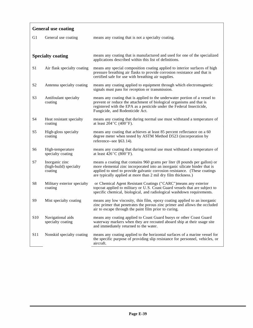
Page E-39
General use coating
G1 General use coating means any coating that is not a specialty coating.
Specialty coating means any coating that is manufactured and used for one of the specializedapplications described within this list of definitions.
S1 Air flask specialty coating means any special composition coating applied to interior surfaces of highpressure breathing air flasks to provide corrosion resistance and that iscertified safe for use with breathing air supplies.
S2 Antenna specialty coating means any coating applied to equipment through which electromagneticsignals must pass for reception or transmission.
S3 Antifoulant specialty means any coating that is applied to the underwater portion of a vessel tocoating prevent or reduce the attachment of biological organisms and that is
registered with the EPA as a pesticide under the Federal Insecticide,Fungicide, and Rodenticide Act.
S4 Heat resistant specialty means any coating that during normal use must withstand a temperature ofcoating at least 204EC (400EF).
S5 High-gloss specialty means any coating that achieves at least 85 percent reflectance on a 60coating degree meter when tested by ASTM Method D523 (incorporation by
reference--see §63.14).
S6 High-temperature means any coating that during normal use must withstand a temperature ofspecialty coating at least 426EC (800EF).
S7 Inorganic zinc means a coating that contains 960 grams per liter (8 pounds per gallon) or(high-build) specialty more elemental zinc incorporated into an inorganic silicate binder that iscoating applied to steel to provide galvanic corrosion resistance. (These coatings
are typically applied at more than 2 mil dry film thickness.)
S8 Military exterior specialty or Chemical Agent Resistant Coatings ("CARC")means any exteriorcoating topcoat applied to military or U.S. Coast Guard vessels that are subject to
specific chemical, biological, and radiological washdown requirements.
S9 Mist specialty coating means any low viscosity, thin film, epoxy coating applied to an inorganiczinc primer that penetrates the porous zinc primer and allows the occludedair to escape through the paint film prior to curing.
S10 Navigational aids means any coating applied to Coast Guard buoys or other Coast Guardspecialty coating waterway markers when they are recoated aboard ship at their usage site
and immediately returned to the water.
S11 Nonskid specialty coating means any coating applied to the horizontal surfaces of a marine vessel forthe specific purpose of providing slip resistance for personnel, vehicles, oraircraft.
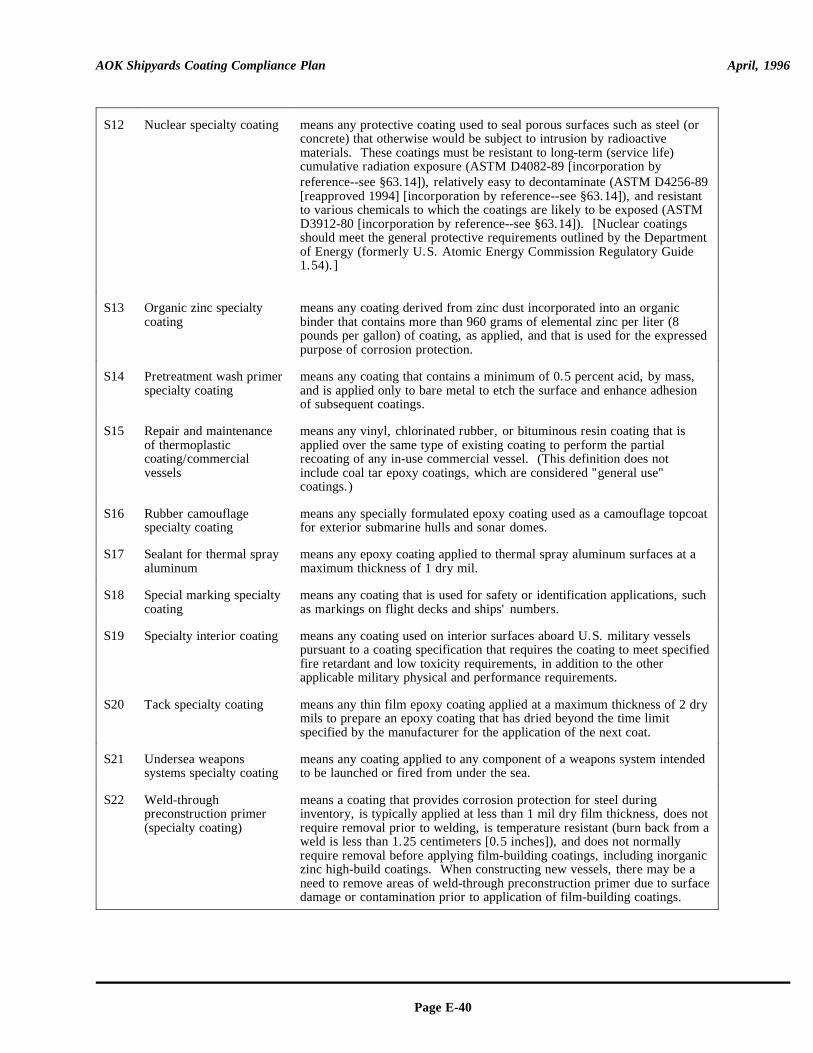
AOK Shipyards Coating Compliance Plan April, 1996
Page E-40
S12 Nuclear specialty coating means any protective coating used to seal porous surfaces such as steel (orconcrete) that otherwise would be subject to intrusion by radioactivematerials. These coatings must be resistant to long-term (service life)cumulative radiation exposure (ASTM D4082-89 [incorporation byreference--see §63.14]), relatively easy to decontaminate (ASTM D4256-89[reapproved 1994] [incorporation by reference--see §63.14]), and resistantto various chemicals to which the coatings are likely to be exposed (ASTMD3912-80 [incorporation by reference--see §63.14]). [Nuclear coatingsshould meet the general protective requirements outlined by the Departmentof Energy (formerly U.S. Atomic Energy Commission Regulatory Guide1.54).]
S13 Organic zinc specialty means any coating derived from zinc dust incorporated into an organiccoating binder that contains more than 960 grams of elemental zinc per liter (8
pounds per gallon) of coating, as applied, and that is used for the expressedpurpose of corrosion protection.
S14 Pretreatment wash primer means any coating that contains a minimum of 0.5 percent acid, by mass,specialty coating and is applied only to bare metal to etch the surface and enhance adhesion
of subsequent coatings.
S15 Repair and maintenance means any vinyl, chlorinated rubber, or bituminous resin coating that isof thermoplastic applied over the same type of existing coating to perform the partialcoating/commercial recoating of any in-use commercial vessel. (This definition does notvessels include coal tar epoxy coatings, which are considered "general use"
coatings.)
S16 Rubber camouflage means any specially formulated epoxy coating used as a camouflage topcoatspecialty coating for exterior submarine hulls and sonar domes.
S17 Sealant for thermal spray means any epoxy coating applied to thermal spray aluminum surfaces at aaluminum maximum thickness of 1 dry mil.
S18 Special marking specialty means any coating that is used for safety or identification applications, suchcoating as markings on flight decks and ships' numbers.
S19 Specialty interior coating means any coating used on interior surfaces aboard U.S. military vesselspursuant to a coating specification that requires the coating to meet specifiedfire retardant and low toxicity requirements, in addition to the otherapplicable military physical and performance requirements.
S20 Tack specialty coating means any thin film epoxy coating applied at a maximum thickness of 2 drymils to prepare an epoxy coating that has dried beyond the time limitspecified by the manufacturer for the application of the next coat.
S21 Undersea weapons means any coating applied to any component of a weapons system intendedsystems specialty coating to be launched or fired from under the sea.
S22 Weld-through means a coating that provides corrosion protection for steel duringpreconstruction primer inventory, is typically applied at less than 1 mil dry film thickness, does not(specialty coating) require removal prior to welding, is temperature resistant (burn back from a
weld is less than 1.25 centimeters [0.5 inches]), and does not normallyrequire removal before applying film-building coatings, including inorganiczinc high-build coatings. When constructing new vessels, there may be aneed to remove areas of weld-through preconstruction primer due to surfacedamage or contamination prior to application of film-building coatings.

Page F-1
APPENDIX F
EXAMPLE FORMS
AOK Shipyards Coating Compliance Plan April, 1996
Page F-2
THIS PAGE INTENTIONALLY LEFT BLANK
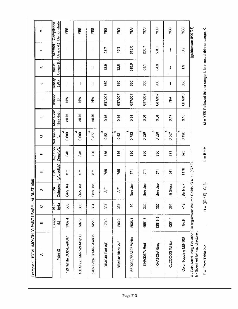
Page F-3
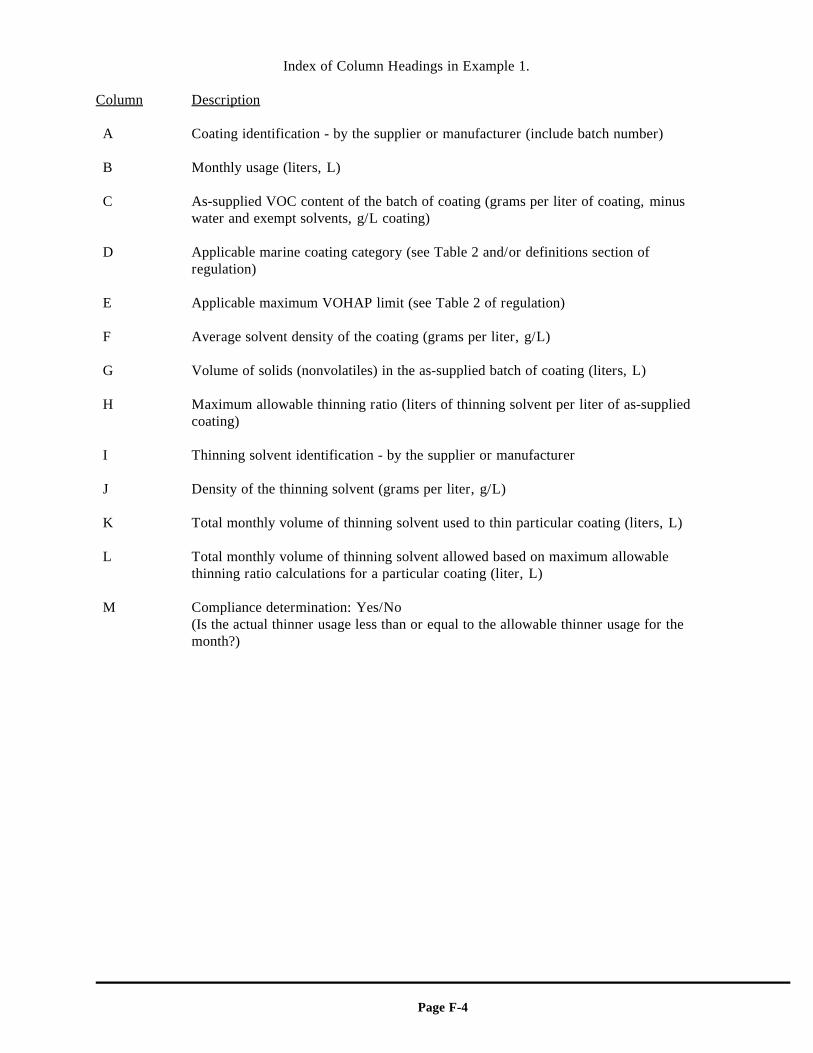
Page F-4
Index of Column Headings in Example 1.
Column Description
A Coating identification - by the supplier or manufacturer (include batch number)
B Monthly usage (liters, L)
C As-supplied VOC content of the batch of coating (grams per liter of coating, minuswater and exempt solvents, g/L coating)
D Applicable marine coating category (see Table 2 and/or definitions section ofregulation)
E Applicable maximum VOHAP limit (see Table 2 of regulation)
F Average solvent density of the coating (grams per liter, g/L)
G Volume of solids (nonvolatiles) in the as-supplied batch of coating (liters, L)
H Maximum allowable thinning ratio (liters of thinning solvent per liter of as-suppliedcoating)
I Thinning solvent identification - by the supplier or manufacturer
J Density of the thinning solvent (grams per liter, g/L)
K Total monthly volume of thinning solvent used to thin particular coating (liters, L)
L Total monthly volume of thinning solvent allowed based on maximum allowablethinning ratio calculations for a particular coating (liter, L)
M Compliance determination: Yes/No(Is the actual thinner usage less than or equal to the allowable thinner usage for themonth?)
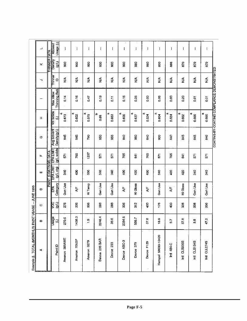
Page F-5
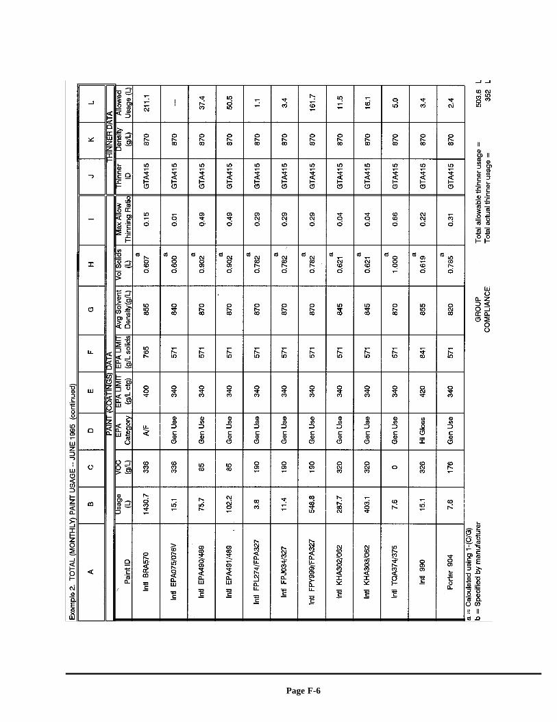
Page F-6
Page G-1
APPENDIX G
EXAMPLE CALCULATIONS

Page G-2

Page G-3

Page G-4

Page G-5
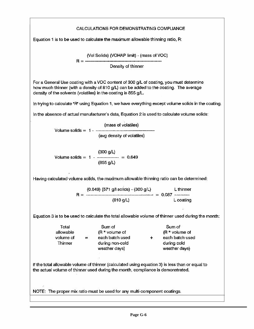
Page G-6

Page G-7
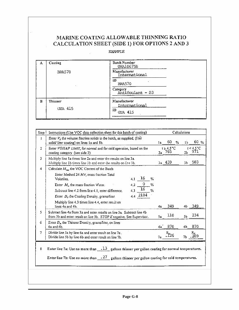
Page G-8

Page G-9
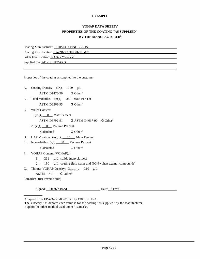
Page G-10
EXAMPLE
VOHAP DATA SHEET:1
PROPERTIES OF THE COATING "AS SUPPLIED"
BY THE MANUFACTURER2
Coating Manufacturer: SHIP-COATINGS-R-US
Coating Identification: 1A-2B-3C (HIGH-TEMP)
Batch Identification: XXX-YYY-ZZZ
Supplied To: AOK SHIPYARD
Properties of the coating as supplied to the customer:2
A. Coating Density: (D ) 1000 g/Lc s
ASTM D1475-90 G Other: 3
B. Total Volatiles: (m ) 35 Mass Percentv s
ASTM D2369-93 G Other: 3
C. Water Content:
1. (m ) 0 Mass Percentw s
ASTM D3792-91 G ASTM D4017-90 G Other: 3
2. (v ) 0 Volume Percentw s
Calculated G Other: 3
D. HAP Volatiles: (m ) 15 Mass PercentHAP s
E. Nonvolatiles: (v ) 38 Volume Percentn s
Calculated G Other: 3
F. VOHAP Content (VOHAP) : s
1. 231 g/L solids (nonvolatiles)
2. 150 g/L coating (less water and NON-vohap exempt compounds)
G. Thinner VOHAP Density: D 310 g/Lth(VOHAP)
ASTM 319 G Other3
Remarks: (use reverse side)
Signed: Debbie Bond Date: 9/17/96
Adapted from EPA-340/1-86-016 (July 1986), p. II-2.1
The subscript "s" denotes each value is for the coating "as supplied" by the manufacturer.2
Explain the other method used under "Remarks."3
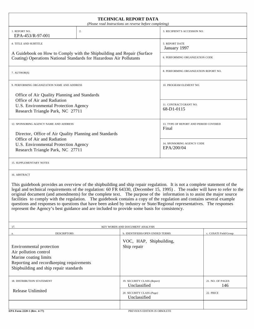
TECHNICAL REPORT DATA(Please read Instructions on reverse before completing)
1. REPORT NO. 2. 3. RECIPIENT'S ACCESSION NO.
EPA-453/R-97-001
4. TITLE AND SUBTITLE 5. REPORT DATE
A Guidebook on How to Comply with the Shipbuilding and Repair (SurfaceCoating) Operations National Standards for Hazardous Air Pollutants
January 1997
6. PERFORMING ORGANIZATION CODE
7. AUTHOR(S) 8. PERFORMING ORGANIZATION REPORT NO.
9. PERFORMING ORGANIZATION NAME AND ADDRESS 10. PROGRAM ELEMENT NO.
Office of Air Quality Planning and Standards Office of Air and Radiation U.S. Environmental Protection Agency Research Triangle Park, NC 27711
11. CONTRACT/GRANT NO.
68-D1-0115
12. SPONSORING AGENCY NAME AND ADDRESS 13. TYPE OF REPORT AND PERIOD COVERED
Director, Office of Air Quality Planning and Standards Office of Air and Radiation U.S. Environmental Protection Agency Research Triangle Park, NC 27711
Final
14. SPONSORING AGENCY CODE
EPA/200/04
15. SUPPLEMENTARY NOTES
16. ABSTRACT
This guidebook provides an overview of the shipbuilding and ship repair regulation. It is not a complete statement of thelegal and technical requirements of the regulation: 60 FR 64330, (December 15, 1995) . The reader will have to refer to theoriginal document (and amendments) for the complete text. The purpose of the information is to assist the major sourcefacilities to comply with the regulation. The guidebook contains a copy of the regulation and contains several examplequestions and responses to questions that have been asked by industry or State/Regional representatives. The responsesrepresent the Agency’s best guidance and are included to provide some basis for consistency.
17. KEY WORDS AND DOCUMENT ANALYSIS
a. DESCRIPTORS b. IDENTIFIERS/OPEN ENDED TERMS c. COSATI Field/Group
Environmental protection Ship repairAir pollution controlMarine coating limitsReporting and recordkeeping requirementsShipbuilding and ship repair standards
VOC, HAP, Shipbuilding,
18. DISTRIBUTION STATEMENT 19. SECURITY CLASS (Report) 21. NO. OF PAGES
Release Unlimited Unclassified 146
20. SECURITY CLASS (Page) 22. PRICE
Unclassified
EPA Form 2220-1 (Rev. 4-77) PREVIOUS EDITION IS OBSOLETE
Appendix D
Standard Methods for Testing and Collecting Samples:
Method 24 – Determination of Volatile Matter Content, Water Content, Density, Volume Solids, and Weight Solids of Surface
Coatings
Standard Procedure for Collection of Coating and Ink Samples
for Analysis by Reference Methods 24 and 24A
1180
METHOD 24 - DETERMINATION OF VOLATILE MATTER CONTENT,WATER CONTENT, DENSITY, VOLUME SOLIDS, AND
WEIGHT SOLIDS OF SURFACE COATINGS
1.0 Scope and Application.
1.1 Analytes.
Analyte CAS No.
Volatile organic compounds No CAS Number assigned
Water 7732-18-5
1.2 Applicability. This method is applicable for the
determination of volatile matter content, water content,
density, volume solids, and weight solids of paint, varnish,
lacquer, or other related surface coatings.
1.3 Precision and Bias. Intra- and inter-laboratory
analytical precision statements are presented in Section
13.1. No bias has been identified.
2.0 Summary of Method.
2.1 Standard methods are used to determine the
volatile matter content, water content, density, volume
solids, and weight solids of paint, varnish, lacquer, or
other related surface coatings.
3.0 Definitions.
3.1 Waterborne coating means any coating which
contains more than 5 percent water by weight in its volatile
fraction.
1181
3.2 Multicomponent coatings are coatings that are
packaged in two or more parts, which are combined before
application. Upon combination a coreactant from one part of
the coating chemically reacts, at ambient conditions, with a
coreactant from another part of the coating.
3.3 Ultraviolet (UV) radiation-cured coatings are
coatings which contain unreacted monomers that are
polymerized by exposure to ultraviolet light.
4.0 Interferences. [Reserved]
5.0 Safety.
5.1 Disclaimer. This method may involve hazardous
materials, operations, and equipment. This test method may
not address all of the safety problems associated with its
use. It is the responsibility of the user of this test
method to establish appropriate safety and health practices
and to determine the applicability of regulatory limitations
prior to performing this test method.
5.2 Hazardous Components. Several of the compounds
that may be contained in the coatings analyzed by this
method may be irritating or corrosive to tissues (e.g.,
heptane) or may be toxic (e.g., benzene, methyl alcohol).
Nearly all are fire hazards. Appropriate precautions can be
found in reference documents, such as Reference 3 of Section
16.0.
1182
6.0 Equipment and Supplies.
The equipment and supplies specified in the ASTM
methods listed in Sections 6.1 through 6.6 (incorporated by
reference - see § 60.17 for acceptable versions of the
methods) are required:
6.1 ASTM D 1475-60, 80, or 90, Standard Test Method
for Density of Paint, Varnish, Lacquer, and Related
Products.
6.2 ASTM D 2369-81, 87, 90, 92, 93, or 95, Standard
Test Method for Volatile Content of Coatings.
6.3 ASTM D 3792-79 or 91, Standard Test Method for
Water Content of Water Reducible Paints by Direct Injection
into a Gas Chromatograph.
6.4 ASTM D 4017-81, 90, or 96a, Standard Test Method
for Water in Paints and Paint Materials by the Karl Fischer
Titration Method.
6.5 ASTM 4457-85 (Reapproved 1991), Standard Test
Method for Determination of Dichloromethane and 1,1,1-
Trichloroethane in Paints and Coatings by Direct Injection
into a Gas Chromatograph.
6.6 ASTM D 5403-93, Standard Test Methods for
Volatile Content of Radiation Curable Materials.
7.0 Reagents and Standards.
1183
7.1 The reagents and standards specified in the ASTM
methods listed in Sections 6.1 through 6.6 are required.
8.0 Sample Collection, Preservation, Storage, and
Transport.
8.1 Follow the sample collection, preservation,
storage, and transport procedures described in Reference 1
of Section 16.0.
9.0 Quality Control.
9.1 Reproducibility (NOTE: Not applicable to UV
radiation-cured coatings). The variety of coatings that may
be subject to analysis makes it necessary to verify the
ability of the analyst and the analytical procedures to
obtain reproducible results for the coatings tested.
Verification is accomplished by running duplicate analyses
on each sample tested (Sections 11.2 through 11.4) and
comparing the results with the intra-laboratory precision
statements (Section 13.1) for each parameter.
9.2 Confidence Limits for Waterborne Coatings.
Because of the inherent increased imprecision in the
determination of the VOC content of waterborne coatings as
the weight percent of water increases, measured parameters
for waterborne coatings are replaced with appropriate
confidence limits (Section 12.6). These confidence limits
1184
are based on measured parameters and inter-laboratory
precision statements.
10.0 Calibration and Standardization.
10.1 Perform the calibration and standardization
procedures specified in the ASTM methods listed in Sections
6.1 through 6.6.
11.0 Analytical Procedure.
Additional guidance can be found in Reference 2 of
Section 16.0.
11.1 Non Thin-film Ultraviolet Radiation-cured (UV
radiation-cured) Coatings.
11.1.1 Volatile Content. Use the procedure in ASTM D
5403 to determine the volatile matter content of the coating
except the curing test described in NOTE 2 of ASTM D 5403 is
required.
11.1.2 Water Content. To determine water content,
follow Section 11.3.2.
11.1.3 Coating Density. To determine coating
density, follow Section 11.3.3.
11.1.4 Solids Content. To determine solids content,
follow Section 11.3.4.
11.1.5 To determine if a coating or ink can be
classified as a thin-film UV cured coating or ink, use the
equation in Section 12.2. If C is less than 0.2 g and A is
1185
greater than or equal to 225 cm2 (35 in2) then the coating
or ink is considered a thin-film UV radiation-cured coating
and ASTM D 5403 is not applicable.
NOTE: As noted in Section 1.4 of ASTM D 5403, this
method may not be applicable to radiation curable materials
wherein the volatile material is water.
11.2 Multi-component Coatings.
11.2.1 Sample Preparation.
11.2.1.1 Prepare about 100 ml of sample by mixing the
components in a storage container, such as a glass jar with
a screw top or a metal can with a cap. The storage
container should be just large enough to hold the mixture.
Combine the components (by weight or volume) in the ratio
recommended by the manufacturer. Tightly close the
container between additions and during mixing to prevent
loss of volatile materials. However, most manufacturers
mixing instructions are by volume. Because of possible
error caused by expansion of the liquid when measuring the
volume, it is recommended that the components be combined by
weight. When weight is used to combine the components and
the manufacturer’s recommended ratio is by volume, the
density must be determined by Section 11.3.3.
1186
11.2.1.2 Immediately after mixing, take aliquots from
this 100 ml sample for determination of the total volatile
content, water content, and density.
11.2.2 Volatile Content. To determine total volatile
content, use the apparatus and reagents described in ASTM
D2369 Sections 3 and 4 (incorporated by reference - see §
60.17 for the approved versions of the standard),
respectively, and use the following procedures:
11.2.2.1 Weigh and record the weight of an aluminum
foil weighing dish. Add 3 + 1 ml of suitable solvent as
specified in ASTM D2369 to the weighing dish. Using a
syringe as specified in ASTM D2369, weigh to 1 mg, by
difference, a sample of coating into the weighing dish. For
coatings believed to have a volatile content less than 40
weight percent, a suitable size is 0.3 + 0.10 g, but for
coatings believed to have a volatile content greater than 40
weight percent, a suitable size is 0.5 + 0.1 g.
NOTE: If the volatile content determined pursuant to
Section 12.4 is not in the range corresponding to the sample
size chosen repeat the test with the appropriate sample
size. Add the specimen dropwise, shaking (swirling) the
dish to disperse the specimen completely in the solvent. If
the material forms a lump that cannot be dispersed, discard
the specimen and prepare a new one. Similarly, prepare a
1187
duplicate. The sample shall stand for a minimum of 1 hour,
but no more than 24 hours prior to being oven cured at
110 + 5EC (230 + 9EF) for 1 hour.
11.2.2.2 Heat the aluminum foil dishes containing the
dispersed specimens in the forced draft oven for 60 min at
110 + 5EC (230 + 9EF). Caution -- provide adequate
ventilation, consistent with accepted laboratory practice,
to prevent solvent vapors from accumulating to a dangerous
level.
11.2.2.3 Remove the dishes from the oven, place
immediately in a desiccator, cool to ambient temperature,
and weigh to within 1 mg.
11.2.2.4 Run analyses in pairs (duplicate sets) for
each coating mixture until the criterion in Section 11.4 is
met. Calculate Wv following Equation 24-2 and record the
arithmetic average.
11.2.3 Water Content. To determine water content,
follow Section 11.3.2.
11.2.4 Coating Density. To determine coating
density, follow Section 11.3.3.
11.2.5 Solids Content. To determine solids content,
follow Section 11.3.4.
11.2.6 Exempt Solvent Content. To determine the
exempt solvent content, follow Section 11.3.5.
1188
NOTE: For all other coatings (i.e., water- or
solvent-borne coatings) not covered by multicomponent or UV
radiation-cured coatings, analyze as shown below:
11.3 Water- or Solvent-borne coatings.
11.3.1 Volatile Content. Use the procedure in ASTM D
2369 to determine the volatile matter content (may include
water) of the coating.
11.3.1.1 Record the following information:
W1 = weight of dish and sample before heating, g
W2 = weight of dish and sample after heating, g
W3 = sample weight, g.
11.3.1.2 Calculate the weight fraction of the
volatile matter (Wv) for each analysis as shown in Section
12.3.
11.3.1.3 Run duplicate analyses until the difference
between the two values in a set is less than or equal to the
intra-laboratory precision statement in Section 13.1.
11.3.1.4 Record the arithmetic average (W̄v).
11.3.2 Water Content. For waterborne coatings only,
determine the weight fraction of water (Ww) using either
ASTM D 3792 or ASTM D 4017.
11.3.2.1 Run duplicate analyses until the difference
between the two values in a set is less than or equal to the
intra-laboratory precision statement in Section 13.1.
1189
11.3.2.2 Record the arithmetic average (W̄w).
11.3.3 Coating Density. Determine the density (Dc,
kg/l) of the surface coating using the procedure in ASTM D
1475.
11.3.3.1 Run duplicate analyses until each value in a
set deviates from the mean of the set by no more than the
intra-laboratory precision statement in Section 13.1.
11.3.3.2 Record the arithmetic average (D̄c).
11.3.4 Solids Content. Determine the volume fraction
(Vs) solids of the coating by calculation using the
manufacturer's formulation.
11.3.5 Exempt Solvent Content. Determine the weight
fraction of exempt solvents (WE) by using ASTM Method D4457.
Run a duplicate set of determinations and record the
arithmetic average (WE).
11.4 Sample Analysis Criteria. For Wv and Ww, run
duplicate analyses until the difference between the two
values in a set is less than or equal to the intra-
laboratory precision statement for that parameter. For Dc,
run duplicate analyses until each value in a set deviates
from the mean of the set by no more than the intra-
laboratory precision statement. If, after several attempts,
it is concluded that the ASTM procedures cannot be used for
the specific coating with the established intra-laboratory
precision (excluding UV radiation-cured coatings), the U.S.
1190
C ' F A Dc Eq. 24-1
Environmental Protection Agency (EPA) will assume
responsibility for providing the necessary procedures for
revising the method or precision statements upon written
request to: Director, Emissions, Monitoring, and Analysis
Division, MD-14, Office of Air Quality Planning and
Standards, U.S. Environmental Protection Agency, Research
Triangle Park, NC 27711.
12.0 Calculations and Data Analysis.
12.1 Nomenclature.
A = Area of substrate, cm2, (in2).
C = Amount of coating or ink added to the substrate,
g.
Dc = Density of coating or ink, g/cm3 (g/in3).
F = Manufacturer’s recommended film thickness, cm
(in).
Wo = Weight fraction of nonaqueous volatile matter,
g/g.
Ws = Weight fraction of solids, g/g.
Wv = Weight fraction of the volatile matter, g/g.
Ww = Weight fraction of the water, g/g.
12.2 To determine if a coating or ink can be
classified as a thin-film UV cured coating or ink, use the
following equation:
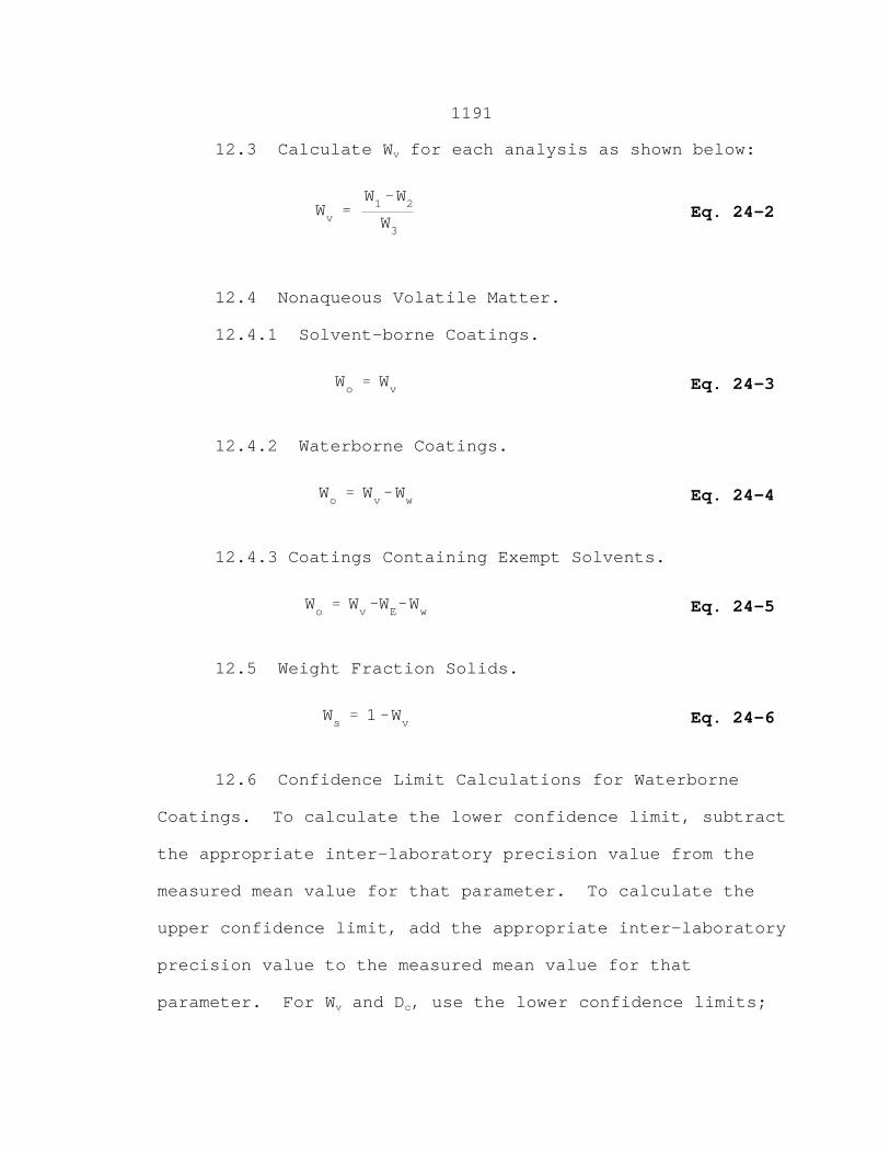
1191
Wv 'W1&W2W3
Eq. 24-2
Wo ' Wv Eq. 24-3
Wo ' Wv&Ww Eq. 24-4
Wo ' Wv&WE&Ww Eq. 24-5
Ws ' 1&Wv Eq. 24-6
12.3 Calculate Wv for each analysis as shown below:
12.4 Nonaqueous Volatile Matter.
12.4.1 Solvent-borne Coatings.
12.4.2 Waterborne Coatings.
12.4.3 Coatings Containing Exempt Solvents.
12.5 Weight Fraction Solids.
12.6 Confidence Limit Calculations for Waterborne
Coatings. To calculate the lower confidence limit, subtract
the appropriate inter-laboratory precision value from the
measured mean value for that parameter. To calculate the
upper confidence limit, add the appropriate inter-laboratory
precision value to the measured mean value for that
parameter. For Wv and Dc, use the lower confidence limits;
1192
for Ww, use the upper confidence limit. Because Ws is
calculated, there is no adjustment for this parameter.
13.0 Method Performance.
13.1 Analytical Precision Statements. The intra- and
inter-laboratory precision statements are given in Table
24-1 in Section 17.0.
14.0 Pollution Prevention. [Reserved]
15.0 Waste Management. [Reserved]
16.0 References.
Same as specified in Section 6.0, with the addition of
the following:
1. Standard Procedure for Collection of Coating and
Ink Samples for Analysis by Reference Methods 24 and 24A.
EPA-340/1-91-010. U.S. Environmental Protection Agency,
Stationary Source Compliance Division, Washington, D.C.
September 1991.
2. Standard Operating Procedure for Analysis of
Coating and Ink Samples by Reference Methods 24 and 24A.
EPA-340/1-91-011. U.S. Environmental Protection Agency,
Stationary Source Compliance Division, Washington, D.C.
September 1991.
3. Handbook of Hazardous Materials: Fire, Safety,
Health. Alliance of American Insurers. Schaumberg, IL.
1983.

1193
17.0 Tables, Diagrams, Flowcharts, and Validation Data.
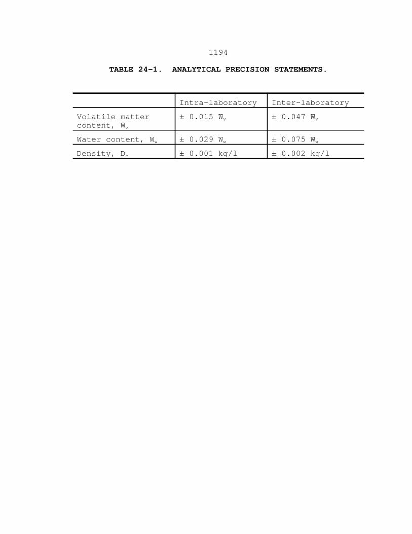
1194
TABLE 24-1. ANALYTICAL PRECISION STATEMENTS.
Intra-laboratory Inter-laboratory
Volatile mattercontent, Wv
± 0.015 W̄v ± 0.047 W̄v
Water content, Ww ± 0.029 W̄w ± 0.075 W̄w
Density, Dc ± 0.001 kg/l ± 0.002 kg/l
United States Air Quality and Planning EPA340ll-91-010 September 1991 Environmental Protec!on Standards
Agency
&Ep!!i Standard Procedure For Collection of Coating and Ink Samples For Analysis By Reference Methods 24 and 24A
@ Printed on Recycled Paper

,
EPA-340/1-91-010 -
STANDARD PROCEDURE FOR COLLECTION OF COATING AND INK SAMPLES FOR ANALYSIS BY REFERENCE METHODS 24 AND 24A
U.S. ENVIRONMENTAL PROTECTION AGENCY Office of Air and Radiation
Office of Air Quality Planning and Standards Stationary Source Compliance Division
Washington, DC 20460
September 1991
DISCLAIMER
This document is a draft report submitted to the Stationary Source Compliance Division for circulation and subsequent comment on the technical adequacy of the contents. Any views or opinions contained herein are those of the authors and do not necessarily reflect the conclusions of the U.S. Environmental Protection Agency.
Any mention of trade names or commercial products does not constitute endorsement or recommendation for use by the U.S. Environmental Protection Agency.
CONTENTS
R
*'
Section Paae 1 . INTRODUCTION ............................................ 1
2 . PROCUREMENT OF SAMPLES ................................. 5
3 . CHAIN OF CUSTODY (C OF C) ................................ 11
4 . QUALITY ASSURANCE/QUALITY CONTROL ....................... 13
5 . HANDLING ............................................... 15
6 . REFERENCES ............................................. 17
APPENDICES
A Coating Data Sheet ......................................... 19 B Chain of Custody (C of C) Strip Seal ............................. 23 C Sample Container Label ...................................... 27 D Chain of Custody Form ...................................... 31 E DOT Specification 12-B for Shipping Packages ...................... 37
Page i

SECTION 1
INTRODUCTION
This standard operating procedure (SOP) document is prepared with the intent of providing simple step-by-step instructions, covering all aspects of sampling coatings and inks, for use by EPA, State, and local regulatory agencies nationwide. The instructions are presented in general terms as much as possible while providing sufficient details fbr actual field sampling. The procedure should be used in conjunction with existing health and safety programs and in accordance with existing EPA or other agency training guidelines.
Standard procedures are presented for sampling and handling of coatings and / inks that require analysis by EPA Reference Methods 24 or 24A (RM 24/24A) as found
in 40 CFR 60, Appendix A. This SOP has been expanded from an original version obtained from EPA Region II. For the purpose of developing consistency among agency inspectors nationwide in terms of sampling conducted, it delineates the activities deemed proper and necessary to ensure that the sample taken is representative of the coating or ink as applied. If the activities are conducted as described, questions concerning the credibility of sampling performed can be avoided.
Agency inspectors are generally responsible for a) planning for sampling (Le., deciding on the date, process, and location of sampling), b) ensuring that the samples are drawn properly, and c) handling and transporting samples to the laboratory responsible for analysis. The inspector rarely draws the sample. On-site the inspector typically requests the facility representative to assign a facility employee to draw the sample under the agency supervision, while providing the necessary equipment and guidance for sampling.
The use of common sense and care are required in procuring and submitting representative samples of industrial surface coatings and printing inks for analysis. Several EPA offices as well as State and local agencies have developed procedures for their staff , covering various aspects of sampling (Le., sampling techniques, containers, as well as storage and transfer of samples.) ASTM also has published several specific and detailed sampling procedure^.^-^^*'
The Standard Operating Procedure (SOP) presented in this document covers all types of industrial coating and printing ink operations, regardless of the method of application of coating or ink (Le., dip, spray, roll, flow, electrostatic, or electro- deposition). The only exceptions are the source categories such as consumer, architectural, or aerosol coatings, for which little compliance sampling experience is available. For these categories, the local process conditions, such as the coating storage and application methods, may dictate some minor changes in the way the sample is collected.
The sampling, handling, labeling, chain of custody, and quality assurance/ quality control conditions and procedures are addressed in the following sections. The equipment, supply material, data recording forms, and labels that must be either carried or readily available to the inspector in the field are listed below. However, the actual use of equipment will depend upon the local process conditions existing at the source sampbd.
Sampling Supplies:
0 Dual seal tin sample containers, one cup (8 fl.oz.), 1 pint (16 fl.oz.), 1 liter (equivalent to 1 quart or 32 fl.oz.) or special plastic sample containers for corrosive coatings
0 Waterproof/solvent-proof marking pen
0 Small scraper or knife/spatula
0 Clean rag, paper towels
0 Cooler/ice
0 Long handled tongs
0 Tubing
0 Mixing/stirring paddles
Personal Safety Equipment:
0 Eye protection
0 Respiratory protection
0 Hearing protection
0 Steel toe shoes and glov8s
0 Hard hat
0
Shipping Supplies:
0 Packing and/or shipping box(es)
Anti-sparking equipment (clamp-ended grounding cables)
Page 2
0 Packing material: bubble paper, newspaper
0 Shipping labels/forms
0 Strapping tape
Data Recording Forms and Labels:
Listed below are standard forms and labels which will be required to properly record and identify samples. The inspector should plan to have an ample supply on hand at the source as deemed necessary.
0 Coating Data Sheets5 - (see Appendix A)
0 Chain of Custody (C of C) strip seal (see Appendix B)
0 Sample can label (see Appendix C)
0 Chain of Custody (C of C) Record (see Appendix D)
Page 3
Page 4
. _-
SECTION 2
PROCUREMENT OF SAMPLES
The recommended step-by-step activities for proper sampling are presented below:
1. Confirm sample analysis arrangements (with the laboratory assigned to perform the analysis) prior to taking samples, particularly if they are non-routine.
2. Identify coatings or inks and the processes from which they are to be sampled:
a. Identify the location in the operation where samples can best be obtained. The sample should be taken at the point of application of coating or ink, or as close to that point as possible, in order for the sample to be representative of the coating material "as applied" to the web or substrate.
b. Multi-component coatings that harden upon mixing and application to the substrate must be sampled differently since a representative "as applied sample cannot be obtained in the field. Examples of these coatings are the two and three part catalyzed polyurethane coatings. Each component of these coatings must be sampled separately and submitted for laboratory analysis as a multi-part sample. The component mix ratio must be obtained from the facility at the time of sampling and submitted to the analytical laboratory. This will enable the laboratory to mix the components using the same proportions as in the actual coating operation prior to the analysis.
3. Make sure the coating is thoroughly mixed before sampling. During operation of the coating application equipment, the coatings may be shaken mechanically or stirred with various agitators or circulation systems. Lacquers and other coatings containing highly volatile solvents should be agitated in closed containers to avoid evaporation. Water-thinned coatings tend to incorporate air bubbles if stirred too vigorously, so they should be stirred slowly. The risk of stratification or separation of components into a non-homogeneous mixture depends on the type of coating and is also directly proportional to the size of the resetvoir being sampled. To ensure that a representative sample is obtained, it is essential that it be taken during steady process operation and at the point of application to the web or substrate (or as close to it as possible).
4. Most New Source Performance Standards (NSPS) regulations cited in 40 CFR 60 for surface coating operations require the use of at least a one liter (approximately 32 fl.oz.) sample container.
Page 5
For sampling of all sources other than NSPS sources, use a tin dual seal 8 fl.oz. sampling container. A 16 fl. oz. container may be used, but it will result in excessive material for later disposal. Small 4 fl. 02. sample containers may be used for the catalyst that will be added to multi-component formulations in the laboratory since only small proportions are normally used.
Special plastic containers or glass sample bottles have been used for corrosive substances such as acid etch primers and paint catalysts such as MEK peroxide.’ If a plastic container is used it must be impermeable to VOC diffusion through the walls of the plastic container.‘ Sample containers, caps, and inner seal liners must be inert to the chemically reactive compounds in the sample and must therefore be selected on a special case-by case basis by the agency affected.
5. Request a copy of the blender’s worksheet to obtain data on the exact coating being sampled. Also collect manufacturer’s formulation information from product data sheets. The ink, coating, and solvent data should be available on- site in the form of Material Safety Data Sheets (MSDS). The MSDS forms contain recommendations for safe handling of materials as well as physical and chemical properties data. Request data on the coating cure time and conditions if not provided in product data sheets and MSDS forms. Determine if exempt solvents are present or if any special handling or safety precautions will be required.
6. Bring a blank Coating Data Sheet form5 (see Appendix A) for reference purposes to ensure that sufficient information is gathered from plant documents to fill out or calculate the necessary input data.
7. Only one sample is required for each coating to be characterized. The sample can be used in the analytical laboratory for a number of repeat analyses as required. One field replicate sample should be taken for every 10 samples collected. A minimum of one field replicate sample should be taken for each facility visit, even if less than 10 samples are taken. This provides a means to check the accuracy of the methods used. If a company requests a set of samples for its own analysis, an entirely separate set of samples should be taken concurrently using new sample containers. A fresh new sample should be taken if a repeat or follow-up sample is required for any reason.
8. When coating samples are procured on-site, the inspectors and other personnel should protect themselves from exposure to potentially hazardous chemicals as discussed below:
a. Wear proper personal protecting equipment. The MSDS may indicate the manufacturer recommended personal protective equipment (PPE) for use during handling of samples. The MSDS forms for the coating
Page 6
materials, including dilution solvents, should be readily available at the point of use in the facility.
b. If a site safety plan is in effect, adhere to all of the provisions which relate to the coating operations being sampled. These requirements may include, but are not limited to: respiratory protective devices (e.g., air purifying respirators, air-supplied respirators), protective clothing (e.g., gloves, apron), eye protection (e.g., safety goggles, face shield), hearing protection (e.g., ear plugs or muffs), use of non-sparking tools and equipment, and other requirements as deemed necessary by the on-site safety personnel.
c. If no safety plans, MSDS, or on-site safety personnel are available, then the manufacturer of the coating materials and/or the regional OSHA office may be contacted for guidance on safety practices and the types of PPE to be utilized during sampling.
d. At a minimum, the applicable federal and state safety and health laws such as those found in Tile 29 of the Code of Federal Regulations, Part 19107, shall be complied with by all inspection personnel supervising the sample procurement.
Have a sample of the selected coating or ink drawn by the facility’s designated person. A clean rag or paper towels should be kept handy, since the filling of the sample container may result in some spillage.
9.
a. Inspect the sample container to ensure that the inside and outside are clean and dry. Then hand it to the facility operator assigned to draw the sample.
b. Have the sample container connected to an electrical ground using grounding clips. This is particularly important when sampling from coating operations using electrostatic or electro-deposition technologies.
c. Have the facility operator assigned to the task draw samples by filling each sample container one-at-a-time. Work as fast as possible to avoid loss of VOC from the sample. Depending upon the location in the process from where the sample is taken, the steps presented below must be followed in drawing samples.
Usually, a sample is taken from 1) a spray nozzle or other applicator; 2) a coating bath/agitated reservoir holding coating ready for application; or 3) a bleed valve, hose, tank, or other location upstream of the point of application. Usually it is best to take the sample at the application point, Le., a spray gun or nozzle. When sampling at locations other than the
Page 7
spray gun, one must make sure that the coating or ink is not thinned beyond the sample point.
(1) When sampling from a spray gun or other application device: 0.
0 Shut off the compressed air or atomizing fluid pressure and tilt the nozzle to about a 60" angle. $$
0 Tilt the sample container to the same angle, insert the nozzle or application device into the sample container, and begin to fill the sample container using the liquid feed pressure to provide flow, gradually tilting the sample container upright as it fills.
0 Slowly fill the container to overflowing to ensure that a representative sample is obtained and to avoid any loss of VOC due to volatilization to the headspace. Do not insert the applicator tip into the coating. This may contaminate the sample or create bubbles leading to VOC loss.
0 Obtaining a representative sample from high pressure spray gun applicators or from coatings or inks that contain high vapor pressure VOC's may prove difficult.
(2) When sampling from an agitated/circulating coating bath or container holding coating ready for application:
0 Wipe off the sample container or make sure it is clean before dipping it into the coating reservoir. Turn the sample container upside down and place it in the coating, approximately halfway down. (Do not take the sample from
handled tongs to avoid contaminating the reservoir. .I
the top surface.) This can be done with a clean pair of long
0 Turn the sample container over and slowly bring it to the top of the coating resenroir.
0 It is important to completely fill the container to avoid any loss of VOC due to volatilization to the headspace. A sample filled to the top and spilling over is acceptable. This requirement applies to the catalyst of multi-component coatings as well as to the uncatalyzed coating.
When sampling inks, a sample may be taken directly from the ink trough using a metal ladle, glass jar, or a clean
Page 8
paper cup to fill the sample container. A foam cup which may dissolve upon contact with solvents should not be used.
(3) If it is not possible to sample from the coating container or applicator, a sample may be taken from a tap, bleed valve, paint hose, drum, tank, or other location in the system which is as close to the point of application as possible and therefore will provide the best possible "as applied" coating sample. Sampling at each of these alternate points will require some judgement, since each coating line or process may have a different orientation and layout of taps, valves, hoses, and reservoirs. If additional information or guidance is needed, refer to ASTM Method D4057-88 for Standard Practice for Manual Sampling of Petroleum and Petroleum Products3 and ASTM Method Em-86 for Standard Practice for Sampling Industrial Chemicals' for detailed procedures and recommendations. Basic instructions for sampling from larger reservoirs or containers are:
0 Flush any tap, valve, hose, or other sample line thoroughly before sampling. Sampling from 55 gallon drums or larger tanks should be avoided because stratification or separation of components may occur under all but the most ideal mixing conditions. Hold the sample container upright or at a slight angle so that the sample tap may be inserted into the container.
0 Insert the tap, valve or hose into the sample container and begin to fill it while attempting to avoid contamination of the sample by contact with external parts of the sample line.
0 It is important to completely fill the container to avoid any loss of VOC due to volatilization to the headspace.
d. Once the sample is taken, the steps presented below must be followed:
0 Place the sample container on the floor or ground and insert the inner seal on the container. The most efficient way to do this is to place the seal inside the rim of container, invert a screw cap, and with the open palm of the hand press down on the screw cap; this will evenly force the inner seal into the container for a tight fit.
0 Screw cap onto can.
Page 9
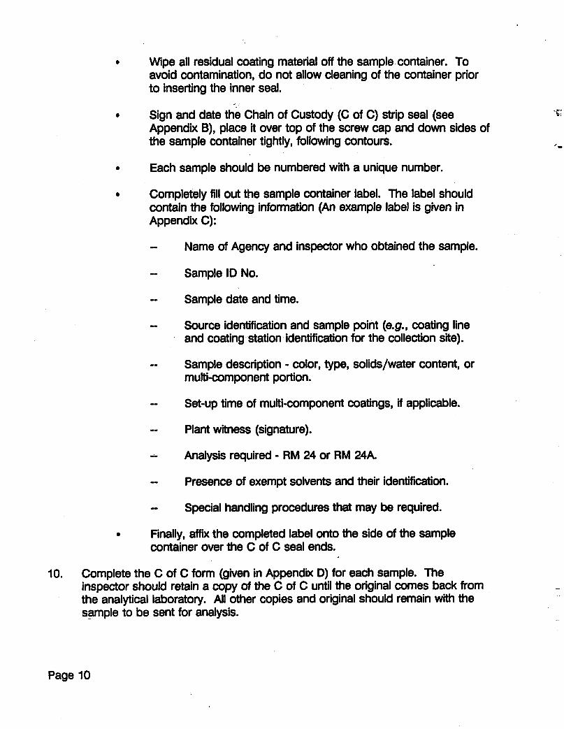
0 Wipe all residual coating material off the sample container. To avoid contamination, do not allow cleaning of the container prior to inserting the inner seal.
Sign and date the Chain of Custody (C of C) strip seal (see Appendix B), place it over top of the screw cap and down sides of the sample container tightly, following contours.
0
0 Each sample should be numbered with a unique number.
0 Completely fill out the sample container label. The label should contain the following information (An example label is given in Appendix C):
-- -- Sample ID No.
Name of Agency and inspector who obtained the sample.
- Sample date and time.
- Source identification and sample point (e.g., coating line and coating station identification for the collection site).
Sample description - color, type, solids/water content, or multi-component portion.
--
- Set-up time of multi-component coatings, if applicable.
- Plant witness (signature).
- Analysis required - RM 24 or RM 24A.
- Presence of exempt solvents and their identification.
- Special handling procedures that may be required.
0 Finally, affix the completed label onto the side of the sample container over the C of C seal ends.
I O . Complete the C of C form (given in Appendix D) for each sample. The inspector should retain a copy of the C of C until the original comes back from the analytical laboratory. All other copies and original should remain with the sample to be sent for analysis.
Page 10
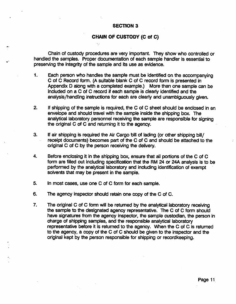
*-
SECTION 3
CHAIN OF CUSTODY (C of C)
Chain of custody procedures are very important. They show who controlled or handled the samples. Proper documentation of each sample handler is essential to preserving the integrity of the sample and its use as evidence.
1.
2.
3.
4.
5.
6.
7.
Each person who handles the sample must be identified on the accompanying C of C Record form. (A suitable blank C of C record form is presented in Appendix 0 along with a completed example.) More than one sample can be included on a C of C record if each sample is clearly identified and the analysis/handling instructions for each are clearly and unambiguously given.
If shipping of the sample is required, the C of C sheet should be enclosed in an envelope and should travel with the sample inside the shipping box. The analytical laboratory personnel receiving the sample are responsible for signing the original C of C and returning it to the agency.
If air shipping is required the Air Cargo bill of lading (or other shipping bill/ receipt documents) becomes part of the C of C and should be attached to the original C of C by the person receiving the delivery.
Before enclosing it in the shipping box, ensure that all portions of the C of C form are filled out including specification that the RM 24 or 24A analysis is to be performed by the analytical laboratory and including identification of exempt solvents that may be present in the sample.
In most cases, use one C of C form for each sample.
The agency inspector should retain one copy of the C of C.
The original C of C form will be returned by the analytical laboratory receiving the sample to the designated agency representative. The C of C form should have signatures from the agency inspector, the sample custodian, the person in charge of shipping samples, and the responsible analytical laboratory representative before it is returned to the agency. When the C of C is returned to the agency, a copy of the C of C should be given to the inspector and the original kept by the person responsible for shipping or recordkeeping.
'-
Page 11
Page 12
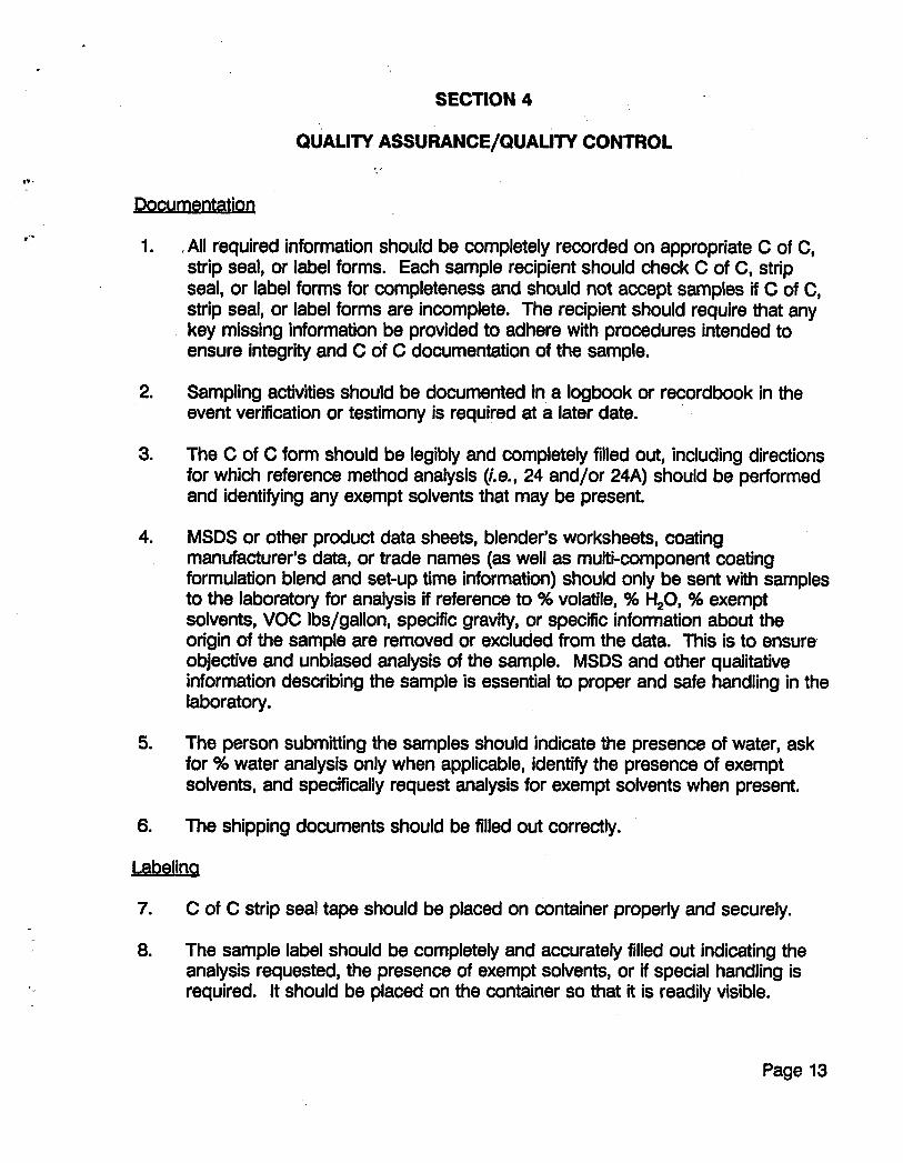
SECTION 4
QUALITY ASSURANCE/QUALITY CONTROL
Pocumentation
1.
2.
3.
4.
5.
6.
,All required information should be completely recorded on appropriate C of C, strip seal, or label forms. Each sample recipient should check C of C, strip seal, or label forms for completeness and should not accept samples if C of C, strip seal, or label forms are incomplete. The recipient should require that any key missing information be provided to adhere with procedures intended to ensure integrii and C of C documentation of the sample.
Sampling activities should be documented in a logbook or recordbook in the event verification or testimony is required at a later date.
The C of C form should be legibly and completely filled out, including directions for which reference method analysis (Le., 24 and/or 24A) should be performed and identifying any exempt solvents that may be present.
MSDS or other product data sheets, blender’s worksheets, coating manufacturer’s data, or trade names (as well as multi-component coating formulation blend and set-up time information) should only be sent with samples to the laboratory for analysis if reference to % volatile, % H,O, % exempt solvents, VOC Ibs/gallon, specific gravity, or specific information about the origin of the sample are removed or excluded from the data. This is to ensure objective and unbiased analysis of the sample. MSDS and other qualitative information describing the sample is essential to proper and safe handling in the laboratory.
The person submitting the samples should indicate the presence of water, ask for % water analysis only when applicable, identify the presence of exempt solvents, and specifically request analysis for exempt solvents when present.
The shipping documents should be filled out correctly.
jsbeling
7.
8.
C of C strip seal tape should be placed on container properly and securely.
The sample label should be completely and accurately filled out indicating the analysis requested, the presence of exempt solvents, or if special handling is required. It should be placed on the container so that it is readily visible.
Page 13
9. When the sample contains an exempt solvent or a multi-component coating to be specially blended (mixed) by the analytical laboratory, a special tag should be completed and affixed to the sample (such as a 2%” by 4%” label tied to the sample can with a string) to notify the lab that the sample requires special handling or analysis.
IO. The shipping labels should be filled out correctly.
Sample lntearity
11. The sample container should be filled to overflowing prior to placing inner seal in container. A partially filled container indicates potential VOC loss or some other problem with the sample. A repeat sample is required.
To avoid potential sample contamination, the outside of the sample container should be wiped clean immediately after being sealed.
12.
13. If analytical laboratory personnel receive samples stored in inappropriate containers or if there are any other problems associated with sample integrity or documentation, they should immediately report these problems to agency personnel.
Page 14
SECTION 5
HANDLING .
Simple common sense should be used in handling collected samples to ensure sample integrity and custody control.
1. Maintain samples at room temperature, preferably at 7OoF but within the range of 40 to IOOOF. Do not store sample containers in hot areas such as a closed vehicle. Keep out of direct sunlight and keep from freezing.
2. After properly sealing the sample container, the sample should be secured in a safe place and maintained at a temperature that is compatible with the coating. The packing requirements of individual samples depend on the coating's physical and chemical properties. Coatings with relatively high vapor pressures (Le., those containing volatile solvents with boiling points below 100°F) should be packed in ice to keep them within the temperature range of 40 to 100°F. The inspector or person responsible for samples should use ice packs or other more durable means to keep samples cool if they must be held for extended times or may be exposed to extreme heat. Use special insulated containers to avoid volatilization, particularly in warm climates. The temperature sensitivity of the coating should also be checked to determine if packing in ice may have a detrimental effect on the sample by causing solidification, separation, or any other change in its properties. Other samples which are not volatile at low temperatures, such as those with boiling points higher than 100"F, may be packed and shipped at room temperature. The MSDS on coatings and dilution solvents supply sufficient information to determine the coating properties.
3. When packaging samples for shipment, use bubble packing or crumpled paper to line the bottom of the box. The box should be firm, adhering to specifications given by the US Department of Transportation - DOT 12-B.8*9 Place the sample container in the box with the top up. Pack additional bubble pack or paper around the container so that the entire inner space of the box is sufficiently filled, to keep the sample container in the upright position and to prevent the container from shifting while in transit.
4. Enclose both the completed C of C form and a stamped envelope addressed to the agency for return of the C of C form in a larger envelope addressed to the analytical laboratory to which the sample is being sent. Place it on top of the packing over the sample containers and close the box.
5. Seal the box with strapping tape.
Page 15
6. Paint and coating samples are considered hazardous material and should be shipped as a restricted article by Federal Express or another suitable carrier that can provide special handling. Label the outside of the box with sender/ receiver addresses. If used, insert the completed air bill/cargo bill in its proper pocket and seal.
7. For all mail, courier, or special delivery service shipping, the box should have the following designations:
'C
*w
0 On top of box: "TOP - THIS SIDE UP." 0 On all sides of box: arrows pointing up. 0 On bottom of box: "OTHER END UP." 0 On one side of box: "Flammable liquid UN No. 1263." 0 On opposite sides of box: "Danger" and "Flammable Liquid" labels. 0 On fourth side of box: Name and address of the person shipping
the samples. 0 On top of box: Shipping destination name and address along with
any additional labels required by shipping company, such as the restricted article form used by Federal Express.
0. DO NOT HO LD. Ideally, a sample should be delivered to the laboratory for analysis on the same day it is obtained. If a sample must be stored overnight, it should be kept in a secure place, away from extreme temperatures and away from danger of breakage, leakage, or tampering, preferably in a locked storage cabinet. Maintain a sample log for those samples stored overnight. The log should contain the following information:
0 Sample number. 0 Facility name and location.
0
0
0 Date/time sample obtained. Date sample was placed into locked storage cabinet. Date when sample was mailed to the laboratory for analysis.
NOTE: SAMPLES SHOULD NOT BE MAILED ON A FRIDAY BECAUSE THEY WILL NOT BE DELIVERED UNTIL MONDAY. THIS MAY INTRODUCE SOME SUBSEQUENT QUESTION ABOUT ADEQUATE CHAIN OF CUSTODY OR SAMPLE INTEGRITY.
Page 16
6. REFERENCES
1. Standard Practice for Sampling Liquid Paints and Related Pigmented Coatings, ASTM D3925-81 (Re-approved 1985). 1990 Annual Book of ASTM Standards, Volume 6.01 , Philadelphia, PA, 1990.
2. Standard Methods for Sampling of Testing Shellac Varnish, ASTM D1650-76, 1990 Annual Book of ASTM Standards, Volume 6.02, Philadelphia, PA, 1990.
3. Standard Practice for Manual Sampling of Petroleum Products, ASTM Method D4057-88, Volume 5.01 , Philadelphia, PA, 1990.
4. Standard Practice for Sampling Industrial Chemicals, ASTM Method E300-86, Volume 6.03, Philadelphia, PA, 1990
5.
6.
7.
0.
9.
10.
11.
12.
1 3:
EPA-340/1-88-003, Recordkeeping Guidance Document for Surface Coating Operations and the Graphics Arts Industry, U.S. EPA, Stationary Source Compliance Division, Washington, DC, May 1989.
"Information on Sample Taking and Sample Transport/ Field Sampling Guidelines," (Draft), Bay Area Quality Management District, San Francisco, California, July 1990.
Code of Federal Regulations, Tile 29, Part 1910, Occupational Safety and Health Standards, Department of Labor, July 1, 1989.
Dangerous Goods Regulations, 31 Edition, International Air Transport Association, Montreal, Quebec, Canada, 1990.
b
Code of Federal Regulations, Tile 49, Part 178, Subpart F- Specifications for Fiberboard Boxes, Specification 12-B, Department of Transportation (49 CFR 178.205), October 1, 1989. '
EPA-450/3-84-019, Procedures for Certifying Quantity of Volatile Organic Compounds Emitted by Paint, Ink, and Other Coatings, U.S. EPA, OAQPS, ESED, Research Triangle Park, NC, December 1984.
"EPA Region II Sampling Procedure," (Draft), New York, New York, June 1990.
"EPA Region I: VOC Sampling/Analysis," (Draft), McCusker, Boston, Massachusetts, June 7, 1990.
"Sampling Techniques & Test Methods," (Draft), California Air Resources Board, Sacramento, California, July 30, 1990.
Page 17
14. Federal Test Method Standard No. 141c, Paint, Varnish, Lacquer, and Related Materials; Methods of Inspection, Sampling, and Testing. General Services Administration, January 24, 1986.
EPA-600/9-76-005, Quality Assurance Handbook for Air Pollution Measurement Systems: Volume 1. Principles. U.S. EPA, EMSL, Research Triangle Park, NC, December 1984.
15.
16. EPA-600/4-77-027b, Quality Assurance Handbook for Air Pollution Measurement Systems: Volume 111. Stationary Source Specific Methods. U.S. EPA, EMSL, Research Triangle Park, NC, November 1976.
bcr
Note: References 10 through 16 were not directly cited in the Sampling SOP for RM 24/24A but the methods outlined in those references were generally incorporated. They are considered generally relevant and useful sources for sampling information.
Page 18

J
APPENDIX A COATING DATA SHEET
Page 19
Page 20
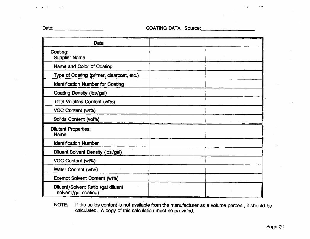
Date: COATING DATA Source:
Data
Coating: Supplier Name
Name and Color of Coating
Type of Coating (primer, clearcoat, etc.)
Identification Number for Coating
Coating Density (Ibs/gal)
NOTE: If the solids content is not available from the manufacturer as a volume percent, it should be calculated. A copy of this calculation must be provided.
Page 21
Page 22
APPENDIX B r
CHAIN OF CUSTODY (C of C) STRIP SEAL
Page 23
Page 24
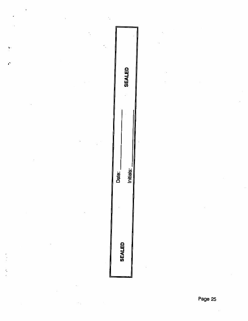
7 -
Page 25

Y
Page 26

APPENDIX C SAMPLE CONTAINER LABEL
Page 27

Page 28
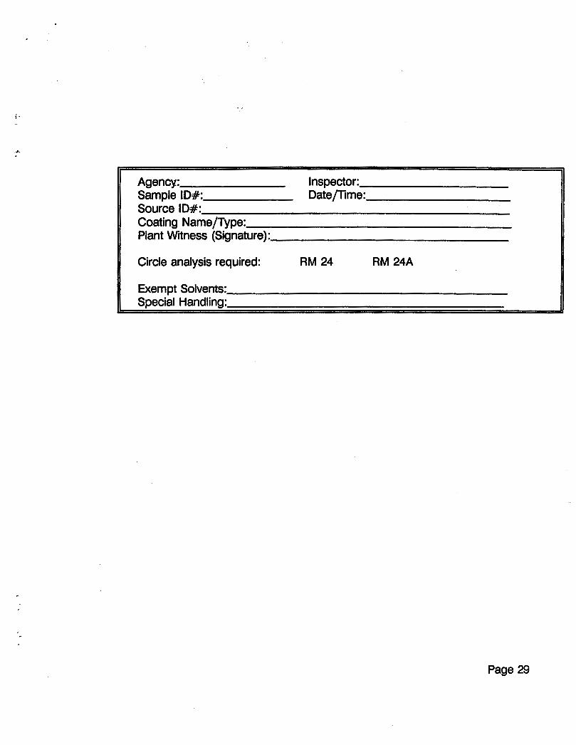
h
Agency: Inspector: Sample ID#: Datepime: Source ID#: Coating Namepype: Plant Witness (Signature):
Circle analysis required: RM 24 RM 24A
Page 29

1 .
Page 30
*.
APPENDIX D CHAIN OF CUSTODY FORM
L
Page 31

Page 32
I.
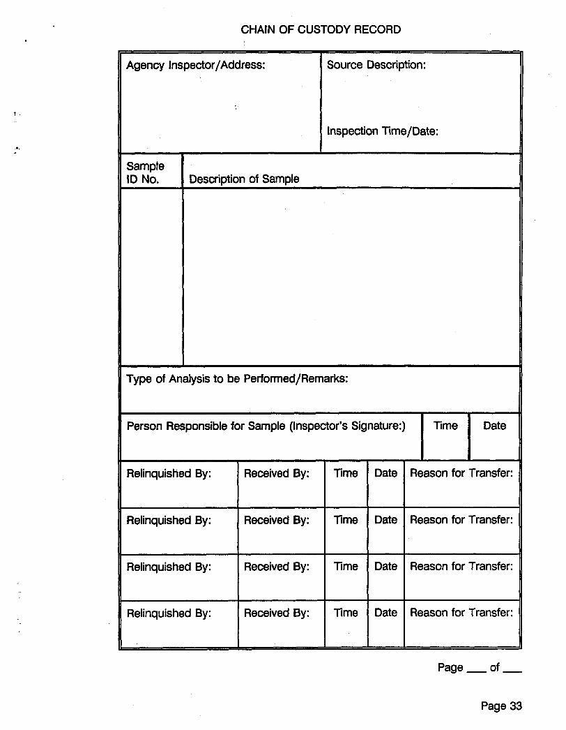
CHAIN OF CUSTODY RECORD
Agency Inspector/Address:
t .
Source Description:
Inspection Time/Date: r..
Sample ID No. Description of Sample
Person Responsible for Sample (Inspector's Signature:) Time Date
I'
Relinquished By:
Relinquished By:
Received By: Time Date
Received By: Time Date
11 Relinquished By: 1 Received By: 1 Time I Date
Relinquished By:
Reason for Transfer:
Received By: Time Date
Reason for Transfer:
Reason for Transfer:
Reason for Transfer:
Page - of -
Page 33

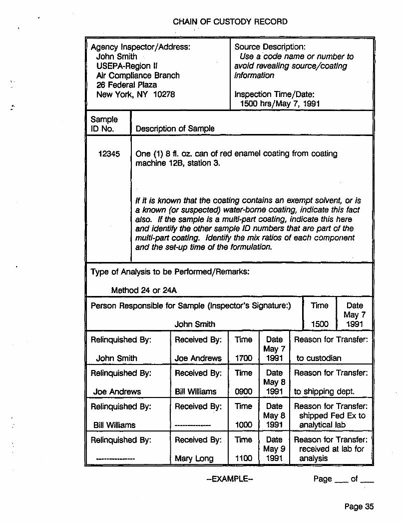
CHAIN OF CUSTODY RECORD
Agency Inspector/Address: John Smith USEPA-Region II Air Compliance Branch 26 Federal Plaza New York, NY 10278
\ '
Source Description:
avoid revealing source/coating information
Inspection Time/Date:
Use a code name or number to
1500 hrs/May 7, 1991
Person Responsible for Sample (Inspector's Signature:)
Sample ID No.
Time Date May 7
12345
Relinquished By:
John Smith
Description of Sample
Received By: Time
Joe Andrews 1700
One (1) 8 fl. 02. can of red enamel coating from coating machine 12B, station 3.
Date May 7 1991
Date May 8 1991
Date May 8 1991
If it is known that the coating contains an exempt solvent, or is a known (or suspected) water-borne coating, indicate this fact also. If the sample is a multi-part coating, indicate this here and identify the other sample ID numbers that are part of the multi-part coating. Identi@ the mix ratios of each component and the set-up time of the formulation.
Reason for Transfer:
to custodian
Reason for Transfer:
to shipping dept.
Reason for Transfer: shipped Fed Ex to analytical lab
Type of Analysis to be Performed/Remarks:
Relinquished By:
Joe Andrews
Received By: Time
Bill Williams 0900
John Smith
~ ~~
Relinquished By:
Bill Williams
Relinquished By:
---------c----
I 1500 1 I991
Received By: Time
loo0
Received By: Time
--------------
Mary Long 1 loo
Date May 9 1991
Reason for Transfer: received at lab for analysis
--EXAMPLE-- Page - of -
Page 35

.Y
Page 36
h
APPENDIX E DOT SPECIFICATION 12-B
FOR FIBERBOARD BOXES AS SHIPPING CONTAINERS
Page 37
Page 38
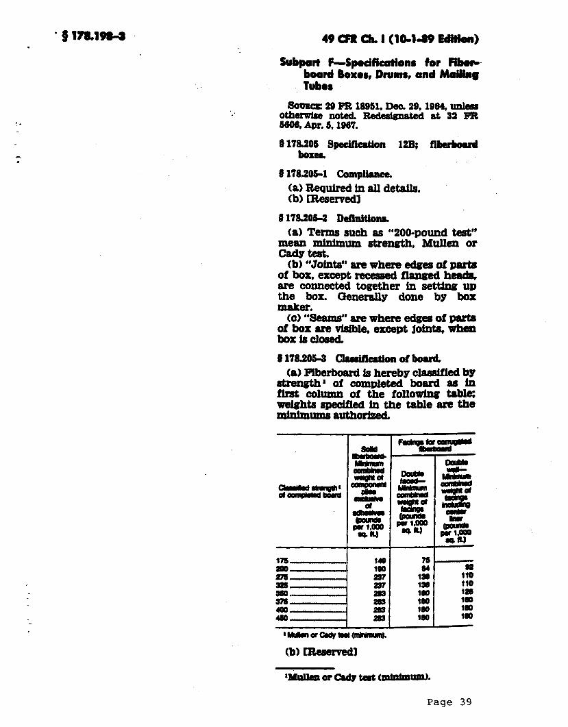
Subpart F-Spodktions for Ir?b.rc. board Bowos, Drums, ond Moiling Tub08
SO- 29 Pa 18951, Dec. 29,1964. Wm otherwi6e noted. wu&llated at 91 FR 5606. Avr. 5,1967,
8178.205 Bpceification 12B; IiberJmrd borer.
8 178206-1 Compkce. (a) Required in all detsfls. (b) [Reservedl
9 178.206-2 Deflnitiom. (a) Terms such 88 d b 2 0 0 - p ~ ~ d test’’
mean minimum strength, Mullen or csdgtesf, (b) “Joints” are where edges of parts
of box, except receased flanged head8, are connected together ln setfino up the box. QeneraJly done by box maker.
tc) “Seams” are whem edges of Dufrr of box are visible, ercept jotnta when box is clo8ed
9 178.2064 ChMcation of boud (8) Flberbaard is hereby classfifed by
-* of completed board aa in fhst column of the following table m h t s spedfied fa the table am the mhlmums authorized
I.
149 190 a7 237 283 aa ma 283
I 75 e4 1 s 130 lbb 100 180 180
‘Mullen or Cadv tad mht“iatm).
Page 39
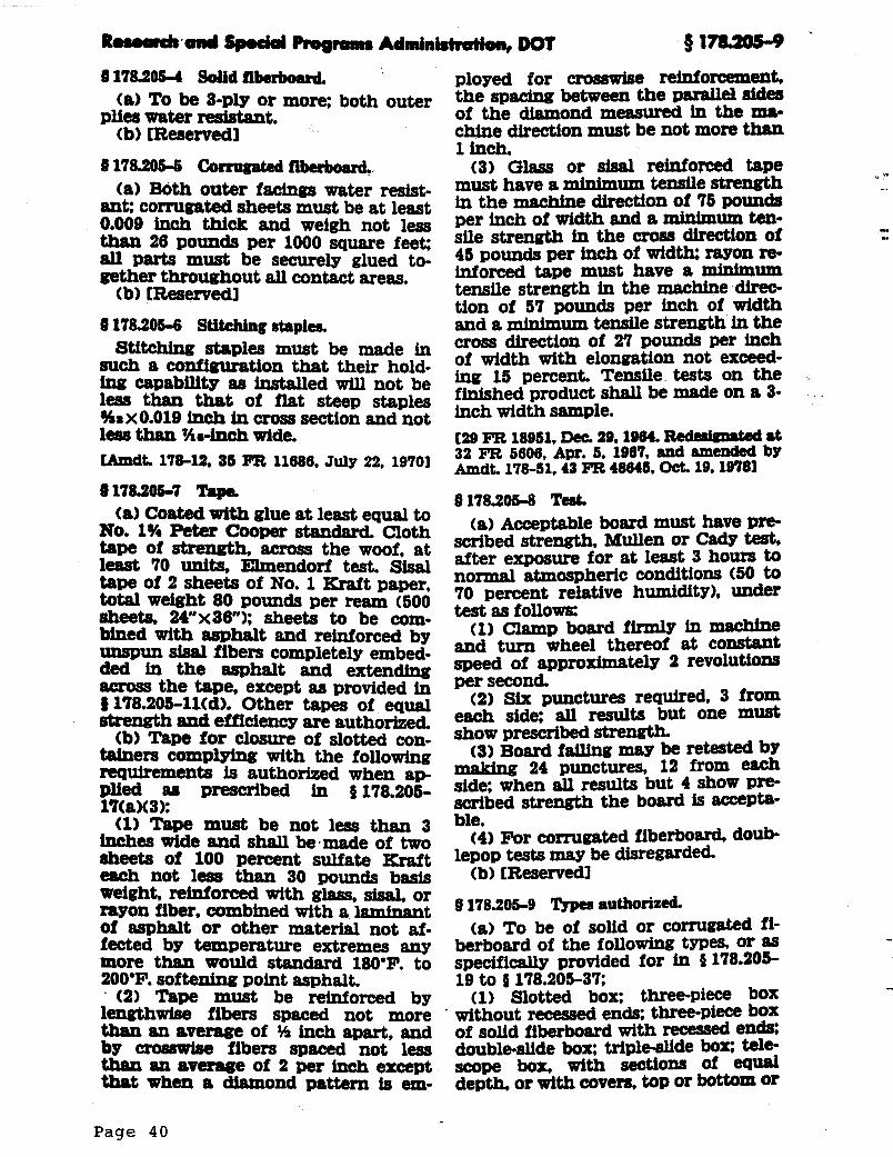
9178.2064 Solidfibuboard. (a) To be 8-ply or more; both outer
plies water reswlant. (b) [Reservedl
ffl78.2OS-6 Comugatedfibuboard. (a) Both outer f- water resist-
ane corrugafad sheets must be at least 0.009 inch thick and weigh not less thlln 26 pounds per 1000 square feet: all parts must be securely glued to- gether throughout all contact areas.
(b) [Reservedl 9 178.2064 Stitching stapiea
Stitching staples must be made in such a configuration that their hold- ing capability 88 installed will not be
%sX0.01@ inch hl Cross SecfiOn and not less than h-inch wide. CAmdt. 17842, 85 FR 11686, July 22, 19701
0178.2067 T.pc (a) Coated with glue at least equal to
No. 1% Peter Cooper standard. Cloth tape of strength, across the woof, at least 70 units, Elmendorf test. Sisal tape of 2 sheets of No. 1 Kra,ft paper, total weight 80 pounds per ream (500 sheets, 24"x36"); sheets to be com- bined with asphalt and reinforced by " p u n sisal fibers completely embed- ded in the asphalt and extending across the tape, except 85 provided in 8 178.20&11(d). Other tapes of equal atmmgth and ef'ficiency are authorized.
(b) Tape for closure of slotted con- tainera complying with the following requireme!nts ls authorized when ap-
lltaI(3 1: (1) Tape must be not less than 3
inches wide and shall be-made of two aheets of 100 percent sulfate Kraft each not less than 30 pounds basis weight, reinforced with glass, sisal, or rayon fiber, combined with a 1 a " n t of asphalt or other material not a$- fected by temperature extremes any more than would standami 180'F. to
' (2) Tape must be reinforced bv
less than that of flat steep staples
Plied 88 Prescribed in 0178.205-
200'F. softening point asphalt.
ployed for crosswhe rebforcement. the spacing between the paraUe4 sides of the diamond measured in the IP& chine direction must be not more than 1 inch,
(3) Glass or sisal reinfomed tape must have a minimum tensile strength in the machine direction of 75 pounds per inch of width and a minimum ten- sile strength in the cross direction of 45 pounds per inch of w i d a rayon re- inforced tape must have a mintmum tensile strength in the machine direc- tion of 57 pounds per inch of width and a mintmum tensile strength in the cross direction of 27 pounds per inch of width with elongation not exceed- ing 15 percent. Tensile tests on the finished product shall be made on a 3- inch width sample.
32 FR 5606, Apr. 5, 1967, and amended by
ff178.2068 Teat. (a) Acceptable board must have xne-
scribed strength, Mullen or cad^ te9f, after exposure for at least 3 hours to normal atmospheric conditions (50 to 70 percent relative humtdity), under test 85 follows:
and turn wheel thereof at constant speed of approximately 2 revolutions per second.
(2) Six punctures required 3 from each side: all results but one must show prescribed
(3) Board fsiling may be retested by making 24 punctures, 12 from each side: when all results but 4 show p m scribed strength the board is -Ph- ble.
(4) For corrugated fiberboard daub- lepop tests may be disregarded
(b) [Reservedl 178.205-9 "ypw authorized. (a) To be of solid or corrugated fi-
berboard of the following types, or 85 specifically provided for in 9 178.205-
(1) Slotted box: three-piece box
129 FR 18951, b 39,196& Red- 8t
h d t . 178-51,43 PR 48645, Ocf. 19,19781
(1) clamp board finnly in mnehtne
19 to 9 178.205-37;
lensthwfse fibers spaced n o t - m o r i . without recessed ends: three-piece box than an av- of % inch apart, and of solid fiberboard with recessed ends; bY cro8" fibers spaced not less double-slidebox: tripledde box; tele- than anavemwe of 2 per inch except scope box, with sections of equal that When a diamond pattern is em- depth. or with covers, top or bottom O r
.- u
Page 4 0
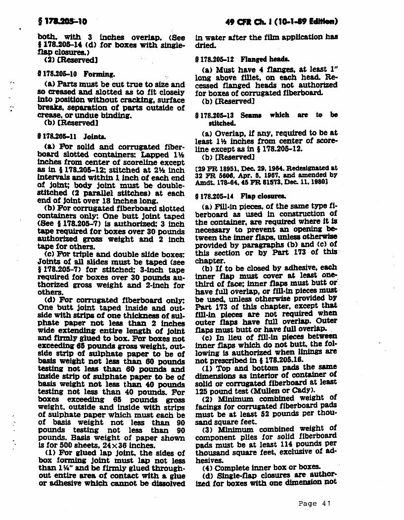
*.
9 1 ~ 1 0 49 011: clr. I (1011.80 -1 both, with 3 hches overlap. (See inwaterafterthe~~appli~tionhrrs 0 178.206-14 (d) for boxea with single dried. flap closures)
(2) [Reservedl Q 178.205-12 Flanged headr. $178.20&10 Forming.
(a) Parts must be cut true to size and so creased and slotted as to f i t closely into position without cracking, surface breaks, separation of parts outside of crew, or undue binding. (b) [Reservedl
Q 118.20611 Joints. (a) For solid and corrugated fiber-
board slotted containers: hpped 1% inches from center of scoreline except as in (t 178.205-113 stitched at 2% inch intervals and within 1 inch of each end of joint; body joint must be double- stitched (2 parallel stitches) at each end of joint over 18 inches long.
(b) For corrugated fiberboard slotted containers only: One butt joint taped (Sex? 0 178.205-7) is a u t h o m 3 inch tape required for boxes over 30 pounds authorized gross weight and 2 inch tape for others.
tc) For triple and double slide boxes: Joints of all slides must be taped (see 3 178.205-7) for stitched: 3-inch tape required for boxes over 30 pounds au- thorized gross weight and 2-inch for ofhers.
(d) For corrugated fiberboard only: One butt joint taped inside and out- side with strips of one thickness of sul- phate paper not less than 2 inches wide extending entire length of joint and firmly glued to box. For boxes not exceeding 65 pounds gross weight, out- side strip of sulphate paper to be of basis weight not less than 60 pounds testing not less than 60 pounds and h i d e strip of sulphate paper to be of basis weight not less than 40 pounds testing not less than 40 pounds. For boxes exceeding 65 pounds gross weight, outside and inside with strips of sulphate paper which must each be of basis weight not less than 90 pounds testing not less than 90 pounds. Basis weight of paper shown is for 500 sheets, 24 x 36 inches.
(1) For glued lap joint, the sides of box forming joint must lap not less than 1%" and be firmly glued through- out entire area of contact with a glue or adhesive whiqh cannot be dissolved
(a) Must have 4 flanges, at least 1'' long above fillet, on each head. Re- cessed flanged heads not authorized for boxes of corrugated fiberboard.
ff 178.205.13 Seama which are to be
(a) Overlap, if any, required to be at least 1% inches from center of score- line except as in 9 178.205-12.
(b) [Reservedl
(b) [Reservedl
stitched
C29 18951, Dee. 29, 196k Red-w 8t 32 FR 5606, Apr. 5, 1967, and amended by Amdt. 178-64,45 FR 81573, Dec. 11,l98Ol
ff 178.205-14 Flap cloauru. (a) F%in pieces, of the same type fi-
berboard as used in construction of the container, are required where if is necessary to prevent an openinn be- tween the inner flaps, unless otherwise provided by paragraphs (b) and tc) of this section or by Part 173 of this chapter. (b) If to be closed by adhesive, each
inner flap must cover at least one third of face: inner flaps must butt or have full overlap, or fill-in pieces must be used, unless otherwise protrided by Part 173 of this chapter, except that fill-in pieces are not required when outer flaps have full overlap. Outer flaps must butt or have full overlap.
tc) In lieu of fill-in piecea between inner flaps which do not butt, the fob lowing is authorized when lfntnns are not prescribed in 4 178.205.16.
(1) Top and bottom pads the same dimensions as interior of container of solid or corrugated fiberboard at least 125 pound test (Mullen or CadY).
(2) Mini" combined weight of facings for corrugated fiberboard pads must be at least 52 pounds per thou- sand square feet.
(3) lKinimum combined weight of component plies for solid fiberboard pads must be at least 114 pounds Per thousand square feet, exclusive of ad- hesives.
(4) Complete inner box or boxes. (d) Singleflap closures are 8UthOr-
ized for boxea wi th one dimension not
Page 4 1
R...onh a d Sp.dcll Pmgromr Administ", DOT ~17S.ZO5-17
over 2'7 each flap must be scored and form one of the small faces of the box and lap at least 5" on one of the larg- est faces. 129 FR 18951, Dec. 29,1964, as amended by Order 67,30 FR 7425. June 5,196S. Redesig- nafed at 32 FR 5606, Apr. 5,19671
~17&20&16 Lininga (when prescribed by
(a) Of l-piece to extend around 4 faces with joint at center of 1 face and
each end (comers may be mitered) to
Q 178.206-16).
With 4 8t 1%" long, On
3 thtchnessea throulthout face. For boxes with 1 dimension not over 3". one of the widest flsnges p18jr be lengthened to cover entire face and lap 6" on the adjoininn face and the other flangea and the pads m y then be omitted.
c29 FR 18951, Dec. 29, 1964, as amended by Order 67,30 FR 7435, June 5,1965. Red-- nated at 32 FR S606, Apr. 5,19671
Q178.205-16 Authorized WM weight and
(b) [Reservedl
bend over the other-2 faces; also 2 (a) The authorlzed gross weight P8dS to cover the other 2 faces. Pads (when packed) and the parts rmutred
be omiffed if closing flaps afford are as follows:
(b) Triple slide boxes authorized for gross weights 88 follows: Of board at leasf 17b-pound test for 40 pounds; of board at least 200-pound test for 65 pounds. 129 FR 18QS1, Dec. 29,1964. Redesignated at 32 FR S606. Apr. 5, 196?, and by a d t . 17&8b,51 FR 5976. Feb. 18,19881
1 178.20617 Clming for rhipment. (a) Slofted container, by coating
with adhesive the entire contact sur- faces of closing flaps and fill-in pieces where required or as prescribed in paragraph (a) (11, (21, or (3) of this section9 (1) By stitching with staples as pre-
scribed by 9 178.205-6 at 2%-inch inter- vals along all seams tone 5-inch space allowed when necessary to permit use of stitching device): or with staples made of flat wire of hardness not less than equivalent of Rockwell B90, and
not less than 0.037 inch thick aud not less than 0.074 inch wide, with not less than 1% inch crown. may be spaced not more than 5 inches apart. Such staples may be used across center seam where outside flaps meet in lieu of on both sides of center seam but need only be used where outside flaps overby inner flaps: or staples d e of arcuate wire of hardness not legs than equivalent of Rockwell B90, and not less than 0.027 inch thick and not less than 0.095 inch wide. with not less than 1 inch crown, may be sp8ced not more than 5 inches apart. Such stitch- es when spaced not more than 2% inches apart may be used across center seam where outside flaps meet in lieu of on both sides of center seam but need only be used where outside flaps overlay inner flaps.
(2) For fiberboard box- C O ~ t a i n h e not more than 1 inside metal can not
. *I ...
$11 u
Page 4 2
r * I
8 178.20S-17
exceeding 1 gallon no- capacity, and as otherwise authorized by Part 173 of this chapter, by application of 2 strips of pressure-sensitive tape not less than % inch in width, 1 strip to be placed approximately equal d@tance over the seam of abutting outer flaps, the other at a right angle to the first and spaced approximately equal dis- tance on the closure face: strips must be of sufficient length to extend not less than 1 inch beyond score lines on side and end panels; Tape shall have a minimum tensile strength of 160 pounds per inch of width; minimum adhesion value of 18 ounces per inch of width, and minimum elongation of 12 percent at break, or having a mM- mum longitudinal tensile strength of not less than 240 pounds per inch of widfh: minimum adhesion value of 18 ounces per inch of width and a mini- mum elongation of 3 percent at break.
(3) For slotted containers only, rein- forced tape complying with the re- quirements of 0 178.205-Wb) is author- ized for application over the center seam only. Tape must extend over the ends of box not less than 2% inches.
(4) All closing flaps m a y be finnly glued with a hot-melt adhesive of 100 percent solid content of thermoplastic material which will maintain bond at temperature ranging from 20' F. below zero to 165' F. above zero. Adhesive must be applied in not less than eight stripes (except as specified below) on each inner flap, each stripe having a minimum width of inch after com- pression. Stripes may not be more than 1% inches apart and not less than four stripes must be applied on each side of center seam on each inner flap for full length of flap overlap area with one stripe not more than %- inch from each side of center seam. If less than eight such stripes are applied on each inner flap, adhesive must cover and securely bond not less than 25 percent of flap contact mea with bonded areas extending to within %- inch or less of center seam.
(5) For regular slotted containers, pressure-sensitive tape is authorized for application over the center seams only and extending not less than two inches over the ends of the box. Tape must be not less than 2 inches wide and have a plastic film backing of pol-
49 CFR Ch. l (10-1-89 Edition)
yester, polspropylem, or equivalent material. Tape must have a minimum tensile strength of 46 pounds per inch of width in the machine direction and not less than 55 pounds per inch of width in the cross direction and may not be affected by temperature ex- tremes normally encountered during transportation. Boxes closed by m e w of this pressure-sensitive tape must be capable of passing performance tests prescribed in 0 178.210-10.
(b) Double slide boxes or triple slide boxes, by coating the inner slides with adhesive, or by closing with rebforced tape capable of withstanding test pre- scribed by paragraph (b)(l) of this sec- tion: for single-flap closures as author- ized for boxes with one dimension not over 2 inches, the flaps must be fas- tened to the body with adhesive.
(1) Boxes selected at random, con- taining dummy contents similar to that to be shipped and packed to au- thorized gross weight, closed with re- inforced tape across the ends and onto opposite side panels at least 2 fnches, must be capable of Withstandine a drop on each end from a height of 4 feet onto solid concrete without clo- sure failure.
(c) Eiberboard boxes with covers ex- tending over sides but not to bottom, covers resting on walls of box, or tele- scope boxes of equal depth sectfon, covers extending to bottom, must be secured by one of the foUo-g meth- ods:
(1) By not less than three metal straps, one lengthwise and others at right angles thereto.
(2) When cover extends not 1- than 3 inches over the walls of the box, by coating with adhesive the entire contact area of the cover.
(3) Telescope boxes bavfng eQw depth sections may be closed by aPPli- cation of reinforced water activated tape or pressure sensitive tape under conditions and for commodities as pre- scribed in Part 173 of this chapter.
(d) When metal straps are specified, boxes must be strapped with the re- quired number, size at least % inch x 0.015 inch.
Amdt. 17841.42 FR 28135. June 2,19771
C29 FR 180Sl. Dec. 20,1964. RedesiOnated at 32 FR 5606, Apr. 5. 1967, and amended by
Page 4 3
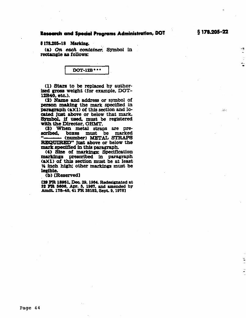
R.woroh and Sp.dal Programs Administration, DOT
917820b18 Marking.
“ g l e as follows: (a) On each contcrfw. Symbol in
(1) Stars to be replaced by author- Ized gross weight (for example, DOT- 12B40, e&).
(2) Name and address or symbol of person making the mark specified in Paratgraph taMl) of this section and lo- cated just above or below that msrk, Symbol. if used must be registered with the Director, OHhsr.
(8) When metal straps are pre- sdbed, boxes must be marked “- (number) METAL STRAPS RSQ-’ just above or below the m8rkspedffed hl this paragraph.
(4) Size of markings: Specification prescribed in pammph
taX1) of this section must be at least 34 inch hig& other markings must be legible. (b) [Reservedl
C28 FIB l8OSl. Dec. 29,1964. Redesienated at 32 Pa 5608, Apr. 5, 1967, and amended by AmdL 17840.41 FR 38182. Sat. 9,19761
Page 4 4
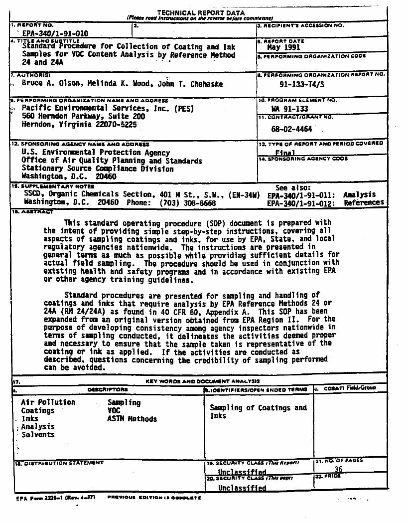
' EPA-340/1-91-010 A. TI E A N O S U TITLE
lkandard brocedure for Collection o f Coating and Ink 24 and 24A * * .
Samples for VOC Content Analysis by Reference Hethod
3. RECIPIENT'S ACCESSION NO.
S. REPORT OATS Hay 1991
6. CCIIPORMINO OROANIZATION COOE
This standard operating procedure (SOP) document is prepared with the intent of providing simple step-by-step instructions, covering all aspects of sampling coatings and inks, for use by EPA, State, and local regulatory agencies nationwide. The instructions are presented in general terms as much as possible while providing sufficient details for actual field sampling. The procedure should be used in conjunction with exlsting health and safety programs and in accordance with existing EPA or other agency training guide1 ines.
L 8. PERCORMINO OROANlZArlON REPORT NO 7. AUTTWORtSI
\., Bruce A. Olson, Melinda K. Wood, John T. Chehaske 91-1 33-T4/S
9. PERFORMING OAOANIZATION NAMO A N 0 AODRtSS
' 560 Hemdon Parkway, Suite 200 11. CONTRACTJOR ANT NO.
10. PROGRAM hLEMENT NO.
Pacific Environmental Services, Inc. (PES) WA 91-133
60-02-4464 Herndon, Virginia 22070-5225
Standard procedures are presented for sampling and handling of coatings and inks that require analysis by EPA Reference Methods 24 Or 24A (m 24/24A) as found in 40 CFR 60, Appendix A. This SOP has been expanded from an original version obtained from EPA Region 11. For the purpose of developing consistency among agency inspectors nationwide in terms of sampling conducted, it delineates the activities deemed Proper and necessary to ensure that the sample taken i s representative of the coating or ink as applied. If the activities are conducted as described, questions concerning the credi bil i ty of sampl ing performed can be avoided.
12. SPONSOFIINO AQBNCY NAY. AN0 AOORESS
U.S. Environmental Protectton Agency Stationary Source Compliance Division Washington, D.C. 20460
Office o f Air Quality Planning and Standards
13. TYPE OF RECORT AN0 PER100 COVhngO
F-1 14. SPONSORING AGINCY Coos

Appendix E
Accredited Laboratories
Showing only laboratories accredited for Clean Air Act (CCA) testing
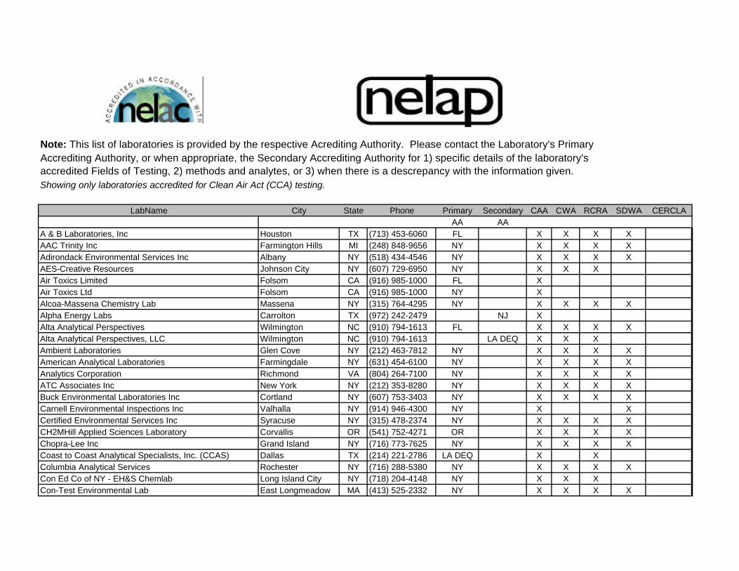
Showing only laboratories accredited for Clean Air Act (CCA) testing.
LabName City State Phone Primary Secondary CAA CWA RCRA SDWA CERCLAAA AA
A & B Laboratories, Inc Houston TX (713) 453-6060 FL X X X XAAC Trinity Inc Farmington Hills MI (248) 848-9656 NY X X X XAdirondack Environmental Services Inc Albany NY (518) 434-4546 NY X X X XAES-Creative Resources Johnson City NY (607) 729-6950 NY X X XAir Toxics Limited Folsom CA (916) 985-1000 FL XAir Toxics Ltd Folsom CA (916) 985-1000 NY XAlcoa-Massena Chemistry Lab Massena NY (315) 764-4295 NY X X X XAlpha Energy Labs Carrolton TX (972) 242-2479 NJ XAlta Analytical Perspectives Wilmington NC (910) 794-1613 FL X X X XAlta Analytical Perspectives, LLC Wilmington NC (910) 794-1613 LA DEQ X X XAmbient Laboratories Glen Cove NY (212) 463-7812 NY X X X XAmerican Analytical Laboratories Farmingdale NY (631) 454-6100 NY X X X XAnalytics Corporation Richmond VA (804) 264-7100 NY X X X XATC Associates Inc New York NY (212) 353-8280 NY X X X XBuck Environmental Laboratories Inc Cortland NY (607) 753-3403 NY X X X XCarnell Environmental Inspections Inc Valhalla NY (914) 946-4300 NY X XCertified Environmental Services Inc Syracuse NY (315) 478-2374 NY X X X XCH2MHill Applied Sciences Laboratory Corvallis OR (541) 752-4271 OR X X X XChopra-Lee Inc Grand Island NY (716) 773-7625 NY X X X XCoast to Coast Analytical Specialists, Inc. (CCAS) Dallas TX (214) 221-2786 LA DEQ X XColumbia Analytical Services Rochester NY (716) 288-5380 NY X X X XCon Ed Co of NY - EH&S Chemlab Long Island City NY (718) 204-4148 NY X X XCon-Test Environmental Lab East Longmeadow MA (413) 525-2332 NY X X X X
Note: This list of laboratories is provided by the respective Acrediting Authority. Please contact the Laboratory's Primary Accrediting Authority, or when appropriate, the Secondary Accrediting Authority for 1) specific details of the laboratory's accredited Fields of Testing, 2) methods and analytes, or 3) when there is a descrepancy with the information given.
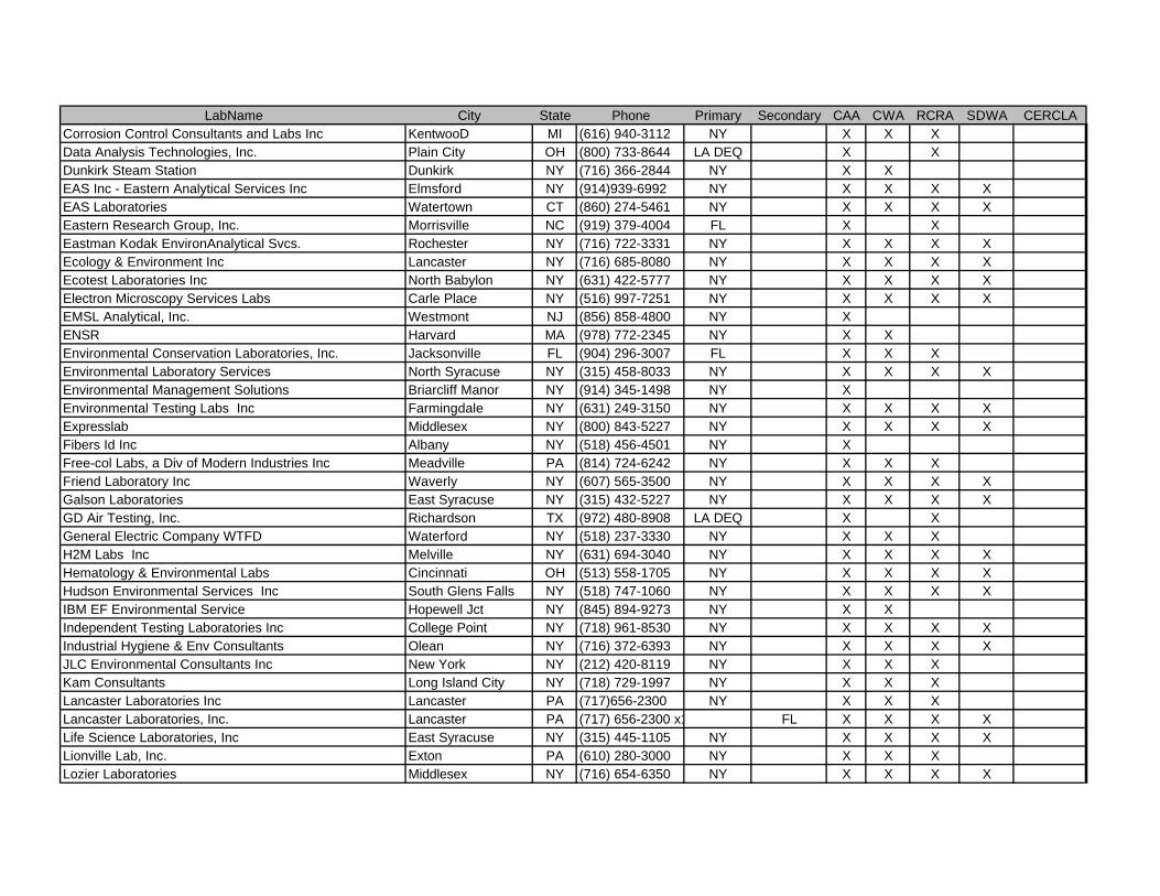
LabName City State Phone Primary Secondary CAA CWA RCRA SDWA CERCLACorrosion Control Consultants and Labs Inc KentwooD MI (616) 940-3112 NY X X XData Analysis Technologies, Inc. Plain City OH (800) 733-8644 LA DEQ X XDunkirk Steam Station Dunkirk NY (716) 366-2844 NY X XEAS Inc - Eastern Analytical Services Inc Elmsford NY (914)939-6992 NY X X X XEAS Laboratories Watertown CT (860) 274-5461 NY X X X XEastern Research Group, Inc. Morrisville NC (919) 379-4004 FL X XEastman Kodak EnvironAnalytical Svcs. Rochester NY (716) 722-3331 NY X X X XEcology & Environment Inc Lancaster NY (716) 685-8080 NY X X X XEcotest Laboratories Inc North Babylon NY (631) 422-5777 NY X X X XElectron Microscopy Services Labs Carle Place NY (516) 997-7251 NY X X X XEMSL Analytical, Inc. Westmont NJ (856) 858-4800 NY XENSR Harvard MA (978) 772-2345 NY X XEnvironmental Conservation Laboratories, Inc. Jacksonville FL (904) 296-3007 FL X X XEnvironmental Laboratory Services North Syracuse NY (315) 458-8033 NY X X X XEnvironmental Management Solutions Briarcliff Manor NY (914) 345-1498 NY XEnvironmental Testing Labs Inc Farmingdale NY (631) 249-3150 NY X X X XExpresslab Middlesex NY (800) 843-5227 NY X X X XFibers Id Inc Albany NY (518) 456-4501 NY XFree-col Labs, a Div of Modern Industries Inc Meadville PA (814) 724-6242 NY X X XFriend Laboratory Inc Waverly NY (607) 565-3500 NY X X X XGalson Laboratories East Syracuse NY (315) 432-5227 NY X X X XGD Air Testing, Inc. Richardson TX (972) 480-8908 LA DEQ X XGeneral Electric Company WTFD Waterford NY (518) 237-3330 NY X X XH2M Labs Inc Melville NY (631) 694-3040 NY X X X XHematology & Environmental Labs Cincinnati OH (513) 558-1705 NY X X X XHudson Environmental Services Inc South Glens Falls NY (518) 747-1060 NY X X X XIBM EF Environmental Service Hopewell Jct NY (845) 894-9273 NY X XIndependent Testing Laboratories Inc College Point NY (718) 961-8530 NY X X X XIndustrial Hygiene & Env Consultants Olean NY (716) 372-6393 NY X X X XJLC Environmental Consultants Inc New York NY (212) 420-8119 NY X X XKam Consultants Long Island City NY (718) 729-1997 NY X X XLancaster Laboratories Inc Lancaster PA (717)656-2300 NY X X XLancaster Laboratories, Inc. Lancaster PA (717) 656-2300 x1812 FL X X X XLife Science Laboratories, Inc East Syracuse NY (315) 445-1105 NY X X X XLionville Lab, Inc. Exton PA (610) 280-3000 NY X X XLozier Laboratories Middlesex NY (716) 654-6350 NY X X X X
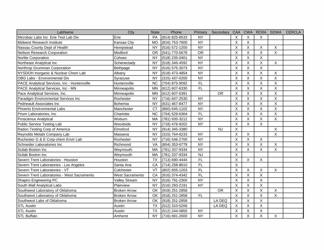
LabName City State Phone Primary Secondary CAA CWA RCRA SDWA CERCLAMicrobac Labs Inc Erie Test Lab Div Erie PA (814) 825-8533 NY X X XMidwest Research Institute Kansas City MO (816) 753-7600 NY X XNassau County Dept of Health Hempstead NY (516) 572-1200 NY X X X XNeilson Research Corporation Medford OR (541) 770-5678 OR X X X XNorlite Corporation Cohoes NY (518) 235-0401 NY X X XNortheast Analytical Inc Schenectady NY (518) 346-4592 NY X X X XNorthrop Grumman Corporation Bethpage NY (516) 575-3073 NY X X XNYSDOH Inorganic & Nuclear Chem Lab Albany NY (518) 473-4854 NY X X X XOBG Labs - Environmental Div Syracuse NY (315) 437-0200 NY X X X XPACE Analytical Services, Inc - Huntersville Huntersville NC (704) 875-9092 FL X X X XPACE Analytical Services, Inc - MN Minneapolis MN (612) 607-6330 FL X X X XPace Analytical Services, Inc. Minneapolis MN (612) 607-6391 OR X X X XParadigm Environmental Services Inc Rochester NY (716) 647-2530 NY X X X XPedneault Associates Inc Bohemia NY (631) 467-8477 NY X X X XPhoenix Environmental Labs Manchester CT (860) 645-1102 NY X X X XPrism Laboratories, Inc Charlotte NC (704) 529-6364 FL X X X XProscience Analytical Woburn MA (781) 935-3212 NY X X X XPublic Service Testing Lab Woodside NY (718) 476-9202 NY X X XRadon Testing Corp of America Elmsford NY (914) 345-3380 NJ X XReynolds Metals Company Lab Massena NY (315) 764-6233 NY X X XRochester G & E Corp-chem Envir Lab Rochester NY (716) 546-2700 NY X X XSchneider Laboratories Inc Richmond VA (804) 353-6778 NY X X X XScilab Boston Inc Weymouth MA (781) 337-9334 NY X X X XScilab Boston Inc Weymouth MA (781) 337-9334 NJ XSevern Trent Laboratories - Houston Houston TX (713) 690-4444 FL X X XSevern Trent Laboratories - Los Angeles Santa Ana CA (714) 258-8610 FL XSevern Trent Laboratories - VT Colchester VT (802) 655-1203 FL X X X XSevern Trent Laboratories - West Sacramento West Sacramento CA (916) 374-4342 FL X X XShapiro Engineering PC Valley Stream NY (516) 791-2300 NY X X XSouth Mall Analytical Labs Plainview NY (516) 293-2191 NY X X XSouthwest Laboratory of Oklahoma Broken Arrow OK (918) 251-2858 OR X X X XSouthwest Laboratory of Oklahoma Broken Arrow OK (918) 251-2858 FL X X X XSouthwest Labs of Oklahoma Broken Arrow OK (918) 251-2858 LA DEQ X X XSTL Austin Austin TX (512) 310-5206 LA DEQ X X XSTL Austin Austin TX (512) 244-0855 NY X X XSTL Buffalo Amherst NY (716) 691-2600 NY X X X X
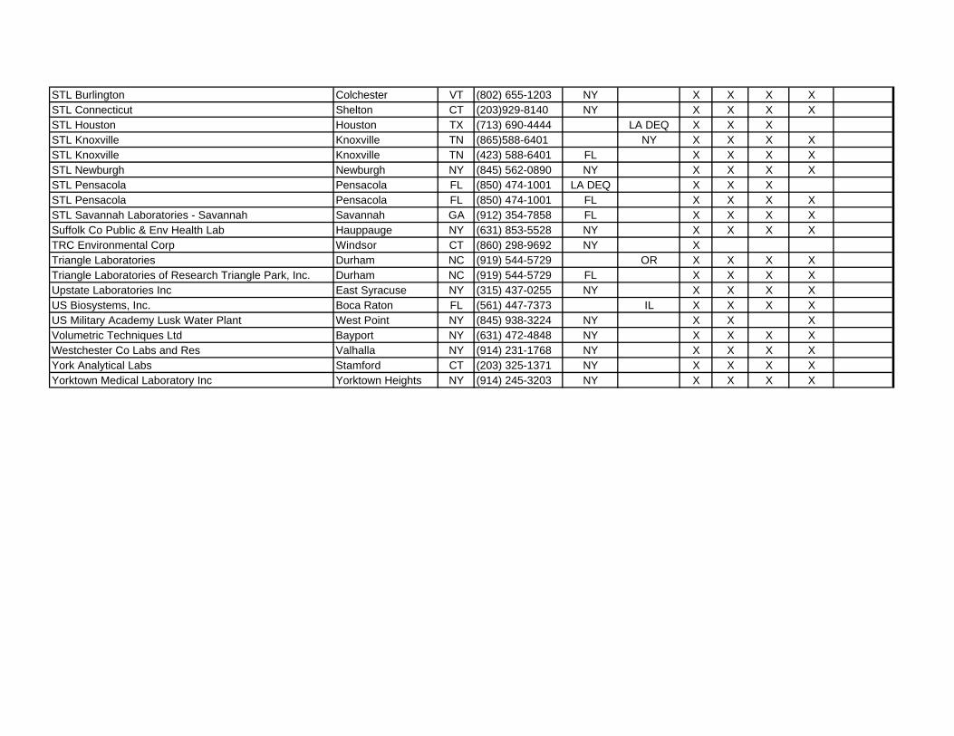
STL Burlington Colchester VT (802) 655-1203 NY X X X XSTL Connecticut Shelton CT (203)929-8140 NY X X X XSTL Houston Houston TX (713) 690-4444 LA DEQ X X XSTL Knoxville Knoxville TN (865)588-6401 NY X X X XSTL Knoxville Knoxville TN (423) 588-6401 FL X X X XSTL Newburgh Newburgh NY (845) 562-0890 NY X X X XSTL Pensacola Pensacola FL (850) 474-1001 LA DEQ X X XSTL Pensacola Pensacola FL (850) 474-1001 FL X X X XSTL Savannah Laboratories - Savannah Savannah GA (912) 354-7858 FL X X X XSuffolk Co Public & Env Health Lab Hauppauge NY (631) 853-5528 NY X X X XTRC Environmental Corp Windsor CT (860) 298-9692 NY XTriangle Laboratories Durham NC (919) 544-5729 OR X X X XTriangle Laboratories of Research Triangle Park, Inc. Durham NC (919) 544-5729 FL X X X XUpstate Laboratories Inc East Syracuse NY (315) 437-0255 NY X X X XUS Biosystems, Inc. Boca Raton FL (561) 447-7373 IL X X X XUS Military Academy Lusk Water Plant West Point NY (845) 938-3224 NY X X XVolumetric Techniques Ltd Bayport NY (631) 472-4848 NY X X X XWestchester Co Labs and Res Valhalla NY (914) 231-1768 NY X X X XYork Analytical Labs Stamford CT (203) 325-1371 NY X X X XYorktown Medical Laboratory Inc Yorktown Heights NY (914) 245-3203 NY X X X X

index
Home - Contacts - Need Help? - SearchN.C. Division of Pollution Prevention and Environmental Assistance
1639 Mail Service Center - Raleigh, NC 27699-1639 - (919) 715-6500
http://www.p2pays.org/ref/07/06643.htm [1/31/2003 12:06:37 PM]
Large Shipyards in Washington: P2 &BMP OpportunitiesA Northwest Industry Roundtable Report
Last Updated: 6 November 1997
Cover Title: Pollution Prevention atShipyards
Table of ContentsReport Sections PDF Format
AcknowledgementsPDF (36KB)
(also includes report cover page andtable of contents)
IntroductionReasons for the RoundtableWashington Shipyard Industry
BackgroundEnvironmental IssuesSummary of Pollution Prevention Opportunities
Roundtable AgendaAKART study
BackgroundMedia TestingIssues
Total Cost AssessmentAlternatives to Abrasive Dry Grit Blasting
Ultra High-Pressure Water Blasting With Hand HeldUnitsHigh-Pressure Water Blasting with RoboticallyDriven Unit
PDF (72KB)
Pollution Prevention at Shipyards — Table of Contents
http://www.p2pays.org/ref/07/06643/ (1 of 2) [1/31/2003 12:06:37 PM]
Wetted Grit Blasting
Best Management Practices
BMP OpportunitiesBarriers to Implementation
Recommendations
Appendix A: Shipyard Roundtable Attendees PDF (34KB)
Appendix B: Environmental Regulations Affecting Shipyards PDF (39KB)
Appendix C: Shipyard Best Management Practices PDF (47KB)
Appendix D: Contacts and Information Resources PDF (54KB)
Appendix E: Glossary PDF (32KB)
Created by the Pacific Northwest Pollution Prevention Research Center, 1326 Fifth Ave, Suite 650, Seattle, WA 98101phone: (206) 223-1151, fax: (206) 223-1165, e-mail: [email protected], WWW address: http://www.pprc.org/pprc/
© 1999, Pacific Northwest Pollution Prevention Resource Centerphone: 206-223-1151, e-mail: [email protected], web: www.pprc.org
Home - Contacts - Need Help? - SearchN.C. Division of Pollution Prevention and Environmental Assistance
1639 Mail Service Center - Raleigh, NC 27699-1639 - (919) 715-6500
Pollution Prevention at Shipyards — Table of Contents
http://www.p2pays.org/ref/07/06643/ (2 of 2) [1/31/2003 12:06:37 PM]
Search This Site
As an agency of the U.S. Department ofTransportation, the mission of theMaritime Administration (MARAD) is topromote the development andmaintenance of an adequate,well-balanced United States merchantmarine, sufficient to carry the Nation'sdomestic waterborne commerce and asubstantial portion of its waterborneforeign commerce, and capable ofserving as a naval and military auxiliaryin time of war or national emergency.
Welcome to the Maritime Administration
Maritime Administration Activates ReadyReserve Force Ships
TheCapeIntrepid,one of 13ReadyReserveForcevesselsactivated.
The U.S. Department of Transportation’s Maritime Administration activated13 Ready Reserve Force (RRF) ships on Friday, Jan. 24 to supportOperation Enduring Freedom. The activations follow orders received fromthe U.S. Navy’s Military Sealift Command. Click here for more information.
Headlines
New Reemployment Rights for U.S. Merchant Seamen
New Secretary Mineta Announces $148 million forTransportation Security Programs to Fund Port, IntercityBus, and Cargo Grants
New MARAD Enhances Web Site for Humanitarian FoodAid Program
New The Maritime Administration has received the firstmonthly bills-of-lading submission filed electronically.
New Port Security information now online
New Short Sea Shipping information now online
Reserve Fleet Tech Library now online
MARAD launches Cargo Service Web Site to assistcustomers in identifying U.S.-flag carriers.
EXIM Bank Form F now available online (monthlyReport of Ocean Shipments moving underExport-Import Bank Financing)
more news...
On Deck>MaritimeAdvisories>PortSecurity>MaritimeWeather
From theBridge
>Meet theAdministrator>Administrator'sOffice>Mission, Goalsand Vision
Offices andDepartments
>Administration>Policy &InternationalTrade>FinancialApprovals &CargoPreference>NationalSecurity>Shipbuilding>Port,Intermodal &EnvironmentalActivities>North AtlanticRegion>Great LakesRegion>CentralRegion>South AtlanticRegion>WesternRegion>Chief Counsel>Civil Rights>Congressional& Public Affairs>Research &Development
Training,Education &Employment
>U.S. MerchantMarineAcademy>State MaritimeAcademies
Maritime Administration - U.S. Department of Transportation
http://marad.dot.gov/ (1 of 2) [1/31/2003 12:31:02 PM]
>GlobalMaritime &TransportationSchool>NationalMaritimeResource &EducationCenter>MarinerEmploymentand Retention>MaritimeFirefightingTraining
MediaInformation
>NewsInformationCenter>Press BookAnnouncements>Speeches>Fact Sheets>FeatureArticles>Newsletters
Kids &Educators
>Education
>Adopt-a-ShipProgram>Photographs
-
Quick jump to MARAD maritime industry servicesand forms.
Access | FOIA | Help |
Contact the Office of Congressional & Public Affairs (email [email protected]) for information about the Agency and/or the maritime industry.
Maritime Administration - U.S. Department of Transportation
http://marad.dot.gov/ (2 of 2) [1/31/2003 12:31:02 PM]
This is an Official US Navy WebsiteThis information resides on a DoD interest computer. Important conditions, restrictions, and disclaimers apply
Privacy and Security Notice
U. S. Naval Shipyards Web site
http://www.shipyards.navy.mil/ (1 of 2) [1/31/2003 12:33:17 PM]
Website of the US Navy
Job Opportunities in the US Navy
U. S. Naval Shipyards Web site
http://www.shipyards.navy.mil/ (2 of 2) [1/31/2003 12:33:17 PM]
TTNWeb - Technology Transfer Network
Recent Additions | Contact Us | Print Version Search:
EPA Home > Air & Radiation > TTNWeb - Technology TransferNetwork
AQS
AMTIC
ATW
CATC / RBLC
CHIEF
CICA
ECAS
EMC
FACA
GEI
NAAQS
NELAC
NSR
OAR P & G
SBAP
SCRAM
TTNWebAir Quality System Advisory Committee for
Ozone and PM
Air Quality Monitoring Geographical/EcosystemsInitiatives
Air Toxics Web site National Ambient AirQuality Standards
Prevention and ControlTechnologies
Lab AccreditationPerformance Standards
Inventories andEmission Factors
New Source ReviewPermitting
U.S. - MexicoInformation Center
OAR Rules, Policy andGuidance
Economic Analysis Small BusinessAssistance Activities
Emission Test Methodsand Information Air Quality Models
About TTNWeb | File Utilities | Public ForumsRelated Sites | New Actions
EPA Home | Privacy and Security Notice | Contact Us
EPA Office of Air Quality Planning & Standards - TTNWeb Home Page
http://epa.gov/ttn/ [1/31/2003 12:34:39 PM]
Pacific NorthwestPollution Prevention Resource Center... the Northwest's leading resource for promoting a cleaner environment through pollutionprevention. PPRC provides high quality, unbiased information, facilitates information exchange, andcatalyzes pollution prevention projects...
Search:
Check It Out!
Quick Sector Finder!
We are a proud member of the Pollution PreventionResource Exchange, P2Rx, a national network ofregional pollution prevention information centers.Through P2Rx, we can provide information retrievalservices from experts around the United States.
Did You Know?
Cut Loads of Energy While Doing the Laundry! It's easy to cut yourenergy costs for laundry. About 80-85% of the energy used forwashing clothes is used to heat the water. You can reduce this cost byusing less water by washing full loads and using cooler water andcold-water detergents - switching the temperature setting from hot towarm cuts a load's energy use in half. You can reduce drying costs aswell: clean the lint filter after every load to improve air circulation, anddon't over-dry clothes. Use the cool-down cycle to allow clothes tofinish drying with residual heat. Also, periodically inspect your dryervent to ensure it's not blocked. For more tips on saving energy at home,visit http://www.energysavers.gov.
last updated: 3 January 2003© 1999, Pacific Northwest Pollution Prevention Resource Center513 1st Ave. W, Seattle, WA 98119phone: 206-352-2050, fax: 206-352-2049e-mail: [email protected], web: www.pprc.orghow to use this sitefeedback
New Metal Finishing ResourceFeatures P2 opportunities, vendors,case studies, and efficiencyworksheets
Environmental MeasurementQuickly find basic environmentalmeasurement information, as well as acompilation of pertinent on-lineresources.
Office Space AvailablePPRC is offering attractive office spaceunder the shadow of the SpaceNeedle!
Sign up for PPRC's freeinformation services
Doing More, With Less(New Year's 2003) All of us promoting pollutionprevention - from corporatepurchasers to governmentpolicymakers - are findingourselves in a fiscal crunch. Theeconomy is in a slump andgovernments and businesses are
Pacific Northwest Pollution Prevention Resource Center
http://www.pprc.org/ (1 of 2) [1/31/2003 12:39:55 PM]

experiencing budget cuts, oftensevere. So, how do we stretch ourability to achieve P2 results?
Pacific Northwest Pollution Prevention Resource Center
http://www.pprc.org/ (2 of 2) [1/31/2003 12:39:55 PM]
Industry Sectors / BusinessAssistance"Staying Competitive through Environmental Compliance andWaste Reduction"
Index: • Resources• Industry Sectors• Contacts
This information is intended to help businesses in the region learn aboutpollution prevention, and how it may help them become more efficientand compliant with environmental regulations.
RESOURCES:
Adhesives & P2 Alternative Fuels Cleaning in Manufacturing Environmental Management System Implementation Guide Environmental Purchasing How to Inventory Your Wastes for Environmental Compliance PBTs P2 Quiz PPRC Publications List Total Cost Accounting
Fact Sheets: Understanding Regulations on Solvent Cleaning Equipment How to Read a Materials Safety Data Sheet Emission Estimating Worksheet List of 189 Hazardous Air Pollutants What You Need to Know About Risk Management Planning Chromium Electroplating and Anodizing Aerospace Manufacturing, Repair Operations Using the Internet to Find Regulatory and P2 Information Is Your Business Using Regulated Chemicals? Calculating True Costs of Paints and Coatings
Northwest Industry Sectors / Business Assistance
http://www.pprc.org/pprc/sbap/sbap.html (1 of 2) [1/31/2003 12:41:01 PM]
CONTACTS:
If you are looking for asingle contact to helpanswer questions aboutcompliance and pollutionprevention, use the list ofNorthwest Small BusinessAssistance ProgramContacts.
If you are seekinginformation about P2 policyor program development,compliance assistance,technical assistance, or otherP2 topics, examine the fulllist of Northwest P2Contacts.
INDUSTRY SECTOR INFORMATION:
Auto Repair Aerospace Fiberglass Fabrication Food Processing Hospitality Industrial Laundries Metal Fabrication Metal Finishing Metal Machining Paint and Coating Manufacturing Printing Semiconductor Manufacturing Ship Building and Repair Wood Furniture Manufacturing
= extensive resources are available online for this sector.
If you have questions or comments about this industry sector and business assistance information, pleasecontact Chris Wiley at 206-352-2050 ([email protected]).
This section of the PPRC Web site is a joint project of the Small Business Assistance Programs inAlaska, Idaho, Oregon and Washington and is funded by a grant from the U.S. Environmental ProtectionAgency, as well as other federal, state and local governments and the industrial community.
© 1999, Pacific Northwest Pollution Prevention Resource Centerphone: 206-352-2050, e-mail: [email protected], web: www.pprc.orghow to use this sitefeedback
Northwest Industry Sectors / Business Assistance
http://www.pprc.org/pprc/sbap/sbap.html (2 of 2) [1/31/2003 12:41:01 PM]
Business AssistanceShip Building and Repair IndustryResources
PPRC's resources for the ship building and repair industry include:
● Northwest Shipyard Industry Roundtable Reports
● Environmental Compliance and P2 Fact Sheets
● Ship Building & Repair Topic Hub - Industry Overview, Descriptions & Links
● Technical and Regulatory Information Links
● Research Projects Links
Many of these files are available to download to your computer as PDF (portable data format) files whichappear on-screen as snapshots of the printed pages and include all formatting. To read and print PDFfiles, you will need to download a free Acrobat Reader from Adobe.
Northwest Shipyard Industry Roundtable ReportsThe purpose of these roundtables were for participants to learn more about alternative pollutionprevention and treatment technologies, become familiar with tools to analyze alternatives, find out howto work productively with government agencies in complying with stormwater regulatory requirements,share experiences and ideas with industry peers, and generate ideas for future projects that will benefitthe environment and the industry.
Large Shipyards in Washington: P2 & BMP Opportunities
Small Shipyards and Boatyards in Oregon: Environmental Issues & P2Opportunities
Large Shipyards in Oregon: Coating Choice Drivers & P2 Opportunities
Depainting Technology Demonstrations: P2 Benefits & Production Issues
Fact SheetsThese fact sheets are intended to inform metal fabricators about the implications of the Clean Air ActAmendments on their businesses and how to achieve compliance through the use of pollution preventionmethods and ideologies.
Ship Building and Repair Industry Resources
http://www.pprc.org/pprc/sbap/ship.html (1 of 5) [1/31/2003 12:41:23 PM]

Understanding Regulations on Solvent Cleaning Equipment: What You Need toKnow to Comply
How to Read a Materials Safety Data Sheet to Determine if You Use RegulatedChemicals
Emission Estimating Worksheet
List of 189 Hazardous Air Pollutants
What You Need to Know About Risk Management Planning
Using the Internet to Find Regulatory and Pollution Prevention Information
Is Your Business Using Regulated Chemicals? Watch Your Profits Evaporate
Shipbuilding and Repair — What You Need to Know To Comply
Evaluating Less Toxic Paints and Coatings ? — Calculate True Costs
Ship Building & Repair Topic Hub - IndustryOverview, Descriptions & Links
Ship Building and Repair Industry LinksThese links include general and specific information of interest to the shipyard industry to preventpollution and comply with environmental regulations.
Technical and Regulatory InformationEnergy User News (http://www.energyusernews.com)This section of the Energy User News (EUN) web site is an energy management training series.The EUN and the Association of Professional Energy Managers designed this series of monthlytraining modules to provide nonspecialists with an introduction to the fundamentals of energymanagement.
●
Enviro$en$e (http://es.epa.gov)Enviro$en$e, part of the U.S. Environmental Protection Agency’s Web site, is a repository forpollution prevention, compliance assurance, and enforcement information and databases. Includedare pollution prevention case studies, technologies, points of contact, environmental statutes,executive orders, regulations, and compliance and enforcement policies and guidelines. The siteincludes a search engine. Two publications of interest to shipyards that can be found on the site areWaste Reduction Guide: Shipyards and Guides to Pollution Prevention: The Marine Maintenanceand Repair Industry.
●
Maritime Environmental Resources & Information Center(http://www.uno.edu/~engr/meric/briefs.html)
●
Ship Building and Repair Industry Resources
http://www.pprc.org/pprc/sbap/ship.html (2 of 5) [1/31/2003 12:41:23 PM]
This site provides links to technical briefs. Some of the technical briefs are related to pollutionprevention measures dealing with paint management, solvent usage, machine shop wastes and spillcleanup.
Research Triangle Institute: Abrasive Blasting Operations (http://clean.rti.org/altern.cfm)This site provides information on alternative blasting technologies such as wheat starch blasting,and includes case studies, economics data, and environmental requirements.
●
SAGE (http://clean.rti.org/altern.cfm)SAGE is expert system software used to determine solvent/process alternatives most likely to workin a given case.
●
Tacoma-Pierce County Health Department Boating Page(http://www.healthdept.co.pierce.wa.us/eh/boat.html)This site contains pollution prevention ideas, boat maintenance tips, and a list of alternative boatmaintenance products.
●
Tri-Services' Pollution Prevention Technical Library (http://p2library.nfesc.navy.mil/)Maintained by the Naval Facilities Engineering Service Center (NFESC), this Web site containsprocess data sheets including information on technology, materials compatibility, safety andhealth, benefits, disadvantages, economic analysis, points of contact and vendors. Online topicsinclude painting, paint removal and stormwater issues.
●
Shipyard Industry Trade AssociationsAmerican Waterways Operators (http://www.ribb.com/awo/awo.htm)The American Waterways Operators is the national association representing the inland and coastaltugboat, towboat, and barge industry. The organization has defined and advocated industry viewswith policymakers and federal officials and promoted a greater understanding of the domesticwaterborne transportation industry's safe and environmentally sound contribution to the U.S.economy.
●
International Marina Institute (http://www.imimarina.com/)This organization is a non-profit membership organization serving the global marina industry withmanagement training and education, research, legislation and information about environmentalissues effecting the marina industry.
●
International Maritime Organization (http://www.imo.org/)The International Maritime Organization is the United Nations' specialized agency responsible forimproving maritime safety and preventing pollution from ships.
●
Marine Technology Society (http://www.phys.washington.edu/~wilkes/mts)The Marine Technology Society is a non-profit international professional organization establishedto promote the exchange of information in ocean and marine engineering, science, and policy.
●
The National Paint and Coatings Association (http://www.paint.org/)The National Paint and Coatings Association is a nonprofit trade group representing some 400paint and coatings manufacturers, raw materials suppliers and distributors in the United States.
●
The Society of Naval Architects and Marine Engineers (http://www.sname.org/)This organization is an internationally recognized nonprofit, technical, professional society of
●
Ship Building and Repair Industry Resources
http://www.pprc.org/pprc/sbap/ship.html (3 of 5) [1/31/2003 12:41:23 PM]

individual members serving the maritime and offshore industries and their suppliers. The Societyof Naval Architects and Marine Engineers (SNAME) is dedicated to advancing the art, science andpractice of naval architecture; shipbuilding and marine engineering; and sponsoring appliedresearch.
Shipyard-related Projects in the Pacific NorthwestPollution Prevention Resource Center's ResearchProjects DatabaseThe PPRC Research Projects Database contains over 500 pollution prevention research anddemonstration projects. Each of the following links will take you to one project listed in the database,and includes a project summary and information about the project researcher and funder. If you wouldlike to learn more about a project, contact the project researcher or funder.
Aircraft Depainting Technology(http://www.pprc.org/pprc/rpd/fedfund/dod/serdp/aircraft.html)
●
Applied Innovative Coatings Research(http://www.pprc.org/pprc/rpd/fedfund/epa/epaappcd/appliedi.html)
●
Bicarbonate of Soda Blasting Technology for Aircraft Wheel Depainting(http://www.pprc.org/pprc/rpd/fedfund/epa/epastd/bicarbon.html)
●
Development and Testing of Pollution Prevention Design Aids for Process Analysis and DecisionMaking(http://www.pprc.org/pprc/rpd/fedfund/epa/epaeed/develop1.html)
●
Environmental Fate and Risk Assessment Tool (EFRAT)(http://www.pprc.org/pprc/rpd/fedfund/epa/epaeed/environ1.html)
●
Evaluation of Alternative Paint Stripping Technologies Used in Aircraft and Space Vehicles(http://www.pprc.org/pprc/rpd/fedfund/epa/epaappcd/evaluat2.html)
●
Evaluation of Five Waste Minimization Technologies at the General Dynamics Pomona Division:Robotic Painting(http://www.pprc.org/pprc/rpd/fedfund/epa/epastd/evalrobo.html)
●
Evaluation of New Multi-component HVLP Spray Equipment For the Application of LinearPolyurethane Exterior Paint to Fiberglass Yachts(http://www.pprc.org/pprc/rpd/statefnd/nc_owr/evaluat2.html)
●
Fluorinated Ship-Hull Coatings for Non-Polluting Fouling Control(http://www.pprc.org/pprc/rpd/fedfund/dod/serdp/fluorina.html)
●
Identification of Chemical Coating/Depainting Alternatives for Selected DoD Operations(http://www.pprc.org/pprc/rpd/fedfund/epa/epastd/identifi.html)
●
Ship Building and Repair Industry Resources
http://www.pprc.org/pprc/sbap/ship.html (4 of 5) [1/31/2003 12:41:23 PM]
Large Aircraft Robotic Paint Stripping (LARPS)(http://www.pprc.org/pprc/rpd/fedfund/dod/serdp/largeair.html)
●
Large Area Powder Coating(http://www.pprc.org/pprc/rpd/fedfund/dod/serdp/largeare.html)
●
Organic Protective Coatings and Application Technology(http://www.pprc.org/pprc/rpd/fedfund/dod/serdp/organicp.html)
●
Overspray Paint Recycled at Caterpillar, Inc.(http://www.pprc.org/pprc/rpd/fedfund/doe/doe_oit/overspra.html)
●
Pollution Prevention of an Electrodeposition Coating and Pre-treatment System(http://www.pprc.org/pprc/rpd/fedfund/epa/epaeed/p2ecoat.html)
●
Recycle Boiler Nitrite Solution(http://www.pprc.org/pprc/rpd/fedfund/dod/serdp/recy_boi.html)
●
Reducing Use of Fast-Evaporating Solvents in Paint and Coating Equipment(http://www.pprc.org/pprc/rpd/statefnd/minn_oea/reducin2.html)
●
Spray Gun Cleaning(http://www.pprc.org/pprc/rpd/fedfund/epa/epaappcd/spraygun.html)
●
If you have questions or comments about this business information, please send an e-mail message toChris Wiley at [email protected].
Back to the main Business Assistance page.
Created by the Pacific Northwest Pollution Prevention Resource Center, 513 First Ave. West, Seattle, WA 98119phone: 206-352-2050, fax: 206-352-2049, e-mail: [email protected], WWW address: http://www.pprc.org
This section of the PPRC Web site is a joint project of the Business Assistance Programs in Alaska, Idaho, Oregon andWashington and is funded by a grant from the U.S. Environmental Protection Agency.
© 1999, Pacific Northwest Pollution Prevention Resource Centerphone: 206-352-2050, e-mail: [email protected], web: www.pprc.orghow to use this sitefeedback
Ship Building and Repair Industry Resources
http://www.pprc.org/pprc/sbap/ship.html (5 of 5) [1/31/2003 12:41:23 PM]
UNITED STATES ENVIRONMENTAL PROTECTION AGENCYOFFICE OF ENFORCEMENT
EPA-330/9-89-003-R
MULTI-MEDIA INVESTIGATION MANUAL
Revised March 1992
NATIONAL ENFORCEMENT INVESTIGATIONS CENTERDenver, Colorado
Prepared in cooperation with Environmental Services DivisionsRegions I through X
Mention of commercial names is for example purposes and does not constitute endorsement by EPA.
Additionally, this manual supplements, not supersedes, Standard Operating Procedures, Policy and
Procedures Manuals, and any other EPA guidance.
i
CONTENTS
INTRODUCTION . . . . . . . . . . . . . . . . . . . . . . . . . . . . . . . . . . . . . . . . . . . . . . . . . . . . . . . . . . . 1Purpose and Scope of this Manual . . . . . . . . . . . . . . . . . . . . . . . . . . . . . . . . . . . . . . . . . 5
PROJECT REQUEST/IDENTIFICATION . . . . . . . . . . . . . . . . . . . . . . . . . . . . . . . . . . . . . . . . 8
PROJECT TEAM FORMATION . . . . . . . . . . . . . . . . . . . . . . . . . . . . . . . . . . . . . . . . . . . . . . . 9
REQUIRED SKILLS AND QUALIFICATIONS . . . . . . . . . . . . . . . . . . . . . . . . . . . . . 9INVESTIGATOR RESPONSIBILITY . . . . . . . . . . . . . . . . . . . . . . . . . . . . . . . . . . . . 11
BACKGROUND INFORMATION REVIEW . . . . . . . . . . . . . . . . . . . . . . . . . . . . . . . . . . . . . 12
FEDERAL/STATE/LOCAL FILE REVIEW . . . . . . . . . . . . . . . . . . . . . . . . . . . . . . . 12RECONNAISSANCE . . . . . . . . . . . . . . . . . . . . . . . . . . . . . . . . . . . . . . . . . . . . . . . . . 13EPA DATABASE REVIEWS . . . . . . . . . . . . . . . . . . . . . . . . . . . . . . . . . . . . . . . . . . . 13
PROJECT PLAN DEVELOPMENT . . . . . . . . . . . . . . . . . . . . . . . . . . . . . . . . . . . . . . . . . . . . 15
PROJECT PLAN . . . . . . . . . . . . . . . . . . . . . . . . . . . . . . . . . . . . . . . . . . . . . . . . . . . . 15NOTIFICATIONS/SCHEDULING . . . . . . . . . . . . . . . . . . . . . . . . . . . . . . . . . . . . . . 17
FIELD INSPECTION . . . . . . . . . . . . . . . . . . . . . . . . . . . . . . . . . . . . . . . . . . . . . . . . . . . . . . . 19
DEVELOPING AN INSPECTION STRATEGY . . . . . . . . . . . . . . . . . . . . . . . . . . . . 19CONDUCTING THE ON-SITE INSPECTION . . . . . . . . . . . . . . . . . . . . . . . . . . . . . 23
Entry . . . . . . . . . . . . . . . . . . . . . . . . . . . . . . . . . . . . . . . . . . . . . . . . . . . . . . . 23Opening Conference . . . . . . . . . . . . . . . . . . . . . . . . . . . . . . . . . . . . . . . . . . . . 25General Facility Tour . . . . . . . . . . . . . . . . . . . . . . . . . . . . . . . . . . . . . . . . . . . 28Questioning Facility Personnel . . . . . . . . . . . . . . . . . . . . . . . . . . . . . . . . . . . . 29Document Reviews . . . . . . . . . . . . . . . . . . . . . . . . . . . . . . . . . . . . . . . . . . . . . 31Sampling . . . . . . . . . . . . . . . . . . . . . . . . . . . . . . . . . . . . . . . . . . . . . . . . . . . . 32Closing Conference . . . . . . . . . . . . . . . . . . . . . . . . . . . . . . . . . . . . . . . . . . . . . 33
MEDIA SPECIFIC INVESTIGATION PROCEDURES . . . . . . . . . . . . . . . . . . . . . . . . . . . . . 35
RESOURCE CONSERVATION AND RECOVERY ACT (RCRA) . . . . . . . . . . . . . . 35Basic Program . . . . . . . . . . . . . . . . . . . . . . . . . . . . . . . . . . . . . . . . . . . . . . . . 35Generators . . . . . . . . . . . . . . . . . . . . . . . . . . . . . . . . . . . . . . . . . . . . . . . . . . . 37Transporters . . . . . . . . . . . . . . . . . . . . . . . . . . . . . . . . . . . . . . . . . . . . . . . . . . 39Treatment, Storage, and Disposal Facilities . . . . . . . . . . . . . . . . . . . . . . . . . . . 40Land Disposal Restrictions . . . . . . . . . . . . . . . . . . . . . . . . . . . . . . . . . . . . . . . 46Subtitle I - Underground Storage Tanks (USTs) . . . . . . . . . . . . . . . . . . . . . . . 48
ii
Subtitle J - Medical Wastes . . . . . . . . . . . . . . . . . . . . . . . . . . . . . . . . . . . . . . . 50Pollution Prevention . . . . . . . . . . . . . . . . . . . . . . . . . . . . . . . . . . . . . . . . . . . . 53
CLEAN WATER ACT (CWA) . . . . . . . . . . . . . . . . . . . . . . . . . . . . . . . . . . . . . . . . . . 55
Basic Program . . . . . . . . . . . . . . . . . . . . . . . . . . . . . . . . . . . . . . . . . . . . . . . . 55Evaluating Compliance . . . . . . . . . . . . . . . . . . . . . . . . . . . . . . . . . . . . . . . . . . 56
CLEAN AIR ACT (CAA) . . . . . . . . . . . . . . . . . . . . . . . . . . . . . . . . . . . . . . . . . . . . . . 59
Basic Program . . . . . . . . . . . . . . . . . . . . . . . . . . . . . . . . . . . . . . . . . . . . . . . . 59Evaluating Compliance . . . . . . . . . . . . . . . . . . . . . . . . . . . . . . . . . . . . . . . . . . 61
SAFE DRINKING WATER ACT (SDWA) . . . . . . . . . . . . . . . . . . . . . . . . . . . . . . . . 63
Basic Program . . . . . . . . . . . . . . . . . . . . . . . . . . . . . . . . . . . . . . . . . . . . . . . . 63Evaluating Compliance . . . . . . . . . . . . . . . . . . . . . . . . . . . . . . . . . . . . . . . . . . 64
TOXIC SUBSTANCES CONTROL ACT (TSCA) . . . . . . . . . . . . . . . . . . . . . . . . . . . 65
Basic Program . . . . . . . . . . . . . . . . . . . . . . . . . . . . . . . . . . . . . . . . . . . . . . . . 66Evaluating Compliance . . . . . . . . . . . . . . . . . . . . . . . . . . . . . . . . . . . . . . . . . . 67
FEDERAL INSECTICIDE, FUNGICIDE, AND RODENTICIDE ACT (FIFRA) . . . 74
Basic Program . . . . . . . . . . . . . . . . . . . . . . . . . . . . . . . . . . . . . . . . . . . . . . . . 74Evaluating Compliance . . . . . . . . . . . . . . . . . . . . . . . . . . . . . . . . . . . . . . . . . . 74
EMERGENCY PLANNING AND COMMUNITY RIGHT-TO-KNOW ACT (EPCRA) . . . . . . . . . . . . . . . . . . . . . . . . . . . . . . . . . . . 76
Basic Program . . . . . . . . . . . . . . . . . . . . . . . . . . . . . . . . . . . . . . . . . . . . . . . . 76Evaluating Compliance . . . . . . . . . . . . . . . . . . . . . . . . . . . . . . . . . . . . . . . . . . 77
COMPREHENSIVE EME RGENCY RESPONSE, COMPENSATION, AND LIABILITYACT (CERCLA) . . . . . . . . . . . . . . . . . . . . . . . . . . . . . . . . . . . . . . . . . . . . . . 79
LABORATORY AND DATA QUALITY AUDITS . . . . . . . . . . . . . . . . . . . . . . . . . . 80
FIELD CITATIONS AND DOCUMENTATION . . . . . . . . . . . . . . . . . . . . . . . . . . . . 83
Field Citations . . . . . . . . . . . . . . . . . . . . . . . . . . . . . . . . . . . . . . . . . . . . . . . . 84Other Facility Material . . . . . . . . . . . . . . . . . . . . . . . . . . . . . . . . . . . . . . . . . . 84Project Logbook . . . . . . . . . . . . . . . . . . . . . . . . . . . . . . . . . . . . . . . . . . . . . . . 84Chain-of-Custody . . . . . . . . . . . . . . . . . . . . . . . . . . . . . . . . . . . . . . . . . . . . . . 85Photographs . . . . . . . . . . . . . . . . . . . . . . . . . . . . . . . . . . . . . . . . . . . . . . . . . . 85
INVESTIGATION REPORT . . . . . . . . . . . . . . . . . . . . . . . . . . . . . . . . . . . . . . . . . . . 85
iii
OCCUPATIONAL SAFETY AND HEALTH ADMINISTRATION . . . . . . . . . . . . . . 87
REFERENCES . . . . . . . . . . . . . . . . . . . . . . . . . . . . . . . . . . . . . . . . . . . . . . . . . . . . . . . . . . . . 88
APPENDICES
A Summary of Pollution Control LegislationB Multi-Media Inspections - Definitions and TrainingC Team Leader REsponsibilities and AuthoritiesD Types of InformationE Sources of InformationF Project Plan and Safety Plan ExamplesG Multi-Media Investigation Equipment ChecklistH Suggested Records/Document RequestI Multi-Media ChecklistsJ Investigation Authority/Summary of Environmental ActsK Evidentiary Procedures for Photographs/MicrofilmL Key Principles and Techniques for InterviewingM Sampling GuidelinesN Land Disposal Restrictions ProgramO Sources Subpart (40 CFR Part 60) Effective Date of
Standard Air Pollutants Subject to NSPSP TSCA FormsQ TSCA Sections 5 and 8 Glossary of Terms and Acronyms
INTRODUCTION
1
INTRODUCTIONThis manual is intended as a guide for investigators who conduct multi-media
environmental compliance investigations of facilities that discharge, emit, prepare, manage,
store, or dispose of pollutants controlled by Federal, State, or local environmental laws and
regulations. Investigative methods are presented t hat integrate the enforcement programs for
air, water, solid waste, pesticides, and toxic substances. This manual describes general
activities and functions of multi-media investigations, and provides information on special
features of specific media and associated s tatutes. This manual is intended to supplement the
various media-specific investigation guides listed in the reference section.
Multi-media compliance investigations are intended to determine a facility's status of
compliance with applicable laws, regulations, and permits.
The environmental laws which EPA administers and enforces are summarized in
Appendix A. Emphasis is given to identifying violations of regulations, permits, approvals,
orders and consent decrees, and the underlying causes of such violations. Investigators
should thoroughly identify and document violations and problems that have an existing or
potential effect on human health and the environment.
All inspections can be grouped i nto four categories of increasing complexity, moving
from Category A (a program-specific compliance inspection) to Category D, (a complex
multi-media investigation) depending upon the complexity of the facility and the objectives
of the investigation. Factors in categorizing the investigation include the complexity of
pollution sources, f acility size, process operations, pollution controls, and the personnel and
time resources which are required to conduct the compliance investigation. The four
categories of investigations are described below [Appendix B]:
Category A: Program-specific compliance inspections, conducted by one or more
inspectors. The objective is to determine facility compliance status for
program-specific regulations.
Category B : Program-specific compliance inspections (e.g., compliance with hazardous
waste regulations), which are conducted by one or more inspectors; however,
INTRODUCTION
2
the inspector(s) screen for and report on obvious, key indicators of possible
noncompliance in other environmental program areas.
Category B mu lti-media inspections have limited, focused objectives and are
most appropriate for smaller, less complex facilities that are subject to only a
few environmental laws. The objective is to determine compliance for
program specific regulations and to refer infor mation to other programs based
on screening inspections.
Category C : Several concurrent and coordinated program-specific compliance
investigations conducted by a t eam of investigators representing two or more
program offices. The team, which is headed by a team leader, conducts a
detailed compliance evaluation for each of the target programs.
Category C multi-media investigations have more compliance issues to
address than the Category B inspection and are more appropriate for
intermediate to large facilities that are subject to a variety of environmental
laws. The objective is to determine c ompliance for several targeted program-
specific areas. Reports on obvi ous, key indicators of possible noncompliance
in other environmental program areas are also made.
Category D : These comprehensive facility evaluations address not only compliance in
targeted program specific regulations, but also try to identify environmental
problems that might otherwise be overlooked. The initial focus is normally
on facility processes to identify activities (e.g., new chemical manufacturing)
and byproducts/waste streams potentially subject to regulation. The
byproducts/waste streams are traced to final disposition (on-site or off-site
treatment, storage, and/or disposal). When regulated activities or waste
streams are identified, a compliance evaluation is made with respect to
applicable requirements.
The investigation team, headed by a team leader, is comprised of staff
thoroughly trained in different pr ogram areas. For example, a large industrial
INTRODUCTION
3
facility with multiple process operations may be regulated under numerous
environmental statutes, such as the Clean Water Act (CWA), Clean Air Act
(CAA), Resource Conservation and Recovery Act (RCRA) , Toxic Substances
Control Act (TSCA), Comprehensive Environmental Response,
Compensation and Liability Act (CERCLA), and the Federal Insecticide and
Rodenticide Act (FIFRA). T he on-site investigation is conducted during one
or more time periods, during which intense concurrent program-specific
compliance evaluations are conducted, often by the same cross-trained
personnel.
Category D multi-media investigations are thorough and, consequently,
resource intensive. They are appropriate for intermediate to large, complex
facilities that are subject to a variety of environmental laws. Compliance
determinations are made for several target ed program-specific areas. Reports
on possible noncompliance are made for other program areas.
Generally, all investigations will use essentially the same protocols, including pre-
inspection plann ing, use of a project plan, sampling, inspection procedures, and final report.
The major difference will be in the number of different regulations Categories C and D
investigations address.
The multi-media approach to investigations (which is described in Categories C and
D) has several advantages over a program-specific inspection, including:
A more comprehensive and reli able assessment of a facility's compliance with
fewer missed violations
Improved enforcement support and better potential for enforcement
A higher probability to uncover/preven t problems before they occur or before
they manifest an environmental or public health risk
INTRODUCTION
4
Ability to respond more effectively to non-program specific complaints,
issues, or needs a nd develop a better understanding of cross-media problems
and issues, such as waste minimization
The success of a multi-media investigation program is contingent upon a good
managerial system and the support of upper management. Since these investigations will
often be conducted at larger facilities, adequate resources (time and personnel) must be
provided. Good communicati ons during the planning phase are essential to define the scope
of work and each team m ember's role in the inspection. Communications could also include
state officials sinc e state inspectors might also participate as team members. Often, because
of the extent of the state's knowledge of the facility and its problems, state involvement is
critical to the success of the investigation. Similarly, coordination with other Federal or local
agencies needs to be addressed, as necessary.
Branch Chiefs and Section Chiefs are important in implementing the multi-media
inspection prog ram and identifying areas of responsibility and accountability. Some of their
duties include:
Identify team leaders
Form investigation teams
Provide access to traini ng and other means necessary to develop multi-media
investigation expertise
Participate in targeting investigations
Ensure that team activities both internal and external to their Divisions are
coordinated
Market multi-media investigations to programs
Oversee the preparation of a site -specific project plan and safety plan prior to
the investigation
Provide managerial support while teams are in the field
Ensure quality of final reports
The roles and areas of responsibility and accountability of other managers, technical
staff, and team leaders must be defined. Participants need to identify and agree on what
INTRODUCTION
5
evidence is needed and the scope of work to be conducted. Next, a project plan and safety
plan that outlines the desired objectives and safety considerations must next be prepared by
the team leader. Other responsibilities for the technical staff, which often mirror or
complement those of managers, are as follows:
Contact state counterparts
Assist in investigation preparation, including logistical considerations
Coordinate activities internal and external to their Division
Provide legal support for obtaining warrants when necessary
Provide training for investigators
Prepare reports
Distribute reports and followup for multi-media enforcement
Purpose and Scope of this Manual
Multi-media investigations are carried out in response to specific requests from the
EPA program offices, legal staff, or stat e environmental offices. All investigations will result
in a written report that documents non-compliance or ot her areas of concern identified during
the investigation. Report guidelines for documenting a multi-media investigation are
discussed later in this document.
This manual provides guidelines for conducting Categories C and D multi-media
investigations, as well as, suggests principles and procedures which will also apply to
Categories A and B or single media investigations. Moreover, this manual identifies multi-
media objectives and also focuses on specific environmental laws and associated statutes.
The manual's organization follows the steps involved in a multi-media investigation
beginning with the project request and leading ultimately to enforcement case support.
Multi-media investigations are conducted as a series of tasks or phases, which usually
include:
Project request/identification of objectives
Project team formation
INTRODUCTION
6
Background information review
Project Plan preparation
On-site field inspection
Report preparation
Enforcement case support
These phases are depicted in Figur e 1 and discussed in detail in the following sections. Each
phase is not necessarily a discrete step to be completed, in order, before initiating the next
phase. The background information review, for example, usually continues through
enforcement case support.
Where established p olicies and procedures do not exist, common sense, professional
judgment, and experience should be applied. Investigators need to collect valid, factual
information and supporting data to document violations adequatel y. The documentation must
be admissible as evidence in any subsequent enforcement action.
Figure 1 - Project Phases (Missing)
Each investigation should be conducted as though it will be contested in court. The
investigation and all supporting evidence and documentation may be contested by highly
skilled defense counsel as unprofessional, inaccurate, misinterpreted, etc. Because the
Agency's case will depend heavily on the investigative findings, the investigation must be
complete and accurate.
Since a multi-media investigation by its very nature probes into a facility's processes
under multiple environmental regulations, it provides a highly effective way of looking at a
non-complying facility. Overall objectives of a multi-media investigation include:
Determine compliance status with applicable laws, regulations, permits, and
consent decrees
INTRODUCTION
7
Determine ability of a facility to achieve compliance across all environmental
areas
Identify need for remedial measures and enforcement action(s) to correct the
causes of violations
Evaluate a facility's waste producing, treatment, management, and pollution
control practices and equipment
Evaluate facility self-monitoring capability
Evaluate facility recordkeeping practices
Evaluate facility waste minimization/pollution prevention programs
Obtain appropriate samples
PROJECT REQUEST/IDENTIFICATION
8
PROJECT REQUEST/IDENTIFICATIONThe success of a multi-media investigation depends on thorough, up-front planning.
Coordination with all interested and knowledgeable parties [i.e., Region, State, National
Enforcement Investigations Center (NEIC), investigation team members, supervisory staff]
is essential to ensure an effi cient and thorough investigation. Each program office should be
contacted to assure that all interested parties are aware of the planned multi-media
investigation. Fur thermore, depending upon State/EPA agreements, the State should (may)
be notified of the pending investi gation. All concerned parties should be involved as soon as
possible to facilitate coordination. Coordination with other Federal agencies, such as
Occupat ional Safety and Health Administration (OSHA) or Corps of Engineers, may be
needed in joint Federal investigations.
There must be agreement on the part of program and support offices and Regional
Counsel, and perhaps the State as well, on the overall scope of work for a particular
investigation. The scope must be clearly communicated to managers and the investigators and
stated in the project plan. Clearly defined objectives are critical to the success of any
investigation; the objectives should be well defined at the time of the initial request. At the
time the project plan is developed, the objectives will be further refined (see section titled
Project Plan Formation). Communication among the involved parties should be the initial
step of pre-investigation planning but should also continue throughout the investigation,
because of unanticipated events often associated with field work.
PROJECT TEAM FORMATION
9
PROJECT TEAM FORMATION
REQUIRED SKILLS AND QUALIFICATIONS
Each multi-media investigation team should be compose d of qualified field inspectors.
Each team membe r should bring special program expertise and experience and must be well
trained in most facets of conducting a field investigation, including sampling.
Most of the investigators on the team, including the team leader, should be current
field investigators who already possess most of the necessary skills and qualifications.
However, flexibility in team sel ection must exist in order to use skills in the organization and
ensure that the expertise is represented for a given situation. There may be circumstances
where a permit writer, hydrogeologist, toxicologist, or some other special discipline will be
needed on the team.
The team leader has o verall responsibility for the successful completion of the multi-
media investigation. (Team leader responsibilities and authorities are presented in Appendix
C.) In addition, other investigators may be designated as leads for each of the specific
media/programs that will be addressed. These individuals may work alone or have one or
more inspectors/samplers as assistants, depending on workloads and training objectives.
However, all investigation team members should report direct ly to, and be accountable to, the
team leader.
Some of the more important skills and qualifications that are necessary for team
members, are as follows:
Knowledge of the Agency's policies and procedures regarding
inspection authority, entry procedure s/problems, enforcement actions,
legal issues, and safety
Thorough familiarity with sampling equipment, qualit y assurance (QA)
requirements for sample collection, identification and preservation,
and chain-of-custody procedures
Knowledge of manufacturing/waste producing processes, pollution
control technology, principles of waste management, flow
PROJECT TEAM FORMATION
10
measurement theory and procedures, and waste monitoring
techniques/equipment
Investigatory skills including ability to gather evidence through good
interviewing techniques and astute observations
Up-to-date experience in conducting compliance inspections
Communication skills
Basic understanding of the procedures for obtaining administrative
warrants, including preparation of affidavits, technical content of the
warrant application, and warrant and proc edures for serving a warrant
For each of the areas addressed in the multi-media investigations,
there should be at least one team member trained in that area.
Furthermore, at least one team member should have considerable
knowledge of laboratory (analytical) methods and quality assurance
(QA) requirements, if a laboratory evaluation is to be conducted.
EPA Order 3500.1 sets forth specific trai ning requirements for any EPA investigator
who is leading a single media investigation. These training req uirements include both general
inspection procedures and media specific procedures. While an individual leading a multi-
media investigation may not have had the media-specific training for each media covered
during that multi-media investigation, the team leader s hould have the media specific training
for at least two of the media . In addition, the team leader should have experience and skills
in the following areas.
Leadership
Project management
Lead for inspections in more than one program/media
Multi-media investigations
PROJECT TEAM FORMATION
Field conditions may dictate plan modifications. Reasons for modifications should be*
thoroughly documented.
11
INVESTIGATOR RESPONSIBILITY
Investigators must conduct themselves in a professional manner and maintain
credibility. A cooperative spirit should be cultivated with facility representatives, when
possible. All investigators should maintain a sensitivity to multi-media issues and implications
and freely discuss, with other members of the team, observations/findings relating to one or
more programs (or cross-program lines). Moreover, investigators must remember to adhere
to the projec t plan, as well as both the Agency's and the facility's safety plans or1
requirements.
Investigators should restrict their on-site activit ies to the normal working hours of the
facility, as much as possible. Investigators will need to keep abreast of specific program
regulations and should also coordinate, as necessary, with other EP A and State inspectors and
laboratory staff (if samples will be collected). The investigation team should implement
appropriate field no te taking methods and proper document control procedures, particularly
when the company asserts a "confidential" claim. Investigators must assume that important
documents (e.g., project plan, safety plan, and logbooks) are not left unattended at the
facility. Sensitive discussions do not take place in front of facility personnel or on company
telephones.
BACKGROUND INFORMATION REVIEW
12
BACKGROUND INFORMATION REVIEW
FEDERAL/STATE/LOCAL FILE REVIEW
The investigation team must collect and analyze available background information in
order to better plan and perform the multi-media investigation. The objective of the review
is to allow EPA staff to (1) become familiar with the facility, (2) clarify technical and legal
issues prior to the in spection, (3) use resources wisely, and (4) provide information to allow
each inspector to develop a list of questions to be answered and documents to be obtained
during the on-site inspe ction. For example, the investigators should understand the facility's
process(es) to the extent possible and know where past problems have occurred, based on
file/data reviews. Much of the total time spent on an investigation should be spent on
planning and preparing for the investigation. This will prevent class ic oversights such as being
on the road and not knowing where the facility i s, or walking past the operation that received
a Notice of Violation in five previous inspections. Investigators should check with the
program staff (Federal/State/local, etc.) to gain as much knowledge as possible about the site.
Federal/State/local file reviewers should pay particular attention to the following:
Permits and permit applications
Process and wastewater flow charts
Prior inspection reports
Enforcement documents including Administrative Orders, Complaints,
Consent Decrees/Agreements, Notices of Noncompliance (NONs), Deficiency
Notices, Compliance Schedules, Cease and Desist Orders, Closeout
Documents, Notices of Violations, etc.
Facility responses to all of the above
Facility records, reports, and self-monitoring data
QA documentation
Exemptions and waivers
Maps showing facility layout and waste management/ discharge sites
Records of citizen complaints
Consultant's reports
Potential cross-program issues
Annual reports
Hazardous waste manifests
Spill reports
BACKGROUND INFORMATION REVIEW
13
A more detailed list of types of information which may be acquired and reviewed is
presented in Appendix D.
RECONNAISSANCE
A reconnaissance inspection of the facility may be conducted in conjunction with
gathering background information from State and local files. Administrative details and
logistics are usually discussed during a reconnaissance that will help the on-site inspection
proceed more efficient ly. A reconnaissance inspection is particularly important if a complex
facility is being investigated or if the facility has never been inspected by the team leaders.
At least the team leader should participate in the reconnaissance. No reconnaissance is
conducted if the investigation will be unannounced, or if the team has extensive knowledge
of the facility (see Project Plan Formation Section).
EPA DATABASE REVIEWS
Additional facility background material should be obtained from EPA databases.
(Acronyms are defined in Appendix E.) At a minimum, the inspectors should use the
following:
TRIS (provides facility data on past releases of toxic/hazardous substances to
the environment, as required by Section 311 of SARA)
DUNS Market Identifiers: Commercial systems that tracks the owners and
financial information for publi cly- and privately-owned companies in the U.S.
PCS (provides CWA/NPDES permit related information, DMR data,
receiving stream data, some enforcement related material, and inspection
history for "major" wastewater discharges)
RCRIS/HWDMS (provides RCRA-related information on a facility such as
location, hazardous waste handled, inspection history, nature of past
violations, and results of enforcement actions)
BACKGROUND INFORMATION REVIEW
14
FTTS (provides TSCA-related information on a facility such as inspection
history, and case development information, including violations, and
types/results of enforcement actions)
FINDS (EPA database that identifies regulations applicable to the target
facility, including some related to compliance/ enforcement issues)
CERCLIS (Superfund's national database system provides information on
CERCLA sites)
AFS/AIRS (the Air Compliance P rogram's national database system provides
air compliance information for major sources)
A more extensive list of sources of information, including both computer databases
and other sources, is presented in App endix E. Following file/data reviews, the investigation
team may prepare a fact sheet for the facility along with a list of questions that need to be
answered either before or during the on-site actual investigation.
PROJECT PLAN DEVELOPMENT
15
PROJECT PLAN DEVELOPMENT
PROJECT PLAN
A site-specific project plan should be developed for all multi-media inspections. Each
project plan should reflect the requirements/scope of work associated with each individual
facility. The plan describes the project objectives and task s required to fulfill these objectives.
In addition to methods, procedures, resources required, and schedules, a safety plan is
included as an appendix and identifies potential site safety issues, procedures, and safety
equipment [Appendix E].
Generally, a draft project plan is prepared to give all involved parties/regional
management an opportunity to review the planned project activities and schedule. The team
leader, with the assistance of other i nvestigators, is responsible for preparing the site-specific
project plan. After agreement on the draft is reached, the plan should be finalized as soon as
possible. It must be ava ilable before the on-site inspection starts. A comprehensive project
plan provides a means for informing all involved parties of the proposed activities and helps
ensure an effective multi-media investigation; team m embers must be familiar with the project
plan.
The following generally form the outline for the project plan:
Objectives - This is probably the most important part of the project plan and should
be well defined, complete, and clear. The objectives should also have been discussed
and agreed upon by all appropriate management personnel. The objectives define
what the investigation is to accomplish (e.g., to as sess environmental compliance with
the regulations that apply to the source--water, air, et al.).
Background - Discusses, in general, facility processes and, based on available
information, identifies laws, regulations, permits, and consent decrees applicable to
the facility.
Tasks - The plan defines tasks for accomplishing the objectives and spells out
procedures for obtaining the necessary information and evaluating facility compliance.
The tasks usually involve an evaluation of process operations, pollution
control/treatment and disposal practices, operation and maintenance practices, self-
PROJECT PLAN DEVELOPMENT
16
monitoring, recordkeeping and reporting practices, and pollution abatement/control
needs. Tasks will probably be sequenced, based on: facility factors, investigation
objectives, logistical factors, constraints imposed by the company, and complexity and
overlap of regulatory programs (see section on Field Inspections).
Methods /Procedures - The plan provides or references policies and procedures for
document con trol, chain-of-custody, quality assurance, and handling and processing
of confidential informati on. Specific instructions for the particular investigation may
be provided.
Safety - A safety plan attached to the project plan identifies safety equipment and
procedures which the investigation team must follow [Appendix F]. The safety
procedures and equipment are typically the more stringent of EPA or company
procedures. EPA procedures are documented in EPA Transmittal 1440 -
Occupational Health and Safety Manual dated March 18, 1986. Additional safety
issues for extensive or prolonged investigations, if necessary, should also be addressed
in the plan.
Resources - The plan describe s special personnel needs and equipment requirements.
As noted earlier, experienced and knowledgeable personnel shall compose the
investigation team. An example of an equipment list is presented in Appendix G.
Schedules - The plan usually provides general schedules for investigation activities.
This information is important to the team members as we ll as Headquarters, Regional,
and/or State officials who requested the project. The dates for (a) starting and
finishing the field activities, (b) analytical work, and (c) draft and final reports should
be established and agreed upon by the participants.
The project plan will serve as the basis for explaining inspection activities and
scheduling to facility personnel during the opening conference. The company may be
provided general details but should not be provided with a copy of the project plan; it is an
internal document and usually considered an enforcement confidential document. (The
company may get a copy of the plan by court order.) Because conditions in the field may not
be as anticipated, the project plan is always subject to modification and so marked. Any
deviations from the plan should be well thought out, approved by the team leader, and if
PROJECT PLAN DEVELOPMENT
17
appropriate, discussed with senior management or the laboratory (if monitoring/sampling
requirements change) and well documented.
NOTIFICATIONS/SCHEDULING
Notification of the inspection, normally by telephone, should be given to the facility
unless the inspection is to be unannounced. There are advantages to both announced and
unannounced inspections. Some of the advantages to an nounced inspections include assuring
that the right people are available, the processes of interest are operating, and the necessary
documents are available. A major consideration of announced inspec tions is that the company
may be able to alter operations to conceal violations. Following the telephone notification,
it may be necessary to prepare a more formal notification letter or notification form that is
served when entering the facility.
If a letter is prepared, it should cite t he appropriate inspection authorities, the general
areas to be covered, and special informational needs/requests. By citing broad EPA
authorities, the investigation will not be restricted if investigators need to pursue additional
areas based on field observations. The notification should specify records to be reviewed/
collected/copied, address safety/security issues, and include any que stions that need answering
to help facilitate the investigation. These issues and questions can also be addressed during
a reconnaissance inspec tion, if desired, or through telephone conversations with appropriate
facility personnel.
Typical information requested in a notification letter may include the following:
Raw materials, imports, intermediates, products, byproducts,
production levels
Facility maps identifying process areas, discharge and emission points,
waste management and disposal sites
Flow diagrams or descriptions of processes and waste control,
treatment and disposal systems, showing where wastewater, air
emission, and solid waste sources are located
PROJECT PLAN DEVELOPMENT
18
Description and design of pollution cont rol and treatment systems and
normal operating parameters
Operations and maintenance procedures and problems
Self-monitoring reports and inventories of discharges and emissions
Self-monitoring equipment in use, normal operating levels, and
available data
Required plans, records, and reports
Appendix H identifies specific documents/records by statute which might be
requested. Each regional office should decide if and when state regulatory officials will be
notified of the investigation and who will make the contact. By reviewing State files, EPA
will have, in effect, notified the Stat e of its intention to inspect this facility. The State should
be requested to allow only EPA to notify the facility regarding the multi-media inspection.
If sampling is anticipated, the laborator y should be notified as soon as possible, and informed
as to when samples will arrive and the approximate analytical work load. The project plan,
which is reviewed by laboratory personnel, should also identify analytical support required.
The investigation should be scheduled at a time mutually agreed upon by all
participants. Sufficient time should be allotted to conduct a thorough investigation .
Appropriate travel arrangements should be made as soon as possible.
FIELD INSPECTION
19
FIELD INSPECTION
Once the project plan is completed, the team's focus shifts t o the on-site portion of the
investigation. This section first addresses developing a site-specific inspection strategy for
evaluating processes and regulated waste management activities, then discusses on-site
activities from entry through the closing conference.
The primary objecti ves of the field inspection are to determine whether the facility is
complying with environmental regulati ons, permits, etc., and to determine if facility activities
are creating environmental problems. The investigation team should also determine if the
facility has environmental management controls in place to maintain regulatory compliance
(i.e., a system for becoming aware of regulatory requi rements, then implementing appropriate
compliance actions) and whether the controls are working. By satisfying these objectives,
areas of non-compliance, environmental problems, and insight into root causes can be
identified during the investigation. The information will be useful later in followup actions.
DEVELOPING AN INSPECTION STRATEGY
Inspection planning includes formulating a strategy to ensure that information is
obtained from the company in a logical, understandable manner. This applies to both the
process and complian ce evaluations, and the environmental management control evaluation.
To formulate an effective strategy, knowledge of general facility operations, waste
management procedures, and applicable regulations is critical. Much of this information
should have been obtained during the background information review and inspection
reconnaissance. This section first discusses strategy development, then presents an example.
The process evaluation s trategy to sequence inspections for major facility operations
and waste management activities may be based on:
Facility factors such as size, complexity, wast e producing potential, and waste
characteristics
Administrative factors such as the priority of inspection objectives (i.e., which
compliance evaluations are the most important)

FIELD INSPECTION
20
Logistical factors such as personnel availability, operating schedules, and
assignment schedules
Constraints imposed by the company such as limitations on the number of
inspection teams that can operate on-site concurrently
The final strategy usually involves prioritizing the processes and waste management
activities, in consideration of all thes e factors, then systematically moving from the beginning
to the end of a process with emphasis on regulated waste stream generation and final
disposition. The strategy should be somewhat flexible so that "mid-course corrections" can
be made.
The compliance evaluations also need to be "sequenced" in a similar manner to
progress, generally, from the most to least time-consuming regulatory program. Personnel
training and availability , and other logistical factors may result in a combining of compliance
evaluations. Figure 2 (Investigative Approach) illustrates a sequence of compliance
evaluations where the initial fo cus was on RCRA, then CWA, etc. RCRA is often chosen as
the initial law to focus on because of the close relationship between process evaluations and
generator requirements. A quick visual inspection of haza rdous waste storage areas and PCB
transformers is often conducted early in the inspection. Complian ce with regulatory programs
that principally involve records reviews, such as TSCA (Sections 5 and 8) and EPCRA are
usually scheduled later in the inspection or elsewhere, as time permits.
Figure 2 (Missing)
The strategy for process and compliance evaluations should be developed by the
project coordinator and discussed with inspecti on team members. This will serve as the basis
for explaining inspection activities and scheduling to the company during the opening
conference, as described below.
The strategy may also include checklists. Some may address potential process
wastestreams to be looked for, while others may address media-specific compliance issues.
Checklists can be a vital component of a compliance investigation to help ensure that an
investigator does not overlook anything important. Checklists serve as a reminder of what
needs to be asked or examined and to help an investigator remember the basic regulatory
FIELD INSPECTION
21
requirements. They can provide another means of documenting violations or supplyin g
background material to judge potential violations, however:
An inspector must never fill out a checklist blindly or to o
mechanically. The answers to the questions should not be base d
solely on what the facility representatives say, but also on what th e
investigator observes.
Media-specific checklists may be used and they may be completed by
the lead investigator for each given program, both during and after the
facility tours and the document review phases.
A list of media-specifi c checklists is presented in Appendix I. Copies of multi-media
checklists are kept in a three-ring binder at NEIC.
One of the unique benefits of the Category D approach with a cross-trained team is
that information obtained on processes, material and waste movements, and scale of
operations can later aid in focusing other program-specific compliance evaluations, such as
TSCA (Sections 5 and 8) and EPCRA. Lik e the project phases, the sequence of process and
compliance evaluations should not be considered as discrete steps to be completed, in order.
Information obtained d uring subsequent program-specific evaluations may also provide new
information re garding compliance in a program area already addressed or indicate a need to
inspect a process/support operation n ot previously identified [Figure 3] THIS ITERATIVE
PROCESS IS PURSUED UNTIL THE INSPECTION OBJECTIVES HAVE BEEN
ACCOMPLISHED.
At larger facilities, multiple site visits coordinated by the team leader may be necessary
and desirable for completing the inspection. This approach can lead to a better inspection
because of the opportunity to review information obtained in the office, then refine the
inspection/strategy to "fill in the gaps" during a subsequent site visit.
An inspection strategy example for a typical facility is presented below:
INSPECTION STRATEGY EXAMPLE
FIELD INSPECTION
The CWA regulates outfalls from wastewater treatment plants and other point discharges. If*
the sumps, separators, and trap tanks are used to manage hazardous waste, they may be exempt fromRCRA if they discharge to an on-site treatment plant that has a CWA permit. Part of the CWAinspect ion, therefore, is identifying all treatment units related to the permitted (or unpermittedoutfall.
22
1. SITE OVERVIEW/PROCESS OVERVIEW
2. WINDSHIELD TOUR
3. SPLIT INTO TEAMS FOR DETAILED PROCESSREVIE W
AND PROCESS AND LABORATORY INSPECTIONS
4. RECORD REVIEW PERIOD
5. FOLLOW-UP INTERVIEWS
After the opening conference to explain inspection activities, the company would be
requested to provide an overview of facility operations to the entire team. A general
"windshield" site tour usually follows the overview presentation. Next, process operations
would usually be described in some detail; the order typically parallels the flow of raw
materials and intermediate products toward subsequent processes and the final product(s).
During these discu ssions, waste streams and respective management procedures and related
control equipment should be identified.
Process inspections to verify the informat ion presented and discover "missing" details
are then conducted. These may be done after each process or group of processes is
described. The RCRA inspection begins while tour ing the processes by identifying any waste
generation and accumulation areas. The presence of wastewater sumps, separators, or trap
tanks in or near the process building may also result in initiating the CWA inspection. The2
example plan indicates that the inspection team subdivided before proceeding with the
detailed process descriptions. This is b ecause the people gathering process information were
beginning some of the compliance evaluations; other team members could begin concurrent
evaluations such as the laboratory inspection.
Inspection of waste management units may be interspersed with process inspections
depending on their location and facility complexity; a prima ry consideration is the logical flow
of information. Logic or the physical situation may dictate that a waste stream be followed
to final disposition for a particular pro cess. Time must also be scheduled to review and copy
relevant records, then for additional interviews to answer questions about the records.
FIELD INSPECTION
23
The evaluation of environmental management controls is blended into the process and
compliance evaluations discussed above. Investigation team members should allow facility
personnel to explain their operation s until the management system is understood. Document
the management system with narrative notes, gather copies of all documents used in the
processes, and formulate flowcharts to illustrate decision r esponsibilities, accountabilities, and
process matrices. Environmental regulations, permits, etc., are the standards, and the internal
managemen t systems and procedures are the controls established to direct compliance or
conformance to the standards.
The system should be tested by tracking information from the internal management
systems through the regulated activity locations (i.e., follow known events through entire
processes). For example, if a facility's environmental coordinator states that a particular
waste analysis plan (a RCRA requirement) i s being used at the facility, the investigation team
would "test" the system by verifying that personnel at the waste receiving station and
laboratory (1) had a copy of the plan, (2) were familiar with it, and (3) were following it.
Finally, continuing communication between team members is a key to successful
strategy implement ation. The team leader should encourage daily team meetings (usually in
the evenings) to discuss findings and observations made during the day. Ensuing discussions
may help to clarify any troublesome issues or open up new avenues for investigation.
CONDUCTING THE ON-SITE INSPECTION
The field portion of a multi-media investigation involves entering the facility and
conducting an on-site inspection. The following discusses several key inspection activities
including: entering the facility, conducting an opening conference, systematically gathering
pertinent information while on-site, and discussing findings in a closing conference.
Entry
Entry into a facility to conduct a multi-media inspection is usually a straightforward
process where the team l eader notifies a guard and/or receptionist that he/she wants to meet
with the designated facility environmental co ntact. The environmental contact is notified and
FIELD INSPECTION
In an unannounced inspection, it may be beneficial to immediately go to the regulated areas of concern3
(drum storage, etc.) to conduct an inspection before the facility has time to make changes.
An attempt by the company to unreasonably limit legitimate team activities during the inspection is4
tantamount to denial of entry and should be treated as such.
A warrant is only one of several legal vehicles that should be considered. A TSCA subpoena, issued to a5
high-ranking corporate official, was used successfully in one instance as a vehicle to gain consensual entry; thelimitations imposed by a warrant were avoided.
24
the team is then escorted into the facility to begin the inspection, usually with an opening
conference, where credentials are officially presented. 3
Many facilities request inspection team members sign a visitor's log or some other
document that will provide a written list of inspectors to the
company. This is acceptable so long as there is no waiver of liability or restriction of
inspection statements contained on the docum ent being signed (check both sides of the paper
for such statements, or the first page of a bound sign-in log). Liability waivers must not be
signed; signature documents containing any statements that appear to limit inspection
activities should be first discussed with Agency attorneys (if in doubt, consult), or sign in
only on blank sheets.
Occasionally, entry is denied, usually in situations where the inspection is
unannounced or enforcement action is pending (e.g., outstanding Notice of Violation
ongoing Administrative Order negotiations, etc.). Consequently, the team leader needs to
know how to deal with denial of entry situations. Whenever entry consent is denied (or4*
withdrawn during the course of the inspection), the team leader should explain the Agency
authority to conduct the investigation and verify that the authority i s understood by the facility
representative. If the person persists in denying entry or withdrawing consent, the team
leader needs to fully document the circumstances and actions taken; this includes recording
the name, title, and telephone number of the person denying entry or withdrawing consent.
Inspection team members must never make threatening remarks to facility personnel. The
team leader should then contact his/her supervisor and Agency legal counsel.
If the team leader suspects that a warrant will be necessary before entry is attempted,
then actions to obtain a warrant (e.g., get attorney assigned to the project and prepare draft
affidavits) should be initiated well in advance to minimize the time between arrival at th e
facility and entry. This would lessen the opportunity for the facility to take drastic, last -5*
FIELD INSPECTION
25
minute corrective actions (e.g., improve "housekeeping") and thereby give the investigators
a false impressi on. If a warrant becomes necessary, it is obtained from a local magistrate or
judge; an EPA special agent, a Federal Marshal, or sheriff will be needed to serve the warrant.
The team leader must be familiar with the warrant provisions and be aware of both
opportunities and constraints imposed on the investigation.
Opening Conference
The opening conference is held to advise facility personnel of the investigation
objectives, and to discuss logistics and scheduling of inspection activities. An important
aspect of this meeting is to set the "proper tone" with facility personnel (i.e., encourage
cooperation). A typical conference agenda includes:
Introduction of investigators and presentation of credentials (be
prepared to cite investigation authorities - Appendix J)
Description of investigation objectives:
The investigation objectives have be en generally identified in the project plan;
however , the project plan should not be shown to the company. As noted
earlier, this is an internal document and not to be released by the field
investigation team to the company. Additionally, during the discussion of
investigation objectives, the investigators should take care not to limit the
investigation if as a result of their findings, a new objective becomes apparent.
The purpose of identifying the investigation objectives to the company is to
enable the company to identify what people and what documents ar e
necessary to assist in the investigation.
Description of investigation procedures and personnel needed (develop
schedule of events)
Let the management know approximately how l ong the investigation will take
so they can assist with the least interruption of their regular schedules. This
FIELD INSPECTION
26
is often as long as it takes until we get the information requested from the
facility.
While the government has a right to inspect at any time during normal
working hours, it is appropriate to give some consider ation to the needs of the
facility. For example, perha ps giving company personnel one half hour in the
morning to get their business in order would be beneficial and would win
"good will" for the investigators.
Presentation of inspection notices/forms
Discussion of prospective sampling and whether company splits will be made
available
Discussion of safety issues including the company's safety requirements
[Appendix F]
The government investigators may not have the same restraints as facility
personnel. However, i t is prudent to determine what safety requirements the
facility personnel have to follow and to foll ow those if they are more stringent
than the government requirements. Of particular importance is to determine
emergency signals and escape routes if a plant emerge ncy occurs. Commonly,
investigators may attend a short safety briefing and be asked to sign that they
attended that briefing. It is all right to sign an acknowledgement that a safety
briefing was attended; it is not all right to agree to anything else or to
relinquish any right s CHECK WITH THE GOVERNMENT ATTORNEYS
IF THERE ARE ANY QUESTIONS.
Discussion on how photographs will be taken
Photographs are used to prepare a thorough and accura te investigation report,
as evidence in enforcement proceedings and to exp lain conditions found at the
plant. The facility, however, m ay object to the use of cameras in their facility
and on their property. If a mutually acceptable solution cannot be reached
FIELD INSPECTION
27
and photographs are considered essential to the investigation, Agency
supervisory and legal staff should be contacted for advice.
Facility personnel may also request that photographs taken during the
visitation be considered confidential, and the Agency is obliged to comply,
pending further legal determination. Self-developing film, although often of
less satisfactory quality, is useful in these situations. A facility may refuse
permission to take photographs unless they can see the finished print.
Duplicate photographs (one f or the investigator and the other for the facility)
should satisfy this need. When taking photographs considered TSCA
Confidential Business Information (CBI), self-developing film eliminates
processing problems; otherwise, the film processo r must also have TSCA CBI
clearance. Note, however, that some self-developing film may contain
disposable negatives which must also be handled in accordance with the
TSCA CBI requirements. Giving the facility the option of developing the film
may resolve national defense security problems when self-developing film is
not satisfactory.
Photographs must be fully documented, following procedures for handling
evidentiary materials [Appendix K].
Arrangement for document availability and copying
The Federal statutes provide broad authorities for document review and
copying. If the investigators decide that documents need to be copied, then
the investigators should either attempt to use the facility's copier, paying a fee
if necessary, or come equipped with a portable copier (Note: renting a
portable copier from a local business store often requires advance
reservations). A company's refusal to provide documents or refusal to allow
copying can be considered s imilar to a denial of entry [note that the company
is NOT required to copy documents for the government without a court
order; refusal to copy even with payment is not the same as refusal to provide
the documents]. The investigators should note the refusal in log books
(including names, titles, and times) and continue with the on-site inspection.
FIELD INSPECTION
28
At the earliest possible time, supervisors and Federal attorneys should be consulted .
Company provides overview of facility operations
This provides an opportunity for investiga tors to learn process operations and
to initially identify waste sources.
At the conclusion of the opening conference, information gathering activities begin
in earnest. As discussed in preceding i nspection strategy section, the next steps may include:
A general "windshield" tour of the facility
Split into teams, according to media and process/waste management
responsibilities
Process and laboratory inspections
Record/document review
Follow-up interviews
General Facility Tour
The purpose of the general facility tour is to provide investigation team members an
"on the ground" orientation and to identify/verify activities requiring further evaluation. The
team leader should compile a list of "must see" items, based on the background information
review and information obtained during the facility operations overview portion of the
opening conference. These could include key process/operations, waste management areas,
and areas where suspected violations are occurring. The facility tour (attended by all team
members) should include these ite ms; whether facility personnel are provided the specific list
depends on whether the company could potentially hide or correct violations. It may be
prudent to present the list of specific items in terms of general plant areas to be toured.
The facility tour must be properly structured and knowledgeable facility personnel
must accompany the investigators. The route taken may be dictated by facility layout, but
material flow should be followed, to the extent possible. The tour should include, as a
minimum, raw material stor age facilities, manufacturing areas, and waste management units.
Team members need to be constantly alert for operations, processes, materials, and waste
management activities not previously identified. If a potentially significant operation, unit,
FIELD INSPECTION
29
or activity (e .g., a waste spill) is observed, "stop the bus" and take a closer look. Any
regulatory violations should be properly documented at that time.
The general site tour is also a good time to document conditions with photographs.
Process/Waste Management Evaluation
Once the general site tour is completed, the investigation team may split into smaller
units (usually two, sometimes three) that focus on the detailed process evaluations, specific
media compliance, or other activities such as laboratory inspection and sample collection .
This allows one team to gather process information and begin the comp liance evaluation while
another team begins concurrent evaluations; all inv estigators should be watching for potential
problems in all media and possible regulatory implications throughout the investigation.
Two key techniques are employed during this part of the investig ation: interviews and
visual observations. Investigators should employ good interviewing techniques so that the
necessary information can be clearly and accurately obtained from facility personnel .
Appendix K gives interviewing techniques. Investigators should ask probing questions but
never leading questions. Often, the investigator is required to rephrase questions and ask
them many times until he/she gets a satisfactory and consistent answer. Body language
should also be observed for clues that the facility representative is hedging or that the
investigator is starting to key in on a particularly sensitive subject. The investigator should
always write down unexpected questions that o ccur to him/her, especially in situations where
these questions cannot be asked promptly. Special care should be taken so that one
investigator does not answer another investigator's questions. If the question is posed to a
company official, the official should answer even if another investigator knows the answer.
Questioning Facility Personnel
How you ask a question can be more important than the question itself. Try not to
give a possible answer when asking a que stion. For example, the following are poor ways to
phrase a question:
"You don't have any toxic materials around here, do you?"
"There aren't any buried drums on your property, are there?"
FIELD INSPECTION
30
"You have all the necessary records, don't you?"
"Your SPCC plan is up to date, isn't it?"
The following questions are better:
"What kinds of material do you handle?"
"Are there any materials buried on your property?"
"Where do you keep the ________ records?"
"May I see your SPCC plan?" (Then ask an employee about the
procedure mentioned in it to verify its application.)
A conclusive question and follow up is often overlooked and taken for granted;
however, it is the meat of the inquiry. Without the affirmation of a direct answer to the
question at issue, the previous questions were of little value.
Sometimes it is useful to convey the impression that you are there to learn about a
facility or its o perations and are going to ask a lot of basic questions. This type of "help me
learn" attitude will often allow a better line of questioning and more persistence when things
become unclear or
contradictory. Generally ask open-ended questions first and then clarifying questions as
necessary.
Knowledgeable process personnel are usually not used to being interviewed, so it is
necessary to operate, initially , in their "comfort zone." They should be asked to describe the
process in some detail; the order typically parall els the flow of raw materials and intermediate
products toward subsequent processes and the final product(s). During these discussions,
waste streams and resp ective management procedures and related control equipment should
be identified. Clarifying questions should focus on raw ma terial/ intermediate movements and
waste streams produced.
Specifically, information should be obtained on where/how waste is produced,
production rates and c ycles, spillage or other emissions, house-keeping, floor drains/outlets,
waste products, waste minimization, waste mixing/dilution, recent or anticipated
modifications, etc. Areas of waste management, treatment, and disposal should also be
FIELD INSPECTION
31
addressed. Major items of interest include waste spillage/leaks/discharges, how the facility
differentiates regulated waste from unregulated waste, physical condition of pollution control
equipment, units out of service, operation and maintenance issues, diversions, bypasses and
overflows, emergency response capabilit ies, safety, secondary containment, overloads, waste
residuals management, and self-monitoring procedures.
Questions should also be asked about the environmental management program at the
facility. Process personnel should explain how they become aware of environmental
regulatory requirements and what support they get in taking required compliance actions.
Probing follow- up questions may be asked to determine corporate policy toward regulatory
compliance. Documenting recalcitrant behavior may have major ramifications in Agency
follow-up actions.
Process inspections are then conducted to verify the information presented and
discover/discuss "missing" details. These may be done after each process or group of
processes is described. Inspection of waste management units may be interspersed with
process inspections, depending on their location and facility complexity; a primary
consideration is the logical flow of information. Time must also be scheduled to review and
copy relevant records, and then for additional interviews to answer questions about the
records.
Document Reviews
Before the field investigation begins, each team member should know which
reports/records he/she will be responsible for reviewing. These may include inspection logs,
annual documents, operating reports, self-monitoring procedures and data, spill clean-up
reports, manifests, notifications/ certifications, emergency response plans, training records,
etc. However, some on-the-spot decisions may have to be made in situations where
unexpected information becomes available. The investigator should not limit review to
documents specified during the notification or opening conference.
The document review should in clude determining whether (1) facility personnel have
prepared and maintained the required documents, (2) the documents contain all necessary
information, (3) the documents have been prepared on time, (4) the documents have been
distributed to all necessary parties, and (5) document information is consistent by cross-
FIELD INSPECTION
32
checking information recorded on more than one document. Document reviews should be
done systematical ly. The investigator should always plan to make copies of documents that
cannot be reviewed on-site , or are vitally important in documenting or describing a potential
violation. The use of a portable copier should be considered to expedite this procedure.
Sampling
Sampling and sample analysis may be necessary to document noncompliance.
Normally, grab samples that are representative and collected by acceptable methods will
suffice unless a permit or other legally enforceable document specifies a composite sample
(Appendix M presents an example of a sampling guideline to be used in conjunction with
detailed SOPs). Samples t aken to identify noncompliance with permit requirements must be
collected and analyzed consistent with facility permit requirements. Sampling should be
considered when the investigator feels that sampling would strengthen a potential
enforcement case or help document a potential violation or establish that a facility is subject
to regulation. Some situations that may require sampling are:
Sampling requested by program office (e.g., CWA/NPDES
Compliance Sampling Inspection, RCRA Compliance Monitoring
Evaluation)
Leaking drums, tanks, transformers, other containers holding
hazardous waste, other toxic materials, or other unexpected or
improper releases to the environment
Unknown waste is found
Facility's waste analysis data is questionable
Potential waste misclassification problem is suspected
Suspicious looking stains or discoloration in waste production/
management areas are unexplained
Unpermitted discharges are found
FIELD INSPECTION
33
Permitted discharges have a particu larly bad appearance or need to be
characterized for toxicity/compliance
Stormwater runoff is suspected of being contaminated
Receiving waters/sediments are likely to contain toxic/ hazardous
pollutants
Contaminated sludges or other waste residuals are being improperly
disposed
Closing Conference
The primary purpose of the closing conference is to provide an opportunity for the
investigators to discuss preliminary findings with facility representatives, including any
potential violations or problems that are uncovered during the investigation. Judgment must
be exercised in deciding wh at findings are presented and how they are represented to facility
personnel. Nearly any finding can be discussed if it is presented in the right context.
However, the less certain the team leader is about a specific violation or issue, the more
reason not to discuss it a t the closing conference. In any case, the investigators must clearly
state that information provided dur ing the closing conference is preliminary and may change,
as a result of additional review. Pollution prevention strategies can also be discussed.
Another important purpose of the closing conference is to resolve any outstanding
questions or issues and verify information. Questions or outstanding information requests
that cannot be resolved in the closing conference should be compiled into a written, agreed
upon document, which is provided to facility representatives before the investigation team
leaves the facility, if possible. Each question or information request should be uniquely
numbered in this document. Subsequently provided responses should be referenced to the
specific request.
Some additional paperwork may need to be c ompleted during the closing conference.
This would include signing appropriate inspection forms such as receipt for samples or

FIELD INSPECTION
34
documents received and declaration of TSCA CBI or the issuance of field citations. Multi-
media investigators must be CBI-cleared before they accept any company TSCA CBI
information.
Finally, the team leader should be prepared to discuss with facility personnel how and
when a copy of the final inspection report can be obtained (e.g., a FOIA request, etc.).
MEDIA SPECIFIC INVESTIGATION PROCEDURES
35
MEDIA SPECIFIC INVESTIGATION PROCEDURES
Presented here, are m any of the significant tasks that must be included in each of the
media specific inspections. Sample collection and inspection checklists are addressed
elsewhere in this manual (Appendix I lists media specific ch ecklists). Media discussed include
hazardous waste, water, air, drinking water, toxic substances, pestici des, as well as emergency
planning/commun ity right-to-know and Superfund issues. General information on each Act
is covered in Appendix A.
RESOURCE CONSERVATION AND RECOVERY ACT (RCRA)
Basic Program
The Resource Conservation and Recovery Act (RCRA) of 1976 is the primary statute
regulating the management and disposal of municipal and industrial solid and hazardous
wastes. In 1984, RCRA was amended by the Hazardous and Solid Waste Amendments
(HSWA) and in 1988 by the Medical Waste Tracking Act (Subpart J of RCRA). The
principal objectives of RCRA, as amended, are:
Promoting the protection of human health and the environment from potential
adverse effects of improper solid and hazardous waste management
Conserving material and energy resources through waste recycling and
recovery
Reducing or eliminating the generation of hazardous waste as expeditiously
as possible
The RCRA program consists of four waste management sub-programs designed to
meet the Congressional objectives: (1) Subti tle D - Solid Wastes, (2) Subtitle C - Hazardous
Wastes, (3) Subtitle I - Underground Storage Tanks
MEDIA SPECIFIC INVESTIGATION PROCEDURES
The waste management programs are presented here out of alphabetical sequence because Subtitle D*
contains the definition of "solid waste" which is helpful in understanding hazardous wastes in Subtitle C. Hazardouswastes are a subset of solid wastes. Subtitle C hazardous wastes are defined specifically in Title 40 of the Code ofFederal Regulations (CFR), Part 261.
36
(UST), and (4) Subtitle J - Medical Wastes. This section discusses evaluating compliance
under Subtitles C, I, and J. 6
Subtitle C, Hazardous Wastes
Evaluating Compliance
Under Subtitle C, hazardous wastes are subject to extensive regulat ions on generation,
transportation, storage, treatment, and disposal. A manifest system tracks shipments of
hazardous wastes from the generator until ultimate disposal. This "cradle to grave"
management is implemented through regulations and permits.
The investiga tor must clearly identify investigation objectives, the RCRA regulatory
authority (or authorities) with jurisdiction, and establish the facility status under RCRA .
RCRA investigations may be performed for several reasons, including:
Assessing RCRA compliance with regulations and permits
Reviewing compliance status with respect to an administrative enforcement
action
Reviewing compliance with deadlines in a facility permit
Responding to alleged violations and/or complaints
Supporting case development
The regulatory agencies with RCRA authority may be EPA, a desig nated State agency
with full or partial authority, local agencies working with the State, or a combination of the
three.
In determining t he facility status under RCRA, the investigator must decide whether
the facility is a generator, transporter, and/or treatment, storage, and disposal facility (TSDF),
and whether the facility is permitted or has interim status. Generally, EPA Regional and State
offices maintain files for the facility to be inspected. Information may include:
MEDIA SPECIFIC INVESTIGATION PROCEDURES
37
A summary of names, titles, locations, and phone numbers of responsible
persons involved in the hazardous waste program
A list of wastes that are treated, stored, and disposed and how each is
managed (for TSDFs)
A list of wastes generated, their origins, and accumulation areas (for
generators)
Biennial, annual, or other reports required by RCRA and submitted to the
regulatory agencies; these include any required monitoring reports
A detailed map or plot plan showing the facility layout and location(s) of
waste management areas
The facility RCRA Notification Form (Form 8700-12)
The RCRA Part A Permit Application (for TSDFs)
The RCRA Part B Permit Application (for TSDFs, if applicable)
The RCRA permit (for TSDFs, if applicable)
Notifications and/or certifications for land disposal restrictions (for
generators)
Generators
Hazardous waste generators are regulated under 40 CFR Parts 262 and 268. These
regulations contain requirements for:
Obtaining an EPA Identification number
Determining whether a waste is hazardous
Managing wastes before shipment
Accumulating and storing hazardous wastes
MEDIA SPECIFIC INVESTIGATION PROCEDURES
38
Manifesting waste shipments
Recordkeeping and Reporting
Restricting wastes from land disposal (also regulated under Part 268)
The generator regulati ons vary, depending upon the volume of hazardous wastes generated.
The investigator must determine which regulations apply. Additionally, the investigator
should do the following:
Verify that the generator h as an EPA Identification Number which is used on
all required documentation (e.g. reports, manifests, etc.)
Confirm that the volume of hazardous wastes generated is consistent with
reported volumes. Examine the process es generating the wastes to show that
all generated hazardous wastes have been identified. Look for improper
mixing or dilution.
Ascertain how the generator determines/docum ents that a waste is hazardous.
Check to see wastes are properly classified. Collect samples, if necessary.
Determine whether pre-transport requirements are satisfied, including those
for packaging, container condition, labeling and marking, and placarding.
Determine the length of time that hazardous wastes are being stored o r
accumulated. Storage or accumulation for more than 90 days requires a
permit. Generators storing for less than 90 days must comply wit h
requirements outlined in 40 CFR 262.34.
Verify RCRA reports and supporting documentation for accuracy, including
inspection logs, biennial reports, exception reports, and manifests (with land
disposal restriction notifications/ certifications).
Watch for accumulation areas which are in use b ut have not been identified by
the generator. Note: Some authorized State regulations do not have
provisions for "satellite storage" accumulation areas.
MEDIA SPECIFIC INVESTIGATION PROCEDURES
39
Determine whether a generator has the required contingency plan and
emergency procedures, whether the plan is complete, and if the generator
follows the plan/procedures.
Determine whether hazardous waste storage areas comply with applicable
requirements.
Transporters
Hazardous waste transporters (e.g., by truck, ship, or rail) are regul ated under 40 CFR
Part 263, which contains requirements for:
Obtaining an EPA identification number
Manifesting hazardous waste shipments
Recordkeeping and reporting
Sending bulk shipments (by water, rail)
Storage regulations apply if accumulation times at transfer stations are exceeded.
Transporters importing hazardous wastes, or mixing hazardous wastes of different
Department of Transportation (DOT) shipping descriptions in the same container, are
classified as generators and must comply with 40 CFR Parts 262 and 268. Investigators
evaluating transporter compliance should do the following:
Verify that the transporter has an EPA identification number which is used on
all required documentation (e.g., manifests)
Determine whether hazardous waste containers stored at a transfer facility
meet DOT pre-transport requirements
Determine how long containers have been stored at a transf er facility. Storage
over 10 days makes the transporter subject to storage requirements
Verify whether the transporter is maintaining recordkeeping and reporting
documents, includin g manifests, shipping papers (as required), and discharge
reports. All required documents should be both present and complete
MEDIA SPECIFIC INVESTIGATION PROCEDURES
40
Treatment, Storage, and Disposal Facilities
Permitted and interim status TS DFs are regulated under 40 CFR Parts 264 and 265,
respectively . [Part 264 applies only if the facility has a RCRA permit (i.e., a permitted
facility); Part 265 appli es if the facility does not have a RCRA permit (i.e., an interim status
facility)]. These requirements include three categories of regulations consisting of
administrative requirements, general standards, and specific standards (see Table on
following page). The investigator should do the following items to determine compliance
with Subparts A through E:
Verify that the T SDF has an EPA identification number which is used on all
required documentation.
Determine what hazardous wastes are accepted at the facility, how they are
verified and how they are managed.
Compare wastes managed at the facility with those listed in the Hazardous
Waste Activity Notification (Form 8700-12); the Parts A and B permit
applications; and any revisions, and/or the permit.
Verify that the TSDF has and is following a waste analysis plan kept at the
facility; inspect the plan contents.
Identify and inspect security measures and equipment.
Review inspection logs to ensure they are present and complete. Note
problems and corrective measures.
Review training documentation to ascertain that required training has been
given to employees.
Inspect waste management areas to determine whether reactive, ignitable,
and incompatible wastes are handled pursuant to requirements.
Review preparedness and prevention practices and in spect related equipment.
MEDIA SPECIFIC INVESTIGATION PROCEDURES
41
Review contingency plans; examine emergency equipment and documented
arrangements with local authorities.
Examine the waste tracking system and associated recordkeeping/reporting
requirements. Required documentation includes manifests and biennial
reports, and may include unmanifested waste reports, and spill/release
reports. Relevant documents may include on-site waste tracking forms.
Verify that the operati ng record is complete according to 40 CFR 264.73 or
265.73.
Table - Permitted vs. Interim Status (Missing)
The investigator can determine compliance with standards in Subparts F through H by doing
the following items:
For permitted facilities, verify compl iance with permit standards with respect
to groundwater monitoring, releases from solid waste management units,
closure/post-closure, and financial requirements (Part 264).
For interim status facilities required to m onitor groundwater, determine what
kind of monitoring program applies.
Depending on the type of investigation, examine the following items to
determine compliance:
- Characterization of site hydrogeology
- Sampling and analytical records
- Statistical methods used to compare analytical data
- Analytical methods
- Compliance with reporting requirements and schedules
- Sampling and analysis plan (for content, completeness, and if it is
being followed)
- Condition, maintenance, and operation of monitoring equipment,
including wellheads, field instruments, and sampling materials
MEDIA SPECIFIC INVESTIGATION PROCEDURES
The regulations governing miscellaneous units are intended to address technologies that were difficult to fit into the7
framework of prior regulations. Miscellaneous units, defined in 40 CFR 260.10, include but are not limited to:open burning/detonation areas, thermal treatment units, deactivated missile silos, and geologic repositories.
42
- Construction/design of monitoring system
- Assessment monitoring outline and/or plan
- Corrective action plan (permitted facilities)
For waste management units that undergo closure, review the closure plan
(including amend ments and modifications), plan approval, closure schedule,
and facility and regulatory certifications. Examine response actions to any
release of hazardous waste constituents from a closed or closing regulated
unit.
For waste management unit s in post closure care, inspect security measures,
groundwater monitoring and reporting, and the maintenance and monitoring
of waste containment systems.
Verify that the owner/operator has demonstrated financial assurance
regarding closure.
The technical standards in Part 264 (Subparts I through O and X) and Part 265
(Subparts I through R) govern specific haza rdous waste management units used for storage,
disposal, or treatment (e. g., tanks, landfills, incinerators). Standards for chemical, physical,
and biological treatment at permitt ed facilities under Part 264 have been incorporated under
Miscellaneous Units, Subpart X. The investigator should do the following:7
Identify all hazardous waste management areas and the activity at each;
compare the areas identified in the field with those listed in the permit or
permit application, as appropriate. Investigate disparities between actual
practice and the information submitted to regulatory agencies.
Verify that the owner/operator is complying with applicable design,
installation, and integrity standards; field-check the design, condition, and
operation of waste management areas and equipment.
MEDIA SPECIFIC INVESTIGATION PROCEDURES
43
Determine how incompatible wastes and ignitable or reactive wastes are
managed.
Verify that the owner/operator is conducting self-inspections where and
when required; determine what the inspections include.
Identify and inspect required containment facilities for condition and
capacity; identify leak detection facilities.
Determine whether hazardous waste releases have occurred and how the
owner/operator responds to leaks and spills.
Verify that the owner/operator is complying with additional waste analysis
and trial test requirements, where applicable.
Check the closure/post-closure procedures for specific waste management
units (e.g., surface impoundments, waste piles, etc.) for regulatory
compliance.
For landfills, determine how the owner/op erator manages bulk and contained
liquids.
Field-check security and access to waste management units.
Determine what are the facility monitoring requirements (for air emissions,
groundwater, leak detection, instrumentation, equipment, etc.) and inspect
monitoring facilities and records.
When inspecting land treatment facilities, the investigator should also review the
following items:
Soil monitoring methods and analytical data
Comparisons between soil monitoring data and background concentrations
of constituents in untreated soils to detect migration of hazardous wastes
MEDIA SPECIFIC INVESTIGATION PROCEDURES
44
Waste analyses done to determine toxicity, the concentrations of hazardous
waste constituents, and, if food-chain crops are grown on the land, the
concentrations o f arsenic, cadmium, lead, and mercury. The concentrations
must be such that hazardous waste constituents can be degraded,
transformed, or immobilized by treatment
Run-on and run-off management systems
When evaluating compliance of interim status incinerator facilities, the investigator
also should review and/or inspect the following items:
Waste analyses done to enable the owner/operator to establish steady state
operating conditions and to determine the pollutant which might be emitted
General procedures for operating the incinerator during start-up and shut-
down
Operation of equipment monitoring combustion and emissions control,
monitoring schedules, and data output
The incinerator and associated equipment
For permitted incinerators, the investigator must evaluate the incinerator operation
against specific permit requirements for waste analysis, performance standards, operating
requirements, monitoring, and inspections. The investigator also should do the following:
Verify that the incinerator burns only wastes specified in the permit
Verify methods to control fugitive emissions
Determine waste management practices for burn residue and ash
The investigator evaluating compliance of thermal treatment facil ities in interim status
also should review the following items:
MEDIA SPECIFIC INVESTIGATION PROCEDURES
45
General operating requirements, to verify whether steady state operating
conditions are achieved, as required
Waste analysis records, t o ensure that (a) the wastes are suitable for thermal
treatment, and (b) the required analyses in Part 2 65.375 have been performed
Thermal treatment facilities permitted under 40 CFR Part 264 Subpart X will have specific
permit requirements.
The investigator evaluating compliance of chemical, physical, and biological
treatment facilities in interim status also should do the following:
Determine the general operating procedures.
Review the waste analysis records and methods to determine if the
procedures are sufficient to comply with 40 CFR 265.13.
Review trial trea tment test methods and records to determine if the selected
treatment method is appropriate for the particular waste.
Examine procedures for treati ng ignitable, reactive, and incompatible wastes
for compliance with Subpart Q requirements.
Chemical, physical, and biological treatment facilities permitted under Subpart X will have
specific permit requirements.
Owners/operators of TSDFs must also comply w ith air emission standards contained
in Subparts AA and BB of 40 CFR Parts 264 and 265. These subparts establish standards
for equipment cont aining or contacting hazardous wastes with organic concentrations of at
least 10%. This equipment includes:
Process vents
Pumps in light liquid service
Compressors
Sampling connecting systems
MEDIA SPECIFIC INVESTIGATION PROCEDURES
Land disposal includes, but is not limited to, placement in a landfill, surface impoundment, waste pile,8
injection well, land treatment facility, salt dome formation, salt bed formation, underground mine or cave, orplacement in a concrete vault or bunker intended for disposal purposes.
Treatment standards are in 40 CFR 268.40 through 43.9
46
Open-ended valves or lines
Valves in gas/vapor service or in light liquid service
Pumps and valves in heavy liquid service, pressure relief devices in light
liquid or heavy liquid service, and flanges and other connections
Total organic emissions from process vents must b e reduced below 1.4 kg/hr and 2.8 Mg/yr.
The other equipment types above must be marked and monitored routinely to detect leaks.
Repairs must be initiated within 15 days of discovering the leak.
The facility operating record should contain information documenting compliance
with the air emission standards. A complete list of required information is in 40 CF R
264.1035, 264.1064, 265. 1035, and 265.1064. Permitted facilities must submit semiannual
reports to the Regional Administrator outlining which valves an d compressors were not fixed
during the preceding 6 months. The investigator can do the following things:
Visually inspect the equipment for marking.
Review documentation in the operating record and cross-check this
information with that submitt ed to the Regional Administrator in semiannual
reports.
Land Disposal Restrictions
Land disposal restrictions (LDR) in 40 CFR Part 268 are phased regulations
prohibiting land disposal of hazardous wastes unless the waste meets applicable treatment8
standards [Appendix N]. The treatment standards are expressed as (1) contaminant9
concentrations in the extract or total waste, or (2) specified technologies.
Notifications and certifications comprise the majority of required LDR
documentation. Notifications tell the treatment or storage facility the appropriate treatment
MEDIA SPECIFIC INVESTIGATION PROCEDURES
Prohibitions on land disposal are explained in 40 CFR 268, Subpart C.10
47
standards and any prohibition levels (California List wastes) that apply to the waste.
Certifications are signed statements telling the treatment or storage facility that the waste
already meets the applicable treatment standards and prohibition levels.
The regulations divide hazardous wastes into restricted waste groups and applya
compliance schedule of different effective dates for each group (4 0 CFR 268, Appendix VII).
Investigators evaluating hazard ous waste generators for LDR compliance should do
the following:
Determine whether the generator produces restricted wastes; review how/if
the generator determines a waste is restricted.
Review documentation/data used to support the determination that a waste
is restricted, based solely on knowledge.
Learn how/if a generator determines the waste treatment standards and/or
disposal technologies.
Verify whether the generator satisfies documentation, recordkeeping,
notification, certification, packaging, and manifesting requirements.
Ascertain whether the generator is or might become a TSDF and subject to
additional requirements.
Determine who completes and signs LD R notifications and certifications and
where these documents are kept.
Review the waste analysis plan if the generator is treating a prohibited 10
waste in tanks or containers.
Investigators evaluating TSDFs should do the following:
MEDIA SPECIFIC INVESTIGATION PROCEDURES
48
Ensure the TSDF is complying with generator recordkeeping requirements
when residues generated from treating restricted wastes are manifested off-
site.
Verify whether the treatment standards have been achieved for particular
wastes prior to disposal.
Review documentation required for storage, treatment, and land disposal;
documentation may includ e waste analyses and results, waste analysis plans,
and generator and treatment facility notifications and certifications.
Subtitle I - Underground Storage Tanks (USTs)
Evaluating Compliance
Three basic methods are used to determine compliance in most inspections: (1)
Interviews of facility personnel, (2) visual/field observations, and (3) document review.
Because the tanks are located underground, visual/field ob servations have limited application
in determining compliance for USTs. The UST program relies heavily on the use of
documents to track the status and condition of any particular tank.
Interviews with facility personnel are an important starting point when determining
compliance with any environmental regulation. Questions regarding how the facility is
handling its UST program will give the inspector in sight into the types of violations that may
be found. Topics to be covered in the interview include:
Age, quantity, and type of product stored for each tank on-site
How and when tanks have been closed
Type of release detection used on each tank (if any); some facilities may have
release detection on tanks where it is not required
Type of corrosion protection and frequency of inspections
Which tanks have pressurized piping associated with them
MEDIA SPECIFIC INVESTIGATION PROCEDURES
49
Visual/field observations are used to determine if a ny spills or overfills have occurred
that have not been immediately cleaned up. The presence of product around the fill pipe
indicates a spill o r overfill. Proper release detection methods can also be verified with field
observations. During the interviews, ask the facility if monthly inventory control along with
annual tightness testing is used. If monthly inventory control is used, check the measuring
stick for divisions of 1/8 inch. A field check of the entire facility can also be done to
determine if any tanks may have gone unreported. Fillports and vent lines can indicate the
existence of a UST.
Documents take up the largest portion of time during a UST inspection. Documents
that should be reviewed include:
Notifications for all UST systems
Reports of releases including suspected releases, spills and overfills, and
confirmed releases
Initial site characterization and corrective action plans
Notifications before permanent closure
Corrosion expert's analysis if corrosion protection is not used
Documentation of operation of corrosion protection equipment
Recent compliance with release detection requirements, including daily
inventory sheets with the monthly reconciliation
Results of site investigation conducted at permanent closure.
Document retention rules also apply, s o be sure to get all of the documents a facility may be
required to keep. To determine if the implementing agency has been notified of all tanks,
compare the notifications to general UST lists from the facility. U sually, the facility will keep
a list of tanks separate from the notifications and tanks may appear on that list that do not
MEDIA SPECIFIC INVESTIGATION PROCEDURES
50
appear on a notification form. Also, c ompare the notifications to tank lists required in other
documents, like the Spill Prevention Control and Countermeasures Plan.
Subtitle J - Medical Wastes
Subtitle J was added to RCRA in November 1988 to address concerns about the
management of medical wastes. EPA enacted interim final regulations in March 1989. The
regulations, found in 40 CFR Part 259, establish a demon stration program with requirements
for medical waste generators, transporters, a nd treatment, destruction, and disposal facilities
(TDDs). The demonstration program is effective in "Cove red States" during the period June
22, 1989 to June 22, 1991. The regulations apply to regulated medical waste generated in
Connecticut, New Jersey, New York, Rhode Island, and Puerto Rico.
Basic Program
Medical waste is defined in 40 CFR 259.10 as any solid waste generated in the
diagnosis, treatment, or immunization of human beings or animals, in related research,
biological production, or testing. The following are exempt from 40 CFR Part 259
requirements:
Any hazardous waste identified or listed under 40 CFR Part 261
Any household waste defined in 40 CFR 261.4(b)(1)
Residues from treatment and destruction processes or from the incineration
of regulated medical wastes
Human remains intended to be buried or cremated
Etiologic agents being shipped pursuant to other Federal regulations
Samples of regulated medical waste shipped for enforcement purposes
Regulated medical waste is a subset of all medical wastes and includes seven
categories:
1. Cultures and stocks of infectious agents
2. Human pathological wastes (e.g., tissues, body parts)
3. Human blood and blood products
MEDIA SPECIFIC INVESTIGATION PROCEDURES
51
4. Sharps (e.g., hypodermic needles and syringes used in animal or human
patient care)
5. Certain animal wastes
6. Certain isolation wastes (e.g., waste from patients with highly communicable
diseases)
7. Unused sharps (e.g., suture needles, scalpel blades, hypo-dermic needles)
Etiological agents being transported interstate and samples of regulated medical
waste transported off-site by EPA- or State-designated enforcement personnel for
enforcement purposes are exempt from the requirements during the enforcement
proceedings.
Mixtures of solid waste and regulated medical waste are also subject to the
requirements. Mixtures of hazardous and regulated medic al waste are subject to the 40 CFR
Part 259 requirements only if shipment of such a mixture is not subject to hazardous waste
manifesting (e.g., the hazardous waste is shipped by a conditionally exempt generator).
Generators, transporters, and o wners or operators of intermediate handling facilities
or destination facilities who transport, offer for transport, or otherwise manage regulated
medical waste generated in a Covered State must comply with the regulations even if such
transport or management occurs in a non-Covere d State. Vessels at port in a Covered State
are subject to the requirements for those regulated medical wastes transported ashore in the
Covered State. The owner or operator of the vessel and the person( s) removing or accepting
waste from the vessel are considered co-generators of the waste.
A generator who either treats and destroys or disposes of regulated medical waste
onsite [e.g., incineration, burial, or sewer disposal covered by section 307(b) through (d),
of the Clean Water Act] is not subject to tracking requirements for that waste. However,
such on-site waste management may subject the generator to additional Federal, State, or
local laws and regulations.
Evaluating Compliance
The inspector should evaluate whether the generator has determined what regulated
medical waste streams are generated and/or managed. Generators of less than 50 pounds
MEDIA SPECIFIC INVESTIGATION PROCEDURES
52
per month are exempt from certain transportation, and tracking requirements. Compliance
should also be evaluated by observing the following:
Prior to shipping waste o ff-site: Are wastes segregated? Are wastes packed
in the appropriate containers? If containers are reused, are they
decontaminated? Are containers properly marked?
Does the generator use tracking forms? Are copies of the forms and any
exception reports kept for 3 years? Does the ge nerator export medical waste
for treatment, destruction, or disposal? If so, the generator must request that
the destination facility provide written confirmation that the waste was
received; an exception report must be filed if such a confirmation is not
received within 45 days. If the generator incinerates medical
waste on-site, are the recordkeeping and reporting regulations for on-site
incinerators followed?
The transportation requirements apply to transporters, including generators who
transport their own waste, and owners and operators of transfer facilities engaged in
transporting regulated medical waste generated in a Covered State. The inspector should
verify that:
The proper labeling and marking of regulated medical waste accepted for
transportation has taken place or has been done.
If the waste is handled by more than one transporter, did each transporter
attach a water resistant identification tag below the generator's marking? Is
the required information on the tag?
The transporter submitted the required notification(s) for each Covered
State.
The vehicles are fully enclosed, leakproof, maintained in sanitary condition,
secured when unattended, and marked with the proper identification.
MEDIA SPECIFIC INVESTIGATION PROCEDURES
53
The applicable requirements for rail shipments are followed.
Tracking forms are used properly.
Recordkeeping and reporting requirements are followed.
The requirements for treatment, destruction, and disposal facilities apply to owners
and operators of facilities that receive regulated me dical waste generated in a Covered State,
including facilities located in non-Covered States that receive regulated medical waste
generated in a Covered State. The facilities include destination facilities, intermediate
handlers, and generators who receive regulated medical waste required to be accompanied
by a tracking form. The inspector should verify the following:
Are tracking forms used and properly completed?
Are tracking form discrepancies resolved?
Are the recordkeeping requirements followed?
Is any additional information required by the Administrator reported?
For rail shipments of regulated medical waste, the inspector should determine
whether the tracking forms are used properly.
Pollution Prevention
EPA is developing an Agency-wide policy for pollution prevention. Present
authorities were established in the 19 84 Hazardous and Solid Waste Amendments to RCRA
[Section 3002]. The October 1990 Pollution Prevention Act estab lished pollution prevention
as a national priority.
Evaluating Compliance
EPA has developed a policy regarding the role of inspectors in promoting waste
minimization (OSWER directory number 9938.10). As stated in the policy, to evaluate
compliance, the inspector should:
MEDIA SPECIFIC INVESTIGATION PROCEDURES
54
Check hazardous waste manifests for a correctly worded and signed waste
minimization certification.
Determine whether this certification was manually signed by the generator or
authorized representative.
Confirm that a waste minimization program is in place by requesting to see
a written waste minimization plan, or requesting that the plan be described
orally, or requesting that evidence of a waste minimization program be
demonstrated. The inspector can, and should visually check for evidence of
a "program in place" on-site.
Check the Biennial Report and/or Operating Record of generators and TSDs,
as appropriate. These documents are to contain descriptions of waste
minimization progress and a certification statement. If known omissions,
falsifications, or misrepresentations on any report or certification are
suspected, criminal penalties may apply and the case should be referred for
criminal investigation.
Check any waste minimization language in cluded in the facility's permits, any
enforcement order, and settlement agreements. Verify that any waste
minimization requirements are being satisfied.
The policy also states that the inspector should promote waste minimization by:
Being familiar with recommending, and distributing waste minimization
literature.
Referring the facility to the appropriate technical assis tance program for more
specific or technical information.
Providing limited, basic advice to the facility of obvious ways they can
minimize their waste. This advice should be issued in an informal manner
with the caveat that it is not binding in any way and is not related to
regulatory compliance.
MEDIA SPECIFIC INVESTIGATION PROCEDURES
55
The multi-media inspection team can als o document cross-media transfers of waste streams,
which can result i n false claims of waste minimization. For example, a facility could treat a
solvent wastewater stream in an air stripper that has no air pollution control devices. On
paper, the amount of solvent dis charged to a land disposal unit or sewer system could show
a reduction, but the pollutants are going into the air, possibly without a permit. Another
example would be a facility claiming a reduction in hazardous waste generated because the
waste stream was delisted.
CLEAN WATER ACT (CWA)
EPA establishes national wat er quality goals under the CWA. Water pollution from
industrial and municipal facilities is controlled primarily through permits limiting discharges.
Permit limits are based on effluent guidelines for specific pollutants, performance
requirements for new sources, and/or water quality limits. Permits also set schedules and
timetables for c onstruction and installation of needed equipment. Sources which discharge
indirectly to a municipal treatment plant are subject to pretreatment standards. Other key
provisions of the CWA require permits for discharge of dredge d and fill materials into waters
(including wetlands) and requirements for reporting and cleanin g up spills of oil or hazardous
material. Nonpoint sources of water pollution, such as runoff from agricultural fields, are
addressed through programs to implement Best Management Practices.
Although the investigator(s) responsible for determining facility compliance with
Clean Water Act requirements should focus on issue s identified below, they should be aware
of the inter-relationship w ith other laws, regulations, etc. For example, sludge generated at
a wastewater treatment plant (WWTP) may be regulated under solid waste disposal laws
(Toxicity Characteristic) and substances used/generated at the WWTP may be subject to
reporting requirements (EPCRA reporting for chlorine).
Basic Program
Wastewater compliance components can be generally categorized into the following
groups:
Control and treatment systems
Self-monitoring sys tems (including both field and laboratory measurements)
MEDIA SPECIFIC INVESTIGATION PROCEDURES
56
Operation and maintenance (O&M)
Best Management Practices (BMP)
Spill Prevention Control and Countermeasure (SPCC) Plan
Before the inspection, the investigators should determine the "yardstick" by which facility
compliance will be measured. To do so, the investigator must obtain and review copies of
the discharge permit, permit application, discharge monitoring reports (DMRs), treatment
facility plot plans, and any additional required plans (SPCC, etc.).
Evaluating Compliance
Control and Treatment Systems
Wastewater control and treatment systems should be evaluated for adequacy and
compliance with permit or other requirem ents (consent decrees, etc.) through record review
and on-site inspection. This includes, but is not limited to, the following:
Determine if all wastewaters generated by the facility are adequately
controlled, recycled, directed to the wastewater treatment plant (on or
offsite), discharged through an outfall regulated by a National Pollutant
Discharge Elimination System (NPDES) permit, etc.
Identify any wastewater discharges dire ctly to a receiving waterbody that are
not included in a facility NPDES Permit.
For off-site wastewater treatment, determine if the discharge is required to
meet pretreatment standards. Review any applicable standards and
appropriate wastewater characterization data, as necessary. Pretreatment
checklists are available in some Regional offices.
For on-site wastewater treatment, determine if the wastewater treatment
plant has the appropriate unit processes and is properly sized to effectively
treat the quality and quantity of wastewater generated by the facility.
MEDIA SPECIFIC INVESTIGATION PROCEDURES
57
Review operations records and DMRs to determine if the facility has
exceeded its NPDES permit limits.
Self-monitoring Systems
Self-monitoring consists of flow and water quality measureme nts and sampling by the
facility in addition to laboratory analyses of water samples required by the NPDES permit
program. The NPDES/ pretreatment permits normally identify self-monitoring requirements.
There are usually two components to the self-monitoring system evaluation, as discussed
below:
Field - Confirm that acceptable sampli ng and flow measurements, as specified by the
NPDES/pretreatment permits, are conducted at the correct lo cations, with the proper
frequency, and by acceptable equipment and methods. Determine if all necessary
calibrations and O&M are performed. Approved procedures are to be used in the
collecting, preserving, and transporting of samples [40 CFR 136.3(e)].
Laboratory - Evaluate laboratory procedures affecting final reported results
including:
Sample preservation methods and holding times
Chain-of-custody
Use of approved procedures (40 CFR 136 or approved alternatives)
Adequacy of personnel, equipment, and other components of laboratory
operations
Adequacy of quality assurance/quality control program
Recordkeeping and calculations
Evaluate how the data are entered into laboratory notebooks or computers; sign-off
procedures used; analysis of spikes, blanks, and reference samples; how the lab data
are transposed onto the official, self-monitoring report forms (DMRs) sent to the
regulatory agency; and the extent and capability of outside contract laboratories, if
used.
MEDIA SPECIFIC INVESTIGATION PROCEDURES
58
Operation and Maintenance
Most NPDES discharge permits hav e standard language that requires proper facility
operation and maintenance [40 CFR 122.41(e)]. The investigator should:
Determine if waste water treatment processes are operated properly through
visual inspection and records review.
Observe the presence of solids, scum, grease, and floating oils or suspended
materials (pinpoint floc, etc.), odors, and we ed growth in the treatment units.
Note appearance of wastewater in all units.
Identify all out-of-service processes and determine cause.
Determine level of maintenance by observing condition of equipment (pumps,
basins, etc.) and reviewing records (outstanding work orders, spare parts
inventories).
Identify handling, treatment, and disposal of sludges and other residues
generated from processes and wastewater treatment system.
Best Management Practices (BMP) Plan
Determine if the facility handles toxic materials and if a BMP plan is required (40
CFR 125, Subpart K or by NPDES permit). If appli cable, review BMP Plan or BMP Permit
requirement s. Determine if facility is following required provisions. Review any records
required by the plan for adequacy.
SPCC Plan
Determine if the facility is required to develop and impleme nt an SPCC Plan (40 CFR
112) for storage/handling and spill control of specified substances. A facility is required to
have an SPCC plan if it stores oil and/or oil products and:
Underground capacity exceeds 42,000 gallons
MEDIA SPECIFIC INVESTIGATION PROCEDURES
59
Aboveground storage capacity exceeds 1,320 gallons
Any single aboveground container exceeds 660 gallons
A spill could conceivably reach a water of the United States
Obtain a copy of the plan and required records t o assess compliance with the plan provisions.
The plan should be certified by a registered professional engineer with approval and
implementation certified by the proper facility official. Identify and visually inspect all
regulated tanks and equipment including containment and run-off control systems and
procedures. Investigate any evidence of spilled materials. Discuss training and associated
procedures with facility p ersonnel. Review applicable records (spill reports, tank and piping
inspection reports, and loading/unloading equipment inspection reports).
CLEAN AIR ACT (CAA)
The Clean Air Act is the legislative basis for air pollution control regulations. It was
first enacted in 1955 and later amended in 1 963, 1965, 1970, 1977, and 1990. The 1955 Act
and the 1963 Amendments called for the abatement of air pollution through voluntary
measures. The 1965 amendments gave Federal regulators the authority to establish
automobile emission standards.
Basic Program
The Clean Air Act Amendments of 1970 significantly b roadened the scope of the Act,
forming the ba sis for Federal and State air pollution control regulations. Section 109 of the
1970 Amendments called for the attainment of national ambient air quality standards
(NAAQS, 40 CFR 50) to protect public health and welfare from the known or anticipated
adverse effects of six air pollutants (as of 1990 the standards were for small particulates,
sulfur dioxide, nitrogen dioxide, carbon monoxide, ozone, and lead). The states were
required to develop and submit to EPA implementation plans that were designed to achieve
the NAAQS. These state implementation plans (SIPs) contained regulations that limited air
emissions from s tationary and mobile sources. They were developed and submitted to EPA
on a continuing basis and became federally enforceable when approved.
Section 111 of the 1970 Amendments directed EPA to develop standards of
performance for new stationary sources. These regulations, known as New Source
MEDIA SPECIFIC INVESTIGATION PROCEDURES
60
Performance Standards (NSPS, 40 C FR 60), limited air emissions from subject new sources.
The standards are pollutant and source specific. Appendix L contains a list of the NSPS
sources as of July 1, 1990 and also lists sources subject to NSPS continuous emission
monitoring (CEM) and continuous opacity monitoring (COM) requirements.
Section 112 of the 1970 Amendments directed EPA to develop standards for
hazardous air pollutants. These regulations, known as the National Emission Standards for
Hazardous Air Pollutants (NESHAPs, 40 CFR 61), limited hazar dous air emissions from both
new and existing sources. (Appendix L) contains a list of sources subject to NESHAPs as
of July 1, 1990. These standards are incorporated into the SIPs, usually by reference to the
EPA standard.
The Clean Air Act Amendments of 1977 addressed the failure of the 1970
Amendments to achieve the NAAQS by requiring permits for major new sources. The permit
requirements were based on whe ther the source was located in an area that met the NAAQS
(attainment areas, 40 CFR 81) or in an area that did not meet the NAAQS (nonattainment
areas). The permit program for sources in attainment areas was referred to as the prevention
of significant deterioration (PSD) program.
The Clean Air Act Amendments of 19 90 significantly expanded the scope of the Act.
Section 112 amendments essentially replaced the NESHAPs w ith a new program called "Title
III - Hazardous Air Pollutants." Title III listed 189 hazardous air pollutants [Appendix O]
and required EPA to start setting standards for categories of sources that emit thes e
pollutants within 2 years (1992) and finish setting all standards within 10 years (2000). It also
contains provisions for a prevention-of-accidental-releases program.
Title V of the 1990 Amendments requires EPA to promulgate a permitting program
that will be implemented by the states no later than November 15, 1994. The permits will
include enforceable emission standards, and reporting, inspection, and monitoring
requirements
Title VII of the 1990 Amen dments gives EPA enhanced enforcement authority. The
Agency may initi ate enforcement proceedings for SIP and permit violations if the state does
not take enforcement action. T itle VII also provides for criminal penalties for Clean Air Act
violations.
MEDIA SPECIFIC INVESTIGATION PROCEDURES
61
Evaluating Compliance
The following procedures are used to evaluate compliance with the Clean Air Act.
Before an on-site inspection the documents listed below sho uld be obtained from state
or EPA files and reviewed to determine what regulations apply and what compliance
problems may exist.
The state air pollution control regulations contained in the SIP (State
regulations and permits form the basis for the air compliance inspection and
will vary from state to state.)
The state operating and construction permits
The most current emissions inventory (check for sources subject to SIP,
NSPS, and NESHAPs requirements)
The volatile organic compound (VOC) emissions inventory (The VOC
inventory may not be included in the emissions inventory but reported
separately under Title III Form R submittals. See Emergency Planning and
Community Right-to-Know section.)
The consent decrees/orders/agreements still in effect and related
correspondence
The most recent inspection reports
The most recent monthly or quarterly CEM/COM reports
AIRS Facility Subsystem (AFS) reports
Process descriptions, flow diagrams, and control equipment for air emission
sources
MEDIA SPECIFIC INVESTIGATION PROCEDURES
62
Facility plot plan that identifies and locates the air pollution emission points
The on-site inspection should include a review of the records and documents listed
below:
Process operating and monitoring records to determine if permit requirements
are being followed
Fuel analysis reports (including fuel sampling and analysis methods) to
determine if sulfur dioxide emission limits and/or other fuel requirements are
being met
Reports of process/control equipme nt malfunctions causing reportable excess
emissions (refer to SIP to determine reportable malfunctions and report
requirements)
Source test reports to determine if NSPS, NESHAPs, and/or major sources
have demonstrated compliance with emission standards
CEM reports to determine if NSPS and SIP reporting requirements are being
met (reported emissions should be checked against raw data for accuracy and
reported corrective actions should be checked for implementation)
CEMS/COMS certification tests (relative accuracy and calibration drift) to
verify that performance specifications at 40 CFR 60, Appendix B are met
Records and reports specified in SIP regulations, NSPS and NESHAP
subparts, and applicable permits
The on-site inspection should also include the following:
Visible emission observations (VEOs), by inspectors certified to read smoke
within the last 6 months, to determine compliance with SIP, NSPS, or
NESHAPs opacity li mits (document noncompliance with EPA Method 9, 40
CFR 60, Appendix A)
MEDIA SPECIFIC INVESTIGATION PROCEDURES
63
A check of real time CEM measurements to determin e compliance SIP, NSPS
or NESHAPs limits (opacity CEM measurements can be compared against
VEOs)
A review of CEM/COMS calibration procedures and frequency to determine
if the zero/span check requirements and analyzer adjustment requirements of
40 CFR 60 are being met
Observations of process and control equipment operating conditions to
determine compliance with permit conditions (if no permit conditions apply,
control equipment operating conditions can be compared to baseline
conditions from stack tests or manufacturers specifications for proper
operation)
A review of all sources to determine if existing, new, modified or
reconstructed sources have construction and operating permits required by
SIP (note other process changes that may not require a p ermit but could effect
emissions)
Observation of control equipment operating conditions and review of
equipment maintenance practices and records to determine proper operation
of control equipment
SAFE DRINKING WATER ACT (SDWA)
Basic Program
Public drinking water supply systems (i.e., serve at least 25 people) are regulated by
the Safe Drinking Water Act (SDWA), as amended. EPA sets standards for the quality of
water that can be serve d by public water systems, [known as Maximum Contaminant Levels
(MCLs)]. Public systems must sample their water periodically and r eport findings to the State
(or EPA, if the State has not been delegated the au thority to enforce the SDWA). They must
notify consumers if they do not meet the standards or have failed to monitor or report. EPA
is on a statutory schedule for promulgating a large number of new MCLs.
MEDIA SPECIFIC INVESTIGATION PROCEDURES
64
Evaluating Compliance
Water Supply Systems
The Underground Injection Control (UIC) program was developed pursuant to the
Safe Drinking Water Act (SDWA) (Public Law 93-523) , Part C - Protection of Underground
Sources of Drinking Water (40 CFR Parts 124 and 144 through 148).
The UIC program regulates five classes of injection wells, summarized as follows:
Class I Industrial, municipal, or hazardous waste disposal beneath the lowermost
underground source of drinking water (USDW)
Class II Oil- and gas-rela ted wells used for produced fluid disposal, enhanced
recovery, hydrocarbon storage, etc.
Class III Mineral extraction wells
Class IV Hazardous or radioactive waste disposal above or into a USDW
Class V Injection wells not included in Classes I through IV
Monitoring requirements for water supply sys tems and whether or not the system can
be reasonably expected to routi nely provide safe potable water should be determined. Many
facilities purchase their potable water supply from a nearby municipality. If no further
treatment is provided (e.g., chlorination by the facility), the facility remains a "consumer"
rather than becoming a "supplier," and consequently does not have the monitoring or
reporting requirements that a supplier would have. Nevertheless, the facility does have a
responsibility to assure that their actions do not result in co ntamination of the municipal water
supply (e.g., through cross-connection). The audit team should be alert to these possibilities.
Inspectors should:
Verify public water system records of monitoring and reports of exceeding
MCLs.
MEDIA SPECIFIC INVESTIGATION PROCEDURES
65
Interview water system personnel to identify potential operations and
maintenance problems.
Obtain water source, treatment, and service area information.
UIC inspector should determine the following:
Injection well construction
Potential pathways of endangerment to underground sources of drinking
water (USDWs)
Protection of USDWs from endangerment
Frequency and type of mechanical integrity testing (MIT)
Annular pressure
Annular pressure monitoring
Radioactive tracer surveys
Installation methods for well plugging
Remedial operations
Applicability of Land Disposal Restrictions to injection well operations
Recordkeeping and evidence documentation
Outlets for floor drains
Connection to "dry" wells
Several states and industries have requested approval of various alte rnative mechanical
integrity testing methods or variances to accommodate special local hydrogeological
conditions, historical practices, or industry interests. Inspectors and field investigators should
be cautioned to keep current with special permit conditions and the status of any pending
approvals/denials of alternative mechanical integrity testing procedures and variances.
TOXIC SUBSTANCES CONTROL ACT (TSCA)
This section describes those specific aspects of toxic chemical control that are
addressed by the Toxic Substances Control Act (TSCA) and its associated rules and
regulations (40 CFR Parts 702 through 799).
MEDIA SPECIFIC INVESTIGATION PROCEDURES
All personnel handling material claimed as Confidential Business Information under TSCA*
must be cleared for access to that material in accordance with Agency procedures. An annual updateis required.
66
Basic Program
The regulation of toxics unde r TSCA is subdivided into two components for Agency
enforcement program management purposes.
1. "Chemical control" covers enforcement aspects related to specific chemicals
regulated under Section 6 of TSCA, such as polychlorinated biphenyls
(PCBs), chlorofluorocarbons (CFCs), and asbestos.
2. "Hazard evaluation" refers to the various recordkeeping, reporting, and
marketing submittal requirements specified in Sections 5, 8, 12, and 13 of
TSCA; although, some el ements of what might be termed "chemical control"
are also addressed in these sections. Sections 12 and 13 of TSCA, which
pertain to chemical exports and imports, respectively, will not be covered in
this manual due to their special nature and unique requirements.
Prior to discussing TSCA activities at a facility, the investigator must present11*
appropriate facility personnel with c opies of the following two TSCA audit forms [Appendix
P]:
1. Notice of Inspection - Shows purpose, nature, and extent of TSCA audit
2. TSCA Inspectio n Confidentiality Notice - Explains a facility's rights to claim
that some or all the information regarding toxic substance handling at the
facility is to be considered a s TSCA Confidential Business Information (CBI)
Before leaving the site, the foll owing two forms [Appendix P] must be completed, as
appropriate.
1. Receipt for Samples and Documents - Itemizes all documents, photos, and
samples received by the investigator during the audit
MEDIA SPECIFIC INVESTIGATION PROCEDURES
These forms are generally completed during the closing conference. During the opening*
conferenc e, facility personnel should be made aware that the latter form is used to itemize TSCA CBImaterial.
67
2. Declaration of CBI - Itemizes the information that the facility claims to be12*
TSCA CBI
Evaluating Compliance
Chemical Control
Although the contr olled substances most frequently encountered during multi-media
investigations are polychlorinated biphenyls (PCBs), the investiga tor should determine if other
regulated toxic su bstances are present at the facility. Currently these include metal working
fluids (Part 747), fully halogenated chlorofluoroa lkanes (40 CFR 762), and asbestos (40 CFR
763); additional toxic substances may be regulated in the future. Because the probability of
finding PCBs and PCB items at a facility is greater than finding other TSCA-regulated
substances, the following discussion is directed toward an evaluation of compliance with
proper PCB and PCB item handling procedures. Should other TSCA-regulated substances
be present, the investigator should consult the regulations for appropriate requirements.
Management of PCBs/PCB items is regulated under 40 CFR 761. In general, these
regulations addre ss recordkeeping, marking and labeling, inspections, storage, and disposal.
Facilities which store and/or dispose of PCBs and PCB items should have EPA-issued
Letters of Approval which contain facility operating and recordkeeping requirements in
addition to those specified in 40 CFR 761. The investigator must obtain a copy of these
approvals and any subsequent notifications to evaluate facility compliance. The inspector
should review Part 761.30 to identify uses of PCB transformers which are prohibited
beginning October 1, 1990, but with effective dates extending to October 1, 1993. The
inspector should also review the requirements found in Part 761.30 which allow the
installation of PCB transformers for emergency use.
In general, the compliance evaluation includes obtaining and reviewing information
from Federal, State, and local regulatory agency files; interviewing facility personnel
MEDIA SPECIFIC INVESTIGATION PROCEDURES
68
regarding material handling activity; examining facility records and inspecting material
handling units. Specific investigation tasks include:
Inspect all in-service electrical equipment, known or suspected of containing
PCBs, for leaks or lack of proper marking. A similar inspection should also
be made of any equipment that the facility is storing for reuse. Make certain
that any remedial actions were quick and effective in the case of leaks, spills,
etc.
If the above equipment includes any PCB transformers make certain that all
relevant prohibitions are being met, such as those involving enhanced
electrical protection, as well as other requirements in the Use Authorization
section of the PCB Rule. Lik ewise with large PCB capacitors. Make certain
that any hydraulic or heat transfer systems suspected of containing PCB fluids
have been properly tested.
Determine whether the facility is involved with servicing PCB items or
using/collect ing/producing PCBs in any manner. If so, make certain that the
appropriate requirements of the PCB Rule are being met.
Determine whether the facility is involved with either the storage or disposal
of PCBs/PCB items. Inspect all storage for disposal facilities for proper
containment, leaking items, proper marking, dates/time limits, location,
protection from elements, and other necessary requirements. If the facility
disposes of PCBs, make c ertain that proper methods are being employed and
that design
and operation of disposal units is in accordance with regulatory requirements.
Determine whether storage/disposal facilities are complying with the
notification and manifest ing requirements contained in Subpart K of the PCB
Rule.
Thoroughly review, for purposes of adequacy and regulatory compliance, all
records and reports required by the PCB Rule including the following:

MEDIA SPECIFIC INVESTIGATION PROCEDURES
69
- Annual documents
- Inspection logs
- PCB transformer registration letters
- Manifests/certificates of destruction
- Test data
- Spill clean-up reports
- EPA issued permits or Letters of Approval
- SPCC plan, if one is necessary
- Operating records
- Notification of PCB activity
Hazard Evaluation
Establishing compliance with the various hazard evaluation aspects of TSCA is best
accomplished through review and evaluation of the recordkeeping, reporting, and submittal
data required by the various re gulatory components of Sections 5 and 8. In general, Section
5 addresses new chemicals (i.e., those no t on the TSCA Chemical Substances Inventory) and
Section 8 provides for control of existing chemicals (i.e., those chemicals that are on the
TSCA Chemical Substances Inventory).
Much of the information obtained and reviewed under these two sections of TSCA
will be declared "TSCA Confidential Business Information" (CBI) by
company officials and, thus , special security procedures must be followed during review and
storage of the documents, as discussed elsewhere.
The glossary [Appendix Q] and 40 CFR Parts 703 through 723 should be consulted
for an explanation of TSCA terms and definitions. The following list summarizes the different
objectives for inspections of the key TSCA Sections 5 and 8 components.
1. Premanufacture Notification (PMN)
a. Verify that all commercially manufactured or imported chemicals are
either on the TSCA Chemical Substances Inventory, are covered by
an exemption, or are not subject to TSCA.
MEDIA SPECIFIC INVESTIGATION PROCEDURES
70
b. Verify that commercial manufacture or import of new chemicals did
not begin prior to the end of 90-day review date [Appendix A, page
A-24], and not more than 30 days before the Notice of
Commencement (NOC) date. If commercial manufacture or import
has not begun, verify that no NOC has been submitted .
c. Verify the accuracy and documentation of the contents of the PMN
itself.
2. Research and Development (R&D) Exemption
a. Verify that the recor dkeeping and notification requirements are being
met for all R&D chemicals.
b. Verify that "Prudent Laboratory Practices" and hazardous data
searches are adequately documented.
MEDIA SPECIFIC INVESTIGATION PROCEDURES
71
3. Test Marketing Exemption (TME)
a. Verify that the conditions spelled out in the TME a pplication are being
met, particularly with respect to dates of production, quantity
manufactured or imported, number of customers and use(s).
b. Verify that the TME recordkeeping requirements are being met.
4. Low Volume Exemption (LVE) and Polymer Exemption (PE)
a. Verify that spec ific conditions of the exemption application are being
met, and that all test data have been submitted.
b. For an LVE, verify that the 1,000-kg limit per 12-month period has
not been exceeded. For a PE, assure that the chemical structure and
monomer composition(s) are accurate.
c. Verify that recordkeeping requirements for both LVEs and PEs are
being met.
5. 5(e)/5(f) Order, Rule, or Injunction
a. Verify that all conditions of the order, rule, or injunction are being
followed, including use of protective equipment, glove testing,
training, and recordkeeping.
b. If a testing trigger is specified , verify production volume and status of
testing activity.
MEDIA SPECIFIC INVESTIGATION PROCEDURES
72
6. Significant New Use Rule (SNUR)
a. Verify that no commercial production has occurred prior to the 90-
day review date.
b. Verify that SNUR notices have been submitted for all applicable
manufactured, imported, or processed chemicals.
c. Verify technical accuracy of SNUR submittal and completeness of
required recordkeeping.
7. Bona Fide Submittals
Determine the commercia l production (or import) status and R&D history of
those bona fide chemicals not found on the confidentia l 8(b) inventory. Verify
findings against applicable PMN, TME, or other exemption.
8. Section 8(a) Level A PAIR and CAIR Report
a. Determine if Preliminary Assessment Information Rule (PAIR) and
Comprehensive Assessment Information Rule (CAIR) reports have
been submitted for all 8(a) Level A listed chemicals manufactured or
imported by the facility.
b. Verify the accuracy of submitted PAIR information, particularly the
reported figures for total production volume and worker exposure
levels.
c. Verify the accuracy of submitted CAIR information and if the report
meets the date specified in the regulation.
MEDIA SPECIFIC INVESTIGATION PROCEDURES
73
9. Section 8(b) Inventory Update Rule (IUR)
a. Verify the accuracy of the information submitted in response to the
IUR.
b. Determine that r equired information was submitted by the prescribed
deadline for all chemicals subject to IUR.
10. Section 8(c) Recordkeeping
a. Determine if the facility has a Section 8(c) file and that allegations of
significant health and environmen tal harm on record are properly filed
and recorded.
b. Determine that all applicable alleg ations have been recorded and filed.
c. Determine if the facility has a written Section 8(c) policy and if the
policy includes outreach to the employees.
11. Section 8(d) Reporting
Determine if copies (or lists) of all unpublished health effects studies have
been submitted by manufacturers, importers, and processors for any Section
8(d) listed chemical.
12. Section 8(e) Reporting
a. Verify that all Section 8(e) substantial ri sk reports to the Agency were
accurate and submitted within the required time frames.
b. Verify that all substantial risk incidents and/or test results have been
reported to EPA.
c. Determine that the company has an adequate written policy addressing
Section 8(e), and that it relieves employees of individual liability.
MEDIA SPECIFIC INVESTIGATION PROCEDURES
74
FEDERAL INSECTICIDE, FUNGICIDE, AND RODENTICIDE ACT (FIFRA)
Basic Program
Pesticides are regulated by FIFRA and regulations developed under delegated State
programs. Under FIFRA, pesticide produ cts must be registered by EPA before they are sold
or distributed in commerce. EPA registers pesticides on the basis of data adequate to show
that, when used according to label directions, they will not cause unreasonable adverse effects
on human health or the environment.
To ensure that previousl y registered pesticides meet current scientific and regulatory
standards, in 1972 Congress amended FIFRA to require the "reregistration" of all existing
pesticides.
Evaluating Compliance
The following list is for use in conjunction with specific storage/ use/disposal
requirements found on pesticide labels. FIFRA requires a written notice of inspection and
written receipt for samples and documents collected.
Determine types and registration status of all pesticides produced, sold,
stored, and used at the facility, particularly if any are restricted or
experimental use pesticides.
Determine use(s) of each pesticide.
Determine certification status of facility/handlers.
- Verify who certifies facility/pesticide handlers [EPA, State,
Department of Defense (DOD)].
- Determine if commercial or private application.
- If restricted-use pe sticides are used, check if pesticide applicators are
authorized to use these pesticides.
MEDIA SPECIFIC INVESTIGATION PROCEDURES
75
- Check expiration dates on licenses/certificates.
Review applicable records.
- Check previous audit records and complaints.
- Check application records.
- Check restricted-use pesticides records (must b e kept at least 2 years).
Document suspected violations accordingly.
- Check inventory records.
- Check training records.
- Check equipment repair records.
Inspect storage, mixing/loading, and container disposal areas.
- Check bulk storage areas for compliance with Federal/ State rules.
- Check location, ventilation, segregation, shelter, and housekeeping of
pesticide storage/h andling areas. Check security, fire protection, and
warning signs, as may be required by State regulations.
- Check mixing equipment/procedures for reducing handlers' exposures
to pesticides.
- Check for safety equipment/procedures/use.
- Check container cleanup and disposal procedures.
Pesticide waste disposal
MEDIA SPECIFIC INVESTIGATION PROCEDURES
76
- Check to see that pesticides are disposed of in accordance wit h
applicable label and RCRA requirements.
Determine measures taken to ensure worker safety.
- Check pesticide use records for re-entry time limit notation.
- Check pesticide use records for record of infor ming farmer or warning
workers and/or posting fields.
- Provide farmer and/or applicator copy of current worker protection
standards.
Observe actual pesticide application.
- Observe mixing/loading and check calculations for p roper use dilution.
- Observe when spray is turned on/off with respect to ends of field.
- Watch for drift or pesticide mist dispersal pattern.
- Note direction of spraying pattern and trimming techniques.
- Record wind speed and direction, air temperature, and relative
humidity.
- Observe application with respect to field work ers, houses, cars, power
lines, and other obstacles.
- Determine if applicator and assisting personnel a re wearing safety gear
required by the label.
EMERGENCY PLANNING AND COMMUNITY RIGHT-TO-KNOW ACT (EPCRA)
Basic Program
MEDIA SPECIFIC INVESTIGATION PROCEDURES
77
The Emergency Planning and Community Right-to-Know Act (EPCRA) of 1986 is
a free-standing law contained within the Superfund Amendments and Reauthorization Act
(SARA) of 1986. EPCRA is also commonly known as SARA Title III. EPCRA requires
dissemination of information to State and community groups and health professionals on
chemicals handled at regulated facilities.
An EPCRA audit verifies that the facility owner/operator has notified State and local
agencies of regulated activities; has submitted information to sp ecific State and local agencies;
and has prepared and submitted all other required reports.
Evaluating Compliance
Emergency Planning (Sections 301 through 303)
EPA promulgated regulations which id entify extremely hazardous substances and the
levels to be regulated under EPCRA. The inspector should determine whether the facility is
subject to EPCRA regulation. If the facility does mee t the requirements, the inspector should
verify whether the facility owner/operator:
Notified the State emergency response agency and the local emergency
planning committee that the facility is regulated under EPCRA
Designated a facility emergency coordinator to assist the local emergency
planning committee in the planning process
Notified the local emergency planning committee of the emergency
coordinator's identity
Emergency Notification (Section 304)
The owner/operator of a fac ility subject to EPCRA must immediately report releases
of hazardous substances. Substances subject to t his requirement are the extremely hazardous
substances listed in 40 CFR Part 355 and substances subject to the emergency notification
MEDIA SPECIFIC INVESTIGATION PROCEDURES
78
requirements under CERCLA Section 1 03(a) or (c). The inspector should verify whether an
immediate notification was made to the:
State emergency response commission
Local emergency planning committee
National Response Center for spills involving CERCLA reportable quantities
Community Right-to-Know Requirements (Sections 311 through 312)
Manufacturing facilities subject to the Occupational Safety and Health Act (OSHA)
Hazardous Communication Regula tion (29 CFR Part 1910) are required to prepare Material
Safety Data Sheets (MSDS) for each hazardous chemical handled at the facility .
Manufacturing facilities covered are contained wi thin Standard Industrial Classification (SIC)
Codes 20 through 39. OSHA revised its Hazardous Communication Regulation, effective
September 23, 1987, to require that MSDSs be prep ared by nonmanufacturing facilities. The
inspector should verify that the facility owner/operator has sent
the following to the State emergency response commission, the local emergency planning
committee and the local fire department:
MSDS or a list of chemicals covered by MSDS found at the facility
An annual inventory of hazardous chemicals found at the facility
Toxic Chemical Release Reporting (Section 313)
Covered facilities (40 CFR Part 372.22) that manufacture, import, process, or use
certain chemicals must annually report releases to the environment. The inspector should
determine whether the facility owner/ operator is required to submit a report (Form R) by July
1 for the preceding calendar year(s). All the following conditions must apply at the facility
in order to meet the reporting requirements:
The facility has 10 or more full-time employees
An operation(s) identified in SIC Codes 20 through 39 is present
MEDIA SPECIFIC INVESTIGATION PROCEDURES
79
The amount of chemical(s ) handled exceeds the applicable threshold quantity
COMPREHENSIVE EME RGENCY RESPONSE, COMPENSATION, AND LIABILITY
ACT (CERCLA)
The Superfund law of 1980 (CERCLA) including the SARA amendments of 1986
authorizes EPA to clean up hazardous substances at closed and abandoned waste sites and
to recover the cost of cleanup and associated damages from the responsible parties. EPA can
also take enforcement action against responsible parties to compel them to clean up sites.
Other provisions of CERCLA require releases of hazardous substances over a specified
amount ("reportable quantities") to be reported.
CERCLA is mostly an "after-the-fact" cleanup program, and there are no routine
compliance monitoring inspections as i n other programs. Sites are visited and environmental
and other data are gathered for evaluation and assessment purposes, as well as to identify
potential responsible parties. This information may ultimately be used in enforcement actions
to recover the costs of cleanup or to compel cleanup by responsible parties.
Although CERCLA is not oriented to routine inspectio ns of active industrial facilities,
inspectors should be alert to signs of potential abandoned dump sites, spills, potential release
of hazardous waste s, or other Superfund-type situations while they are out in the field, such
as:
Rusting drums and containers, evidence of spills, discolored vegetation,
discolored water, foul-smelling lagoons
Statements by facility personnel about how they handle wastes
Records of spills or other releases of hazardous substances, or potential
releases of hazardous substances
Records of non-RCRA sites where hazardous substances have been stored,
treated, or disposed
MEDIA SPECIFIC INVESTIGATION PROCEDURES
Definitions, identification, and listing of Federally regulated waste are given in 40 CFR 260 and13
261 and CERCLA § 101.
Nonhazardous solid waste is usually regulated by the State and these regulations must be14
obtained to evaluate applicable facility activity.
80
The investigator should dete rmine, through records review, interviews, etc., whether
all RCRA and CERCLA sites have bee n reported to the proper authorities. The investigator
should also evaluate assessment and respon se programs at a facility, if this objective is within
the scope of the audit.
Additionally, the facility should be e valuated concerning State and local requirements
controlling past and current disposal of municipal waste, nonhazardous industrial waste, and
construction debris. The information concerning such past disposal activities may lead to
unreported RCRA and CERCLA sites.
The initial step in evaluating compliance with solid/hazardous waste requirements is
to identify all present and past waste streams generated at the facility and determine which
are regulated by Federal, State, or local regulations, licenses, and approvals. Preferably,13 14
thi determination is initiated during background document review before the on-site facility
audit and supplemented/modified using information obtaine d while on-site. All waste streams
generated (even those that the generator claims are not regulated) must be evaluated for
regulatory inclusion. This will al low the investigator to determine whether the generator has
properly identified all regulated waste streams.
Once regulated waste is identified, the investigator can track the material fro m
generation to final on-site disposition (on-site treatment/ disposal) or storage and transport
for off-site disposal and determine compliance with applicable regulations. Throughout the
investigation, the investigator mus t keep in mind that both past and present activities need to
be evaluated for compliance with applicable regulations.
LABORATORY AND DATA QUALITY AUDITS
The purpose of laboratory evaluations and data quality assessment is to determine if
all analytical and monitoring requirements have been met and to characterize data usability.
The two approaches used are: (1) performance and (2) systems audits. This section discusses
MEDIA SPECIFIC INVESTIGATION PROCEDURES
81
the approach to laboratory auditing under the CWA, RCRA waste handling, and RCRA
groundwater regulations.
Performance audits are independent checks made to evaluate the quality of data
produced by the total measurement system. This type of audit assesses the results and usually
does not examine the intermediate steps to achieve these results. One example is the
performance evaluation check sample which is used to validate calibration accuracy but
usually not the overall effectiveness of the methodology. Another example is an audit of a
particular measurement device using a reference device with known operational
characteristics.
A systems audit typically involves an inspection of the components comprising the
total measurement system. The Agency has certain expectations of the process used to
sample, analyze, and report results. The systems audit is designed to objectively examine each
important part of that process to determine deviations from required or recommended
practice. The systems audit is more qualitative than the performance audit. A systems audit
assesses such items as equipment, personnel, physical aspects, analytical and quality control
procedures, quality assura nce procedures, and other laboratory or measurement procedures.
From a regulatory perspectiv e, this type of audit may find noncompliance with equipment or
procedural requirements, or even fraud.
Typically , a systems audit combined with performance audits will be conducted in
order to extract the maximum amount of information.
A detailed list of items should be requested from the company and co ntract laboratory.
This list should include:
Standard Operating Procedures (SOPs)
Quality Assurance Plan
Personnel resumes
Instrument maintenance and calibration records
Monitoring data to be looked at
If performance evaluation samples are to be analyzed, these should be forwarded to
the company at the earliest possible time. If preliminary data is available, it should be
MEDIA SPECIFIC INVESTIGATION PROCEDURES
82
carefully examined for problems and if problems are found, a more careful examination of
these areas can be made on-site.
During the on-site visit, every component of sample handling, sample analysis, and
data reduction should be examined. The auditor starts wit h the laboratory supervisor and QA
officer to verify that the informatio n supplied on personnel training, quality assurance/quality
control, and SOPs is correct. For each parameter determined, the individual or individuals
who actually make that deter mination are interviewed. The analyst is asked to detail exactly
what happens to each sample and demonstrate the use of equipment including instrument
calibration. Checklists are prepared as an aid to the inspector. Bench data (initially recorded
numbers, strip charts, etc.) is selected. Final re sults are calculated from the bench data by the
inspector and compared with the results reported to the agency. On-site personnel will be
asked to explain any discrepanc ies at this time. Other documents necessary to the case or as
potential evidence are copied.
The final assessment and data quality determination is normally performed following
the on-site audit. Cr itical data are re-examined for trends and anomolies. Where necessary,
data is computerized and analyzed using statistical software packages. Techniques such as
mass balance, solubility product determination, oxidation-reduction state consistency are
used, where applicable, to indicate data problems. A propagation of error treatment may be
used to establish data quality. Performance audit results are evaluated against reference
database statistics. Tasks for common laboratory audits are:
NPDES (Water)
Determine that the exact date, time, and person who takes each sample are
recorded.
Determine that the exact date, time, person, and method used for each type
of determination are recorded.
Inspect permit carefully to ensure that the permittee adheres to specified
conditions.
MEDIA SPECIFIC INVESTIGATION PROCEDURES
83
Ensure that methods used are in conformance with 40 CFR 136 unless
alternate approval has been obtained.
Ensure that proper chain-of-custody, accurate flow measurements, field
preservation techniques, and instrument calibration procedures are practical.
RCRA Waste Handling
Determine which parts of the regulations are applicable to the site.
Determine which waste analysis plans (WAPs) were in effect during the time
of records and evaluation.
Determine that the WAPs meet the specifications of the regulation.
Determine that each type of analysis specified in the WAPs is performed in
accordance with the methodology specified and under the circumstances
required.
Determine that the methodology specified is adequate.
RCRA Groundwater
Determine that the sampling and analysis plan (SAP) is adequate.
Determine that the laboratory follows the methodology specified in the SAP.
Determine that this methodology is adequate.
Calculate detection limits to ensure that they are adequate for groundwater
protection.
FIELD CITATIONS AND DOCUMENTATION
MEDIA SPECIFIC INVESTIGATION PROCEDURES
84
Field Citations
The use of field citations will be predicated on policies established by the individual
program offices. They will be used if appropriate forms exist and the universe of violations
for which they apply are well defined, unless specifically requested not to do so.
Other Facility Material
A serialized, document control system should be used to ensure that all facility
documents are readily available when preparing the investigation report, and that all will be
accounted for when the project is completed. All facility documents should be numbered,
logged in for accounting purposes, provided to the appropriate investigation personnel, and
ultimately filed or attached to the final investigation report, depending on the nature of the
document. The team leader should have full responsibility for implementing this system for
his/her particular investigation(s).
Documents received from a facility should be inve ntoried and a receipt for documents
provided to the facility. EPA laws allow for the copying of documents. In some cases,
facilities may not provide copies of requested documents so the investigators will have to
provide their own document copying equipment (e.g., a rental portable copying machine).
If the company provides copies, the investigator should offer and be prepared to pay a
reasonable cost for each copy (see FOIA guida nce/procedures for guidance on typical costs).
Project Logbook
The team leader s hould provide a bound logbook to every individual participating in
the investigation. Each investigator should maintain his/her own investigation logbook, and
they will form the basis for preparing the written investigation report. All logbooks issued
by EPA are the property of EPA and should be tu rned over to the team leader for filing, after
the final report is completed. In addition to documenting pertinent observations/
findings/comments, logbooks should also include any in situ measurements and descriptive
information relative to all sampling operations. Any cha nge in the logbook should be initialed
and dated. It is important to remember that logbooks can end up in court, and therefore.
must only contain facts, figures, and observations.
MEDIA SPECIFIC INVESTIGATION PROCEDURES
85
Chain-of-Custody
The team leader should b e responsible for taking an adequate number of sample tags
and chain-of-custody forms for the on-site investigation. If possible, these should be in
serialized order. He/she should distribute them to the team members on an as needed basis.
Each investigator that collects samples must prepare and be custodian of all chain-of-custody
records for those samples until they are returned to the laboratory. When chain-of-custody
records are no longer neede d by the sampler, the original copies should be given to the team
leader who will then file them for possible future use.
Photographs
All photographs should remain in the possession of the investigator that took them.
That person will also be responsible for prop erly labeling the photographs so that they can be
attached to the investigation report, and making a copy of each so they can be included in the
master project file. Each photograph should be given a separate number for identification
purposes, when i t is taken. Corresponding entries should also be made in the logbook. For
each numbered photograph, the photographer should include the following information in
his/her logbook:
Name of photographer
Date
Time
Subject of photograph
Direction of photograph
Additional information on photographs/microfilm is presented in Appendix J.
INVESTIGATION REPORT
After the on-site investigation is completed, inf ormation obtained is further evaluated
and findings/conclusions are developed. An inspection report is then written to present the
findings, conclusions, and supporting information in a logical organized manner. Reports
should be prepared and peer-reviewed before they are p ublished in final form. The procedure
involves developing a draft for internal review, then a subsequent, revised draft for external
MEDIA SPECIFIC INVESTIGATION PROCEDURES
86
(client) review. Upon receipt of comments on the external review draft, a final report is
prepared. The final report is the basis for follow-up activities or enforcement actions that
might be initiated.
Inspection reports are prepared by the appropriate individual or project team
member(s) under the direction of the team leader. All participants in the report preparation
process must assure that their individual contributions to the report are accurate, relevant,
objective, clear, fully supportable, and commensurate with Agency policy. Supporting
information and documents used or referred to in the report are implicitly endorsed, unless
disclaimed. Report authors are responsible for determining where such disclaimers are
needed. Although the overall responsibility for the preparation and content of the reports
rests with the project coordinator, team members are responsible for the quality, accuracy,
and admissibility of information in the final report.
Many different formats are possible fo r the multi-media inspection report. Generally,
reports for the Categories C and D inspec tions are longer and require more effort to produce
a cohesive, readable document. The potential audience for a multi-media inspection report
may be diverse and includes not only technical peers but also managers, lawyers, judges,
reporters, informe d citizens, and other non-technical readers; the reports are written for this
diverse audience.
Readability of t he longer reports may be enhanced by organizing the report into two
major sections: the Executive Summary a nd the Technical Report. The Executive Summary
section clearly states inspection objectives, discusses relevant background information,
summarizes in spection methods, and, as appropriate, presents conclusions regarding facility
compliance which are supported by a brief summary of the findings. The Summary should
include enough specifics to accurately determine whether a violation has occurred (e.g.,
"insufficient aisle space" is not all right; "aisle space less than 15 inches" is all right). The
Technical Report section more comprehensively describes the inspection, giving specific
details about the findings, including sample collection and analysis , and other pertinent aspects
of the investigation. Findi ngs in the Executive Summary must correlate to and be supported
by discussion in the Technical Report.
Distribution of final reports is coor dinated with the requesting office, program office,
and Regional counsel. Reports containing confidential business information (CBI) may be
MEDIA SPECIFIC INVESTIGATION PROCEDURES
Restrictions on distribution of CBI information are presented in 40 CFR Part 2.15
87
subject to distribution restrictions. EPA reports containin g material asserted to be CBI by the
company may not be shared with non-Federal agencies without obtaining specific
authorization from the company. 15
OCCUPATIONAL SAFETY AND HEALTH ADMINISTRATION
The Secretary of Labor and Administrator of EPA signed a Memorandum of
Understanding (MOU) on November 23, 1990 with the goal of establishing a program for
improved environmental and workplace health and safety. Implementation of the program
is to be coordinated primarily by
the Occupational Safety and Health Administration (OSH A) and EPA Office of Enforcement.
Although the two agencies have worked cooperatively together in the past on a number of
issues and investigations, no comprehensive structure existed to focus that cooperative effort
nationally. Having such a comprehensive structure is particularly critical, given the need to
assure the most effective use of limited Federal resources and potential overlapping EPA-
OSHA responsibilities.
The MOU provides for coordinated and joint inspections of facilities believed to be
in violation of Federal workplace or environmental standards, facilitates the exchange of
technical information, computer data bases, and other information to a llow for better targeting
of inspections, and provides for cross-training programs.
The MOU requires that a number of specific actions be taken, including the
development of a workplan for 1991 with subsequent annual workplans to be developed by
the beginning of each succeeding fiscal year. Separate agreements and data exchange will
also be developed in the future.
Furthermore, all Agency investigators should be aware of OSHA requirements and
be alert for potential violations of OSHA requirements. Team leaders should be aware of
appropriate procedures to refer potential violations to OSHA.
REFERENCES
1. U.S. Department of Health and Human Services. NIOSH/OSHA/USCG/ EPA .1985. Occupational Safety and Health Guidance Manual for Hazardous Waste SiteActivities. U.S. Government Printing Office.
2. U.S. Department of Health and Human Services . 1987. NIOSH Respirator DecisionLogic. DHHS Publication No. 87-108.
3. U.S. Department of Justice. James C. Cissel, United States Attorney, SouthernDistrict of Ohio. 1980. Proving Federal Crimes . U.S. Government Printing Office.
4. U.S. Environmental Protection Agency. A.D. Schwope, P.P. Costas, J.O. Jackson,J.O. Stull, D.J. Weitzman. 1987. Guidelines for t he Selection of Chemical ProtectiveClothing. Prepared for the Office of Administration.
5. U.S. Environmental Protection Agency. Enforcement Specialist Office. 1987.Federal Environmental Criminal Laws and Ancillary U.S. Code Violations .
6. U.S. Environmental Protection Agency. Hazardous W aste Ground-water Task Force.1986. Protocol for Ground-Water Evaluations . OSWER 9080.0-1.
7. U.S. Environmental Protection Agency. National Enf orcement Investigations Center.1981. NEIC Manual for Ground-water/Subsurface Investigations at HazardousWaste Sites . EPA-330/9-81-002.
8. U.S. Environmental Protection Agency. National Enforcement Investigations Center.1978 [Revised August 1991]. NEIC Policies and Procedures Manual .
9. U.S. Environmental Protect ion Agency. Occupational Health and Safety Staff/Officeof Administration. 1986. Occupational Health and Safety M anual. Transmittal 1440.
10. U.S. Environmental Protection Agency. Office of Enforcement and ComplianceMonitor ing. 1989. Basic Inspectors Training Course: Fundamentals ofEnvironmental Compliance Inspections .
11. U.S. Environmental Prot ection Agency. Office of Federal Activities. 1989. GenericProtocol for Environmental Audits of Federal Facilities . EPA/130/4-89/002.
12. U.S. Environmental Protection Agency. Office of Ground-Water Protection. 1987.Guidelines for Delineation of Wellhead Protection Areas .
13. U.S. Environmental Protection Agency. Office of Pesticides and Toxic Substances.1989. Pesticides Inspection Manual .
14. U.S. Environmental Protection Agency. Office of Solid Waste. 1984. WasteAnalysis Plans: A Guidance Manual . EPA/530-sw-84-012.
15. U.S. Environmental Protection Agency. Office of Toxic Substances. 1984. TSCAConfidential Business Information Security Manual .
REFERENCES (cont)
16. U.S. Environmental Protection Agency. Office of Waste Programs Enforcement .1991. Conducting RCRA Inspections at Mixed Waste Facilities . OSWER 9938.9.
17. U.S. Environmental Protection Agency. Office of Waste Programs Enforcement .1989. Hazardous Waste Incinerator Inspection Manual . OSWER 9938.6.
18. U.S. Environmental Protection Agency. Office of Waste Programs Enforcement .1988. Hazardous Waste Tank Systems Inspection Manual . OSWER 9938.4.
19. U.S. Environmental Protection Agency. Office of Waste Programs Enforcement .1988. RCRA Ground- Water Monitoring Systems: RCRA Comprehensive Ground-water Monitoring Evaluation Document, Operation and Maintenance InspectionGuide, RCRA Laboratory Audit Inspection Guidance . OSWER 9950.4.
20. U.S. Environmental Protection Agency. Office of Waste Programs Enforcement .1988. RCRA Inspection Manual . OSWER 9938.2a.
21. U.S. Environmental Protection Agency. Office of Waste Programs Enforcement .RCRA Technical Case Development Guidance Document . OSWER 9938.3.
22. U.S. Environmental Protection Agency. Pesticides and Toxic SubstancesEnforcement Division. 1990. Toxic Substances Control Act Inspection Manual .
23. U.S. Environmental Pro tection Agency. Region X. 1990. KISS Manual . Preparedfor the Basic Inspector Training Course.
24. U.S. Environmental Protection Agency. Solid Waste and Emergency Response.1989. Land Disposal Restrictions: Inspection Manual . OSWER 9938.1a.
25. U.S. Environmental Protection Agency. Solid Waste and Emergency Response.1991. Land Disposal Restrictions : Summary of Requirements . OSWER 9934.0-1a.
26. U.S. Environmental Protection Agency. Office of Water Enforcement and Permits.May 1988. NPDES Compliance Inspection Manual .
APPENDICES
A SUMMARY OF POLLUTION CONTROL LEGISLATIONB MULTI-MEDIA INSPECTIONS - DEFINITIONS AND
TRAININGC TEAM LEADER RESPONSIBILITIES AND AUTHORITIESD TYPES OF INFORMATIONE SOURCES OF INFORMATIONF PROJECT PLAN AND SAFETY PLAN EXAMPLESG MULTI-MEDIA INVESTIGATION EQUIPMENT CHECKLISTH SUGGESTED RECORDS/DOCUMENT REQUESTI MULTI-MEDIA CHECKLISTSJ INVESTIGATION AUTHORITY/SUMMARY OF MAJOR
ENVIRONMENTAL ACTSK EVIDENTIARY PROCEDURES FOR PHOTOGRAPHS/
MICROFILML KEY PRINCIPLES AND TECHNIQUES FOR INTERVIEWINGM SAMPLING GUIDELINESN LAND DISPOSAL RESTRICTIONS PROGRAMO SOURCES SUBPART (40 CFR PART 60) EFFECTIVE DATE OF STANDARD AIR POLLUTANTS SUBJECT TO NSPSP TSCA FORMSQ TSCA SECTIONS 5 AND 8 GLOSSARY OF TERMS AND
ACRONYMS
91
APPENDIX A
SUMMARY OF POLLUTION CONTROL LEGISLATION
A-1
(03/92)
Appendix A
SUMMARY OF POLLUTION CONTROL LEGISLATION
This appendix is a synopsis of the Federal approach to environmental regulation, EPA
enforcement remedies a nd a summary of each of the major pollution control acts: the Clean
Air Act (CAA), the Clean Wa ter Act (CWA), the Resource Conservation and Recovery Act
(RCRA), the Comprehensive Environmental Response, Compensation and Liability Act
(CERCLA/Superfund), the Toxic Substances Control Act (TSCA), the Federal Insecticide,
Fungicide and Rodenticide Act (FIFRA), the Safe Drinking Water Act (SDWA), and the
Emergency Planning and Community Right-to-Know Act (EPCRA). Because these laws and
the regulations promulga ted thereunder typically are very complex and are continually being
modified, the investigator should carefully review the specific provisions which apply to the
operations of the facility before conducting an inspection.
GENERAL FEDERAL APPROACH TO ENVIRONMENTALREGULATION
National standards are established to control the handling, emission, discharge, and
disposal of harmful substances. Waste sources must comply with these national standards
whether the programs ar e implemented directly by EPA or delegated to the States. In many
cases, the national standards are applied to sources through permit programs which control
the release of pollutants into the environment. EPA establishes the Federal standards and
requirements and approves State programs for permit issuance.
The States can set stricter standards than those required by Federal law. Some of the
larger programs which have been delegated by EPA to qualifying States are the National
Emissions Standards for Hazardous Air Pollutants (NESHAP), and the Prevention of
Significant Deterioration (PSD) permits under the CAA, the Water Quality Standards, and
A-2
1
A concise written statement with factual basis for alleging a violation and a specific reference toeach regulation, act, provision, or permit term allegedly violated
(03/92)
the National Pollution Discharge Elimination System (NPDES) programs under the CWA,
the Hazardous Waste Program under RCRA, and the Drinking Water and Underground
Injection Control (UIC) programs under the SDWA. Conversely, TSCA is administered
entirely by the Federal governme nt; although, States may have their own program regulating
PCBs and asbestos.
EPA ENFORCEMENT OPTIONS
Issuance of an Administrative Compliance Order, sometimes preceded by a
Notice of Violation - A Compliance Order will specify the nature of the1
violation and give a reasonable time for compliance. The order, if violated,
can lead to enforcement action pursuant to the civil and/or criminal process
of environmental laws.
Issuance of an administrative complaint for civil penalties - Parties named in
such complaints must be given notice and an opportunity for a hearing on the
alleged violations before a penalty can be assessed by EPA.
Under certain statutes (e.g., SDWA) EPA may take whatever action is
necessary to protect the public health, in emergency situations, without first
obtaining a judicial order.
EPA generally may go directly to Federal court seeking injunctive relief or a
civil penalty without using administrative procedures. EPA also may obtain
A-3
(03/92)
an emergency restraining order halting activity alleged to cause "an imminent
and substantial endangerment" or " imminent hazard" to the health of persons.
EPA may go directly to Federal court seeking criminal sanctions without
using administrative procedures. Criminal penalties are available for
"knowing" or for "willful" violations.
In addition, EPA may suspend and/or debar a company or party that fails to comply
with the environmental statutes by preventing it from entering into Federal contracts, loans,
and grants. In cases where the party has been convicted of c ertain criminal offenses under the
CAA or CWA, Federal agencies are expressly prohibited from entering into contracts, etc.,
with that entity.
CLEAN AIR ACT
The Clean Air Act (CAA), as amended in 1990, is one of th e most comprehensive and
ambitious environmental statut es ever enacted. Through it's various programs, it is intended
to protect human health and the environment by reducing emissions of specified pollutants
at their sources, thus allowing the achievement and maintenance of maximum acceptable
pollution levels in ambient air. The CAA also contains provisions which seek to prevent
presently existing unpolluted areas from becoming significantly polluted in the future.
Regulations implementing the multitude of amendments enacted in 1990 will be promulgated
pursuant to statutory deadlines for many years to come. Where regulations under the
amendments have not yet been promulgated, requirements which existed prior to the 1990
amendments will continue to be enforceable until amended or new requirements are
promulgated.
National Ambient Air Quality Standards (NAAQS)
A-4
(03/92)
As in prior versions of the CAA, Section 109 continues to require that EPA establish
NAAQS to protect public health and welfare from air pollutants. These standards will apply
in all areas of the country. "Primary" NAAQS must be designed to protect human health
while building in an adequate margin for safety, whereas "secondary" NAAQS protect public
welfare, including wildlife, vegetation, soils, wate r, property, and personal comfort. EPA has
promulgated NAAQS for six air pollutants (criteria pollutants): ozone, carbon monoxide
(CO), particulate matter (PM-10), sulfur dioxide (S0 ) nitrogen dioxide and lead.2
State Implementation Plans (SIPs)
The States, through adoption of plans known as SIPs, are required to establish
procedures to achieve and maintain all NAAQS promulgated by EPA. EPA has designated
247 Air Quality Control Regions (AQCRs). Each AQCR has been evaluated to determine
whether the NAAQS for each of the criteria pollutants has been met. AQCRs which do not
meet the NAAQS for any of the criteria pollutants are designated as "non-attainment" for
those pollutants. Thus, one AQCR may be attainment for some pollut ants and non-attainment
for others.
The SIP program dates back to the 1970 Clean Air Act, which required States to
promulgate SIPs by 1972 to assure attainment of air quality standards by 1977. Having not
met that goal, the 1977 amendments continued the program, requiring additional controls
designed to achieve attainment by 1982, or at the latest 1987. While the goals of the SIP
program were again not reached, the 1990 amendments have further continued the effort,
adding several requirements which may increase the effectiveness of the program, including
the use of modeling and other specified analytical techniques to demonstrate the ability to
achieve attainment and a wide range of specified control requirements. An additional
advantage of the new SIP program is that under the 1990 amendments it is no longer the
A-5
(03/92)
primary mechanism for implementation of NAAQS. Instead, the comprehensive permit
program under the 1990 amendmen ts will assume a large part of that burden by detailing the
specific requirement s applicable to individual sources, thereby resolving any uncertainties as
to what requirements are applicable.
A SIP must contain strategies designed to meet t argets for attainment of any NAAQS
for which an area is non-attainment by prescribed dates. SIPs must meet Federal
requirements, but each State may choose its own mix of emissions for stationary and mobile
sources to meet the NAAQS. The deadline for attainment of primary NAAQS is no more
than five (5) years after the area was designated non-attainment, although EPA has the
authority to extend the deadline for up to five (5) additional years. Attainment for secondary
NAAQS must be achieved "as expeditiously as practicable."
In order to accomplish attainment, States must impose controls on existing sources
to reduce emissions to the extent necessary to ensure achievement of the NAAQS. In
attainment areas, new sources and those which are undertaking modifications which will
increase emissions by more than a de minimis amount must obtain State construction permits
after demonstrating that anticipated emissions will not exceed allowable limits. In non-
attainment areas, emissions from new or modified sources must be offset by emissions
reductions from existing sources.
Each State must submit a proposed SIP to EPA for approval within three (3) years
of designation as non-attain ment. Failure to submit a SIP, failure to submit an adequate SIP
or failure to implement a SIP may subject a State to the imposition of sanctions such as
increased offset rati os for stationary sources, prohibition of Federal highway grants or a ban
on air quality grants. For ozone non-attainment areas, fa ilure to attain the NAAQS will result
in reclassification of the area, thus imposing more stringent control requirements and
imposition of financial penalties on stationary sources in severe or extreme non-attainment
A-6
(03/92)
areas. Where an acceptable SIP is not submitt ed by a State, EPA will be required to propose
and enforce a Federal Implementation Plan for that State. EPA and the States have
concurrent enforcement authority for SIPs.
Deadlines and control requirements imposed upon non-attainment areas vary
depending upon the severity of the existin g air pollution problem, with correspondingly more
stringent control requirements and longer deadlines applying to more polluted areas. The
CAA creates five (5) classes of ozone non-a ttainment and two (2) categories each for carbon
monoxide and PM-10 non-attainment areas.
Prevention of Significant Deterioration (PSD)
The purpose of PSD, which remains largely unchanged by the 1990 amendments, is
to avoid significant future degradation of the nation's clean air areas. A clean air area is one
where the ai r quality is better than the ambient primary or secondary standard. Designation
is pollutant specific so that an area can be non-attainment for one pollutant but clean for
another. PSD applies only t o new and modified sources in attainment areas. Clean air areas
are divided into three categories: Class I includes wilderness areas and other pristine areas,
where only minor air quality degradation is allowed; Class II in cludes all other attainment and
non-classified areas where moderate deg radation is permitted; and Class III includes selected
areas that States designate for development where substantial degradation is permitted. In
no case would PSD allow air quality to deteriorate below secondary NAAQS.
"Baseline" is the existing air quality for the area at the time the first PSD permit is
applied for. "Increments" are the maximum am ount of deterioration that can occur in a clean
air area over baseline. Increments in Class I areas are smaller than those for Class II areas and
Class II increments are sm aller than those for Class III areas. For purposes of PSD, a major
emitting source is one which falls within 28 designated categories and emits or has the
A-7
(03/92)
potential to emit more than 100 tons per year of the designated air pollutant. A source that
is not within the 28 designated categories i s a major source if it emits more than 250 tons per
year. Modifications to maj or sources that will result in a "significant net emissions increase"
of any regulated pollutant are also subject to PSD. The amount of emissions which qualifies
as significant varies for the regulated pollutants.
Under this program, new "major stationary sources" and "major modifications" to
such sources located in attainmen t areas must obtain a permit before beginning construction.
Permit requirements include installation of Best Available Control Technology (BACT) for
each regulated pollutant emitted in significant amounts, assurance that the new emissions will
not exceed NAAQS or any maximum allowable "increment" for the area, and assurance that
the new emissions will not adversely impact any other air quality related values, such as
visibility, vegetation or soils.
Hazardous Air Pollutants
Prior to the enactment of the 1990 amendments, Section 112 of the CAA required the
establishment of National Emission Standards for Hazardous Air Pollutants (NESHAPs) to
regulate exposure to dangerous air pollutants that are so localized that the establishment of
NAAQS is not justified. NESHAP st andards were to be based on health effects, with strong
reliance on technological capabilities. They applied to both existing and new stationary
sources. During the 20 years in which this program existed, effective regulations for only
seven (7) substances were enacted: benzene, beryllium, asbestos, mercury, vinyl chloride,
arsenic, and radionuclide emissions.
As rewritten in 1990, the goal of Section 112 remains the same - to protect public
health and the environment from toxic air pollutants for which NAAQS will not be
established. While the new program requires standards to be set for categories and
A-8
(03/92)
subcategories of sou rces that emit hazardous air pollutants, rather than for the air pollutants
themselves as under the NESHAP program, the seven (7) NESHAPs promulgated prior to
the amendments will generally remain applicable until they are revised pursuant to the
timetables established in the new Section 112.
Under the 1990 amendments, two types of sources have been identified for purposes
of establishing emission standards - "major sources", which include stationary sources or a
group of stationary sources within a contiguous area and under common control that emit or
have the potential to emit 10 tons per year of a single l isted hazardous air pollutant or 25 tons
per year of any combination of listed hazardous air pollutants; and "area sources", which
include numerous small sources that may cumulatively produce significant quantities of a
pollutant resulting in a threat of adverse effects on human health or the environment. An
initial list of 189 air pollutants requiring regulation was established by Congress and EPA has
been tasked with the responsibility for establishing lists of categories and subcategories of
major sources and area sources subject to emission standards.
Major Sources
EPA is required to set technology-based standards for sources of the listed pollutants
which are designed to achieve "the maximum degree of reduction in emissions" (Maximum
Achievable Control Technology - MACT) while taking into account costs and other health
and environmental impacts. The standards for new sources "shall not be less stringent than
the most stringent emissions level that is achieved in practice by the best controlled similar
source" in the same category or subcategory. For existing sources, the standards may be less
stringent than those for new sources, but in most circumsta nces must be no less stringent than
the emissions control achieved by the best performing 12% of sources in the category or
subcategory [or five (5) sources in a category with less than 30 sources]. Existing sources
are given three (3) years following the promulgation of standards to achieve compliance, with

A-9
(03/92)
the possibility of a one- (1)-year extension. Sources that volu ntarily reduce emissions by 90%
before an applicable MACT is proposed (95% for hazardous parti culates) may be granted one
(1) six- (6)-year extension from the MACT. Solid waste incinerators will be required to
comply with both these hazardous air pollutant standards and the new source performance
standards to be promulgated pursuant to Section 111 of the CAA.
The second provision of Section 112 relating to major sources sets health-based
standards to address situations in whi ch a significant residual risk of adverse health effects or
a threat of adverse envir onmental effects remains after installation of MACT. Within six (6)
years of enactment of the CAA, and after consultation with the Surgeon General and
opportunity for public comment, EPA must report to Congress regarding the public health
significance of the residual risks, technologically and commercially available methods and
costs of reducing such risks and legislative recommendations to address such residual risks.
If Congress does not act on the recommendations submitted by EPA, the EPA must issue
residual risk standards for listed categories and subcategories of sources as necessary to
protect public health with an ample margin of safety or to prevent adverse environmental
effects.
Area Sources
The goal of the area sour ce program is to reduce the incidence of cancer attributable
to stationary area sources by at least 75% through a comprehensive national strategy for
emissions control in urban areas. By November 15, 1995, EPA is required to identify the 30
hazardous air pollutants emitted from area sources that pose the most significant risks t0
public health in the largest number of urban areas and the s ource categories and subcategories
of those pollutants. Area sources representing at least 90% of the emissions of the 30
identified pollutants will be subject to regulations to be promulgated by EPA by November
15, 2000.
A-10
(03/92)
Prevention of Sudden Catastrophic Releases
As added by the 1990 amendments, Section 112 of the CAA imposes a general duty
on owners and operators of stationary sources which handle hazardous substances to: identify
hazards which may result from releases, design and maintain safe facilities, take action to
prevent releases, and minimize the con sequences of accidental releases that do occur. It also
requires EPA to promulgate a list of substances which, in the event of an accidental release,
may reasonably be anticipated to cause death, injury, or serious adverse health and
environmental effects, as well as threshold quantities for each of those regulated substances.
Requirements for release prevention, detection and correction of regulated substances must
be promulgated by EPA. Among the requirements will be preparation and implementation
of risk management plans by owners and operators of facilities with re gulated amounts greater
than the threshold quantity.
Emergency policies and the opportunity to secure relief in the district courts is
provided to EPA to protect against an imminent and substantial endangerment to health or
the environment as a result of an actual or threatened release of a regulated substance. An
independent, five-m ember Chemical Safety and Hazard Investigation Board to be appointed
by the President will inve stigate any accidental release that results in a fatality, serious injury
or substanti al property damage, and will issue a report to EPA and OSHA recommending
regulations for preparing risk management pla ns and general requirements for preventing and
mitigating the potential adverse effects of accidental releases.
New Source Performance Standards (NSPS)
With the exception of the extension and establishment of de adlines for EPA's proposal
of various regulations, the NSPS program remains largely unchanged by the 1990
amendments. NSPS establishes nationally uniform, technology-bas ed standards for categories
A-11
(03/92)
of new industrial facilities by providing maximum emission levels for new or extensively
modified major stationary sources. The emission levels are determined by the best
"adequately demonstrated" continuous control technology available, taking costs into
account. Regulations for source categories listed prior to November 15, 1990, must be
proposed in phases, beginning on November 15, 1992. Standards for new categories listed
after November 15, 1990, must be proposed within one (1) year of listing and must be
finalized within one (1) year after proposal.
The owner or operator of a new or extensively modified major source is required to
demonstrate compliance with an applicable NSPS within 180 days of initial start-up of the
facility and at other times r equired by EPA. Primary authority for enforcement of NSPS lies
with EPA unless that authority is deleg ated to States, in which case EPA and the States have
concurrent enforcement authority.
Emission Standards for Mobile Sources
Section 202 of the CAA directs EPA to regulate air pollutants emitted by motor
vehicles which "cause, or contribute to air pollution which may reasonably be anticipated to
endanger public health or welfare." In response, the Agency has set standards governing
motor vehicle emissions of carbon monoxide, hydrocarbons, oxides of nitrogen and
particulates. These standards have given rise to the emission control systems that first
appeared in automobiles in the early 1970s. The CAA generally prohibits the removal (or
rendering inoperative) of any emission control device that was installed by the vehicle
manufacturer in order to meet the applicable emission standards. Most States have enacted
similar laws enforcing this prohibition and/or have incorporated such prohibitions as part of
their SIP.
A-12
(03/92)
The CAA provi des EPA with the authority to control or prohibit the use of fuels
which pose a public health risk or which "impair to a significant degree the performance of
any emission control device or system." The Agency's regulations are based upon both of
these rationales. (The best example of this is the regulations governing the lead content of
gasoline.) Enforcement of the fuel standards is achieved through a combination of Federal
and State efforts, and is based, in part, upon SIP provisions and/or State laws.
The 1990 amendments tightened emission standards for both heavy duty a nd light duty
vehicles. These standards take effect at different times for different types of vehicles,
beginning in 1994.
Beginning in 1995, "reformulated" gasoline limiting emissions of air pollutants must
be sold in the nine worst ozone non-attainment areas (Los Angeles, San Diego, Baltimore,
Philadelphia, New York, Hartford, Chicago, and Milwaukee). Other ozone non-attainment
areas may elect to use reformulated gasoline as it becomes more widely available.
Two "alternative fuel" programs are expected to reduce emissions in the most
seriously polluted areas. California will develop a program requiring introduction of low
emission vehicles and ultra low emission vehicles beginning in 1996. Additionally, in more
than 20 metropolitan areas, fleets of 10 or more vehicles are required to phase in usage of
"clean fuel vehicles" beginning in 1998.
Acid Rain Control
The acid rain program, added to the CAA by the 1990 ame ndments, primarily impacts
emissions of sulfur dioxide (SO ) and nitrogen oxides (NOx) from powerplants. It requires2
establishment of specific NOx emission rate limitations and implementation of a two-phase
reduction of SO emissions by the year 2000.2
A-13
(03/92)
As determined by a formula based on 1985 SO emissions and 1985 to 87 annual2
average fuel consumption for individual powerplants, marketable allowances are to be
allocated to powerplants by EPA. As a general rule, only powerplants operating prior to
November 15, 1990, will receive an allocation of allowances for SO emissions. New units2
which begin operation after Novemb er 15, 1990, will be required to obtain offset allowances
from existing facilities in order to conti nue operation after the year 2000. Allowances can be
bought, sold, shared with other regulated units or banked for future use.
Facilities are not allowed to e mit more SO than the amount for which they hold allowances.2
Penalties will be imposed at the rate of $2,000 per excess ton of SO on any facility2
which does not have sufficient allowances to cover its SO emissions. Additionally, any2
offending facility will be required to reduce its SO emissions by one ton the following year2
for each ton of excess SO emitted.2
Stratospheric Ozone Protection Program
Another program added by the 1990 amendments is designed to protect the earth's
stratospheric oz one layer by phasing out production and use of ozone-depleting substances,
providing limited exemptions for uses such as medical, aviation, and fire-suppression.
Production of Class I substances, those with the greatest depleting potential, will generally
be prohibited after January 1, 2000. Production of Class II substances, those with less
depleting potential, will be prohibited after January 1, 2030. EPA is required to promulgate
rules governing issuance of production allowances for Class I and II substances and banning
the product ion, after November 15, 1992, of non-essential products that release Class 1
substances.
A-14
(03/92)
Permitting
Under the Clean Air Act as it existed prior to the 1990 amendments, permits were
required for only a limited number of facilities. While these requirements will continue to
apply until new regulations are promulgated, the 1990 a mendments have expanded the permit
program to require most regulated stationary sources to have permits.
The new permitting program, patterned after the NPDES program, is designed to
consolidate all operation and control requirements in one permit. However, unlike the
NPDES program which focuses on individual sources within a facility, air permits are
expected to be issued to a facility as a whole. As a result of this comprehensive program,
greater consistency is expected and facilities will not be subjected to conflicting requirements.
Permits are required for any facility that qualifies as a "major source", which generally
includes any source emitting more than 100 tons of polluta nts per year, but extends to smaller
sources in the more seriously polluted non-attainment areas. Permits are also required for
major sources and area sources subject to regulation f or emissions of hazardous air pollutants
under Section 112 and all sources subject to NSPS.
Regulations establishing the numerous requirements for state permit programs must
be promulgated by EPA by November 15, 1991. States must then develop and submit to
EPA an operating p ermit program for approval by November 15, 1993. If all or any part of
the program is disapproved by EPA, the States must correct the deficiencies and resubmit the
program. A failure to timely submit a program or correct deficiencies will result in sanctions.
If a program is not completely approved within 2 years after initial submission of the program
to EPA or by November 15, 1995, whichever is earlier, EPA must promulgate and administer
a permit program for the State.
A-15
(03/92)
Permit applications must be filed within 12 months after the permit program takes
effect and must include a compliance plan for the fa cility. The permits, as issued, will contain
enforceable emission limitations and standards, a schedule of compliance, and compliance
certification, inspection, entry, monitoring and reporting requirements. Compliance with a
permit will, to some extent, shield a source from enforcement actions. The extent of the
protection provided by compliance will be governed by EPA's permitting regulations to be
promulgated by November 15, 1991.
Enforcement
The 1990 Amendments greatly expanded enforcement options available under the
CAA and impose heavy penalties, both civil and criminal, for violations of the Act.
Administrative penalties of up to $25,000 per day, to a maximum of $200,000, may
be imposed by EPA for violations of any requirement, prohibition, permit, rule, or order
without the initiation of a court proceeding. These penalties can be overturned only if, on
judicial review, they are not supported by substantial evidence. Field investigators are also
authorized to iss ue "field citations" imposing penalties of up to $5,000 per day per violation
for minor violations ob served while on site. Administrative orders requiring specific actions
to comply with the CAA may be issued where compliance can be achieved within 1 year .
Additionally, privat e citizens are now authorized to bring citizen suits seeking civil penalties
for violations of the CAA where neither EPA nor the State is "diligently prosecuting a civil
action" to require compliance, or seeking to compel EPA to discharge a non-discretionary
duty, such as promulgating regulations by statutory deadlines.
Knowing violations of many provisions of the CAA qualify as felony crimes,
punishable by fines for individuals of up to $250,000 and imprisonment up to 5 years, with
each day counting as a separate violat ion. Fines for corporations may be up to $500,000 per
A-16
(03/92)
day per violation. Penalties may be doubled for second convictions. The negligent release
of a hazardous air pollutant or extremely haza rdous substance under SARA that puts another
person in imminent danger of death or serious bodily injury is punishable by fines and
imprisonment for up to 1 year, while knowingly re leasing such substances is punishable by up
to $250,000 per day and 15 years imprisonment for individuals and up to $1 million per day
for businesses.
EPA is also authorized to pay a "bounty" of up to $10,000 for information leading
to a criminal conviction or a judicial or ad ministrative civil penalty for violations of the CAA.
The CAA cont ains a presumption that once a violation which is likely to be of a
continuing nature is proven, the violation is presumed to continue until full compliance is
achieved unless the defendant can prove that the violation ceased.
CLEAN WATER ACT (FEDERAL WATER POLLUTION CONTROL ACT)
Through the 1950s and 1960s, emphasis was on the States setting ambient water
quality standards and developing plans to achieve these standards. In 1972, the Federal Water
Pollution Control Act was significantly amended. These changes emphasized a new
approach, combinin g water quality standards and effluent limitations (i.e., technology-based
standards). The amendments called for compliance by all point-source discharges with the
technology-based standards. A strong Federal enforcement program was created and
substant ial monies were made available for construction of sewage treatment plants. The
Federal Water Pollution Contr ol Act was amended in 1977 to address toxic water pollutants
and in 1987 to refine and strengthen priorities under the Act as well as enhance EPA's
enforcement authority. Since the 1977 amendments, the Fed eral Water Pollution Control Act
has been commonly referred to as the Clean Water Act (CWA).
A-17
(03/92)
State Water Quality Standards and Water Quality Management Plans
Section 303 of the CWA authorizes the States to establish ambient water quality
standards and water quality management plans. If national technology standards are not
sufficient to atta in desired stream water quality, the State shall set maximum daily allowable
pollutant loads (including toxic pollutants) for these waters and, accordingly, determine
effluent limits and compliance schedules for point sources to meet the maximum daily
allowable loads.
The National Pollutant Discharge Elimination (NPDES) Program
This program was established by Section 402 of the CWA and, under it, EPA and
approved States have issued more than 50,000 NPDES permits. Permits are required for all
point sources from wh ich pollutants are discharged to navigable waters. An NPDES permit
is required for any direct discharge from new or existing s ources. Indirect discharges through
POTWs are regulated under a separate program (see discussion of pretreatment standards
below). In 1979 and 1980, the pe rmit program was revised and one of the new features was
the use of Best Management Practices (BMPs) on a case-by-case basis to minimize the
introduct ion of toxic and hazardous substances into surface waters. BMPs are industry
practices used to reduce secondary pollution (e.g., r aw material storage piles shall be covered
and protected
against rain and runoff). BMPs do not have numerical limits and , therefore, are different from
effluent limits.
Section 304 of the CWA sets restrictions on the amount of pollutants discharged at
industrial plant outfalls. Amounts are usually expressed as weight per unit of product (i.e.,
A-18
(03/92)
0.5 lb/1,000 lb product manufactured). The standards are different for each industry .
Effluent guidelines are applied to individual plants through the NPDES permit program.
There are three lev els of technology for existing industrial sources: Best Practicable
Control Technology (BPT), Best Conventional Technology (BCT), and Best Available
Technology Economically Achievabl e (BAT). Under the 1972 Act, BPT was intended to be
put in place by industry in 1977 and BAT in 1983. These timetables have been modified by
subsequent amendments.
The 1987 CWA Amendments modified the compliance deadlines for the following:
BPT limits requiring a substantially greater level of control based on a
fundamentally different control technology
BAT for priority toxic pollutants
BAT for other toxic pollutants
BAT for nonconventional pollutants
BCT for conventional pollutants
For each technology the new deadline requires compliance "as expeditiously as practicable,
but in no case later than 3 years after the date such limitations are promulgated. . .and in no
case later than March 31, 1989."
New Source Pe rformance Standards (NSPS) are closely related to BAT for existing
sources but are not quite the same. NSPS are different for each industrial category. These
standards must be achieved when the new industrial source begins to discharge. NSPS
permits will be effective for a period of 10 years vs. 5 years or less for the BPT and BAT-type
permits. This 10-year protection insulates against change in BCT or BAT requirements but
A-19
(03/92)
does not hold against Section 307(a) toxic pollutant standards or against "surrogate"
pollutants that are used to control hazardous or toxic pollutants.
A permit application must be made. Adequate information must be submitted
including basic facility descriptions, SIC codes, regulated activities, lists of current
environmental permits, descriptions of all outfalls, drawings, flows, treatment, production,
compliance schedules, effluent characteristics, use of toxics, potential discharges, and bio-
assay toxicity tests performed.
Applicants must conduct analytical te sting for pollutants for BOD, COD, TOC, TSS,
ammonia, temperature, and pH. The applicant, if included within any of the 34 "primary
industry" categories, must sample for all toxic metals, cyanide, and phenols given in EPA
Application Form 2C and for specified organic toxic pollutant fractions.
The applicant must list hazardous substances believed to be present at the industrial
plant. Testing is not required but analytical results must be provided, if available.
NPDES Permit
The NPDES permit, issued by EPA or the State, enforces Federal effluent limitations
promulgated for individual industrial categories; NSPS; toxic effluent standards; State water
quality standards under Section 303 of the CWA, if any are applicable; and hazardous
substances otherwise regulated under Section 311 of the CWA that may be incorporated
under the NPDES permit instead. Permit elements include the amount of pollutants to be
discharged expressed in terms of average monthly and maximum daily loads; compliance
schedules, if applicable standards cannot be met now; and monitoring, testing, and reporting
requirements.
A-20
(03/92)
Routine Noncompliance Reports - The Discharge Monitoring Form
The Discharge Monitoring Report (DMR) gives a summary of the disc harger's records
on a monthly or quarterly basis for flow measurement, sample collection, and laboratory
analyses. Noncompliance reports must b e submitted quarterly on the cause of noncomplying
discharges, period of noncompliance, expected return to compliance and plans to minimize
or eliminate recurrence of incident.
Emergency Reporting
Health: EPA shall be notified within 24 hours of noncompliance involving
discharge of toxic pollutants, threat to drinking water, or injury to human
health.
Bypass: Noncompliance due to intentional diversion of waste shall be
reported promptly to the permitting agency and may be permissible if essential
to prevent loss of life or serious property damage.
Upset: Temporary noncompliance due to factors beyond the reasonable
control of the permittee shall be promptly reported to the agency.
The 1987 CWA Amendments establish a sched ule for the regulation of municipal and
industrial stormwater disc harges under NPDES permits. Initially, (before October 1, 1992),
only major dischargers and those who are significant contributors of pollutants will be
required to obtain permits.
A-21
(03/92)
Pretreatment Standards for Indirect Discharges to Publicly-Owned Treatment Works
Coverage
New and existing industrial users who discharge to PO TWs are subject to general and
categorical pretreatment standards. The categorical standards are primarily directed to
control of toxic pollutants in specific industries. Note that localities with approved
pretreatment programs may have imposed local limits, which are enforceable by EPA.
Requirements
General Pretreatment Standards
Prohibit fire or explosion hazards, corrosivity, solid or viscous obstructions,
"slug" discharges, and heat sufficient to inhibit biological activity at POTWs.
Categorical Standards
- Standards to be expressed as concentration limits or mass weight per
unit of production.
- Source must be in compliance 3 years after promul gation of standards.
- Variances can be obtained for fundamentally different factors or if
industrial pollutants are consistently being removed by POTW.
Reports
Users must provide appropriate agency (EPA, State, or POTWs having
approved pretreat ment programs) with basic information; SIC code; average
A-22
(03/92)
and maximum daily discharge; characteristics or pollutants, applicable
standards and certification whether standards are being met and, if not, what
pretreatment is necessary; and a compliance schedule.
Monitoring, Sampling, and Analysis
Users shall submit sampling data for each regulated pollutant in discharge.
Progress Reports
Reports and information shall be submitted at 6-month intervals.
Nonpoint Source Pollution Control
Section 208 of the CWA provides for control of nonpoint s ource pollution and directs
States to establish planning bodies to formulate area-wide pollution control plans. NPDES
permits cannot be issued where the permit may conflict with an approved Section 208 plan.
The 1987 CWA Amendments require States or EPA to develop nonpoint source
management programs under Section 319.
Municipal and Industrial Stormwater Discharges
For some time there has been considerable debate over whether permits should be
required for stormwater discharges from point sources, particularly those municipal or
industrial discharges which may well contain toxic and other pollutants. The 1987
A-23
(03/92)
Amendments provide that five (5) types of stormwater discharges will be regulated under
NPDES:
1. Discharges which have NPDES permits issued as of February 1987
2. Discharges "associated with industrial activity"
3. Discharges "from a municipal separate storm sewer system serving a
population of 250,000 or more"
4. Discharges "from a municipal separate storm sewer system serving a
population of 100,000 or more but less than 250,000"
5. Other discharges designated by the EPA administrator or the State if
such discharge "contributes to a violation of a water quality standard
or is a significant contributor of pollutants to waters of the United
States"
Final regulations governing stormwater discharges were promulgated in November
1990.
Dredge or Fill Discharge Permit Program
Section 404 of the CWA regulates the discharge of dredged or fi ll material into waters
of the United States. Dredged material is excavated or dredged from a water body. Fill
material is that material used to replace water with dry land. T he Section 404 permit program
is administered by the U.S. Army Corps of Engineers. EPA provides guidelines for the
issuance of permits by the Corps of Engineer s. States may assume responsibility for portions
of the program.
A-24
(03/92)
Discharge of Oil and Hazardous Substances
Section 311 of the CWA prohibits discharges of oil or hazardous substances in
quantit ies that may be harmful to waters of the United States. The appropriate Federal
agency must be immediately notified of any spill of a "reportable quantity." Section 311
provides for cleanup of spill s and requires plans for preparation of Spill Prevention, Control,
and Countermeasures (SPCC) plans.
Over 300 substa nces have been defined as hazardous under Section 311 and each of
these substances has a "reportable quantity" (40 CFR, Parts 116 and 117, 1980).
A person o r corporation who properly notifies the Agency of the discharge of a
reportable quantity of oil or hazardous substance is immune from criminal prosecution but is
liable for civil penalties. Additionally, those who cause the spill are liable for the costs of
cleanup and removal. If the Federal government mu st clean up the spill, the discharger of the
spill is liable for cleanup costs. There are maximum liability limits depending upon the type
of facility and spill. These limits do not apply if the discharge resulted from willful negligence
or willful misconduct of the owner.
Certain discharges of oil and hazardous material that flow from a point source may
be excluded from Section 311 liability if, during preparation of the NPDES permit covering
that facility, conditions are added to the permit to avoid the occurrence of a spill.
Enforcement
Section 309 of the CWA provides several enforcement options which can result in
large penalties to violators.
A-25
43 U.S.C. §§6901 et seq. and Solid Waste Disposal Act amendments o f*
1980, P.L. 96-482, 94 Stat. 2334.
(03/92)
Criminal violations can result in penalties for individuals of up to $250,000 an d
imprisonment for 15 years for "knowing endangerment", whi le penalties against organizations
for similar violations can reach $1,000,000. "Knowing violations" result in fines of $5,000
to $50,000 per day and imprisonment of up to 3 years per day of violation. "Negligen t
violations" carry penalties of $2,500 to $25,000 and up to 1 year imprisonment per day of
violation. Falsifica tion of reports is punishable by a $10,000 fine and imprisonment of up to
2 years. All penalties may be doubled for second offenses.
Civil penalties may be assessed in an amount up to $25,000 per day of violation .
Factors to be considered by the court in d etermining the amount of a civil penalty include the
seriousness of the violation, the economic benefit to the defendant as a result of the violation,
compliance history, good-faith efforts ap plied by the violator and the economic impact of the
penalty on the violator.
Administrative penal ties may also be imposed against violators through the initiation
of an administrative penalty proceeding. Section 309(g) provide for two classes of penalties,
Class I and Class II, which differ with respect to the limits on the penalties which can b e
imposed and the procedures which must be followed in order to impose those penalties.
RESOURCE CONSERVATION AND RECOVERY ACT OF 1976 (RCRA) 2*
RCRA, as enacted in 1976, was designed to establish "cradle-to-grave" control o f
hazardous wast es by imposing extensive requirements on those who generate and/or handle
such wastes. RCRA applies primarily to current activities at active facilities, yet there i s
authority for address ing imminent hazards and for taking corrective actions based upon past
A-26
(03/92)
actions. Although RCRA ha s been amended several times, the most significant amendments
are the Hazardous and Solid Waste Amendments (H SWA) of 1984. HSWA requires, among
other things, that regulations be promulgated to address underground storage tanks, t o
establish a schedule for restricting/prohibiting the land disposal of hazardous wastes, and to
revamp the toxicity characteristic as a means for determining whether a waste is hazardous.
(The process of prom ulgating implementing regulations in these areas is ongoing but almost
is complete.)
Solid wastes, if land disposed, are regulated through State programs under Subtitle
D of RCRA. Hazardous solid w astes are subject to regulation in their generation, transport,
treatment, storage, and disposal under Subtitle C of RCRA. Subtitle C of the statut e
authorizes a comprehensive Federal program to regulate hazardous wastes from generation
to ultimate disp osal. A waste is hazardous under Subtitle C if it is listed by EPA a s
hazardous, or it exhibits a hazardous characteristic (corrosivity, reactivity, ignitability, an d
toxicity) and is not delisted or excluded from regulation. There are special managemen t
provisions for hazardous wastes created by small quantity generators and hazardous wastes
that are intended to be reused or recycled.
Solid waste includes garbage, refuse and sludge, other solid, liquid, semi-solid, o r
contained gaseous material which is discarded, has se rved its intended purpose, or is a mining
or manufacturing byproduct. Most industrial and commercial byproducts can qualify as a
solid waste. Exclusions from solid waste include domestic sewage, irrigation return flows,
materials defined by the Atomic Energy Ac t, in situ mining waste and NPDES point sources.
Solid wastes excluded from regulation as hazardous solid waste s are household waste;
crop or animal waste; mining overburden and wastes from processi ng and benefication of ores
and minerals; flyash, bottom ash waste, slag waste and flue gas emission control waste and
A-27
(03/92)
drilling fluids from energy development. A waste c an be "delisted" from the hazardous waste
listing or excluded for other reasons. Some materials intended to be reused or recycled
re not fully regulated as solid/hazardous wastes, while others, depending upon the type o f
waste generated and the recycling process used, are fully regulated.
List of Hazardous Wastes
Hazardous waste streams from specific major industry groups and some generi c
sources (40 CFR, Part 261, Subpart D, §261.31 and 261.32) and well over 200 toxic
commercial chemical wastes (i.e., discarded commercial chemical products and chemica l
intermediates) are included on the list of hazardous waste (40 CFR §261.33). If a commercial
chemical substance is on the list, its off-spec species is also considered hazardous whe n
discarded, as are spill residues. Some of the listed wastes are acutely toxic and are mor e
closely regulated than other hazardous wastes [see 40 CFR §§261.33(e), 261.5(e), an d
261.7(b)(3)].
Special Management Provisions
Small Quantity Generators
Small quantity generators are those that generate less than 1,000 kg pe r
month of hazardous waste. There are two classes of small quantit y
generators:
1. Generators of between 100 and 1,000 kg per month that are subject
to most of the requirements of 40 CFR Part 262 which apply to fully
regulated generators, except that they are allowed to accumulate up
A-28
(03/92)
to 6,000 kg of hazardous waste and to store waste for up to 180 t o
270 days.
2. Generator s of less than 100 kg per month that are exempt fro m
regulation under 40 CFR Part 262 so long as they do not accumulate
greater than 1,000 kg of hazardous waste, properly identify thei r
wastes, and comply with the less stringent waste treatment, storag e
and/or disposal requirements of 40 CFR §261.5.
Note that the classification of the generator is a function of the total wastes
generated in a c alendar month, not each waste stream. In addition, for acutely toxic
wastes, if more than 1 kg per month of waste
or 100 kg per month of spill residues are generated, all quantities of that waste ar e
fully regulated.
Recycling or Reuse
The type of waste generated and/or the recycling process employed wil l
determine whether recycled/reused materials are a solid/ hazardous waste .
Some of these materials are not considered solid wastes, some are soli d
wastes but not hazardous wastes, while others are hazardous but are no t
subject to full regulation, and still other of these materials are both solid and
hazardous wastes that are fully regulated. The circumstances surrounding the
apparent recycling/ reuse of waste materials should be th oroughly documented
during inspection.
A-29
(03/92)
Land Disposal Restrictions
A major feature of HSWA is the schedule for prohibiting the land disposal of
untreated hazardous wastes. The key dates and statutory/regulator y
requirements are as follows:
- May 8, 1985 - Landfilling of bulk or noncontainerized liqui d
hazardous waste or free liquids in hazardous waste is prohibited.
- November 8, 1986 - Land disposal of certain solvents, as well a s
dioxin containing hazardous wastes (F-series wastes) is prohibite d
unless treatment standards are met.
- July 8, 1987 - Land disposal of hazardous wastes listed in Sectio n
3004(d)(2) of RCRA (the "California list") is prohibited unles s
treatment standards are met.
- August 8, 1988 - Land disposal of 1st Third of listed hazardou s
wastes (primarily F and K wastes) is prohibited unless treatmen t
standards are met.
- June 8, 1989 - La nd disposal of 2nd Third of listed hazardous wastes
(F, K, U, and P wastes) is prohibited unless treatment standards ar e
met.
- May 8, 1990 - Land disposal of 3rd Third of listed hazardous wastes
(the remaining listed wastes) as well as wastes exhibiting hazardou s
characteristics is prohibited unless treatment standards are met.
A-30
40 CFR Part 262*
(03/92)
Requirements for Generators 3*
Identification - Hazardous wastes must be identified by list, testing, o r
experience and assigned waste identification numbers.
Notification - No later than 90 days after a hazardous waste is identified o r
listed in 40 CFR, Part 261, a notification is to be filed with EPA or a n
authorized State. An EPA identification number must be received.
Manifest System - Implement the manifest system and follow procedures for
tracking and reporting shipments. Beginning September 1, 1985, a wast e
minimization statement is to be signed by the generator [see RCRA Section
3002(b)].
Packing - Implement packaging, labeling, marking, and placardin g
requirements prescribed by DOT regulations (40 CFR, Parts 172, 173, 178,
and 179).
Annual Report - Submittal required March 1 using EPA Form 8700-13.
Exception Reports - When generator does not receive signed copy of manifest
from designated TSDF within 45 d ays, the generator sends Exception Report
to EPA including copy of manifest and letter d escribing efforts made to locate
waste and findings.
A-31
40 CFR Part 263*
(03/92)
Accumulation - When waste is accumulated for less than 90 days, generator
shall comply with special requirements incl uding contingency plan, prevention
plan, and staff training (40 CFR, Part 265, Subparts C, D, J, and 265.16).
Permit for Storage More Than 90 Days - If hazardous wastes are retained on-
site more than 90 days, generator is subject to all requirements applicable to
TSDFs and must obtain a RCRA permit.
Requirements for Transporters 4*
Notification - No later than 90 days after a hazardous waste is identified o r
listed in 40 CFR, Part 261, a notification is to be filed with EPA or a n
authorized State. Receive EPA identification number.
Manifest System - The transporter must fully implement the manifest system.
The transporter signs and dates manifest, returns one copy to generator ,
assures that manifest accompanies
waste, obtains date and signature of TSDF or next receiver and retains on e
copy of the manifest for himself.
Delivery to TSDF - The waste is delivered only to designated TSDF o r
alternate.
A-32
40 CFR Parts 264 and 265*
(03/92)
Record Retention - Transporter retains copies of manifest signed b y
generator, himself, and accepting TSDF or receiver and keeps these records
for a minimum of 3 years.
Discharges - If discharges occur, notice shall be given to National Response
Center. Appropriate immediate action shall b e taken to protect health and the
environment and a written report shall be made to the DOT.
Requirements for Treatment, Storage, or Disposal Facilities (TSDFs) 5*
Notification - No later than 90 days after a hazardous waste is identified o r
listed in 40 CFR, Part 261, a notification of hazardous waste managemen t
activities is to be filed with EPA or an authorized State by TSDFs, whic h
manage newly identified or listed hazardous waste.
Interim Status - These facilities include TSDFs; on-site hazardous wast e
disposal; on-si te storage for more than 90 days; in-transit storage for greater
than 10 days and the stora ge of hazardous sludges, listed wastes, or mixtures
containing listed wastes intended for reuse. Interim status is achieved by:
- Notification (see above)
- Being in existenc e on November 19, 1980 or on the date of statutory
or regulatory changes which require the facility to have a permit
A-33
(03/92)
- Filing a Part A by the date specified in the regulation covering th e
facility (40 CFR, Parts 261, 264, or 265)
Interim Status Facility S tandards - The following standards and requirements
shall be met.
- General information (Subpart B)
- Waste analysis plan
- Security
- Inspection plan
- Personnel training
- Handling requirements
- Preparedness and prevention
- Contingency planning and e mergency procedures (Subparts C and D)
- Records and reports
- Manifest system
- Operating logs
- Annual and other reports (Subpart E)
- Groundwater Monitoring (Subpart F)
- Closure and post-closure plans (Subpart G)
- Financial requirements (Subpart H)
- Containers, tanks, surface impoundments, piles (Subparts I, J, K, L)
- Land treatment, landfills, incinerators, thermal treatment, chemical ,
physical and biological treatment (Subparts M, N, O, P, Q)
- Underground injection (Subpart R)
Permit - In order to obtain a permit:
A-34
(03/92)
- Facilities with interim status must file a Part B RCRA permi t
application when directed to do so by E PA or an authorized State and
final facility standards must be met or the facility must be on a n
approved schedule to meet those standards.
- New facilities and facili ties which do not qualify for interim status are
to receive a RCRA permit before construction can begin or a
hazardous waste can be handled.
State Hazardous Wastes Programs
Under RCRA, states can obtain approval from EPA to implement pr ograms governing
hazardous wastes "in lieu of" the federal program administered by EPA. State programs must
be "equivalent" to the federal program to obtain approval, and include the ability to enforce
program requirements. Once approved the state standards govern all regulated entities and
any assessment of a facility's compliance must be based upon those state regulations .
Thereafter, when federal standards change, each authorized state must submit a revise d
program for EPA approval. Until such approval is received, those new standards generally
do not have any effect in those states. The major exception to this regulatory scheme is rule-
making based upon the HSWA of 1984. HSWA provides that imple-menting regulations are
to take effect at the same time in all states. Authorized states must still modify their programs
to include HSWA requirements, but there is no gap in regulation between the time that the
Agency promulgates a final HSWA-based rule and the time that the state receives fina l
approval of the program revisi on which is equivalent to the federal HSWA rule. As a result,
until a revised state program addressing all HSWA requirements is approved for a n
authorized state, the administration and enforcement of the overall hazardous waste program
will involve both EPA and the authorized state.
A-35
(03/92)
Enforcement
EPA and authorize d States may pursue enforcement actions based on administrative
orders, as well as judicial actions seeking civil and criminal penalties for RCRA violations.
An administrative action involves issuance of an administrative order requirin g
compliance with the regulations. Injunctive relief may be sought in a civil action filed in the
U.S. District Court. Civil penalties of up to $2 5,000 per day of violation may be imposed for
violations of Subtitle C of RCRA. Failure to comply with an administrative order may result
in suspension or revocation of a permit.
Criminal penalties of up to $50,000 and/or 2 years' imprisonment may be imposed for
certain "knowing violations." "Knowing endangerment" that places another person i n
imminent danger of death or serious bodily injury can result in a fine of up to $250,000 and/or
15 years' imprisonment.
COMPREHENSIVE ENVIRONMENTAL RESPONSE, COMPENSATION, AN D
LIABILITY ACT (SUPERFUND)
The Superfund Act was enacted December 11, 1980. The Federal government i s
authorized to c lean up toxic or hazardous contaminants at closed and abandoned hazardous
waste dumps and the government is permitted to recover costs of this cleanup and associated
damages by suing the responsible parties involved. Cleanup monies come out of a
"superfund" created by taxes on chemicals and hazardous wastes.
The act provides that, when there is a release of hazardous substance, either real or
threatened, the parties who operated the vessel or facility which created the release are liable
A-36
(03/92)
for the containment, removal, remedial action, response, and injury damages to natura l
resources under Section 107(a). The act also establishes limitations on liability.
If claims are presented to the liable parties but are not satisfied, the act then allows
claims to be reimbursed from the Superfund.
Regulatory provisions under Sections 102 and 103 of the act require that release of
hazardous substances into the environment be reported unless the release is in accordanc e
with an established permit. Spills of any "reportable quantity," established pursuant t o
regulations promulgated under the Act, must be reported.
All owners or operators of any facility handling and disposing o f hazardous substances
or that has handled hazardous substances in the past (including previous owners an d
operators) were required to inform the EPA Administrator by June 1981 of their facilit y
activities unless they have a RCRA permit or have been accorded "interim status." Failure
of notification is a crime and, if the party knowingly fails to provide these data, they are not
entitled to the prescribed limits and defenses of liability.
On October 17, 1986, the Superfund Act was amended under the Superfun d
Amendments and Reauthorization Act (SARA). Those amendments provide mandator y
schedules for the completion of various phases of remedial response activities, establis h
detailed cleanup standards, and generally strengthen existing authority to effect the cleanup
of superfund sites.
Enforcement
Civil and criminal penalties and awards are available under CERCLA. Section 106
provides that failure or refusal to comply with an order directing immediate abatement of a
A-37
(03/92)
release or threatened release of a hazardous substance which creates an imminent an d
substantial endangerment to the public health or welfare or the environment is punishable by
a fine of up to $25,000 per day of violation. Section 109 also provides for penalties of up to
$25,000 per day of violation, to be imposed by a U.S. District Court or in an administrative
proceeding for failure or refusal to comply with other provisions of CERCLA.
Under Section 109(d), a "bounty" in the amount of up to $10,000 may be paid to any
individual who pro vides information leading to the arrest and conviction of any person for a
CERCLA violation.
Criminal penalties of up to $ 10,000 and imprisonment for 3 years are available under
Section 103 for various violations, including failure to notify of a release and falsification of
records. Second and subsequent violations may result in imprisonment of up to 5 years.
TOXIC SUBSTANCES CONTROL ACT (TSCA)
TSCA regulates existing and new chemical substances. TSCA applies primarily t o
manufacturers, distributors, processors, and importers of chemicals. TSCA can be divided
into five parts as follows:
Inventory and Premanufacture Notification
EPA has published an inventory of existing chemicals. A substance that is not on this
list is considered "new" and requires Premanufacture Notification (PMN) to EPA at least 90
days before the che mical can be manufactured, shipped, or sold (TSCA, Section 5). If EPA
does not make a declaration within 90 days to restrict the product, then full marketing can
begin and the chemical is added to the inventory. In addition, a manufacturer may obtain a
test marketing exemption and distribute the chemical before the 90-day period has expired.
A-38
(03/92)
Conversely, EPA, in response, may reject PMN for insufficient data; negotiate for suitabl e
data, prohibit manufacture or distribution until risk data are available; or, pendin g
development of a Section 6 rule, completely ban the product from the market or review the
product data for an additional 90 days.
Testing
Under TSCA, Section 4, EPA can require product testing of any substance whic h
"may present an unreasonable risk of injury to health or to the environment." Some testing
standards are proposed, but no test requirements for specific chemicals are yet in effect.
Reporting and Recordkeeping
TSCA, Section 8(a) deals with gener al reporting. The "first tier" rule (PAIR) now in
effect is a short form seeking production and exposur e data on over 2,300 existing chemicals.
A "second tier" rule is expected to obtain more detailed data on a relatively small group of
chemicals that may become priority candidates for regulation.
Section 8(c) calls for records of significant adverse effects of toxic substances o n
human health and the environment. It requires that records of alleged adverse reaction b e
kept for a minimum of 5 years.
Section 8(d) allows EPA to require that manufacturers, processors, and distributors
of certain listed chemicals (designated under 40 CFR 716.13) submit to EPA lists of health
A-39
(03/92)
and safety studies conducted by, known to, or ascertainable by them. Studies includ e
individual files, medical records, daily monitoring reports, etc.
Section 8(e) requires action upon discovery of certain data. Any person wh o
manufactures, processes, or distribu tes a chemical substance or mixture, or who obtains data
which reasonably supports the conclusion that their chemical presents a substantial risk of
injury to health or to the environment, is required to notify EPA immediately. Persona l
liability can only be limited if the company has a response plan in effect.
Regulation Under Section 6
EPA can impose a Section 6 rule if there is reason to believe that the manufacture ,
processing, distribution or use, or disposal of a chemical substance or mixture causes, or may
cause, an unreasonable r isk of injury to health or to the environment. Regulatory action can
range from labeling requirements to complete prohibition of the product. Section 6 rules are
currently in effect for several chemicals including PCBs. A Section 6 rule requires informal
rulemaking, a hearing, and a cost-benefit analysis.
Imminent Hazard
This is defined as a chemical substance or mixture causing an imminent an d
unreasonable risk of serious or widespread injury to health or the environment. When such
a condition prev ails, EPA is authorized by TSCA, Section 7, to bring action in U.S. District
Court. Remedies include seizure of the chemical o r other relief including notice of risk to the
affected population or recall, replacement, or repurchase of the substance.
Enforcement
A-40
(03/92)
Civil penalties may be assessed through administrative proceedings in an amount not
to exceed $25,000 per day of violation. Appeals rela ting to civil penalties are reviewed in the
U.S. Court of Appeals.
Criminal penalties for knowing and willful violations of TSCA may be imposed i n
amounts of not more than $25,000 per day of viola tion and/or imprisonment for up to 1 year.
Actions to restrain violations, compel compliance, or seize and condemn an y
substance, mixture, or article may be brought in the U.S. District Courts.
FEDERAL INSECTICIDE, FUNGICIDE, AND RODENTICIDE ACT (FIFRA)
A pesticide is defined as any substance intended to prevent, destroy, repel, or mitigate
pests. FIFRA requires registration of all pesticides, restricts use of certain pesticides ,
authorizes experimental use per mits and recommends standards for pesticide applicators and
the disposal and transportation of pesticides.
Pesticides are registered for 5 years and classified for either general or restricte d
usage. Restricted use means that they are to be applied either by or under the direc t
supervision of a certified applicator. Pest icides must be labeled and specify ingredients, uses,
warnings , registration number, and any special use restrictions. Regulations also specif y
tolerance levels for certain pesticide chemicals in or on agricult ural commodities. These limits
apply to 310 different compounds and residue tolerances range from 0 to 100 ppm. A few
pesticides are also regulated as toxic pollutants under Section 307(a) of the CWA and b y
Primary Drinking Water Standards under the SDWA.
A-41
(03/92)
Enforcement
FIFRA provides for relatively low penalties when compared with many of the other
environmental statutes. Civil penalties range from as little as $500 for private applicators on
a first offense, to not more t han $5,000 per violation for registrants, commercial applicators,
wholesalers, dealers, retailers, and distr ibutors. Criminal penalties against private applicators
are misdemeanors punishable by fines of not more than $1,000 and/or imprisonment for up
to 30 days. Commercial applicators who knowingly violate FIFRA may be fined up t o
$25,000 and/or imprisoned for up to 1 year. Registrants, applicants for a registration an d
producers who knowingly violate
this statute are subject to fines of up to $50,000 and/or imprisonment for up to 1 year.
Any person who, with intent to defraud, uses or reveals information relating t o
product formulas acquired pursuant to FIFRA's registration provisions may be fined up t o
$10,000 and/or imprisoned for up to 3 years.
SAFE DRINKING WATER ACT
The SDWA of 1974 was established to provide safe drinking water to the public .
Both primary and secondary drinking water standards have been set by EPA regulation s
which apply to water after treatment by public drinking water systems. National Interi m
Primary Drinking Water Regulations were adopt ed in 1975 to protect public health (40 CFR,
Part 141). Regulations covering radionuclides were added in 1976. Regulations fo r
trihalomethanes were promulgat ed in 1979. Secondary regulations were established in 1979
as guidelines to States to protect the nonh ealth-related qualities of drinking water. The 1986
amendments to t he SDWA: (1) establish a mandatory schedule, requiring the promulgation
of primary drinking water regulations for 83 contaminants, (2) prohibit the use of lead i n
public water systems, (3) provide civil and criminal penalties for persons who tamper wit h
A-42
(03/92)
public water systems, and (4) require closer scrutiny of State programs, including the direct
enforcement of drinking water standards, if necessary.
The SDWA also provides for protection of underground sources of drinking water.
Final regulations have been issued whereby States are to establish Underground Injectio n
Control (UIC) waste disposal progra ms to ensure that contaminants in water supplies do not
exceed National Drinking Water Standards and to prevent endangerment of any underground
source of drinking water. Injection wells are divid ed into five classes for regulatory handling.
Construction and disposal st andards are established for the permitting of Class I to III wells.
Class I and IV wells are subject to RCRA requirements. Class IV wells are those used b y
generators of hazardous or radioactive wastes to dispose o f hazardous wastes into formations
within one-quarter mile of an underground source o f drinking water. New Class IV wells are
prohibited and existing C lass IV wells must be phased out within 6 months after approval or
promulgation of a UIC program in the State. There are numerous State regulator y
requirements affecting groundwater which should be consulted by multi-media compliance
inspectors. In addition, the 1986 amendments to SDWA strengthen EPA's enforcemen t
authority for UIC programs.
Enforcement
Civil penalties of not more than $25,000 per day of violation may be assessed fo r
failure to comply with national primary drinking water regulations [Section 300g - 3(b)] ,
failure of an owner or operator of a public water system to give notice to persons served by
it of failure or inability to meet maximum containment level requirements [Section 300(g) -
3(c)], failure to comply with an administrative order requiring compliance [Section 300g -
A-43
(03/92)
3(g)], or failure t o comply with requirements of an applicable underground injection control
program [Section 300h - 2(b)].
Any person who fails or refus es to comply with an administrative order issued where
a contaminant is contaminating or is likely to contaminate an underground source of drinking
water and may present an imminent and sub stantial endangerment to human health, is subject
to civil penalties of up to $5,000 per day of violation (Section 300i). Administrative orders
relating to violations of underground injection regulations may impose penalties of up t o
$5,000 per day of violation up to a maximum administrative penalty of $125,000.
Tampering with a public water system may result in a criminal fine and/o r
imprisonment for up to 5 years. Threats to tamper carry fines and/or imprisonment of up to
3 years. Civil penalties may also be imposed against persons who tamper, attempt to tamper,
or make threa ts to tamper with a public water system. The maximum fine is $50,000 fo r
tampering and $20,000 for an attempt or threat to tamper.
EMERGENCY PLANNING AND COMMUNITY RIGHT-TO-KNOW ACT (EPCRA)
EPCRA was enacted as a part of the Superfund Amendments and Reaut horization Act
of 1986, as a freestanding provision to address the handling of "extremely hazardou s
substances" and to establish an extensive information coll ection system to assist in responding
to releases of those substances. EPCRA is comprised of three subti tles: (1) Subtitle A, which
establishes the framework for emergency response planning and release notification; (2 )
Subtitle B, which contains reporting requirem ents; and (3) Subtitle C, which contains general
provisions, including enforcement, penalties, and trade secrets.
Subtitle A - Emergency Planning and Notification
A-44
(03/92)
The goal of Subtitle A is to provide States and local communi ties with the information
necessary to adequately respond to unplanned releases of certain hazardous materials .
Through the establishment of State Emergency Response Commissions (SERC) and Local
Emergency Planning Committees (LEPC), Subtitle A mandated the development an d
implementation of emergency response plans. Subtitle A also requires facilities at whic h
certain "extremely hazardous substances" are present in excess of established threshol d
planning quantities to notify the State Commission of the presence of the substances and to
report releases of those substances in excess of specified reportable quantities.
Subtitle B - Reporting Requirements
Sections 311 - 313 of EPCRA (Subtitle B) contain reporting requireme nts for facilities
at which "hazardous chemicals" are present in excess of specified thresholds or whic h
experience environmental rele ases of "toxic chemicals" in excess of the established threshold
quantities.
Section 311 requires facilities at wh ich "hazardous chemicals" are present in amounts
exceeding threshold levels, to submit material safety data sheets (MSDSs) or lists o f
substances for which they maintain MSDSs to the SERC, LEPC, and local fire departments
in order to give notice to those authorities of the types of potential hazards present at each
facility.
Section 312 requires submission of annual and daily inventory information on th e
quantities and locations of the hazardous chemicals. "Tier I" reports provide the require d
general information. "Tier II" reports providing chemical-specific information must b e
submitted in place of Tier I reports upon request of the SERC, LEPC, or local fir e
department.
A-45
(03/92)
Section 313 requires annual reporting to EPA and the State of any environmenta l
releases of listed "toxic chemicals" in excess of specified threshold quantities. A facility i s
required to submit a "Form R" Toxic Chemical Release Inventory Report in the event of a
release if it has 10 or more full-time employees; is grouped in SIC codes 20 through 39; and
manufactures, processes, or otherwise uses a toxic chemical in excess of the establishe d
reporting thresholds.
Enforcement
Section 325 of EPCRA sets forth the civil, criminal, and administrativ e penalties which
may be assessed for violations of that Act. Violation of an administrative order may result
in civil penalties of up to $25,000 per day. Penalties for violations of the emergenc y
notification provisions of Section 304 may be assessed through administrative or judicia l
proceedings, with poten tial penalties ranging from $25,000 per violation to $25,000 per day
of violation. An y person who knowingly or willfully fails to provide emergency notification
may be assessed a crim inal penalty of up to $25,000 and/or 2 years' imprisonment, ($50,000
and/or 5 years for second and subsequent convictions).
Violations of reporting requirements carry civil penalties of up to $25,000 pe r
violation. Frivolous trade secret claims may result in penalties of up to $25,000 per claim,
whereas the knowing and willful disclosure of actual trade secret information may b e
punishable by a fine of up to $20,000 and/or imprisonment up to 1 year.
APPENDIX B
MULTI-MEDIA INSPECTIONS DEFINITIONS AND TRAINING
B-1
(03/92)
MULTIMEDIA INSPECTIONS - DEFINITIONS AND TRAINING
06/05/91
To describe a proposed program for multimedia inspections and inspector training, we
must first establish some definitions:
1. Compliance Programs - These are administrative, civil, and criminal enforcement
programs as authorized to EPA.
2. Inspection categories - All inspections, for purposes of this program description,
can be grouped into four categories.
Category A - An inspection for a single program. A program may have one or
more types of inspections.
Category B - A simplified screening multimedia inspection is conducted in
addition to the single program (Category A) inspection. The
screening inspection is intended to identify the more obvious and
readily detectable instances of non-compliance or indicators of
possible non-compliance in other compliance program areas with
only minimal additional resources required. Information obtained
would be referred to the appropriate compliance program office(s)
for follow-up. Follow-up action could include a full inspection for
one or more programs or in some instances immediate enforcement
action. The inspector would use a simplified checklist as a guide
and to record observations and pertinent information. As an
example, observations of potential compliance issues could include
inoperable control systems, unusual emissions/discharges, evidence
of spillage or leaks, breached dikes, new emission/discharge
sources, lack of permits or SPCC plan, abandoned drums, etc.
B-2
(03/92)
Category C - A multi-program inspection is an inspection of a facility for two or
more (Category A inspections) compliance programs but not
compliance with all applicable requirements. The inspection may be
conducted by either one or a team of inspectors. The team which is
headed by a team leader, conducts a detailed inspection for each of
the targeted programs represented. The inspection may include
screening for the more obvious and readily detectable indicators of
possible non-compliance in other compliance program areas.
Category D - A multimedia inspection is a comprehensive inspection which
addresses relevant program compliance requirements operative for
a single facility at a specific point in time that can be used in
subsequent enforcement actions. The inspection is usually
conducted by a team of inspectors lead by a team leader. Team
members may be comprised of ESD, program, contractors, state,
NEIC, or local agency inspectors. The inspection may focus on
facility processes to identify activities and wastes potentially subject
to regulations and to identify potential cross-program issues.
3. Inspector Training - For purpose of this program description, inspector training
will be described in terms of four inspector training levels.
Level 1 - The Level 1 (single program) inspector is a person who has been
trained to be a lead inspector per EPA Order 3500.1 (Basic Health
& Safety, Fundamentals curriculum, and program specific
minimum) for a single compliance program.
Level 2 - The Level 2 (screening) inspector is a person who has received
training beyond Level 1 to screen for and report on the more
obvious or key indicators of non-compliance in all environmental
B-3
(03/92)
program areas relevant to a particular facility or site (Category B
inspection). The additional training requires a minimum of time (1
to 2 days) is keyed to a simplified checklist, and is designed to
enable the inspector to ask key questions and readily recognize the
more obvious environmental problems or key indicators of non-
compliance. Additionally, the training will enable the inspector to
readily recognize and report the more obvious violations of OSHA
regulations and as a minimum disseminate pollution prevention
information. The training could be heavily aided by extensive use
of videos to demonstrate critical observations.
Level 3 - The Level 3 (multi-program) inspector is a person who has been
trained to be a lead inspector per EPA Order 3500.1 for two or
more compliance programs and has started the leadership project
management and team building training required for Level 4
inspector training. Level 3 inspector training is a prerequisite for
Level 4.
Level 4 - The Level 4 (multimedia) inspector is a senior, experienced person
who has received training beyond Levels 2 or 3 to lead a team of
inspectors to conduct either a multimedia (Category D) inspection
which addresses all relevant compliance program requirements or a
multi-program (Category C) inspection which addresses the
requirements of two or more compliance programs. The inspector
in addition to having significant experience in leading inspections,
should complete the following:
* leadership project management and team building training
* training to recognize cross-media impacts and integrate
cross media evaluations
B-4
(03/92)
* training and experience to merge diverse written reports
into a coherent whole.
A summary in matrix form, of multimedia inspection and inspector training definitions are
shown in Figure 1.
PROGRAM GOALS
The overall goal of each region would be a multimedia compliance program with
inspectors in each region equipped to perform all four categories of inspections. The
specific goals of the FBCs is:
1. To have all inspectors trained per EPA Order 3500.1 (Level 1) to as a
minimum, be able to conduct inspections for a single compliance program
(Category A).
2. To have all inspectors trained to be Level 2 inspectors and conduct
screening (Category B) inspections during all compliance inspections by the
end of FY 1993.
3. To have teams of dedicated multi-program (Level 3) and multimedia (Level
4) inspectors trained to conduct or lead multi-program (Category C) or
multimedia inspections (Category D) as required by the end of FY 1993.
4. To have inspectors progress on a career ladder from Level 1 to Level 4
inspectors.
5. To build into the inspections and inspector training program as appropriate
the reporting of environmental results.
B-5
(03/92)
These goals require a dedicated effort to develop and improve upon the skills that would
be required for a single program inspector. Regional compliance programs can be
aggressive in targeting multi-program and multimedia inspections to achieve
environmental results using TRI data, comparative risk, geographic, and other
enforcement initiatives. Similarly, the FBCs can take the initiative to identify overlapping
routine program inspection requests and flag potential multi-program enforcement
opportunities. Achievements of these goals would provide enhanced capability for
responding to special requests from the RA/DRA and providing support to the office of
criminal investigations.
C-1
(03/92)
Appendix C
TEAM LEADER RESPONSIBILITIES AND AUTHORITIES
INTRODUCTION
The team leader is the lead person for a given project. The team leader for eac h
project is selected by the Branch Chiefs, based on factors such as project needs, employe e
development opport unities, and personnel availability. In general, the team leader is a work
group leader, the central focal point for a particular project, responsible for ensuring tha t
project objectives are met in a timely manner. The team leade r is given certain responsibilities
and authorities, as outlined below, and is expected to fulfill the responsibilities and exercise
authority to successfully plan, coordinate, conduct, and complete the project.
The extent of input and involvement by the supervisor in these team leade r
responsibilities is dependent on the team leader's grade and experience. GS-12 and GS-13
team leaders should be able to perform most, if not all, required tasks. Team leaders of other
grades will require more assistance from their supervisor or mentor.
Team leader responsibilities and authorities may vary somewhat with uniqu e
requirements of each project. However, general responsibilities and authorities fo r
conducting a complete and timely project are common for most projects. The followin g
discussion of team leader responsibilities is presented in two sections: responsibilities an d
authorities. The discussion of responsibilities is presented by project phases (most projects
will involve some form of each project phase). The discussion of authorities follows .
Because the team leader has similar authorities for most projec t phases, the authorities are not
discussed in terms of project phases.
C-2
(03/92)
TEAM LEADER RESPONSIBILITIES
Phase 1 - Project Request/Project Objectives
As stated previously, the team leader is the central focal point for a given projec t
responsible for assuring that project objectives are met in a professional and timely fashion.
The team leader use s the media specific and Multi-Media Investigation manuals as guidance
for conducting environmental compliance investigations. General project phases an d
associated team leader responsibilities follow. Phase 1 of any project begins with a request
for assistance. Depending on the specifics of the request, work is required to develop that
request into a project plan that addresses the requestor's needs.
The team leader, i n conjunction with his/her supervisor, project requestor and, often
times, members of the project team, is responsible for:
Defining project objectives
Defining specific tasks required to fulfill project objectives
Identifying resource needs (both equipment and personnel)
Identifying potential on-the-job training (OJT) opportunities associated with
the various project phas es and, in conjunction with supervisors (and, in some
cases, staff), develop OJT objectives for other personnel
Scheduling project tasks
Coordinating with supervisors to ensure availability of project members fo r
project tasks
Developing and assigning work tasks to team members (this should includ e
identifying any OJT opportunities)
C-3
(03/92)
Ensuring that a comprehensive Project Plan is prepared (this task may be a
separate project phase - project phase 3 - depending on the extent o f
information available during the project request)
Maintaining communication with proj ect requestor and appropriate personnel
(team members, team member supervisors, counterparts in other agencies ,
etc.)
Phase 2 - Background Information Retrieval and Review
This project phase involves identifying, collecting and reviewing backgroun d
information applicable to a specific project. The team leader, often in conjunction wit h
project team members, is responsible for:
Identifying necessary background information (including applicable laws and
regulations, facility description, past compliance status, safety considerations,
etc.)
Arranging for access to background information
Arranging for receipt of background information (such as file review an d
document retrieval, phone requests, phone conversations, etc.)
Ensuring that background information is properly organized and filed
Ensuring that background information is provided to appropriate projec t
personnel
Conducting reconnaissance inspection, if appropriate
C-4
(03/92)
Providing guidance to project me mbers and ensuring that any associated OJT
objectives are met
Maintaining lines of communication with appropriate NEIC personnel (team
members, team member supervisors, etc.)
Phase 3 - Project Plan
The project plan is a written document completed at some point prior to the fiel d
work on most projects. The plan identifies work to be conducted to address projec t
objectives and includes a site safety plan. The team leader is responsible for:
Overall completion of a final project plan (including site safety plan, if sit e
work is required)
Ensuring that the project plan is peer reviewed
Obtaining concurrence from the project requestor
Providing all project team members with copies of the project plan
Ensuring that all project members are familiar with the contents of the plan,
including individual project responsibilities, project schedules, and safet y
requirements
Ensuring that the project reques tor receives the final project plan prior to any
on-site work
C-5
(03/92)
Providing guidance to project me mbers and ensuring that any associated OJT
objectives are met
Phase 4 - On-site Investigation
This project phase involves the on-site field work and necessary logistics/personnel
actions to ensure that the fie ld investigation is carried out in a complete, efficient, and timely
manner. During this project phase, the team leader is responsible for:
Ensuring that all personnel actions (overtime/compensatory time, wor k
schedule changes, etc. are addressed)
Ensuring that logistical issues are addressed (transportation of personnel and
equipment to the site, lodging arrangements, etc.)
Developing and maintaining a working relationship between all partie s
involved (including investigation target and contractors)
Coordinating all on-site activities, including scheduling
Ensuring that all project objectives are addressed during the on-sit e
investigation
Ensuring that the site safety plan is followed (or more stringent facilit y
requirements, if appropriate)
Maintaining communication with approp riate personnel (team members, team
member supervisors, etc.) and with other appropriate personnel (such a s
project requestor, contractors, Department of Justice, FBI)
C-6
(03/92)
Providing guidance to team members and ensuring that any associated OJ T
objectives are met
Ensuring that contaminated equipment is properly disposed of or cleaned
Directing public inquiries to proper authorities
Phase 5 - Information Evaluation/Report Preparation
A report of project activities, information evaluation, and findin gs is prepared for most
projects. The project report is usually the major condui t for presenting project findings to the
project requestor. In general, the coordinator is responsible for ensuring that the projec t
report addresses all the project objectives, is accurate, and is reviewed and completed in a
timely fashion.
Preparing a report outline (or otherwise identifying report structure an d
contents to project members)
Identifying and assigning preparation of project report sections to individual
project members
Identifying and communicating report writing schedules to project members
Coordinating with supervisors to ensure availability of project members fo r
report preparation
Maintaining communication with proj ect requestor and appropriate personnel
(team members, team member supervisors, etc.)
C-7
(03/92)
Providing guidance to project members and ensuring that all associated OJT
objectives are met
Coordinating all portions of report preparation with other groups (Graphics,
Report Services, etc.)
Assembling draft reports
Ensuring that report is properly reviewed and revised (including transmitta l
of drafts for external review, tracking of copies, and return of external draft
copies)
Assembling and transmitting final report
Phase 6 - Project Follow-up
Project follow-up includes project acti vities that follow transmittal of the final report.
This normally includes providing input into legal action such as case preparation, cour t
testimony, settlement negotiations, and depositions. During project follow-up, the tea m
leader is responsible for:
Maintaining post-project report contact with project requestor or othe r
designated project contact to remain informed of legal or other activities
Coordinating any requests for additional assistance
Advising supervisors and appropriate staff of addi tional or potential additional
project support
Preparing project file for turn-in to central files
C-8
(03/92)
Providing the supervisor of each project member a critique of the projec t
member's activities, including a discussion of the OJT objectives as identified
by project coordinator and project member's super visor during project request
phase
Provide each team member with an individual, verbal critique of his/he r
performance
TEAM LEADER AUTHORITIES
As the central focal point and leader of a team of employees, th e team leader has some
"first-line" supervisor authorities for most project ph ases. Once project members are selected
and general responsibilities of each member are agr eed upon (agreement between team leader
and project member's supervisor and often times the pr oject member), the team leader has the
authority to:
Set and/or modify project schedules
Identify and modify, as necessary, specific project staff tasks (includin g
activities in all project phases such as project p lan preparation, field work, and
report preparation).
Direct field operations
Enforce project safety plan requirement s (including barring personnel without
the proper equipment and/or training from the identified "hot" zone)
Set working hours for team members during field work
C-9
(03/92)
Approve/verify OT/CT hours worked
Negotiate terms of inspection with company (e.g., taking of photographs ,
requesting/copying docum ents, advance notification of areas to be inspected,
personnel to be interviewed, handling of CBI materials, etc.) so long as n o
statutory or regulatory authorizations are compromised
Arrange for inspection of off-site facilities related to project objective (e.g.,
off-site contractor laboratory, waste transfer station, etc.)
Request/arrange for assistance from other groups (e.g., Laboratory Services,
ORD, EPIC, etc.)
Procure project-specific equipment/services
Require project team members to follow established protocols for conduct ,
investigation, preparing reports, and participation in follow-up actions, an d
enforce ground rules identified for specific investigations
Ensure security of project files report, etc. and investigation findings
D-1
(03/92)
Appendix D
TYPES OF INFORMATION
TECHNICAL INFORMATION
Facility Background
Maps showing facility location and environmental and geographic feature s
(stacks, discharge pipes, and solid waste disposal sites)
Geology/hydrogeology of the area
Aerial photographs
Names, titles, phone numbers of responsible facility officials
Process description, process flow charts, and major production areas
Records reflecting changes in facility conditions since previous audit/permit
application
Production levels - past, present, and future
Audit Reports, Records, and Files
Federal and State compliance files
Correspondence between the facility and the local, St ate, and Federal agencies
Citizens' complaints and reports, follow-up studies, findings
D-2
(03/92)
Audit records, reports, correspondence on past incidents or violations
Emissions inventory
Self-monitoring data and reports
EPA, State, and consultant studies and reports
Annual reports by the facility (e.g., PCB annual documents and inventories,
Securities Exchange Commission §10K reports)
Records, applications, reports, manifest files, etc. (e.g., RCRA reports ,
CERCLA submittals)
Laboratory audit reports, QA/QC activities
Records of previous hazardous substances spills and malfunctions
Pollutant and Waste Generation, Control, Treatment, and Disposal Systems
Description and design data for pollution control systems and proces s
operations
Sources and characterization of wastewater discharges, hazardous wastes ,
emissions, types of treatment, and disposal operations
Type and amount of waste generated which is discharged, emitted, stored ,
treated, and disposed
Waste storage, treatment, and disposal areas
D-3
(03/92)
Waste/spill contingency plans
Available bypasses, diversions, and spill containment facilities
Industrial process, pollution control, treatment and disposal methods ,
monitoring systems
Legal Information
Requirements, Regulations, and Limitations
Permit applications, draft or existing permits, registrations, approvals, an d
applicable Federal, State, and local regulations and requirements
Application certificates, EPA identification numbers
Information on draft permits which is different from current conditions
Exemptions and waivers
Receiving stream water quality standards, ambient air standards, Stat e
Implementation Plans, protected uses
RCRA notification and Part A and Part B applications
Pesticide labels
Grant applications for publicly owned treatment works, research an d
development demonstration projects and progress reports on these projects
D-4
Coord ination should occur prior to the audit (in conjunction with the EPA Regional Office )*
with the local Assistant United States Attorney or Justice Department attorney responsible for the civilor criminal case and any consent decree.
(03/92)
Federal and State classification of facility (e.g., Interim Status, Small Quantity
Generator)
Enforcement History
Status of current and pending litigation against the facility 6*
Deficiency notices issued to facility and responses by the facility
Status of administrative orders, consent decrees, and other regulator y
corrective actions, if any, and compliance by the facility
Penalties imposed against the company
Information Sources
Laws and Reg ulations - Federal laws and regulations establish procedures, controls,
and other requirements applicable to a facility [Table 1] (Missing). In addition, State laws
and regulations and sometim es even local ordinances may be applicable, or take precedence.
D-5
(03/92)
Permits and Permit Applications - Permits provide information on the limitations ,
requirements, and restrictions applicable to discharges, emissions and disposal practices ;
compliance schedul es; and monitoring, analytical, and reporting requirements. Applications
provide technical information on facility si ze, layout, and location of pollution sources; waste
and pollutant generation, treatment, control and disposal practices; contingency plans an d
emergency procedures; and pollutant characterization - types, amounts, and locations o f
discharge, emissions, or disposal.
Regional and State Files - These files often contain grant records, applications, facility self-
monitoring data, and audit reports, as well as permits and permit applications pertaining to
individual facilities. These information sources can provide compliance, enforcement, an d
litigation history; special exemptions and waivers applied for and granted or denied; citizen
complaints and action taken; process operating problems/solutions; pollutio n
problems/solutions; and laboratory capabilities. Consultant reports can provide design and
operating data and recommendations for processes; po llutant sources; treatment, control, and
disposal systems; and remedial measures.
Technical Reports, Documents, and References - These sources provide information o n
industrial process operations, data on available treatment, control and disposal techniques ,
such as their advantages or drawbacks, limits of application, etc. Such sources includ e
Effluent Guideline and New Source Performance Standard development documents an d
EPA's Treatability Manual. Similar guidance documents on hazardous waste generation ,
treatment/ disposal are also available.
The background information sources for overall program areas and those that apply
specifically to the water, air, solid wa ste, pesticides, and toxic substances programs are listed
in Table 2 (Missing).

APPENDIX E
SOURCES OF INFORMATION
E-1
(03/92)
APPENDIX E
SOURCES OF INFORMATION
I. General References:
A. NEIC Policies and Procedures Manual - Covers chain-of-custody, shipping,
document handling, report preparation, and in general, how to conduct a n
investigation [EPA 33019-78-001-R, August 1991].
B. RCRA Orientation Manual, 1990 Edition. USEPA, Office of Soli d
Waste/Permits and State P rograms Division and the Association of State and
Territorial Sol id Waste Management Officials. GPO 1990-261-069/24136H
C. Standard Operating Safety guides. USEPA Office of Emergency an d
Remedial Response, Emergency Response Division. July 1988. GPO 1988-
548-158/87012.
D. EPA Publications Bibliography. Quarterly listing of all EPA publication s
distributed through the National Technical Information Service, indexe d
alphabetically, numerically, and by key word. NTIS, U.S. Department o f
Commerce, Springfield, VA 22161 (703) 487-4650.
E. Access EPA: Libraries and Information Se rvices. NTIS, U.S. Department of
Commerce, Springfield, VA 22161 (703) 487-4650.
F. Computer Data Systems - A description of the automated data system s
accessed by NEIC. Indexes 41 sources accessing over 1,000 data bases.
II. Technical References:
E-2
(03/92)
A. Kirk-Othmer Encyclopedia of Chemical Technology. Wiley, 3rd ed., 1981;
4th ed. in publication process.
B. Merck Index: E ncyclopedia of chemicals, drugs, and biological compounds.
Good source for chemical properties and safety plan details.
C. Directory of Chemical Producers: Lists major chemical producers and th e
products they make. SRI, International: Menlo Park, California. Annual.
III. Legal/Regulatory References:
A. Statutes at Large: The official publication of a public and private laws an d
resolutions enacted during a session of Congress.
B. United States Code: A codif ication of the general and permanent laws of the
United States. New editions appear approximately every 6 years wit h
cumulative annual supplements.
C. Regulations
1. Federal Register. Daily publication of proposed and final rules.
2. Code of Federal Regulations: Annual compilation of regulations.
3. LSA (Lists of CFR Sections Affected): Monthly updates of CFR by
section.
IV. Computer Data Systems - A description of the automated data systems accessed by
NEIC follows:

E-4
(03/92)
CONTENTS
AGENCY INTERNAL INFORMATION SYSTEMS CURRENTLY ACCESSIBLE BY NEIC
Aerometric Information Retrieval System (AIRS)AIRS Facility Subsystem (AFS)Chemicals in Commerce Information System (CICIS)Comprehensive Environmental Response, Compensation and Liability Information System (CERCLIS)Consent Decree Tracking System (CDETS)Docket SystemDUNS Market Identifiers (DMI)Emergency Response Notification System (ERNS)Enforcement Document Retrieval System (EDRS)Facility and Company Tracking System (FACTS)Facility Index System (FINDS)Federal Reporting Data System (FRDS)NPDES Industrial Permit Ranking SystemPermit Compliance System (PCS)Pollution Prevention Information Exchange System (PIES)Potentially Responsible Parties SystemRecords of Decision System (RODS)Resource Conservation and Recovery Information System (RCRIS)Site Enforcement Tracking System (SETS)STORETSuperfund Financial Assessment System (SFFAS)TECHLAW Evidence Audit SystemToxic Release Inventory System (TRIS)
E-5
(03/92)
CONTENTS (cont.)
AGENCY INFORMATION SYSTEMS NOT CURRENTLY ACCESSIBLE BY NEIC
FIFRA/TSCA Tracking System (FTTS)
PUBLICLY AVAILABLE EXTERNAL INFORMATION SYSTEMS CURRENTLY ACCESSIBLE BY NEIC
Bibliographic Retrieval Service (BRS)Chemical Information System (CIS)Colorado Alliance of Research Libraries (CARL)Computer-Aided Legislative Data System (CELDS)DataTimesDIALOG Information Services, Inc.Dun and BradstreetGroundwater On-Line (GWOL)Justice Retrieval and Inquiry System (JURIS)NEXIS/LEXISNational Library of Medicine (NLM)Scientific and Technical Information Network (STN)SOILSWESTLAW
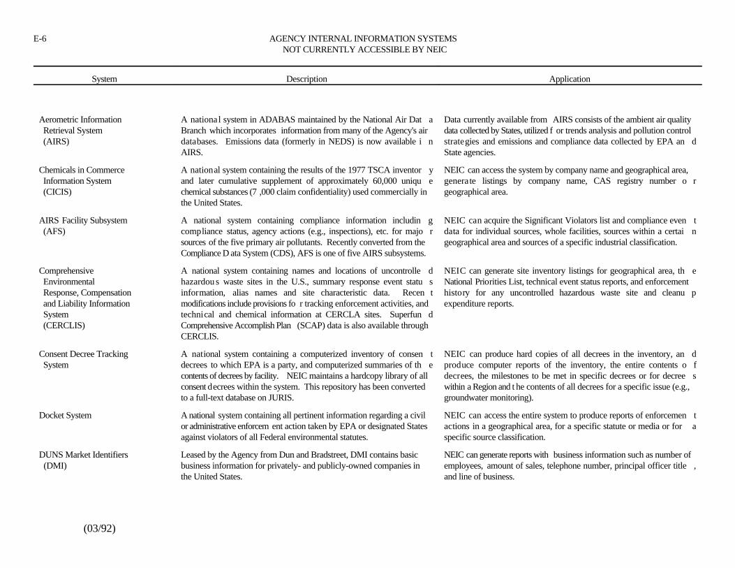
E-6 AGENCY INTERNAL INFORMATION SYSTEMS NOT CURRENTLY ACCESSIBLE BY NEIC
System Description Application
(03/92)
Aerometric Information A national system in ADABAS maintained by the National Air Dat a Data currently available from AIRS consists of the ambient air quality Retrieval System Branch which incorporates information from many of the Agency's air data collected by States, utilized f or trends analysis and pollution control (AIRS) databases. Emissions data (formerly in NEDS) is now available i n strategies and emissions and compliance data collected by EPA an d
AIRS. State agencies.
Chemicals in Commerce A national system containing the results of the 1977 TSCA inventor y NEIC can access the system by company name and geographical area, Information System and later cumulative supplement of approximately 60,000 uniqu e generate listings by company name, CAS registry number o r (CICIS) chemical substances (7 ,000 claim confidentiality) used commercially in geographical area.
the United States.
AIRS Facility Subsystem A national system containing compliance information includin g NEIC can acquire the Significant Violators list and compliance even t (AFS) compliance status, agency actions (e.g., inspections), etc. for majo r data for individual sources, whole facilities, sources within a certai n
sources of the five primary air pollutants. Recently converted from the geographical area and sources of a specific industrial classification.Compliance D ata System (CDS), AFS is one of five AIRS subsystems.
Comprehensive A national system containing names and locations of uncontrolle d NEIC can generate site inventory listings for geographical area, th e Environmental hazardou s waste sites in the U.S., summary response event statu s National Priorities List, technical event status reports, and enforcement Response, Compensation information, alias names and site characteristic data. Recen t history for any uncontrolled hazardous waste site and cleanu p and Liability Information modifications include provisions fo r tracking enforcement activities, and expenditure reports. System technical and chemical information at CERCLA sites. Superfun d (CERCLIS) Comprehensive Accomplish Plan (SCAP) data is also available through
CERCLIS.
Consent Decree Tracking A national system containing a computerized inventory of consen t NEIC can produce hard copies of all decrees in the inventory, an d System decrees to which EPA is a party, and computerized summaries of th e produce computer reports of the inventory, the entire contents o f
contents of decrees by facility. NEIC maintains a hardcopy library of all decrees, the milestones to be met in specific decrees or for decree sconsent decrees within the system. This repository has been converted within a Region and t he contents of all decrees for a specific issue (e.g.,to a full-text database on JURIS. groundwater monitoring).
Docket System A national system containing all pertinent information regarding a civil NEIC can access the entire system to produce reports of enforcemen tor administrative enforcem ent action taken by EPA or designated States actions in a geographical area, for a specific statute or media or for aagainst violators of all Federal environmental statutes. specific source classification.
DUNS Market Identifiers Leased by the Agency from Dun and Bradstreet, DMI contains basic NEIC can generate reports with business information such as number of (DMI) business information for privately- and publicly-owned companies in employees, amount of sales, telephone number, principal officer title ,
the United States. and line of business.
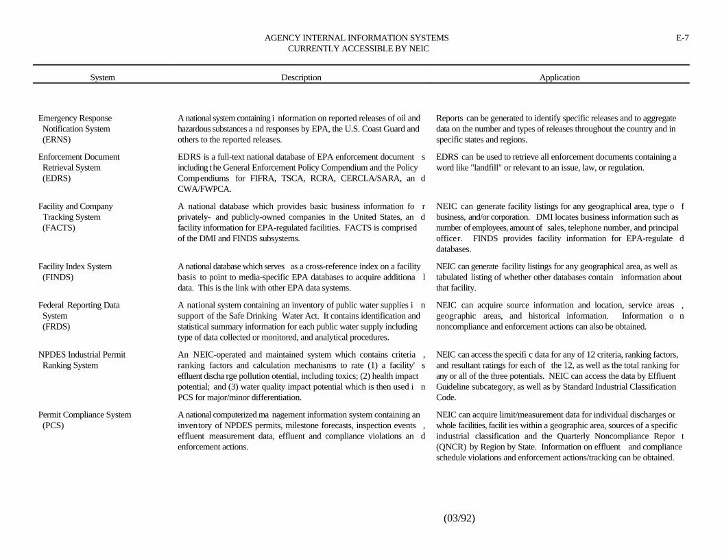
AGENCY INTERNAL INFORMATION SYSTEMS E-7CURRENTLY ACCESSIBLE BY NEIC
System Description Application
(03/92)
Emergency Response A national system containing i nformation on reported releases of oil and Reports can be generated to identify specific releases and to aggregate Notification System hazardous substances a nd responses by EPA, the U.S. Coast Guard and data on the number and types of releases throughout the country and in (ERNS) others to the reported releases. specific states and regions.
Enforcement Document EDRS is a full-text national database of EPA enforcement document s EDRS can be used to retrieve all enforcement documents containing a Retrieval System including the General Enforcement Policy Compendium and the Policy word like "landfill" or relevant to an issue, law, or regulation. (EDRS) Compendiums for FIFRA, TSCA, RCRA, CERCLA/SARA, an d
CWA/FWPCA.
Facility and Company A national database which provides basic business information fo r NEIC can generate facility listings for any geographical area, type o f Tracking System privately- and publicly-owned companies in the United States, an d business, and/or corporation. DMI locates business information such as (FACTS) facility information for EPA-regulated facilities. FACTS is comprised number of employees, amount of sales, telephone number, and principal
of the DMI and FINDS subsystems. officer. FINDS provides facility information for EPA-regulate ddatabases.
Facility Index System A national database which serves as a cross-reference index on a facility NEIC can generate facility listings for any geographical area, as well as (FINDS) basis to point to media-specific EPA databases to acquire additiona l tabulated listing of whether other databases contain information about
data. This is the link with other EPA data systems. that facility.
Federal Reporting Data A national system containing an inventory of public water supplies i n NEIC can acquire source information and location, service areas , System support of the Safe Drinking Water Act. It contains identification and geographic areas, and historical information. Information o n (FRDS) statistical summary information for each public water supply including noncompliance and enforcement actions can also be obtained.
type of data collected or monitored, and analytical procedures.
NPDES Industrial Permit An NEIC-operated and maintained system which contains criteria , NEIC can access the specifi c data for any of 12 criteria, ranking factors, Ranking System ranking factors and calculation mechanisms to rate (1) a facility' s and resultant ratings for each of the 12, as well as the total ranking for
effluent discha rge pollution otential, including toxics; (2) health impact any or all of the three potentials. NEIC can access the data by Effluentpotential; and (3) water quality impact potential which is then used i n Guideline subcategory, as well as by Standard Industrial ClassificationPCS for major/minor differentiation. Code.
Permit Compliance System A national computerized ma nagement information system containing an NEIC can acquire limit/measurement data for individual discharges or (PCS) inventory of NPDES permits, milestone forecasts, inspection events , whole facilities, facilit ies within a geographic area, sources of a specific
effluent measurement data, effluent and compliance violations an d industrial classification and the Quarterly Noncompliance Repor tenforcement actions. (QNCR) by Region by State. Information on effluent and compliance
schedule violations and enforcement actions/tracking can be obtained.
E-8 AGENCY INTERNAL INFORMATION SYSTEMS NOT CURRENTLY ACCESSIBLE BY NEIC
System Description Application
(03/92)
Pollution Prevention A national computerized information network providing access t o NEIC can use the system to stay ab reast of policy and program activities Information Exchange technical, programmetric, and legislative pollution preventio n at HQ and the regions as we ll as industry specific technical information. System informati on. Includes a calendar of events, case studies, directory o f Case studies of enforcement settlements incorporating pollutio n (PIES) contacts, an interactive message center, and document orderin g prevention projects can be obtained.
capability.
Potentially Responsible An NEIC-automated system, which links PRPs from SETS, SFFAS, and This system is used as an inventory of specific generators or paren t Parties System Techlaw files. corporations identified at and among hazardous waste sites.
Records of Decision System A full-text national database of over 2,000 Superfund Records o f NEIC can retrieve a specific ROD by searching onsite name or I D (RODS) Decision number or can identify all RODS having selected media, contaminants,
or remedies.
Resource Conservation and Conversion to RCRIS from HWDMS is currently underway on a pe r NEIC is planning to use the RCRIS Natio nal Oversight Database, which Recovery Information state basis. RCRIS is scheduled to be operating as the officia l is derived from the 10 regional RCR IS databases. Information available System (RCRIS) automated source of information on RCRA program activities b y will include handler identification, permitting/closure/post-closure ,
January 1992. compliance monitoring and enforcement, and corrective action an dprogram management data.
Site Enforcement Tracking A centralized national database tracking notice letters which have been NEIC uses this database to supplement currently available responsible System (SETS) sent to potentially responsible parties. party information.
STORET A national database containing water quality data for some 1,800 unique NEIC can access and produce reports of water quality, includin gparameters from over 200,000 collection points including lakes , groundwater quality, for specific geographical areas, for specifi cstreams, wells, and other waterways. New STORET software provides parameters (e.g., organics), and for a specific station.an interface between STORET and PCS data.
Superfund Financial Nationally available computer application designed to calculate th e NEIC has used the SFFAS too provide financial assessments fo r Assessment System remedial costs a responsible party can theoretically afford to pay fo r potentially responsible parties in response to HQ/Regional requests for (SFFAS) cleanup of a site. Three common financial ratios are used to make this several sites including the following: Seymour Recycling (severa l
determination: (1) Cash flow to total debt, (2) total debt to equity, and hundred responsible parties), Re-Solve (more than 200 responsibl e(3) the interest coverage ratio. parties), and MIDCO I and II (approximately 100 responsible parties).
AGENCY INTERNAL INFORMATION SYSTEMS E-9CURRENTLY ACCESSIBLE BY NEIC
System Description Application
(03/92)
TECHLAW Evidence Audit Under contract to NEIC, TECHLAW provides document inventories , NEIC can access the document inventories to substantiate the universe System evidence profiles and generator transaction databases. TECHLAW has of information on which a case is based, to demonstrate the efficacy and
produced, for about 30 cases, document inventories containing key word utility of an evidence audit system in enforcement case preparation andsearching capability of all related records contained in Regional office, to provide demonstrative examples of actual applications to establis hHeadquarters, Department of Justice and/or office files. For sampl e protocols and implementation procedures.related activities, including those of the contractor laboratories ,TECHLAW produces sample tracking profiles. For hazardous wast esites, TECHLAW has produced document inventories of availabl erecords dealing with the generators, volume and type of water, etc.
Toxic Release Inventory A national databas e containing information directly related to the Toxic NEIC can generate reports for facilities, geographic areas, and chemical System (TRIS) Chemical Release Inventory Report Form "R." Two types o f compounds listing facility and chemical information with emissions ,
submissions will be p resent: Partial (facility and chemical information) releases, activities, etc., for complete submissions.and Complete (offsit e transfers, emission and releases, waste treatment,waste minimization, activities and uses, and maximum amount store donsite).
E-10 AGENCY INTERNAL INFORMATION SYSTEMS NOT CURRENTLY ACCESSIBLE BY NEIC
System Description Application
(03/92)
FIFRA/TSCA Tracking System A PC-based regional system that tracks FIFRA and TSCA NEIC has limited access through Headquarters. The national(FTTS) inspections, samples, case reviews, enfrocement actions, referrals, database is used to produce facility listings showing inspections,
and State grants. A national database is planned for FY89. enforcement data, and product lists.
PUBLICLY EXTERNAL INFORMATION SYSTEMS E-11CURRENTLY ACCESSIBLE BY NEIC
System Description Application
(03/92)
Bibliographic Retrieval The BRS syste m contains more than 100 databases with unique files in BRS is used mainly as a backup when the DIALOG system i s System (BRS) the chemical technology and standards and specification areas. unavailable but is also used to obtain chemical manufacturing an d
production information for specific compounds.
Chemical Information The CIS is a collectio n of scientific and regulatory databases containing NEIC uses the CIS to locate mass spectral information environmenta l System (CIS) numeric, textual and some bibliographic information in the areas o f fate information, formulation ingredients for commercially availabl e
toxicology, environment, regulations, spectroscopy, and chemical an d products such as pesticides and waste disposal methods for hazardousphysical properties. substances.
Colorado Alliance of The CARL system includes the catalogs of the member libraries, a n CARL is searched by NEIC staff for general reference, to locate books, Research Libraries index of ove r 10,000 periodicals, a full text encyclopedia, Choice book and to identify articles and documents. (CARL) reviews, and a bibliography of GPO publications.
DataTimes DataTimes provides online access to numerous full-text databases , DataTimes is a source of national environmental news. Newspape rincluding newspapers, wire services, and Dow Jones News/Retrieval. databases from all regions are updated daily.
DIALOG Information The DIALOG system contains more than 330 databases covering a NEIC uses the DIALOG databases to obtain: (1) expert witnes s Services, Inc. variety of disciplines: Science, t echnology, engineering, social sciences, information, including biographies, pu blications authored, congressional
business, and economics. The databases contain more tha n testimony; (2) up-to-date pollution control technology for hazardou s120,000,000 records and are regularly updated to provide the mos t waste, air and water; and (3) business information such as corporat erecent information. officers, subsidiaries, and line of business.
Dun and Bradstreet Dun and Bradstreet, a credit-reporting firm, provides busines s NEIC uses the Dun and Bradstreet system to locate corporat einformation reports for privately- and publicly-owned companies an d information such as business done by the company, company history ,government activity reports which list Federal contracts, grants, fines, financial condition, subsidiaries, and corpo rate officers for privately-heldand debarments for specific companies. companies.
Groundwater On-Line The National Groundwater Information Center Database is a NEIC accesses GWOL to locate public ations on groundwater topics and (GWOL) bibliographic database containing references to materials o n to verify or locate groundwater experts.
hydrogeology and water well technology with emphasis on reports o rprojects sponsored by EPA.
E-12 PUBLICLY EXTERNAL INFORMATION SYSTEMS CURRENTLY ACCESSIBLE BY NEIC
System Description Application
(03/92)
Justice Retrieval and Inquiry The Justice Retrieval and Inq uiry System (JURIS) is a legal information JURIS is used to identify relevant caselaw and current statutory an d System (JURIS) system developed by the Department of Jus tice. It contains the complete regulatory environmental information.
text of Federal cases, statutes, and regulations in addition to selecte dDOJ Appella te Court Briefs, trial briefs, and the full text of the U.S .Attorneys' Manual. The full-text of the NE IC Consent Decree repositoryhas been added to JURIS. JURIS also contains comuterized legislativehistories of the environment al statutes, model pleadings, and other workproducts of DOJ attorneys, and EPA General Counsel opinions fro m1970 to the present.
NEXIS/LEXIS NEXIS/LEXIS contains the full text of more than 600 business an d NEIC uses NEXIS/LEXIS to keep informed of the latest Agency an dgeneral news files, including the Washingt on Post and New York Times. environmental news stories and to track corporate and financial statusStatutory and case law are provided for computer-aided legal research. of U.S. businesses involved in environmental litigation.
National Library of The National Library of Medicine system contains more than NEIC uses the NLM system to obtain: (1) toxicity and environmental Medicine (NLM) 5,000,000 references to journal articles and books in the health health effects information for individual chemicals or groups of
sciences published since 1965. chemicals, (2) physical and chemical properties of specificcompounds, (3) analytical methodology references, and (4) NationalCancer Institute carcinogenic bioassay information.
Scientific and Technical The STN system contains databases covering chemistry, science, an d NEIC uses the STN databases to obtain: (1) chemical structures an d Information Network engineering that are regularly updated to provide the most recen t synonyms for a chemical compound, (2) analytical methods an d (STN) information. STN has strong coverage of European and Japanes e techniques, and (3) toxicity of a chemical compound.
scientific databases.
NEIC can acquire source information and location, service areas,geographic areas, and historical information. Information onnoncompliance and enforcement actions can also be obtained.
VU/TEXT VU/TEXT contains the full text of 30 daily newspapers, includin g NEIC uses VU/TEXT to keep informed of the latest Agency an dnationally recognized papers such as the Boston Globe, Chicag o environmental news stories and to track corporate and financial statusTribune, Det roit Free Press, Philadelphia Inquirer, and regional papers of U.S. businesses involved in environmental litigation.such as the Orlando Sentinel, the Sacramento Bee and the San Jos eMercury News.
PUBLICLY EXTERNAL INFORMATION SYSTEMS E-13CURRENTLY ACCESSIBLE BY NEIC
System Description Application
(03/92)
WESTLAW The WESTLAW system contains legal information, including the full NEIC uses WESTLAW toidentify precedent cases, to locate all casestext of cases from the Supreme Court, U.S. Court of Appeals, U.S. decided by a certain judge or all cases represented by a certainDistrict Courts, and State Courts. It contains Shepards' Citations, attorney and to locate possible expert witnesses.regulatory information froom the Code of Federal Regulations,Federal Register, U.S. Code and the expert witness information fromForensic Services Directory.
F-1
Subject to revision*
(03/92)
PROJECT PLAN *******
MULTI-MEDIA COMPLIANCE INVESTIGATIONXYZ COMPANY, MIDTOWN, ANYSTATE
INTRODUCTION
The XYZ Company operates a plant at 1234 An ywhere Road in the middle part of Midtown,Anystate [Figure 1]. EPA Region XX requested that NEIC conduct a multi-media complianc einvestigation of the XYZ plant. The specific objectives of the investigation are to determin ecompliance with:
Water pollution control regulations under the Clean Water Act (CWA), includin gwastewater pretreatment requirements and Spill Prevention and Contro lCountermeasures (SPCC) regulations
Hazardous waste management regulations, under the Resource Conservation an dRecovery Act (RCRA) and the Anystate Administrative Code (AAC)
Underground Storage Tank (UST) regulations
Air pollution control regulations under the Clean Air Act (CAA), Federa lImplementation Plan (FIP), and the Federally approved portions of the Stat eImplementation Plan (SIP)
Toxic Substances Control Act (TSCA) PCB regulations
Superfund Amendments Reauthorization Act, Title III, Emergency Planning an dCommunity Right-To-Know Act (EPCRA) regulations
Compliance with other applicable environmental regulat ions may be determined by the NEIC.Region XX personnel will evaluate compliance with TSCA Sections 5, 8, 1 2, and 13 during the NEICinspection, and report their findings separately.
BACKGROUND
XYZ began operating the plant in 1492. Compounds A, B, and C; chemicals D, E, and F ;pesticides G and H, and special containers for these materials have been manufactured on site. I n1942, some operations (formerl y under the Middle Division) were acquired by a company known as"Newage, Inc." The remaining XYZ plan t currently manufactures water soluble specialty items, andconducts research and development.
The XYZ plant employs a total of about 1,300 people, in a Primary Division, a Secondar yDivision, a Tertiary Division, and R and D Laboratory. The Primary Division manufacture scompounds A, B , and C (240 tons in 1990). Raw materials for the compounds are purchased from
F-2
(03/92)
an outside source. The Secondary Division makes chemicals and pesticides under numerous brandnames (180 tons in 1990), and the Tertiary Division makes special containers for these materials (3million containers in 1990). Research and development are conducted by R and D Laboratory.
The EPA Region XX Environmental C ompliance Division, Midtown District Office (MDO),conducted a multi-media inspection of the XYZ plant during the first quarter of 1991. The MD Oinspection report identified concerns with wastewater control, hazardous waste management ,documentation, and spill prevention control.
Approximately 1.2 million gallons of wastewater per day are discharged to the Midtow nWastewater Treatment Plant (MWTP) of Midtown, Anystate. There are two direct Nationa lPollutant Discharge Elimination System discharges (001 and 002) to the Midtown River at thi sfacility. Additionally, sewered plant effluent discharge is regulated by the MWTP pretreatmen tstandards, and the Federal effluent limitations and standards for the Compounds, Chemicals ,Pesticides and Containers point source category. The R and D Laboratory conducts the Company'seffluent analyses.
Violations of the MWTP pretreatment ordinance effluen t limitations have occurred for solids,and the toxic standards. MWTP is concerned with data indicating the discharge of solids and toxicsJ, K, and L from the plant . XYZ also may have modified their pretreatment plant without obtaininga construction permit required by the Anystate Environmental Resources Department (AERD).
XYZ submitted the original RCRA Part A permit application on November 15, 1980. Theapplication listed 19 hazardous waste management units, including 4 container storage areas, 1 0storage tanks, and 5 storage surface impoundments. AERD is responsible for monitoring hazardouswaste activities.
The facility's June 1990 contingency plan lists 1 4 above ground and 22 underground tanks onsite. The tanks range in size from 2,000 to 50,000 gallons, with the majority between 5,000 an d20,000 gallons. These tanks are located in a tank farm area and near production areas.
The plant emits both volatile organics and particulates. There is no volatile organi cconstituent emission control equipment. Particulate emissi ons are controlled by three dust collectors.Five wet scrubbers are used to control fugitive particulate emissions when mixing bags of dry rawmaterials in reaction vessels. Air emissions are regulated by "Anystate Permits and Air Pollutio nregulations including AERD Operating Permits. EP A also promulgated a FIP on February 14, 1991.
On August 31, 1983, EPA Region XX conducted a PCB sampling inspection at the plant .XYZ was fined for viol ations, including cracks in the floor of the PCB storage area, not conductingmonthly inspections, no annual document, and not properly marking PCB transformers.
The Toxic Release Inventory (TRI) for this plant lists emissions of A, B, C, and D. The TRIalso lists various inorganics, including E, F, G, and H.
INVESTIGATIVE METHODS
Investigation objectives will be addressed by:
F-3
NEIC Policies and Procedures Manual, revised August 1991*
(03/92)
Compilation and review of EPA, AERD, and MWTP database and file information
Meetings with EPA Region XX personnel to discu ss investigation specifics including:objectives, logistics, and potential sampling locations
An on-site inspection
Meetings with Region XX personnel took place (date). The on-site inspection, scheduled tobegin (date), will include:
Discussing plant operations with facility personnel
Reviewing and copying, as appropriate, facility documents including operating plansand records
Visually inspecting plant facilities including processing, material storage, and wastehandling facilities
Sampling and analysis of appropriate waste streams and/or any un known/unauthorizeddischarges to assist in compliance determination, as follows:
(a) MWTP will col lect and analyze wastewater samples for organic constituentsduring the week of (date). All QA/QC will be the responsibility of MWTP.
(b) NEIC will collect wastewater samples for v olatile organic constituent analysisduring the on-site inspection. NEIC will conduct the associated analysis.
After completing the on-site inspection, NEIC investigators will br ief appropriate EPARegion XX Program and Office of Regional Counsel per-sonnel regarding preliminar yfindings.
A draft report, including any analytical data, will be written by NEIC personnel andtransmitted to EPA Region XX personnel for review and comment. A final report will becompleted about two weeks after Region V comments are received. If analytical data are notavailable by (date), they will be presented in an addendum to the report.
NEIC personnel will be available for any additional support required (negotiations ,litigation, etc.) until noncompliance issues are resolved.
DOCUMENT CONTROL PROCEDURES
NEIC document control procedures will be followed during the inv estigation. TSCA**
"Notice of Inspection" and "Confidentiality" forms will be completed during the openin gconference. Documents and r ecords obtained from the Company will be uniquely numbered
F-4
(03/92)
and listed on docu-ment logs. Photograph logs will also be maintained. A copy of th edocument and photograph logs, w ith a Receipt For Samples/Document form, will be offeredto the Company prior to completion of the on-site inspection. Any documents declared tobe confidential business information pursuant to 40 CFR Part 2 will be so noted on the logand secured appropriately.
SAFETY PROCEDURES
Safety procedures to be followed during the on- site inspection will comply with thosedescribed in the attached safety p lan [Appendix A], and established NEIC safety procedures.These procedures are contained in EPA 1440 - Occupational Healt h and Safety Manual (1986edition), Agency orders and applicable provisions of the NIOS H/OSHA/USCG/EPA Occupa-tional Safety and Health Guidance Manual for Hazardous Waste Site Activities. Th eCompany's safety policies will also be reviewed and followed.
TENTATIVE SCHEDULE
(date) Region XX will notify facility of inspection (verbally and in writing)(date) Initiate on-site inspection(date) Brief Region V regarding preliminary findings(date) Draft report to Region V
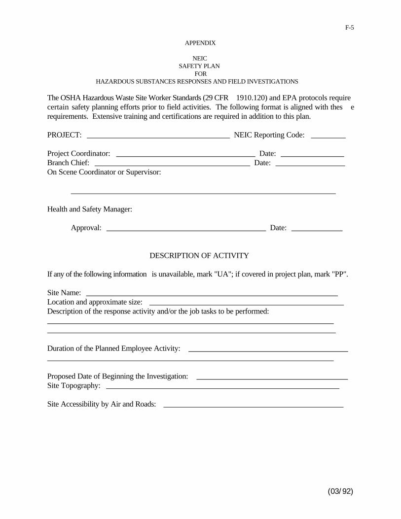
(03/92)
F-5
APPENDIX
NEIC SAFETY PLAN
FORHAZARDOUS SUBSTANCES RESPONSES AND FIELD INVESTIGATIONS
The OSHA Hazardous Waste Site Worker Standards (29 CFR 1910.120) and EPA protocols requirecertain safety planning efforts prior to field activities. The following format is aligned with thes erequirements. Extensive training and certifications are required in addition to this plan.
PROJECT: NEIC Reporting Code:
Project Coordinator: Date: Branch Chief: Date: On Scene Coordinator or Supervisor:
Health and Safety Manager:
Approval: Date:
DESCRIPTION OF ACTIVITY
If any of the following information is unavailable, mark "UA"; if covered in project plan, mark "PP".
Site Name: Location and approximate size: Description of the response activity and/or the job tasks to be performed:
Duration of the Planned Employee Activity:
Proposed Date of Beginning the Investigation: Site Topography:
Site Accessibility by Air and Roads:
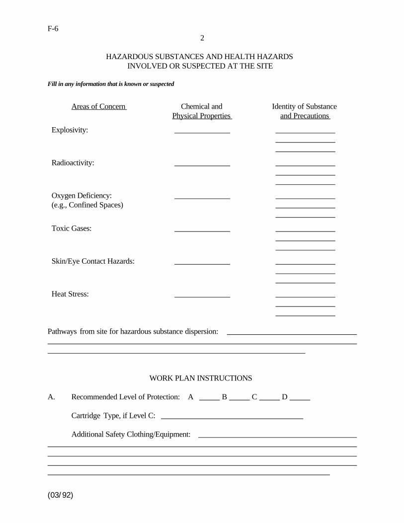
(03/92)
F-62
HAZARDOUS SUBSTANCES AND HEALTH HAZARDSINVOLVED OR SUSPECTED AT THE SITE
Fill in any information that is known or suspected
Areas of Concern Chemical and Identity of SubstancePhysical Properties and Precautions
Explosivity:
Radioactivity:
Oxygen Deficiency: (e.g., Confined Spaces)
Toxic Gases:
Skin/Eye Contact Hazards:
Heat Stress:
Pathways from site for hazardous substance dispersion:
WORK PLAN INSTRUCTIONS
A. Recommended Level of Protection: A B C D
Cartridge Type, if Level C:
Additional Safety Clothing/Equipment:
(03/92)
F-73
Monitoring Equipment to be Used:
CONTRACTOR PERSONNEL:
Number and Skills
CONTRACTOR SAFETY CLOTHING/EQUIPMENT REQUIRED: Have contractors received OSHA required training and certification? (29 CFR 1910.120)
Yes Not Required
(If "yes", copy of training certificate(s) must be obtained from contractor)
B. Field Investigation and Decontamination Procedures:
Decontamination Procedures (contaminated protective clothing, instruments, equipment, etc.):
Disposal Procedures (contaminated equipment, supplies, disposal items, washwater, etc.):
(03/92)
F-84
IV. EMERGENCY CONTACTS
Hospital Phone No.:
Hospital Location: EMT/Ambulance Phone No.: Fire Assistance Phone No.:
NEIC Health and Safety Manager: Steve Fletcher - 303/236-5111 FTS 776-5111
Radiation Assistance: Wayne Bliss, Director Office of Radiation Programs Las Vegas Facility (ORP-LVF) 702/798-2476 FTS 545-2476
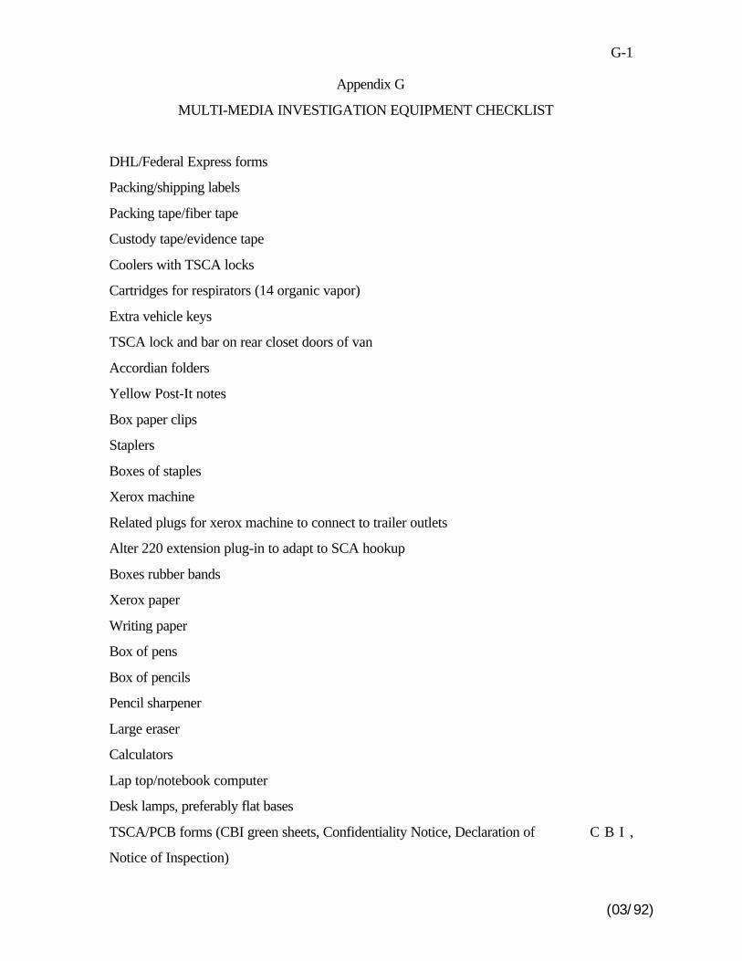
G-1
(03/92)
Appendix G
MULTI-MEDIA INVESTIGATION EQUIPMENT CHECKLIST
DHL/Federal Express forms
Packing/shipping labels
Packing tape/fiber tape
Custody tape/evidence tape
Coolers with TSCA locks
Cartridges for respirators (14 organic vapor)
Extra vehicle keys
TSCA lock and bar on rear closet doors of van
Accordian folders
Yellow Post-It notes
Box paper clips
Staplers
Boxes of staples
Xerox machine
Related plugs for xerox machine to connect to trailer outlets
Alter 220 extension plug-in to adapt to SCA hookup
Boxes rubber bands
Xerox paper
Writing paper
Box of pens
Box of pencils
Pencil sharpener
Large eraser
Calculators
Lap top/notebook computer
Desk lamps, preferably flat bases
TSCA/PCB forms (CBI green sheets, Confidentiality Notice, Declaration of C B I ,
Notice of Inspection)
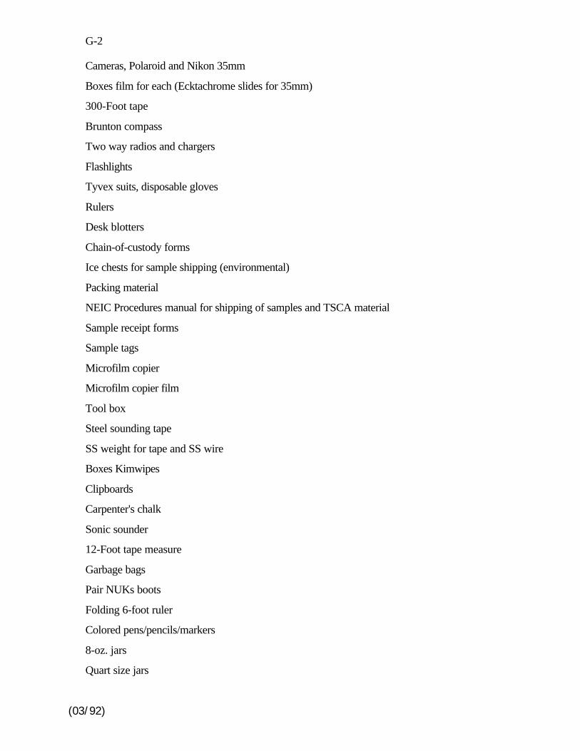
G-2
(03/92)
Cameras, Polaroid and Nikon 35mm
Boxes film for each (Ecktachrome slides for 35mm)
300-Foot tape
Brunton compass
Two way radios and chargers
Flashlights
Tyvex suits, disposable gloves
Rulers
Desk blotters
Chain-of-custody forms
Ice chests for sample shipping (environmental)
Packing material
NEIC Procedures manual for shipping of samples and TSCA material
Sample receipt forms
Sample tags
Microfilm copier
Microfilm copier film
Tool box
Steel sounding tape
SS weight for tape and SS wire
Boxes Kimwipes
Clipboards
Carpenter's chalk
Sonic sounder
12-Foot tape measure
Garbage bags
Pair NUKs boots
Folding 6-foot ruler
Colored pens/pencils/markers
8-oz. jars
Quart size jars

G-3
(03/92)
Plastic Ziplocks
Glass thieves
Plastic/metal scoops
Shovel
pH paper/meter
HNu meter
Bacon bombs
Sampling gear
Media-specific sampling gear
H-1
(03/92)
Appendix HSUGGESTED RECORDS/DOCUMENTS REQUEST
GENERAL PROCEDURE
The records evaluation generally will proce ed in two stages. First, variousrecords to be reviewed will be identified. Genera lly, these records will date back 3years fromthe present, but some of the records will be for specific time periods. Second, according toa schedule t o be developed onsite, the records will be reviewed and copies requested, a sneeded. Alternately, document copies will be requested for later review after th einvestigation.
GENERAL
1. Facility map and plot plan2. Organizational chart3. Description of facility and operations
CLEAN AIR ACT (CAA)
1. Plot plan of the facility showing location and identification of all majo rprocess area and stacks
2. Brief descriptions for all process areas to include:
(a) Simplified process flow diagrams(b) Pollution control equipment
3. Permits and/or variances for air emission sources and relate dcorrespondence
4. Consent Decrees/Orders/Agreements still in effect
5. Sulfur in fuel records for boiler/space heater fuel
6. Stack tests (most recent) and stack and ambient monitoring data (last 2quarters)
7. Performance specification tests for continuous emission monitors
8. 1989 state emissions inventory report
9. Procedures/manuals for the operation and inspection of pollution controlequipment
10. Required notices for asbestos demolition/renovation projects in progressor completed within the last three years
H-2
(03/92)
11. Hours of operation and process weight rates for the automated multi-basepropellant (AMB) manufacturing facility (last 2 years)
12. Annual volatile organic compounds (VOC) emissions from the AM Bfacility including associated VOC storage tanks (last 2 years). Describ ethe method(s) used to determine emissions. If estimates have been madeshow calculations and assumptions.
13. Annual AMB facility inspections reports (last 2 years)
14. Annual AMB facility VOC emissions control reports (last 5 years)
15. Non-compliance AMB reports (last 2 years)
16. List air pollution source s, not covered in items 1 - 8, such as combustionsunits larger than 2.5 million BTUs/hr heat inputs and incinerators (othe rthan the RCRA incinerators)
RESOURCE CONSERVATION AND RECOVERY ACT (RCRA)
1. List of description of all hazardous waste storage areas, including aboveand below ground tanks, temporary tanks, drum sto rage areas, pits, ponds,lagoons, waste piles, etc., that have been operated at any time sinc eNovember 1980.
2. RCRA Part A Permit Application
3. Manifests for all offsite shipments of hazardous waste, includin gnotifications and certifications for Land Disposal Restricted (LDR )hazardous waste.
4. Determinations, data, document s, etc., supporting the Base's decision thatwastes are hazardous, non-hazardous or LDR hazardous wastes for al lsolid wastes, as defined under RCRA. Also provide information used inthe determination of the EPA hazardous waste codes applied to al lhazardous wastes.
5. Notices to the owner or operator of the disposal facility receiving wast esubject to land disposal restrictions
6. Schedule and inspection logs for inspection of safety and emergenc yequipment, security devices, monitoring equipment, and operating an dstructural equipment
7. Satellite accumulation area inspection records
H-3
(03/92)
8. Employee training records for hazardous waste hand lers, including job titleand description, name of each employee and documentation of the typ eand amount of training each has received.
9. Current Contingency Plan
10. Current Closure Plan
11. Copy of the Waste Analysis Plan (WAP) currently in u se and effective dateof the plan. If the current WAP was not effective on January 1, 198 6provide copies of all WAPs and revisions.
12. Narrative of procedures u sed to store hazardous wastes prior to shipmentoffsite for treatment, recycle, reclamation and/or disposal. Include a listof all storage and satellite storage areas and the quantity of waste storedat each area.
13. Summary reports and documentation of all incidents that require dimplementation of the contingency plan for the past 3 years
14. The Generator Biennial and Exception Reports
15. Reports and analytical results of any groundwate r quality and groundwatercontamination surveys
16. Closure plan for units undergoing closure
17. Inspection schedule(s ) for all hazardous waste management units, such asstorage areas and tank systems, and all inspection logs, remediation sdocument, etc, for the last three years.
18. Description of the Facility’s hazardous waste minimization plan
19. Copy of the annual report for the last three years
20. Copy of notification to EPA of hazardous waste activity to secur egenerator ID number
21. Copy of Clean Closure Demonstration, if any.
22. List of all identified or suspected Solid Waste Management Units on theBase's property
23. List of all locations where hazardous wastes are generated including types,quantity, and EPA hazardous waste codes of wastes
24. Notification of any releases to the environment and follow-up reports
H-4
(03/92)
25. Notifications for underground storage tanks
26. Copy of written tank integrity assessment certified by a professiona lengineer
27. Agreements with local emergency response authorities or documentationof refusal by the emergency response authorities to enter into suc hagreements.
28. Design specifications for any underground storage tanks installed afte rMay 1985
29. Characteristics of materials removed from fac ility septic systems, includinganalytical results
30. Wastes burned in the RCRA incinerators, including waste analysis
31. Instruments used to monitor incinerator combustions and emissions
32. Incinerator inspection records (last year)
TOXIC SUBSTANCES CONTROL ACT - PCB WASTE MANAGEMENT
1. Copies of the "Annual Documen t" required by 40 CFR 761.180(a) for thelast 3 years
2. Records of monthly inspections of storage ar eas subject to 40 CFR 761.65
3. The SPCC plan prepared for storage areas subject to 40 CFR 761.65
4. All spill reports
5. Records of inspection and maintenance for PCB transformers for the last3 years
6. Transformer inventory and PCB analyses
7. Reports or other documentation identifying the extent of any PCB spill sand any remediation plans
8. Certifications of Destruction for PCB Transformer disposal
9. Manifests for PCB items shipped offsite
CLEAN WATER ACT (CWA)
1. All NPDES permit(s) applications
H-5
(03/92)
2. NPDES permit effective for last 3 years
3. Discharge monitoring reports (DMRs) for last 3 years
4. Any correspondence regarding exceedences of discharge limitations
5. Spill Prevention Control and Countermeasure (S PCC) plan and PreventionPreparedness and Contingency (PPC) plan
6. Description or lies of all sewer system monitoring stations and analyse sconducted on samples collected (include monitoring frequency).
7. Written calibration procedures for flow measuring and recordin gequipment; includes industrial sewers, storm sewers, sanitary sewers o rany other sewers on the Plant's property.
8. Description of waste water treatment pla nt, sewer system and storm waterby-pass system
9. Consent decrees/agreements still in effect
COMPREHENSIVE ENVIRONMENTAL RESPONSE COMPENSATIONAND LIABILITY ACT (CERCLA)
1. Specific CERCLA questions will be provided during the inspection.
EMERGENCY PLANNING COMMUNITY RIGHT-TO-KNOW ACT (EPCRA)
1. Notification to the State Emergency Response Commission
2. Designated facility emergency coordinator
3. Written follow-up emergency release notifications
4. Material Safety Data S heet report to the Commission and fire department
5. Tier I/Tier II submittal to the Commission and fire department
6. EPA Form R submittals for the past 3 years
7. Documentation supporting the Form R submittals for the past 3 years
FEDERAL INSECTICIDE, FUNGICIDE, AND RODENTICIDE ACT (FIFRA)
1. Restricted pesticide use and application records
2. Pesticide handlers training and certification records

H-6
(03/92)
3. Pesticide inventory and storage area inspection records
SAFE DRINKING WATER ACT
1. Description of water supply system including supply, storage capacity ,distribution, and monitoring system
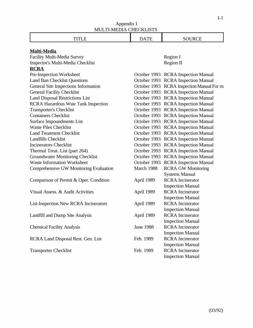
(03/92)
I-1Appendix I
MULTI-MEDIA CHECKLISTS
TITLE DATE SOURCE
Multi-MediaFacility Multi-Media Survey Region IInspector's Multi-Media Checklist Region IIRCRAPre-Inspection Worksheet October 1993 RCRA Inspection ManualLand Ban Checklist Questions October 1993 RCRA Inspection ManualGeneral Site Inspections Information October 1993 RCRA Inspection Manual For mGeneral Facility Checklist October 1993 RCRA Inspection ManualLand Disposal Restrictions List October 1993 RCRA Inspection ManualRCRA Hazardous Wste Tank Inspection October 1993 RCRA Inspection ManualTransporter's Checklist October 1993 RCRA Inspection ManualContainers Checklist October 1993 RCRA Inspection ManualSurface Impoundments List October 1993 RCRA Inspection ManualWaste Piles Checklist October 1993 RCRA Inspection ManualLand Treatment Checklist October 1993 RCRA Inspection ManualLandfills Checklist October 1993 RCRA Inspection ManualIncinerators Checklist October 1993 RCRA Inspection ManualThermal Treat. List (part 264) October 1993 RCRA Inspection ManualGroundwater Monitoring Checklist October 1993 RCRA Inspection ManualWaste Information Worksheet October 1993 RCRA Inspection ManualComprehensive GW Monitoring Evaluation March 1988 RCRA GW Monitoring
Systems ManualComparison of Permit & Oper. Condition April 1989 RCRA Incinerator
Inspection ManualVisual Assess. & Audit Activities April 1989 RCRA Incinerator
Inspection ManualList-Inspection New RCRA Incinerators April 1989 RCRA Incinerator
Inspection ManualLandfill and Dump Site Analysis April 1989 RCRA Incinerator
Inspection ManualChemical Facility Analysis June 1988 RCRA Incinerator
Inspection ManualRCRA Land Disposal Rest. Gen. List Feb. 1989 RCRA Incinerator
Inspection ManualTransporter Checklist Feb. 1989 RCRA Incinerator
Inspection Manual
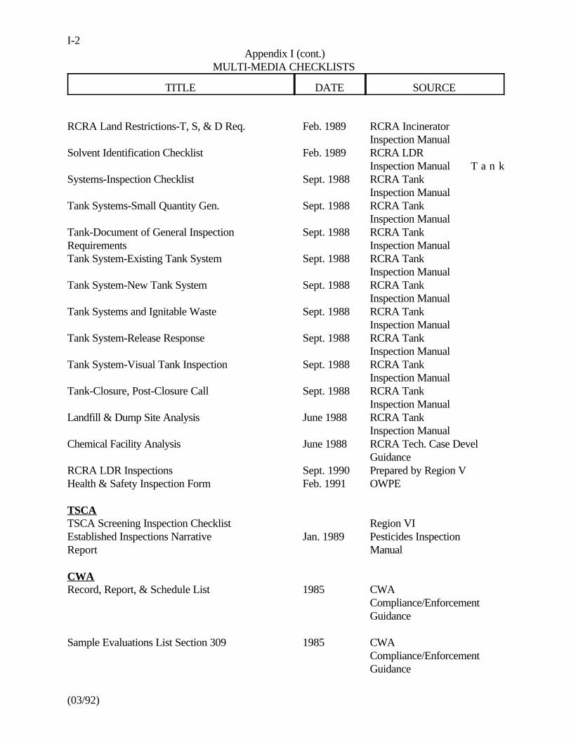
I-2Appendix I (cont.)
MULTI-MEDIA CHECKLISTS
TITLE DATE SOURCE
(03/92)
RCRA Land Restrictions-T, S, & D Req. Feb. 1989 RCRA IncineratorInspection Manual
Solvent Identification Checklist Feb. 1989 RCRA LDRInspection Manual T a n k
Systems-Inspection Checklist Sept. 1988 RCRA TankInspection Manual
Tank Systems-Small Quantity Gen. Sept. 1988 RCRA TankInspection Manual
Tank-Document of General Inspection Sept. 1988 RCRA TankRequirements Inspection ManualTank System-Existing Tank System Sept. 1988 RCRA Tank
Inspection ManualTank System-New Tank System Sept. 1988 RCRA Tank
Inspection ManualTank Systems and Ignitable Waste Sept. 1988 RCRA Tank
Inspection ManualTank System-Release Response Sept. 1988 RCRA Tank
Inspection ManualTank System-Visual Tank Inspection Sept. 1988 RCRA Tank
Inspection ManualTank-Closure, Post-Closure Call Sept. 1988 RCRA Tank
Inspection ManualLandfill & Dump Site Analysis June 1988 RCRA Tank
Inspection ManualChemical Facility Analysis June 1988 RCRA Tech. Case Devel
GuidanceRCRA LDR Inspections Sept. 1990 Prepared by Region VHealth & Safety Inspection Form Feb. 1991 OWPE
TSCATSCA Screening Inspection Checklist Region VIEstablished Inspections Narrative Jan. 1989 Pesticides InspectionReport Manual
CWARecord, Report, & Schedule List 1985 CWA
Compliance/EnforcementGuidance
Sample Evaluations List Section 309 1985 CWACompliance/EnforcementGuidance
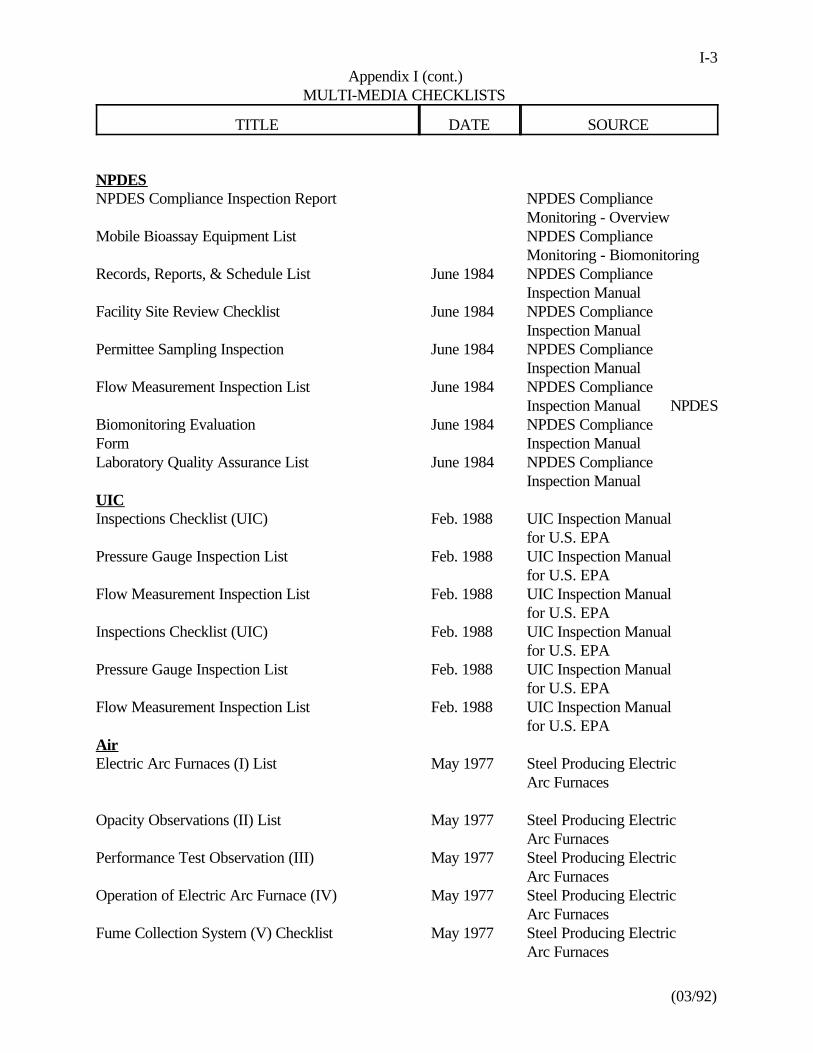
I-3Appendix I (cont.)
MULTI-MEDIA CHECKLISTS
TITLE DATE SOURCE
(03/92)
NPDESNPDES Compliance Inspection Report NPDES Compliance
Monitoring - OverviewMobile Bioassay Equipment List NPDES Compliance
Monitoring - BiomonitoringRecords, Reports, & Schedule List June 1984 NPDES Compliance
Inspection ManualFacility Site Review Checklist June 1984 NPDES Compliance
Inspection ManualPermittee Sampling Inspection June 1984 NPDES Compliance
Inspection ManualFlow Measurement Inspection List June 1984 NPDES Compliance
Inspection Manual NPDESBiomonitoring Evaluation June 1984 NPDES ComplianceForm Inspection ManualLaboratory Quality Assurance List June 1984 NPDES Compliance
Inspection ManualUICInspections Checklist (UIC) Feb. 1988 UIC Inspection Manual
for U.S. EPAPressure Gauge Inspection List Feb. 1988 UIC Inspection Manual
for U.S. EPAFlow Measurement Inspection List Feb. 1988 UIC Inspection Manual
for U.S. EPAInspections Checklist (UIC) Feb. 1988 UIC Inspection Manual
for U.S. EPAPressure Gauge Inspection List Feb. 1988 UIC Inspection Manual
for U.S. EPAFlow Measurement Inspection List Feb. 1988 UIC Inspection Manual
for U.S. EPAAirElectric Arc Furnaces (I) List May 1977 Steel Producing Electric
Arc Furnaces
Opacity Observations (II) List May 1977 Steel Producing ElectricArc Furnaces
Performance Test Observation (III) May 1977 Steel Producing ElectricArc Furnaces
Operation of Electric Arc Furnace (IV) May 1977 Steel Producing ElectricArc Furnaces
Fume Collection System (V) Checklist May 1977 Steel Producing ElectricArc Furnaces
I-4Appendix I (cont.)
MULTI-MEDIA CHECKLISTS
TITLE DATE SOURCE
(03/92)
Fabric Filter Collectors (VI) Checklist May 1977 Steel Producing ElectricArc Furnaces
Scrubbers (VI) Checklist May 1977 Steel Producing ElectricArc Furnaces
Electrostatic Precipitators (VIII) List May 1977 Steel Producing ElectricArc Furnaces
Tank Inspection Checklist April 1977 Volatile HydrocarbonStorage Tanks
Sewage Sludge Incinerators - During Feb. 1975 Sewage Sludge IncineratorsPerformance TestSewage Sludge Incinerators - After Feb. 1975 Sewage Sludge IncineratorsPerformance TestMunicipal Incinerators - During Feb. 1975 Municipal IncineratorsPerformance TestMunicipal Incinerators - After Feb. 1975 Municipal IncineratorsPerformance TestSecondary Brass & Bronze Smelters - Jan. 1977 Secondary Brass & BronzeDuring Performance Test Ingot Production PlantsSecondary Lead Smelters - During Jan. 1977 Secondary Lead SmeltersPerformance TestBasic Oxygen Process Furnace - Jan. 1977 Basic Oxygen ProcessDuring Performance Test FurnacesPerformance Test of Portland Cement Sept. 1975 Portland Cement PlantsPlantsPeriodic Check of Portland Cement Sept. 1975 Portland Cement PlantsPlantSteam-Electric Generators - During Feb. 1975 Fossil-Fuel Fired SteamPerformance Test GeneratorsSteam-Electric Generation - After Feb. 1975 Fossil-Fuel Fired SteamPerformance Test GeneratorsMunicipal Incinerators Checklist June 1973 Combustion & Incineration
Sources

APPENDIX I
MULTI-MEDIA CHECKLISTS
I-6Appendix I (cont.)
MULTI-MEDIA CHECKLISTS
TITLE DATE SOURCE
(03/92)
J-1
Table 1
INVESTIGATION AUTHORITY UNDER THE MAJOR ENVIRONMENTAL ACTS
CAA - § 114(a)(2)". . .the Administrator or hi s authorized representative, upon presentation of his credentials - shall havea right of entry to, upon, or through any pre mises of such person or in which any records required to bemaintained. . .are located, and may at reasonable ti mes have access to and copy any records, inspect anymonitoring equipment and method. . .and sample any emissions. . .."
CWA - § 308(a)(4)(B)
". . .the Administrato r or his authorized representative. . .upon presentation of his credentials - (i) shallhave a right of entry to, upon, or through any premises in w hich an effluent source is located or in whichany records required to be maintained. . .are located, and (ii) may at reasonable times have access to andcopy any records, inspect any monitoring equipment or method. . .any sample any effluents which theowner or operator of such source is required to sample. . .."
RCRA - § 3007(a)
". . .any such person who generates, stores, treats, transports, disposes of or otherwise handles or hashandled hazardous wastes shall upon request of any. . .employee or representative of the EnvironmentalProtection Agency. . .furnish information relating to such wastes and permit such person at all reasonabletimes to have access to, and to copy all records relating to such wastes."
". . .such employees or representatives are authorized. . .to enter at reasonable times any establishmentor other place where hazardous wastes are or have been generated, stored, treated, or disposed of ortransported from; to inspect and obtain sam ples from any person of any such wastes and samples of anycontainers or labeling for such wastes."
- § 9005(a)(1)
". . .representatives are authorized. . .to enter. . .inspect and obtain samples. . .
TSCA - § 11(a)(b)
". . .any duly designated re presentative of the Administrator, may inspect any establishment. . .in whichchemical substances or mixtures are manufactured, processed, stored, or held before or after thei rdistribution in commerce and any conveya nce being used to transport chemical substances, mixtures, orsuch articles in connection with distribution in commerce. Such an inspection may only be made upon
I-7Appendix I (cont.)
MULTI-MEDIA CHECKLISTS
TITLE DATE SOURCE
(03/92)
the presentation of appropriate credentials and of a written notice to the owner, co-operator, or agentin charge of the premises or conveyance to be inspected."
FIFRA - § 8 and 9
". . .any person who sells or offers for sale, delivers, or offers for delivery any pesticide. . .shall, uponrequest of any officer or employee of the Environmental Protection Agency. . .furnish or permit suchperson at all reasonable times to have access to, and to copy: (1) all records showing the delivery ,movement, or holding of such pesticide or device, including the quantity, the date of shipment an dreceipt, and the name of the consignor and consignee. . .."
". . .officers or employees duly designated by the Administrator are authorized to enter at reasonabl etimes, any establishment or other place where pesticides or devices are held for distribution or sale forthe purpose o f inspecting and obtaining samples of any pesticides or devices, packaged, labeled, an dreleased for shipment and samples of any containers or labeling for such pesticides or devices."
"Before undertaking such inspecti on, the officers or employees must present to the owner, operator, oragent in charge of t he establishment. . .appropriate credentials and a written statement as to the reasonfor the inspection, including a statement as to whether a violation of the law is suspected."
". . .employees duly designated by the Administrato r are empowered to obtain and too execute warrantsauthorizing entry. . .inspection and reproduction of all records. . .and the seizure of any pesticide o rdevice which is in violation of this Act."
SDWA - § 1445
". . .the Administrator, or representatives of the Administrator. . .u pon presenting appropriate credentialsand a written n otice to any. . .person subject to. . .any requirement. . .is authorized to enter an yestablishment, facility, or other pro perty. . .in order to determine. . .compliance with this title, includingfor this purpose, inspection, at reasonable times, of records, files, papers, processes, controls, an dfacilities or in order to test any feature of a public water system, including its raw water source."
CERCLA (Superfund) - § 104(e)
"Any officer, employee, or representative of the President. . .is authorized to . . .
require any person.. .to furnish. . .information or documents relating to. . .identification, nature, an dquantity of material. . .generated, treated, stored, or disposed. . .or transported. . .nature or extent ofa release. . .ability of a person to pay. . ."
". . .access. . .to inspect and copy all documents or records. . ."
I-8Appendix I (cont.)
MULTI-MEDIA CHECKLISTS
TITLE DATE SOURCE
(03/92)
". . .to enter. . .place or property wh ere any hazardous substance or pollutant or contaminant may be orhas been generated, stored, treated, disposed of, or transported from. . .needed to determine the needfor response. . ."
". . .to inspect and obtain samples. . ."
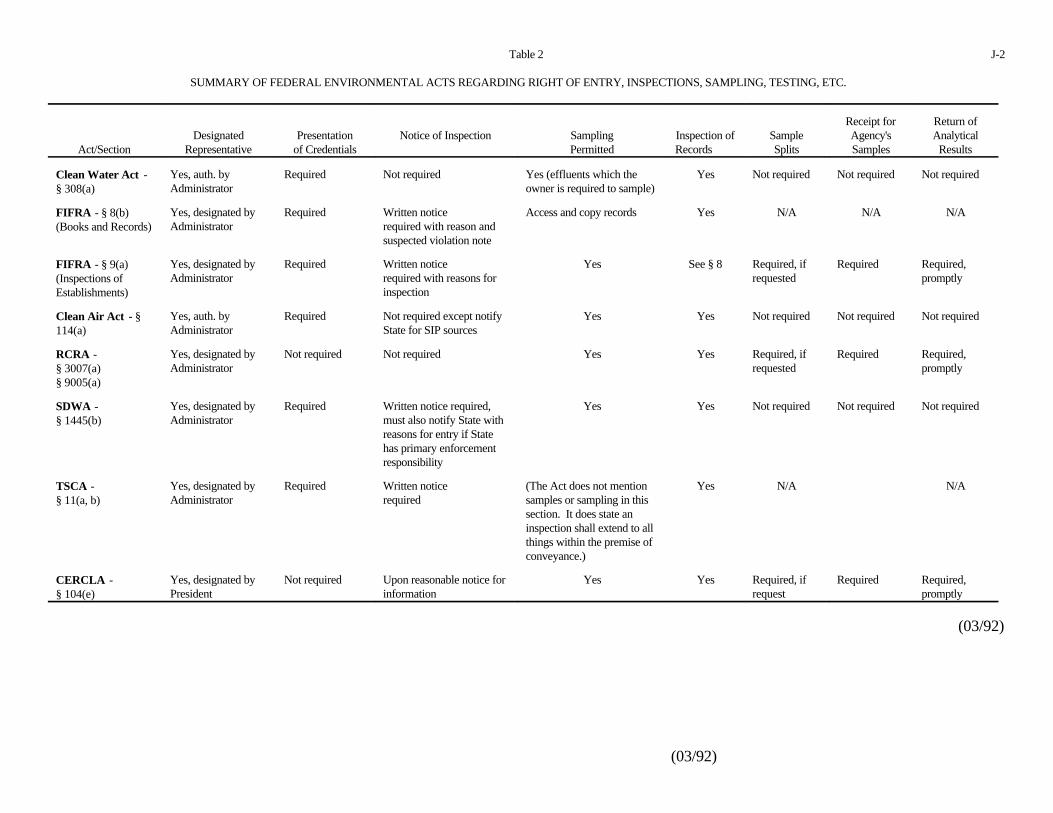
(03/92)
Table 2 J-2
SUMMARY OF FEDERAL ENVIRONMENTAL ACTS REGARDING RIGHT OF ENTRY, INSPECTIONS, SAMPLING, TESTING, ETC.
Act/Section Representative of Credentials Permitted Records Splits Samples ResultsDesignated Presentation Notice of Inspection Sampling Inspection of Sample Agency's Analytical
Receipt for Return of
Clean Water Act -§ 308(a)
Yes, auth. by Required Not required Yes (effluents which the Yes Not required Not required Not requiredAdministrator owner is required to sample)
FIFRA - § 8(b)(Books and Records)
Yes, designated by Required Written notice Access and copy records Yes N/A N/A N/AAdministrator required with reason and
suspected violation note
FIFRA - § 9(a)(Inspections ofEstablishments)
Yes, designated by Required Written notice Yes See § 8 Required, if Required Required,Administrator required with reasons for requested promptly
inspection
Clean Air Act - §114(a)
Yes, auth. by Required Not required except notify Yes Yes Not required Not required Not requiredAdministrator State for SIP sources
RCRA -§ 3007(a)§ 9005(a)
Yes, designated by Not required Not required Yes Yes Required, if Required Required,Administrator requested promptly
SDWA -§ 1445(b)
Yes, designated by Required Written notice required, Yes Yes Not required Not required Not requiredAdministrator must also notify State with
reasons for entry if Statehas primary enforcementresponsibility
TSCA -§ 11(a, b)
Yes, designated by Required Written notice (The Act does not mention Yes N/A N/AAdministrator required samples or sampling in this
section. It does state aninspection shall extend to allthings within the premise ofconveyance.)
CERCLA -§ 104(e)
Yes, designated by Not required Upon reasonable notice for Yes Yes Required, if Required Required,President information request promptly
(03/92)
(03/92)
K-1
Appendix K
PHOTOGRAPHS
When movies, slides, or photographs are taken which visually show the e ffluent or emission source
and/or any monitoring locati ons, they are numbered to correspond to logbook entries. The name of
the photographer, date, time, site location, and site description are entered sequentially in the logbook
as photos are taken. A series entry may be used for ra pid the aperture settings and shutter speeds for
photographs taken within the normal automatic exposure range. Special lenses, films, filters, or other
image enhancement techniques must be noted in the logbook. Chain-of-custody procedures depend
upon the subject matter, type of film, and the processing it requires. Film used for aeria l
photography, confidential information, or criminal investigations requir e chain-of-custody procedures.
Adequate logbook notations and receipts may be used to account for routine film processing. Once
developed, the slides or photographic print s shall be serially numbered corresponding to the logbook
descriptions and labeled.
MICROFILM
Microfilm is often used to copy documents that are or may later become TSCA Confidentia l
Business Information (CBI). This microfilm must be handled in accordance with the TSCA CB I
procedures (see Appendix I for additional inform ation and forms). Table C-1 is the NEIC procedure
for processing microfilm containing TSCA CBI documents.
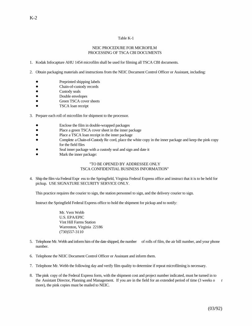
(03/92)
K-2
Table K-1
NEIC PROCEDURE FOR MICROFILM PROCESSING OF TSCA CBI DOCUMENTS
1. Kodak Infocapture AHU 1454 microfilm shall be used for filming all TSCA CBI documents.
2. Obtain packaging materials and instructions from the NEIC Document Control Officer or Assistant, including:
Preprinted shipping labelsChain-of-custody recordsCustody sealsDouble envelopesGreen TSCA cover sheetsTSCA loan receipt
3. Prepare each roll of microfilm for shipment to the processor.
Enclose the film in double-wrapped packagesPlace a green TSCA cover sheet in the inner packagePlace a TSCA loan receipt in the inner packageComplete a Chain-of-Custody Re cord, place the white copy in the inner package and keep the pink copyfor the field filesSeal inner package with a custody seal and sign and date itMark the inner package:
"TO BE OPENED BY ADDRESSEE ONLYTSCA CONFIDENTIAL BUSINESS INFORMATION"
4. Ship the film via Federal Expr ess to the Springfield, Virginia Federal Express office and instruct that it is to be held forpickup. USE SIGNATURE SECURITY SERVICE ONLY.
This practice requires the courier to sign, the station personnel to sign, and the delivery courier to sign.
Instruct the Springfield Federal Express office to hold the shipment for pickup and to notify:
Mr. Vern WebbU.S. EPA/EPICVint Hill Farms StationWarrenton, Virginia 22186(730)557-3110
5. Telephone Mr. Webb and inform him of the date shipped, the number of rolls of film, the air bill number, and your phonenumber.
6. Telephone the NEIC Document Control Officer or Assistant and inform them.
7. Telephone Mr. Webb the following day and verify film quality to determine if repeat microfilming is necessary.
8. The pink copy of the Federal Express form, with the shipment cost and project number indicated, must be turned in tothe Assistant Director, Planning and Management. If you are in the field for an extended period of time (3 weeks o rmore), the pink copies must be mailed to NEIC.
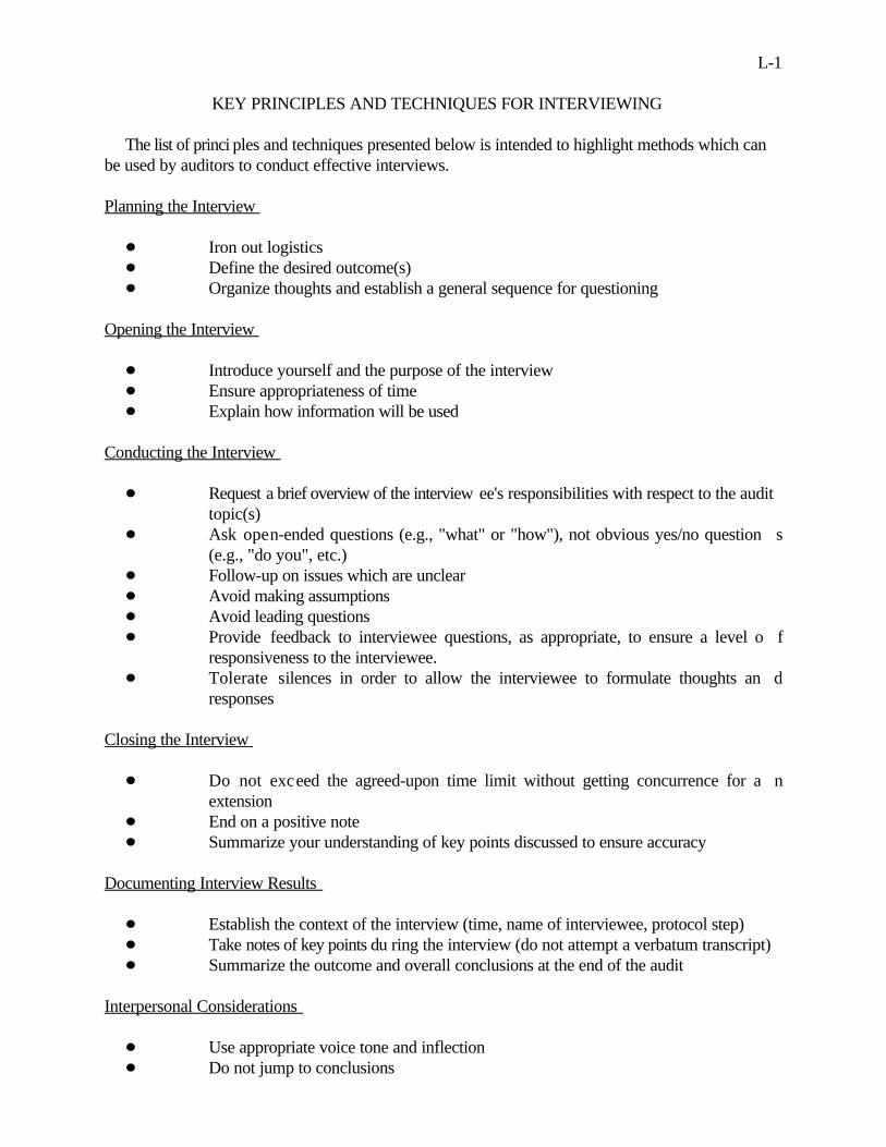
L-1
KEY PRINCIPLES AND TECHNIQUES FOR INTERVIEWING
The list of princi ples and techniques presented below is intended to highlight methods which canbe used by auditors to conduct effective interviews.
Planning the Interview
Iron out logisticsDefine the desired outcome(s)Organize thoughts and establish a general sequence for questioning
Opening the Interview
Introduce yourself and the purpose of the interviewEnsure appropriateness of timeExplain how information will be used
Conducting the Interview
Request a brief overview of the interview ee's responsibilities with respect to the audittopic(s)Ask open-ended questions (e.g., "what" or "how"), not obvious yes/no question s(e.g., "do you", etc.)Follow-up on issues which are unclearAvoid making assumptionsAvoid leading questionsProvide feedback to interviewee questions, as appropriate, to ensure a level o fresponsiveness to the interviewee.Tolerate silences in order to allow the interviewee to formulate thoughts an dresponses
Closing the Interview
Do not exceed the agreed-upon time limit without getting concurrence for a nextensionEnd on a positive noteSummarize your understanding of key points discussed to ensure accuracy
Documenting Interview Results
Establish the context of the interview (time, name of interviewee, protocol step)Take notes of key points du ring the interview (do not attempt a verbatum transcript)Summarize the outcome and overall conclusions at the end of the audit
Interpersonal Considerations
Use appropriate voice tone and inflectionDo not jump to conclusions
(03/92)
L-2
Interview Setting
Make sure the interviewee feels that there is sufficient privacyWhen appropriate, conduct the discussion in the interviewee's work areaTry to keep it "one-on-one"Minimize distractions
Non-Verbal Communication
Shake handsMaintain eye contactKeep the right distanceMirror the interviewee
M-1
(03/92)
Appendix M
SAMPLING GUIDELINES
The value of samples as evidence to document/support a violation is contingent upon many factors
including: (1) the method by which samples are collected; (2) the selection of sample containers ,
preserving samples after they are collected, and ensuring that proper holding times are adhered t o
between sample collection and analysis; (3) the accuracy or validity of field measurements that are
taken in conjunction with that sampling; (4) the adequate decontamination of field samplin g
equipment; (5) the degree to which appropr iate notes or other documentation pertaining to sampling
operations are logged in a notebo ok; and (6) the labeling of samples and employing a suitable chain-
of-custody system. M ost of these topics will be discussed in a relatively brief fashion in this section
of the document. For additional details, the reader should refer to any of the SOPs currently being
used by the Regions or NEIC. Other useful documents are program specific sampling/analytica l
protocols, such as 40 CFR Part 136 (NPDES), SW 846 (RCRA), and the Technical Enforcemen t
Guidance Document (RCRA).
SAMPLE COLLECTION
Samples can generally be divided into two separate and distinct categories: (1) environmenta l
samples and (2) source or waste samples. The collection of both will probably be necessary during
most multi-media inspections. Environmental samples can include surface /runoff water, groundwater,
sediment, surface wipes, soil, etc. Source or waste samples can include discharges from permitted
outfalls, PCB oil from electrical equipm ent, RCRA regulated "hazardous waste", treatment residues,
leachate, etc. In the case of any toxic/hazardous materials, the inspectors should make every effort
to have the facility collet the sample for them. Sampling of either category can be accomplished by
collecting grab samples, composite samples, or both. The type of sample ultimately obtained will be
predicated on satisfying a legal requirement such as a permit which specifies a type of sample ,
laboratory requirements, or ensuring that representativeness is achieved. A time-based composit e
sample will usually require the use of an autom atic sampler set to collect a series of discrete samples,
over the time period of interest. A spatially-based composite sample (actua lly a series of grab samples
blended together) and grab samples are collected by more conventional means and during a muc h
M-2
shorter time. Some type of dipper, scoop, auger, pump, corers, etc. can be used to collect a gra b
sample.
Perhaps the two most important points, the investi gators should keep in mind whenever sampling,
are identifying pr ecisely where the sample will be collected and selecting the appropriate equipment
to collet the sample. From a collection standpoint, a sample must often be obtained such that it is
representative of the entire media. If the media is well mixed and homogenous, a single sample will
probably be adequate to ensu re representativeness. If it is not well mixed, the investigator will have
to collect several samples at different loca tions, and composite them on an equally weighted or some
other basis or have each of the discrete sa mples analyzed. The total number of samples required will
largely depend upon the area/volume of the material and the degree of nonhomogeneity. Normally
in this case, the investigator will have to use a statistically random process to determine where the
samples should be colle cted. Laying out some type of imaginary grid to encompass the media to be
sampled and randomly selecting specific elements for sampling is one common method of ensuring
that bias is not introduced and that no other important statistic is compromised. In other cases, the
inspector must rely on a judgmental s ampling approach, particularly in situations where a worst case
result is desired. In that situation, the inspector should look for s igns of discoloration, wetness, waste
plumes or residue, dead vegetation, odor, or some other physical attribute or apply knowledge of the
situation (i.e., judgment) in an attempt too identify exactly wher e constituent concentrations are likely
to be highest. Other items that must be considered when selecting sampling sites are safety ,
convenience, and accessibility. The investigators should not collect samples until they have adequate
knowledge of the site, through touring/observing, interviewing, etc. too make prudent decision s
regarding selection of sampling sites.
The second important point the investigator should remember is to use the proper equipment to
physically collect the sample. The equipment should either be unused or decontaminated to an extent
that it cannot impart any contamination to the sample itself. Moreover, it is important to selec t
sampling equipment made of the proper material. Wherever possible, the material should be iner t
(i.e., teflon or stainless steel) and not contain, as its principal constituents, any of the sam e
constituents for which the samples will be analyzed. Lastly, the element of safety should not b e
overlooked. One key example would be where the investigators need to sample a potentiall y
hazardous waste from a 55-gallon drum. Opening the drum must be carefully performed prior t o
sampling.
M-3
(03/92)(03/92)
SAMPLE CONTAINERS, PRESERVATION METHODS, HOLDING TIMES, BLANKS
In order for the samples to be properly analyzed in the laboratory, the field investigators mus t
follow certain accepted procedures relative to the containers they use, the preservation of the samples
at time of collection, the holding time limits which dictate the quickness in which the samples must
be transported to the laboratory, and the use of field blanks for QA purposes. Each of thes e
procedures can vary from matrix to matrix, parameter to parameter, and in some cases, from program
to program. All of this information pertaining to sample collection/handling is summarized in th e
following two tables. One table corresponds to liquid samples and the other to nonliquid samples.
FIELD MEASUREMENTS
The acquisition of fi eld data is customarily required whenever sampling is performed. A number
of in situ monitoring devices/meters are used for this purpose, each o f which have certain applications
and limitations. These instruments ar e designed to withstand some rough handling without affecting
their stability or reliability. Paramete rs normally measured in the field include but, are not limited to,
dissolved oxygen, pH, temperature, and chlorine residual.
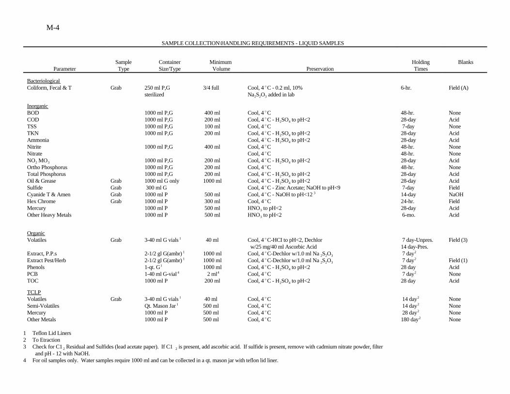
M-4
SAMPLE COLLECTION\HANDLING REQUIREMENTS - LIQUID SAMPLES
Parameter Type Size/Type Volume Preservation TimesSample Container Minimum Holding Blanks
BacteriologicalColiform, Fecal & T Grab 250 ml P,G 3/4 full Cool, 4 C - 0.2 ml, 10% 6-hr. Field (A)
sterilized Na S O added in lab2 2 3
InorganicBOD 1000 ml P,G 400 ml Cool, 4 C 48-hr. NoneCOD 1000 ml P,G 200 ml Cool, 4 C - H SO to pH<2 28-day AcidTSS 1000 ml P,G 100 ml Cool, 4 C 7-day NoneTKN 1000 ml P,G 200 ml Cool, 4 C - H SO to pH<2 28-day AcidAmmonia Cool, 4 C - H SO to pH<2 28-day AcidNitrite 1000 ml P,G 400 ml Cool, 4 C 48-hr. NoneNitrate Cool, 4 C 48-hr. NoneNO MO 1000 ml P,G 200 ml Cool, 4 C - H SO to pH<2 28-day Acid2 3
Ortho Phosphorus 1000 ml P,G 200 ml Cool, 4 C 48-hr. NoneTotal Phosphorus 1000 ml P,G 200 ml Cool, 4 C - H SO to pH<2 28-day AcidOil & Grease Grab 1000 ml G only 1000 ml Cool, 4 C - H SO to pH<2 28-day AcidSulfide Grab 300 ml G Cool, 4 C - Zinc Acetate; NaOH to pH<9 7-day FieldCyanide T & Amen Grab 1000 ml P 500 ml Cool, 4 C - NaOH to pH<12 14-day NaOHHex Chrome Grab 1000 ml P 300 ml Cool, 4 C 24-hr. FieldMercury 1000 ml P 500 ml HNO to pH<2 28-day AcidOther Heavy Metals 1000 ml P 500 ml HNO to pH<2 6-mo. Acid
2 4
2 4
2 4
2 4
2 4
2 4
3
3
3
Organic Volatiles Grab 3-40 ml G vials 40 ml Cool, 4 C-HCI to pH<2, Dechlor 7 day-Unpres. Field (3)
Extract, P.P.s 2-1/2 gl G(ambr) 1000 ml Cool, 4 C-Dechlor w/1.0 ml Na S O 7 dayExtract Pest/Herb 2-1/2 gl G(ambr) 1000 ml Cool, 4 C-Dechlor w/1.0 ml Na S O 7 day Field (1)Phenols 1-qt. G 1000 ml Cool, 4 C - H SO to pH<2 28 day AcidPCB 1-40 ml G-vial 2 ml Cool, 4 C 7 day NoneTOC 1000 ml P 200 ml Cool, 4 C - H SO to pH<2 28 day Acid
1
1
1
1
4 4
w/25 mg/40 ml Ascorbic Acid 14 day-Pres.2 2 3
2 2 3
2 4
2 4
2
2
2
TCLPVolatiles Grab 3-40 ml G vials 40 ml Cool, 4 C 14 day NoneSemi-Volatiles Qt. Mason Jar 500 ml Cool, 4 C 14 day NoneMercury 1000 ml P 500 ml Cool, 4 C 28 day NoneOther Metals 1000 ml P 500 ml Cool, 4 C 180 day None
1
1
2
2
2
2
1 Teflon Lid Liners2 To Etraction3 Check for C1 Residual and Sulfides (lead acetate paper). If C1 is present, add ascorbic acid. If sulfide is present, remove with cadmium nitrate powder, filter 2 2
and pH - 12 with NaOH.4 For oil samples only. Water samples require 1000 ml and can be collected in a qt. mason jar with teflon lid liner.
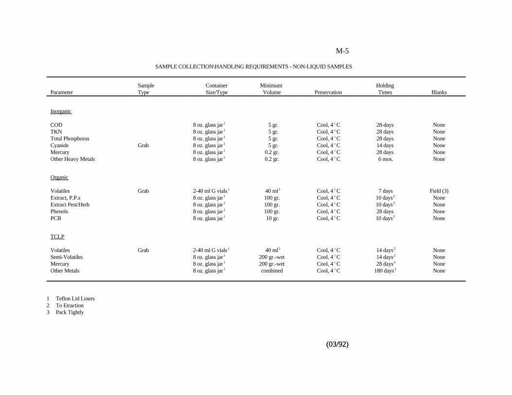
M-5
(03/92)(03/92)
SAMPLE COLLECTION\HANDLING REQUIREMENTS - NON-LIQUID SAMPLES
Parameter Type Size/Type Volume Preservation Times BlanksSample Container Minimum Holding
Inorganic
COD 8 oz. glass jar 5 gr. Cool, 4 C 28-days NoneTKN 8 oz. glass jar 5 gr. Cool, 4 C 28 days NoneTotal Phosphorus 8 oz. glass jar 5 gr. Cool, 4 C 28 days NoneCyanide Grab 8 oz. glass jar 5 gr. Cool, 4 C 14 days NoneMercury 8 oz. glass jar 0.2 gr. Cool, 4 C 28 days NoneOther Heavy Metals 8 oz. glass jar 0.2 gr. Cool, 4 C 6 mos. None
1
1
1
1
1
1
Organic
Volatiles Grab 2-40 ml G vials 40 ml Cool, 4 C 7 days Field (3)Extract, P.P.s 8 oz. glass jar 100 gr. Cool, 4 C 10 days NoneExtract Pest/Herb 8 oz. glass jar 100 gr. Cool, 4 C 10 days NonePhenols 8 oz. glass jar 100 gr. Cool, 4 C 28 days NonePCB 8 oz. glass jar 10 gr. Cool, 4 C 10 days None
1
1
1
1
1
3
2
2
2
TCLP
Volatiles Grab 2-40 ml G vials 40 ml Cool, 4 C 14 days NoneSemi-Volatiles 8 oz. glass jar 200 gr.-wet Cool, 4 C 14 days NoneMercury 8 oz. glass jar 200 gr.-wet Cool, 4 C 28 days NoneOther Metals 8 oz. glass jar combined Cool, 4 C 180 days None
1
1
1
1
3 2
2
2
2
1 Teflon Lid Liners2 To Etraction3 Pack Tightly
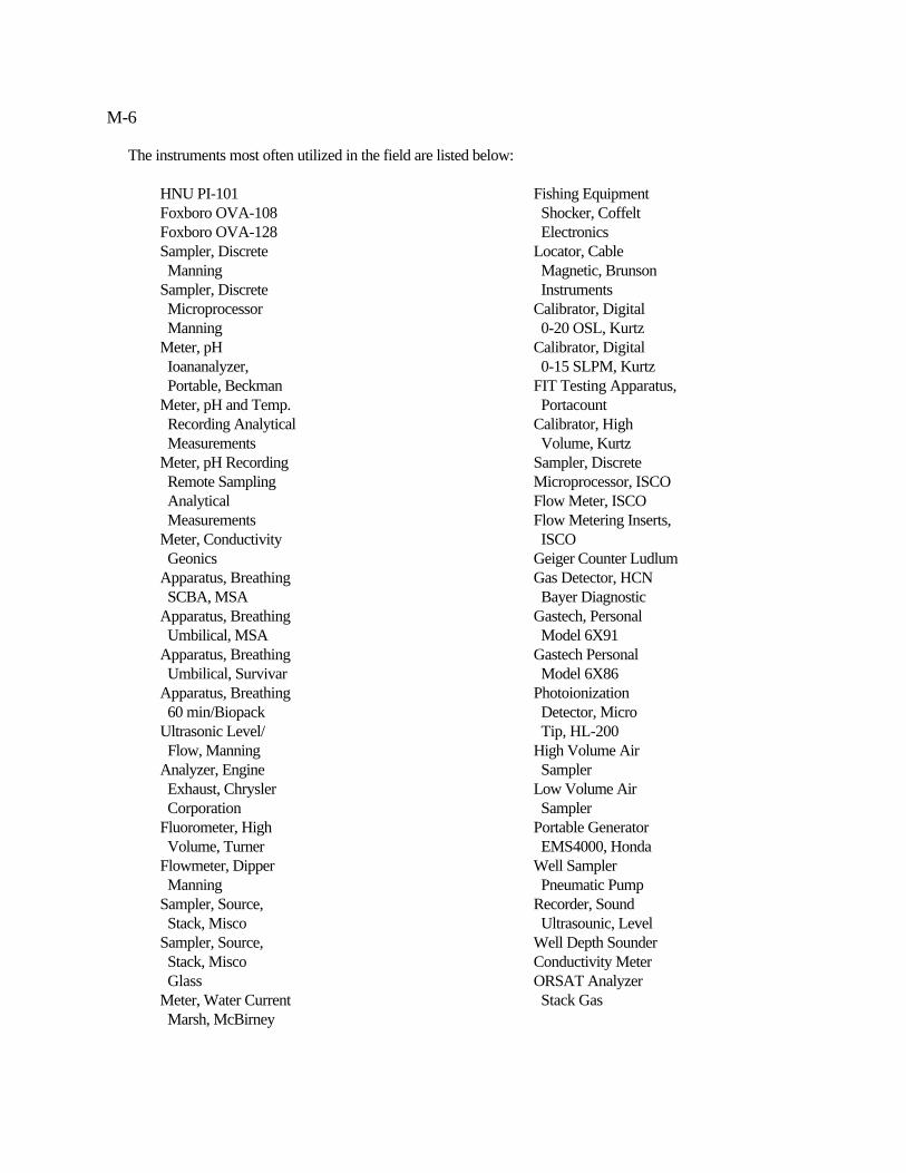
M-6
The instruments most often utilized in the field are listed below:
HNU PI-101 Fishing EquipmentFoxboro OVA-108 Shocker, CoffeltFoxboro OVA-128 ElectronicsSampler, Discrete Locator, Cable Manning Magnetic, BrunsonSampler, Discrete Instruments Microprocessor Calibrator, Digital Manning 0-20 OSL, KurtzMeter, pH Calibrator, Digital Ioananalyzer, 0-15 SLPM, Kurtz Portable, Beckman FIT Testing Apparatus,Meter, pH and Temp. Portacount Recording Analytical Calibrator, High Measurements Volume, KurtzMeter, pH Recording Sampler, Discrete Remote Sampling Microprocessor, ISCO Analytical Flow Meter, ISCO Measurements Flow Metering Inserts, Meter, Conductivity ISCO Geonics Geiger Counter LudlumApparatus, Breathing Gas Detector, HCN SCBA, MSA Bayer DiagnosticApparatus, Breathing Gastech, Personal Umbilical, MSA Model 6X91Apparatus, Breathing Gastech Personal Umbilical, Survivar Model 6X86Apparatus, Breathing Photoionization 60 min/Biopack Detector, MicroUltrasonic Level/ Tip, HL-200 Flow, Manning High Volume AirAnalyzer, Engine Sampler Exhaust, Chrysler Low Volume Air Corporation SamplerFluorometer, High Portable Generator Volume, Turner EMS4000, HondaFlowmeter, Dipper Well Sampler Manning Pneumatic PumpSampler, Source, Recorder, Sound Stack, Misco Ultrasounic, LevelSampler, Source, Well Depth Sounder Stack, Misco Conductivity Meter Glass ORSAT AnalyzerMeter, Water Current Stack Gas Marsh, McBirney
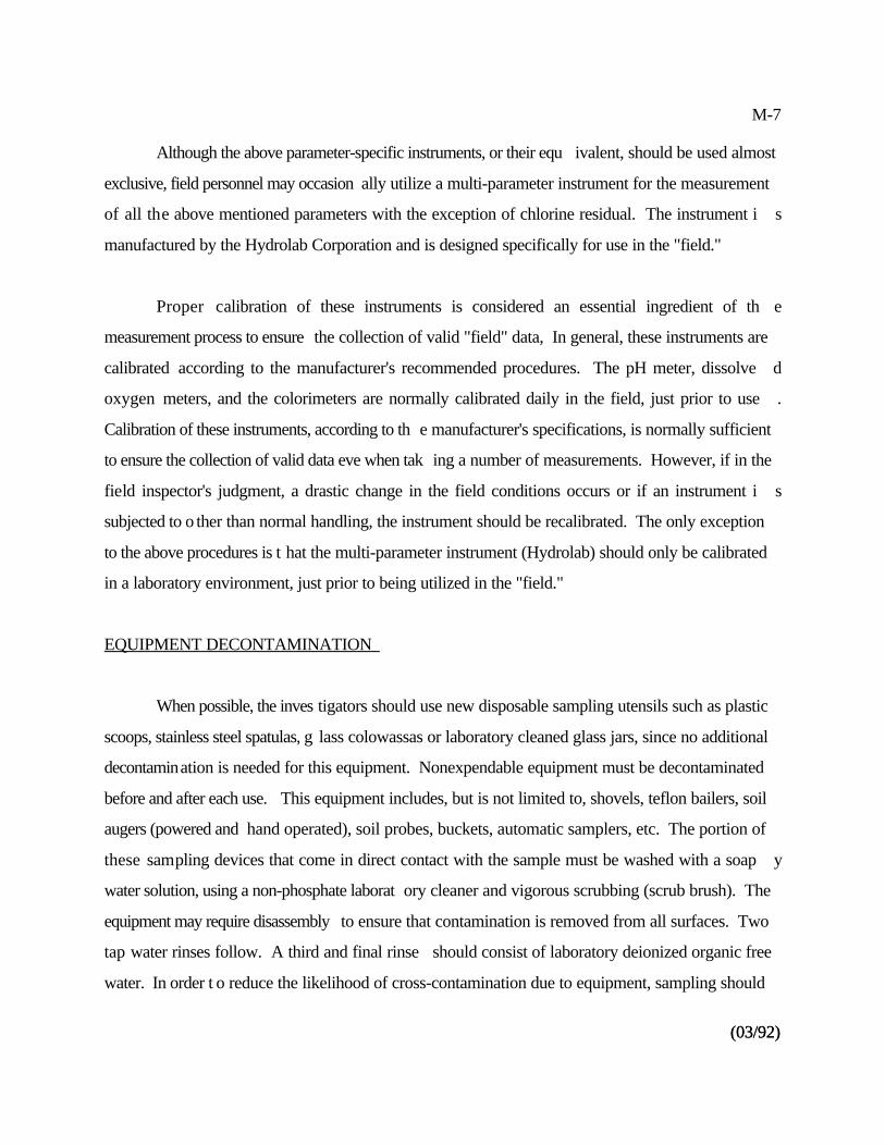
M-7
(03/92)(03/92)
Although the above parameter-specific instruments, or their equ ivalent, should be used almost
exclusive, field personnel may occasion ally utilize a multi-parameter instrument for the measurement
of all the above mentioned parameters with the exception of chlorine residual. The instrument i s
manufactured by the Hydrolab Corporation and is designed specifically for use in the "field."
Proper calibration of these instruments is considered an essential ingredient of th e
measurement process to ensure the collection of valid "field" data, In general, these instruments are
calibrated according to the manufacturer's recommended procedures. The pH meter, dissolve d
oxygen meters, and the colorimeters are normally calibrated daily in the field, just prior to use .
Calibration of these instruments, according to th e manufacturer's specifications, is normally sufficient
to ensure the collection of valid data eve when tak ing a number of measurements. However, if in the
field inspector's judgment, a drastic change in the field conditions occurs or if an instrument i s
subjected to o ther than normal handling, the instrument should be recalibrated. The only exception
to the above procedures is t hat the multi-parameter instrument (Hydrolab) should only be calibrated
in a laboratory environment, just prior to being utilized in the "field."
EQUIPMENT DECONTAMINATION
When possible, the inves tigators should use new disposable sampling utensils such as plastic
scoops, stainless steel spatulas, g lass colowassas or laboratory cleaned glass jars, since no additional
decontamination is needed for this equipment. Nonexpendable equipment must be decontaminated
before and after each use. This equipment includes, but is not limited to, shovels, teflon bailers, soil
augers (powered and hand operated), soil probes, buckets, automatic samplers, etc. The portion of
these sampling devices that come in direct contact with the sample must be washed with a soap y
water solution, using a non-phosphate laborat ory cleaner and vigorous scrubbing (scrub brush). The
equipment may require disassembly to ensure that contamination is removed from all surfaces. Two
tap water rinses follow. A third and final rinse should consist of laboratory deionized organic free
water. In order t o reduce the likelihood of cross-contamination due to equipment, sampling should
M-8
proceed from cleanest areas first to dirtiest areas last, whene ver possible. Between sampling stations,
the equipment is decontaminated, as described above. At some point during the sampling effort ,
deionized organic free lab water should be passed through or over the newly decontaminate d
sampling equipment and then sampled to ensure that the decontamination procedure was effective.
This so-called equipment blank should be preserved, return to the laboratory using appropriate chain-
of-custody procedures, and analyzed for the same parameters as the actual samples. The abov e
decontamination procedure can be modified for specific parameters and condition, if deeme d
necessary by the team leader.
Solvents should only be used if proper dec ontamination cannot be obtained with soapy water
(e.g., heavy petroleum products) or if specifically requested. If a solvent is used, the laborator y
analyzing the samples should be consult to ensure the solvent of choice will not interfere with th e
analytical procedure or mask the results.
SAMPLE LOGGING
A sample log should be maintained in a bound log book which documents all samples that are
collected. This log should include a unique sample number (if needed), date, time, sample medium
(soil, liquid, etc.), preservative (if any), parameters, and location. Included with the log are an y
observations made by the sampler t hat would otherwise identify the sample or conditions at the time
of sampling. If photographs are taken, that should also be noted in the field log book.
SAMPLE SPLITTING
Often, it will be necessary to collect duplicate s amples or to split a sample in order to provide
the facility with a separate sample it can analyze on its own. In these situations, every effort should
be made to ens ure that both samples are as identical as possible and should theoretically yield th e
same results. Bulk samples (liquid) for parameters such as extractable organics, cyanide, nutrients,
PCB, metals, etc. may be collected in a larger container and alternately poured into the appropriate
M-9
(03/92)(03/92)
sample containers. However, the liquid should be well mixed during the transfer. EPA normall y
provides the sample containers.
Certain parameters may not be split using the above method (e.g., volatile organics, semi -
volatiles, and oil and grease) since these samples must be collected and analyzed in their origina l
container. This ty pe of sample should not be distributed by splitting since it may cause air stripping
of the volatiles or, in the case of the oil and g rease, a residue may adhere to the sample container and
cause an erroneous measurement. These parameters will necessitate collecting duplicate samples ,
virtually at the same time and at the same place to assure homogeneity.
Samples of solid matrices such as sludge, soil, or sediment may be placed into a sufficiently
large container and either hand agitated and/or mechanically mixed with a blender, etc. to achieve a
homogeneous consistency, except for volatile or semi-volatile analyses. Individual samples may then
be placed in the appropriate containers.
Wipe samples (PCB), due to their nature, must be collected immediately adjacent to eac h
other with each party receiving a separate sample.
CHAIN-OF-CUSTODY
Since there are legal impl ications when sampling data is used as evidence, EPA must be able
to demonstrate that the samples were protected from tampering from the time of collection to th e
time they are introduced as evidence. This demonstration is ba sed on samples being in the possession
or custody of an EPA employee at all times, and it is documented by means of a chain-of-custod y
record. Custody implies both physical possession as well as controlled access by locking in a secured
area. The chain-of-custody record indicates who had possessio at any given point in time and how
and when transfer of custody from one individual to another occurred.
M-10
Each sample container should be affixed with a sample tag to ensure chain-of-custody from
the sample location to the laboratory (see next section for further details). The tag contains th e
sample location, the sampler's signature, preserved (Y or N), parameter(s), and sample typ e
(composite or grab) and it must be completely filled out using waterproof ink.
Pressure sensitive tape affixed to the container may also be used under certain circumstances
to identify the sample. Ink used to write on the container must be waterproof. At a minimum, the
label must contain the following information: location, date, time, sample number (if needed), and
preservative used. The sampler should be certain that the label is securely affixed to the outside of
the container and will not peel off during shipment.
The chain-of-custody record is co mprised of sample tags and the record form itself. Both of
these are shown on the following pages. A sample tag should be completed for each sample by the
field sampler using waterproof ink, if possible. It should be affixed to t he sample container in a secure
manner. The field sampler should also complete the chain-of-custody record form, appropriatel y
describing all samples that he/she was responsible for collecting. The same wording must be used on
both the tag and form, and car e must be exercised to make sure that all the information in the chain-
of-custody record corresponds properly without discrepancies. While the samples are in his/he r
custody, all necessary precautions should be taken by the field sampler to ensure that they ar e
adequate ly safeguarded. Whenever the possession of samples is transferred, the individual s
relinquishing and receiving will sign, date , and note the time on the record. The record will continue
to accompany the samples. At the completion of the process, a copy of all of the chain-of-custody
records will be provided to the team leader for filing.
TRANSPORTATION
All samples will be properly packed in suitable ice chests and transp orted back to the Regional
Laboratory via vehicle or private transport. Chain-of-Custody record forms should also be affixed
to the ice che sts. The inspectors should always lock the vehicles in which samples are bein g
M-11
(03/92)(03/92)
transported . There may be times when DOT regulations will have to be followed. At least on e
member of the inspection team should review the DOT requirement s prior to an inspection, and make
certain that they are complied with in cases w here samples are unusually hazardous or travel through
tunnels or if confined/special areas are encountered.
N-1
40 CFR 268.40, 41, 42, and 43 contain the treatment standards.*
40 CFR 261 defines listed and characteristic wastes.**
(03/92)
Appendix N
LAND DISPOSAL RESTRICTIONS PROGRAM
BASIC PROGRAM
Land Disposal Restrictions (LDR), 40 CFR 268, are phased regulations prohibiting lan d
disposal of hazardous waste unless that waste meets the applicable treatment standards. Land*
disposal includes but is not limited to placement in a landfill, surface impoundment, waste pile ,
injection well, land trea tment facility, salt dome formation, salt bed formation, underground mine or
cave, or placement in a concrete vault or bunker intended for disposal purposes. The applicabl e
treatment standards are expressed as either concentrations of contaminants in the extract or tota l
waste and as specified technologies.
The schedule for the different groups of waste is:
Solvents and Dioxins: banned from land disposal ( unless treated) effective November
8, 1986 and November 8, 1988, respectively
"California List" Waste: This group includes liquid wastes containing metals, fre e
cyanides, polychlorinate d biphenyls, corrosives (pH less than 2.0) and certain wastes
containing halogenated organic compounds. Solid hazardous waste containin g
halogenated organic compounds are also included. These wastes were banne d
effective July 8, 1987
"First, Second, and Third Third" Wastes: The remaining listed and characteristi c
wastes were divided into thirds (see 40 CFR 268 for specific waste groupings). The**
N-2
(03/92)
first third wastes were banned effective August 8, 1988, second third June 8, 198 9
and the third third May 8, 1990.
Newly Listed Wastes: New wastes that become listed after November 8, 1984 will
be banned on a case-by-case basis. There is no statutory deadline for determinin g
treatment standards.
The effective dates for banning these wastes from land disposal can be modified by several kinds of
variances. 40 CFR 268, Appendix VII includes all of the different effective dates for each type o f
waste. Effective dates can be modified by any of the following:
National capacity variance
Case-by-case extension
Treatability variance
Equivalent method variance
No-migration petition
Surface impoundment exemption
Generators of restricted waste are required to:
Determine whether they generate restricted wastes
Determine waste treatment standards
Determine whether waste exceeds treatment standards
Provide for appropriate treatment and/or disposal
Satisfy documentation, recordkeeping, notification, certification, packaging, an d
manifesting requirements
Meet applicable requirements if the generator is or becomes a TSDF
N-3
(03/92)
Treatment, storage, and disposal facilities are required to:
Ensure compliance with generator recordkeeping requirements when residue s
generated from treating restricted wastes are manifested off-site
Certify that treatment standards have been achieved for particular wastes prior t o
disposal
To become familiar with all of the requirements of LDR, refer to 40 CFR 268 and the Land
Disposal Restrictions - Summary of Requirements, OSWER 9934.0-1A, February 1991 for a
complete discussion.
EVALUATING COMPLIANCE
LDR requires substantial documentation certifying waste types, required treatment, an d
notifying waste handlers o f the regulatory requirements. Interviews and field observations also may
be helpful.
Interview may cover:
Who fills out the LDR notifications and certifications
Frequency of sampling and methods used for sampling and analysis
Documentation required to be kept by a generator include:
LDR notifications and certifications
Waste analysis plan if treating a prohibited waste in tanks or containers
Documentation required for TSDFs include:
N-4
(03/92)
Storage
- Waste analyses and results
- Waste analysis plan (provision for determining whether a waste is prohibited)
Treatment
- Waste analysis plan
Land Disposal Facility
- Generator and treatment facility notifications and certifications
- Waste analysis plan
Field/visual observations related to LDR requirements can be incorporated into a genera l
storage facility inspection. LDR requirements can be incorporated into a general storage facilit y
inspection. LDR wastes cannot be stored longer than 1 year unless the facility can show that th e
storage is solely for the purpose of accumulation of sufficient qu antities of hazardous waste necessary
to facilitate proper recovery, treatment, or disposal. Wastes that are placed in storage prior to the
effective date of the restrictions for that waste are not subject to the LDR restrictions on storage .
A quick check of a ccumulation dates on labels will determine how long a drum has been in storage.
Be sure to note the hazardous waste number.
Refer to the Land Disposal Restrictions - Inspection Manual, OSWER 9938.1A, Februar y
1989, for a complete discussion on how to conduct an LDR inspection. Keep in mind that thi s
document has yet to be updated with information regarding the Third Third wastes.
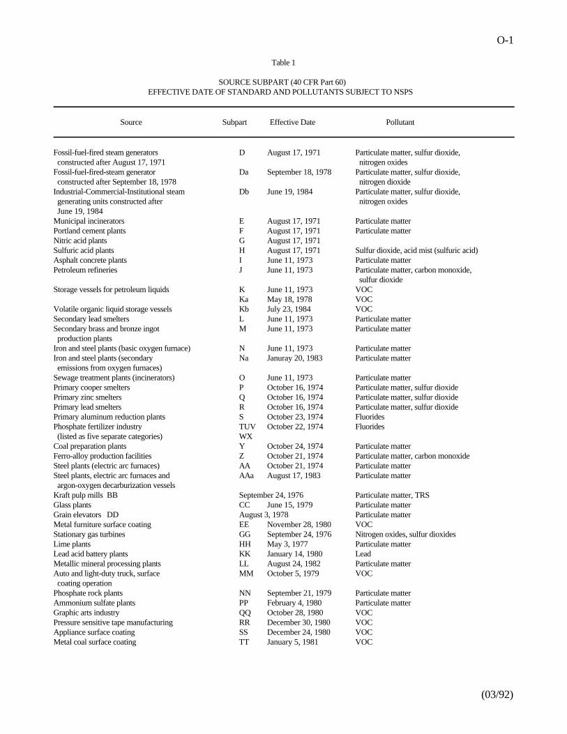
O-1
(03/92)
Table 1
SOURCE SUBPART (40 CFR Part 60)EFFECTIVE DATE OF STANDARD AND POLLUTANTS SUBJECT TO NSPS
Source Subpart Effective Date Pollutant
Fossil-fuel-fired steam generators D August 17, 1971 Particulate matter, sulfur dioxide, constructed after August 17, 1971 nitrogen oxidesFossil-fuel-fired-steam generator Da September 18, 1978 Particulate matter, sulfur dioxide, constructed after September 18, 1978 nitrogen dioxide Industrial-Commercial-Institutional steam Db June 19, 1984 Particulate matter, sulfur dioxide, generating units constructed after nitrogen oxides June 19, 1984Municipal incinerators E August 17, 1971 Particulate matterPortland cement plants F August 17, 1971 Particulate matterNitric acid plants G August 17, 1971Sulfuric acid plants H August 17, 1971 Sulfur dioxide, acid mist (sulfuric acid)Asphalt concrete plants I June 11, 1973 Particulate matterPetroleum refineries J June 11, 1973 Particulate matter, carbon monoxide,
sulfur dioxideStorage vessels for petroleum liquids K June 11, 1973 VOC
Ka May 18, 1978 VOCVolatile organic liquid storage vessels Kb July 23, 1984 VOCSecondary lead smelters L June 11, 1973 Particulate matterSecondary brass and bronze ingot M June 11, 1973 Particulate matter production plantsIron and steel plants (basic oxygen furnace) N June 11, 1973 Particulate matterIron and steel plants (secondary Na Januray 20, 1983 Particulate matter emissions from oxygen furnaces)Sewage treatment plants (incinerators) O June 11, 1973 Particulate matterPrimary cooper smelters P October 16, 1974 Particulate matter, sulfur dioxidePrimary zinc smelters Q October 16, 1974 Particulate matter, sulfur dioxidePrimary lead smelters R October 16, 1974 Particulate matter, sulfur dioxidePrimary aluminum reduction plants S October 23, 1974 FluoridesPhosphate fertilizer industry TUV October 22, 1974 Fluorides (listed as five separate categories) WXCoal preparation plants Y October 24, 1974 Particulate matterFerro-alloy production facilities Z October 21, 1974 Particulate matter, carbon monoxideSteel plants (electric arc furnaces) AA October 21, 1974 Particulate matterSteel plants, electric arc furnaces and AAa August 17, 1983 Particulate matter argon-oxygen decarburization vesselsKraft pulp mills BB September 24, 1976 Particulate matter, TRSGlass plants CC June 15, 1979 Particulate matterGrain elevators DD August 3, 1978 Particulate matterMetal furniture surface coating EE November 28, 1980 VOCStationary gas turbines GG September 24, 1976 Nitrogen oxides, sulfur dioxidesLime plants HH May 3, 1977 Particulate matterLead acid battery plants KK January 14, 1980 LeadMetallic mineral processing plants LL August 24, 1982 Particulate matterAuto and light-duty truck, surface MM October 5, 1979 VOC coating operationPhosphate rock plants NN September 21, 1979 Particulate matterAmmonium sulfate plants PP February 4, 1980 Particulate matterGraphic arts industry QQ October 28, 1980 VOCPressure sensitive tape manufacturing RR December 30, 1980 VOCAppliance surface coating SS December 24, 1980 VOCMetal coal surface coating TT January 5, 1981 VOC
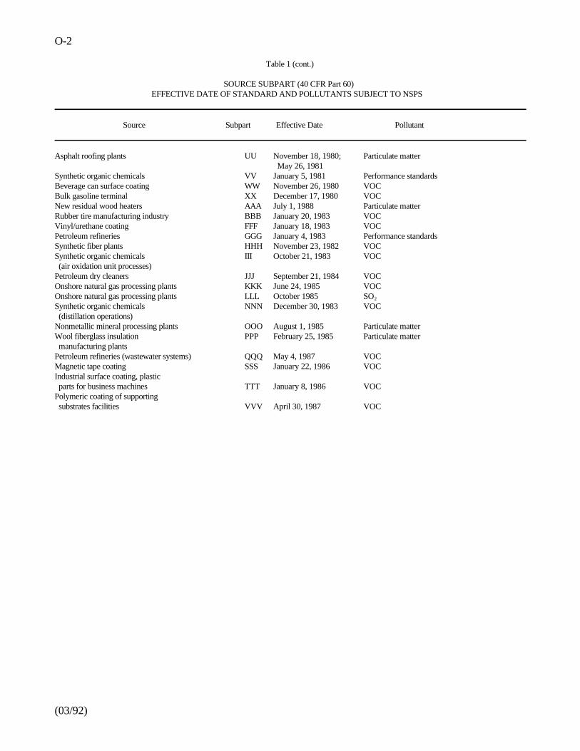
O-2
(03/92)
Table 1 (cont.)
SOURCE SUBPART (40 CFR Part 60)EFFECTIVE DATE OF STANDARD AND POLLUTANTS SUBJECT TO NSPS
Source Subpart Effective Date Pollutant
Asphalt roofing plants UU November 18, 1980; Particulate matter May 26, 1981
Synthetic organic chemicals VV January 5, 1981 Performance standardsBeverage can surface coating WW November 26, 1980 VOCBulk gasoline terminal XX December 17, 1980 VOCNew residual wood heaters AAA July 1, 1988 Particulate matterRubber tire manufacturing industry BBB January 20, 1983 VOCVinyl/urethane coating FFF January 18, 1983 VOCPetroleum refineries GGG January 4, 1983 Performance standardsSynthetic fiber plants HHH November 23, 1982 VOCSynthetic organic chemicals III October 21, 1983 VOC (air oxidation unit processes)Petroleum dry cleaners JJJ September 21, 1984 VOCOnshore natural gas processing plants KKK June 24, 1985 VOCOnshore natural gas processing plants LLL October 1985 SO2
Synthetic organic chemicals NNN December 30, 1983 VOC (distillation operations)Nonmetallic mineral processing plants OOO August 1, 1985 Particulate matterWool fiberglass insulation PPP February 25, 1985 Particulate matter manufacturing plantsPetroleum refineries (wastewater systems) QQQ May 4, 1987 VOCMagnetic tape coating SSS January 22, 1986 VOCIndustrial surface coating, plastic parts for business machines TTT January 8, 1986 VOCPolymeric coating of supporting substrates facilities VVV April 30, 1987 VOC
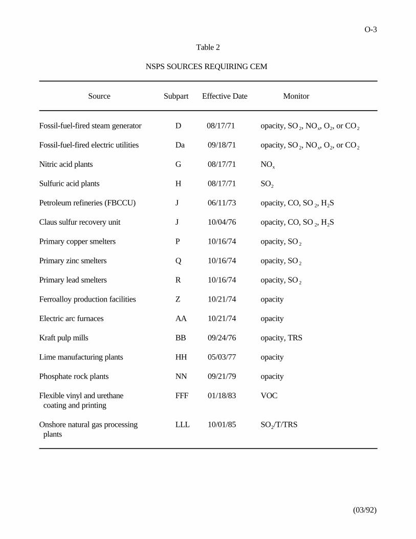
O-3
(03/92)
Table 2
NSPS SOURCES REQUIRING CEM
Source Subpart Effective Date Monitor
Fossil-fuel-fired steam generator D 08/17/71 opacity, SO , NO , O , or CO 2 x 2 2
Fossil-fuel-fired electric utilities Da 09/18/71 opacity, SO , NO , O , or CO2 x 2 2
Nitric acid plants G 08/17/71 NOx
Sulfuric acid plants H 08/17/71 SO2
Petroleum refineries (FBCCU) J 06/11/73 opacity, CO, SO , H S2 2
Claus sulfur recovery unit J 10/04/76 opacity, CO, SO , H S2 2
Primary copper smelters P 10/16/74 opacity, SO 2
Primary zinc smelters Q 10/16/74 opacity, SO 2
Primary lead smelters R 10/16/74 opacity, SO 2
Ferroalloy production facilities Z 10/21/74 opacity
Electric arc furnaces AA 10/21/74 opacity
Kraft pulp mills BB 09/24/76 opacity, TRS
Lime manufacturing plants HH 05/03/77 opacity
Phosphate rock plants NN 09/21/79 opacity
Flexible vinyl and urethane FFF 01/18/83 VOC coating and printing
Onshore natural gas processing LLL 10/01/85 SO /T/TRS2
plants
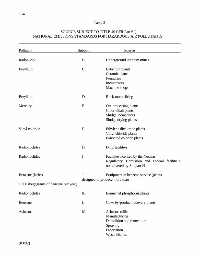
O-4
(03/92)
Table 3
SOURCE SUBJECT TO TITLE 40 CFR Part 61)NATIONAL EMISSIONS STANDARDS FOR HAZARDOUS AIR POLLUTANTS
Pollutant Subpart Source
Radon-222 B Underground uranium mines
Beryllium C Extaction plantsCeramic plantsFoundriesIncineratorsMachine shops
Beryllium D Rock motor firing
Mercury E Ore processing plantsChlor-alkali plantsSludge incineratorsSludge drying plants
Vinyl chloride F Ethylene dichloride plantsVinyl chloride plantsPolyvinyl chloride plants
Radionuclides H DOE facilities
Radionuclides I Facilities licensed by the NuclearRegulatory Comission and Federal facilitie snot covered by Subpart H
Benzene (leaks) J Equipment in benzene service (plants designed to produce more than
1,000 megagrams of benzene per year)
Radionuclides K Elemental phosphorus plants
Benzene L Coke by-product recovery plants
Asbestos M Asbestos millsManufacturingDemolition and renovationSprayingFabricationWaste disposal
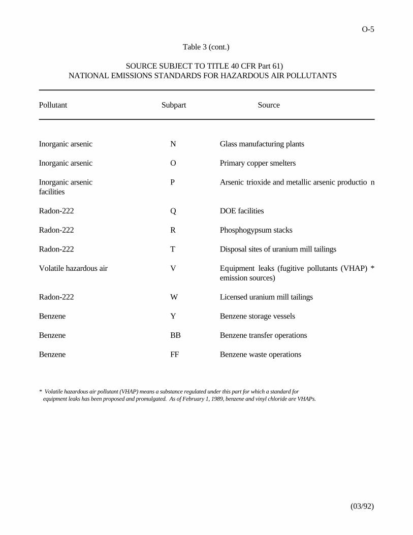
O-5
(03/92)
Table 3 (cont.)
SOURCE SUBJECT TO TITLE 40 CFR Part 61)NATIONAL EMISSIONS STANDARDS FOR HAZARDOUS AIR POLLUTANTS
Pollutant Subpart Source
Inorganic arsenic N Glass manufacturing plants
Inorganic arsenic O Primary copper smelters
Inorganic arsenic P Arsenic trioxide and metallic arsenic productio nfacilities
Radon-222 Q DOE facilities
Radon-222 R Phosphogypsum stacks
Radon-222 T Disposal sites of uranium mill tailings
Volatile hazardous air V Equipment leaks (fugitive pollutants (VHAP) *emission sources)
Radon-222 W Licensed uranium mill tailings
Benzene Y Benzene storage vessels
Benzene BB Benzene transfer operations
Benzene FF Benzene waste operations
* Volatile hazardous air pollutant (VHAP) means a substance regulated under this part for which a standard for equipment leaks has been proposed and promulgated. As of February 1, 1989, benzene and vinyl chloride are VHAPs.
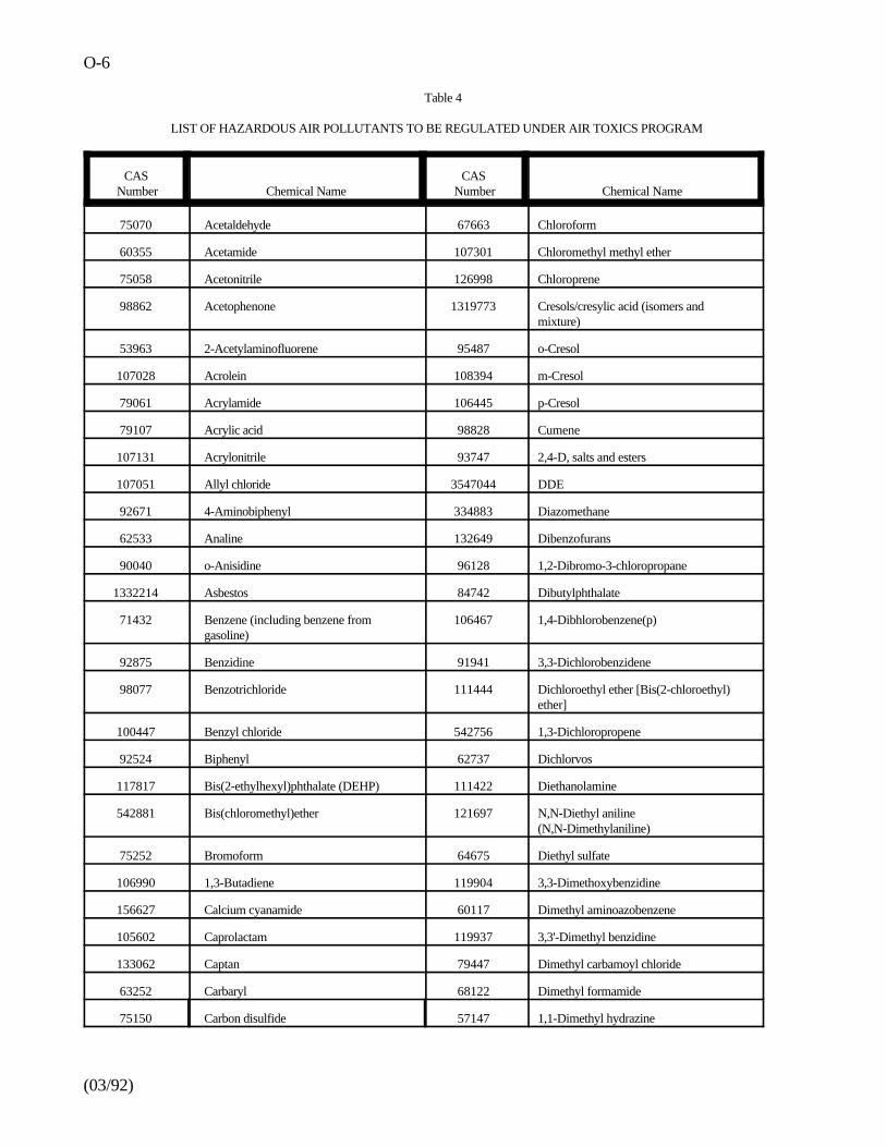
O-6
(03/92)
Table 4
LIST OF HAZARDOUS AIR POLLUTANTS TO BE REGULATED UNDER AIR TOXICS PROGRAM
CAS CAS Number Chemical Name Number Chemical Name
75070 Acetaldehyde 67663 Chloroform
60355 Acetamide 107301 Chloromethyl methyl ether
75058 Acetonitrile 126998 Chloroprene
98862 Acetophenone 1319773 Cresols/cresylic acid (isomers andmixture)
53963 2-Acetylaminofluorene 95487 o-Cresol
107028 Acrolein 108394 m-Cresol
79061 Acrylamide 106445 p-Cresol
79107 Acrylic acid 98828 Cumene
107131 Acrylonitrile 93747 2,4-D, salts and esters
107051 Allyl chloride 3547044 DDE
92671 4-Aminobiphenyl 334883 Diazomethane
62533 Analine 132649 Dibenzofurans
90040 o-Anisidine 96128 1,2-Dibromo-3-chloropropane
1332214 Asbestos 84742 Dibutylphthalate
71432 Benzene (including benzene from 106467 1,4-Dibhlorobenzene(p)gasoline)
92875 Benzidine 91941 3,3-Dichlorobenzidene
98077 Benzotrichloride 111444 Dichloroethyl ether [Bis(2-chloroethyl)ether]
100447 Benzyl chloride 542756 1,3-Dichloropropene
92524 Biphenyl 62737 Dichlorvos
117817 Bis(2-ethylhexyl)phthalate (DEHP) 111422 Diethanolamine
542881 Bis(chloromethyl)ether 121697 N,N-Diethyl aniline(N,N-Dimethylaniline)
75252 Bromoform 64675 Diethyl sulfate
106990 1,3-Butadiene 119904 3,3-Dimethoxybenzidine
156627 Calcium cyanamide 60117 Dimethyl aminoazobenzene
105602 Caprolactam 119937 3,3'-Dimethyl benzidine
133062 Captan 79447 Dimethyl carbamoyl chloride
63252 Carbaryl 68122 Dimethyl formamide
75150 Carbon disulfide 57147 1,1-Dimethyl hydrazine
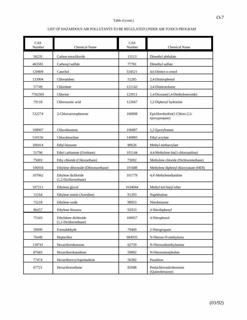
Table 4 (cont.)
LIST OF HAZARDOUS AIR POLLUTANTS TO BE REGULATED UNDER AIR TOXICS PROGRAM
O-7
(03/92)
CAS CAS Number Chemical Name Number Chemical Name
56235 Carbon tetrachloride 13113 Dimethyl phthalate
463581 Carbonyl sulfide 77781 Dimethyl sulfate
120809 Catechol 534521 4,6-Dinitro-o-cresol
133904 Chloramben 51285 2,4-Dinitrophenol
57749 Chlordane 121142 2,4-Dinitrotoluene
7782505 Chlorine 123911 1,4-Dioxane(1,4-Diethyleneoxide)
79118 Chloroacetic acid 122667 1,2-Diphenyl hydrazine
532274 2-Chloroacetophenone 106898 Epichlorohydrin(1-Chloro-2,3-epoxypropane)
108907 Chlorobenzene 106887 1,2-Epoxybutane
510156 Chlorobenzilate 140885 Ethyl acrylate
100414 Ethyl benzene 80626 Methyl methacrylate
51796 Ethyl carbamate (Urethane) 101144 4,4-Methylene bis(2-chloroaniline)
75003 Ethy chloride (Chloroethane) 75092 Methylene chloride (Dichloromethane)
106934 Ethylene dibromide (Dibromoethane) 101688 Methylene diphenyl diisocyanate (MDI)
107062 Ethylene dichloride 101779 4,4'-Methylenedianiline(1,2-Dichloroethane)
107211 Ethylene glycol 1634044 Methyl tert-butyl ether
15164 Ethylene iminie (Aziridine) 91203 Naphthalene
75218 Ethylene oxide 98953 Nitrobenzene
96457 Ethylene thiourea 92933 4-Nitrobiphenyl
75343 Ethylidene dichloride 100027 4-Nitrophenol(1,1-Dichloroethane)
50000 Formaldehyde 79469 2-Nitropropane
76448 Heptachlor 684935 N-Nitroso-N-methylurea
118741 Hexachlorobenzene 62759 N-Nitrosodimethylamine
87683 Hexachlorobutadiene 59892 N-Nitrosomorpholine
77474 Hexachlorocyclopentadiene 56382 Parathion
67721 Hexachloroethane 82688 Pentachloronitrobenzene(Quintobenzene)
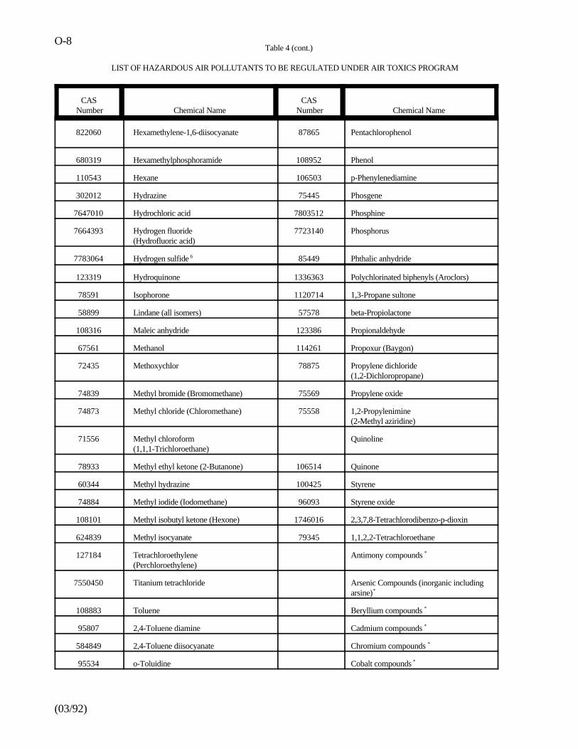
Table 4 (cont.)
LIST OF HAZARDOUS AIR POLLUTANTS TO BE REGULATED UNDER AIR TOXICS PROGRAM
O-8
(03/92)
CAS CAS Number Chemical Name Number Chemical Name
822060 Hexamethylene-1,6-diisocyanate 87865 Pentachlorophenol
680319 Hexamethylphosphoramide 108952 Phenol
110543 Hexane 106503 p-Phenylenediamine
302012 Hydrazine 75445 Phosgene
7647010 Hydrochloric acid 7803512 Phosphine
7664393 Hydrogen fluoride 7723140 Phosphorus(Hydrofluoric acid)
7783064 Hydrogen sulfide 85449 Phthalic anhydride6
123319 Hydroquinone 1336363 Polychlorinated biphenyls (Aroclors)
78591 Isophorone 1120714 1,3-Propane sultone
58899 Lindane (all isomers) 57578 beta-Propiolactone
108316 Maleic anhydride 123386 Propionaldehyde
67561 Methanol 114261 Propoxur (Baygon)
72435 Methoxychlor 78875 Propylene dichloride(1,2-Dichloropropane)
74839 Methyl bromide (Bromomethane) 75569 Propylene oxide
74873 Methyl chloride (Chloromethane) 75558 1,2-Propylenimine (2-Methyl aziridine)
71556 Methyl chloroform Quinoline(1,1,1-Trichloroethane)
78933 Methyl ethyl ketone (2-Butanone) 106514 Quinone
60344 Methyl hydrazine 100425 Styrene
74884 Methyl iodide (Iodomethane) 96093 Styrene oxide
108101 Methyl isobutyl ketone (Hexone) 1746016 2,3,7,8-Tetrachlorodibenzo-p-dioxin
624839 Methyl isocyanate 79345 1,1,2,2-Tetrachloroethane
127184 Tetrachloroethylene Antimony compounds(Perchloroethylene)
*
7550450 Titanium tetrachloride Arsenic Compounds (inorganic includingarsine)*
108883 Toluene Beryllium compounds *
95807 2,4-Toluene diamine Cadmium compounds *
584849 2,4-Toluene diisocyanate Chromium compounds *
95534 o-Toluidine Cobalt compounds *
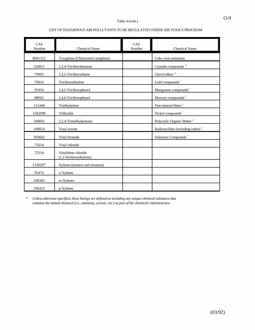
Table 4 (cont.)
LIST OF HAZARDOUS AIR POLLUTANTS TO BE REGULATED UNDER AIR TOXICS PROGRAM
O-9
(03/92)
CAS CAS Number Chemical Name Number Chemical Name
8001352 Toxaphene (Chlorinated camphene) Coke oven emissions
120821 1,2,4-Trichlorobenzene Cyanide compounds *1
79005 1,1,2-Trichloroethane Glycol ethers *2
79016 Trichloroethylene Lead compounds *
95954 2,4,5-Trichlorophenol Manganese compounds *
88062 2,4,6-Trichlorophenol Mercury compounds *
121448 Triethylamine Fine mineral fibers 3
1582098 Trifluralin Nickel compounds *
540841 2,2,4-Trimethylpentane Polycrylic Organic Matter 4
108054 Vinyl acetate Radionuclides (including radon) 5
593602 Vinyl bromide Selenium Compounds *
75014 Vinyl chloride
75354 Vinylidene chloride(1,1-Dichloroethylene)
1330207 Xylenes (isomers and mixtures)
95476 o-Xylenes
108383 m-Xylenes
106423 p-Xylenes * Unless otherwise specified, these listings are defined as including any unique chemical substance that
contains the named chemical (i.e., antimony, arsenic, etc.) as part of the chemical's infrastructure.
P-1
(03/92)
Appendix P
CONFIDENTIALITY NOTES AND DISCUSSIONS
The TSCA Notice of Inspection [Figure L-1] and Inspection Confidentiality Notice [Figure L-2] are
presented to the facility owner or agent in charge during the opening conference. These notices infor m
facility officials of their right to claim as confidential business information, any information (documents ,
physical samples, or other material) collected by the inspector.
Authority to Make Confidentiality Claims
The inspector must ascertain whether the facility official, to whom the notices were given, has th e
authority to make business confidentiality claims for the company. The facility official's signature must be
obtained at the appropriate places on the notices certifying that he does or does not have such authority.
The facility owner is assumed too always have the authority to make business confidentiality
claims. In most cases, it is expected that the agent in charge will also have such authority.
It is possible that the officials will want to consult with their attorneys (or superiors in the
case of agents in charge) regarding this issue.
If no one at the site has the authority to make business confidentiality claims, a copy of the
TSCA Inspection Confidentiality Notice and Notice and Declaration of Confidentia l
Business Information form [Figure L-3] are to be sent to the chief executive officer of the
firm within 2 days of the inspection. He will then have 7 calendar days in which to make
confidentiality claims.
Notice of Inspection (Missing)
TSCA Inspection Confidentiality Notice (Missing)
Declaration of Confidential Business Information (Missing)
P-2
(03/92)
Appendix P (cont.)
The facility official may designate a company official, in addition to the chief executiv e
officer, who should also receive a copy of the notices and any accompanying forms.
Confidentiality Discussion
Officials should be informed of the procedures and requirements that EPA must follow in handling
TSCA confidential business information. The inspector should explain that these procedures wer e
established to protect the companies subject to TSCA and c over the following points during the discussion.
Data may be claimed confidential business information during the closing conference if a
person authorized to make such claims is on-site at the facility.
It is suggested that a company official accompany the inspector during the inspection t o
facilitate designation (or avoidance, if possible) of confidential business data.
A detailed receipt for all documents, photographs, physical samples, and other material s
[Figure L-4] collected during the inspection will be issued at the closing conference.
An authorized person m ay make immediate declarations that some or all the information is
confidential business information. This is done by completing the Declaration o f
Confidential Business Information form. Each item claimed must meet all four of the criteria
shown on the TSCA Inspection Confidentiality Notice.
Receipt for Samples and Documents (Missing)
P-3
(03/92)
Appendix P (cont.)
If no authorized person is available on-site, a copy of the notices, along with the Receipt for
Samples and Documents, will be sent by certified, ret urn-receipt-requested mail to the Chief
Executive Officer of the firm and to another company official, if one has been designated.
Four copies are made of the Declaration of Confidential Information form and distributed to:
Facility owner or agent in charge
Other company official (if designated)
Document Control Officer
Inspection report
Q-1
(03/92)
Appendix Q
GLOSSARY OF TERMS AND ACRONYMS:TOXIC SUBSTANCES CONTROL ACT SECTIONS 5 AND 8
SECTION 5. New Chemicals
(Note: TSCA does not regulate chemica ls such as pesticides, drugs, cosmetics, explosives,etc., which are regulated under separate acts.)
PMN Premanufacture Notification required for all "new" TSCA chemicals(i.e., those not listed as TSCA Chemical Substances Inventory).
SNURs Significant New Use Rules require subsequent notification to EPAwhen usage/exposure of existing chemical changes.
NOC Notice of Commencement to Agency is req uired before manufacturebegins (after PMN review period has expired).
TME Test Marketing Exe mption from PMN requirement can be obtainedon application to and approval by EPA - usually subject to specificrestrictions.
LVE Low Volume Exemption from PMN requirement
PE Polymer Exemption from PMN requirement, a modified PMN
R & D Research and Development Exem ption - automatic exemption, doesnot require Agency review or approval.
Section 5(e) An administrative order l imiting the manufacture, Order processing,distribution, use and/or disposal of a chemical for which a PMN i srequired because there is insufficient information to permit ful levaluation.
Bona fide Inquiry to Agency to determine whether a chemical is on th econfidential portion of the Inventory. A Bona fide should indicatean interest or intent to commercially manufacture the subjec tchemical.
Section 5(f) An administrative order or rule prohibiting/ limiting the Order/Rulemanufacture, etc., of a chemical for which a PMN is require dbecause there is a reasonable basis to conclude that such activitie spresent an unreasonable risk to health/environment.
Q-2
(03/92)
Section 8 Existing Chemicals
PAIR Preliminary Assessment Information Rules are promulgated unde rSection 8(a) Level A and require reporting to Agency of production,uses and exposure of specific chemicals or classes of chemicals.
ITC Interagency Testing Committee designates chemicals to be listed inPAIR rules, as well as some of the chemicals in Section 8(d) rules.ITC is established under Section 4(e) of TSCA. It also recommendschemicals for inclusion in testing rules under Section 4(a).
CHEMICAL A listing compiled under Section 8(b) of TSCA of all chemical sSUBSTANCES manufactured/ processed in U .S. that were manufactured, imported,INVENTORY or processed in the period 1975-77. Chemicals for which PMN i s
submitted are added to inventory when manufacturing/processin gcommences (i.e., upon receipt of NOC). A major updating of th einventory was undertaken in 1986, and will be repeated every 4years thereafter.
CAIR Comprehensive Assessment Information Rule , a more detaile dreporting rule under Section 8(A) Level A (see PAIR
Shipbuilding and Repair Industry Sector Notebook Project
EPA/310-R-97-008
EPA Office of Compliance Sector Notebook Project:
PROFILE OF THE SHIPBUILDING AND REPAIR INDUSTRY
November 1997
Office of ComplianceOffice of Enforcement and Compliance Assurance
U.S. Environmental Protection Agency401 M St., SW (MC 2221-A)
Washington, DC 20460
Shipbuilding and Repair Industry Sector Notebook Project
Sector Notebook Project November 1997ii
This report is one in a series of volumes published by the U.S. Environmental Protection Agency(EPA) to provide information of general interest regarding environmental issues associated withspecific industrial sectors. The documents were developed under contract by Abt Associates(Cambridge, MA), Science Applications International Corporation (McLean, VA), and Booz-Allen & Hamilton, Inc. (McLean, VA). This publication may be purchased from theSuperintendent of Documents, U.S. Government Printing Office. A listing of available SectorNotebooks and document numbers is included at the end of this document.
All telephone orders should be directed to:
Superintendent of DocumentsU.S. Government Printing OfficeWashington, DC 20402(202) 512-1800FAX (202) 512-22508:00 a.m. to 4:30 p.m., EST, M-F
Using the form provided at the end of this document, all mail orders should be directed to:
U.S. Government Printing OfficeP.O. Box 371954Pittsburgh, PA 15250-7954
Complimentary volumes are available to certain groups or subscribers, such as public andacademic libraries, Federal, State, and local governments, and the media from EPA’s NationalCenter for Environmental Publications and Information at (800) 490-9198. For furtherinformation, and for answers to questions pertaining to these documents, please refer to thecontact names and numbers provided within this volume.
Electronic versions of all Sector Notebooks are available via Internet on the Enviro$en$e WorldWide Web. Downloading procedures are described in Appendix A of this document.
Cover photograph courtesy of Ingalls Shipbuilding Inc., Pascagoula, MS.
Shipbuilding and Repair Industry Sector Notebook Project
Sector Notebook Project November 1997iii
Sector Notebook Contacts
The Sector Notebooks were developed by the EPA’s Office of Compliance. Questions relating tothe Sector Notebook Project can be directed to:
Seth Heminway, Coordinator, Sector Notebook ProjectUS EPA Office of Compliance401 M St., SW (2223-A)Washington, DC 20460(202) 564-7017
Questions and comments regarding the individual documents can be directed to the appropriatespecialists listed below.
Document Number Industry Contact Phone (202)
EPA/310-R-95-001. Dry Cleaning Industry Joyce Chandler 564-7073EPA/310-R-95-002. Electronics and Computer Industry Steve Hoover 564-7007EPA/310-R-95-003. Wood Furniture and Fixtures Industry Bob Marshall 564-7021EPA/310-R-95-004. Inorganic Chemical Industry Walter DeRieux 564-7067EPA/310-R-95-005. Iron and Steel Industry Maria Malave 564-7027EPA/310-R-95-006. Lumber and Wood Products Industry Seth Heminway 564-7017EPA/310-R-95-007. Fabricated Metal Products Industry Scott Throwe 564-7013EPA/310-R-95-008. Metal Mining Industry Jane Engert 564-5021EPA/310-R-95-009. Motor Vehicle Assembly Industry Anthony Raia 564-6045EPA/310-R-95-010. Nonferrous Metals Industry Jane Engert 564-5021EPA/310-R-95-011. Non-Fuel, Non-Metal Mining Industry Robert Lischinsky 564-2628EPA/310-R-95-012. Organic Chemical Industry Walter DeRieux 564-7067EPA/310-R-95-013. Petroleum Refining Industry Tom Ripp 564-7003EPA/310-R-95-014. Printing Industry Ginger Gotliffe 564-7072EPA/310-R-95-015. Pulp and Paper Industry Maria Eisemann 564-7016EPA/310-R-95-016. Rubber and Plastic Industry Maria Malave 564-7027EPA/310-R-95-017. Stone, Clay, Glass, and Concrete Industry Scott Throwe 564-7013EPA/310-R-95-018. Transportation Equipment Cleaning Ind. Virginia Lathrop 564-7057
EPA/310-R-97-001. Air Transportation Industry Virginia Lathrop 564-7057EPA/310-R-97-002. Ground Transportation Industry Virginia Lathrop 564-7057EPA/310-R-97-003. Water Transportation Industry Virginia Lathrop 564-7057EPA/310-R-97-004. Metal Casting Industry Jane Engert 564-5021EPA/310-R-97-005. Pharmaceuticals Industry Emily Chow 564-7071EPA/310-R-97-006. Plastic Resin and Manmade Fiber Ind. Sally Sasnett 564-7074EPA/310-R-97-007. Fossil Fuel Electric Power Generation Ind. Rafael Sanchez 564-7028EPA/310-R-97-008. Shipbuilding and Repair Industry Anthony Raia 564-6045EPA/310-R-97-009. Textile Industry Belinda Breidenbach 564-7022EPA/310-R-97-010. Sector Notebook Data Refresh, 1997 Seth Heminway 564-7017
Shipbuilding and Repair Industry Sector Notebook Project
Sector Notebook Project November 1997iv
Page iv intentionally left blank.
Shipbuilding and Repair Industry Sector Notebook Project
Sector Notebook Project November 1997v
SHIPBUILDING AND REPAIR INDUSTRY(SIC 3731)
TABLE OF CONTENTS
LIST OF FIGURES . . . . . . . . . . . . . . . . . . . . . . . . . . . . . . . . . . . . . . . . . . . . . . . . . . . . . . . . . vii
LIST OF TABLES . . . . . . . . . . . . . . . . . . . . . . . . . . . . . . . . . . . . . . . . . . . . . . . . . . . . . . . . . vii
LIST OF ACRONYMS . . . . . . . . . . . . . . . . . . . . . . . . . . . . . . . . . . . . . . . . . . . . . . . . . . . . . viii
I. INTRODUCTION TO THE SECTOR NOTEBOOK PROJECT . . . . . . . . . . . . . . . . . . . . . 1A. Summary of the Sector Notebook Project . . . . . . . . . . . . . . . . . . . . . . . . . . . . . . . . 1B. Additional Information . . . . . . . . . . . . . . . . . . . . . . . . . . . . . . . . . . . . . . . . . . . . . . . 2
II. INTRODUCTION TO THE SHIPBUILDING AND REPAIR INDUSTRY . . . . . . . . . . . . 3A. Introduction, Background, and Scope of the Notebook . . . . . . . . . . . . . . . . . . . . . . 3B. Characterization of the Shipbuilding and Repair Industry . . . . . . . . . . . . . . . . . . . . . 3
1. Product Characterization . . . . . . . . . . . . . . . . . . . . . . . . . . . . . . . . . . . . . . . . 32. Industry Size and Geographic Distribution . . . . . . . . . . . . . . . . . . . . . . . . . . . 63. Economic Trends . . . . . . . . . . . . . . . . . . . . . . . . . . . . . . . . . . . . . . . . . . . . . . 9
III. INDUSTRIAL PROCESS DESCRIPTION . . . . . . . . . . . . . . . . . . . . . . . . . . . . . . . . . . . 13A. Industrial Processes in the Shipbuilding and Repair Industry . . . . . . . . . . . . . . . . . . 13
1. Shipyard Layout . . . . . . . . . . . . . . . . . . . . . . . . . . . . . . . . . . . . . . . . . . . . . 132. Docking and Launching Facilities . . . . . . . . . . . . . . . . . . . . . . . . . . . . . . . . . 143. Ship Construction Processes . . . . . . . . . . . . . . . . . . . . . . . . . . . . . . . . . . . . 164. Major Production Facilities . . . . . . . . . . . . . . . . . . . . . . . . . . . . . . . . . . . . . 185. Welding . . . . . . . . . . . . . . . . . . . . . . . . . . . . . . . . . . . . . . . . . . . . . . . . . . . . 196. Ship Repairing Processes . . . . . . . . . . . . . . . . . . . . . . . . . . . . . . . . . . . . . . . 207. Support Shops and Services . . . . . . . . . . . . . . . . . . . . . . . . . . . . . . . . . . . . . 218. Solvent Cleaning and Degreasing . . . . . . . . . . . . . . . . . . . . . . . . . . . . . . . . . 239. Surface Preparation . . . . . . . . . . . . . . . . . . . . . . . . . . . . . . . . . . . . . . . . . . . 2410. Painting Processes . . . . . . . . . . . . . . . . . . . . . . . . . . . . . . . . . . . . . . . . . . . 28
B. Raw Material Inputs and Pollutant Outputs . . . . . . . . . . . . . . . . . . . . . . . . . . . . . . . 331. Surface Preparation . . . . . . . . . . . . . . . . . . . . . . . . . . . . . . . . . . . . . . . . . . . 332. Painting . . . . . . . . . . . . . . . . . . . . . . . . . . . . . . . . . . . . . . . . . . . . . . . . . . . . 343. Metal Plating and Surface Finishing . . . . . . . . . . . . . . . . . . . . . . . . . . . . . . . 354. Fiberglass Reinforced Construction . . . . . . . . . . . . . . . . . . . . . . . . . . . . . . . 365. Machining and Metalworking . . . . . . . . . . . . . . . . . . . . . . . . . . . . . . . . . . . 366. Solvent Cleaning and Degreasing . . . . . . . . . . . . . . . . . . . . . . . . . . . . . . . . . 37
C. Management of Chemicals in Wastestream . . . . . . . . . . . . . . . . . . . . . . . . . . . . . . . 40
Shipbuilding and Repair Industry Sector Notebook Project
Sector Notebook Project November 1997vi
IV. CHEMICAL RELEASE AND TRANSFER PROFILE . . . . . . . . . . . . . . . . . . . . . . . . . . 43A. EPA Toxic Release Inventory for the Shipbuilding and Repair Industry . . . . . . . . . 47B. Summary of Selected Chemicals Released . . . . . . . . . . . . . . . . . . . . . . . . . . . . . . . . 52C. Other Data Sources . . . . . . . . . . . . . . . . . . . . . . . . . . . . . . . . . . . . . . . . . . . . . . . . 57D. Comparison of Toxic Release Inventory Between Selected Industries . . . . . . . . . . . 59
V. POLLUTION PREVENTION OPPORTUNITIES . . . . . . . . . . . . . . . . . . . . . . . . . . . . . . 63A. Surface Preparation . . . . . . . . . . . . . . . . . . . . . . . . . . . . . . . . . . . . . . . . . . . . . . . . 64B. Painting and Coating . . . . . . . . . . . . . . . . . . . . . . . . . . . . . . . . . . . . . . . . . . . . . . . 65
1. Application Equipment . . . . . . . . . . . . . . . . . . . . . . . . . . . . . . . . . . . . . . . . 652. Alternative Coatings . . . . . . . . . . . . . . . . . . . . . . . . . . . . . . . . . . . . . . . . . . 693. Good Operating Practices . . . . . . . . . . . . . . . . . . . . . . . . . . . . . . . . . . . . . . 70
C. Metal Plating and Surface Finishing . . . . . . . . . . . . . . . . . . . . . . . . . . . . . . . . . . . . 71D. Fiberglass Reinforced Construction . . . . . . . . . . . . . . . . . . . . . . . . . . . . . . . . . . . . 72E. Solvent Cleaning and Degreasing . . . . . . . . . . . . . . . . . . . . . . . . . . . . . . . . . . . . . . . 73F. Machining and Metalworking . . . . . . . . . . . . . . . . . . . . . . . . . . . . . . . . . . . . . . . . . 78
VI. SUMMARY OF FEDERAL STATUTES AND REGULATIONS . . . . . . . . . . . . . . . . . . 81A. General Description of Major Statutes . . . . . . . . . . . . . . . . . . . . . . . . . . . . . . . . . . 81B. Industry Specific Requirements . . . . . . . . . . . . . . . . . . . . . . . . . . . . . . . . . . . . . . . . 93C. Pending and Proposed Regulatory Requirements . . . . . . . . . . . . . . . . . . . . . . . . . . 97
VII. COMPLIANCE AND ENFORCEMENT HISTORY . . . . . . . . . . . . . . . . . . . . . . . . . . . 99A. Shipbuilding and Repair Industry Compliance History . . . . . . . . . . . . . . . . . . . . . . 103B. Comparison of Enforcement and Compliance Activity Between Selected Industries
. . . . . . . . . . . . . . . . . . . . . . . . . . . . . . . . . . . . . . . . . . . . . . . . . . . . . . . . . . . 105C. Review of Major Legal Actions . . . . . . . . . . . . . . . . . . . . . . . . . . . . . . . . . . . . . . 110
1. Review of Major Cases . . . . . . . . . . . . . . . . . . . . . . . . . . . . . . . . . . . . . . . . 1102. Supplementary Environmental Projects (SEPs) . . . . . . . . . . . . . . . . . . . . . . 110
VIII. COMPLIANCE ASSURANCE ACTIVITIES AND INITIATIVES . . . . . . . . . . . . . . 111A. Sector-related Environmental Programs and Activities . . . . . . . . . . . . . . . . . . . . . . 111B. EPA Voluntary Programs . . . . . . . . . . . . . . . . . . . . . . . . . . . . . . . . . . . . . . . . . . . 114C. Trade Associations . . . . . . . . . . . . . . . . . . . . . . . . . . . . . . . . . . . . . . . . . . . . . . . . 120
IX. CONTACTS/ACKNOWLEDGMENTS/RESOURCE MATERIALS . . . . . . . . . . . . . . . 123
Appendix A: Instructions for downloading this notebook . . . . . . . . . . . . . . . . . . . . . . . . . . . . A-1
Shipbuilding and Repair Industry Sector Notebook Project
Sector Notebook Project November 1997vii
LIST OF FIGURES
Figure 1: Profiles of Ship Types . . . . . . . . . . . . . . . . . . . . . . . . . . . . . . . . . . . . . . . . . . . . . . . . . 5Figure 2: Geographic Distribution of Shipyards . . . . . . . . . . . . . . . . . . . . . . . . . . . . . . . . . . . . . 8Figure 3: Example Shipyard Layout . . . . . . . . . . . . . . . . . . . . . . . . . . . . . . . . . . . . . . . . . . . . . 15Figure 4: General Ship Manufacturing Levels . . . . . . . . . . . . . . . . . . . . . . . . . . . . . . . . . . . . . . 17Figure 5: Typical Pickling Tank Arrangement . . . . . . . . . . . . . . . . . . . . . . . . . . . . . . . . . . . . . 27Figure 6: Summary of TRI Releases and Transfers by Industry . . . . . . . . . . . . . . . . . . . . . . . . . 60
LIST OF TABLES
Table 1: Facility Size Distribution for the Shipbuilding and Repair Industry . . . . . . . . . . . . . . . . 7Table 2: Top U.S. Companies with Shipbuilding and Repair Operations . . . . . . . . . . . . . . . . . . . 9Table 3: Material Inputs and Potential Pollutant Outputs for the Shipbuilding and Repair Industry . . . . . . . . . . . . . . . . . . . . . . . . . . . . . . . . . . . . . . . . 39Table 4: Source Reduction and Recycling Activity for Shipyards . . . . . . . . . . . . . . . . . . . . . . . 41Table 5: 1995 TRI Releases for Shipbuilding and Repair Facilities . . . . . . . . . . . . . . . . . . . . . . 49Table 6: 1995 TRI Transfers for Shipbuilding and Repair Facilities . . . . . . . . . . . . . . . . . . . . . 50Table 7:Top 10 TRI Releasing Shipbuilding and Repair Facilities Reporting Only SIC 3731 . . 51Table 8: Top 10 TRI Releasing Facilities Reporting Only SIC 3731
or SIC 3731 and Other SIC codes . . . . . . . . . . . . . . . . . . . . . . . . . . . . . . . . . . . . . . 52Table 9: Air Pollutant Releases (tons/year) . . . . . . . . . . . . . . . . . . . . . . . . . . . . . . . . . . . . . . . . 58Table 10: Toxics Release Inventory Data for Selected Industries . . . . . . . . . . . . . . . . . . . . . . . 61Table 11: Five-Year Enforcement and Compliance Summary for the
Shipbuilding and Repair Industry . . . . . . . . . . . . . . . . . . . . . . . . . . . . . . . . . . . . . . 103Table 12: Five-Year Enforcement and Compliance Summary for Selected Industries . . . . . . . 106Table 13: One-Year Enforcement and Compliance Summary for Selected Industries . . . . . . . 107Table 14: Five-Year Inspection and Enforcement Summary by Statute for Selected Industries 108Table 15: One-Year Inspection and Enforcement Summary by Statute for Selected Industries 109Table 16: Shipbuilding and Repair Industry Participation in the 33/50 Program . . . . . . . . . . . 115
Shipbuilding and Repair Industry Sector Notebook Project
Sector Notebook Project November 1997viii
LIST OF ACRONYMS
AFS - AIRS Facility Subsystem (CAA database)AIRS - Aerometric Information Retrieval System (CAA database)BIFs - Boilers and Industrial Furnaces (RCRA)BOD - Biochemical Oxygen Demand CAA - Clean Air ActCAAA - Clean Air Act Amendments of 1990CERCLA - Comprehensive Environmental Response, Compensation, and Liability ActCERCLIS - CERCLA Information SystemCFCs - ChlorofluorocarbonsCO - Carbon Monoxide COD - Chemical Oxygen Demand CSI - Common Sense Initiative CWA - Clean Water ActD&B - Dun and Bradstreet Marketing IndexELP - Environmental Leadership Program EPA - United States Environmental Protection AgencyEPCRA - Emergency Planning and Community Right-to-Know Act FIFRA - Federal Insecticide, Fungicide, and Rodenticide ActFINDS - Facility Indexing SystemHAPs - Hazardous Air Pollutants (CAA)HSDB - Hazardous Substances Data Bank IDEA - Integrated Data for Enforcement AnalysisLDR - Land Disposal Restrictions (RCRA)LEPCs - Local Emergency Planning Committees MACT - Maximum Achievable Control Technology (CAA)MCLGs - Maximum Contaminant Level Goals MCLs - Maximum Contaminant Levels MEK - Methyl Ethyl KetoneMSDSs - Material Safety Data Sheets NAAQS - National Ambient Air Quality Standards (CAA)NAFTA - North American Free Trade Agreement NCDB - National Compliance Database (for TSCA, FIFRA, EPCRA)NCP - National Oil and Hazardous Substances Pollution Contingency Plan NEIC - National Enforcement Investigation Center NESHAP - National Emission Standards for Hazardous Air PollutantsNO - Nitrogen Dioxide2
NOV - Notice of Violation NO - Nitrogen OxidesX
NPDES - National Pollution Discharge Elimination System (CWA)NPL - National Priorities List NRC - National Response Center
Shipbuilding and Repair Industry Sector Notebook Project
Sector Notebook Project November 1997ix
NSPS - New Source Performance Standards (CAA)OAR - Office of Air and RadiationOECA - Office of Enforcement and Compliance AssuranceOPA - Oil Pollution ActOPPTS - Office of Prevention, Pesticides, and Toxic SubstancesOSHA - Occupational Safety and Health Administration OSW - Office of Solid WasteOSWER - Office of Solid Waste and Emergency ResponseOW - Office of WaterP2 - Pollution PreventionPCS - Permit Compliance System (CWA Database)POTW - Publicly Owned Treatments Works RCRA - Resource Conservation and Recovery ActRCRIS - RCRA Information SystemSARA - Superfund Amendments and Reauthorization Act SDWA - Safe Drinking Water ActSEPs - Supplementary Environmental Projects SERCs - State Emergency Response Commissions SIC - Standard Industrial Classification SO - Sulfur Dioxide 2
SO - Sulfur OxidesX
TOC - Total Organic Carbon TRI - Toxic Release InventoryTRIS - Toxic Release Inventory System TCRIS - Toxic Chemical Release Inventory SystemTSCA - Toxic Substances Control ActTSS - Total Suspended Solids UIC - Underground Injection Control (SDWA)UST - Underground Storage Tanks (RCRA)VOCs - Volatile Organic Compounds
Shipbuilding and Repair Industry Sector Notebook Project
Sector Notebook Project November 1997x
Page x intentionally left blank.
Shipbuilding and Repair Industry Sector Notebook Project
Sector Notebook Project November 19971
SHIPBUILDING AND REPAIR INDUSTRY(SIC 3731)
I. INTRODUCTION TO THE SECTOR NOTEBOOK PROJECT
I.A. Summary of the Sector Notebook Project
Integrated environmental policies based upon comprehensive analysis of air,water, and land po llution are a logical supplement to traditional single-mediaapproaches to en vironmental protection. Environmental regulatory agenciesare beginning to embrace comprehensive, multi-statute solutions to facilit ypermitting, enforcement and compliance assurance, education/ outreach ,research, and regulatory development issues. The ce ntral concepts driving thenew policy direction are that pollutant relea ses to each environmental medium(air, water, and land) affect each other, and that environmental strategies mustactively identify and address these in ter-relationships by designing policies forthe "whole" facility. One way to achieve a whole facility focus is to desig nenvironmental policies for similar industrial facilities. By doing so ,environmental concerns that are common to the manufacturing of simila rproducts can be addressed in a comprehensive manner. Recognition of th eneed to develop the industrial “sector-b ased” approach within the EPA Officeof Compliance led to the creation of this document.
The Sector Notebook Project was originally initiated by the Office o fCompliance within the Office of Enforcement and Compliance Assuranc e(OECA) to provide its staff and managers with summary information fo reighteen specific industrial sectors. As other E PA offices, states, the regulatedcommunity, environmental groups, and the public became interested in thi sproject, the scope of the original project was expanded to its current form .The ability to design comprehensive, comm on sense environmental protectionmeasures for specific industries is dependent on knowledge of several inter-related topics. For the purposes of this project, the key elements chosen forinclusion are: general industry information (economic and geographic); adescription of industrial processes; pollution outputs; pollution preventio nopportunities; Federal statutory and regulatory framework; complianc ehistory; and a description of partnerships that have been formed betwee nregulatory agencies, the regulated community, and the public.
For any given industry, each topic listed above could alone be the subject ofa lengthy volume. However, in order to produce a managea ble document, thisproject focuses on providing summary information for each topic. Thi sformat provides the reader with a synopsis of each issu e, and references wheremore in-depth information is available. Text within each profile wa sresearched from a variety of sources, and was usually condensed from moredetailed sources pertaining to specific topics. Thi s approach allows for a widecoverage of activities that can be further explored based upon the citation s
Shipbuilding and Repair Industry Sector Notebook Project
Sector Notebook Project November 19972
and references listed at th e end of this profile. As a check on the informationincluded, each notebook went through an external revi ew process. The Officeof Compliance appreciates the efforts of all those that participated in thi sprocess and enabled us to develop more complete, accurate and up-to-dat esummaries. Many of those who revie wed this notebook are listed as contactsin Section IX and may be sources of additional information. The individualsand groups on this list do not necessarily concur with al l statements within thisnotebook.
I.B. Additional Information
Providing Comments
OECA’s Office of Compliance plans to periodically review and update th enotebooks and will make these updates available both in hard copy an delectronically. If you have any comments on the existing notebook, or if youwould like to provide additional information, please send a hard copy an dcomputer disk to the EPA Office of Compliance, Sector Notebook Project,401 M St., SW (2223-A), Washington, DC 20460. Comments can also b euploaded to the Enviro$en$e Worl d Wide Web for general access to all usersof the system. Follow instructions in Appendix A for accessing this system.Once you have logged in, procedures for uploading text are available from theon-line Enviro$en$e Help System.
Adapting Notebooks to Particular Needs
The scope of the industry sector descri bed in this notebook approximates thenational occurrence of facility types within the sector. In many instances ,industries within specific geographic regions or states may have uniqu echaracteristics that are not fully captured in these profiles. The Office o fCompliance encourages state and local environmental agencies and othe rgroups to supplement or re-package the informati on included in this notebookto include more specific industrial and regulatory information that may b eavailable. Additionally, interested states may want to supplement th e"Summary of Applicable Federal S tatutes and Regulations" section with stateand local requirements. Compliance or technical assistance providers ma yalso want to develop the "Pollution Prevention" section in more detail. Pleasecontact the appropriate s pecialist listed on the opening page of this notebookif your office is interested in assisting us in the further development of th einformation or policies addressed within this volume. If you are interested inassisting in the devel opment of new notebooks for sectors not covered in theoriginal eighteen, please contact the Office of Compliance at 202-564-2395.
Shipbuilding and Repair Industry Introduction
Sector Notebook Project November 19973
II. INTRODUCTION TO THE SHIPBUILDING AND REPAIR INDUSTRY
This section provides background information on the size, geographi cdistribution, employment, production, sales, and economic condition of th eship building and repair industry. Facilities describ ed within this document aredescribed in terms of their Standard Industrial Classification (SIC) codes.
II.A. Introduction, Background, and Scope of the Notebook
The shipbuilding and repair industry builds and repairs ships, barges, and otherlarge vessels, whether self-propelled or towed by other craft. The industr yalso includes the conversion and alteration of ships and the manufacture o foffshore oil and gas well drilling and production platforms. The shipbuildingand repair indus try described in this notebook is categorized by the Office ofManagement and Budget (OMB) u nder the Standard Industrial Classification(SIC) code 3731. This not ebook does not cover the related sector SIC 3732Boat Building and Repairing. The boat building and repair industry i sengaged in the manufacturing and repairing of smaller non-ocean goin gvessels primarily used for recreation, fishing, and personnel transport. OMBis in the process of changing the SIC code system to a system based on similarproduction processes called the North American Industrial Classificatio nSystem (NAICS). (In the NAIC system, shipbuilding and repair facilities areall classified as NAIC 336611.)
II.B. Characterization of the Shipbuilding and Repair Industry
Shipyards, or facilities that build and/or repair ships, operate on a job basis.With the excepti on of about nine U.S. Navy owned shipyards (which are notincluded in SIC 3731), the U.S. shipbuilding and repair industry is privatelyowned. Unlike most other industries, each year only a small number o fvaluable orders are received that often take years to fill. Orders for ships andship repairs are primarily placed by companies or the federal government .Companies that place orders often include commercial shipping companies ,passenger and cruise companies, ferry companies, petrochemical companies,commercial fishing companies, and towing and tugboat companies. Th eprincipal federal government agencies placing shipbuilding and repair ordersinclude the Naval Sea S ystems Command, the Military Sealift Command, theArmy Corps of Engineers, the U.S. Coast Guard, the National Oceanic andAtmospheric Administration, the National Science Foundation, and th eMaritime Administration.
II.B.1. Product Characterization
Shipyards are often categorized into a fe w basic subdivisions either by type ofoperations (shipbuilding or ship repairing), by type of ship (commercial o rmilitary), and shipbuilding or repairing capacity (first-tier or second-tier) .
Shipbuilding and Repair Industry Introduction
Sector Notebook Project November 19974
Ships themselves are often classified by their basic dimensions, weigh t(displacement), load-carrying capacity (deadweight ), or their intended service.In the U.S., there are considerable differences between shipyard operation swhen constructing ships for commercial purposes and whe n constructing shipsfor the military.
Commercial Ships
An important difference between commercial ships and military ships is thatthe commercial ship market is much more cost competitive. Unlike th emilitary market, the commercial ship market must also compet einternationally. The cost of building and maintaining a ship must be lo wenough such that the owners can make a reasonable profit. This has asignificant impact on the manner in which commercial ships are built an drepaired. The intense global competition in this industry is the main reaso nthat since World War II, U.S. shipyards have produced relatively fe wcommercial ships. In t his regard, since 1981 the U.S. shipyards received lessthan one percent of all commercia l orders for large ocean going vessels in theworld, and no commercial orders for large ocean going cruise ships (ASA ,1997).
Commercial ships can be subdivided into a number of classes based on theirintended use. Comme rcial ship classes include dry cargo ships, tankers, bulkcarriers, passenger ships, fishing vessels , industrial vessels, and others (Storchet al., 1995). Dry cargo ships include break bulk, container, and roll-on/roll-off types. Profiles of a number of ship types are shown in Figure 1.
Military Ships
Military ship orders have been the mainstay of the industry for many years .The military ship market differs fro m the commercial market in that the majormarket drivers are agency budgets as set by government policy.
The military ship market can be divided into combatant ships and ships thatare ordered by the government, but are built and maintained to commercia lstandards rather than military standards. (Storch et al., 1995) Combatan tships are primarily ordered by the U.S. Navy and include surface combatants,submarines, aircraft carriers, and auxiliaries. Government owned non -combatant ships are mainly purchased by the Maritime Administration’ sNational Defense Reserve Fleet (NDRF) and the Navy’s Military Sealif tCommand (MSC). Other govern ment agencies that purchase non-combatantships are the Army Corp of Engineers, National Oceanic and Atmospheri cAdministration, and the National Science Foundation. Such ships ofte ninclude cargo ships, transport ships, roll on/roll off ships, crane ships, tankers,patrol ships, and ice breakers.
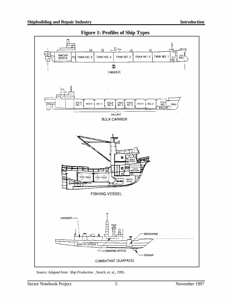
Shipbuilding and Repair Industry Introduction
Sector Notebook Project November 19975
Source: Adapted from Ship Production , Storch, et. al., 1995.
Figure 1: Profiles of Ship Types
Shipbuilding and Repair Industry Introduction
Sector Notebook Project November 19976
Ship Repairing
Ship repair operations include repainting, overhauls, ship conversions, an dalterations. Alm ost all shipyards that construct new ships also do major shiprepairs. In addi tion, about 200 shipyards concentrate solely on ship repairingand do not have the necessary facilities to construct ships (Storch et. al. ,1995). Only about 31 shipyards have “major dry-docking facilities” capableof removing ships over 122 meters in length from the water (MARAD, 1995).Dry-docking facilities, or “full service” repair yards, allow repairs an dmaintenance below a ship’s water line. The remaining repair yards can eitherdry-dock vessels under 122 meters or have no dry-docking facilities .Shipyards with no dry-docking faciliti es, called topside yards, perform above-water ship and barge repairs. Suc h facilities generally employ fewer than 100people and are often capable of transporting w orkers and materials to the ship(Storch et al., 1995).
First and Second-Tier Shipyards
U.S. shipyards are also classified by MARAD as either first-tier shipyards orsecond-tier shipyards. First-tier shipyards make up the “U.S. majo rshipbuilding base” (MSB). As defined by MARAD and the Department o fTransportation in “Report on Survey of U.S. Shipbuilding and Repai rFacilities,” 1995, the MSB is compris ed of privately owned shipyards that areopen and have at least one shipbuilding position capable of accommodatinga vessel of 122 meters (383 feet) or more. With few exceptions, thes eshipyards are also major repair facilities with drydocking capabilities (U.S .Industrial Outlook, 1994). In 1996 there were 16 of these major shipbuildingfacilities in the U.S.
Second-tier shipyards are comprised of the many small and medium-siz eshipyards that construct and repair sma ller vessels (under 122 meters) such asmilitary and non-military patrol boats, fire and rescue vessels, casino boats ,water taxis, tug and towboats, off-shore crew and supply boats, ferries, fishingboats, and shallow draft barges (MARAD, 1996). A number of second-tie rshipyards are also able to make topside repairs to ships over 122 meters i nlength.
II.B.2. Industry Size and Geographic Distribution
According to the 1992 Census of Manufacturers data (the most recent Censusdata available), there were approximately 598 shi pbuilding and repairing yardsunder SIC code 3731. The payroll for this year totaled $3.6 billion for aworkforce of 118,000 employees, and value of shipments totaled $10. 6billion. Based on the Census of Manufacture rs data, the industry is very laborintensive. The value of shipments per employee (a measure of labo rintensiveness) is $90,000, which is about one third that of the stee l
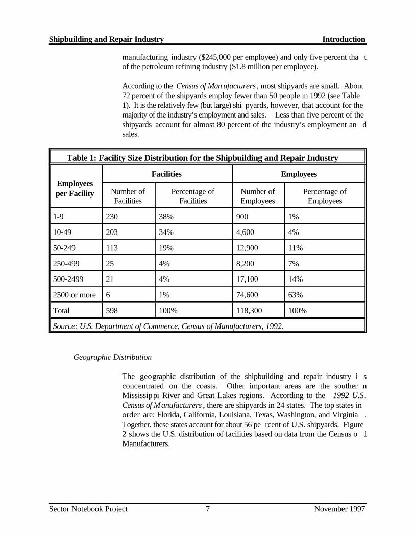
Shipbuilding and Repair Industry Introduction
Sector Notebook Project November 19977
manufacturing industry ($245,000 per employee) and only five percent tha tof the petroleum refining industry ($1.8 million per employee).
According to the Census of Man ufacturers , most shipyards are small. About72 percent of the shipyards employ fewer than 50 people in 1992 (see Table1). It is the relatively few (but large) shi pyards, however, that account for themajority of the industry’s employment and sales. Less than five percent of theshipyards account for almost 80 percent of the industry’s employment an dsales.
Table 1: Facility Size Distribution for the Shipbuilding and Repair Industry
Employeesper Facility
Facilities Employees
Number of Percentage of Number of Percentage ofFacilities Facilities Employees Employees
1-9 230 38% 900 1%
10-49 203 34% 4,600 4%
50-249 113 19% 12,900 11%
250-499 25 4% 8,200 7%
500-2499 21 4% 17,100 14%
2500 or more 6 1% 74,600 63%
Total 598 100% 118,300 100%
Source: U.S. Department of Commerce, Census of Manufacturers, 1992.
Geographic Distribution
The geographic distribution of the shipbuilding and repair industry i sconcentrated on the coasts. Other important areas are the souther nMississippi River and Great Lakes regions. According to the 1992 U.S.Census of Manufacturers , there are shipyards in 24 states. The top states inorder are: Florida, California, Louisiana, Texas, Washington, and Virginia .Together, these states account for about 56 pe rcent of U.S. shipyards. Figure2 shows the U.S. distribution of facilities based on data from the Census o fManufacturers.
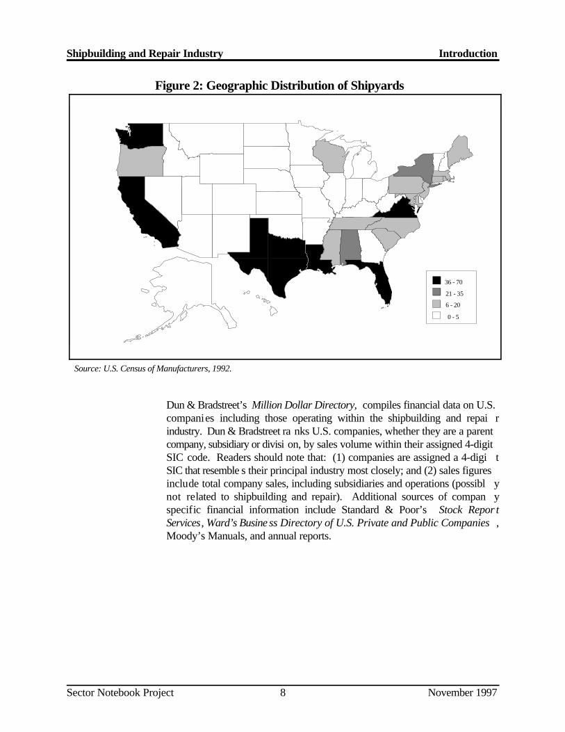
0 - 5
36 - 70
21 - 35
6 - 20
Shipbuilding and Repair Industry Introduction
Sector Notebook Project November 19978
Figure 2: Geographic Distribution of Shipyards
Source: U.S. Census of Manufacturers, 1992.
Dun & Bradstreet’s Million Dollar Directory, compiles financial data on U.S.companies including those operating within the shipbuilding and repai rindustry. Dun & Bradstreet ra nks U.S. companies, whether they are a parentcompany, subsidiary or divisi on, by sales volume within their assigned 4-digitSIC code. Readers should note that: (1) companies are assigned a 4-digi tSIC that resemble s their principal industry most closely; and (2) sales figuresinclude total company sales, including subsidiaries and operations (possibl ynot related to shipbuilding and repair). Additional sources of compan yspecific financial information include Standard & Poor’s Stock Repor tServices, Ward’s Busine ss Directory of U.S. Private and Public Companies ,Moody’s Manuals, and annual reports.
Shipbuilding and Repair Industry Introduction
Sector Notebook Project November 19979
Table 2: Top U.S. Companies with Shipbuilding and Repair Operations
Rank Company (millions of dollars)a b1996 Sales
1 Newport News Shipbuilding and Dry Dock Co. 1,756Newport News, VA
2 Ingalls Shipbuilding Inc. - Pascagoula, MS 1,125
3 General Dynamics Corp. (Electric Boat) - Groton, CT 980
4 Bath Iron Works Corp. - Bath, ME 850
5 Avondale Industries Inc., Shipyards Division 576New Orleans, LA
6 National Steel and Shipbuilding Co. (NASSCO) 500San Diego, CA
7 Trinity Marine Group - Gulfport, MS 400
8 Norfolk Shipbuilding and Drydock Corp. - Norfolk, VA 212
9 American Commercial Marine Service Co. - 166Jeffersonville, IN
10 Atlantic Marine - Jacksonville, FL 121
Note: Not all sales can be attributed to the companies’ shipbuilding and repair operations.a
Companies shown listed SIC 3731. b
Source: Dunn & Bradstreet’s Million Dollar Directory - 1996.
II.B.3. Economic Trends
General Economic Health
In general, the U.S. shipbuilding and repair industry is in a depressed state .At its height in the mid-1970s, the industry held a significant portion of th einternational commercial market while maintaining its ability to supply al lmilitary orders. Since then, new ship constructio n, the number of shipbuildingand repair yards, and overall industry employment have decreased sharply .The decline has been especially severe in the construction of commercia lvessels at first tier shipya rds which fell from about 77 ships (1,000 gross tonsor more) per year in the mid-1970s to onl y about eight ships total through thelate 1980s and early 1990s. In the 1980s, the industry’s loss of th ecommercial market share was somewhat offset by a substantial increase i nmilitary ship orders. Following the naval expansion, however, the industr y
Shipbuilding and Repair Industry Introduction
Sector Notebook Project November 199710
entered the 1990 s with a much smaller military market and a negligible shareof the commercial market.
The second tier shipyards and the ship repairing segment of the industry hasalso suffered in recent decades; however, its decline has not been as drastic.The second tier shipyards, comprised of small an d medium size facilities, wereable to keep much of their m ainly commercial market share. These shipyardsbuild vessels used on t he inland and coastal waterways which by law must bebuilt in the U.S.
The U.S. shipbuilding and repairing industry’s loss of the commercia lshipbuilding market has been attribute d to a number of factors. First, a worldwide shipbuilding boom in the 1970s created a large quantity of surplu stonnage which suppressed demand for years. Another significant facto rreducing U.S. shipbuilding and repair industry’s ability to compet einternationally are the su bstantial subsidies that many nations provide to theirdomestic shipbuilding and repair industri es. Also, until 1980, over 40 percentof U.S.-built merchant ships received Construction Differential Subsidie s(CDS) based on the difference between foreign and domestic shipbuildin gcosts. The program was eliminated in 1981, further reducing the industry’ scompetitiveness.
Another trend in the indu stry has been a movement toward consolidation. Inrecent years many shipyards have been closed or purchased by larger shi pbuilding and repair companies.
Government Influences
The U.S. shipbuilding and repair industry is highly dependent on the FederalGovernment, its primary market, for its continued exi stence. Direct purchasesof military ships and military ship repair services by the Federal Governmentaccount for about 80 percent of the industry’s sales (Census o fManufacturers, 1992). In addition, the industry receives a small amount o fsupport through a few federal tax incentives and financing assistanc eprograms.
MARAD provides assistance to U.S. ship owners through the Federal Shi pMortgage Insurance (Title XI) and Capital Construction Fund programs .Under Title XI, the Federal Government guarantees repayment of privat esector mortgage obligations for operators that purchase ships from U.S .shipyards. Although the Capital Construction Fund has not been funded i nrecent years, in the past it has allowed operators to establish tax-deferre dfunds for procuring new or reconstructed vessels from U.S. shipyards (U.S.Industrial Outlook, 19 94). Another program, MARITECH, is jointly fundedby the Federal Government and industry and is administered by th eDepartment of Defense’s Advanced Research Projects Agency (ARPA), i n
Shipbuilding and Repair Industry Introduction
Sector Notebook Project November 199711
collaboration with MARAD. MARITECH provides matching Governmen tfunds to encourage the shipbuilding industry to direct and lead in th edevelopment and application of advanced technology to improve it scompetitiveness and to p reserve its industrial base. (For more information onMARITECH, see Section VIII.A.)
Such outside support is not unique to the U.S. Worldwide, many nation sprovide substantial subsidies to their shipbuilding and repair industries. Thegovernments of most trading nations support their domestic industries becausethey believe that it is in their best interest economically and militarily .Maintaining a shipbuilding industrial base helps to sa feguard a nation’s controlover getting it s products to foreign markets, and ensures that it will have themeans to replace its merch ant or naval fleets in a time of national emergency.As a result of these external influences, the industry does not behav eaccording to the simple economic supply and demand model. Rather, th epolicies of national governments in conjunction with economic forces dictateeconomic activity in this sector.
Like many other nations, the U.S. has a policy of maintaining a shipbuildingand repair industrial base that can be expanded in time of war (Storch, et al.,1995). National policy, therefore, will continue to be the primary facto rinfluencing the industry’s economic trends in the U.S.
Domestic Market
The military still is, and will continue to be, the primar y source of work for theindustry. However, the Navy’s new ship procurement has sharply decline dsince the accelerated Navy ship construction in the 1980s. This work i sexpected to continue to decline at least through the remainder of the 1990s.Some industry analysts predict th at a number of the first tier shipyards, whichfill most of the military orders, will close in coming years.
While military shipbuilding is on the decline, the forecast for the commercialsector is more promising. Domestic demand for commercial shipbuilding andrepair has increased dramatically in recent years and is expected to continueto increase throughout the 1990s. There have been significant increases i nbarge construction in recent years. In 1996, 1,070 hopper barges wer edelivered by U.S. shi pyards, more than double the number delivered in 1995.This number is expected to grow to over 1,500 in 1997. Demand is als oexpected to be particularly high for tankers; especially for new double-hul ltankers in response to the 1990 Oil Pollution Act requirements.
Shipbuilding and Repair Industry Introduction
Sector Notebook Project November 199712
International Market
Currently, the U.S. holds less than one half of one percen t of the world marketshare of commercial shipbuilding and repair. South Kor ea and Japan currentlydominate the world market. Each holds about 30 percent of the gros stonnage of merchant ships on order. Germany, Poland, Italy, and China eachhold between four and five percent of the commercial market. However, anumber of major commercial ship orders were received by fi rst and second tiershipyards in 1995 and 1996. The c hief driving forces for this increase in U.S.commercial ship production is a general increase in worldwide deman dstemming from an aging merchant fleet and an improving global economy .The elevated demand is expected to continue over the next three to five years.
Through the OECD in December 1994, an agreement was reached by th eCommission of the European Co mmunities, and the Governments of Finland,Japan, South Korea, Norway, Sweden and the United States to establish morenormal competitive condition s in the shipbuilding industry. The agreement isexpected to remove government support and unfair pricing practices in th eindustry. If and when this agreement is implemented, it is expected to havea positive impact on the world market by discouraging “ship dumping ”practices that are believed to have been damaging shipbuilders. It is hope dthat the agreement will also bring to light the actual economic advantage andcompetitiveness of the various countries and individual ship builders. I naddition, the shipowners will no longer be able to buy ships at subsidized ordumped prices reducing the likelihood of speculative buying.
Recognizing the unique need for the Administration, Congress and th eshipbuilding industry to work together in order for the U.S. to becom ecompeti tive once again in the international shipbuilding market, Presiden tClinton submitted a Report to Congress entitled “Strengthening America’ sShipyards: A Plan for Competing in the Inter national Market.” In that report,the President outlined a number of steps to be taken “to ensure a successfultransition to a com petitive industry in a truly competitive marketplace.” TheAdministration’s five step plan included:
Ensuring Fair International CompetitionImproving CompetitivenessEliminating Unnecessary Government RegulationFinancing Ship Sales Through Title XI Loan Guarantees, andAssisting International Marketing.
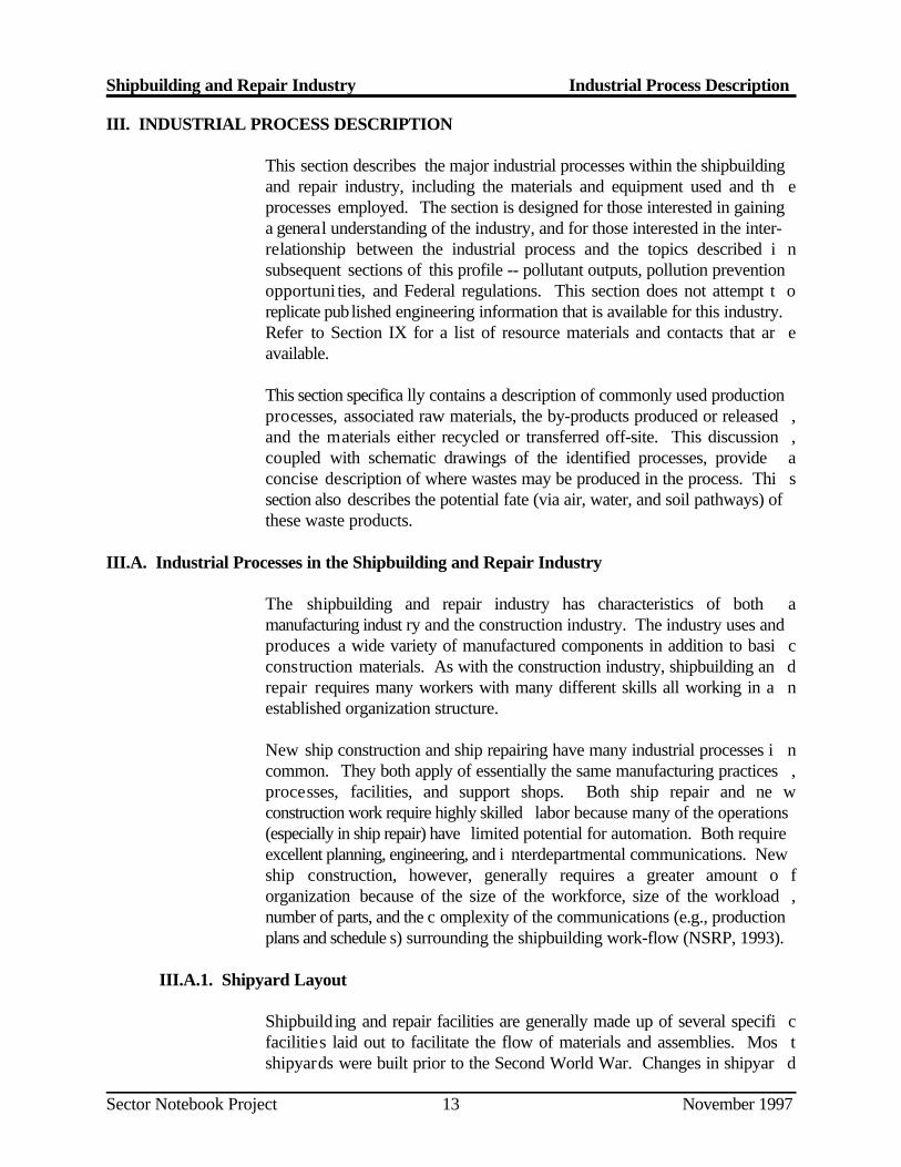
Shipbuilding and Repair Industry Industrial Process Description
Sector Notebook Project November 199713
III. INDUSTRIAL PROCESS DESCRIPTION
This section describes the major industrial processes within the shipbuildingand repair industry, including the materials and equipment used and th eprocesses employed. The section is designed for those interested in gaininga general understanding of the industry, and for those interested in the inter-relationship between the industrial process and the topics described i nsubsequent sections of this profile -- pollutant outputs, pollution preventionopportuni ties, and Federal regulations. This section does not attempt t oreplicate pub lished engineering information that is available for this industry.Refer to Section IX for a list of resource materials and contacts that ar eavailable.
This section specifica lly contains a description of commonly used productionprocesses, associated raw materials, the by-products produced or released ,and the materials either recycled or transferred off-site. This discussion ,coupled with schematic drawings of the identified processes, provide aconcise description of where wastes may be produced in the process. Thi ssection also describes the potential fate (via air, water, and soil pathways) ofthese waste products.
III.A. Industrial Processes in the Shipbuilding and Repair Industry
The shipbuilding and repair industry has characteristics of both amanufacturing indust ry and the construction industry. The industry uses andproduces a wide variety of manufactured components in addition to basi cconstruction materials. As with the construction industry, shipbuilding an drepair requires many workers with many different skills all working in a nestablished organization structure.
New ship construction and ship repairing have many industrial processes i ncommon. They both apply of essentially the same manufacturing practices ,processes, facilities, and support shops. Both ship repair and ne wconstruction work require highly skilled labor because many of the operations(especially in ship repair) have limited potential for automation. Both requireexcellent planning, engineering, and i nterdepartmental communications. Newship construction, however, generally requires a greater amount o forganization because of the size of the workforce, size of the workload ,number of parts, and the c omplexity of the communications (e.g., productionplans and schedule s) surrounding the shipbuilding work-flow (NSRP, 1993).
III.A.1. Shipyard Layout
Shipbuild ing and repair facilities are generally made up of several specifi cfacilities laid out to facilitate the flow of materials and assemblies. Mos tshipyards were built prior to the Second World War. Changes in shipyar d
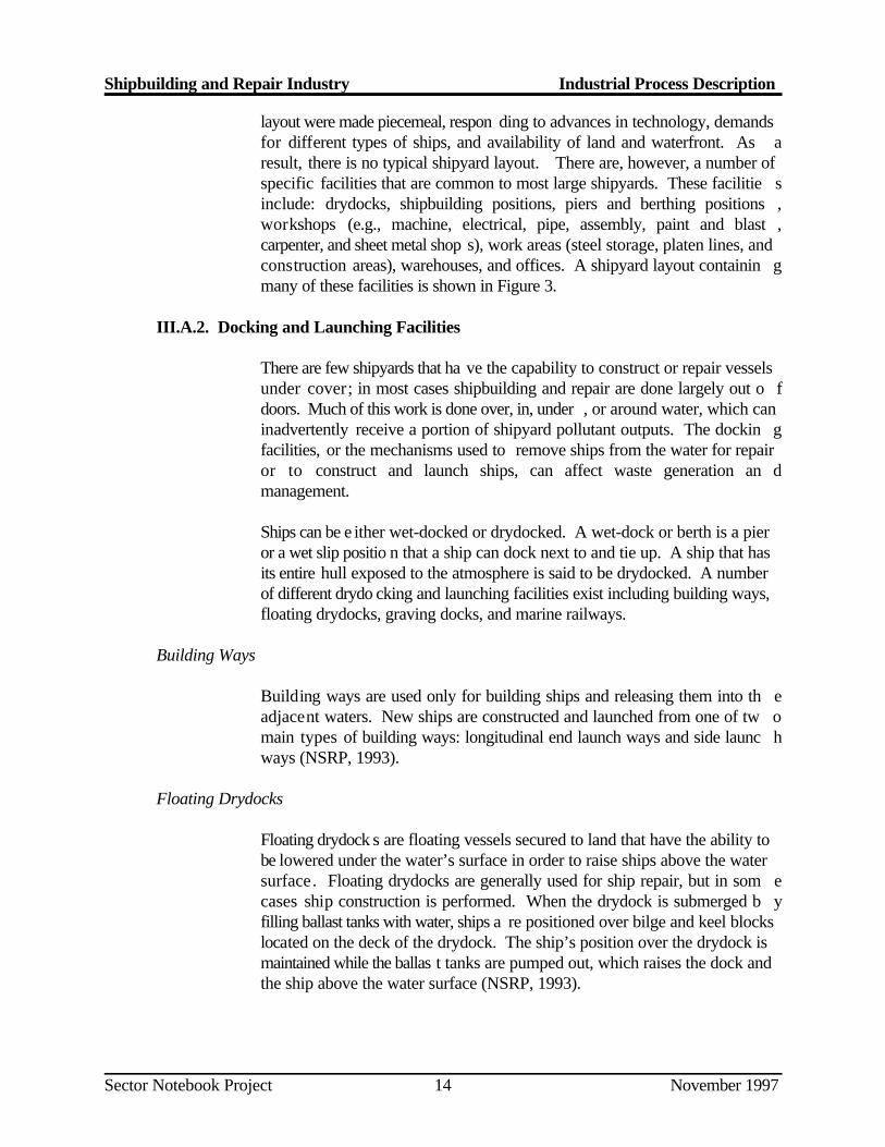
Shipbuilding and Repair Industry Industrial Process Description
Sector Notebook Project November 199714
layout were made piecemeal, respon ding to advances in technology, demandsfor different types of ships, and availability of land and waterfront. As aresult, there is no typical shipyard layout. There are, however, a number ofspecific facilities that are common to most large shipyards. These facilitie sinclude: drydocks, shipbuilding positions, piers and berthing positions ,workshops (e.g., machine, electrical, pipe, assembly, paint and blast ,carpenter, and sheet metal shop s), work areas (steel storage, platen lines, andconstruction areas), warehouses, and offices. A shipyard layout containin gmany of these facilities is shown in Figure 3.
III.A.2. Docking and Launching Facilities
There are few shipyards that ha ve the capability to construct or repair vesselsunder cover; in most cases shipbuilding and repair are done largely out o fdoors. Much of this work is done over, in, under , or around water, which caninadvertently receive a portion of shipyard pollutant outputs. The dockin gfacilities, or the mechanisms used to remove ships from the water for repairor to construct and launch ships, can affect waste generation an dmanagement.
Ships can be e ither wet-docked or drydocked. A wet-dock or berth is a pieror a wet slip positio n that a ship can dock next to and tie up. A ship that hasits entire hull exposed to the atmosphere is said to be drydocked. A numberof different drydo cking and launching facilities exist including building ways,floating drydocks, graving docks, and marine railways.
Building Ways
Building ways are used only for building ships and releasing them into th eadjacent waters. New ships are constructed and launched from one of tw omain types of building ways: longitudinal end launch ways and side launc hways (NSRP, 1993).
Floating Drydocks
Floating drydock s are floating vessels secured to land that have the ability tobe lowered under the water’s surface in order to raise ships above the watersurface. Floating drydocks are generally used for ship repair, but in som ecases ship construction is performed. When the drydock is submerged b yfilling ballast tanks with water, ships a re positioned over bilge and keel blockslocated on the deck of the drydock. The ship’s position over the drydock ismaintained while the ballas t tanks are pumped out, which raises the dock andthe ship above the water surface (NSRP, 1993).
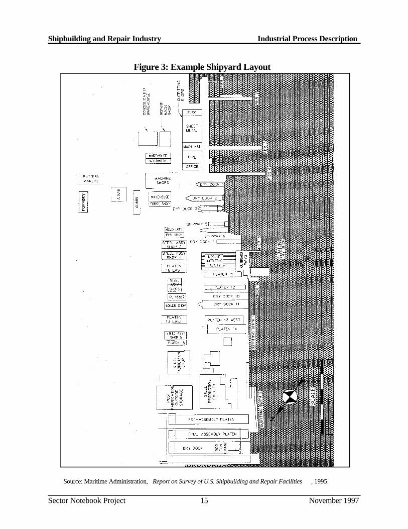
Shipbuilding and Repair Industry Industrial Process Description
Sector Notebook Project November 199715
Source: Maritime Administration, Report on Survey of U.S. Shipbuilding and Repair Facilities , 1995.
Figure 3: Example Shipyard Layout
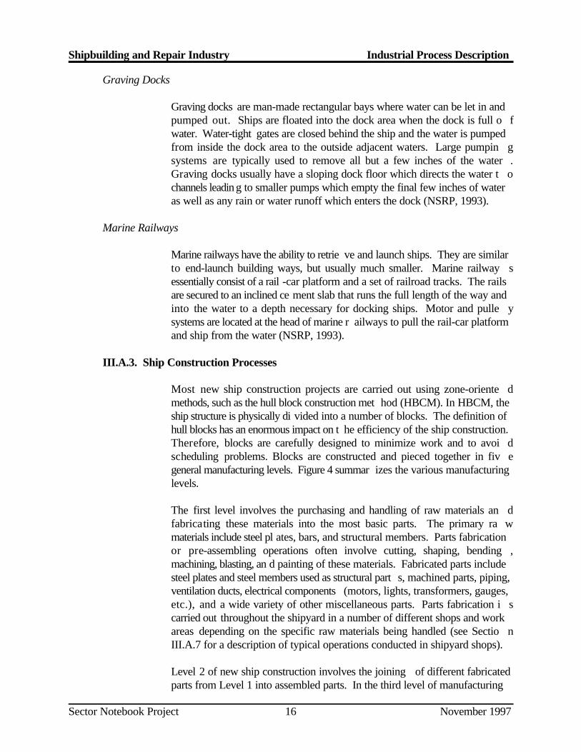
Shipbuilding and Repair Industry Industrial Process Description
Sector Notebook Project November 199716
Graving Docks
Graving docks are man-made rectangular bays where water can be let in andpumped out. Ships are floated into the dock area when the dock is full o fwater. Water-tight gates are closed behind the ship and the water is pumpedfrom inside the dock area to the outside adjacent waters. Large pumpin gsystems are typically used to remove all but a few inches of the water .Graving docks usually have a sloping dock floor which directs the water t ochannels leadin g to smaller pumps which empty the final few inches of wateras well as any rain or water runoff which enters the dock (NSRP, 1993).
Marine Railways
Marine railways have the ability to retrie ve and launch ships. They are similarto end-launch building ways, but usually much smaller. Marine railway sessentially consist of a rail -car platform and a set of railroad tracks. The railsare secured to an inclined ce ment slab that runs the full length of the way andinto the water to a depth necessary for docking ships. Motor and pulle ysystems are located at the head of marine r ailways to pull the rail-car platformand ship from the water (NSRP, 1993).
III.A.3. Ship Construction Processes
Most new ship construction projects are carried out using zone-oriente dmethods, such as the hull block construction met hod (HBCM). In HBCM, theship structure is physically di vided into a number of blocks. The definition ofhull blocks has an enormous impact on t he efficiency of the ship construction.Therefore, blocks are carefully designed to minimize work and to avoi dscheduling problems. Blocks are constructed and pieced together in fiv egeneral manufacturing levels. Figure 4 summar izes the various manufacturinglevels.
The first level involves the purchasing and handling of raw materials an dfabricating these materials into the most basic parts. The primary ra wmaterials include steel pl ates, bars, and structural members. Parts fabricationor pre-assembling operations often involve cutting, shaping, bending ,machining, blasting, an d painting of these materials. Fabricated parts includesteel plates and steel members used as structural part s, machined parts, piping,ventilation ducts, electrical components (motors, lights, transformers, gauges,etc.), and a wide variety of other miscellaneous parts. Parts fabrication i scarried out throughout the shipyard in a number of different shops and workareas depending on the specific raw materials being handled (see Sectio nIII.A.7 for a description of typical operations conducted in shipyard shops).
Level 2 of new ship construction involves the joining of different fabricatedparts from Level 1 into assembled parts. In the third level of manufacturing
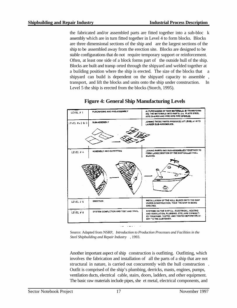
Shipbuilding and Repair Industry Industrial Process Description
Sector Notebook Project November 199717
Figure 4: General Ship Manufacturing Levels
Source: Adapted from NSRP, Introduction to Production Processes and Facilities in theSteel Shipbuilding and Repair Industry , 1993.
the fabricated and/or assembled parts are fitted together into a sub-bloc kassembly which are in turn fitted together in Level 4 to form blocks. Blocksare three dimensional sections of the ship and are the largest sections of theship to be assembled away from the erection site. Blocks are designed to bestable configurations that do not require temporary support or reinforcement.Often, at least one side of a block forms part of the outside hull of the ship.Blocks are built and transp orted through the shipyard and welded together ata building position where the ship is erected. The size of the blocks that ashipyard can build is dependent on the shipyard capacity to assemble ,transport, and lift the blocks and units onto the ship under construction. InLevel 5 the ship is erected from the blocks (Storch, 1995).
Another important aspect of ship construction is outfitting. Outfitting, whichinvolves the fabrication and installation of all the parts of a ship that are notstructural in nature, is carried out concurrently with the hull construction .Outfit is comprised of the ship’s plumbing, derricks, masts, engines, pumps,ventilation ducts, electrical cable, stairs, doors, ladders, and other equipment.The basic raw materials include pipes, she et metal, electrical components, and
Shipbuilding and Repair Industry Industrial Process Description
Sector Notebook Project November 199718
machinery. A zone-oriented method is typically used to assemble the partsthat form major machinery spaces onboard the ship including engine rooms,pump rooms, and auxiliary machinery spaces. Parts or fittings can b eassembled onboa rd the ship during hull erection, on the blocks or subblocks,or independent of the hull structure in units of similar parts (NSRP, 1993).
III.A.4. Major Production Facilities
Most shipbuilding yard s have in common the following major facilities, workareas, or specialized equipment.
Prime Line
The prime line is a large machine that blasts and primes (paints) raw stee lsheets, preparing them for production. Steel sheets, parts, and shapes enterone end of the prime line, go through a blasting section, then through apriming section. The primer is re ferred to as construction primer, and is usedto prevent corrosion during the production pro cess. Section III.A.9 discussessurface preparation and coating operations in more detail (NSRP, 1993).
Panel Lines
Panel lines typically consist of motor driven conveyors and rollers used t omove large steel plates together for joining . The use of panel lines introducedmanufacturing production l ine techniques into the steel shipbuilding industry.Joining of plates involves the welding of the seams either on one side or twosides. Two sided w elding requires the panel line to be capable of turning thesteel plates over after one-side is welded. Vertical stiffeners are also weldedon the panel line often using automated welding machines. After welding ,excess steel is cut off using gas cutting equipment. Panel assemblies ar etypically moved through the line with the aid of magnetic cranes (NSRP ,1993).
Platen Lines
The platen lines (or platens) are the area in the shipyard where blocks ar eassembled. Therefore, platens form assembly lines where the steel structuresof construction blocks are fabric ated. Sub-assemblies from the panel line andplate shop are brought toget her at the platen and assembled into blocks. Theplaten mainly provides locat ions for sub-assembly construction, block layout,tack-welding, and final weld out. The platen lines a re serviced by welding andsteel cutting equipment and cranes for materials movement (NSRP, 1993).
Shipbuilding and Repair Industry Industrial Process Description
Sector Notebook Project November 199719
Rolls
Rolls are large facilities that bend and shape steel plates into curved surfaceplates for the curved portion of the hull. Rolls consi st of large cylindrical steelshafts and a motor drive. Rolls vary greatly in size and technology fro mshipyard to shipyard. Some of the n ewer rolls are computer controlled, whilethe older machines are manually operated (NSRP, 1993).
Pin Jigs
Pin jigs are platen lines used to assemble the curved blocks that form th eoutside of the hull’s curved surface. The pin jig is simply a series of verticalscrew jacks that support curved blocks during construction. A pin jig is setup specifically for the curved block under construction. The jig heights ar edetermined from the ship’s engineering drawings and plans (NSRP, 1993).
Rotary Tables
Rotary tables are facilities that hull block s are set into and which mechanicallyrotate the block. The ability to easily rotate an entire block in a single locationreduces the number of time-consuming crane lifts that would otherwise b eneeded. Rotary tables also exploit the increased effici encies experienced whenworkers are able to weld on a verti cal line (down hand). Down hand weldingprovides a higher quality weld with higher efficiency rates. Turn tables ar ealso used for outfitting materials on the block because of easier access t ooutfitting locations (NSRP, 1993).
Materials Handling
Materials handling is an important aspect of efficient shipbuilding .Considerable coordination is needed between materials delivery and th eproduction schedule. Materials need to be delivered to the proper location inthe shipyard at the proper time to be installed on the construction block .Typical materials handling equipment includes conveyors, cranes, industria lvehicles (e.g., forklifts, flatbeds, carts, special lift vehicles, etc.), an dcontainers (NSRP, 1993).
III.A.5. Welding
The structural framework of most ships is constructed of various grades o fmild and high strength steel. Aluminum and other nonferrous materials areused for some superstructures (deck-houses) and other areas requirin gspecific corrosion resistance and structural requirements. However, othe rcommon materials such as stainless steel, galvanized steel, and copper nickelalloys, are used in far less quantities than steel (ILO, 1996).
Shipbuilding and Repair Industry Industrial Process Description
Sector Notebook Project November 199720
The primary raw materia l for ship construction is steel plate. Steel plates aretypically cut to the desired size by automatic burners before being welde dtogether to form the structural components of the vessel.
Shipyard welding processes are performed at nearly every location in th eshipyard. The process involves joining metals by bringing the adjoinin gsurfaces to extremely high temperatures to be fused together with a molte nfiller material. An electric arc or gas flame are used to heat the edges of thejoint, permitting them to fuse with molten weld fill metal in the form of a nelectrode, wire, or rod. Ther e are many different welding techniques used bythe industry . Most welding techniques can be classified as either electric arcor gas welding, with electric arc being the most common (ILO, 1996).
An important factor impacting the strength of welds is arc shielding, isolatingthe molten metal weld pool from the atmosphere. At the extremely hig htemperatures used in welding, the molten metal reacts rap idly with oxygen andnitrogen in the atmosphere which decreases the weld strength. To protec tagainst this weld impurity and ensure weld quality, shielding from th eatmosphere is required. In most welding processes, shielding is accomplishedby addition of a flux, a gas, or a combination of the two. Where a flu xmaterial is used, gases generated by vaporization and chemical reaction at theelectrode tip result in a combination of flux and gas shielding that protect theweld from the atmosphere. The various types of electri c arc welding (shieldedmetal arc, submerge d arc, gas metal arc, gas tungsten arc, flux core arc, andplasma-arc) all use different methods to accomplis h arc shielding (ILO, 1996).
III.A.6. Ship Repairing Processes
Ship repair generally includes all ship conversions, overhauls, maintenanc eprograms, major damage repairs, and minor equipment repairs. Althoug hspecific repair methods vary from job to job, many of the operations ar eidentical to new ship construction operations. Repair operations, however ,are typically on a smaller scale and are performed at a faster pace. Jobs canlast anywhere from one day to over a year. Repair jobs o ften have severe timeconstraints requ iring work to be completed as quickly as possible in order toget the ships back in service. In many cases, piping, ventilation, electrical, andother machinery are prefabricated prior to the ship’s arri val. Often, repair jobsare an emergency situation with very little warning, which makes ship repaira fast moving and unpredictable environment. Ty pical maintenance and repairoperations include:
Blasting and repainting the ship’s hull, freeboard, superstructure, andinterior tanks and work areas
Major rebuilding and installation of machinery such as diesel engines,turbines, generators, pump stations, etc.
Shipbuilding and Repair Industry Industrial Process Description
Sector Notebook Project November 199721
Systems overhauls, maintenance, and installation (e.g., piping systemflushing, testing, and installation)
System replacement and new installation of systems such a snavigational systems, combat systems, communication systems ,updated piping systems, etc.
Propeller and rudder repairs, modification, and alignment
Creation of new machinery spaces through cut outs of the existin gsteel structure and the addition of new walls, stiffeners, vertical ,webbing, etc.
In addition, some larger shipyards are capable of large repair and conversionprojects that c ould include: converting supply ships to hospital ships, cuttinga ship in half and installing a new section to lengthen the ship, replacin gsegments of a ship that has run aground, completing rip-out, structura lreconfiguration and ou tfitting of combat systems, major remodeling of ships’interiors or exteriors (NSRP, 1993).
III.A.7. Support Shops and Services
Shipyards typically have a number of support shops that either proces sspecific raw materials (e.g., pipes, electric, sheet metal, machinery, plates ,paint, etc.) or provide specialty services (e.g., carpentry, maintenance ,materials trans porting, warehousing, etc.). In many ways, support shops aresmall manufacturers producing goods to support the production effor t(NSRP, 1993). Common shipbuilding and repair yard support shops an dservices are described below.
Pipe Shop
The pipe shop is responsible for manufacturing and assembl ing piping systems.Piping systems are the largest outfitting task in shipbuilding. Small pip esections known as “pipe spools” are assembled in the pipe shop an dtransported to the stages of construction (i.e., assembly, on-block, on-unit ,and on-board). Pipe spools are shaped and manufactured per engineerin gdesign, are scheduled for construction, and sent to the various stages fo rinstallation. Many pipe shops will tag the spools to identify the location forinstallation on the block and ship. A typical ship may have anywhere fro m10,000 to 25,000 pipe spools. Some of the processes in the pipe sho pinclude: pipe welding, pipe bending, flux removal, grit-blast, pickling ,painting, galvanizing, and pressure testing. Some of the equipment used bythe pipe shop are as follows: pipe welders, lathes, pipe cutting saws, shears,grinders, chippers, hole cutters, pipe benders, pickling tanks, an dtransportation equipment (NSRP, 1993).
Shipbuilding and Repair Industry Industrial Process Description
Sector Notebook Project November 199722
Machine Shop
The machine shop serves the entire shipyard’s machining needs though th eexact functions of the shipyard machine shops vary throughout th eshipbuilding industry. Shipyard machine shops perform functions rangin gfrom rebuilding pumps to turning 25 foot long prope ller drive shafts on lathes.Equipment in the machine shop consists of: end mills, lathes, drill presses ,milling machines, band saws, large presses, work tables, and cleaning tank s(NSRP, 1993).
Sheet Metal Shop
The sheet metal shop is generally responsible for fabricating and installin gventilation ducting and vent spools. Using engineering drawings and specialsheet metal tools this shop produces ventilat ion systems for new construction,as well as repair work. The shop cuts, shapes, bends, welds, stamps, paints,and performs a variety of manufacturing operations for ship ventilatio nsystems. Many sheet metal shops are also responsible for assembling larg educting fans and heating and air conditioning components. Sheet meta lworkers perform the installation of the ducting in various stages o fconstruction such as on-block, on-unit, onboard (NSRP, 1993).
Electrical Shop
Electrical shops in the shipy ard perform a variety of functions throughout theindustry. In many cases, the elec trical shop installs, rebuilds, builds, and testselectrical components (e.g., motors, lights, transformers, gauges, etc.). Theelectrical shop electricians also install the electrical equipment on the shi peither on-block or onboard. On-block is where the electrical parts ar einstalled and onboard is where cables are routed throughout the shi pconnecting the electrical systems together. Electric shops generally hav eplating tanks, dip tanks for lac quer coatings, electrical testing equipment, andother specialized equipment (NSRP, 1993).
Foundry/Blacksmith Shop
The blacksmith shop is an older term used for t he shipyard shop that performsforging or castings. Forging and casting at shipyards are somewhat rare .Over the years, forging and casting functions have been shifted t osubcontractors off-site. The subcontractors are usually foundries whos eprimary function is forging and casting. Shi pyards that have blacksmith shopsmaintain large furnaces and other foundry equipment (NSRP, 1993).
Shipbuilding and Repair Industry Industrial Process Description
Sector Notebook Project November 199723
Plate Shop
The plate shop is a generic term used for the area and process in the shipyardthat provides steel parts cutting, bending, and sub-assembly. The plate shopuses information from engineering drawings to produce plate shapes. Th eshapes are cut and formed as needed. Most plate shops have manual an dcomputer controlled machinery. The types of machinery commonly found inthe plate shop are cutting machines, st eel bending machines and plate bendingrolls, shearing machines, presses, hole punching equipment, and furnaces forheat treatment. The plate shop sends the parts and sub-assemblies that theymanufacture to the stages of construction, or the platen area for installation(NSRP, 1993).
Production Services
Services provided by this departm ent include: carpentry, scaffolding erection,crane operations, rigging, facility and equipment maintenance, and othe rproduction support activities. The production services may be grouped intoone department or divided into unique shops for each service provide d(NSRP, 1993).
III.A.8. Solvent Cleaning and Degreasing
Solvent cleaning and degreasing are common in the shipbuilding and repai rindustry (although many facilities are replacing solvent cleaning an ddegreasing with aqueous and alkaline cleaning and degreasing). Solven tcleaning and degreasin g are typically accomplished by either cold cleaning orvapor degreasing. Cold cleaning refers to operations in which the solvent isused at room temperature. The surfaces or parts are soaked in a tank o fsolvent, or sprayed, brushed, wiped, or flushed with solvent. Diphas ecleaning is sometimes used to combine a water rinse before and after th esolvent cleaning into a single step. In diphase cleaning, water insolubl ehalogenated solvents and water are placed in a single t ank where they separatewith the solvent on the bottom. Parts are lowered through the water bat hbefore reaching the solvent and then are rinsed through the water level as theyare removed from the tank.
In vapor degreasing, parts and surfaces are cleaned with a hot solvent vapor.Solvent in a specially designed tank is boiled creating a solvent vapor in theupper portion of the tank. The parts are held in the vapor zone where solventvapor condenses on the sur face removing dirt and oil as it drips back into theliquid solvent. In this way, only clean solvent vap ors come in contact with thepart. A condensing coils at the top of the tank reduces the amounts o fsolvents escaping to the atmosphere (NSRP, 1993).
Shipbuilding and Repair Industry Industrial Process Description
Sector Notebook Project November 199724
III.A.9. Surface Preparation
To a large extent, the effectivene ss of the surface coating relies on the qualityof surface preparation. All paints will fail eventually, but the majority o fpremature failures are due to loss of adhesion caused by improper surfac epreparation. Surface preparation is also typically one of the most significantsources of shipyard wastes and pollutant outputs. Section III.B.1 discusseswaste generation and pollution outputs from these operations.
Surface preparation techniques are used to remove surface contaminants suchas mill scale, rust, dirt, dust, salts, old paint, grease, and flux. Contaminantsthat remain on the surface are the primary causes of premature failure o fcoating systems. Depending on the surface location, contaminants, an dmaterials, a number of different surface preparation techniques are used in theshipbuilding and repair industry:
Solvent, Detergent, and Steam CleaningBlasting Hand Tool PreparationWet Abrasive Blasting and Hydroblasting Chemical Preparation
Solvent, Detergent, and Steam Cleaning
The process of removing grease, oil and other contaminants with the aid o fsolvents, emulsions, detergents, and other cleaning compounds is frequentlyused for surface preparation in the shipbuilding industry. Solvent cleanin ginvolves wiping, scrubbing, immersio n in solvent, spraying, vapor degreasing,and emulsion cleaning the surface with rags or brushes until the surface i scleaned. The final wipe down must be performed with a clean rag or brush,and solvent. Inorganic compound s such as chlorides, sulfates, weld flux, rustand mill scale cannot be removed with organic solvents.
In many cases steam cleaning is a better alternative to solvent wipe down .Steam cleaning or high pressure washing is used to r emove dirt and grime thatis present on top of existing paint and bare steel. Many hot steam cleaner swith detergents will remove most petroleum products and sometimes, ol dchipping paint. After steam cleaning the part should be rinsed with fres hwater and allowed to dry. Often the sur face is ready to prime, although manysurfaces will require further preparation before painting.
Blasting
Abrasive blasting is the most common method for paint removal and surfacepreparation. Copper slag, coal slag, steel grit, and steel shot are commo nblasting abrasives. Copper and steel grit consist of small angular particles ,
Shipbuilding and Repair Industry Industrial Process Description
Sector Notebook Project November 199725
while steel shot is made up of small round balls. Copper slag can generally beused only once or twice before it becomes too small to be effective. Steel gritand shot can typically be used between 50 and 5,000 times before becomingineffective. Met allic grit and shot are available in varying ranges of hardnessand size.
Centrifugal blasting machin es, also called roto-blasting or automatic blasting,are one of the more popular methods of blasting steel surfaces. In centrifugalblasting, metallic shot or grit is propelled to the surface to be prepared by aspinning wheel. Centrif ugal blasting machines tend to be large and not easilymobilized. Therefore, they are not applicable to all shipyard blasting needs.Parts to be prepared must be brought to the machine and passed through ona conveyor or rotary table. On flat surfaces , centrifugal blasting machines canproduce uniform blasting results at high production rates. More time i srequired to prepare surfaces that are hard to reach. The process allows easyrecovery of abrasive materials for reuse and recycling which can result i nsignificant savi ngs in materials and disposal costs. Large centrifugal blastingmachines are often found in the prime line for preparing raw steel sheet sbefore priming. Other centrifugal blasting machines are smaller and can b eused to prepare small parts, pipe spools, and steel subassemblies prior t opainting.
Air nozzle blasting (or dry abrasive blasting) is one of the most common typesof blasting in the shipbuilding and repair industry. In air nozzle blasting ,abrasive is conveyed to the surface to be prepared in a medium of hig hpressure air ( approximately 100 pounds per square inch) through a nozzle atvelocities approaching 450 feet per second. Abrasives are copper slag, coalslag and other metallic grit. Typically copper slag is used on the west coastand coal slag is used on the east coast. Traditionally sand was used, bu tmetallic grit has replaced it due to the adverse health and environmenta leffects of silica dust associated with sand. Air nozzle blasting is generall ycarried out manually by shipyard workers either within a building or in th eopen air, depending on the application . If the application allows, blast boothscan be used for containing abrasives.
Hand Tool Preparation
Hand tools such as grinders, wire brus hes, sanders, chipping hammers, needleguns, rotary peening tools, and other impact tools are commonly used in theshipyard for surface preparation. The han d tools are ideal for small jobs, hardto reach areas, and areas where blast ing grit would be too difficult to contain.Cleaning surfac es with hand tools seems comparatively slow although, whenremoving heavy paint formulations and heavy rust, they are effective an deconomical. Impact tools like chipping and nee dle guns are best for removingheavy deposits of britt le substances (e.g., rust and old paint). Hand tools aregenerally less effective when removing tight surface mill scale or surfac e
Shipbuilding and Repair Industry Industrial Process Description
Sector Notebook Project November 199726
rusting, because they can damage the metal surface. Surface preparation handtools are generally pneumatic instea d of electric because they are lighter, easyto handle, do not overheat, and there is no risk of electric shock.
Wet Abrasive Blasting and Hydroblasting
Wet abrasive blasting and hydroblasting are generally performed on ship sbeing repaired in a floating drydo ck, graving dock, or other building or repairposition. Wet abras ive blasting involves blasting with a mixture of water, airand solid abrasives. Wet abrasive blasting does not occur throughout th eshipyard like dry abrasive blasting because of the problem of water blas tcontainment. In part due to lack of customer acceptance, wet abrasiv eblasting is not common in the shipbuilding and repair industry at this time .Instead, hydroblasting is a widely used wet bla sting technique which uses onlyhigh pressure water to remove chipping paint, marine growth, mud, and saltwater from the ship’s hull. A small amount of rust inhibitor may be used inthe water to prevent flash rusting. Hydro basting is often followed by ai rnozzle blasting for final surface preparation.
Chemical Preparation
Chemical surface preparations consist of paint removers, alkaline cleanin gsolutions, chlorinated solvents, and pickling. Alkaline cleaning solutions comein a variety of forms and are used in a variety of manners. Alkaline cleanerscan be brushed on, sprayed on, and applied in a dip tank. Alkaline dip tanksof caustic soda solution are frequently used for cleaning parts and preparingthem for painting . After the surface is cleaned, it is thoroughly rinsed beforea coating system is applied. Many solvents and alkaline cleaners cannot b eused for nonferrous materials, such as bro nze, aluminum, and galvanized steelwhich are frequently found on ships.
Pickling is a process of chemical abr asion/etching which prepares surfaces forgood paint adhesion. The pickling process is used in shipyards mainly fo rpreparing pipe systems and small parts for paint. However, the process andqualities will vary from shipyard to shipyard. The process involves a systemof dip tanks. Figure 5 displays how the tanks can be arranged. In picklin gsteel parts and piping systems, Tank #1 is used to remo ve any oil, grease, flux,and other contamina nts on the surface being pickled. The content in tank #1are generally a 5-8% caustic soda and water mixture maintained a ttemperatures of between 180 -200 F. The part is then immersed into tank#2, which is the caustic soda rinse tank (pH 8-13). Next, the steel is dippedinto tank #3B, which is a 6-10% sulfuric acid/water mixture maintaine dbetween 140 -160 F. Tank #4 is the acid rinse tank that is maintained at apH of 5-7. Finally the steel pipe or part is immersed in a rust preventative 5%phosphoric mixture in t ank #5. The part is allowed to fully dry prior to paintapplication.
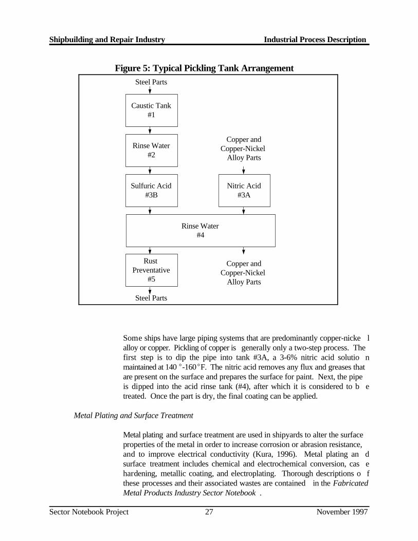
Steel Parts
Caustic Tank#1
Rinse Water#2
Sulfuric Acid#3B
Rinse Water#4
Rust Preventative
#5
Steel Parts
Copper andCopper-Nickel
Alloy Parts
Nitric Acid#3A
Copper andCopper-Nickel
Alloy Parts
Shipbuilding and Repair Industry Industrial Process Description
Sector Notebook Project November 199727
Figure 5: Typical Pickling Tank Arrangement
Some ships have large piping systems that are predominantly copper-nicke lalloy or copper. Pickling of copper is generally only a two-step process. Thefirst step is to dip the pipe into tank #3A, a 3-6% nitric acid solutio nmaintained at 140 -160 F. The nitric acid removes any flux and greases thatare present on the surface and prepares the surface for paint. Next, the pipeis dipped into the acid rinse tank (#4), after which it is considered to b etreated. Once the part is dry, the final coating can be applied.
Metal Plating and Surface Treatment
Metal plating and surface treatment are used in shipyards to alter the surfaceproperties of the metal in order to increase corrosion or abrasion resistance,and to improve electrical conductivity (Kura, 1996). Metal plating an dsurface treatment includes chemical and electrochemical conversion, cas ehardening, metallic coating, and electroplating. Thorough descriptions o fthese processes and their associated wastes are contained in the FabricatedMetal Products Industry Sector Notebook .
Shipbuilding and Repair Industry Industrial Process Description
Sector Notebook Project November 199728
III.A.10. Painting Processes
Proper surface coating system application is essential in the shipbuilding andrepair industry. The corrosion and deterioration associated with the marineenvironment has detrimental effects on ships and shipboard components .Maintaining ships’ structural integrity and the proper functioning of thei rcomponents are the main purposes of shipboard coating systems.
Painting is performed at almost every location within shipyards. This is dueto the wide variety of work performed throughout shipyards. The nature ofshipbuilding and repair requires several types of paints to be used for avariety of applications. Paint types range from water-based coatings to highperformance epoxy coatings. The type of paint needed for a certai napplication depends on the environment that the coating will be exposed. Ingeneral there are six areas where shipboard paint requirements exist:
Underwater (Hull Bottom)WaterlineTopside SuperstructuresInternal Spaces and TanksWeather DecksLoose Equipment
Because paint sys tems are often specified by the customer or are supplied bythe ship owner, shipyards often may not be able to choose or recommend aparticular system. Navy ships may require a specific type of paint for everyapplication through a military specification (Mil-spec). Many factors ar econsidered when choosing a particular application. Among the factors ar eenvironmental conditions, severity of environmental exposure, drying an dcuring times, application equipment and procedures, etc.
Paint Coating Systems
Paints are made up of three main ingredients: pigment, binder, and a solventvehicle. Pigments are small particles that generally de termine the color as wellas many other pro perties associated with the coating. Examples of pigmentsinclude: zinc oxide, talc, carbon, coal tar, lead, mica, aluminum, and zinc dust.The binder can be thought of as the glue that holds the paint pigment stogether. Many paints are referred to by their binder type (e.g., epoxy, alkyd,urethane, vinyl, phenolic, etc.). The binder is also very important fo rdetermining a coating’s performa nce characteristics (e.g., flexibility, chemicalresistance, durability, finish, etc.). The solvent is added to thin the paints sothat it will f low to the surface and then dry. The solvent portion of the paintevaporates when the paint dries. Some typical solvents include acetone ,mineral spirits, xylene, methyl ethyl ketone, and water.
Shipbuilding and Repair Industry Industrial Process Description
Sector Notebook Project November 199729
Anticorrosive and ant ifouling paints are typically used on ship’s hulls and arethe main two types of paint used in the shipbuilding industry. Antifoulin gpaints are used to prevent the growth of marine organisms on the hull o fvessels. Copper-based and tributyl-tin-based paints are widely used a santifouling paints. These paints release small quantities of toxics whic hdiscourage marine life from growing on the hull. Anticorrosive paints ar eeither vinyl, lacquer, urethane, or newer epoxy-based coating systems (ILO,1996).
The first coating system applied to raw steel sheets and parts is generally pre-construction primer. This pre-construction primer is sometimes referred t oas shop primer. This coat of primer is importa nt for maintaining the conditionof the part throug hout the construction process. Pre-construction priming isperformed on steel plate s, shapes, sections of piping, and ventilation ducting.Most pre-construction primers are zinc-rich with organic or inorganic binders.Zinc silicates are predominant among the inorganic zinc primers. Zinc coatingsystems protect coatings in much the same manner as galvanizing. If zinc iscoated on steel, oxygen will react with the zinc to form zinc oxide, whic hforms a tight layer tha t does not allow water or air to come into contact withthe steel (ILO, 1996).
Paint Application Equipment
There are many types of paint application equipment used in the shipbuildingindustry. Two main methods used are compressed air and airless sprayers .Compressed air sprayers are being phased out in the industry because of thelow transfer ability of the system. Air assisted paint systems spray both ai rand paint, which causes some paint to atomize and dry quickly prior t oreaching the intended surface. The transfer efficiency of air assisted spra ysystems can vary from 65% to 80%. This low transfer eff iciency is due mainlyto overspray, drift, and the air sprayer’s inefficiencies (ILO, 1996).
The most widely used form of paint application in the shipbuilding industry isthe airless sprayer. The airless sprayer is a system that simply compresse spaint in a hydraulic line and has a spray nozzle at the end. Airless sprayers usehydrostatic pressure instead of air to convey the paint. They are much cleanerto operate and have fewer leaking problems because the system requires lesspressure. Airless sprayers can have up to 90% transfer efficiency. A ne wtechnology that can be added to the airless sprayer is called High Volum eLow Pressure (HVLP). HVLP offers an even higher transfer efficiency, i ncertain conditions (ILO, 1996).
Thermal spray is the application of aluminum or zinc coatings to steel for longterm corrosion protection. Thermal spray can also be referred to as meta lspray or flame spray. Thermal spray is significantly different tha nconventional coating prac tices due to its specialized equipment and relatively
Shipbuilding and Repair Industry Industrial Process Description
Sector Notebook Project November 199730
slow production rates. The initial cost of thermal spray is usually hig hcompared to painting, although when the life-cycle is taken into account ,thermal spray becomes more economically attractive. Many shipyards havetheir own thermal spray machines and other shipyards will subcontract theirthermal coating work. Thermal spray can occur in a shop o r onboard the ship.There are two basic types of thermal coating machines: combustion wire andarc spray. The combustion wire type consists of combus tible gasses and flamesystem with a wire feed controller. The combustible gasses melt the materialto be sprayed onto the parts. The electric arc spray machine instead uses apower supply arc to melt the flame sprayed material (ILO, 1996).
Painting Practices and Methods
Painting is performed in nearly every area in the shipyard from the initia lpriming of the steel to the final paint detailing of the ship. Methods fo rpainting vary greatly from process to process. Mixing of paint is performedboth manually and mechanically and should be done in an area contained byberms, tarps, secondary containment pallets. Outdoor as well as indoo rpainting occurs in the shipyard. Shrouding fences, made of steel, plastic, orfabric, are frequently used to help contain paint overspray by blocking th ewind and catching paint particles (NSRP, 1996).
Hull painting occurs on both repair ships and new construction ships. Hul lsurface preparation and painting on repair ships is normally performed whenthe ship is fully drydocked (i.e., graving-dock or floating drydock). For newconstruction, the hull is prepared and painted at a building position using oneof the techniques discussed in the previous sections. Paint systems ar esprayed onto the hull using airless sprayers and high reach equipment such asman-lifts, scissor lifts, or portable scaffolding (ILO, 1996).
The superstructure of the ship consists of the exposed decks, deck houses ,and structures above the main deck. In many cases, scaffolding is use donboard the ship to reach antennas, houses, and other superstructures .Shrouding is usually put into place if it is l ikely that paint or blast material willfall into adjacent waters. On repair ships, the ship’s superstructure is paintedmostly while berthed. The painters access the superstructures with existin gscaffolding, ladders, and various lifting equipment that was used durin gsurface preparation. The shrouding system (if applicable) that was used forblast containment will st ay in place to help contain any paint overspray (ILO,1996).
Tanks and compartments onboard ships must be coated and re-coated t omaintain the lon gevity of the ship. Re-coating of repair ship tanks requires alarge amount of surface preparation prior to painting. The majority of th etanks are at the bottom of the ship (e.g., ballast tanks, bilges, fuel, etc.). Thetanks are prepared for paint by using solvents and detergents to remov e
Shipbuilding and Repair Industry Industrial Process Description
Sector Notebook Project November 199731
grease and oil build-up. The associated waste-water developed during tankcleaning must be prope rly treated and disposed of. After the tanks are dried,they are blasted with a mineral slag. Once the surface is blasted and the gritis removed, painting can begin. Adequate ventilation and respirators are astrict requirement for all tank and compartment surface preparation an dpainting (ILO, 1996).
Painting is also carried out after the assembly of hull blocks. Once the blocksleave the assembly area, they are frequently transported to a blast area wherethe entire block is prepared for paint. At this point, the block is usuall yblasted back down to bare metal (i.e., the construction primer is removed) .However, many shipyards are now moving towards implementing apreconstruction primer that does no t need to be removed. The most frequentmethod for block surface pr eparation is air nozzle blasting. The paint systemis applied by painters generally using airless spray equipment on acces splatforms. Once the block’s coating system has been applied, the block i stransported to the on-block stage where outfitting materia ls are installed (ILO,1996).
Many parts need to have a coating system applied prior to installation. Forexample, piping spools, vent ducting, foundations, and doors are painte dbefore they are installed on-block. Some small parts painting occurs in th evarious shops whi le others are painted in a standard location operated by thepaint department (ILO, 1996). Indoor painting of this type usually occurs ina spray booth. Spray booths capture overspray, control the introduction ofcontaminants to the workplace environment, and reduce the likelihood o fexplosions and fires. Paint booths are categorized by the method used fo rcollecting the overspray (EPA, 1995).
The two primary types of paint booths are dry filter and water wash booths.Dry filter booths u se filter media (usually paper or cloth filters) to screen outthe paint solids by pulling prefiltered air through the booth, past the sprayingoperation, and through the filter media. Water wash booths use a “wate rcurtain” to capture paint overspray by pulling air containing entrained paintoverspray through a circulated water stream which “scrubs” the overspra yfrom the air. Water is periodically added to the paint booth reservoir t ocompensate for evaporative losses, and chemicals are periodically added t oimprove paint sludge formation. T he sump is periodically discharged, usuallyduring general system cleaning or maintenance (EPA, 1995).
III.A.11. Fiberglass Reinforced Construction Operations
Many of the medium and small shipyards manufacture and repair fiberglas sships and boats or construct fiberglass parts for steel ships. The proces sinvolves combining polymerizing resin with fiberglass reinforcing material. The resin is polymerized with a catalyst or curing a gent. Once cured, the hard
Shipbuilding and Repair Industry Industrial Process Description
Sector Notebook Project November 199732
resin cannot be softened or reshaped and is stronger than composite plasticswithout the reinforcing. Fiberglass material con sists of a woven mat of glass-like fibers. The fiberglass content of the reinforced product ranges from 25 to60 percent.
A number of different processes are used, but the mold-based process is themost common for this industry. Mold-based fibe rglass reinforced constructiontypically involves either the hand app lication or spray application of fiberglassreinforcing. In the hand application method, the reinforcing material i smanually applied to a mold wetted with catalyzed resin mix or gelcoat an dthen sprayed or brushed with more resin or gelcoat. In the sprayup method,catalyzed resin and fiberglass reinforcement are mechanically sprayed onto themold surface.
Molds are used to give structure and support to the shape of the structur ebeing built. Most molds are made of wood with a plastic finish. Typical resinsused include: polyesters, epoxies, polyamides, and phenolics. The type o fresin to be used in a particular process depends on the specific propertie srequired for the end product. The resin is supplied in liquid form and ma ycontain a solven t. Resin preparation involves mixing with solvents, catalysts,pigments, and other additives. Solvents are typically acetone, methanol ,methyl ethyl ketone, and styrene. Catalysts are typically amines, anydrides ,aldehyde condensation products, and Lewis acid products. Gelcoat is apigmented polyester resin or a polyester resin-based paint containin gapproximately 35 percent styrene that is applied to the mold or surface withan air atomizer or airless spray gun. A catalyst is injected into the resin in aseparate line or by hand mixing in order to thermoset the polyester resin.
Shipbuilding and Repair Industry Industrial Process Description
Sector Notebook Project November 199733
III.B. Raw Material Inputs and Pollutant Outputs
Raw material inputs to the s hipbuilding and repair industry are primarily steeland other metals, paints and solvents, blasting abrasives, and machine an dcutting oils. In addition, a wide variety of chemicals are used for surfac epreparation and finishing such as solvent degreasers, acid and alkalin ecleaners, and cyanide and metal bearing plating solutions. Pollutants an dwastes generated typically include VOCs, particulates, was te solvents, oils andresins, metal beari ng sludges and wastewater, waste paint, waste paint chips,and spent abrasives. The major shipyard activities that generate wastes andpollutant outputs are discussed below and are summarized in Table 3.
III.B.1. Surface Preparation
The materials used and wastes generated during surface preparation dependon the specific methods used. The surface preparation method is chose nbased on the condition of the metal surface (e.g., coated with paint, rust ,scale, dirt, grease, etc.), the type of coating to be applied, the size, shape, andlocation of the surface, and the type of metal. Material inputs used fo rpreparing surfaces include: abrasive materials such as st eel shot or grit, garnet,and copper or coal slag; and cleaning water, detergents, and chemical pain tstrippers (e.g., methylene chloride-based solutions, caustic solutions, an dsolvents). In the case of hydroblasting, only water and occasionally rus tinhibitor are required (NSRP, 1996).
Air Emissions
Air emissions from surface preparation operations include particulat eemissions of blasting abrasives, and paint chips. Particulates emissions ca nalso contain toxic metals which are a concern both in the immediate are asurrounding the work and if they are blown off-site or into surroundin gsurface waters. Particulate emissions are typically controlled by preparin gsurfaces indoors when possible or by surrounding the work area wit hshrouding fences made of steel, plastic, or fabric. Other air emissions tha tcould potentially arise during surface preparation operations are VOCs an dhazardous air pollutants (HAPs) arising from the u se of solvent cleaners, paintstrippers, and degreasers.
Residual Wastes
The primary residual waste generated is a mixture of paint chips and use dabrasives. Paint chips containing lead or antifouli ng agents may be hazardous,but often in pract ice the concentration of toxic compounds is reduced due tothe presence of considerable amounts of spent blast ing medium. The resultingmixed waste may be nonhazardous (Kura, 1996). Waste sludge containingpaint chips and surface contaminants may also be generated in the case o f
Shipbuilding and Repair Industry Industrial Process Description
Sector Notebook Project November 199734
hydroblasting or wet abrasive blasting. Blas ting abrasives and paint chips thatcollect in tank vess els, ship decks, or drydocks should be thoroughly cleanedup and collected a fter work is completed or before the drydock is flooded orsubmerged. Particular attention should be paid to the cleanup of paint chipscontaining the antifouling tributyl-tin (TBT) compounds which have bee nshown to be highly toxic to oysters and other marine life (Levy, 1996).
Wastewater
Significant quantities of wastewater can be generated when cleaning shi pcargo tanks, ballast tanks, and bilges prior to surf ace preparation and painting.Such wastewater is often contaminated with cleaning solve nts, and oil and fuelfrom bilges and cargo tanks. Wastewater contaminated with paint chips andsurface contaminants is generated when hydroblasting and wet abrasiv eblasting methods are used (EPA, 1991).
III.B.2. Painting
Material inputs for painting are primarily paints and solvents. Solvents ar eused in the paints to carry the pigment and binder to the surface, and fo rcleaning the painting equipment. VOCs and HAPs from painting solvents areone of the most important sources of pollutant outputs for the industry. Paints also may contain toxic pigments such as chromium, titanium dioxide,lead, copper, and tributyl-tin compounds. Water is also used for equipmen tcleaning when water-based paints are used.
Air Emissions
Painting can produce significant emissions of VOCs and HAPs when th esolvents in the paint vol atilize as the paint dries. Other sources of VOCs andHAPs may arise when solvents are used to clean painting equipment such asspray guns, br ushes, containers, and rags. Sprayed paint that does not reachthe surface being coated, or overspray, is another source of painting ai remissions. The so lvents in the overspray rapidly volatilize and the remainingdry paint particles can drift off-site or into nearby surface waters.
Residual Wastes
Solid wastes associated with painting are believed to be the largest categoryof hazardous waste produced in shipyards (Kura, 1996). Typical waste sassociated with painting include leftover paint, waste paint containers, spentequipment, rags and other materials contaminated with paint, spent solvents,still bottoms from recycled cleaning solvents, and sludges from the sumps ofwater wash paint spray booths. Wastes associated with antifouling botto mpaints are sometimes collected separately from the typically less toxic topsideand interior paints. Antifouling paints contain toxic metal or organometallic
Shipbuilding and Repair Industry Industrial Process Description
Sector Notebook Project November 199735
biocides such as cuprous oxide, lead oxide, and tributyl-tin compounds .(Kura, 1996)
Wastewater
Wastewater contaminated with paints and solvents may be generated duringequipment cleaning operations; however, water is typically only used i ncleaning water-based paints. Wastewater is also generated when wate rcurtains (water wash spray booths) are used during painting. Wastewate rfrom painting water curtains c ommonly contains organic pollutants as well ascertain metals. The wastewater can be treated at the source using filtration,activated carbon adsorption, or centrifugation and then reused instead o fbeing discharged (EPA, 1995).
III.B.3. Metal Plating and Surface Finishing
Material inputs for metal plating and finishing include the solutions of platingmetals such as chromium, aluminum, brass, bronze, cadmium, copper, iron,lead, nickel, zinc, gold, platinum, and silver. In addition, cyanide solutions,solvents, rinse water, and rust inhibitors are used. Many of the waste sgenerated from metal plating and surface finishing operations are consideredhazardous resulting from their toxicity. Thorough descriptions of thes eprocesses and their associated wastes are contained in the Fabricated MetalProducts Industry Sector Notebook .
Air Emissions
Air emissions arise from metal mists , fumes, and gas bubbles from the surfaceof the liquid baths and the volatilization of solvents used to clean surface sprior to plating or surface finishing.
Residual Wastes
Solid wastes include wastewa ter treatment sludges, still bottoms, spent metalplating solutions, spent cyanide solutions, and residues from tank cleaning .Often, the solid waste generated contains significant concentrations of toxicmetals, cyanides, acids, and alkalies.
Wastewater
Wastewaters are primarily rinse waters, quench water, and waste tan kcleaning water contaminated with metals, cyanides, acids, alkalies, organics,and solvents. Wastewaters are typically either sent off-site for treatment ordisposal or are treated onsite by neutralization and conventional hydroxid eprecipitation prior to discharging either to a POTW or surface waters underan NPDES permit.
Shipbuilding and Repair Industry Industrial Process Description
Sector Notebook Project November 199736
III.B.4. Fiberglass Reinforced Construction
Material inputs for fiberglassing operations include fiberglass, mold o rreinforcing materials (wood and plastic), resin s, solvents, and curing catalysts.Unsaturated polyester resins, such as orthophthalic polyester, isophthali cpolyester, and bisphenol polyester are the most commonly used resins. Otherresins include epoxi es, polyamides and phenolic compounds. Resins typicallyare not hazardous; however, the solvent in which the resin is dissolved maybe hazardous. In addition, some catalysts may be hazardo us. Catalysts includeamines (e.g., diethylenetriamine and triethylenetetramone), anhydrides ,aldehyde condensation products, and Lewis acid catalysts.
Typical hazardous wastes include containers contaminated with residua lchemicals, wash-down wastewater, spent cleaning solvents from equipmentcleanup, scrap solvated re sin left over in mix tanks, diluted resin and partiallycured resin. For a detailed description of fiberglassing operations an dassociated wastes, refer to EPA’s Pollution Prevention Guide for th eFiberglass-Reinforced and Composite Plastics Industry, October 1991.
Air Emissions
Organic vapors consisting of VOCs are emitted from fresh resin surface sduring the fabrication process and from the use of solvents for cleanup. Thepolyester resins used in gelcoating operations have a styrene content o fapproximately 35 percent. Emissions of styrene and other solvent VOC sduring spraying, mixi ng, brushing, and curing can be significant. In addition,emissions of solvent vapors arise when acetone and methylene chloride ar eused to clean fiber glassing equipment (Kura, 1996).
Residual Wastes
Residual wastes generated from fiberglass operations include, gelcoat an dresin overspray, unused resins that have exceeded their shelf life, fiberglas sboxes, gelcoat drums, waste solvents, and cleanup rags (Kura, 1996).
III.B.5. Machining and Metalworking
Machining and metal working operations such as cutting, pressing, boring ,milling, and grinding, typically involve the use of a high speed cutting tool .Friction at the cutting edge of the blade creates heat that could permanentlydeform the metal being machined or the cutting tool. Coolants, such a scutting oils and lube oils are, therefore, supplied to the leading edge of th etool to remove excessive heat (Kura, 1996). Solvents are frequently used toclean parts and tools prior to and after machining.
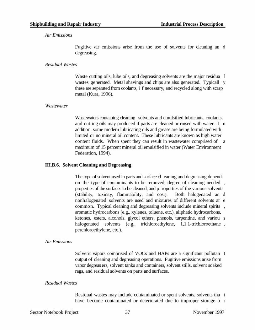
Shipbuilding and Repair Industry Industrial Process Description
Sector Notebook Project November 199737
Air Emissions
Fugitive air emissions arise from the use of solvents for cleaning an ddegreasing.
Residual Wastes
Waste cutting oils, lube oils, and degreasing solvents are the major residua lwastes generated. Metal shavings and chips are also generated. Typicall ythese are separated from coolants, i f necessary, and recycled along with scrapmetal (Kura, 1996).
Wastewater
Wastewaters containing cleaning solvents and emulsified lubricants, coolants,and cutting oils may produced if parts are cleaned or rinsed with water. I naddition, some modern lubricating oils and grease are being formulated withlimited or no mineral oil content. These lubricants are known as high watercontent fluids. When spent they can result in wastewater comprised of amaximum of 15 percent mineral oil emulsified in water (Water EnvironmentFederation, 1994).
III.B.6. Solvent Cleaning and Degreasing
The type of solvent used in parts and surface cl eaning and degreasing dependson the type of contaminants to be removed, degree of cleaning needed ,properties of the surfaces to be cleaned, and p roperties of the various solvents(stability, toxicity, flammability, and cost). Both halogenated an dnonhalogenated solvents are used and mixtures of different solvents ar ecommon. Typical cleaning and degreasing solvents include mineral spirits ,aromatic hydrocarbons (e.g., xylenes, toluene, etc.), aliphatic hydrocarbons,ketones, esters, alcohols, glycol ethers, phenols, turpentine, and variou shalogenated solvents (e.g., trichloroethylene, 1,1,1-trichloroethane ,perchloroethylene, etc.).
Air Emissions
Solvent vapors comprised of VOCs and HAPs are a significant pollutan toutput of cleaning and degreasing operations. Fugitive emissions arise fromvapor degreas ers, solvent tanks and containers, solvent stills, solvent soakedrags, and residual solvents on parts and surfaces.
Residual Wastes
Residual wastes may include contaminated or spent solvents, solvents tha thave become contaminated or deteriorated due to improper storage o r
Shipbuilding and Repair Industry Industrial Process Description
Sector Notebook Project November 199738
handling, solvent residues and sludges from tank bottoms and still bottoms,solvent contaminated rags and filter cartridges, and solvent contaminated soilfrom solvent spills.
Wastewater
Wastewater contain ing solvents are generated when cleaning or rinsing partsor surfaces, and when cleaning equipment, tanks, and process lines wit hwater. Wastewater contamin ated with solvents is also generated when waterfrom diphase parts cleaning operations is replaced.
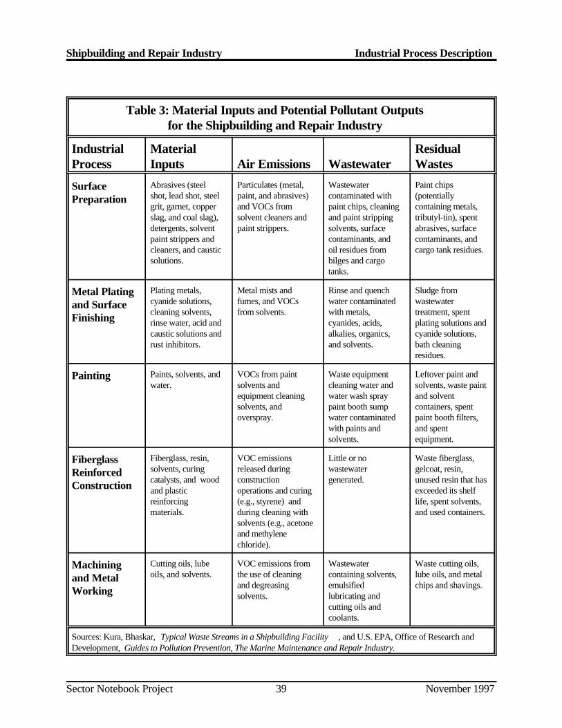
Shipbuilding and Repair Industry Industrial Process Description
Sector Notebook Project November 199739
Table 3: Material Inputs and Potential Pollutant Outputsfor the Shipbuilding and Repair Industry
Industrial Material ResidualProcess Inputs Air Emissions Wastewater Wastes
SurfacePreparation
Abrasives (steel Particulates (metal, Wastewater Paint chipsshot, lead shot, steel paint, and abrasives) contaminated with (potentiallygrit, garnet, copper and VOCs from paint chips, cleaning containing metals,slag, and coal slag), solvent cleaners and and paint stripping tributyl-tin), spentdetergents, solvent paint strippers. solvents, surface abrasives, surfacepaint strippers and contaminants, and contaminants, andcleaners, and caustic oil residues from cargo tank residues.solutions. bilges and cargo
tanks.
Metal Platingand SurfaceFinishing
Plating metals, Metal mists and Rinse and quench Sludge fromcyanide solutions, fumes, and VOCs water contaminated wastewatercleaning solvents, from solvents. with metals, treatment, spentrinse water, acid and cyanides, acids, plating solutions andcaustic solutions and alkalies, organics, cyanide solutions,rust inhibitors. and solvents. bath cleaning
residues.
Painting Paints, solvents, and VOCs from paint Waste equipment Leftover paint andwater. solvents and cleaning water and solvents, waste paint
equipment cleaning water wash spray and solventsolvents, and paint booth sump containers, spentoverspray. water contaminated paint booth filters,
with paints and and spentsolvents. equipment.
FiberglassReinforcedConstruction
Fiberglass, resin, VOC emissions Little or no Waste fiberglass,solvents, curing released during wastewater gelcoat, resin,catalysts, and wood construction generated. unused resin that hasand plastic operations and curing exceeded its shelfreinforcing (e.g., styrene) and life, spent solvents,materials. during cleaning with and used containers.
solvents (e.g., acetoneand methylenechloride).
Machiningand MetalWorking
Cutting oils, lube VOC emissions from Wastewater Waste cutting oils,oils, and solvents. the use of cleaning containing solvents, lube oils, and metal
and degreasing emulsified chips and shavings.solvents. lubricating and
cutting oils andcoolants.
Sources: Kura, Bhaskar, Typical Waste Streams in a Shipbuilding Facility , and U.S. EPA, Office of Research andDevelopment, Guides to Pollution Prevention, The Marine Maintenance and Repair Industry.
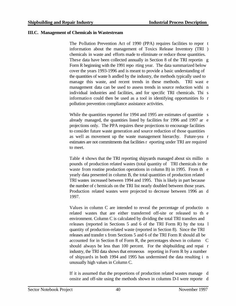
Shipbuilding and Repair Industry Industrial Process Description
Sector Notebook Project November 199740
III.C. Management of Chemicals in Wastestream
The Pollution Prevention Act of 1990 (PPA) requires facilities to repor tinformation about the management of Toxics Release Inventory (TRI )chemicals in waste and efforts made to eliminate or reduce those quantities.These data have been collected annually in Section 8 of the TRI reportin gForm R beginning with the 1991 repo rting year. The data summarized belowcover the years 1993-1996 and is meant to provide a basic understanding ofthe quantities of waste h andled by the industry, the methods typically used tomanage this waste, and recent trends in these methods. TRI wast emanagement data can be used to assess trends in source reduction withi nindividual industries and facilities, and for specific TRI chemicals. Thi sinformation could then be used as a tool in identifying opportunities fo rpollution prevention compliance assistance activities.
While the quantities reported for 1994 and 1995 are estimates of quantitie salready managed, the quantities listed by facilities for 1996 and 1997 ar eprojections only. The PPA requires these projections to encourage facilitiesto consider future waste generation and source reduction of those quantitiesas well as movement up the waste management hierarchy. Future-yea restimates are not commitments that facilities r eporting under TRI are requiredto meet.
Table 4 shows that the TRI reporting shipyards managed about six millio npounds of production related wastes (total quantity of TRI chemicals in thewaste from routine production operations in column B) in 1995. From th eyearly data presented in column B, the total quantities of production relatedTRI wastes increased between 1994 and 1995. This is likely in part becausethe number of c hemicals on the TRI list nearly doubled between those years.Production related wastes were projected to decrease between 1996 an d1997.
Values in column C are intended to reveal the percentage of productio nrelated wastes that are either transferred off-site or released to th eenvironment. Column C is calculated by dividing the total TRI transfers andreleases (reported in Sections 5 and 6 of the TRI Form R) by the tota lquantity of production-related waste (reported in Section 8). Since the TRIreleases and transfer s from Sections 5 and 6 of the TRI Form R should all beaccounted for in Section 8 of Form R, the percentages shown in column Cshould always be less than 100 percent. For the shipbuilding and repai rindustry, the TRI data shows that erroneous reporting in Form R by a numberof shipyards in both 1994 and 1995 has undermined the data resulting i nunusually high values in Column C.
If it is assumed that the proportions of production related wastes manage donsite and off-site using the methods shown in columns D-I were reporte d
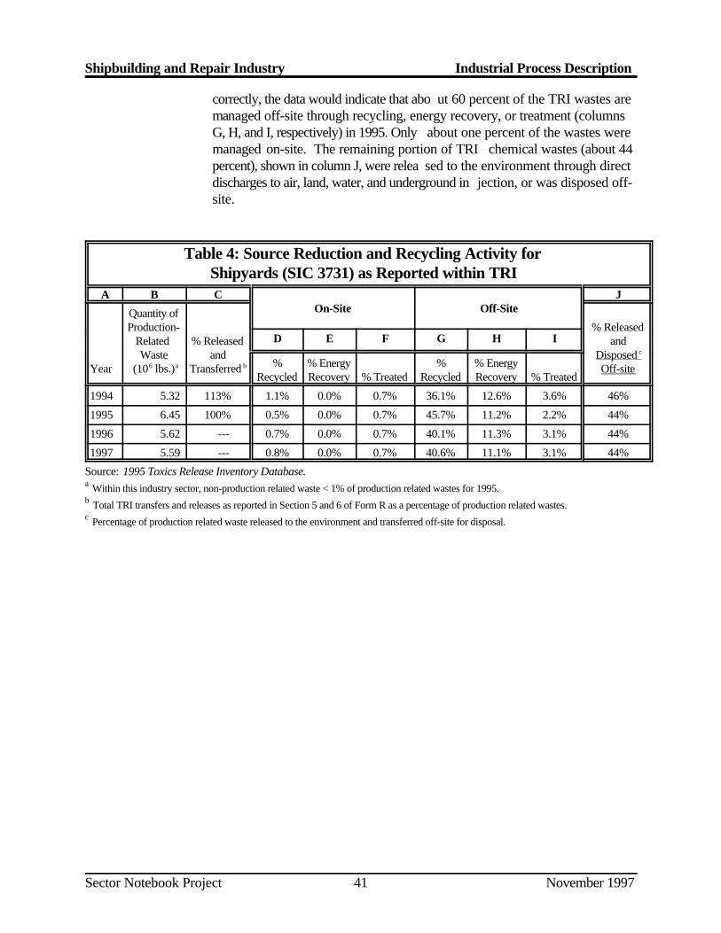
Shipbuilding and Repair Industry Industrial Process Description
Sector Notebook Project November 199741
correctly, the data would indicate that abo ut 60 percent of the TRI wastes aremanaged off-site through recycling, energy recovery, or treatment (columnsG, H, and I, respectively) in 1995. Only about one percent of the wastes weremanaged on-site. The remaining portion of TRI chemical wastes (about 44percent), shown in column J, were relea sed to the environment through directdischarges to air, land, water, and underground in jection, or was disposed off-site.
Table 4: Source Reduction and Recycling Activity forShipyards (SIC 3731) as Reported within TRI
A B C JOn-Site Off-Site
Year (10 lbs.) Transferred Off-site
Quantity ofProduction- % Released
Related % Released andWaste and Disposed
6 a b
c
D E F G H I
% % Energy % % EnergyRecycled Recovery % Treated Recycled Recovery % Treated
1994 5.32 113% 1.1% 0.0% 0.7% 36.1% 12.6% 3.6% 46%
1995 6.45 100% 0.5% 0.0% 0.7% 45.7% 11.2% 2.2% 44%
1996 5.62 --- 0.7% 0.0% 0.7% 40.1% 11.3% 3.1% 44%
1997 5.59 --- 0.8% 0.0% 0.7% 40.6% 11.1% 3.1% 44%
Source: 1995 Toxics Release Inventory Database. Within this industry sector, non-production related waste < 1% of production related wastes for 1995.a
Total TRI transfers and releases as reported in Section 5 and 6 of Form R as a percentage of production related wastes.b
Percentage of production related waste released to the environment and transferred off-site for disposal.c

Shipbuilding and Repair Industry Industrial Process Description
Sector Notebook Project November 199742
Page 42 intentionally left blank.
Shipbuilding and Repair Industry Chemical Releases and Transfers
Sector Notebook Project November 199743
IV. CHEMICAL RELEASE AND TRANSFER PROFILE
This section is designed to provide background information on the pollutantreleases that are reported by this industry. The best source of comparativ epollutant release informat ion is the Toxic Release Inventory (TRI). Pursuantto the Emergency Planning and Community Right-to -Know Act, TRI includesself-reported facility release and transfer data for over 600 toxic chemicals .Facilities within SIC Codes 20 through 39 (manufacturing industries) tha thave more than 10 employees, and that are above weight-based reportin gthresholds are required to report TRI on-site releases and off-site transfers .The information presented within the sector notebooks is derived from th emost recently available (1995) TRI reporting year (which includes over 600chemicals), and focuses primarily on the on-site releases reported by eac hsector. Because TRI requires consistent reporting regardless of sector, it isan excellent tool for drawing comparisons across industries. TRI data providethe type, amount and media receptor of eac h chemical released or transferred.
Although this sector notebook does not present historical informatio nregarding TRI chemical releases over time, please note that in general, toxicchemical releases have been declining. In fact, according to the 1995 ToxicRelease Inventory Public Data Release, reported onsite releases of toxi cchemicals to the environment decreased by 5 percent (85.4 million pounds )between 1994 and 1995 (not including chemicals added and removed from theTRI chemical list during this period). Reported releases dropped by 4 6percent between 1988 and 1995. Rep orted transfers of TRI chemicals to off-site locations increased by 0.4 percent (11.6 million pounds) between 199 4and 1995. More detailed information can be obtained from EPA's annua lToxics Release Inventory Public Data Release book (which is availabl ethrough the EPCRA Hotline at 800-535-0202), or directly from the Toxi cRelease Inventory System database (for user support call 202-260-1531).
Wherever possible, the sector notebooks present TRI data as the primar yindicator of chemical release within each industrial category. TRI dat aprovide the type, amount and media receptor of each chemical released o rtransferred. When other sources of pollutant release data have been obtained,these data have been included to augment the TRI information.
TRI Data Limitations
Certain limitations exist regarding TRI data. Release and transfer reportingare limited to the approximately 600 chemicals on the TRI list. Therefore, alarge portion of the emissions from industrial facilities are not captured b yTRI. Within some sectors, (e.g. dry cleaning, printing and transportatio nequipment cleaning) the major ity of facilities are not subject to TRI reportingbecause they are not considered manufactur ing industries, or because they arebelow TRI report ing thresholds. For these sectors, release information from
Shipbuilding and Repair Industry Chemical Releases and Transfers
Sector Notebook Project November 199744
other sources has been included. In add ition, many facilities report more thanone SIC code reflecting the multiple operation s carried out onsite. Therefore,reported releases and transfers may or may not all be associated with th eindustrial operations described in this notebook.
The reader should also be aware that TRI "pounds released" data presentedwithin the notebooks is not equivalent to a "risk" ranking for each industry.Weighting each pound of release equally does not factor in the relativ etoxicity of each chemical that is released. The Agency is in the process o fdeveloping an approach to assign toxicological weightings to each chemicalreleased so that one can differentiate between pollutants with significan tdifferences in toxicity. As a preliminary ind icator of the environmental impactof the industry's most commonly released chemicals, the notebook briefl ysummarizes the toxicologica l properties of the top five chemicals (by weight)reported by each industry.
Definitions Associated With Section IV Data Tables
General Definitions
SIC Code -- the Standard Industrial Classification (SIC) is a statistica lclassification standard used for all establishment-based Federal economi cstatistics. The SIC codes fa cilitate comparisons between facility and industrydata.
TRI Facilities -- are manufacturing facilities that have 10 or more full-timeemployees and are above established chemical throughput thresholds .Manufacturing facilities are defined as facilities in Standard Industria lClassification primary codes 20-39. Facilities must submit estimates for al lchemicals that are on the EPA's defined list and are above throughpu tthresholds.
Data Table Column Heading Definitions
The following definitions are based upon standard definitions developed b yEPA’s Toxic Release Inventory Program. The ca tegories below represent thepossible pollutant destinations that can be reported.
RELEASES -- are an on-site discharge of a toxic chemical to th eenvironment. This includes emissions to the air, discharges to bodies o fwater, releases at the facility to land, as well as contained disposal int ounderground injection wells.
Releases to Air (Point and Fugitive Air Emissions) -- Include all ai remissions from in dustry activity. Point emissions occur through confined air
Shipbuilding and Repair Industry Chemical Releases and Transfers
Sector Notebook Project November 199745
streams as found in sta cks, vents, ducts, or pipes. Fugitive emissions includeequipment leaks, evaporative losses from surface impoundments and spills ,and releases from building ventilation systems.
Releases to Water (Surface Water Discharges) -- encompass any releasesgoing directly to streams, rivers, lakes, oceans, or other bodies of water .Releases due to runoff, including storm water runoff, are also reportable t oTRI.
Releases to Land -- occur within the boundaries of the reporting facility .Releases to land include disposal of toxic chemicals in landfills, lan dtreatment/application farming, surface i mpoundments, and other land disposalmethods (such as spills, leaks, or waste piles).
Underground Injection -- is a contained release of a fluid into a subsurfacewell for the purpose of waste disposal. Wastes containing TRI chemicals areinjected into either Class I wells or Class V wells. Class I wells are used toinject liquid hazardous wastes or dispose of industrial and municipa lwastewaters beneath the lowermost underground source of drinking water .Class V wells are generally used to inject non-hazardous fluid into or abovean underground source of drinking water. TRI reporting does not currentlydistinguish between these two types of wells, although there are importan tdifferences in en vironmental impact between these two methods of injection.
TRANSFERS -- is a transfer of toxic chemicals in wastes to a facility thatis geographically or physicall y separate from the facility reporting under TRI.Chemicals reported to TRI as transferred are sent to off-site facilities for thepurpose of rec ycling, energy recovery, treatment, or disposal. The quantitiesreported represent a movement of the chemical away from the reportin gfacility. Except for off-site transfers for disposal, the reported quantities d onot necessarily represent entry of the chemical into the environment.
Transfers to POTWs -- are wastewater transferred through pipes or sewersto a publicly owned treatments works (POTW). Treatment or removal of achemical from the wastewater depend on the nature of the chemical, as wellas the treatment methods present at the POTW. Not all TRI chemicals canbe treated or removed by a POTW. Some chemicals, such as metals, may beremoved, but are not destroyed and may be disposed of in landfills o rdischarged to receiving waters.
Transfers to Recycling -- are sent off-site for the purposes of regeneratingor recovery by a variety of recycling methods, including solvent recovery ,metals recovery, and acid regeneration. Once these chemicals have bee nrecycled, they may be returned to the originating f acility or sold commercially.
Shipbuilding and Repair Industry Chemical Releases and Transfers
Sector Notebook Project November 199746
Transfers to Energy Recovery -- are wastes combusted off-site in industrialfurnaces for en ergy recovery. Treatment of a chemical by incineration is notconsidered to be energy recovery.
Transfers to Treatment -- are wastes moved off-site to be treated througha variety of methods, including neutralization, incineration, biologica ldestruction, or physical separation. In some cases, the chemicals are no tdestroyed but prepared for further waste management.
Transfers to Disposal -- are wastes taken to another facility for disposa lgenerally as a release to land or as an injection underground.
Shipbuilding and Repair Industry Chemical Releases and Transfers
Sector Notebook Project November 199747
IV.A. EPA Toxic Release Inventory for the Shipbuilding and Repair Industry
This section summarizes TRI data of shipbuilding and repair facilitie sreporting operations under SIC code 3731. Of the 598 shipbuilding and repairestablishments reported by the 1992 Census of Manufacturers , 43 reportedto TRI in 1995.
According to the 1995 TRI data, the reporting shipbuilding and repai rfacilities released and transferred 39 different TRI chemicals for a total o fapproximately 6.5 million pounds of pollutants during calendar year 1995 .These releases and transfers are dominated by volatile organic compound s(VOCs) and metal-bearing was tes which make up 52 percent and 48 percent,respectively, of total releases and transfers.
Transfers of TRI chemical s account for 58 percent of shipbuilding and repairfacilities’ total TRI-reportable chemicals (3.5 million pounds) while releasesmake up 42 percent (2.5 million pounds).
Releases
Releases to the air, water, and land accounted for 37 percent (2.4 millio npounds) of shipyard’s total reportable chemicals (see Table 5). Of thes ereleases, over 98 percent are released to the air from fugitive (75 percent) orpoint (24 percent) sources. VOCs accounted for about 86 percent of th eshipbuilding and repair industry’s reported TRI releases. The remainder of thereleases were primarily metal-bearing wastes. Xylenes, n-butyl alcohol ,toluene, methyl ethyl ketone, and methyl isobuty l ketone account for about 65percent of the industry’s reported releases. These organic compounds ar etypically found in solvents which are used extensively by the industry i nthinning paints and for cleaning and degreasing metal parts and equipment. Styrene, reported by eight facilities, accounts for about 4 percent of th eindustry’s releases. Styrene comprises a substantial portion of the resi nmixtures and gelcoat used in fiberglass reinforced construction. Finally ,copper-, zinc-, and nickel-be aring wastes account for about 14 percent of theindustry’s reported releases. They are re leased primarily as fugitive emissionsduring metal plating operations and as overspray in painting operations an dcan also be released as fugitive dust emissions during blasting operations.
Transfers
Off-site transfers of TRI chemicals account for 63 percent of shipyard’s totalTRI reportable chemicals (4.1 million pounds). Over 72 percent of th eshipbuilding and rep air industry’s TRI transfers are sent off-site for recyclingfollowed by about 18 percent sent off-site for energy recovery (see Table 6).Metals accounted for about 67 percent of the industry’s reported transfers .VOCs made up almost all of the remainder of transferred TRI chemicals .
Shipbuilding and Repair Industry Chemical Releases and Transfers
Sector Notebook Project November 199748
About 60 percent of the metals transferred were recycled, and almost all o fthe remainder were either treated or disposed off-site. Copper, zinc, an dchromium made up about 70 percent of the metals transferred off-site. Mostof these are in the form of sc rap metal, metal shavings and dust, spent platingbaths, wastewater treatment sludges, and in paint chips and spent blastin gabrasives. About 53 percent of the VOCs transferred were sent off-site forenergy recovery with the remainder primarily going to off-site recycling andtreatment. Waste solvents containing xylene, n-butyl alcohol, methanol ,carbon tetrachloride, and methyl ethyl ketone make up almost 70 percent ofthe VOCs transferred off-site. These wastes were primarily transferred fo renergy recovery.
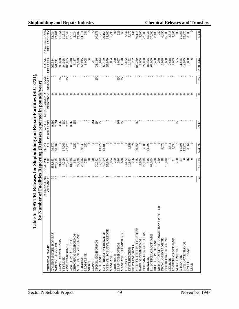
Shipbuilding and Repair Industry Chemical Releases and Transfers
Sector Notebook Project November 199749
Tab
le 5
: 199
5 T
RI
Rel
ease
s fo
r Sh
ipbu
ildin
g an
d R
epai
r F
acili
ties
(SIC
373
1),
by N
umbe
r of
Fac
iliti
es R
epor
ting
(Rel
ease
s re
port
ed in
pou
nds/
year
)
CH
EM
ICA
L N
AM
E#
RE
POR
TIN
GC
HE
MIC
AL
FUG
ITIV
EA
IRPO
INT
AIR
WA
TE
RD
ISC
HA
RG
ES
UN
DE
RG
RO
UN
DIN
JEC
TIO
NL
AN
DD
ISPO
SAL
TO
TA
LR
EL
EA
SES
AV
G. R
EL
EA
SES
PER
FA
CIL
ITY
XY
LE
NE
(MIX
ED
ISO
ME
RS)
3085
3,86
399
,379
9,29
20
096
2,53
432
,084
N-B
UT
YL
AL
CO
HO
L15
278,
218
60,8
022,
691
00
341,
711
22,7
81C
OPP
ER
CO
MPO
UN
DS
891
,410
03,
968
025
095
,628
11,9
54ST
YR
EN
E8
7,20
987
,069
250
00
94,5
2811
,816
ZIN
C C
OM
POU
ND
S6
75,4
1727
,278
2,92
00
250
105,
865
17,6
44Z
INC
(FU
ME
OR
DU
ST)
581
,088
08,
260
00
89,3
4817
,870
CH
RO
MIU
M C
OM
POU
ND
S4
631
7,25
025
60
08,
137
2,03
4M
ET
HY
L E
TH
YL
KE
TO
NE
477
,928
00
00
77,9
2819
,482
TO
LU
EN
E4
25,8
0630
,239
00
056
,045
14,0
11PR
OPY
LE
NE
475
525
00
00
1,00
525
1N
ICK
EL
420
016
00
369
CO
PPE
R4
200
261
00
281
70N
ICK
EL
CO
MPO
UN
DS
330
,592
029
40
250
31,1
3610
,379
ME
TH
AN
OL
32,
172
13,2
2225
00
015
,644
5,21
51,
2,4-
TR
IME
TH
YL
BE
NZ
EN
E3
42,3
9918
,100
00
060
,499
20,1
66M
ET
HY
L IS
OB
UT
YL
KE
TO
NE
355
,979
00
00
55,9
7918
,660
MA
NG
AN
ESE
33,
884
00
00
3,88
41,
295
CH
RO
MIU
M3
260
010
00
270
90L
EA
D C
OM
POU
ND
S2
546
026
10
250
1,05
752
9M
AN
GA
NE
SE C
OM
POU
ND
S2
620
025
00
250
1,12
056
0FR
EO
N 1
132
14,6
720
00
014
,672
7,33
6E
TH
YL
BE
NZ
EN
E2
16,9
931,
159
00
018
,152
9,07
6E
TH
YL
EN
E G
LY
CO
L2
256
260
00
282
141
ME
TH
YL
TE
RT
-BU
TY
L E
TH
ER
242
599
,555
250
00
100,
230
50,1
15B
AR
IUM
CO
MPO
UN
DS
13,
600
00
00
3,60
03,
600
CE
RT
AIN
GL
YC
OL
ET
HE
RS
122
,000
5,00
00
00
27,0
0027
,000
BE
NZ
EN
E1
426
84,9
990
00
85,4
2585
,425
1,1,
1-T
RIC
HL
OR
OE
TH
AN
E1
67,0
000
00
067
,000
67,0
00D
ICH
LO
RO
ME
TH
AN
E1
8,40
00
00
08,
400
8,40
0D
ICH
LO
RO
TE
TR
AFL
UO
RO
ET
HA
NE
(CFC
-114
)1
250
00
00
250
250
DIC
YC
LO
PEN
TA
DIE
NE
118
6,07
20
00
6,09
06,
090
TR
ICH
LO
RO
ET
HY
LE
NE
115
,600
00
00
15,6
0015
,600
CU
ME
NE
17
2,61
10
00
2,61
82,
618
1,2-
DIC
HL
OR
OE
TH
AN
E1
312,
634
00
02,
665
2,66
5A
CR
YL
ON
ITR
ILE
125
05
250
00
505
505
N-H
EX
AN
E1
5711
,608
00
011
,665
11,6
652-
ET
HO
XY
ET
HA
NO
L1
012
,975
00
012
,975
12,9
75C
YC
LO
HE
XA
NE
116
3,86
40
00
3,88
03,
880
LE
AD
10
00
00
00
____
____
____
____
___
____
____
____
___
____
____
____
431,
778,
818
574,
097
29,4
790
1,25
02,
383,
644
55,4
34
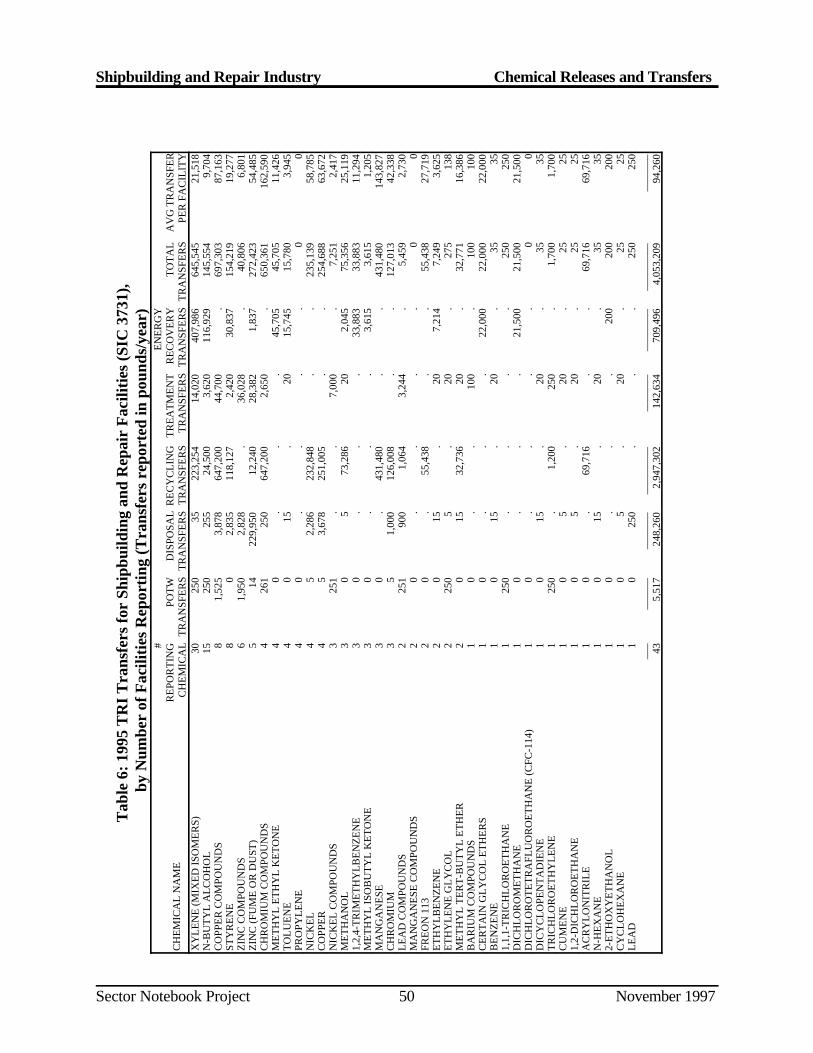
Shipbuilding and Repair Industry Chemical Releases and Transfers
Sector Notebook Project November 199750
Tab
le 6
: 199
5 T
RI
Tra
nsfe
rs fo
r Sh
ipbu
ildin
g an
d R
epai
r F
acili
ties
(SIC
373
1),
by N
umbe
r of
Fac
iliti
es R
epor
ting
(Tra
nsfe
rs r
epor
ted
in p
ound
s/ye
ar)
CH
EM
ICA
L N
AM
E
#R
EPO
RT
ING
CH
EM
ICA
LPO
TW
TR
AN
SFE
RS
DIS
POSA
LT
RA
NSF
ER
SR
EC
YC
LIN
GT
RA
NSF
ER
ST
RE
AT
ME
NT
TR
AN
SFE
RS
EN
ER
GY
RE
CO
VE
RY
TR
AN
SFE
RS
TO
TA
LT
RA
NSF
ER
SA
VG
TR
AN
SFE
RPE
R F
AC
ILIT
YX
YL
EN
E (M
IXE
D IS
OM
ER
S)30
250
3522
3,25
414
,020
407,
986
645,
545
21,5
18N
-BU
TY
L A
LC
OH
OL
1525
025
524
,500
3,62
011
6,92
914
5,55
49,
704
CO
PPE
R C
OM
POU
ND
S8
1,52
53,
878
647,
200
44,7
00.
697,
303
87,1
63ST
YR
EN
E8
02,
835
118,
127
2,42
030
,837
154,
219
19,2
77Z
INC
CO
MPO
UN
DS
61,
950
2,82
8.
36,0
28.
40,8
066,
801
ZIN
C (F
UM
E O
R D
UST
)5
1422
9,95
012
,240
28,3
821,
837
272,
423
54,4
85C
HR
OM
IUM
CO
MPO
UN
DS
426
125
064
7,20
02,
650
.65
0,36
116
2,59
0M
ET
HY
L E
TH
YL
KE
TO
NE
40
..
.45
,705
45,7
0511
,426
TO
LU
EN
E4
015
.20
15,7
4515
,780
3,94
5PR
OPY
LE
NE
40
..
..
00
NIC
KE
L4
52,
286
232,
848
..
235,
139
58,7
85C
OPP
ER
45
3,67
825
1,00
5.
.25
4,68
863
,672
NIC
KE
L C
OM
POU
ND
S3
251
..
7,00
0.
7,25
12,
417
ME
TH
AN
OL
30
573
,286
202,
045
75,3
5625
,119
1,2,
4-T
RIM
ET
HY
LB
EN
ZE
NE
30
..
.33
,883
33,8
8311
,294
ME
TH
YL
ISO
BU
TY
L K
ET
ON
E3
0.
..
3,61
53,
615
1,20
5M
AN
GA
NE
SE3
0.
431,
480
..
431,
480
143,
827
CH
RO
MIU
M3
51,
000
126,
008
..
127,
013
42,3
38L
EA
D C
OM
POU
ND
S2
251
900
1,06
43,
244
.5,
459
2,73
0M
AN
GA
NE
SE C
OM
POU
ND
S2
0.
..
.0
0FR
EO
N 1
132
0.
55,4
38.
.55
,438
27,7
19E
TH
YL
BE
NZ
EN
E2
015
.20
7,21
47,
249
3,62
5E
TH
YL
EN
E G
LY
CO
L2
250
5.
20.
275
138
ME
TH
YL
TE
RT
-BU
TY
L E
TH
ER
20
1532
,736
20.
32,7
7116
,386
BA
RIU
M C
OM
POU
ND
S1
0.
.10
0.
100
100
CE
RT
AIN
GL
YC
OL
ET
HE
RS
10
..
.22
,000
22,0
0022
,000
BE
NZ
EN
E1
015
.20
.35
351,
1,1-
TR
ICH
LO
RO
ET
HA
NE
125
0.
..
.25
025
0D
ICH
LO
RO
ME
TH
AN
E1
0.
..
21,5
0021
,500
21,5
00D
ICH
LO
RO
TE
TR
AFL
UO
RO
ET
HA
NE
(CFC
-114
)1
0.
..
.0
0D
ICY
CL
OPE
NT
AD
IEN
E1
015
.20
.35
35T
RIC
HL
OR
OE
TH
YL
EN
E1
250
.1,
200
250
.1,
700
1,70
0C
UM
EN
E1
05
.20
.25
251,
2-D
ICH
LO
RO
ET
HA
NE
10
5.
20.
2525
AC
RY
LO
NIT
RIL
E1
0.
69,7
16.
.69
,716
69,7
16N
-HE
XA
NE
10
15.
20.
3535
2-E
TH
OX
YE
TH
AN
OL
10
..
.20
020
020
0C
YC
LO
HE
XA
NE
10
5.
20.
2525
LE
AD
10
250
..
.25
025
0__
___
____
____
___
____
____
___
____
___
____
____
____
___
____
___
435,
517
248,
260
2,94
7,30
214
2,63
470
9,49
64,
053,
209
94,2
60
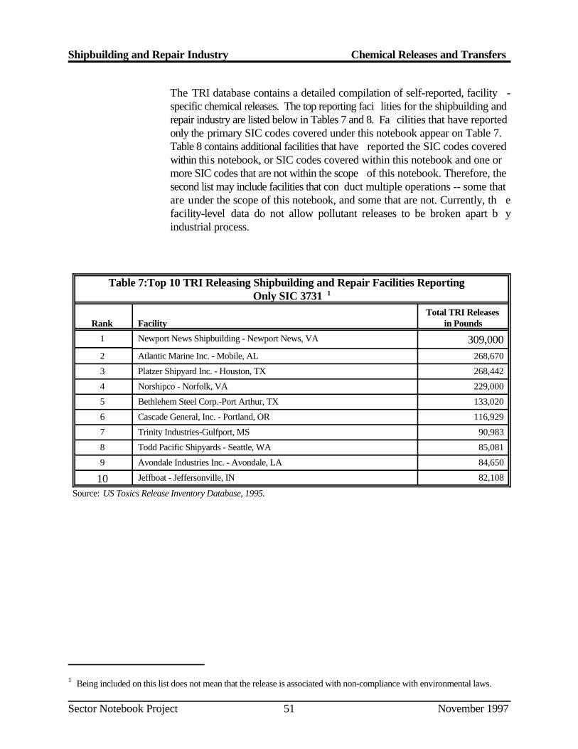
Shipbuilding and Repair Industry Chemical Releases and Transfers
Being included on this list does not mean that the release is associated with non-compliance with environmental laws.1
Sector Notebook Project November 199751
The TRI database contains a detailed compilation of self-reported, facility -specific chemical releases. The top reporting faci lities for the shipbuilding andrepair industry are listed below in Tables 7 and 8. Fa cilities that have reportedonly the primary SIC codes covered under this notebook appear on Table 7.Table 8 contains additional facilities that have reported the SIC codes coveredwithin this notebook, or SIC codes covered within this notebook and one ormore SIC codes that are not within the scope of this notebook. Therefore, thesecond list may include facilities that con duct multiple operations -- some thatare under the scope of this notebook, and some that are not. Currently, th efacility-level data do not allow pollutant releases to be broken apart b yindustrial process.
Table 7:Top 10 TRI Releasing Shipbuilding and Repair Facilities ReportingOnly SIC 3731 1
Rank Facility in PoundsTotal TRI Releases
1 Newport News Shipbuilding - Newport News, VA 309,0002 Atlantic Marine Inc. - Mobile, AL 268,670
3 Platzer Shipyard Inc. - Houston, TX 268,442
4 Norshipco - Norfolk, VA 229,000
5 Bethlehem Steel Corp.-Port Arthur, TX 133,020
6 Cascade General, Inc. - Portland, OR 116,929
7 Trinity Industries-Gulfport, MS 90,983
8 Todd Pacific Shipyards - Seattle, WA 85,081
9 Avondale Industries Inc. - Avondale, LA 84,650
10 Jeffboat - Jeffersonville, IN 82,108
Source: US Toxics Release Inventory Database, 1995.
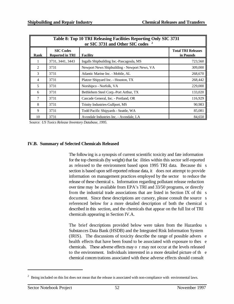
Shipbuilding and Repair Industry Chemical Releases and Transfers
Being included on this list does not mean that the release is associated with non-compliance with enviromental laws.2
Sector Notebook Project November 199752
Table 8: Top 10 TRI Releasing Facilities Reporting Only SIC 3731 or SIC 3731 and Other SIC codes 2
Rank Reported in TRI Facility in PoundsSIC Codes Total TRI Releases
1 3731, 3441, 3443 Ingalls Shipbuilding Inc.-Pascagoula, MS 723,560
2 3731 Newport News Shipbuilding - Newport News, VA 309,000
3 3731 Atlantic Marine Inc. - Mobile, AL 268,670
4 3731 Platzer Shipyard Inc. - Houston, TX 268,442
5 3731 Norshipco - Norfolk, VA 229,000
6 3731 Bethlehem Steel Corp.-Port Arthur, TX 133,020
7 3731 Cascade General, Inc. - Portland, OR 116,929
8 3731 Trinity Industries-Gulfport, MS 90,983
9 3731 Todd Pacific Shipyards - Seattle, WA 85,081
10 3731 Avondale Industries Inc. - Avondale, LA 84,650 Source: US Toxics Release Inventory Database, 1995.
IV.B. Summary of Selected Chemicals Released
The following is a synopsis of current scientific toxicity and fate informationfor the top chemicals (by weight) that fac ilities within this sector self-reportedas released to the environment based upon 1995 TRI data. Because thi ssection is based upon self-reported release data, it does not attempt to provideinformation on management practices employed by the sector to reduce therelease of these chemical s. Information regarding pollutant release reductionover time may be available from EPA’s TRI and 33/50 programs, or directlyfrom the industrial trade associations that are listed in Section IX of thi sdocument. Since these descriptions are cursory, please consult the source sreferenced below for a more detailed description of both the chemical sdescribed in this section, and the chemicals that appear on the full list of TRIchemicals appearing in Section IV.A.
The brief descriptions provided below were taken from the Hazardou sSubstances Data Bank (HSDB) and the Integrated Risk Information System(IRIS). The discussions of toxicity describe the range of possible advers ehealth effects that have been found to be associated with exposure to thes echemicals. These adverse effects may o r may not occur at the levels releasedto the environment. Individuals interested in a more detailed picture of th echemical concen trations associated with these adverse effects should consult
Shipbuilding and Repair Industry Chemical Releases and Transfers
TOXNET is a computer system run by the National Library of Medicine that includes a number of toxicological3
databases managed by EPA, National Cancer Institute, and the National Institute for Occupational Safety and Health.For more information on TOXNET, contact the TOXNET help line at 800-231-3766. Databases included in TOXNETare: CCRIS (Chemical Carcinogenesis Research Information System), DART (Developmental and ReproductiveToxicity Database), DBIR (Directory of Biotechnology Information Resources), EMICBACK (Environmental MutagenInformation Center Backfile), GENE-TOX (Genetic Toxicology), HSDB (Hazardous Substances Data Bank), IRIS(Integrated Risk Information System), RTECS (Registry of Toxic Effects of Chemical Substances), and TRI (ToxicChemical Release Inventory). HSDB contains chemical-specific information on manufacturing and use, chemical andphysical properties, safety and handling, toxicity and biomedical effects, pharmacology, environmental fate and exposurepotential, exposure standards and regulations, monitoring and analysis methods, and additional references.
Sector Notebook Project November 199753
a toxicologist or the toxicity literature for the chemical to obtain mor einformation. The effects listed below must be taken in context of thes eexposure assumptions that are more fully explained within the full chemica lprofiles in HSDB. For more information on TOXNET , contact th e3
TOXNET help line at 1-800-231-3766.
Xylenes (Mixed Isomers) (CAS: 1330-20-7)
Sources. Xylenes are used extensively as cleaning solvents and in thinnin gpaints.
Toxicity. Xylenes are rapidly absorbed into the body after inhalation ,ingestion, or skin contact. Short-term exposure of humans to high levels ofxylene can cause irritation of the skin, eyes, nose, and throat, difficulty i nbreathing, impaired lung function, impaired memory, and possible changes inthe liver and kidneys. Both short- and long-term exposure to hig hconcentrations can cause eff ects such as headaches, dizziness, confusion, andlack of muscle co ordination. Reactions of xylene (see environmental fate) inthe atmosphere contribute to the formation o f ozone in the lower atmosphere.Ozone can affect the respiratory system, especially in sensitive individual ssuch as asthma or allergy sufferers.
Carcinogenicity. There is currently no evidence to suggest that this chemicalis carcinogenic.
Environmental Fate. A portion of releases to land and water will quickl yevaporate, although some degradation by microorganisms will occur. Xylenesare moderately mobile in soils and may leach into groundwater, where the ymay persist for several years. Xylenes are volatile organic chemicals. A ssuch, xylene in the lower atmosphere will react with other atmospheri ccomponents, contributing to the formation of ground-level ozone and otherair pollutants.
Shipbuilding and Repair Industry Chemical Releases and Transfers
Sector Notebook Project November 199754
Zinc and Zinc Compounds (CAS: 7440-66-6; 20-19-9)
Sources. To protect metal from oxidizing, it is often coated with a materialthat will protect it from moisture and air. In the galvanizing process, steel iscoated with zinc.
Toxicity. Zinc is a nutritional trace element; toxicity from ingestion is low.Severe exposure to zinc might give rise to gastritis with vomiting due toswallowing of zinc dusts. Short-term exposure to very high levels of zinc islinked to lethargy, dizziness, nausea, fever, diarrhea, and reversiblepancreatic and neurological damage. Long-term zinc poisoning causesirritability, muscular stiffness and pain, loss of appetite, and nausea.
Zinc chloride fumes cause injury to mucous membranes and to the skin.Ingestion of soluble zinc salts may cause nausea, vomiting, and purging.
Carcinogenicity. There is currently no evidence to suggest that thischemical is carcinogenic.
Environmental Fate. Significant zinc contamination of soil is only seen inthe vicinity of industrial point sources. Zinc is a relatively stable soft metal,though burns in air. Zinc bioconcentrates in aquatic organisms.
n-Butanol (n-Butyl Alcohol) (CAS: 71-36-3)
Sources. n-Butanol is used extensively for thinning paints and equipmen tcleaning.
Toxicity. Short-term exposure usually results in depression of the centra lnervous system, hypotension, nausea, vomiting, and diarrhea. Butanols maycause gastrointestinal hemorrhaging. Eye contact may cause burning an dblurred vision. Hyp otension and cardiac arrhythmias may occur. Inhaling n-butanol may cause pulmonary edema. Headache, dizziness, and giddiness mayoccur. Liver injury may occur but is probably rare. Dermatitis an dhypoglycemia may result from exposure to this chemical. Chronic exposuremay result in dry, cracked skin, and eye inflammation. Workers hav eexhibited systemic effects of the auditory nerve as well as vestibular injury.
Carcinogenicity. There are currently no long-term studies in humans o ranimals to suggest that this chemic al is carcinogenic. Based on this evidence,U.S. EPA has indicated that this ch emical cannot be classified as to its humancarcinogenicity. There is some evidence of chromosomal abnormalities i nshort-term tests in bacteria and hamster cells, which may suggest potentia lcarcinogenicity.
Shipbuilding and Repair Industry Chemical Releases and Transfers
Sector Notebook Project November 199755
Environmental Fate. This chemical may volatilize from soil surface. I naddition, the chemical may biodegrade from the soil, and leach t ogroundwater. n-Butanol released to water is expected to biodegrade an dvolatilize from the water surface, and is not expected to bioconcentrate in fish.People are exposed primarily from contact with products containing n -butanol.
Copper and Copper Compounds (CAS: 7440-50-8)
Sources. Copper and copper compounds are commonly used as biocides inanti-fouling paints. Many ship parts requiring anti-corrosive characteristic s(e.g., piping) are fabricated or plated with copper and copper alloys.
Toxicity. Metallic copper probably has little or no toxicity, although coppersalts are more toxic. Inhalation of copper oxide fumes and dust has bee nshown to cause metal fume fever, irritation of the upper respiratory tract ,nausea, sneezing, coughing, chills, aching muscles, gastric pain, and diarrhea.However, the respira tory symptoms may be due to a non-specific reaction tothe inhaled dust as a foreign body in the lung, and the gastrointestina lsymptoms may be attributed to the conversion of copper to copper salts in thebody.
It is unclear whether long-term copper poisoning exists in humans. Som ehave related ce rtain central nervous system disorders, such as giddiness, lossof appetite, excessive perspiration, and drowsiness to copper poisoning .Long-term exposure to copper may also cause hair, skin, and teet hdiscoloration, apparently without other adverse effects.
People at special risk from exposure to copper include those with impaire dpulmonary function, especially those with obstructive airway diseases, sincethe breathing of copper fumes might cause exacerbation of pre-existin gsymptoms due to its irritant properties.
Ecologically, copper is a trace element essential to many plants and animals.However, high levels of copper in soil can be directly toxic to certain soi lmicroorganisms and can disrupt importan t microbial processes in soil, such asnitrogen and phosphorus cycling.
Carcinogenicity. There is currently no evidence to suggest that this chemicalis carcinogenic.
Environmental Fate. Copper is typically fou nd in the environment as a solidmetal in soils and soil sediment in surface water. There is no evidence tha tbiotransformation processes have a significant bearing on the fate an dtransport of copper in water.
Shipbuilding and Repair Industry Chemical Releases and Transfers
Sector Notebook Project November 199756
Styrene (CAS: 100-42-5)
Sources. Styrene is a major constituent of fiberglass resins and gelcoats.
Toxicity. Short-term exposure may cause irritation to eyes, lungs, stomach,and skin. Problems may occur in the central nervous system as a result o fserious exposure and may also occur in the peri pheral nervous system. Short-term exposure from inhalation is commonly associated with “styren esickness”, which includes vomiting, loss of appetite, and a drunken feeling .Short-term exposure also irrita tes the respiratory tract, and is associated withasthma and pulmonary edema.
Long-term exposure in those working with styrene has been associated withimpaired nervous system functions including memory, learning, and moto rskills and impaired psychiatric functioning. Styrene may also cause gen emutations and birth defects. Styrene has been shown to cause liver damage.
Carcinogenicity. The International Agency for Research on Cancer notesthat evidence of carcinogenicity in experimental animals indicates that styreneis a possible carcinogen in humans. However, U.S. EPA is currentl yreviewing the evidence for carcinogenicity of styrene, and may arrive at adifferent decision.
Environmental Fate and Potential for Human Exposure. If styrene i sreleased to air, it will quickly react with hydroxyl radicals and ozone. A tnight, air concentrations of styrene will degrade by reacting with nitrat eradicals. Sty rene released to water volatilizes and biodegrades, but does nothydrolyze. In soil, styrene biode grades and is fairly immobile in soil. Styrenehas been found in drinking water, but not in 945 groundwater supplies. Thechemical has been found in industrial effluents and in a ir surrounding industrialsources and in urban areas. The chemical has been found in some foo dpackaged in polystyrene containers.
Shipbuilding and Repair Industry Chemical Releases and Transfers
Sector Notebook Project November 199757
IV.C. Other Data Sources
The toxic chemical release data o btained from TRI captures only about sevenpercent of the facilities in the shipbuilding and repair industry. However, i tallows for a comparison across years and industry sectors. Reporte dchemicals are limited to the approximately 600 TRI chemicals. A larg eportion of the em issions from shipbuilding and repair facilities, therefore, arenot captured by TRI. The EPA Office of Air Quality Planning and Standardshas compiled air pollutant emission factors for determining the total ai remissions of priority pollutants (e.g., total hydrocarbons, SOx, NOx, CO ,particulates, etc.) from many shipbuilding and repair sources.
The Aerometric Information Retrieval System (AIRS) contains a wide rangeof information related to stationary sources of air pollution, including th eemissions of a number of air pollutants which may be of concern within aparticular industry. With the exception of volatile organic compound s(VOCs), there is little ov erlap with the TRI chemicals reported above. Table9 summarizes annual releases (from the industries for which a Secto rNotebook Profile was prepared) of carbon monoxide (CO), nitrogen dioxide(NO ), particulate matter of 10 microns or less (PM10), total particulat e2
matter (PT), sulfur dioxide (SO ), and volatile organic compounds (VOCs).2
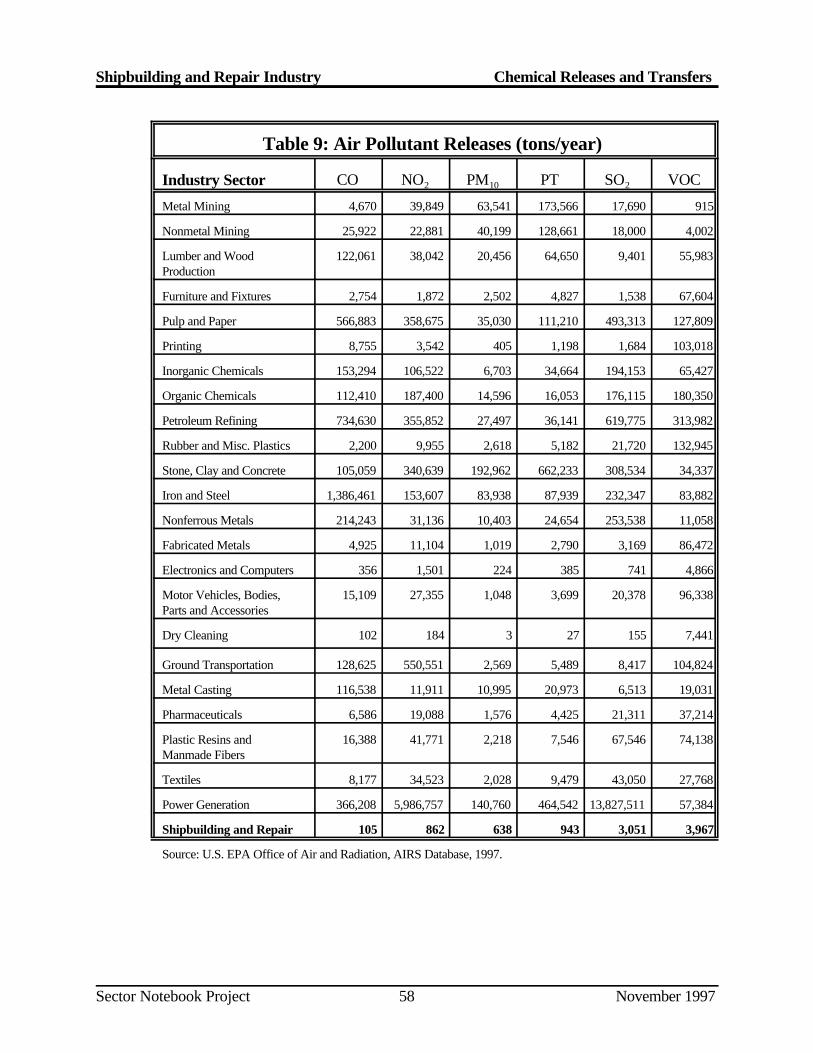
Shipbuilding and Repair Industry Chemical Releases and Transfers
Sector Notebook Project November 199758
Table 9: Air Pollutant Releases (tons/year)
Industry Sector CO NO PM PT SO VOC2 10 2
Metal Mining 4,670 39,849 63,541 173,566 17,690 915
Nonmetal Mining 25,922 22,881 40,199 128,661 18,000 4,002
Lumber and Wood 122,061 38,042 20,456 64,650 9,401 55,983Production
Furniture and Fixtures 2,754 1,872 2,502 4,827 1,538 67,604
Pulp and Paper 566,883 358,675 35,030 111,210 493,313 127,809
Printing 8,755 3,542 405 1,198 1,684 103,018
Inorganic Chemicals 153,294 106,522 6,703 34,664 194,153 65,427
Organic Chemicals 112,410 187,400 14,596 16,053 176,115 180,350
Petroleum Refining 734,630 355,852 27,497 36,141 619,775 313,982
Rubber and Misc. Plastics 2,200 9,955 2,618 5,182 21,720 132,945
Stone, Clay and Concrete 105,059 340,639 192,962 662,233 308,534 34,337
Iron and Steel 1,386,461 153,607 83,938 87,939 232,347 83,882
Nonferrous Metals 214,243 31,136 10,403 24,654 253,538 11,058
Fabricated Metals 4,925 11,104 1,019 2,790 3,169 86,472
Electronics and Computers 356 1,501 224 385 741 4,866
Motor Vehicles, Bodies, 15,109 27,355 1,048 3,699 20,378 96,338Parts and Accessories
Dry Cleaning 102 184 3 27 155 7,441
Ground Transportation 128,625 550,551 2,569 5,489 8,417 104,824
Metal Casting 116,538 11,911 10,995 20,973 6,513 19,031
Pharmaceuticals 6,586 19,088 1,576 4,425 21,311 37,214
Plastic Resins and 16,388 41,771 2,218 7,546 67,546 74,138Manmade Fibers
Textiles 8,177 34,523 2,028 9,479 43,050 27,768
Power Generation 366,208 5,986,757 140,760 464,542 13,827,511 57,384
Shipbuilding and Repair 105 862 638 943 3,051 3,967
Source: U.S. EPA Office of Air and Radiation, AIRS Database, 1997.
Shipbuilding and Repair Industry Chemical Releases and Transfers
Sector Notebook Project November 199759
IV.D. Comparison of Toxic Release Inventory Between Selected Industries
The following information is presented as a comparison of pollutant releaseand transfer data across in dustrial categories. It is provided to give a generalsense as to the relative scale of TRI releases and transfers within each sectorprofiled under this project. Please note that the following figure and table donot contain releases and transfers for industrial categories that are no tincluded in this project, and thus cannot be used to draw conclusion sregarding the total release and transfer amounts that are reported to TRI .Similar information is available within the annual TRI Public Data Releas eBook.
Figure 10 is a graphical representation of a summary of the 1995 TRI data forthe shipbuilding an d repair industry and the other sectors profiled in separatenotebooks. The bar graph presents the total TRI releases and total transferson the vertical axis. T he graph is based on the data shown in Table 10 and ismeant to facilitate comparisons between the relative amounts of releases ,transfers, and releases per f acility both within and between these sectors. Thereader should note, however, that differences in the proportion of facilitie scaptured by TRI exist betwe en industry sectors. This can be a factor of poorSIC matching and relative differences in the number of facilities reporting toTRI from the various sectors. In the case of the shipbuilding and repai rindustry, the 1995 TRI data presented here covers 43 fa cilities. These facilitieslisted SIC 3731 (Shipbuilding and Repair) as primary SIC codes.
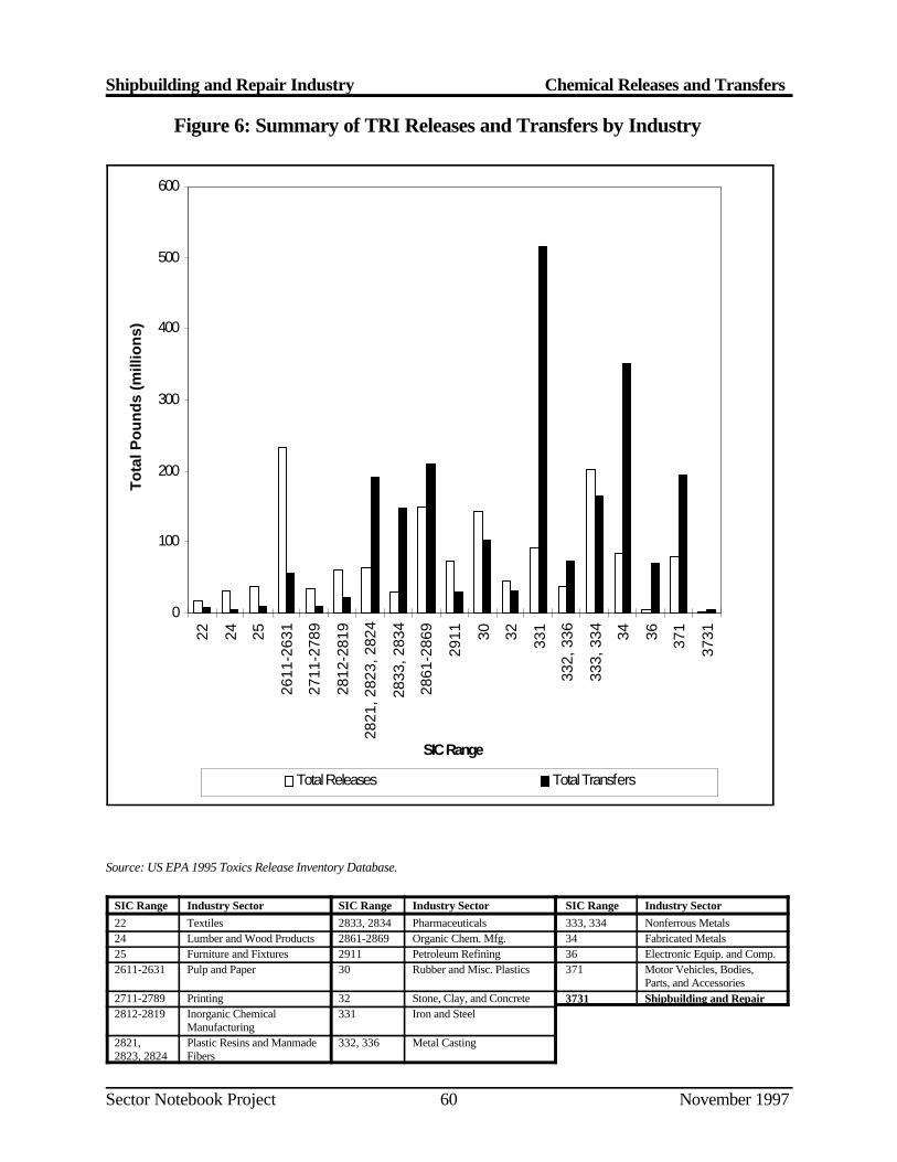
0
100
200
300
400
500
60022 24 25
2611
-263
1
2711
-278
9
2812
-281
9
2821
, 282
3, 2
824
2833
, 283
4
2861
-286
9
2911 30 32 331
332,
336
333,
334 34 36 371
3731
SIC Range
To
tal P
ou
nd
s (m
illio
ns)
Total Releases Total Transfers
Shipbuilding and Repair Industry Chemical Releases and Transfers
Sector Notebook Project November 199760
Figure 6: Summary of TRI Releases and Transfers by Industry
Source: US EPA 1995 Toxics Release Inventory Database.
SIC Range Industry Sector SIC Range Industry Sector SIC Range Industry Sector22 Textiles 2833, 2834 Pharmaceuticals 333, 334 Nonferrous Metals24 Lumber and Wood Products 2861-2869 Organic Chem. Mfg. 34 Fabricated Metals25 Furniture and Fixtures 2911 Petroleum Refining 36 Electronic Equip. and Comp.2611-2631 Pulp and Paper 30 Rubber and Misc. Plastics 371 Motor Vehicles, Bodies,
Parts, and Accessories2711-2789 Printing 32 Stone, Clay, and Concrete 3731 Shipbuilding and Repair2812-2819 Inorganic Chemical 331 Iron and Steel
Manufacturing2821, Plastic Resins and Manmade 332, 336 Metal Casting2823, 2824 Fibers
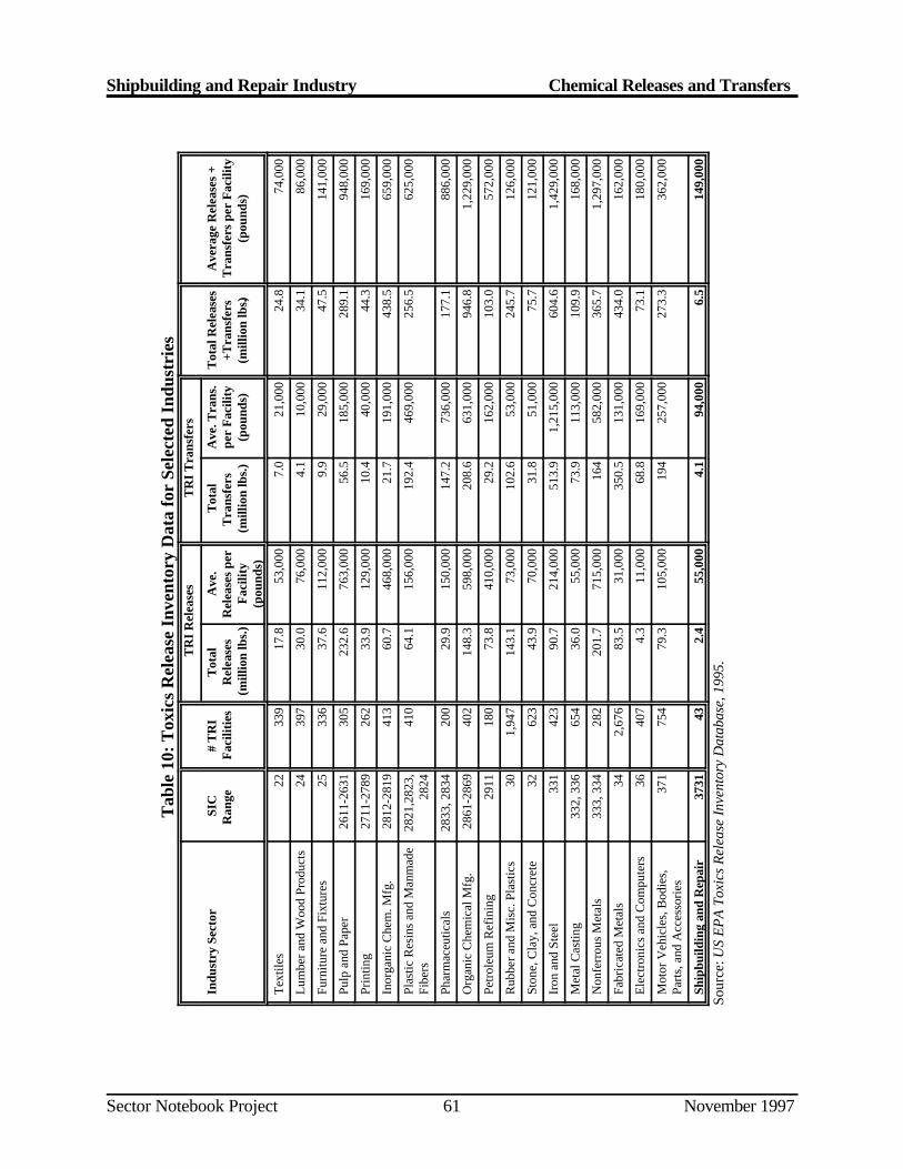
Shipbuilding and Repair Industry Chemical Releases and Transfers
Sector Notebook Project November 199761
Tab
le 1
0: T
oxic
s R
elea
se I
nven
tory
Dat
a fo
r Se
lect
ed I
ndus
trie
sT
RI
Rel
ease
sT
RI
Tra
nsfe
rs
Indu
stry
Sec
tor
SIC
Ran
ge
# T
RI
Fac
iliti
esT
otal
Rel
ease
s(m
illio
n lb
s.)
Ave
.R
elea
ses
per
Fac
ility
(pou
nds)
Tot
alT
rans
fers
(mill
ion
lbs.
)
Ave
. Tra
ns.
per
Fac
ility
(pou
nds)
Tot
al R
elea
ses
+Tra
nsfe
rs(m
illio
n lb
s.)
Ave
rage
Rel
ease
s +
Tra
nsfe
rs p
er F
acili
ty(p
ound
s)
Tex
tiles
2233
917
.853
,000
7.0
21,
000
24.8
74,0
00
Lum
ber a
nd W
ood
Prod
ucts
2439
730
.076
,000
4.1
10,0
0034
.186
,000
Furn
iture
and
Fix
ture
s25
336
37.6
112,
000
9.9
29,0
0047
.514
1,00
0
Pulp
and
Pap
er26
11-2
631
305
232.
676
3,00
056
.518
5,00
028
9.1
948,
000
Prin
ting
2711
-278
926
233
.912
9,00
010
.440
,000
44.3
169,
000
Inor
gani
c C
hem
. Mfg
.28
12-2
819
413
60.7
468,
000
21.7
191,
000
438.
565
9,00
0
Plas
tic R
esin
s an
d M
anm
ade
Fibe
rs28
21,2
823,
2824
410
64.1
156,
000
192.
446
9,00
025
6.5
625,
000
Phar
mac
eutic
als
2833
, 283
420
029
.915
0,00
014
7.2
736,
000
177.
188
6,00
0
Org
anic
Che
mic
al M
fg.
2861
-286
940
214
8.3
598,
000
208.
663
1,00
094
6.8
1,22
9,00
0
Petr
oleu
m R
efin
ing
2911
180
73.8
410,
000
29.2
162,
000
103.
057
2,00
0
Rub
ber a
nd M
isc.
Pla
stic
s30
1,94
714
3.1
73,0
0010
2.6
53,0
0024
5.7
126,
000
Ston
e, C
lay,
and
Con
cret
e32
623
43.9
70,0
0031
.851
,000
75.7
121,
000
Iron
and
Ste
el33
142
390
.721
4,00
051
3.9
1,21
5,00
060
4.6
1,42
9,00
0
Met
al C
astin
g33
2, 3
3665
436
.055
,000
73.9
113,
000
109.
916
8,00
0
Non
ferr
ous
Met
als
333,
334
282
201.
771
5,00
016
458
2,00
036
5.7
1,29
7,00
0
Fabr
icat
ed M
etal
s34
2,67
683
.531
,000
350.
513
1,00
043
4.0
162,
000
Ele
ctro
nics
and
Com
pute
rs36
407
4.3
11,0
0068
.816
9,00
073
.118
0,00
0
Mot
or V
ehic
les,
Bod
ies,
Part
s, a
nd A
cces
sori
es37
175
479
.310
5,00
019
425
7,00
027
3.3
362,
000
Ship
build
ing
and
Rep
air
3731
432.
455
,000
4.1
94,0
006.
514
9,00
0
Sour
ce: U
S EP
A To
xics
Rel
ease
Inve
ntor
y D
atab
ase,
199
5.
Shipbuilding and Repair Industry Chemical Releases and Transfers
Sector Notebook Project November 199762
Page 62 intentionally left blank.
Shipbuilding and Repair Pollution Prevention Opportunities
Sector Notebook Project November 199763
V. POLLUTION PREVENTION OPPORTUNITIES
The best way to reduce pollution is to prevent it in the first place. Som ecompanies have creatively implemented pollution prevention techniques thatimprove efficiency and increase profits while at the same time minimizin genvironmental impacts. This can be done in many ways such as reducin gmaterial inputs, re-engineering processes to reuse by-products, improvin gmanagement practices, and employing substitution of toxic chemicals. Somesmaller facilities are able to actually get below regulatory thresholds just b yreducing pollutant releases through aggressive pollution prevention policies.
The Pollution Prevention Act of 1990 established a national policy o fmanaging waste through source reduction, which means preventing th egeneration of waste. The Pollution Prevention Act also established as nationalpolicy a hierarchy of waste management options for s ituations in which sourcereduction cannot be implemented feasibly. In the waste managemen thierarchy, if source reduction is not feasible the next alternative is recyclingof wastes, followed by energy recovery, and waste treatment as a las talternative.
In order to encourage these approaches, this section provides both genera land company-specific descriptions of some pollu tion prevention advances thathave been implemented within the shipbu ilding and repair industry. While thelist is not exhaustive, it d oes provide core information that can be used as thestarting point for facilities interested in beginning their own pollutio nprevention projects. This section provides summary information fro mactivities that may be, or are being implemented by this sector. Whe npossible, information is provided that gives the context in which the techniquecan be used effectively. Please note that the ac tivities described in this sectiondo not necessarily apply to all facilities that fall within this sector. Facility -specific conditions must be carefully considered when pollution preventio noptions are evaluated, and the full impacts of the change must examine howeach option affects air, land and water pollutant releases.
Much of the information contained in this Section was obtained fro mHazardous Waste Minimization Guide for Shipyards , produced by th eNational Shipbuilding Research Program (NSRP) in cooperat ion with the U.S.Navy and National Steel and Shipbuilding Company (NASSCO). The Guideprovides and extensive discussion of pollution prevention opportunitie savailable to shipyards which could not all be reproduced in this document .For further details on pollution prevention opportu nities for shipyards, readersare encouraged to consult the Guide and the additional references listed i nSection IX of this sector notebook. In addition, many of the pollutio nprevention opportunities listed in the Profile of the Fabricated Meta lProducts Industry Sector Notebook can also be applied to the shipbuilding andrepair industry.
Shipbuilding and Repair Pollution Prevention Opportunities
Sector Notebook Project November 199764
V.A. Surface Preparation
The majority of wastes generated during surface preparation are spen tabrasives mixed with paint chips. One way the volume of waste generated canbe reduced is by using blast media that is relatively easy to reuse. Som eabrasives, such as mineral abrasives, are not easily reused. Copper slag hasa very low reuse factor and in general , can be used no more than twice beforebreaking down.
Steel Shot and Grit
One of the most widely used reusable abrasives is steel grit, which is a crushedform of steel shot. While slags and sands can only be used a couple of times,steel abrasives can be used 50 ti mes or more. With reused steel abrasive, caremust be taken to watch that the abrasive does not become rounded. Th eabrasive works best if it has a sharp angul ar shape. Steel shot and grit requirea high initial outlay of capital, but they can be used r epeatedly to the point thatthey are more cost effective than copper slag. This medium is only deeme dhazardous when it is contaminated with a sufficient amount of paint chips.
Improving Recyclability of Abrasive Blasting Media
In order to realize the maximum usage of reusable grit, measures must b etaken to ensure it can be reused. Some media, such as steel shot, can b ereused hundreds of times. It is important that the used grit is recovered a smuch as possible. With wheelabrator type equipment, this is don eautomatically. The used abrasiv e may be vacuumed up or mechanically fed tothe blasting equipment. Containment of the abr asive allows it to be recovered,where otherwise it could suffer from loss to overspray. Protection from theweather, such as rain, will also prolon g the life of the grit. It is very importantthat waste streams, especially hazardous waste, are not mixed with use dblasting media. Ou tside debris and other waste could render the grit unfit forreuse.
Often, air powered cleaning equipment is used to screen abrasive to separateit from large paint particles. These systems may als o remove lighter dust fromthe heavy abrasive. This media separation can be especially important whenthe paint being removed contains heavy metals. An alternative to on-sit ereclamation is to send it for processing off-site.
Plastic Media Blasting
As a substitute for other blast media, the military has e xperimented extensivelywith plastic media stripping. This process is particularly good for strippin gcoatings from parts with fragile substrates such as zinc, aluminum, an dfiberglass. It can be a lengthy process because it strips paint layer by layer .
Shipbuilding and Repair Pollution Prevention Opportunities
Sector Notebook Project November 199765
The same types and quantities of waste are genera ted as with grit blasting, butthe plastic medium is more recyclable with the use of pneumatic medi aclassifiers that are part of the stripping equipment. The only waste requiringdisposal is the paint waste itself. However, the use of plastic media is fairl ylimited in shipyards. Plastic blasting media do not work well on epoxy paints.In addition, the blasting equipment is expensive and requires traine doperators.
Water Jet Stripping (Hydroblasting)
Hydroblasting is a cavitating high pressure water jet stripping system that canremove most paints. These sy stem may use pressures as high as 50,000 psig.Hydroblasting is an excellent method for removing even hard coatings frommetal substrates. The process can be used for stripping hulls, removing scalesand deposits from heat exchangers, and removing rubber liners. Som esystems automatically remove the paint chips or stripped material from th ewater and reuse the water for further blasting. By recirculating the water inthis manner, the amount of waste is greatly reduced. Wastewater from thisprocess is usually suitable for sewer disposal after the paint particles ar eremoved. Although this process produces very little waste, it is not always asefficient as abrasive grit blasting and has relatively high capital an dmaintenance costs.
V.B. Painting and Coating
Painting and coating operations are typic ally the largest single source of VOCemissions from shipyards. In additi on, paint waste can account for more thanhalf of the total hazardous waste generated at shipyards. Paint waste at ashipyard may include leftover paint in containers, overspray, paint that is nolonger usable (Non-spec paint), and rags and other materials contaminate dwith paint. In many cases, the amount of paint waste generated can b ereduced through the use of improved equipment, alternative coatings, an dgood operating practices.
Regulations under the CAA aimed at reducing VOC emissions by limitin gVOC content in paint s were finalized in 1996. Shipyards required to complywith these rules and wishing to implement the pollution prevention option sdiscussed below, should consult the regulat ions to determine the practical andlegal implications of these options.
V.B.1. Application Equipment
In order to effectively reduce paint waste and produce a quality coating ,proper application techniques should be supplemented with efficien tapplication equipment. Through the use of equipment with high transfe refficiencies, the amount of paint lost to overspray is minimized.
Shipbuilding and Repair Pollution Prevention Opportunities
Sector Notebook Project November 199766
High Volume Low Pressure (HVLP) Spray Guns
The HVLP spray gun is basically a conventional air spray gun wit hmodifications and special nozzles that atomize the paint at very low ai rpressures. The atomizing pressure of HVLP systems is often below 10 psi .The design of this gun allows better t ransfer efficiency and reduced overspraythan that of conventional air guns. The low application pressure decrease sexcessive bounceback and allows better adhesion of the coating to th esubstrate.
Although improvements are consistently being made to overcome it slimitations, most HVLP systems have some definite drawbacks, includin gdifficulty atomizing viscous coatings, sensitivity to variations in incomin gpressure, sensitivity to wind, and slow application rates.
Airless Spray Guns
Instead of air passing through the spray gun, an airless system applies staticpressure to the liquid paint. As the paint passes through the nozzle, th esudden drop in pressure atomizes the paint a nd it is carried to the substrate byits own momentum. Pressure is applied to the paint by a pump located at aremote supply. These systems have become favorable over conventional air-spray systems for three main reasons: 1) reduced overspray and rebound, 2)high application rates and transfer efficiency, and 3) permits the use of high-build coatings with the result th at fewer coats are required to achieve specificfilm thickness.
One major disadvantage of some airless spray systems is the difficult yapplying very thin coats. If coatings with less than a mil in thickness ar erequired, such as primers applied to objects that require weld ability, it maybe difficult to use an airless system.
Electrostatic Spray
Electros tatic spray system utilize paint droplets that are given a negativ echarge in the vicinity of a positively charged substrate. The droplets ar eattracted to the substrate and a uniform coating is formed. This system workswell on cylindrical and rounded objects due to its “wrap-around” effect thatnearly allows the object to b e coated from one side. Very little paint is lost tooverspray, and it has been noted to have a transfer efficiency of over 95%.
In order for an electrostatic system to operate properly, the correct solven tbalance is needed. The evaporation rate must be slow enough for the chargeddroplets to reach the substrate in a fluid condition to flow out into a smoothfilm, but fast enough to avoid sagging. The resistivity of the paint must alsobe low enough to enable the paint droplets to acquire the maximum charge.
Shipbuilding and Repair Pollution Prevention Opportunities
Sector Notebook Project November 199767
Although the operating costs of elect rostatic spray systems are relatively low,the initial capital investment can be high. T his system has been found to workextremely well in small parts p ainting applications. Sometimes the installationof an electrostatic powder coating system can replace a water curtain spraypaint booth.
Heated Spray
When paint i s heated, its viscosity is reduced allowing it to be applied with ahigher solids content, thus requiring less solvent. When the paint is heated ina special container and supplied to t he gun at 140 to 160 F, coatings of 2 to4 mils dry-film thickness can be applied in one operation, resulting i nconsiderable savings in labor cost. In addition, m uch of the associated solventemissions are eliminated.
Heating the coating prior to application can be used with both conventionaland airless spray applications. An in-line heater is used to heat the coatin gbefore it reaches the gun. As the coating is propelled through the air, it coolsrapidly and increases viscosity after it hits the surface, allowing for bette radhesion to the substrate.
Plural Component Systems
A common problem that shipyards face wh en working with two-part coatingsis overmixing. Once the component parts of a catalyst coating are mixed, thecoating must be appl ied. Otherwise, the excess unused coating will cure andrequire disposal. Additionally, the coating equipment must be cleane dimmediately after use.
One large advantage of plural component technology is the elimination o fpaint waste generated by mixing an excess amount of a tw o part coating. Thisis achieved through the use of a special mixing chamber that mixes th epigment and catalyst seconds before the coating is applied. Each componentis pumped through a device that controls the mixing ratio and then i scombined in a mixing chamber. From the mixing chamber, the mixed coatingtravels directly to the spray guns. The only cleaning that is required is th emixing chamber, gun, and the length of supply hose connecting them.
Recycle Paint Booth Water
Various methods and equipment are used to reduce or eliminate the dischargeof the water used in water-wash booths (water curtain). These methods andequipment prevent the continuous discharge of booth waters by conditioning(i.e., adding detacifiers and paint-dispersing polymers) and removing pain tsolids. The most basic form of water maintenance is the removal of pain tsolids by manual skimming and/or raking. This can be performed withou t
Shipbuilding and Repair Pollution Prevention Opportunities
Sector Notebook Project November 199768
water conditioning since some portion of solvent-based paints usually floa tand/or sink. With the use of detacifiers and paint-dispersing polyme rtreatments, more advanced methods of solids removal can be implemented .Some common methods are discussed below.
Wet-Vacuum Filtration. Wet-vacuum filtration units consist of an industrialwet-vacuum head on a steel drum containing a filter bag. The unit is used tovacuum paint sludge from the booth. The solids are filtered by the bag andthe water is returned to the booth. Lar ge vacuum units are also commerciallyavailable that can be moved from booth to booth by forklift or permanentl yinstalled near a large booth.
Tank-Side Weir. A weir can be attached to the side of a side-draft boot htank, allowing floating material to overf low from the booth and be pumped toa filtering tank for dewatering.
Consolidator. A consolidator is a separate tank into which booth water i spumped. The water is then conditioned by the introduction of chemicals .Detacified paint floats to the surface of the tank, where it is skimmed by acontinuously moving blade. The clean water is recycled to the booth.
Filtration. Various types of filtration units are used to remove paint solid sfrom booth water. This is accomplished by pumping the booth water to theunit where the solids are separated and returning the water to the booth. Thesimplest filtration unit consists of a gravity filter bed utilizing paper or clothmedia. Vacuum filters are also employed, some of which require precoatingwith diatomaceous earth.
Centrifuge Methods. Two common types of centrifugal separators are th ehydrocyclone and the centrifuge. The hydrocyclone is used to concentrat esolids. The paint booth water enters a cone-shaped unit under pressure andspins around the inside surface. The spinning imparts an increased force o fgravity, which causes most of the solid particles to be pulled outward to thewalls of the cone. Treated water exits the top of the unit and the solids exitfrom the bottom. Some systems have secondary filtration devices to furtherprocess the solids. The centrifuge works in a similar manner, except that thebooth water enters a spinning drum, which imparts the centrifugal forc eneeded for separating the water and solids. Efficient centrifugation requiresclose control of the booth water chemistry to ensure a uniform feed. Also ,auxiliary equipment such as booth water agitation equipment may be needed(EPA, 1995).
Convert Wash-Water Booths to Dry Filter Booths
Water-wash booths can be converted to or replaced by dry filter booths. Thedry filter booths have the potential to eliminate the discharge of wastewater,
Shipbuilding and Repair Pollution Prevention Opportunities
Sector Notebook Project November 199769
but they create a solid waste stream. The choice between using a water-washbooth or a dry filter booth is primarily based on the quantity of overspray. Itis usually cost effective to use a dry filter booth when paint usage does no texceed 20 gallons/8 hour shift/10 feet of chamber width.
A 1989 Navy study concluded that conversion from wet to dry booths can becost effectively performed over a range of operational scenarios. The Navywork included a survey of military and industrial facilities that hav esuccessfully made the conversion and an economic analysis based on typicalNavy painting operational parameters (EPA, 1995).
V.B.2. Alternative Coatings
The use of solvent-based coatings can lead to hig h costs to meet air and waterquality regulations. In efforts to reduce the quantity and toxicity of wast epaint disposal, alternative coatings have been developed that do not requirethe use of solvents and thinners.
Powder Coatings
Metal substrates can be coated with certain resins by applying the powderedresin to the surface, followed by applica tion of heat. The heat melts the resin,causing it to flow and form a uniform coating. The three main methods in usefor applying the powder coating are fluidized bed, electrostatic spray, an dflame spraying.
Flame spraying is the most applicable method for shipyards . The resin powderis blown through the gun by compressed air. The particles are melted in ahigh temperature flame and propelled against the substrate. This process isused widely with epoxy powders for aluminum surfaces.
The electrostatic application method uses the same principles as th eelectrostatic spray. The resin powder is applied to the surfac eelectrostatically. Heat is applied to the covered surface and the powder meltsto form the coating. The transfer efficiency and recyclability of this methodis very high.
The elimination of environmental pro blems associated with many liquid basedsystems is one of the major advantages of powder coatings. The use o fpowder coatings eliminates th e need for solvents and thereby emits negligiblevolatile organic compounds (V OCs). Powder coatings also reduce the wasteassociated with unused two-part coatings that have alrea dy been mixed. Sincepowder overspray can be recycled , material utilization is high and solid wastegeneration is low. Recent case studies demonstrate that powder coatin gsystems can be cleaner, more efficient, and more environmentally acceptable,while producing a higher quality finish than many other coating systems.
Shipbuilding and Repair Pollution Prevention Opportunities
Sector Notebook Project November 199770
Water-Based Paints
Water-based coatings are paints containing a substantial amount of wate rinstead of volatile solvents. Alkyd, polyester, acr ylic, and epoxy polymers canbe dissolved and dispersed by water. In addition to reduction i nenvironmental h azards due to substantially lower air emissions, a decrease inthe amount of hazardous paint sludge generated can reduce disposal cost.
The application for water-based coatings in the shipyard are limited. Some ofthe areas of use may include the inside of the superstructure of a vessel, andother surfaces that are protected from extreme conditions.
V.B.3. Good Operating Practices
In many cases, simply altering a painting process can reduce wastes throughbetter management.
Coating Application
A good manual coating application technique is very important in reducin gwaste. Most shipyards rely primarily on spraying methods for coatin gapplication. If not properly executed, spraying techniques have a hig hpotential for creating waste; the refore, proper application techniques are veryimportant.
Reducing Overspray One of the most common means of producing pain twaste at shipyards is overspray. Overspray not only wastes some of th ecoating, it also presents environmental and health hazards. It is important thatshipyards try to reduce the amount of overspray as much as possible .Techniques for re ducing overspray include: 1) triggering the paint gun at theend of each pass instead of carrying the gun past the edge of the surfac ebefore reversing directions, 2) avoiding excessive air pressure, and 3) keepingthe gun perpendicular to the surface being coated.
Uniform Finish Application of a good uniform finish provides the surface withquality coating with a higher performance than an uneven finish. An unevencoating does not dry evenly and commonly results in using excess paint.
Overlap An overlap of 50 percent can reduce the amount of waste b yincreasing the production rate and overall application efficiency. Overlap of50 percent means that for every pass that the operator makes with the spraygun, 50 percent of the area covered by the previous pass is also sprayed. Ifless than a 50 percent overlap is used, the coated surface may appear streaked.If more than a 50 percent overlap is used, the coating is wasted and mor epasses are required to coat the surface.
Shipbuilding and Repair Pollution Prevention Opportunities
Sector Notebook Project November 199771
General Housekeeping
Small quantities of paint and solvents are frequently lost due to poo rhousekeeping techniques. There are a variety of ways that can b eimplemented to control and minimiz e spills and leaks. Specific approaches toproduct transfer methods and container handling can effectively reduc eproduct loss.
The potential for accidents and spil ls is at the highest point when thinners andpaints are being transferred from bulk drum st orage to the process equipment.Spigots, pumps, and funnels should be used whenever possible.
Evaporation can be controlled by using tight fitting lids, spigots, and othe requipment. The reduction in evaporation will increase the amount of availablematerial and result in lower solvent purchase cost.
Paint Containers
A significant portion of paint waste is the paint that remains inside a containerafter the container is emptied, and paint that is placed in storage, not used ,and becomes outdated or non-spec. Shipya rds should try to consolidate paintuse to facilitate the purchase of paint in bulk. Since large bulk containers haveless surface area than an equivalent volume of small cans, the amount of drag-on paint waste is reduced. Large bulk containers can sometimes be returnedto the paint supplier to be cleaned for reuse.
If the purchase of paint in b ulk containers is not practical, the paint should bepurchased in the smallest amount required to minimize outdated or non-specpaint waste. Workers should not have to open a gallon can when only a quartis required. Usually, any paint that is left in the can will require disposal a shazardous waste.
V.C. Metal Plating and Surface Finishing
Pollution prevention opportunities in metal plating and surface finishin goperations are discu ssed in detail in NSRP’s Hazardous Waste MinimizationGuide for Shipyards and in the Profile of the Fabricated Metal Product sIndustry Sector Notebook . Readers are encouraged to consult thes edocuments fo r pollution prevention information relating to metal plating andsurface finishing.
Shipbuilding and Repair Pollution Prevention Opportunities
Sector Notebook Project November 199772
V.D. Fiberglass Reinforced Construction
Material Application
Major waste reduction is available by optimizing material applicatio nprocesses. These processes include spray delivery systems and non-spra yresin application methods. Non-spray application methods include close dmold systems, vacuum bag mold systems, resin roller dispensers, prespra yfiber reinforcing, and in-house resin impregn ation. These no-spray techniquesreduce material waste and energy costs during application. The lowe rapplication pressures reduce the cost and maintenance of pressure lines ,pumps, controls, and fittings. Routine cleanups of work areas are als oreduced.
Spray Delivery Systems
The fabrication process for fiberglass construction and the wastes producedare highly dependent on the equipment and procedures used. The curren tsystem of resin and gelcoat delivery systems include high-pressure air ,medium-pressure airless, and low-pressure air-assisted airless spray guns.
• The high-pressure air system is used less due to the large amount ofexpensive high-pressure compressed air required and significant ai remissions generated.
• The airless method produces a pressurized resin strea melectrostatically atomized through a nozzle. The nozzle orifice an dspray angle can be varied by using different tips. The size of th eorifice affects the delivery efficiency, with larger orifices resulting ingreater raw material loss. Airless spray guns are c onsidered to be veryefficient in the delivery of resin to the work surface.
• The air-assisted airless technology modifies the airless gun b yintroducing pre ssurized air on the outer edge of the resin stream as itexits the pressure nozzle. The air stream forms an envelope whic hfocuses the resin to follow a controllable spray pattern. Since mor eresin ends up on the mold with this technology, the amount o fspraying is reduced leading to a reduction in air emissions. It i sestimated that a savings of 5 to 20 percent in net loss of resin spra ywaste for the air-assisted airless gun is achieved compared to th eairless gun.
Shipbuilding and Repair Pollution Prevention Opportunities
Sector Notebook Project November 199773
Resin Roller Application
This application uses pumped resin and catalyst from drums or bul kcontainers. The resin and catalyst are precisely metered in a gun-type lin emuch like the paint plural component systems. A resin roller dispense rtransfers the catalyzed re sin to the mold surface. This eliminates the materiallost due to overspray and bounceback of the resin. Air emissions are als ogreatly reduced with this type of delivery system.
Thermoplastic Resins
Thermoplastic resin s have the advantage of being easily recycled by applyingheat which returns the resin to a liquid state. In its liquid state, the resin canbe reused in the manufacture of other fiberglass components in shipbuilding.The use of thermoplastics offers faster curing cycles, lower emission duringprocessing, lower costs per pound of raw material used, ease of recyclin gmaterial, and, in some cases, lower labor costs. With the recent advances inthe processing technologi es and thermoplastic resin systems, the shipbuildingindustries are reexamining the application o f thermoplastics versus thermosetsmaterial systems.
V.E. Solvent Cleaning and Degreasing
Shipyards often use large quantities of solvents in a variety of cleaning an ddegreasing operations including parts cleaning, process equipment cleaning,and surface preparation for coating applications. The final cost of solven tused for various cleanup operations is n early twice the original purchase priceof the virgin solvent. The additional cost is primarily due to the fact that foreach drum purchased, extra disposal cost, hazardous materials transportationcost, and manifesting time and expense are incurred. With the rising cost ofsolvents and waste disposal s ervices, combined with continuously developingregulation, reducing the quantities of solvents used and solvent waste sgenerated can be extremely cost effective.
Eliminating the Use of Solvents
Eliminating the use of solvents avoids any waste generation associated withspent solvent. Elimination can be achieved by utilization of non-solven tcleaning agents or eliminating the need for cleaning altogether. Solven telimination applications include the use of water-soluble cutting fluids ,protective peel coat ings, aqueous cleaners, and mechanical cleaning systems.
Water-soluble Cutting F luids. Water-soluble cutting fluids can often be usedin place of oil-based fluid s. The cutting oils usually consist of an oil-in-wateremulsion used to reduce fri ction and dissipate heat. If these fluids need to beremoved after the machining process is complete, solvents may be needed.
Shipbuilding and Repair Pollution Prevention Opportunities
Sector Notebook Project November 199774
In efforts to eliminate solvent degreasing and its subsequent waste, specia lwater-soluble cut ting fluids have been developed. Systems are available thatcan clean the cutting fluid and recycle the material back to the cuttin goperation. Obstacles to implementing this method are: cost (water-solubl efluids are generally more expensive), procurement (there are only a fe wsuppliers available), and the inability to quickly switch between fluid type swithout thoroughly cleaning the equipment.
Aqueous Cleaners Aqueous cleaners, such as alkali, citric, and caustic base,are often useful substitutes for solvents. There are many formulations that aresuited for a variety of cleaning requirements. Many aqueous cleaners hav ebeen found to be as effective as the halogenated solvents that are commonlyemployed.
The advantages of substituting aq ueous cleaners include minimizing worker’sexposure to solvent vapors, reducing liability and disposal problem sassociated with solvent use, and cost. Aqueous cleaners do not volatilize asquickly as other solvents, thereby reducing losses due to evaporation. Sincemost aqueous cleaners are biodegradable, disposal is not a problem once theorganic or inorganic contaminants are removed.
The use of aqueous cleaners can also result in cost savings. Although someaqueous cleaners may cost less than an equivalent amount of solvent, th epurchase price of each is about the same. The cost of disposal, loss due t oevaporation, and associated liabilities, however, favor aqueous cleaners.
The disadvantages of aqueous cleaners in place of solvents may include :possible inability of the aqueous cleaners to provide the degree of cleanin grequired, incompatibility between the parts being cleaned and the cleanin gsolution, need to modify or replace existing equipment, and problem sassociated with moisture left on parts being cleaned. Oils removed from theparts during cleaning may float on the surface of the cleaning solution an dmay interfere with subsequent cleaning. Oil skimming is usually required.
Mechanical Cleaning Systems Utilizing mechanical cleaning systems can alsoreplace solvents in degreasing and cleaning operations. In many cases, a highpressure steam gun or high pressure parts w asher can clean parts and surfacesquicker and to the same degree of cleanliness as that of the solvents the yreplace. Light detergents can be added to the water supply for improve dcleaning. The waste produced by these systems is usually oily wastewater .This wastewater can be sent through an oil/water separator, the remove dwater discharged to the sewer, and the oil residue sent to a petroleu mrecycler. Some hot water wash and steam systems can be supplemented byemulsifying solutions to speed the process. Although these additives spee dthe cleaning process, th ey can make separation of the oil from the water verydifficult and create problems with disposal of the waste.
Shipbuilding and Repair Pollution Prevention Opportunities
Sector Notebook Project November 199775
Non-Solvent Based Paint Stripping Non-solvent based paint strippin gmethods are viable substitutes for solvent stripping. Paint stripping i snormally performed by soaking, spraying, or brushing surfaces with astripping agent such as methylene chloride, chromates, phenols, or stron gacids. After the agent has remained on the parts for a period, the surface isrinsed with water and the loosened paint is sprayed or brushed off. Th ealternatives to solvent stripping agents include aqueous striping agents, us eof abrasives, cryogenic stripping, and thermal stripping.
Aqueous strip ping agents, such as caustic soda (NaOH), are often employedin place of methylene chloride based strippers. Caustic solutions have th eadvantage of eliminating solvent vapor emissions. A typical caustic bat hconsists of about 40 percent caustic solution heated to about 200 degree sFahrenheit. Caustic stripping is generally effective on alkyl resins and oi lpaints.
Cryogenic stri pping utilizes liquid nitrogen and non-abrasive plastic beads asblasting shot. T his method relies on the freezing effect of the liquid nitrogenand the impact of the plastic shot. Subjecting the surface to extremely lo wtemperatures creates stress be tween the coating and the substrate causing thecoating to become brittle. When the plastic shot hits the brittle coating ,debonding occurs. The process is non-abrasive, and will not damage th esubstrate, but effects of the metal shrinkage, due to extremely lo wtemperatures, should be monitored. The process does not produce liqui dwastes, and nitrogen, chemically inert, is already present in the atmospher e(U.S. EPA, March 1997).
The most common form of non-solvent paint stripping in shipyards is the useof abrasive blasting. The use of various metallic grit propelled at hig hpressure against the surface is very effective to remove marine coatings.
Thermal stripping methods can be useful for objects that cannot be immersed.In this process, superheated air is directed against the surface of the object .The high temperatures cause some paints to flake off. The removal result sfrom the drying effects of the air and the uneven expansion of the paint andthe substrate. S ome paints will melt at high temperatures, allowing the paintto be scraped off . Hand-held units are available that produce a jet of hot air.Electric units and open flame or torch units are also used. While this systemis easy to implement, it is limited to items that are not heat sensitive and t ocoatings that are affected by the heat.
Reducing the Use of Solvent
By eliminating the use or need for solvent cleaning, the problems associatedwith disposal of spent solvent are also eliminated. In cases where th eelimination of solvent use is not possible or practical, utilization of variou s
Shipbuilding and Repair Pollution Prevention Opportunities
Sector Notebook Project November 199776
solvent waste reduction techniques can le ad to a substantial savings in solventwaste.
Methods of reducing solvent usage can be divided into three categories :source control of air emissions, efficient use of solvent and equipment, an dmaintaining solvent quality. Source control of air emissions addresses waysin which more of the solvent can be kept inside a container or cleaning tankby reducing the chances for evaporation loss. Efficient use of solvent an dequipment through better operating procedures can reduce the amount o fsolvent required for cleaning. Maintaining the quality of solvent will extendthe lifecycle effectiveness of the solvent.
Source Control of Air Emissions Source control of air emissions can b eachieved through equipment modification a nd proper operation of equipment.Some simple control measures i nclude installation and use of lids, an increaseof freeboard height of cleaning tanks, installation of freeboard chillers, an dtaking steps to reduce solvent drag-out.
All cleaning units, including cold cleaning tanks and dip tanks, should hav esome type of lid installed. When viewed from the standpoint of reducing airemissions, the roll-type co ver is preferable to the hinge type. Lids that swingdown can cause a piston effect and force the escape of solvent vapor. I noperations such as vapor degreasing, use of lids can reduce solvent loss from24 percent to 50 percent. For t anks that are continuously in use, covers havebeen designed that allow the work pieces to ent er and leave the tank while thelid remains closed.
In an open top vapor d egreaser, freeboard is defined as the distance from thetop of the vapor zone to the top of the tank. Increasing the freeboard wil lsubstantially reduce t he amount of solvent loss. A freeboard chiller may alsobe installed above the primary condenser coil. This refrigerated coil, muc hlike the cooling jacket, chills the air above the vapor zone and creates asecondary barrier to vapor loss. Reduction in solvent usage, by use o ffreeboard chillers, can be as high as 60 percent. The major drawback with afreeboard chiller is th at it can introduce water (due to condensation from air)into the tank.
In addition to measures that reduce air emissions through equipmen tmodification, it is also possible to reduce em issions through proper equipmentlayout, operation, and maintenance. Cleaning tan ks should be located in areaswhere air turbulence and temperature do not promote vapor loss.
Maximize the Dedication of the Process Equipment In addition to reductionin vapor loss, reducing the amount of solvent used can be achieved throughbetter operating practices that increase the efficiency of solvent cleanin goperations. Maximizing the dedication of the process equipment reduces the
Shipbuilding and Repair Pollution Prevention Opportunities
Sector Notebook Project November 199777
need for frequent cleaning. By using a mix tank consistently for the sam eformulation, the need to clean equipment between batches is eliminated.
Avoid Unnecessary Cleaning Avoiding unnecessary cleaning also offer spotential for waste reduction. For example, paint mixing tanks for two-partpaints are often cleaned between batches of the same product. The effect ofcross-contamination between batches should be examined from a produc tquality control viewpoint to see if the cleaning step is always necessary.
Process pipelines are often flushed with some type of solvent to remov edeposits on the pipe walls. Cleaning the pipelines can be achieved by usingan inert gas propellant to remove deposits. This method can only be used ifthe pipelines do not have many bends or sharp turns.
Proper Production Scheduling Proper production scheduling can reduc ecleaning frequency by eliminating the need for cleaning between th econclusion of one task and the start of the next. A simple example of thi sprocedure is to have a small overlap between shifts that perform the sam eoperation with the same equipment. This allows the equipment that woul dnormally be cleaned and put away at the end of each shift, such as paintin gequipment, to be taken over directly by the relief.
Clean Equipment Immediately Cleaning equipment immediately after us eprevents deposits from hardening and avoids the need for consuming extr asolvent. Letting dirty equipment accumulate and be cleaned later can als oincrease the time required for cleaning.
Better Operating Procedures Better operating procedures can minimiz eequipment clean-up waste. Some of the methods already discussed ar eexamples of better operating procedures. Better operator training, education,closer supervision, improved equipment maintenance, and increasing the useof automation are very effective in waste minimization.
Reuse Solvent Waste Reuse of solvent waste can reduce or eliminate wasteand result in a cost savings associated with a decrease in raw materia lconsumption. The solvent from cleaning operations can be reused in othe rcleaning processes in which the degree of cleanliness required is much less .This will be discussed in more detail in the next section.
Solvent Recycling
Although not a preferable as source reduction, solvent recycling may be aviable alternative for some shipyards. The goal of recycling is to recover fromthe waste solvent, a solvent of a similar purity to that of the virgin solvent foreventual reuse in the same operation, or of a sufficient purity to be used i nanother application. Recycling can also include the dire ct use of solvent waste
Shipbuilding and Repair Pollution Prevention Opportunities
Sector Notebook Project November 199778
from one waste stream in another operation. There are a number of techniquesthat shipyards can use onsite to separate solven ts from contaminants includingdistillation, evaporation, sedimentation, decanting, centrifugation, filtering ,and membrane separation.
V.F. Machining and Metalworking
Coolant fluids account for the largest waste stream generated by machiningoperations. Waste metalworking fluids are created when the fluids are n olonger usable due to contamination by oils or chemical additives. If th econtamination rate of the metalworking fluids is reduced, the need to replacethem will be less frequent. This will reduce the waste generated.
Preventing Fluid Contamination
Fluid can become hazardous waste if it is contaminated. Although it is no tpossible to eliminate contamination, it is possible to reduce the rate o fcontamination and thereby prolong its use.
The primary contaminant in these waste fluids is tramp oil. One way t opostpone contamination is to promote better maintenance of the wipers andseals. A preve ntative maintenance program should be installed and enforcedin the machine shop. Scheduled sump and machine cleaning as well a speriodic inspections of the wipers and oil seals should be carried out. Th eresponsibility for this should be assigned to some person or group in aposition of authority to ensure its success.
Synthetic Fluids
Synthetic fluids have many advantages over the non-synthetic counterparts.Usually the synthetic varieties d o not lubricate as effectively, but they are lesssusceptible to contamination and highly resistant to biological breakdown .Most synthetic fluids have superior longevity and can operate over a larg etemperature range without adverse side effects. Straight oils should b ereplaced with synthetic ones when possible.
Recycling Fluids
Once all of the source reduction options have been considered, it is time t oexplore the possibilities of reuse. It should be noted that in many cases, afterthe majority of the contaminants have been removed, further treatment withchemicals or concentrated fluid is necessary before the fluids can b erecirculated through the machines.
Filtration. Filtration is a common way to remove particles from the fluid a swell as tramp oils or other contaminants. Many different types of filters can
Shipbuilding and Repair Pollution Prevention Opportunities
Sector Notebook Project November 199779
be used depending on the medium to be filtered and the amount of filtrationdesired. Contaminated cutting fluids can be passed through a bag, disc, o rcartridge filter or separated in a centrifuge.
Skimming and Flotation . Although it is a slow process, skimming o fcontaminants i s inexpensive and can be very effective. The principle is to letthe fluid sit motionless in a sump o r a tank, and after a predetermined amountof time, the unwanted oils are skimmed off the surface and the heavie rparticulate matter is collected off the bottom. A similar technique, flotation,injects high pressure air into contami nated cutting fluid. As the air comes outof solution and bubbles to the surface, it attaches itself to suspende dcontaminants and carries them up to the surface. The resulting sludge i sskimmed off the surface and the clean fluid is reused.
Centrifugation . Centrifugation uses the same settling principles as flotation,but the effects of gravity are multiplied tho usands of times due to the spinningaction of the centrifug e. This will increase the volume of fluids which can becleaned in a given amount of time.
Pasteurization . Pasteurization uses heat treatment to kill microorganisms i nthe fluid and reduce the rate at which rancidity (biological breakdown) wil loccur. Unfortunately, heat can alter the properties of the fluid and render itless effective. Properties lost in this way are usually impossible to recover.
Downgrading . Sometimes it is possible to use high quality hydraulic oils ascutting fluids. After the oils have reached their normal usable life, they n olonger meet the high standards necessary for hydraulic components. At thistime they are still good enough to be used for the less demanding jobs. It maybe necessary to treat the fluid before it can be reused, but changing fluid’ sfunctions in this manner has proven successful in the past.
Shipbuilding and Repair Pollution Prevention Opportunities
Sector Notebook Project November 199780
Page 80 intentionally left blank.
Shipbuilding and Repair Industry Federal Statutes and Regulations
Sector Notebook Project November 199781
VI. SUMMARY OF FEDERAL STATUTES AND REGULATIONS
This section discusses the Federal regulations that may apply to this sector .The purpose of this section is to highlight and briefly describe the applicableFederal requirements, and to provide citations for more detailed information.The three following sections are included:
Section VI.A. contains a general overview of major statutesSection VI.B. contains a list of regulations specific to this industrySection VI.C. contains a list of pending and proposed regulations
The descriptions within Section VI are intended solely for genera linformation . Depending upon the nature or scope of the activities at aparticular facility, these summaries may or may not necessarily describe al lapplicable environmental requirements. Moreover, they do not constitut eformal interpretations or clarifications of the statutes and regulations. Fo rfurther information, readers should consult the Code of Federal Regulationsand other state or local regulatory agencies. EPA Hotline contacts are alsoprovided for each major statute.
VI.A. General Description of Major Statutes
Resource Conservation and Recovery Act
The Resource Conservation And Recovery Act (RCRA) of 1976, whic hamended the Solid Waste Disposal Act, addresses solid (Subtitle D) an dhazardous (Subtitle C) waste management activities. The Hazardous an dSolid Waste Amendments (HSWA) of 1984 strengthened RCRA’s wast emanagement provisions and added Subtitle I, which governs undergroun dstorage tanks (USTs).
Regulations promulgated pursuant to Subtitle C of RCRA (40 CFR Part s260-299) establish a “cradle-to-grave” system governing hazardous wast efrom the point of generation to disposal. RCRA ha zardous wastes include thespecific materials listed in the regulations (commercial chemical products ,designated with the code "P" or "U"; hazardous wastes from specifi cindustries/sources, designated with the code "K"; or hazardous wastes fromnon-specific sources, designated with the c ode "F") or materials which exhibita hazardous waste characteristic (ignitability, corrosivit y, reactivity, or toxicityand designated with the code "D").
Regulated entities that generate hazardous waste are subject to wast eaccumulation, manifesting, and record keeping standards. Facilities mus tobtain a permit either from EPA or from a State agency which EPA ha sauthorized to implement the permitting program if they store hazardou swastes for more than 90 days (or 180 days depending on the amount of waste
Shipbuilding and Repair Industry Federal Statutes and Regulations
Sector Notebook Project November 199782
generated) before treatment or disposal. Facilities ma y treat hazardous wastesstored in less-than-ninety-day tanks or containers without a permit providedthe procedure is approved by a state agency having RCRA delegatio nauthority. Subtitle C permits contain general facility standards such a scontingency plans, emergency procedures, record keeping and reportin grequirements, financial assurance mechanisms, and unit-specific standards .RCRA also contains provisions (40 CFR Part 264 Subpart S and §264.10) forconducting corrective actions which govern the cleanup of releases o fhazardous waste or constituents from solid waste management units a tRCRA-regulated facilities.
Although RCRA is a Federal statute, many States implement the RCR Aprogram. Currently, EPA has delegated its authority to implement variou sprovisions of RCRA to 47 of the 50 States and two U.S. territories .Delegation has not been given to Alaska, Hawaii, or Iowa.
Most RCRA requirements are not in dustry specific but apply to any companythat generates, transports, treats, stores, or disposes of hazardous waste .Here are some important RCRA regulatory requirements:
Identification of Solid and Hazardous Wastes (40 CFR Part 261)lays out the procedure every generator must follow to determin ewhether the material in question is considered a hazardous waste ,solid waste, or is exempted from regulation.
Standards for Generators o f Hazardous Waste (40 CFR Part 262)establishes the responsibilities of hazardous waste generators includingobtaining an EPA ID number, preparing a manifest, ensuring properpackaging and labeling, meeting standards for waste accumulatio nunits, and recordkeeping and reporting requirements. Generators canaccumulate hazardous waste for up to 90 days (or 180 days dependingon the amount of waste generated) without obtaining a permit.
Land Disposal Restrictions (LDRs) (40 CFR Part 268) ar eregulations prohibiting the disposal of hazardous waste on lan dwithout prior treatment. Under the LDRs program, materials mus tmeet LDR treatment standards prior to placement in a RCRA lan ddisposal unit (landfill, land treatment unit, waste pile, or surfac eimpoundment). Generators of waste subject to the L DRs must providenotification of such to the designated TSD facility to ensure prope rtreatment prior to disposal.
Used Oil Management Standards (40 CFR Part 279) impos emanagement requirements affecting the storage, transportation ,burning, processing, and re-refining of the used oil. For parties that
Shipbuilding and Repair Industry Federal Statutes and Regulations
Sector Notebook Project November 199783
merely generate used oil, re gulations establish storage standards. Fora party considered a used oil processor, re-ref iner, burner, or marketer(one who generates and sells off-specification used oil), additiona ltracking and paperwork requirements must be satisfied.
RCRA contains unit-specific standards for all units used to store ,treat, or dispose of hazardous waste, including Tanks andContainers. Tanks and containers used to store hazardous wast ewith a high volatile organic concentration must meet emissio nstandards under RCRA. Regul ations (40 CFR Part 264-265, SubpartCC) require generators to test the waste to determine th econcentration of the waste, to satisfy tank and container emission sstandards, and to inspect and monitor regulated units. Thes eregulations apply to all fa cilities that store such waste, including largequantity generators accumulating waste prior to shipment off-site.
Underground Storage Tanks (USTs) containing petroleum an dhazardous substances are regulated under Subtitle I of RCRA .Subtitle I regulations (40 CFR Part 280) contain tank design an drelease detection requirements, as well as financial responsibility andcorrective action standards for USTs. The UST program als oincludes upgra de requirements for existing tanks that must be met byDecember 22, 1998.
Boilers and Industrial Furnaces (BIFs) that use or burn fue lcontaining hazardous waste must comply with design and operatin gstandards. BIF regulations (40 CFR Part 266, Subpart H) addres sunit design, provide performance standards, require emission smonitoring, and restrict the type of waste that may be burned.
EPA's RCRA, Superfund and EPCRA Hotline, at (800) 424-9346, respondsto questions and d istributes guidance regarding all RCRA regulations. TheRCRA Hotline operates weekdays from 9:00 a.m. to 6:00 p.m., ET, excludingFederal holidays.
Comprehensive Environmental Response, Compensation, and Liability Act
The Comprehensive Environmental Response, Compensation, and Liabilit yAct (CERCLA), a 1980 law known commo nly as Superfund, authorizes EPAto respond to releases, or threatened releases, of hazardous substances tha tmay endanger public health, welfare, or the environment. CERCLA als oenables EPA to force parties responsible for environmental contamination toclean it up or to reimburse the Superfund for response costs incurred by EPA.The Superfund Amendments and Reauthorization Act (SARA) of 198 6revised various sections of CERCLA, extended the taxing authority for th e
Shipbuilding and Repair Industry Federal Statutes and Regulations
Sector Notebook Project November 199784
Superfund, and created a free-standing law, SARA Title III , also known as theEmergency Planning and Community Right-to-Know Act (EPCRA).
The CERCLA hazardous substance release reporting regulations (40 CF RPart 302) direct the person in charge of a facility to report to the Nationa lResponse Center (NR C) any environmental release of a hazardous substancewhich equals or exceeds a reportable quantity. Reportable quantities are listedin 40 CFR §302.4. A release report may trigger a response by EPA, or by oneor more Federal or State emergency response authorities.
EPA implements hazardous substance responses according to procedure soutlined in the National Oil and Hazard ous Substances Pollution ContingencyPlan (NCP) (40 CFR Part 3 00). The NCP includes provisions for permanentcleanups, known as remedial actions, and other cleanups referred to a sremovals. EPA general ly takes remedial actions only at sites on the NationalPriorities List (NPL), which currently includes approximately 1300 sites .Both EPA and states can act at sites; however, EPA provides responsibl eparties the opportunity to conduct removal and remedial actions an dencourages community involvement throughout the Superfund respons eprocess.
EPA's RCRA, Superfund and EPCRA Hotline, at (800) 424-9346, answer squestions and references guidance pertaining to the Superfund program .This Hotline, which addresses CERCLA issue s, operates weekdays from 9:00a.m. to 6:00 p.m., ET, excluding Federal holidays.
Emergency Planning And Community Right-To-Know Act
The Superfund Amendments and Reauthorization Act (SARA) of 198 6created the Emergency Planning and Community Right-to-Know Ac t(EPCRA, also known as SARA Title III), a statute designed to improv ecommunity access to inform ation about chemical hazards and to facilitate thedevelopment of chemical emergency response plans by State and loca lgovernments. EPCRA required the establishment of State emergenc yresponse commissions (SERCs), responsible for coordinating certai nemergency response activities and for appointing local emergency plannin gcommittees (LEPCs).
EPCRA and the EPCRA regulations (40 CFR Parts 350-372) establish fourtypes of reporting obligations for facilities which store or manage specifie dchemicals:
EPCRA §302 requires fac ilities to notify the SERC and LEPC of thepresence of any extremely hazardous substance (the list of suc hsubstances is in 40 CFR Part 355, Appendices A and B) if it has suchsubstance in excess of the substance's th reshold planning quantity, and
Shipbuilding and Repair Industry Federal Statutes and Regulations
Sector Notebook Project November 199785
directs the facility to appoint an emergency response coordinator.
EPCRA §304 requires the facility to notify the SERC and the LEPCin the event of a release eq ualing or exceeding the reportable quantityof a CERCLA hazardous substance or an EPCRA extremel yhazardous substance.
EPCRA §311 and §312 require a facility at which a hazardou schemical, as defined by the Occupational Safety and Health Act, i spresent in an amount exceeding a specified threshold to submit to theSERC, LEPC and local fire department material safety data sheet s(MSDSs) or lists of MSDSs and hazardous chemical inventory forms(also known as Tier I and II forms). This information helps the localgovernment res pond in the event of a spill or release of the chemical.
EPCRA §313 requires manufac turing facilities included in SIC codes20 through 39, which have ten or more employees, and whic hmanufacture, process, or use specified chemicals in amounts greaterthan threshold quantities, to submit an annual toxic chemical releasereport. This report, known com monly as the Form R, covers releasesand transfers of toxic chemicals to vario us facilities and environmentalmedia, and allows EPA to compile the national Toxic Releas eInventory (TRI) database.
All information submitted pursuant to EPCRA regulations is publicl yaccessible, unless protected by a trade secret claim.
EPA's RCRA, Superfund and EPCRA Hotline, at (800) 424-9346, answer squestions and distributes guidance regarding the emergency planning an dcommunity right-to-know regulations. The EPCRA Hotline operate sweekdays from 9:00 a.m. to 6:00 p.m., ET, excluding Federal holidays.
Clean Water Act
The primary objective of the Federa l Water Pollution Control Act, commonlyreferred to as the Clean Water Act (CWA), is to restore and maintain th echemical, physical, and biological integrity of the nation's surface waters .Pollutants regulated under the CWA include "priority" pollutants, includingvarious toxic pollutants; "conventional" pollutants, such as biochemica loxygen demand (BOD ), total suspended solids (TSS), fecal coliform, oil andgrease, and pH; and "non-conventional" pollutants, inclu ding any pollutant notidentified as either conventional or priority.
The CWA regulates both direct and indirect discharges. The Nationa lPollutant Discharge Elimination System (NPDES) program (CWA §502 )controls direct discharges into navigable waters. NPDES permits, issued by
Shipbuilding and Repair Industry Federal Statutes and Regulations
Sector Notebook Project November 199786
either EPA or an authorized State (EPA has authorized 42 States t oadminister the NPDES program), contai n industry-specific, technology-basedand/or water quality-based limits, and establish pollutant monitorin grequirements. A facility that intends to discharge into the nation's water smust obtain a permit prior to initiat ing its discharge. A permit applicant mustprovide quantitative analyti cal data identifying the types of pollutants presentin the facility's effluent. The permit will then set the conditions and effluentlimitations on the facility discharges.
A NPDES permit may also include d ischarge limits based on Federal or Statewater quality criteria or standards, that were designed to protect designateduses of surface waters, such as supporting aquatic life or recreation. Thesestandards, unlike the technological standards, generally do not take int oaccount technological feasibility or costs. Water q uality criteria and standardsvary from State to State, and site to site, depending on the use classificationof the receiving body of water. Most States follow EPA guidelines whic hpropose aquatic life and human health criteria for many of the 126 priorit ypollutants.
Storm Water Discharges
In 1987 the CWA was amended to require EPA to establish a program t oaddress storm water d ischarges. In response, EPA promulgated the NPDESstorm water permit application regulations. These regulations require tha tfacilities with the following storm water discharges apply for an NPDE Spermit: (1) a discharge associated with industrial activity; (2) a discharg efrom a large or medium municipal storm sewer system; or (3) a discharg ewhich EPA or the State determines to contribute to a violation of a wate rquality standard or is a significant contributor of pollutants to waters of theUnited States.
The term "storm wate r discharge associated with industrial activity" means astorm water discharge from one of 11 categories of industrial activity definedat 40 CFR 122.26. Six of the categories are defined by SIC codes while theother five are identified through narrative descriptions of the regulate dindustrial activity. If the primary SIC code of the facility is one of thos eidentified in the regulations, the facility is subject to the storm water permitapplication requirem ents. If any activity at a facility is covered by one of thefive narrative categories, storm water discharges from those areas where theactivities occur are subject to storm water discharge permit applicatio nrequirements.
Those facilities/activities that are subject to storm water discharge permi tapplication requirements are identified below. To determine whether aparticular facility falls within one of these categories, consult the regulation.
Shipbuilding and Repair Industry Federal Statutes and Regulations
Sector Notebook Project November 199787
Category i : Facilities subject to storm water effluent guidelines, new sourceperformance standards, or toxic pollutant effluent standards.
Category ii: Facilities classified as SIC 24-lumber and wood product s(except wood kitchen cabinets); SIC 26-paper and allied products (excep tpaperboard containers and products); SIC 28-chemicals and allied products(except drugs and paints); SIC 291-petroleum refining; and SIC 311-leathertanning and finishing, 32 (except 323)-stone, clay, glass, and concrete, 33 -primary metals, 3441-fabricated structural metal, and 373-ship and boa tbuilding and repairing.
Category iii: Facilities classified as SIC 10-metal mining; SIC 12-coa lmining; SIC 13-oil and gas extraction; and SIC 14-nonmetallic minera lmining.
Category iv: Hazardous waste treatment, storage, or disposal facilities.
Category v: Landfills, land application sites, and open dumps that receive orhave received industrial wastes.
Category vi: Facilities classified as SIC 5015-used motor vehicle parts; andSIC 5093-automotive scrap and waste material recycling facilities.
Category vii: Steam electric power generating facilities.
Category viii: Facilities classified as SIC 40-railroad transportation; SIC 41-local passenger transportation; SIC 42-trucking and warehousing (excep tpublic wareho using and storage); SIC 43-U.S. Postal Service; SIC 44-watertransportation; SIC 45-transportation by air; and SIC 5171-petroleum bul kstorage stations and terminals.
Category ix: Sewage treatment works.
Category x: Construction activities except operations that result in th edisturbance of less than five acres of total land area.
Category xi: Facilities classified as SIC 20-food and kindred products; SIC21-tobacco products; SIC 22-textile mill products; SIC 23-apparel relate dproducts; SIC 2434-wood kitchen cabinets manufacturing; SIC 25-furnitureand fixtures; SIC 265-paperboard containers and boxes; SIC 267-convertedpaper and paperboard products; SIC 27-printing, publishing, and allie dindustries; SIC 283-drugs; SIC 285-paints, varnishes, lacquer, enamels, andallied products; SIC 30-rubber and plastics; SIC 31-leather and leathe rproducts (except leat her tanning and finishing); SIC 323-glass products; SIC34-fabricated metal products (except fabricated structural metal); SIC 35 -
Shipbuilding and Repair Industry Federal Statutes and Regulations
Sector Notebook Project November 199788
industrial and commercial machinery and computer equipment; SIC 36 -electronic and other electrical equipment and components; SIC 37 -transportation equipment (except ship and boat building and repair); SIC 38-measuring, analyzing, and controlling instruments; SIC 39-miscellaneou smanufacturing industries; and SIC 4221-4225-public warehousing an dstorage.
Pretreatment Program
Another type of discharge that is regulated by the CWA is one that goes toa publicly-owned treatment works (POTW). The national pretreatmen tprogram (CWA §307(b)) controls the indirect discharge of pollutants t oPOTWs by "industrial users." Facilities regulated under §307(b) must mee tcertain pretreatment standards. The goal of the pretreatment program is t oprotect municipal wastewater treatment plants from damage that may occurwhen hazardous, toxic, or other wastes are discharged into a sewer syste mand to protect the quality of sludge generated by these plants. Discharges toa POTW are regulated primarily by t he POTW, rather than the State or EPA.
EPA has developed technology-based standards for industrial users o fPOTWs. Different standards apply to existing and new sources within eachcategory. "Categorical" pretreatment standards applicable to an industry ona nationwide basis are developed by EPA. In addition, another kind o fpretreatment standard, "local li mits," are developed by the POTW in order toassist the POTW in achieving the effluent limitations in its NPDES permit.
Regardless of whether a State is authorized to implement either the NPDESor the pretreatment program, if it develops its own program, it may enforcerequirements more stringent than Federal standards.
Spill Prevention, Control and Countermeasure Plans
The 1990 Oil Pollution Act requires that facilities that could reasonably b eexpected to discharge oil in harmful quantities prepare and implement morerigorous Spill Prevention Control and Countermeasure (SPCC) Plan requiredunder the CWA ( 40 CFR §112.7). There are also criminal and civil penaltiesfor deliberate or negligent spills of oil. Regulations covering response to oildischarges and contingency plans (40 CFR Part 300), and Facility ResponsePlans to oil discharges (40 CFR §112.20) and for PCB tran sformers and PCB-containing items were revised and finalized in 1995.
EPA’s Office of Wate r, at (202) 260-5700, will direct callers with questionsabout the CWA to the appropriate EPA office. EPA also maintains abibliographic database of Office of Water publications which can b eaccessed through the Ground W ater and Drinking Water resource center, at(202) 260-7786.
Shipbuilding and Repair Industry Federal Statutes and Regulations
Sector Notebook Project November 199789
Safe Drinking Water Act
The Safe Drinking Water Act (SDWA) mandates that EPA establis hregulations to protect human health from contaminants in drinking water .The law authorizes EP A to develop national drinking water standards and tocreate a joint Federal-State system to ensure com pliance with these standards.The SDWA also directs EPA to protect underground sources of drinkin gwater through the control of underground injection of liquid wastes.
EPA has developed primary and secondary dr inking water standards under itsSDWA authority. EPA and authorized States enforce the primary drinkingwater standards, which are, contaminant-specific concentration limits tha tapply to certain public drinking water supplies. Primary drinking wate rstandards consist of maximum contaminant level goals (MCLGs), which arenon-enforceable health-based goals, and maximum contaminant level s(MCLs), which are enforceable limits set as close to MCLGs as possible ,considering cost and feasibility of attainment.
The SDWA Underground Injection Control (UIC) program (40 CFR Part s144-148) is a permit program which protects underground sources of drinkingwater by regulating five classes of injection wells. UIC permits includ edesign, operating, inspection, and monitoring requirements. Wells used t oinject hazardous wastes must also comply with RCRA corrective actio nstandards in order to be granted a RCRA permit, and must meet applicabl eRCRA land disposal restrictions standards. The UIC permit program i sprimarily State-enforced, since EPA has authorized all but a few States t oadminister the program.
The SDWA also provides for a Federally-implemented Sole Source Aquiferprogram, which prohibits Federal fund s from being expended on projects thatmay contaminate the sole or principal source of drinking water for a give narea, and for a State-implem ented Wellhead Protection program, designed toprotect drinking water wells and drinking water recharge areas.
EPA’s Safe Drinking Water Hotline, at (800) 426-4791, answers questionsand distributes guidance pertaining to SDWA standards. The Hotlin eoperates from 9:00 a.m. through 5 :30 p.m., ET, excluding Federal holidays.
Toxic Substances Control Act
The Toxic Subst ances Control Act (TSCA) granted EPA authority to createa regulatory framework to collect data on chemicals in order to evaluate ,assess, mitigate , and control risks which may be posed by their manufacture,processing, and use. TSCA p rovides a variety of control methods to preventchemicals from posing unreasonable risk.
Shipbuilding and Repair Industry Federal Statutes and Regulations
Sector Notebook Project November 199790
TSCA standards may apply at any point dur ing a chemical’s life cycle. UnderTSCA §5, EPA has established an inventory of chemical substances. If achemical is not already on the inventory, and has no t been excluded by TSCA,a premanufacture notice (PMN) must be submitted to EPA prior t omanufacture or import. The PMN must identify the chemical and provid eavailable information on health and environmental effects. If available dat aare not sufficient to evaluate the chemicals effects, EPA can impos erestrictions pending the development of information on its health an denvironmental effects. EPA can also restrict signif icant new uses of chemicalsbased upon factors such as the projected volume and use of the chemical.
Under TSCA §6, EPA can ban the manufacture or distribution in commerce,limit the use, require labeling, or place other restrictions on chemicals tha tpose unreasonable risks. Among the chemicals EPA regulates under § 6authority are asbestos, chlorofluorocarbons (CFCs), and polychlorinate dbiphenyls (PCBs).
Under TSCA §8, EPA requires the producers and importers of chemicals toreport information on chemicals’ production, use, exposure, and risks .Companies producing and importing chemicals can be required to repor tunpublished health and safety studies on listed chemicals and to collect an drecord any allegations o f adverse reactions or any information indicating thata substance may pose a significant risk to humans or the environment.
EPA’s TSCA Assistance Information Service, at (202) 554-1404, answer squestions and distributes guidance pertaining to Toxic Substances ControlAct standards. The Ser vice operates from 8:30 a.m. through 4:30 p.m., ET,excluding Federal holidays.
Clean Air Act
The Clean Air Act (CAA) and its amendments, including the Clean Air ActAmendment s (CAAA) of 1990, are designed to “protect and enhance th enation's air resources so as to promote the public health and welfare and theproductive capacity of the population.” The CAA consists of six sections ,known as Titles, which direct EPA to est ablish national standards for ambientair quality and for EPA and the States to implement, maintain, and enforc ethese standards through a variety of mechanisms. Under the CAAA, man yfacilities will be required to obtain permits for the first time. State and localgovernments oversee, manage, and enforce many of the requirements of theCAAA. CAA regulations appear at 40 CFR Parts 50-99.
Pursuant to Title I of the CAA, EPA has established national ambient ai rquality standa rds (NAAQSs) to limit levels of "criteria pollutants," includingcarbon monox ide, lead, nitrogen dioxide, particulate matter, volatile organiccompounds (VOC s), ozone, and sulfur dioxide. Geographic areas that meet
Shipbuilding and Repair Industry Federal Statutes and Regulations
Sector Notebook Project November 199791
NAAQSs for a given pollutant are classified as at tainment areas; those that donot meet NAAQSs are classified as non-attainment areas. Under section 110of the CAA, each State must develop a State Implementation Plan (SIP) toidentify sources of air pollution and to determine what reductions are requiredto meet Federal air quality standards. Revised NAAQSs for particulates andozone were proposed in 1996 and may go into effect as early as 1997.
Title I also authorizes EPA to establish New Source Performance Standards(NSPSs), which are national ly uniform emission standards for new stationarysources falling within particular industrial catego ries. NSPSs are based on thepollution control technology available to that category of industrial source.
Under Title I, EPA establ ishes and enforces National Emission Standards forHazardous Air Pollutants (NES HAPs), nationally uniform standards orientedtowards controlling particular hazardous air pollutants (HAPs). Title I ,section 112(c) of the CAA further directed EPA to develop a list of sourcesthat emit any of 189 HAPs, and to develo p regulations for these categories ofsources. To date EPA has listed 174 categ ories and developed a schedule forthe establishment of emission standards. The emission standards will b edeveloped for both ne w and existing sources based on "maximum achievablecontrol technology" (MACT). The MACT is defined as the contro ltechnology achieving the maximum degree of reduction in the emission of theHAPs, taking into account cost and other factors. Title I, section 112(r )directed EPA to develop a list of hazardous chemicals and regulations t ocontrol and prevent accidental releases of these chemicals. Owners an doperators of facilities at which such substances are present in more than athreshold quantity will have to prepare risk management plans for eac hsubstance used at the facili ty. EPA may also require annual audits and safetyinspections to prevent leaks and other episodic releases.
Title II of the CAA pertains to mobile sources, such as cars, trucks, buses ,and planes. Reformulated gasoline, automobi le pollution control devices, andvapor recovery nozzles on ga s pumps are a few of the mechanisms EPA usesto regulate mobile air emission sources.
Title IV of the CAA establishes a sulfur dioxide and n itrogen oxides emissionsprogram designed to reduce the formation of acid rain. Reduction of sulfurdioxide releases will be obtained by granting to certain sources limite demissions allowances, which, beginning in 1995, will be set below previou slevels of sulfur dioxide releases.
Title V of the CAA of 1990 crea ted a permit program for all "major sources"(and certain other sources) regulated under the CAA. One purpose of th eoperating permit is to include in a single document all air emission srequirements that apply to a given facility. States are developing the permitprograms in accordance with guidance and regulations from EPA. Once a
Shipbuilding and Repair Industry Federal Statutes and Regulations
Sector Notebook Project November 199792
State program is approved by EPA, permits will be issued and monitored bythat State.
Title VI of the CAA is intended to protect s tratospheric ozone by phasing outthe manufacture of ozone-depleting chemicals and restrict their use an ddistribution. Production of Class I substances, including 15 kinds o fchlorofluorocarbons (CFCs) and chloroform, were phased out (except fo ressential uses) in 1996.
EPA's Clean Air Technology Center, at (919) 541-0800, provides genera lassistance and information on CAA standards. The Stratospheric Ozon eInformation Hotline, at (800) 296-19 96, provides general information aboutregulations promulgated under Title VI of the CAA, and EPA's EPCR AHotline, at (800) 535-0202, answers questions about accidental releas eprevention under CAA §112(r). In addition, the Clean Air Technolog yCenter’s website includes recent CAA rules, EPA guidance documents, andupdates of EPA activities (www.epa.gov/ttn then select Directory and the nCATC).
Shipbuilding and Repair Industry Federal Statutes and Regulations
Sector Notebook Project November 199793
VI.B. Industry Specific Requirements
Resource Conservation and Recovery Act (RCRA)
A material is classified under RCRA as a hazardous waste if the materia lmeets the definition of solid waste (40 CFR 261.2), and that solid wast ematerial exhibits one of the characteristics of a hazardous waste (40 CF R261.20-40) or is specifically listed as a hazardous waste (40 CFR 261.31-33).A material defined as a hazardous waste may then be subject to Subtitle Cgenerator (40 CFR 262), transporter (40 CFR 263), and treatment, storage,and disposal facility (40 CFR 264 and 265) requirements. The shipbuildingand repair industry must be concerned with the regulations addressing all ofthese.
Several common shipyard operations have the potential to generate RCR Ahazardous wastes. Some of these wastes are identified below by process.
Machining and Other Metalworking
Metalworking fluids contaminated with oils, phen ols, creosol, alkalies,phosphorus compounds, and chlorine
Cleaning and Degreasing
Solvents (F001, F002, F003, F004, F005)Alkaline and Acid Cleaning Solutions (D002)Cleaning filter sludges with toxic metal concentrations
Metal Plating and Surface Finishing and Preparation
Wastewater tr eatment sludges from electroplating operations (F006)Spent cyanide plating bath solutions (F007)Plating bath residues from the b ottom of cyanide plating baths (F008)Spent stripping and cleaning bath solutions from cyanide platin goperations (F009)
Surface Preparation, Painting and Coating
Paint and paint containers containing paint sludges with solvents o rtoxic metals concentrationsSolvents (F002, F003)Paint chips with toxic metal concentrationsBlasting media contaminated with paint chips
Shipbuilding and Repair Industry Federal Statutes and Regulations
Sector Notebook Project November 199794
Vessel Cleaning
Vessel sludgesVessel cleaning wastewaterVessel cleaning wastewater sludges
Fiberglass Reinforced Construction
Solvents (F001, F002, F003, F004, F005)Chemical additives and catalysts
Shipbuilding and repair facilities may also gene rate used lubricating oils whichare regulated under RCRA but may or may not be considered a hazardou swaste (40 CFR 266).
United States Code, Title 10, Section 7311
Title 10, Section 7311 of the U.S. Code applies specifically to the handling ofhazardous waste (as defin ed by RCRA) during the repair and maintenance ofnaval vessels. The Code requires the navy to identify the types and amountsof hazardous wastes that will be generated or removed by a contracto rworking on a naval vessel and that the navy compensa te the contractor for theremoval, handling, storage, transportation, or disposal of the hazardou swaste. The Code also requires that waste generated solely by the navy andhandled by the contractor bears a generator identification number issued t othe navy; wastes generated and handled solely by the contractor bears a generator identification number issued to the contractor; and waste generatedby both the navy and the contractor and handled by the contractor bears agenerator identification number issued to the contractor and a generato ridentification number issued to the navy.
Clean Air Act
Under Title III of the 1990 Clean Air Act Amendments (CAAA), EPA i srequired to develop national emission standards for 189 hazardous ai rpollutants (NESHAP). EPA is developing maximum achievable contro ltechnology (MACT) standards for all new and existing sources. The NationalEmission Standards for Shipbuilding and Repair Opera tions (Surface Coating)(40 CFR Part 63 Subpart II) were finalized in 1 995 and apply to major sourceshipbuilding and ship repairing facilities that carry out surface coatin goperations. Shipyards that emit ten or more tons of any one HAP or 25 o rmore tons of two or more HAPs combined are subject to the MAC Trequirements. The MACT require ments set VOC limits for different types ofmarine coatings and performance standards to reduce spills, leaks, an dfugitive emissions. EPA estimates that there are approximately 35 majo rsource shipyards affected by this r egulation. Shipbuilding and repair facilities
Shipbuilding and Repair Industry Federal Statutes and Regulations
Sector Notebook Project November 199795
may also be subject to National Emissions Standards for Asbestos (40 CFRPart 61 Subpart M). Both NESHAPs require emission limits, work practicestandards, record keeping, and reporting.
Under Title V of t he CAAA 1990 (40 CFR Parts 70-72) all of the applicablerequirements of the Amendments are integrated into one federal renewabl eoperating permit. Facilities defined as "major sources" under the Act mus tapply for permits within one year from when EPA approves the state permitprograms. Since most state programs were not approved until afte rNovember 1994, Title V permit applications, for the most part, began to bedue in late 1995. Due dates for fi ling complete applications vary significantlyfrom state to state, based on the status of review and approval of the state’sTitle V program by EPA.
A facility is designated as a major source for Title V if it releases a certai namount of any one of the CAAA regulated pollutants (SO , NO , CO, VOC,x x
PM , hazardous air pollutants, extremely hazardous substances, ozon e10
depleting substances, and pollutants covered by NSPSs) depending on th eregion's air quality category. Title V permits may set limits on the amountsof pollutant emissions; req uire emissions monitoring, and record keeping andreporting. Facilities are required to pay a n annual fee based on the magnitudeof the facility's potential emissions. It is estimated that approximately 3 5shipyards wil l be designated as major sources and therefore must apply for aTitle V permit.
Clean Water Act
Shipbuilding and repair facility wastewater released to surface waters i sregulated under the CWA. National Pollutant Discharge Elimination System(NPDES) permits must be obtained to discharge wastewater into navigablewaters (40 Part 122). Facilities that discharge to a POTW may be requiredto meet National Pretreatment Standards for some contaminants. Genera lpretreatment standards applying to most industries discharging to a POT Ware described in 40 CFR Part 403. In addition, effluent limitation guidelines,new source per formance standards, pretreatment standards for new sources,and pretreatment standards for existing sources may apply to som eshipbuilding and repair facilities that carryout electroplating or metal finishingoperations. Requirement s for the Electroplating Point Source Category andthe Metal Finishing P oint Source Category are listed under 40 CFR Part 413and 40 CFR Part 433, respectively.
Storm water rules require certain facilities with storm water discharge fromany one of 11 categories of industrial activity defined in 40 CFR 122.26 b esubject to the storm water permit application requirements (see Sectio nVI.A). Many shipbuilding and repair facilities fall within these categories. Todetermine whether a particular facility falls within one of these categories, the
Shipbuilding and Repair Industry Federal Statutes and Regulations
Sector Notebook Project November 199796
regulation should b e consulted. Required treatment of storm water flows areexpected to remove a large fraction of both conventional pollutants, such assuspended solids and biochemical oxygen demand (BOD), as well as toxi cpollutants, such as certain metals and organic compounds.
Comprehensive Environmental Response, Compensation, and Liability Act (CERCLA)
The Comprehensive Environmental Response, Compensation, and LiabilityAct (CERCLA) and the Superfund Amendments and Reauthorization Act of1986 (SARA) provide th e basic legal framework for the federal “Superfund”program to clean up abandoned hazardous waste sites (40 CFR Part 305). Metals and metal compounds often found in shipyards’ air emissions, waterdischarges, or waste shipments for off-site disposal include chromium ,manganese, aluminum, nickel, copper, zinc, and lead. Metals are frequentlyfound at CERCLA's problem sites. When Congress ordered EPA and th ePublic Health Service's Agency for Toxic Substances and Disease Registr y(ATSDR) to list the ha zardous substances most commonly found at problemsites and that pose the greatest threat to human health, lead, nickel, an daluminum all made the list.
Shipbuilding and Repair Industry Federal Statutes and Regulations
Sector Notebook Project November 199797
VI.C. Pending and Proposed Regulatory Requirements
Clean Water Act
Effluent limitation guidelines for wastewater discharges from metal productsand machinery (MP&M) industries are being developed. MP&M industrieshave been divided into two groups that originally were to be covered undertwo separate phases of the rulemaking. Effluent guidelines for Phase Iindustries and Phase II industries (which includes the shipbuilding and repairindustry) will now be covered under a single regulation to be proposed i nOctober 2000 and finalized in December 2002. (Steven Geil, U.S. EPA ,Office of Water, Engineering and Analysis Division, (202) 260-9817, email:[email protected])
Clean Air Act
In August 1996, EPA published Contr ol Technique Guidelines (CTG) for thecontrol of VOC emissions from surface coating operations in the shipbuildingand ship repair industry. The CTG was issued to ass ist states in analyzing anddetermining reasonably available control technology (RACT) standards fo rmajor sources of VOCs in the shipbuilding and repair operations locate dwithin ozone NAAQS nonattainment areas. EPA estimates that there ar eapproximately 100 facilities that will fall within t his category in addition to theapproximately 35 major sources identified for the NESHAP MACT standards.Within one year of the publication of the CTG, states must adopt a RAC Tregulation at least as stringent as the limits recommended in the CTG. UnderSection 183(b)(4) of the Clean Air Ac t, EPA is required to issue the CTG forthe shipbuilding and repair industry based on “best available contro lmeasures” (BACM) for emissions of VOCs and particulates. In developingthe CTG, EPA determined that the MACT standard of t he 1995 NESHAP forShipbuilding and Repair Operations (Surface Coating) is the onl ytechnologically and economically feasible level of control for these sources.Therefore, for ship building and repair operations, EPA considers the RACT,BACM, and MACT standards to be identical. For p articulate emissions, EPAdetermined the BACM to be no control. (Mohamed Serageldin, U.S. EPA,Office of Air Quality Planning and Standards, (919) 541-2379)
Shipbuilding and Repair Industry Federal Statutes and Regulations
Sector Notebook Project November 199798
Page 98 intentionally left blank.
Shipbuilding and Repair Industry Compliance and Enforcement History
Sector Notebook Project November 199799
VII. COMPLIANCE AND ENFORCEMENT HISTORY
Background
Until recently, EPA has focused much of its attention on measurin gcompliance with specific environmental statutes. This approach allows th eAgency to track compliance with the Clean Air Act, the Resourc eConservation and Recovery Act, the Clean Water Act, and othe renvironmental statutes. Within the last several years, the Agency has begunto supplement single-media compliance indicators with facility-specific ,multimedia indicators of compli ance. In doing so, EPA is in a better positionto track compliance with all statutes at the facility level, and within specificindustrial sectors.
A major step in building the capacity to compile multimedia data for industrialsectors was the creation of EPA's Integrated Data for Enforcement Analysis(IDEA) system. IDEA has the capacity to "read into" the Agency's single -media databases, extract compliance records, and match the records t oindividual facilities. The IDEA system can match Air, Water, Waste ,Toxics/Pesticides/EPCRA, TRI, and Enfor cement Docket records for a givenfacility, and generate a list of historical permit, inspection, and enforcementactivity. IDEA also has the capabil ity to analyze data by geographic area andcorporate holder. As the capacity to generate multimedia compliance dat aimproves, EPA will make available more in-depth compliance an denforcement information. Additionally, sector-specific measures of successfor compliance assistance efforts are under development.
Compliance and Enforcement Profile Description
Using inspection, violation an d enforcement data from the IDEA system, thissection provides information regarding the historical compliance an denforcement activity of this sector. In order to mirror the facility univers ereported in the Toxic Chemical Profile, the data reported within this sectionconsists of records only from the TRI reporting universe. With this decision,the selection criteria are consistent across sectors with certain exceptions .For the sectors that do not normally report to the TRI program, data hav ebeen provided from EPA's Facility Indexing System (FINDS) which track sfacilities in all media databases. Please note, in this section, EPA does no tattempt to define the actual number of facilities that fall within each sector .Instead, the section portrays the records of a subset of facilities within th esector that are well defined within EPA databases.
As a check on the relative size of the full sector universe, most notebook scontain an estimated number of facilities within the sector according to th eBureau of Census (See Section II). With sectors dominated by smal lbusinesses, such as m etal finishers and printers, the reporting universe within
Shipbuilding and Repair Industry Compliance and Enforcement History
EPA Regions include the following states: I (CT, MA, ME, RI, NH, VT); II (NJ, NY, PR, VI); III (DC, DE, MD, PA,4
VA, WV); IV (AL, FL, GA, KY, MS, NC, SC, TN); V (IL, IN, MI, MN, OH, WI); VI (AR, LA, NM, OK, TX); VII(IA, KS, MO, NE); VIII (CO, MT, ND, SD, UT, WY); IX (AZ, CA, HI, NV, Pacific Trust Territories); X (AK, ID, OR,WA).
Sector Notebook Project November 1997100
the EPA databases may be small in comparison to Ce nsus data. However, thegroup selected for inclusion in this data analysis section should be consistentwith this sector's general make-up.
Following this introduction is a list defining each data column presente dwithin this section. These values represent a retrospective summary o finspections and enfo rcement actions, and reflect solely EPA, State, and localcompliance assurance activities that have been entered into EPA databases.To identify any changes in trends, the EPA ran two data queries, one for thepast five calendar years (April 1, 1992 to March 31, 1997) and the other forthe most recent twelve-month period (April 1, 199 6 to March 31, 1997). Thefive-year analysis gives an average level of activity for that period fo rcomparison to the more recent activity.
Because most inspections focus on single-media requirements, the dat aqueries presented in this section are taken from single media databases. Thesedatabases do not provide data on whether inspections are state/local or EPA-led. However, the table breaking down the universe of violations does giv ethe reader a crude measurement of the EPA's and states' efforts within eachmedia program. The presented data illustrate the variations across EP ARegions for certain se ctors. This variation may be attributable to state/local4
data entry variations, specific geographic concentrations, proximity t opopulation centers, sensitive ecosystems, highly toxic chemicals used i nproduction, or historical noncompliance. Hence, the exhibited data do no trank regional performance or necessarily reflect which regions may have themost compliance problems.
Compliance and Enforcement Data Definitions
General Definitions
Facility Indexing Syst em (FINDS) -- this system assigns a common facilitynumber to EPA single-media permit records. The FINDS identificatio nnumber allows EPA to compile and review all permit, compliance ,enforcement and pollutant release data for any given regulated facility.
Integrated Data for Enforcement Analysis (IDEA) -- is a data integrationsystem that can retrieve information from the major EPA program offic edatabases. IDEA uses the F INDS identification number to link separate datarecords from EPA’s databases. This allows retrieval of records from acrossmedia or statutes for any given facility, thus creating a master list” o f
Shipbuilding and Repair Industry Compliance and Enforcement History
Sector Notebook Project November 1997101
records for that facility. Some of the data systems accessible through IDEAare: AIRS (Air Facility Indexing and Retrieval System, Office of Air an dRadiation), PCS (Permit Compliance System, Office of Water), RCRI S(Resource Conservation and Recovery Information System, Office of SolidWaste), NCDB (National Compliance Data Base, Office of Prevention ,Pesticides, and Toxic Substances), CERCLIS (C omprehensive Environmentaland Liability Information System, Superfund), and TRIS (Toxic Releas eInventory System). IDEA also contains information from outside source ssuch as Dun and Bradstreet and the Occupational Safety and Healt hAdministration (OSHA). Most data queries displayed in notebook sectionsIV and VII were conducted using IDEA.
Data Table Column Heading Definitions
Facilities in Searc h -- are based on the universe of TRI reporters within thelisted SIC code range. For industries not covered under TRI reportin grequirements (metal mining, nonmetallic mineral mining, electric powe rgeneration, ground transportation, wate r transportation, and dry cleaning), orindustries in w hich only a very small fraction of facilities report to TRI (e.g.,printing), the notebook uses the FINDS universe for executing data queries.The SIC code range selected for each search is defined by each notebook' sselected SIC code coverage described in Section II.
Facilities Inspected --- indicates the level of EPA and state agenc yinspections for the facilities in this data search. These values show wha tpercentage of the facility universe is inspected in a one-year or five-yea rperiod.
Number of Inspections -- measures the total number of inspection sconducted in this sector. An inspection event is counted each time it i sentered into a single media database.
Average Time Between Inspections -- provides an average length of time,expressed in months, between compliance inspections at a facility within thedefined universe.
Facilities with One or More Enforcemen t Actions -- expresses the numberof facilities that were the subject of a t least one enforcement action within thedefined time period. This category is broken down further into federal an dstate actions. Data are obtained for administrative, civil/judicial, and criminalenforcement actions. Administrative actions include Notices of Violatio n(NOVs). A facility with multiple enforcement actions is only counted oncein this column, e.g ., a facility with 3 enforcement actions counts as 1 facility.
Shipbuilding and Repair Industry Compliance and Enforcement History
Sector Notebook Project November 1997102
Total Enforcement Actions -- describes the total number of enforcemen tactions identified for an indu strial sector across all environmental statutes. Afacility with multiple enforcement actions is counted multiple times, e.g., afacility with 3 enforcement actions counts as 3.
State Lead Actions -- shows what percentage of the total enforcemen tactions are taken by state and local environmental agencies. Varying levelsof use by states of EPA data systems may limit the volume of action srecorded as state enforcement activity. Some states extensively repor tenforcement activities into EPA data systems, whi le other states may use theirown data systems.
Federal Lead Actions -- shows what percentage of the total enforcemen tactions are taken by the United States Environmental Protection Agency .This value includes referrals from state agencies . Many of these actions resultfrom coordinated or joint state/federal efforts.
Enforcement to Inspection Rate -- is a ratio of enforcement actions t oinspections, and is presented for comparative purposes only. This ratio is arough indicator of the relationship between inspections and enforcement. Itrelates the number of enforcem ent actions and the number of inspections thatoccurred within the one-year or five-year period. This ratio includes th einspections and enforcement actions reported under the Clean Water Ac t(CWA), the Clean Air Act (CAA) and the Resource Conservation an dRecovery Act (RCRA). Inspections and actions from the TSCA/FIFRA /EPCRA database are not factored into this ratio because most of the actionstaken under these programs are not the result of facility inspections. Also ,this ratio does not account for enforcement actions arising from non -inspection compliance monitoring activities (e.g., self-reported wate rdischarges) that can resu lt in enforcement action within the CAA, CWA, andRCRA.
Facilities with One or More Violations Identified -- indicates th epercentage of inspected facilities having a violation identified in one of th efollowing data categories: In Violation or Significant Violation Statu s(CAA); Reportable Noncompliance, Current Year Noncomplia nce, SignificantNoncompliance (CWA); Noncompliance and Significant Noncomplianc e(FIFRA, TSCA, and EPCRA); Unresolved Violation and Unresolved Hig hPriority Viola tion (RCRA). The values presented for this column reflect theextent of noncompliance within the measured time frame, but do no tdistinguish between the severity of the noncompliance. Violation status maybe a precursor to an enforcement action, but does not necessarily indicate thatan enforcement action will occur.
Shipbuilding and Repair Industry Compliance and Enforcement History
Sector Notebook Project November 1997103
Media Breakdown of Enforcement Actions and Inspections -- fourcolumns identif y the proportion of total inspections and enforcement actionswithin EPA Ai r, Water, Waste, and TSCA/FIFRA/EPCRA databases. Eachcolumn is a percentage of either the Total Inspections,” or the TotalActions” column.
VII.A. Shipbuilding and Repair Industry Compliance History
Table 11 provides an overview of the reported compliance and enforcementdata for the shipbuilding and repair industry over the past five years (Apri l1992 to April 1997). These data are also broken out by EPA Region therebypermitting geographical comparisons. A few points evident from the data arelisted below.
About half of shipbuilding and repair facility inspections and almos t70 percent of enforcement actions occurred in Regions IV and VI ,where most facilities in the database searc h (60 percent) were located.
In Region III, a relatively large number of inspections (66) wer ecarried out in relation to the number of facilities (6) found in thi sRegion. This is reflected in the relatively low average time betweeninspections (5 months). However, the Region had the lowest rate ofenforcement actions to inspections (0.02).
Region X showed three facilities in t he database search and only eightinspections over the past five years, giving the Region the highes taverage time between inspections (23 months). However ,enforcement actions were brought against all three facilities in thi stime period, resulting in the highest enforcement to inspection rat e(0.38).
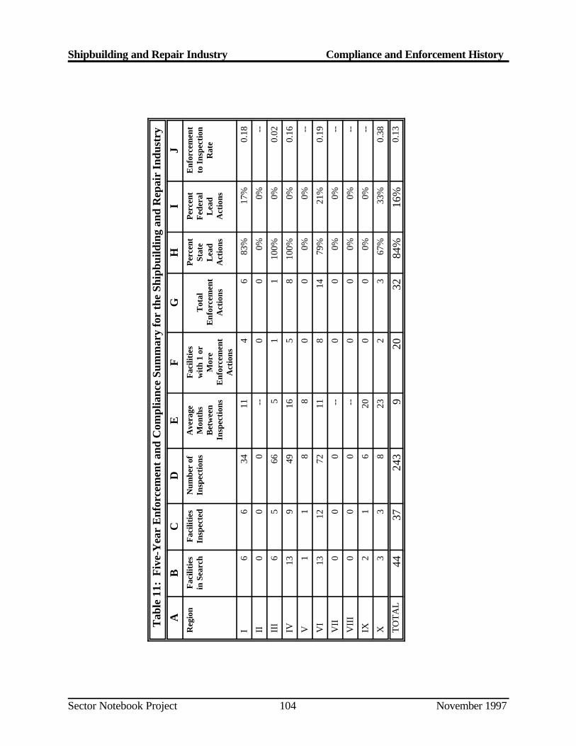
Shipbuilding and Repair Industry Compliance and Enforcement History
Sector Notebook Project November 1997104
Tab
le 1
1: F
ive-
Yea
r E
nfor
cem
ent a
nd C
ompl
ianc
e Su
mm
ary
for
the
Ship
build
ing
and
Rep
air
Indu
stry
AB
CD
EF
GH
IJ
Reg
ion
Fac
iliti
esin
Sea
rch
Fac
iliti
esIn
spec
ted
Num
ber
ofIn
spec
tion
sA
vera
geM
onth
sB
etw
een
Insp
ecti
ons
Fac
iliti
esw
ith
1 or
Mor
eE
nfor
cem
ent
Act
ions
Tot
alE
nfor
cem
ent
Act
ions
Per
cent
Stat
eL
ead
Act
ions
Per
cent
Fed
eral
Lea
dA
ctio
ns
Enf
orce
men
tto
Ins
pect
ion
Rat
e
I6
634
114
683
%17
%0.
18
II0
00
--0
00%
0%--
III
65
665
11
100%
0%0.
02
IV13
949
165
810
0%0%
0.16
V1
18
80
00%
0%--
VI
1312
7211
814
79%
21%
0.19
VII
00
0--
00
0%0%
--
VII
I0
00
--0
00%
0%--
IX2
16
200
00%
0%--
X3
38
232
367
%33
%0.
38
TO
TA
L44
3724
39
2032
84%
16%
0.13
Shipbuilding and Repair Industry Compliance and Enforcement History
Sector Notebook Project November 1997105
VII.B. Comparison of Enforcement and Compliance Activity Between Selected Industries
Tables 12 and 13 allow the compliance history of the shipbuilding and repairsector to be compared to the other industries covered by the industry sectornotebook project. Comparisons between Tables 12 and 13 permit th eidentification of trends in compliance an d enforcement records of the industryby comparing data covering the last five years (April 1992 to April 1997) tothat of the past year (April 1996 to April 1997). Some points evident fromthe data are listed below.
Of the sectors shown, the shipbuil ding and repair industry had, by far,the smallest number of facilities (44) in the database search. (Th efacilities presented only include those facilities that report to TRI.)
The shipbuilding and repair industry had one of the highes tenforcement to inspection rates over the past five years (0.13) .However, this rate decreased significantly over the past year (0.08).
Compared to the other sectors shown, the i ndustry was about averagein terms of the percent of facilities with violations (86 percent) an denforcement actions (14 percent) in the past year, and in the averagetime between inspections over the past five years (9 months).
Tables 14 and 15 provide a more in-depth comparison between th eshipbuilding and repair industry and other sectors by breaking out th ecompliance and enforcement data by environmental statute. As in th eprevious Tables (Tables 12 and 13), the data cover the last five years (Table14) and the last one year (Table 15) to facilitate the identification of recen ttrends. A few points evident from the data are listed below.
Inspections carried out under CAA and RCRA accounted for 8 1percent and 89 percent of inspectio ns over the past five years and oneyear, respectively. RCRA inspections made up only 14 percent o finspections in the past five years, but accounted for 25 percent o fenforcement actions.
Over the past year, a larger percentage of inspe ctions were carried outunder CAA (54 percent) compared to the pas t five years (39 percent).
Meaningful comparisons of enforcement actions taken under eac hstatute over the past year are not possibl e since only four enforcementactions (two under RCRA and two under CWA) were taken in thi speriod.
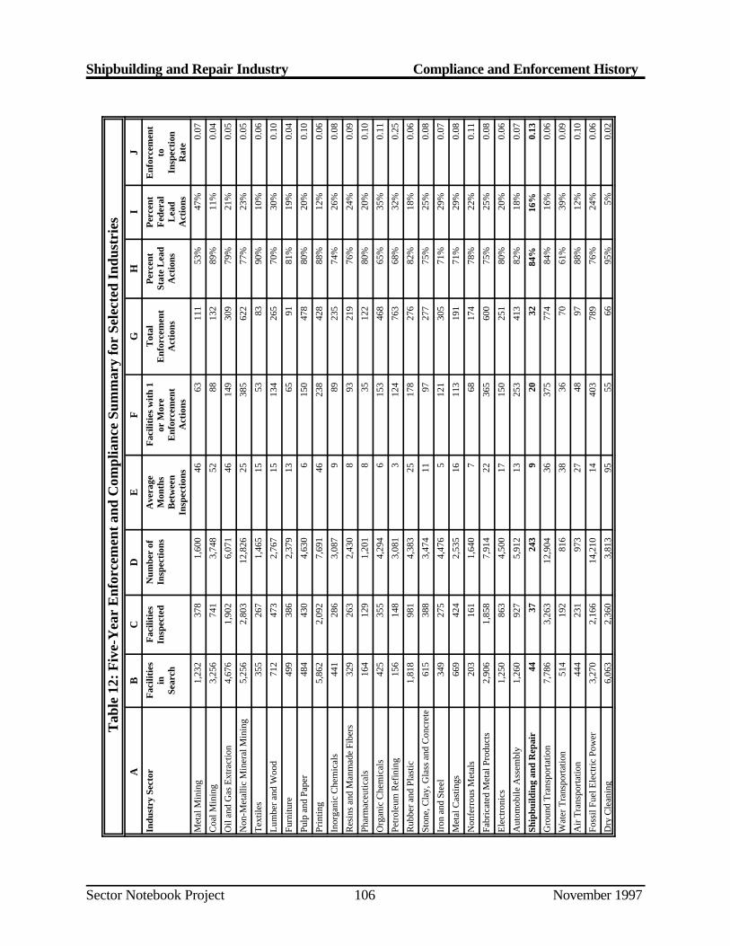
Shipbuilding and Repair Industry Compliance and Enforcement History
Sector Notebook Project November 1997106
Tab
le 1
2: F
ive-
Yea
r E
nfor
cem
ent a
nd C
ompl
ianc
e Su
mm
ary
for
Sele
cted
Ind
ustr
ies
AB
CD
EF
GH
IJ
Indu
stry
Sec
tor
Fac
iliti
esin
Sear
ch
Fac
iliti
esIn
spec
ted
Num
ber
ofIn
spec
tion
sA
vera
geM
onth
sB
etw
een
Insp
ecti
ons
Fac
iliti
es w
ith
1or
Mor
eE
nfor
cem
ent
Act
ions
Tot
alE
nfor
cem
ent
Act
ions
Per
cent
Stat
e L
ead
Act
ions
Per
cent
Fed
eral
Lea
dA
ctio
ns
Enf
orce
men
tto
Insp
ecti
onR
ate
Met
al M
inin
g1,
232
378
1,60
046
6311
153
%47
%0.
07
Coa
l Min
ing
3,25
674
13,
748
5288
132
89%
11%
0.04
Oil
and
Gas
Ext
ract
ion
4,67
61,
902
6,07
146
149
309
79%
21%
0.05
Non
-Met
allic
Min
eral
Min
ing
5,25
62,
803
12,8
2625
385
622
77%
23%
0.05
Tex
tiles
355
267
1,46
515
5383
90%
10%
0.06
Lum
ber a
nd W
ood
712
473
2,76
715
134
265
70%
30%
0.10
Furn
iture
499
386
2,37
913
6591
81%
19%
0.04
Pulp
and
Pap
er48
443
04,
630
615
047
880
%20
%0.
10
Prin
ting
5,86
22,
092
7,69
146
238
428
88%
12%
0.06
Inor
gani
c C
hem
ical
s44
128
63,
087
989
235
74%
26%
0.08
Res
ins
and
Man
mad
e Fi
bers
329
263
2,43
08
9321
976
%24
%0.
09
Phar
mac
eutic
als
164
129
1,20
18
3512
280
%20
%0.
10
Org
anic
Che
mic
als
425
355
4,29
46
153
468
65%
35%
0.11
Petr
oleu
m R
efin
ing
156
148
3,08
13
124
763
68%
32%
0.25
Rub
ber a
nd P
last
ic1,
818
981
4,38
325
178
276
82%
18%
0.06
Ston
e, C
lay,
Gla
ss a
nd C
oncr
ete
615
388
3,47
411
9727
775
%25
%0.
08
Iron
and
Ste
el34
927
54,
476
512
130
571
%29
%0.
07
Met
al C
astin
gs66
942
42,
535
1611
319
171
%29
%0.
08
Non
ferr
ous
Met
als
203
161
1,64
07
6817
478
%22
%0.
11
Fabr
icat
ed M
etal
Pro
duct
s2,
906
1,85
87,
914
2236
560
075
%25
%0.
08
Ele
ctro
nics
1,25
086
34,
500
1715
025
180
%20
%0.
06
Aut
omob
ile A
ssem
bly
1,26
092
75,
912
1325
341
382
%18
%0.
07
Ship
build
ing
and
Rep
air
4437
243
920
3284
%16
%0.
13
Gro
und
Tra
nspo
rtat
ion
7,78
63,
263
12,9
0436
375
774
84%
16%
0.06
Wat
er T
rans
port
atio
n51
419
281
638
3670
61%
39%
0.09
Air
Tra
nspo
rtat
ion
444
231
973
2748
9788
%12
%0.
10
Foss
il Fu
el E
lect
ric
Pow
er3,
270
2,16
614
,210
1440
378
976
%24
%0.
06
Dry
Cle
anin
g6,
063
2,36
03,
813
9555
6695
%5%
0.02
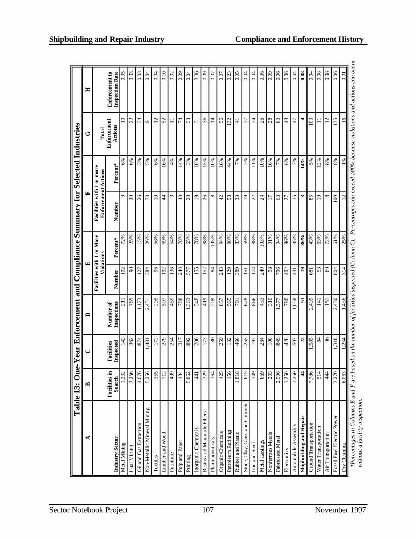
Shipbuilding and Repair Industry Compliance and Enforcement History
Sector Notebook Project November 1997107
Tab
le 1
3: O
ne-Y
ear
Enf
orce
men
t and
Com
plia
nce
Sum
mar
y fo
r Se
lect
ed I
ndus
trie
sA
BC
DE
FG
HF
acili
ties
wit
h 1
or M
ore
Vio
lati
ons
Fac
iliti
es w
ith
1 or
mor
eE
nfor
cem
ent A
ctio
nsT
otal
Enf
orce
men
tA
ctio
nsIn
dust
ry S
ecto
rF
acili
ties
inSe
arch
Fac
iliti
esIn
spec
ted
Num
ber
ofIn
spec
tion
sN
umbe
rP
erce
nt*
Num
ber
Per
cent
*E
nfor
cem
ent t
oIn
spec
tion
Rat
eM
etal
Min
ing
1,23
214
221
110
272
%9
6%10
0.05
Coa
l Min
ing
3,25
636
276
590
25%
206%
220.
03O
il an
d G
as E
xtra
ctio
n4,
676
874
1,17
312
715
%26
3%34
0.03
Non
-Met
allic
Min
eral
Min
ing
5,25
61,
481
2,45
138
426
%73
5%91
0.04
Tex
tiles
355
172
295
9656
%10
6%12
0.04
Lum
ber a
nd W
ood
712
279
507
192
69%
4416
%52
0.10
Furn
iture
499
254
459
136
54%
94%
110.
02Pu
lp a
nd P
aper
484
317
788
248
78%
4314
%74
0.09
Prin
ting
5,86
289
21,
363
577
65%
283%
530.
04In
orga
nic
Che
mic
als
441
200
548
155
78%
1910
%31
0.06
Res
ins
and
Man
mad
e Fi
bers
329
173
419
152
88%
2615
%36
0.09
Phar
mac
eutic
als
164
8020
984
105%
810
%14
0.07
Org
anic
Che
mic
als
425
259
837
243
94%
4216
%56
0.07
Petr
oleu
m R
efin
ing
156
132
565
129
98%
5844
%13
20.
23R
ubbe
r and
Pla
stic
1,81
846
679
138
983
%33
7%41
0.05
Ston
e, C
lay,
Gla
ss a
nd C
oncr
ete
615
255
678
151
59%
197%
270.
04Ir
on a
nd S
teel
349
197
866
174
88%
2211
%34
0.04
Met
al C
astin
gs66
923
443
324
010
3%24
10%
260.
06N
onfe
rrou
s M
etal
s20
310
831
098
91%
1716
%28
0.09
Fabr
icat
ed M
etal
2,90
684
91,
377
796
94%
637%
830.
06E
lect
roni
cs1,
250
420
780
402
96%
276%
430.
06A
utom
obile
Ass
embl
y1,
260
507
1,05
843
185
%35
7%47
0.04
Ship
build
ing
and
Rep
air
4422
5119
86%
314
%4
0.08
Gro
und
Tra
nspo
rtat
ion
7,78
61,
585
2,49
968
143
%85
5%10
30.
04W
ater
Tra
nspo
rtat
ion
514
8414
153
63%
1012
%11
0.08
Air
Tra
nspo
rtat
ion
444
9615
169
72%
88%
120.
08Fo
ssil
Fuel
Ele
ctri
c Po
wer
3,27
01,
318
2,43
080
461
%10
08%
135
0.06
Dry
Cle
anin
g6,
063
1,23
41,
436
314
25%
121%
160.
01
*Per
cent
ages
in C
olum
ns E
and
F a
re b
ased
on
the
num
ber o
f fac
ilitie
s ins
pect
ed (C
olum
n C
). P
erce
ntag
es c
an e
xcee
d 10
0% b
ecau
se v
iola
tions
and
act
ions
can
occ
urw
ithou
t a fa
cilit
y in
spec
tion.
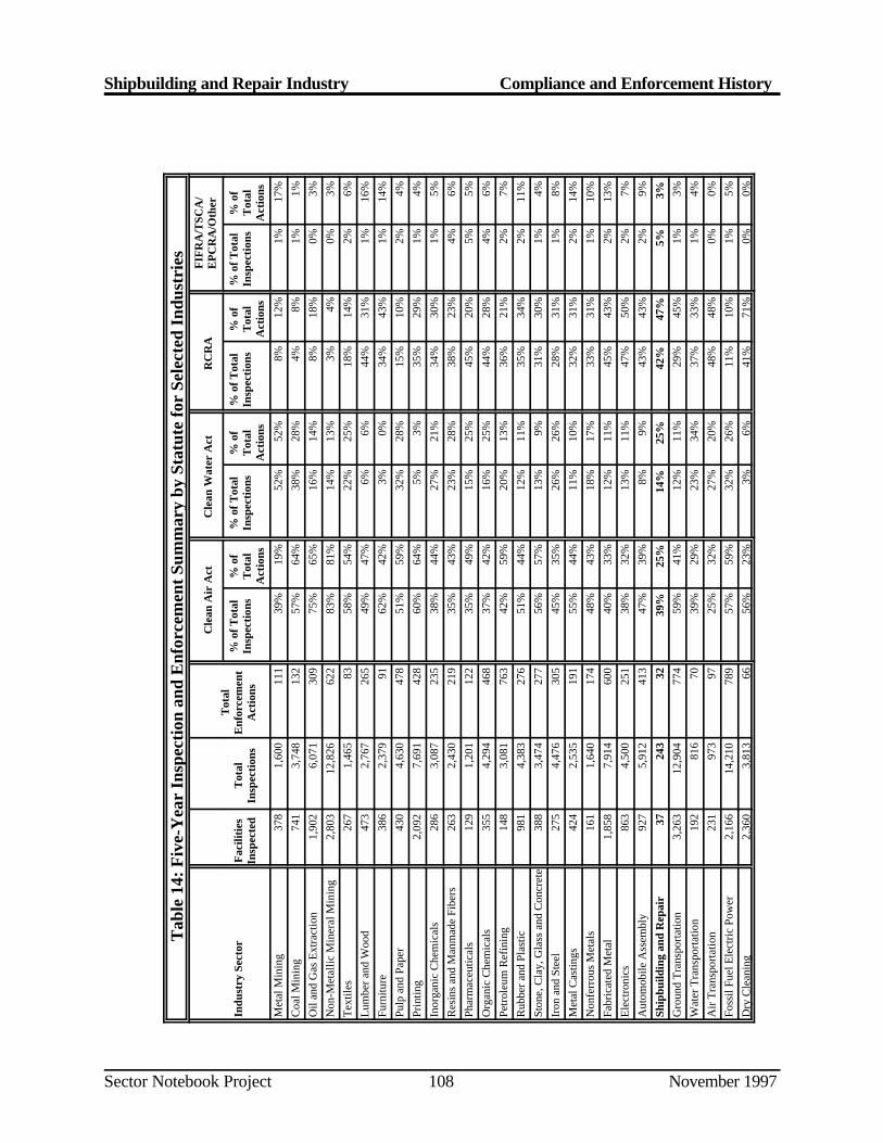
Shipbuilding and Repair Industry Compliance and Enforcement History
Sector Notebook Project November 1997108
Tab
le 1
4: F
ive-
Yea
r In
spec
tion
and
Enf
orce
men
t Sum
mar
y by
Sta
tute
for
Sele
cted
Ind
ustr
ies
Indu
stry
Sec
tor
Fac
iliti
esIn
spec
ted
Tot
alIn
spec
tion
s
Tot
alE
nfor
cem
ent
Act
ions
Cle
an A
ir A
ctC
lean
Wat
er A
ctR
CR
AF
IFR
A/T
SCA
/E
PC
RA
/Oth
er
% o
f Tot
alIn
spec
tion
s%
of
Tot
alA
ctio
ns
% o
f Tot
alIn
spec
tion
s%
of
Tot
alA
ctio
ns
% o
f Tot
alIn
spec
tion
s%
of
Tot
alA
ctio
ns
% o
f Tot
alIn
spec
tion
s%
of
Tot
alA
ctio
ns
Met
al M
inin
g37
81,
600
111
39%
19%
52%
52%
8%12
%1%
17%
Coa
l Min
ing
741
3,74
813
257
%64
%38
%28
%4%
8%1%
1%O
il an
d G
as E
xtra
ctio
n1,
902
6,07
130
975
%65
%16
%14
%8%
18%
0%3%
Non
-Met
allic
Min
eral
Min
ing
2,80
312
,826
622
83%
81%
14%
13%
3%4%
0%3%
Tex
tiles
267
1,46
583
58%
54%
22%
25%
18%
14%
2%6%
Lum
ber a
nd W
ood
473
2,76
726
549
%47
%6%
6%44
%31
%1%
16%
Furn
iture
386
2,37
991
62%
42%
3%0%
34%
43%
1%14
%Pu
lp a
nd P
aper
430
4,63
047
851
%59
%32
%28
%15
%10
%2%
4%Pr
intin
g2,
092
7,69
142
860
%64
%5%
3%35
%29
%1%
4%In
orga
nic
Che
mic
als
286
3,08
723
538
%44
%27
%21
%34
%30
%1%
5%R
esin
s an
d M
anm
ade
Fibe
rs26
32,
430
219
35%
43%
23%
28%
38%
23%
4%6%
Phar
mac
eutic
als
129
1,20
112
235
%49
%15
%25
%45
%20
%5%
5%O
rgan
ic C
hem
ical
s35
54,
294
468
37%
42%
16%
25%
44%
28%
4%6%
Petr
oleu
m R
efin
ing
148
3,08
176
342
%59
%20
%13
%36
%21
%2%
7%R
ubbe
r and
Pla
stic
981
4,38
327
651
%44
%12
%11
%35
%34
%2%
11%
Ston
e, C
lay,
Gla
ss a
nd C
oncr
ete
388
3,47
427
756
%57
%13
%9%
31%
30%
1%4%
Iron
and
Ste
el27
54,
476
305
45%
35%
26%
26%
28%
31%
1%8%
Met
al C
astin
gs42
42,
535
191
55%
44%
11%
10%
32%
31%
2%14
%N
onfe
rrou
s M
etal
s16
11,
640
174
48%
43%
18%
17%
33%
31%
1%10
%Fa
bric
ated
Met
al1,
858
7,91
460
040
%33
%12
%11
%45
%43
%2%
13%
Ele
ctro
nics
863
4,50
025
138
%32
%13
%11
%47
%50
%2%
7%A
utom
obile
Ass
embl
y92
75,
912
413
47%
39%
8%9%
43%
43%
2%9%
Ship
build
ing
and
Rep
air
3724
332
39%
25%
14%
25%
42%
47%
5%3%
Gro
und
Tra
nspo
rtat
ion
3,26
312
,904
774
59%
41%
12%
11%
29%
45%
1%3%
Wat
er T
rans
port
atio
n19
281
670
39%
29%
23%
34%
37%
33%
1%4%
Air
Tra
nspo
rtat
ion
231
973
9725
%32
%27
%20
%48
%48
%0%
0%Fo
ssil
Fuel
Ele
ctri
c Po
wer
2,16
614
,210
789
57%
59%
32%
26%
11%
10%
1%5%
Dry
Cle
anin
g2,
360
3,81
366
56%
23%
3%6%
41%
71%
0%0%
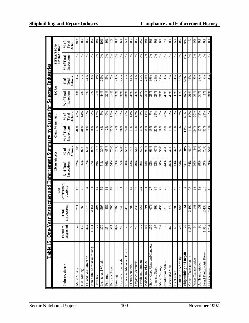
Shipbuilding and Repair Industry Compliance and Enforcement History
Sector Notebook Project November 1997109
Tab
le 1
5: O
ne-Y
ear
Insp
ecti
on a
nd E
nfor
cem
ent S
umm
ary
by S
tatu
te fo
r Se
lect
ed I
ndus
trie
s
Fac
iliti
esIn
spec
ted
Tot
alIn
spec
tion
s
Tot
alE
nfor
cem
ent
Act
ions
Cle
an A
ir A
ctC
lean
Wat
er A
ctR
CR
AF
IFR
A/T
SCA
/E
PC
RA
/Oth
er
Indu
stry
Sec
tor
% o
f Tot
alIn
spec
tion
s%
of
Tot
alA
ctio
ns
% o
f Tot
alIn
spec
tion
s%
of
Tot
alA
ctio
ns
% o
f Tot
alIn
spec
tion
s%
of
Tot
alA
ctio
ns
% o
f Tot
alIn
spec
tion
s%
of
Tot
alA
ctio
ns
Met
al M
inin
g14
221
110
52%
0%40
%40
%8%
30%
0%30
%C
oal M
inin
g36
276
522
56%
82%
40%
14%
4%5%
0%0%
Oil
and
Gas
Ext
ract
ion
874
1,17
334
82%
68%
10%
9%9%
24%
0%0%
Non
-Met
allic
Min
eral
Min
ing
1,48
12,
451
9187
%89
%10
%9%
3%2%
0%0%
Tex
tiles
172
295
1266
%75
%17
%17
%17
%8%
0%0%
Lum
ber a
nd W
ood
279
507
5251
%30
%6%
5%44
%25
%0%
40%
Furn
iture
254
459
1166
%45
%2%
0%32
%45
%0%
9%Pu
lp a
nd P
aper
317
788
7454
%73
%32
%19
%14
%7%
0%1%
Prin
ting
892
1,36
353
63%
77%
4%0%
33%
23%
0%0%
Inor
gani
c C
hem
ical
s20
054
831
35%
59%
26%
9%39
%25
%0%
6%R
esin
s an
d M
anm
ade
Fibe
rs17
341
936
38%
51%
24%
38%
38%
5%0%
5%Ph
arm
aceu
tical
s80
209
1443
%71
%11
%14
%45
%14
%0%
0%O
rgan
ic C
hem
ical
s25
983
756
40%
54%
13%
13%
47%
34%
0%0%
Petr
oleu
m R
efin
ing
132
565
132
49%
67%
17%
8%34
%15
%0%
10%
Rub
ber a
nd P
last
ic46
679
141
55%
64%
10%
13%
35%
23%
0%0%
Ston
e, C
lay,
Gla
ss a
nd C
oncr
ete
255
678
2762
%63
%10
%7%
28%
30%
0%0%
Iron
and
Ste
el19
786
634
52%
47%
23%
29%
26%
24%
0%0%
Met
al C
astin
gs23
443
326
60%
58%
10%
8%30
%35
%0%
0%N
onfe
rrou
s M
etal
s10
831
028
44%
43%
15%
20%
41%
30%
0%7%
Fabr
icat
ed M
etal
849
1,37
783
46%
41%
11%
2%43
%57
%0%
0%E
lect
roni
cs42
078
043
44%
37%
14%
5%43
%53
%0%
5%A
utom
obile
Ass
embl
y50
71,
058
4753
%47
%7%
6%41
%47
%0%
0%
Ship
build
ing
and
Rep
air
2251
454
%0%
11%
50%
35%
50%
0%0%
Gro
und
Tra
nspo
rtat
ion
1,58
52,
499
103
64%
46%
11%
10%
26%
44%
0%1%
Wat
er T
rans
port
atio
n84
141
1138
%9%
24%
36%
38%
45%
0%9%
Air
Tra
nspo
rtat
ion
9615
112
28%
33%
15%
42%
57%
25%
0%0%
Foss
il Fu
el E
lect
ric
Pow
er1,
318
2,43
013
559
%73
%32
%21
%9%
5%0%
0%D
ry C
lean
ing
1,23
41,
436
1669
%56
%1%
6%30
%38
%0%
0%
Shipbuilding and Repair Industry Compliance and Enforcement History
Sector Notebook Project November 1997110
VII.C. Review of Major Legal Actions
Major Cases/Supplemental Environmental Projects
This section provides summary information about major cases that hav eaffected this sector, and a list of Supplemental Environmental Project s(SEPs).
VII.C.1. Review of Major Cases
As indicated in EPA’s Enforcement Accomplishments Report, FY1995 an dFY1996 publications, two significant enforcement actions were resolve dbetween 1995 and 1996 for the shipbuilding industry.
U.S. v. First Marine Shipyard Inc., et al. (E.D.NY): On September 30, 1996the U.S. filed a complaint for CERCLA cost recovery and penalties relate dto Region II’s cleanup of the barge Nathan Berman . The complaint seek srecovery of approximately $1,8 million from First Marine Shipyard, MarineFacilities Inc., Marine Movements, Inc., and Peter Frank and Jane Fran kKresch individually. It also includes a second cause of action against Firs tMarine Shipyard for failu re to comply with an administrative CERCLA §106order issued to it in March of 1993.
Cascade General: Cascade General, a ship repair fac ility in Portland, Oregon,agreed to a penalty o f $78,568 for alleged EPCRA violations. The companyagreed to pay $39,284 in cash and install air filtration dust collector an dsolvent recovery systems and to switch to water-based paint to remediate thebalance of the penalty. The SEPs will cost about $1 17,000 to implement. Thedust collector will imp rove air quality in the facility by reducing dust in workareas. The solvent recovery system will reduce by 90% the amount of solventsdischarged to the air by recovering batch solvents fo r reuse in the facility. ForTRI reporting years 1988-1993, total releases were reported at 253,00 0pounds.
VII.C.2. Supplementary Environmental Projects (SEPs)
Supplemental environmental projects (SEPs) are enforcement options tha trequire the non-compliant facility to complete specific projects. Informationon SEP cases can be accessed via the in ternet at EPA’s Enviro$en$e website:http://es.inel.gov/sep.
Shipbuilding and Repair Activities and Initiatives
Sector Notebook Project November 1997111
VIII. COMPLIANCE ASSURANCE ACTIVITIES AND INITIATIVES
This section highlights the activities undertaken by this industry sector an dpublic agencies to voluntarily improve the sector's environmenta lperformance. These activities include those independently initiated b yindustrial trade associations. In this section, the notebook also contains alisting and description of national and regional trade associations.
VIII.A. Sector-related Environmental Programs and Activities
National Shipbuilding Research Program Panel SP-1
The National Shipbuilding Research Program (NSRP) is a join tindustry/government program aimed at improving the global competitivenessof American shipyards. NSRP ’s mission is to assist the shipbuilding and shiprepair industry in achieving and maintaining global competitiveness wit hrespect to quality, time, cos t, and customer satisfaction. The program is alsoexpected to significant ly reduce the costs and delivery times of ships orderedby the U.S. Navy. NSRP’s objectives are r eached through individual projectswhich form the content of the shipbuilding technology program. Join tGovernment and industry meetings are held to identify final projec tdescriptions. NSRP utilizes a panel structure to develop project proposal sand implement projects. The Panel SP-1 focuses on shipbuilding and repairfacilities and environmental effects.
The mission of Panel SP-1, Facilities and En vironmental Effects, is to supportthe NSRP by providing leadership and expertis e to the shipbuilding and repairindustry, with respect to facilities and environmental issues. The followin ggoals have been established by SP-1:
increase participation of shipyards and other Maritime Association sby 100 percent;
improve communication and visibility b etween NSRP Panels, with theExecutive Control Board, within NSRP participating shipyards an dbeyond NSRP;
be proactive in representing industry views regarding regulator ymatters;
identify, develop and implement cost-effective technologies i nfacilities and environmental areas;
educate and assist the shipbuilding and repair industry and it scustomers in meeting environmental a nd regulatory requirements; and
Shipbuilding and Repair Activities and Initiatives
Sector Notebook Project November 1997112
maintain and continue to improve SP-1 expertise.
Panel SP-1 has a number of active and proposed projects. The following isa list of active projects:
Environmental Studies and Testing
Environmental Training Modules
Feasibility and Economic Study of the Treatment, Recycling &Disposal of Spent Abrasives
Solid Waste Segregation & Recycling
Title V Permit for Shipyards Strategy Guide for Development o fGenerated Permit
Wastewater Treatment Technology Survey
Impact on Shipyards from the Reauthorization of the Federal Clea nWater Act
Development of Guidance for Selecting Legitimate Recyclin gProducts and Processes
Developing a Shipyard Program for NPDES Compliance
More information on Panel SP-1 activities can be obtained from th eEnvironmental Resources and Information Center (ERIC), a division of theGulf Coast Region Maritime Technology Center at the University of Ne wOrleans at (504) 286-6053.
National Defense Center for Environmental Excellence
The National Defense Center for Environmental Excellence (NDCEE) wa sestablished by th e Department of Defense to provide the military and privatesector industrial base clients with environmentally compliant technologies .NDCEE conducts environmental technology research and disseminate sinformation on environmental technologies and regulations. At the Army’sArmament Research, Development and Engineering Center at Picatinn yArsenal, NJ, NDCEE has established an industrial-scale facility for th edemonstration of nonpolluting surface coatings. The NDCEE demonstrationfacility is used to validate cost, schedul es and performance parameters of newcoating technologies. NDCEE also provides assistance in the form o fequipment, site engineers, economic analyses, training, and troubleshootingfor those clients implementing demonstrated coating technologies at thei r
Shipbuilding and Repair Activities and Initiatives
Sector Notebook Project November 1997113
industrial facility. In its powder coating demonstration line, industrial partsare cleaned, pretreated, sprayed with nonpolluting organic powders, the ncured in a process than nearly eliminates volatile organic compounds an dhazardous wastes. Contact: Dr. Dale A. Denny , Executive Director, NDCEE,(814) 269-2432.
MARITECH
MARITECH is a five-year jointly funded by the Federal Government an dindustry and is administered by the Department of Defense’s Advance dResearch Projects Agency (ARPA), in collaboration with MARAD .MARITECH provides matching Government funds to encourage th eshipbuilding industry to direct and lead in the development and application ofadvanced technology to improve its competitiveness and to preserve it sindustrial base. In the near-term MARITECH aims to assist industry i npenetrating the international marketplace with competitive ship designs ,market strategies, and modern shipbuilding processes and procedures. In thelong-term, the program is meant to encourage advanced ship and shipbuildingtechnology projects for promoting continuous product and proces simprovement in order to maintain and enlarge the U.S. share of th ecommercial and international market. MARITECH funded $30 million i nFY94, $40 million in FY95, $50 million in F Y96, and $50 million in FY97 forvessel design and shipyard technology projects.
Shipbuilding and Repair Activities and Initiatives
Sector Notebook Project November 1997114
VIII.B. EPA Voluntary Programs
33/50 Program
The "33/50 Program" is EPA's voluntary program to reduce toxic chemicalreleases and transfers of seventeen chemicals from manufacturing facilities .Participating companies pledge to reduce their toxic chemical releases an dtransfers by 33% as of 1992 and by 50% as of 1995 from the 1988 baselineyear. Certificates of Appreciation have been given out to participants meetingtheir 1992 goals. The list of chemi cals includes seventeen high-use chemicalsreported in the Toxics Release Inventory. Table 16 lists those companie sparticipating in the 33/50 program that re ported the four-digit SIC code 3731to TRI. Som e of the companies shown also listed facilities that are no tbuilding or repairing ships. The number of fac ilities within each company thatare participating in the 33/50 program and that report the shipbuilding an drepair SIC code is shown. Where available and quantifiable against 198 8releases and transfers, each company’s 33/50 goals for 1995 and the actua ltotal releases and transfers and pe rcent reduction between 1988 and 1994 arepresented. TRI 33/50 data for 1995 was not available at the time o fpublication.
Twelve of the seventeen target chemicals were reported to TRI b yshipbuilding and repair facilities in 1994. Of all TRI chemicals released an dtransferred by the shipbuilding and repair industry, xylenes (a 33/50 targe tchemical), was released and transferred most frequently (32 facilities), an dwas the top chemical by volume released and transferred. Toluene, the nextmost frequent ly reported 33/50 chemical, was reported by six facilities. Theremaining 33/50 chemicals were each reported by four or fewer facilities.
Table 16 shows that 7 companies comprised of 15 facilities reporting SI C3731 are participating in the 33/50 program. For those companies show nwith more than one sh ipyard, all shipyards may not be participating in 33/50.The 33/50 goal s shown for companies with multiple shipyards are company-wide, potentially aggregating more than one shipyard and facilities no tcarrying out shipbuilding and repair oper ations. In addition to company-widegoals, individual facilities within a company may have their own 33/50 goalsor may be specificall y listed as not participating in the 33/50 program. Sincethe actual percent reductions shown in the last column apply to all of th ecompanies’ shi pbuilding and repair facilities and only shipbuilding and repairfacilities, direct comparisons to those company goals incorporating non -shipbuilding and repair facilities or excluding certain facilities may not b epossible. For informati on on specific facilities participating in 33/50, contactDavid Sarokin (202-260-6907) at the 33/50 Program Office.
Shipbuilding and Repair Activities and Initiatives
Sector Notebook Project November 1997115
Table 16: Shipbuilding and Repair Industry Participation in the 33/50 Program
Parent Company (Headquarters Location)
Company- Company- 1988 TRI 1994 TRI Actual %Owned Wide % Releases and Releases and Reduction for
Shipyards Reduction Transfers of Transfers of ShipyardsReporting 33/50 Goal 33/50 Chemicals 33/50 Chemicals (1988-1994)
Chemicals (1988 to 1995) (pounds) (pounds)
1
Avondale Industries Inc.Avondale, LA
3 54 1,558,614 20,285 99
Bethlehem Steel Corp.Bethlehem, PA
2 50 92,000 129,020 -40
Fulcrum II Limited Partner.(Bath Iron Works)New York, NY
4 24 116,500 15,331 87
General Dynamics Corp.Falls Church, VA
2 84 316,777 8,182 97
Tenneco Inc.(Newport News)Houston, TX
1 8 896,292 268,950 70
U.S. Air ForceWashington, DC
1 *** 0 108,835 -
Unimar International Inc.Seattle, WA
1 * 0 0 -
TOTAL 15 -- 2,980,183 550,603 86Source: U.S. EPA 33/50 Program Office, 1996.
Company-Wide Reduction Goals aggregate all company-owned facilities which may include1
facilities not building and repairing ships.
* = Reduction goal not quantifiable against 1988 TRI data.** = Use reduction goal only.*** = No numeric reduction goal.
Shipbuilding and Repair Activities and Initiatives
Sector Notebook Project November 1997116
Environmental Leadership Program
The Environmental Leadership Program (ELP) is a national initiativ edeveloped by EPA that focuses on improving environmental performance ,encouraging voluntary compliance, and building working relationships withstakeholders. EPA initiated a one year p ilot program in 1995 by selecting 12projects at industrial facilities and federal installations which woul ddemonstrate the principles of the ELP program. These principles include :environmental management systems, mul timedia compliance assurance, third-party verification o f compliance, public measures of accountability, pollutionprevention, community involvement, and mentor programs. In return fo rparticipating, pilot participants received public recognition and were given aperiod of time to correct an y violations discovered during these experimentalprojects.
EPA is making plans to launch its full-scale Environmental Leadershi pProgram in 1997. T he full-scale program will be facility-based with a 6-yearparticipation cycle. Facilities that meet certain requirements will be eligibleto participate, such as having a community outreach/employee involvementprograms and an environmental management system (EMS) in place for 2years. (Contact: http://es.inel.gov/elp or Debby Thomas, ELP Deput yDirector, at 202-564-5041)
Project XL
Project XL was initiated in March 1995 as a part of President Clinton’ sReinventing Environmental Regulation initiative. The projects seek t oachieve cost effective environmental benefits by providing participant sregulatory flexibility on the condition that th ey produce greater environmentalbenefits. EPA and program participants will negotiate a nd sign a Final ProjectAgreement, detailing specific environmental objectives that the regulate dentity shall satisfy. EPA will provide regulatory flexibility as an incentive forthe participants’ superior environmental performance. Participants ar eencouraged to seek sta keholder support from local governments, businesses,and environmental groups. EPA hopes to implement fifty pilot projects i nfour categories, including industrial facilities, communities, and governmentfacilities regulated by EPA. Applications will be accepted on a rolling basis.For additional information regarding XL projects, including applicatio nprocedure s and criteria, see the May 23, 1995 Federal Register Notice .(Contact: Fax-on-Demand Hotline 202-260-8590, Web :http://www.epa.gov/ProjectXL, or Christopher Knopes at EPA’s Office o fPolicy, Planning and Evaluation 202-260-9298)
Shipbuilding and Repair Activities and Initiatives
Sector Notebook Project November 1997117
Climate Wise Program
Climate Wise is helping US industries turn energy efficiency and pollutio nprevention into a corporate asset. Supported by the technical assistance ,financing information and public recognition that Climate Wise offers ,participating companies are developing and launching comprehensiv eindustrial energy efficiency and pollution prevention action plans that sav emoney and protect the environment. The nearl y 300 Climate Wise companiesexpect to save more than $300 million and reduce greenhouse gas emissionsby 18 million metric tons of carbon dioxide equivalent by the year 2000 .Some of the actions companies are undertaking to achieve these result sinclude: process improvements, boiler and steam system optimization, ai rcompressor system improvements, fuel switching, and waste heat recover ymeasures includin g cogeneration. Created as part of the President’s ClimateChange Action Plan, Climate Wise is jointly operated by the Department ofEnergy and EPA. Under the Plan many other programs were also launchedor upgraded including Green Lights, Waste Wi$e and DoE’s Motor ChallengeProgram. Climate Wise provides an umbrella for these programs whic hencourage company participation by providing information on the range o fpartnership opportunities available. (Contact: Pamela Herman, EPA, 202-260-4407 or Jan Vernet, DoE, 202-586-4755)
Energy Star Buildings Program
EPA’s ENERGY STAR Buildings Program is a v oluntary, profit-based programdesigned to improve the energy-efficiency in commercial and industria lbuildings. Expanding the successful Green Lights Program, ENERGY STARBuildings was launched in 1995. This program relies on a 5-stage strateg ydesigned to maximize energy savings thereby lower ing energy bills, improvingoccupant comfort, and preventing pollution -- all at the same time. I fimplemented in every commercial and i ndustrial building in the United States,ENERGY STAR Buildings could cut the nation’s energ y bill by up to $25 billionand prevent up to 35% of carbon dioxide emissions. (This is equivalent t otaking 60 million cars of the road). ENERGY STAR Buildings participant sinclude corporations; small and medium sized businesses; local, federal an dstate governments; non-profit groups; schools; universities; and health car efacilities. EPA provides technical and non-technical support includin gsoftware, workshops, manuals, communication tools, and an informatio nhotline. EPA’s Office of Air and Radiation manages the operation of th eENERGY STAR Buildings Program. (Contact: Green Ligh t/Energy Star Hotlineat 1-888-STAR-YES or Maria Tikoff Vargas, E PA Program Director at 202-233-9178 or visit the ENERGY STAR Buildings Program website a thttp://www.epa.gov/appdstar/buildings/)
Shipbuilding and Repair Activities and Initiatives
Sector Notebook Project November 1997118
Green Lights Program
EPA’s Green Lights program was initiated in 1991 and has the goal o fpreventing pollution by encouraging U.S. institutions to use energy-efficientlighting technologies. The program saves money for businesses an dorganizations and creates a cleaner environment by reducing pollutant sreleased into the atmosphere. The program has o ver 2,345 participants whichinclude major corporations, sm all and medium sized businesses, federal, stateand local governments, non-profit groups, schools, universities, and healt hcare facilities. Each participant is required to survey their facilities an dupgrade lighting wherever it is profitable. As of M arch 1997, participants hadlowered their ele ctric bills by $289 million annually. EPA provides technicalassistance to the participants through a decision support software package ,workshops and manuals, and an information h otline. EPA’s Office of Air andRadiation is responsible for operating the Green Lights Program. (Contact:Green Light/Energy Star Hotline at 1-888-STARYES or Maria Tikof fVargar, EPA Program Director, at 202-233-9178 the )
WasteWi$e Program
The WasteWi$e Program was started in 1994 by EPA’s Office of Solid Wasteand Emergency Response. The pro gram is aimed at reducing municipal solidwastes by promoting waste prevention, recycling collection and th emanufacturing and purchase of recycled products. As of 1997, the programhad about 500 companies as members, one third of whom are Fortune 1000corporations. Members agree to identify and implement actions to reduc etheir solid wastes setting waste reduction goals and providing EPA wit hyearly progress reports. To member companies, EPA, in turn, provide stechnical assistance, publicat ions, networking opportunities, and national andregional recognition. (Contact: WasteWi$e Hotline at 1-800-372-9473 o rJoanne Oxley, EPA Program Manager, 703-308-0199)
NICE3
The U.S. Depar tment of Energy is administering a grant program called TheNational Industrial Competitiveness through Energy, Environment, an dEconomics (NICE ). By providing grants of up to 45 percent of the tota l3
project cost, the program encourages industry to reduce industrial waste a tits source and become more energy-efficient and cost-competitive throug hwaste minimization efforts. Grants are used by industry to design, test, anddemonstrate new processes and/or equipment with the potential to reduc epollution and increase energy efficiency. The program is open to al lindustries; however, priority is given to proposals from participants in th eforest products, chemicals, petrole um refining, steel, aluminum, metal castingand glass manufacturing sectors. (Contact: http//www.oit.doe.gov/access /nice3, Chris Sifri, DOE, 303-275-4723 or Eric Hass, DOE, 303-275-4728.)
Shipbuilding and Repair Activities and Initiatives
Sector Notebook Project November 1997119
Design for the Environment (DfE)
DfE is working with several industries to identify cost-effective pollutio nprevention strategies t hat reduce risks to workers and the environment. DfEhelps businesses compare and evaluate the performance, cost, pollutio nprevention benefits, and human health and environmenta l risks associated withexisting and alternative technologies. The goal of these projects is t oencourage businesses to consider and use cleaner products, processes, an dtechnologies. For more information about the DfE Program, call (202) 260-1678. To obtain copies of DfE materials or for general information abou tDfE, contact EPA’s Pollution Preven tion Information Clearinghouse at (202)260-1023 or visit the DfE Website at http://es.inel.gov/dfe.
Shipbuilding and Repair Activities and Initiatives
Sector Notebook Project November 1997120
VIII.C. Trade Associations
American Shipbuilding Association Members: 6600 Pennsylvania Ave. Suite 305 Contact: Frank LoseyWashington, DC 20003 (202)-544-9614Phone: (202)-544-8170 Fax: (202)-544-9618
The American Shipbuilding Association (ASA) is a private, non-profit trad eassociation comprising America ’s six largest private sector shipyards. The shipyardsare: Avondale Industries, Bath Iron Works, Electric Boat, Ingalls Shipbuilding ,National Steel & Shipbuilding Company, and Newpo rt News Shipbuilding. These sixshipyards employ the large majority of shipbu ilding employees in the U.S. More than98 percent of the Navy’s shipbuilding budget is spent on ships constructed in ASAshipyards. The goals of ASA are to preserve and promote the U.S. naval shipbuildingindustrial base as well as to educate the U.S. public and government to th eimportance of shipbuilding to the country. ASA publishes American Shipbuilde rNewsletter monthly.
National Shipyard Association Members: 44 companies1600 Wilson Blvd. Staff: 6Arlington, VA 22209Phone: (703) 351-6734Fax: (703) 351-6736
The National Shipyard Association (NSA) is a national trade association representingthe commercial shipbuilding, repair, and cleaning industry. NSA represents 4 4shipyard companies that own and operate over 90 shipyards in 17 states along th eGulf, Pacific, and Atlantic coasts of the U.S. NSA also has among its membership 16companies that supply services and products to the shipbuilding and repair industry.NSA aims to promote high standards of health, safety, and environmental awarenessthroughout the industry. NSA publishes a monthly newsletter, NSA Newsline .
Shipyard Association for Members: 67Environmental Responsibility Staff: 5Post Office Box 250 Contact: Scott TheriotLockport, LA 70374Phone: (504)-532-7272 Fax: (202)-532-7295
The Shipyard Association for Enviro nmental Responsibility (SAFER) was formed by67 shipbuilding and repair facilities in the states of Alabama, Louisiana, Mississippi,and Texas. The goal of SAFER is to work cooperatively with the federal and state
Shipbuilding and Repair Activities and Initiatives
Sector Notebook Project November 1997121
agencies to ensure that environmental standards truly reflect the environmenta lconcerns of the vastly different sizes and capabilities of the Gulf Coast shipyards.
Shipbuilders Council of America Members: 10901 No. Washington St. Suite 204 Staff: 10Arlington, VA 22314 Contact: Penny EastmanPhone: (703) 548-7447
The Shipbuilders Counci l of America (SCA) was founded in 1921 and is made up ofcompanies engaged in the construction and repair of vessels and other marine craft;manufacturers of all types of propelli ng machinery, boilers, marine auxiliaries, marineequipment and supplies; and drydock operat ors. SCA promotes and maintains soundprivate shipbuilding and ship repairing industries and adequate mobilization potentialof shipbuilding and repairing facilities, organizations, and skilled personnel in timesof national emergencies. A newsletter, Shipyard Chronicle , is published weekly.
Shipbuilding and Repair Activities and Initiatives
Sector Notebook Project November 1997122
Page 122 intentionally left blank.
Shipbuilding and Repair Industry Contacts and References
Many of the contacts listed above have provided valuable information and comments during the development of this5
document. EPA appreciates this support and acknowledges that the individuals listed do not necessarily endorse allstatements made within this notebook.
Sector Notebook Project November 1997123
IX. CONTACTS/ACKNOWLEDGMENTS/RESOURCE MATERIALSFor further information on selected topics within the shipbuilding and repair industry a list of contactsand publications are provided below.
Contacts 5
Name Organization Telephone Subject
Anthony Raia U.S. EPA - Office of Compliance (202) 564-6045 Multimedia Compliance
Mohamed Serageldin U.S. EPA - Office of Air Quality (919) 541-2379 Regulatory RequirementsPlanning and Standards (Air)
Steve Guile U.S. EPA - Office of Water (202) 260-9817 MP&M water regulations
Bhaskar Kura University of New Orleans (504) 280-6572 Multimedia pollutantoutputs and pollutionprevention
Section II: Introduction to the Shipbuilding and Repair Industry
U.S. Departme nt of Commerce, International Trade Administration, 1994 U.S. Industrial Outlook ,1995.
U.S. Department of Commerce, Bureau of the Census, 1992 Census of Manufacturers Industr ySeries: Ship and Boat Building, Railroad and Miscellaneous Transportation Equipment , 1996.
U.S. Department of Transportation, Maritime Administration , Outlook for the U.S. Shipbuilding andRepair Industry 1996 , April 1996.
U.S. Department of Transportation, Maritime Administration, Report on Survey of U.S. Shipbuildingand Repair Facilities 1995 , December 1995.
ICAF Publications, Shipbuilding Industry Study Report , 1996, http://198.80.36.91/ndu/ica f/isshp.html, March 1997.
OECD, Overview of the Ag reement Respecting Normal Competitive Conditions in the CommercialShipbuilding and Repair Industry, http://www.oecd.org/dsti/sid/wp7.html, March 1997.
National Shipbuilding Research Program , Panel SP-4), US Shipbuilding International Market Study1996-2005 , June 1995. SPFA:0001.
Shipbuilding and Repair Industry Contacts and References
Sector Notebook Project November 1997124
Section III: Industrial Process Description
Kura, Bhaskur (University of New Orleans) and Lacoste, Steve (Avondale Indu stries, Avondale, LA),Typical Waste Streams in a Shipbuilding Facility , 1996.
Storch, R.L., Hammon, C.P. , Bunch, H.M., & Moore, R.C., Ship Production , 2nd ed., The Societyof Naval Architects and Marine Engineers, Jersey City, New Jersey, 1995.
Thornton, James R., Ship and Boat Building and Repair, ILO Encyclopaedia of Occupationa lHealth and Safety 4th ed., International Labour Office, Geneva, Switzerland, 1996.
Development Document for the Proposed Effluent Limitations Guidelines and Standards for th eMetal Products and M achinery Phase 1 Point Source Category , 1995, U.S. EPA, Office of Water,(EPA-821-R-95-021).
Water Environment Federation, Pretreatment of Industrial Wastes, Manual of Practice No. FD-3 ,Alexandria, Virginia, 1994.
National Shipbuilding Research Program, Hazardous Waste Minimization Guide for Shipyards , U.S.Navy and National Steel and Shipbuilding Company (NASSCO), January 1994.
National Shipbuilding Research Program, Introduction to Production Processes and Facilities in theSteel Shipbuilding and Repair Industry , U.S. Navy and National Steel and Shipbuilding Company(NASSCO), February 1993.
Levy, Doug, Boat Paint Tied to Dolphin Deaths , USA Today, December 31, 1996.
Section IV: Chemical Release and Transfer Profile
1994 Toxics Release Inventory Public Data Release , U.S. EPA Office of Pollution Prevention andToxics, June 1996. (EPA 745-R-96-002)
Section V: Pollution Prevention Opportunities
National Shipbuilding Research Program, Hazardous Waste Minimization Guide for Shipyards , U.S.Navy and National Steel and Shipbuilding Company (NASSCO), January 1994.
Guides to Pollution Prevention, The Marine Maintenance and Repair Industry , U.S. EPA, Officeof Research and Development, Cincinnati, OH, October 1991. (EPA/625/7-91/015)
Development Document for the Proposed Effluent Limitations Guidelines and Standards for th eMetal Products and M achinery Phase 1 Point Source Category , 1995, U.S. EPA, Office of Water,(EPA-821-R-95-021).
Shipbuilding and Repair Industry Contacts and References
Sector Notebook Project November 1997125
Natan, Thomas E., Jr., Examples of Successful Pollution Prevention Programs , from IndustrialPollution Prevention Handbook , ed. Freeman, Harry M., McGraw-Hill, Inc., New York, 1995. pp.142-144.
Identification of Pollution for Possible Inclusion in Enforcement Agreements Using SupplementalEnvironmental Projects (SEPs) and Injunctive Relief, Final Report , March 1997. U.S. EPA, Officeof Enforcement and Compliance Assurance, (EPA-300-R-97-001).
Section VI: Summary of Applicable Federal Statutes and Regulations
Personal Correspondence with Mohamed Ser ageldin , U.S. EPA, Office of Air Quality Planning andStandards, Research Triangle Park, North Carolina, March 1997.
Personal Correspondence with Steve Guile, U.S. EPA, Office of Water, Engineering and AnalysisDivision, Washington, DC, April 1997.
Section VIII: Compliance Activities and Initiatives
National Shipbuilding Research Program, SNAME Panel SP-1 Newsletter , Volume 1, Number 1 ,Summer 1996.
Textile Industry Appendix
A-1
APPENDIX AINSTRUCTIONS FOR DOWNLOADING THIS NOTEBOOK
Electronic Access to this Notebook via the U.S. EPA Site on the World Wide Web (WWW)
This Notebook is available through the EPA Public Access Server and the Enviro$ens eCommunications Network on the World Wide Web at http://www.ep a.gov/oeca/sector/index.html . Enviro$ense is a free, public, environmental exchange system operated by EPA's Office o fEnforcement and Compliance Assurance and Office of Research and Development. The Networ kallows regulators, the regulated community, technical experts, and the general public to shar einformation regarding: pollution prevention and innovative technologies; environmental enforcementand compliance assistance; laws, executive orders, regulations, and policies; points of contact fo rservices and equipm ent; and other related topics. The Network welcomes receipt of environmentalmessages, information, and data from any public or private person or organization.
ACCESS THROUGH THE U.S.EPA WORLD WIDE WEB SITE
To access this Notebook through the Web, se t your web browser to the aforementioned webaddress, and select the desired Notebook; or point and click your way there as follows:
1) set your browser to our primary web address: http://www.epa.gov/oeca ;
2) select “Industry and Gov’t. Sectors”;
3) select “EPA Sector Notebooks”; and
4) select the desired sector and file format.
HELPLINE NUMBER FOR OECA’S WORLD WIDE WEB SITE : 703-908-2007
EPA OECA WORLD WIDE WEB MANAGER: Louis Paley 202-564-2613