sign legibility rules of thumb - american signssign legibility rules of thumb united states sign...
TRANSCRIPT
Sign Legibility Rules Of Thumb
UNITED STATES SIGN COUNCIL
2006 United States Sign Council
1
SIGN LEGIBILITY By Andrew Bertucci, United States Sign Council
Since 1996, the United States Sign Council (USSC) and its research arm, the United States Sign Council Foundation (USSCF) have funded an extensive array of studies into the legibility of on-premise signs and the manner in which motorists react to these signs in various roadside environments. Because of these ground breaking studies, it is now possible to determine, with a degree of certainty, the size of letters as well as the size of signs necessary to ensure motorist legibility. Most of this work has been synthesized in the current USSC publication entitled USSC Best Practices Standards for On-Premise Signs, which details methods for ascertaining sign size, legibility, and height for on-premise signs that are directly in view of a motorist approaching the sign. In addition, a study completed in 2006 and entitled On-Premise Signs, Determination of Parallel Sign Legibility and Letter Heights now provides similar methods for ascertaining legibility factors for signs not directly in view, such as wall mount building signs usually parallel to a motorist’s viewpoint.
The USSC Best Practices Standards and the parallel sign study offer relatively detailed analysis of the legibility factors involved with on-premise signs, and certainly should be utilized whenever such analysis is warranted. A number of equally useful generalizations, or time-saving rules-of-thumb based on the studies, however, can be applied to arrive at results which reflect legibility values which can be used as a general average applicable to most conditions. These are detailed below.
On Premise Sign Legibility Simplified Rules Of Thumb
How Motorists React To Signs In The Roadside Environment
Detecting and reading a roadside on-premise sign by a motorist involves a complex series of sequentially occurring events, both mental and physical. They include message detection and processing, intervals of eye and/or head movement alternating between the sign and the road environment, and finally, active maneuvering of the vehicle (such as lane changes, deceleration, and turning into a destination) as required in response to the stimulus provided by the sign.
Complicating this process is the dynamic of the viewing task, itself, involving the detection of a sign through the relatively constricted view provided by the windshield of a rapidly moving vehicle, with the distance between the motorist and the sign quickly diminishing. At 40 miles per hour, for example, the rate at which the viewing distance decreases is 58
2
feet per second, and at 60 miles per hour, it becomes an impressive 88 feet per second. Further complicating the process is the relative position of the sign to the eye of the motorist, whether directly in his/her field of view (perpendicular orientation), or off to the side and turned essentially parallel to the motorist’s field of view (parallel orientation).
Research has now been able to quantify the viewing process and set a viewing time frame or viewing window of opportunity for both types of sign orientation. In the case of signs perpendicular to the motorist, this time frame is measured as Viewer Reaction Time (VRT), or the time frame necessary for a motorist traveling at a specific rate of speed to detect, read, and react to a sign within his/her direct field of vision with an appropriate driving maneuver. The driving maneuver itself can entail a number of mental and physical reactions, usually involving signaling, lane changes, acceleration and/or deceleration, and finally, a turn into the site of the sign.
In the case of signs parallel to the motorist’s view, detecting and reading a sign is generally restricted to quick sideways glances as the sign is approached and the angle of view becomes more constricted. Because of this, the VRT involving these signs is, at best, necessarily compromised. Compensation for this reduction in the time frame involved in detecting and reading parallel signs is made through increases in letter height and size designed to facilitate rapid glance legibility. It must be understood however, that the parallel orientation will always present legibility problems, and in many cases, even if the sign is detected and read, sufficient time for a motorist to complete a driving maneuver in response to the sign may not be available.
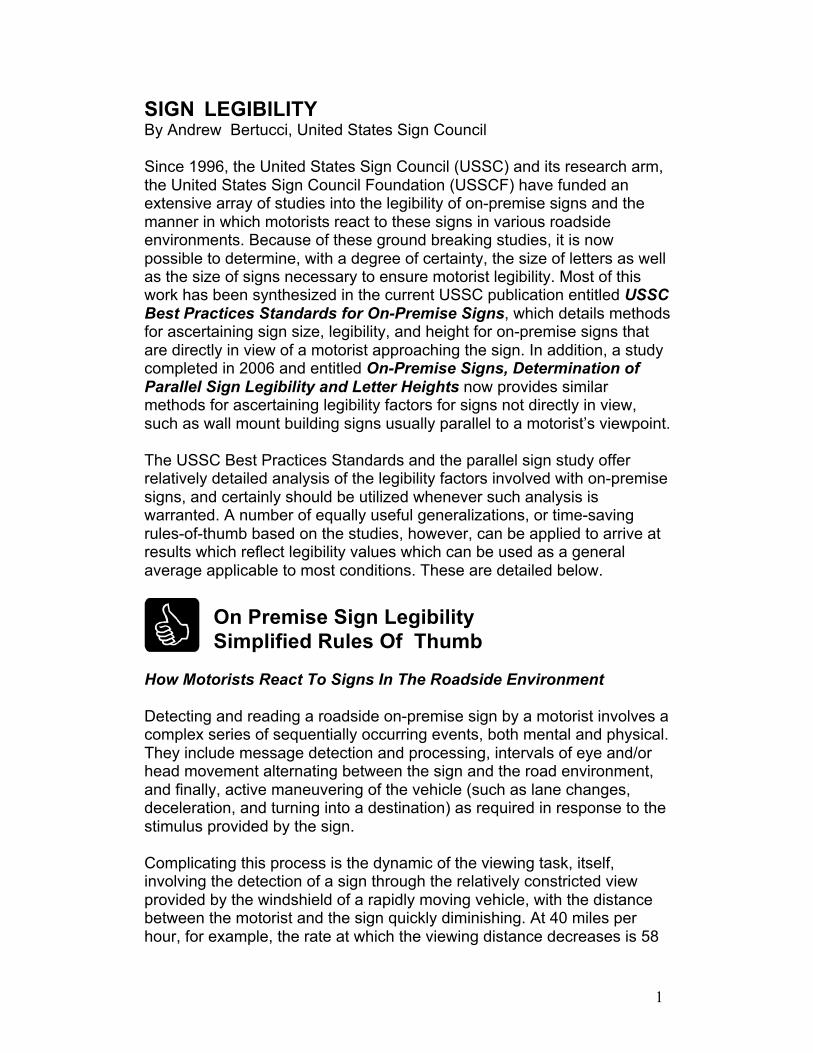
Perpendicular Signs
Figure 1. Perpendicular Sign Types
3
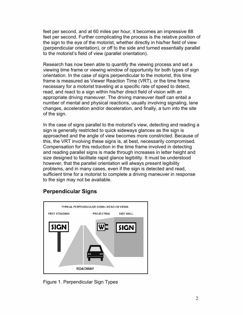
Perpendicular signs include most free standing signs, projecting signs, and, in some cases, flat wall signs placed on building walls that directly face on-coming traffic. (see figure 1). These signs are generally placed close to property lines and fall into the motorist’s so-called “cone of vision”, which is a view down the road encompassing ten degrees to the right or left of the eye, or twenty degrees total view angle. Signs falling within this cone can usually be viewed comfortably without excessive eye or head movement, and generally can be kept in the motorist’s line-of-sight from the time they are first detected until they are passed. (see figure 2, cone of vision).
Figure 2. Cone of Vision
Because of this relatively constant view window, perpendicular signs can be designed and sized to provide for viewing time sufficient to allow for adequate detection, reading, and driving maneuvers. The key to providing adequate viewing time is an understanding of Viewer Reaction Time and Viewer Reaction Distance, and how these factors can be computed to provide for adequate letter heights and sign sizes under varied traffic conditions and vehicle speeds.
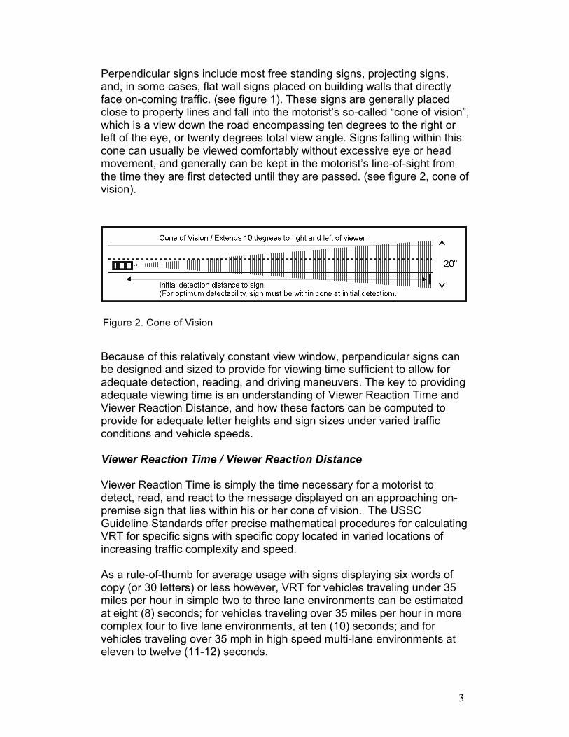
Viewer Reaction Time / Viewer Reaction Distance
Viewer Reaction Time is simply the time necessary for a motorist to detect, read, and react to the message displayed on an approaching on- premise sign that lies within his or her cone of vision. The USSC Guideline Standards offer precise mathematical procedures for calculating VRT for specific signs with specific copy located in varied locations of increasing traffic complexity and speed.
As a rule-of-thumb for average usage with signs displaying six words of copy (or 30 letters) or less however, VRT for vehicles traveling under 35 miles per hour in simple two to three lane environments can be estimated at eight (8) seconds; for vehicles traveling over 35 miles per hour in more complex four to five lane environments, at ten (10) seconds; and for vehicles traveling over 35 mph in high speed multi-lane environments at eleven to twelve (11-12) seconds.
4
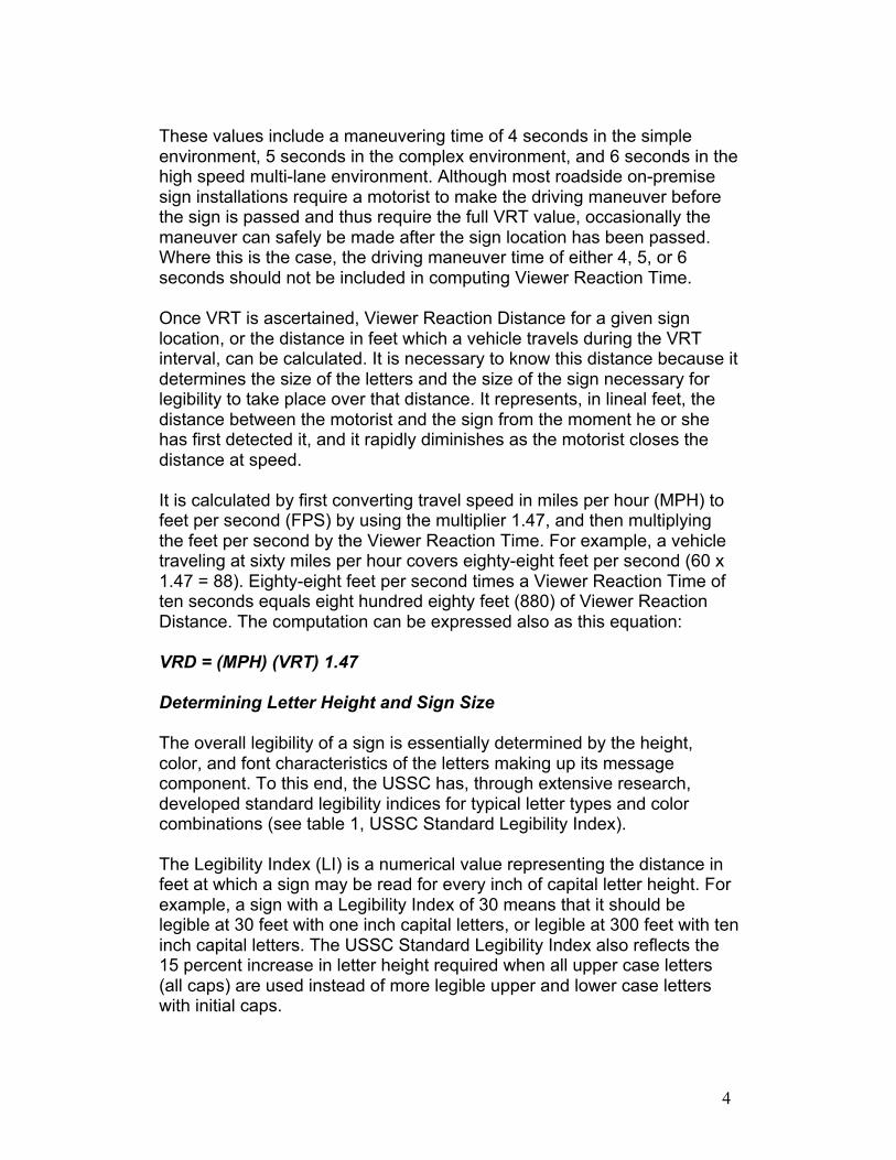
These values include a maneuvering time of 4 seconds in the simple environment, 5 seconds in the complex environment, and 6 seconds in the high speed multi-lane environment. Although most roadside on-premise sign installations require a motorist to make the driving maneuver before the sign is passed and thus require the full VRT value, occasionally the maneuver can safely be made after the sign location has been passed. Where this is the case, the driving maneuver time of either 4, 5, or 6 seconds should not be included in computing Viewer Reaction Time.
Once VRT is ascertained, Viewer Reaction Distance for a given sign location, or the distance in feet which a vehicle travels during the VRT interval, can be calculated. It is necessary to know this distance because it determines the size of the letters and the size of the sign necessary for legibility to take place over that distance. It represents, in lineal feet, the distance between the motorist and the sign from the moment he or she has first detected it, and it rapidly diminishes as the motorist closes the distance at speed.
It is calculated by first converting travel speed in miles per hour (MPH) to feet per second (FPS) by using the multiplier 1.47, and then multiplying the feet per second by the Viewer Reaction Time. For example, a vehicle traveling at sixty miles per hour covers eighty-eight feet per second (60 x 1.47 = 88). Eighty-eight feet per second times a Viewer Reaction Time of ten seconds equals eight hundred eighty feet (880) of Viewer Reaction Distance. The computation can be expressed also as this equation:
VRD = (MPH) (VRT) 1.47
Determining Letter Height and Sign Size
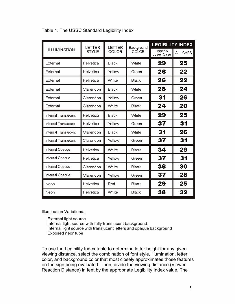
The overall legibility of a sign is essentially determined by the height, color, and font characteristics of the letters making up its message component. To this end, the USSC has, through extensive research, developed standard legibility indices for typical letter types and color combinations (see table 1, USSC Standard Legibility Index).
The Legibility Index (LI) is a numerical value representing the distance in feet at which a sign may be read for every inch of capital letter height. For example, a sign with a Legibility Index of 30 means that it should be legible at 30 feet with one inch capital letters, or legible at 300 feet with ten inch capital letters. The USSC Standard Legibility Index also reflects the 15 percent increase in letter height required when all upper case letters (all caps) are used instead of more legible upper and lower case letters with initial caps.
5
Table 1. The USSC Standard Legibility Index
Illumination Variations:
External light source Internal light source with fully translucent background Internal light source with translucent letters and opaque background Exposed neon tube
To use the Legibility Index table to determine letter height for any given viewing distance, select the combination of font style, illumination, letter color, and background color that most closely approximates those features on the sign being evaluated. Then, divide the viewing distance (Viewer Reaction Distance) in feet by the appropriate Legibility Index value. The
6
result is the letter height in inches for the initial capital letter in upper and lower case configurations, or for every letter in an all caps configuration. For example, if the Viewer Reaction Distance is 600 feet, and the Legibility Index is 30, the capital letter height would be 20 inches (600’/30 = 20”).
VRD (in feet) / LI = Letter Height (in inches)
The Legibility Index rule-of-thumb…30
In addition to the use of the Legibility Index chart, a simpler, rule-of-thumb Legibility Index of 30 is frequently used as an average to address most legibility requirements. Although generally acceptable, it should be understood that this is an average only, and it may fall short of meeting the legibility needs of any specific sign or environment. The USSC On- Premise Sign Standards provides a much more precise means of establishing this requirement, particularly for complex environments, and should be used whenever such precision is warranted.
Sign Copy Area and Negative Space – Computing Sign Size
The computation of overall sign size is of vital concern to anyone involved in designing or building on-premise signs, since it relates directly to both sign cost as well as to adherence to local building and zoning ordinances. It is for this reason that USSC has devoted so much research resources into developing methods for computing adequate sign sizes for varied environments, and into providing the industry with the means to compute the size of signs necessary to adequately transmit communicative messages to motorists traveling at different rates of speed. The use of the Legibility Index is the vital first step in this process, but there is frequently more involved than just letter height, especially in perpendicular signs involving the use of background panels. Clearly, in these instances, an understanding of how sign copy area and negative space interact to bring about optimum viewer legibility is critical.
In instances in which only letters comprise the total sign, such as channel letters on building walls, however, the computation of total sign size in square feet is relatively simple. In the case of these types of individual letter signs, overall size is frequently considered as the product of the height of the letters times the length of the line of letters. For example, if capital letter height is two feet, and the line of letters measures thirty feet horizontally, sign size would be calculated at sixty square feet (2 x 30 = 60). There is an important exception to this mode of calculation in which only the space actually taken up by the letters themselves in square feet, and not the space between letters, is considered. In these cases, overall size becomes simply the sum of all the individual letter areas, and is generally a fairer method of computation when the letters and or/symbols
7
are spread out over a large area of building wall. In any event, for individual letter signs, it is essentially the height of the letters which is the prime determinant of overall sign size, and as we observed above, this can be calculated with some precision through use of the Legibility Index.
In this context, there is also another useful rule of thumb which can be used to give a working approximation of how much horizontal length a given number of letters would require once the letter height is established by simply multiplying capital letter height by the number of letters. For average fonts, this rule of thumb takes into account the space between letters in a line (usually 1/3 the width of an individual letter and referenced as letterspace) and can give a surprisingly close determination of the actual length of the line of letters.
In the case of signs utilizing background areas, however, computation of the amount of space occupied by the lettering, also called copy area, is only the first step in computing overall sign size. Of equal importance in signs of this type is the amount of negative space surrounding the letters or copy area. It is this negative space which provides the background for the letters, makes legibility possible, and which must be accounted for in any computation to determine overall sign size.
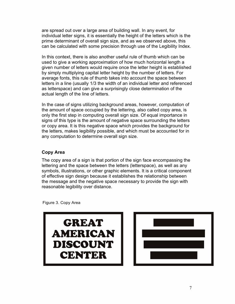
Copy Area The copy area of a sign is that portion of the sign face encompassing the lettering and the space between the letters (letterspace), as well as any symbols, illustrations, or other graphic elements. It is a critical component of effective sign design because it establishes the relationship between the message and the negative space necessary to provide the sign with reasonable legibility over distance.
Figure 3. Copy Area
8
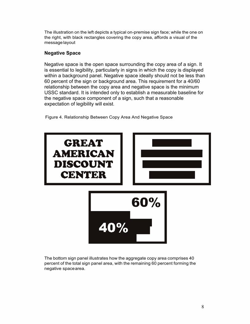
The illustration on the left depicts a typical on-premise sign face; while the one on the right, with black rectangles covering the copy area, affords a visual of the message layout
Negative Space
Negative space is the open space surrounding the copy area of a sign. It is essential to legibility, particularly in signs in which the copy is displayed within a background panel. Negative space ideally should not be less than 60 percent of the sign or background area. This requirement for a 40/60 relationship between the copy area and negative space is the minimum USSC standard. It is intended only to establish a measurable baseline for the negative space component of a sign, such that a reasonable expectation of legibility will exist.
Figure 4. Relationship Between Copy Area And Negative Space
The bottom sign panel illustrates how the aggregate copy area comprises 40 percent of the total sign panel area, with the remaining 60 percent forming the negative space area.
9
DETERMINING SIGN SIZE – Calculation Methodology
The size of a sign is determined by the size and length of the message and the time required to read and understand it. It can be calculated once the numerical values of the five size determinants –Viewer Reaction Time, Viewer Reaction Distance, Letter Height, Copy Area, and Negative Space – have been established.
The step-by-step process to determine sign size, which is explained below, is useful not only as a calculation method, but also as a means of understanding the elements involved in the calculation.
Area of Sign / Computation Process:
1. Determine speed of travel (MPH) in feet per second (FPS): (MPH x
1.47).
2. Determine Viewer Reaction Time (VRT).
3. Determine Viewer Reaction Distance (VRT x FPS).
4. Determine Letter Height in inches by reference to the Legibility
Index (LI): (VRD/LI).
5. Determine Single Letter Area in square inches (square the letter
height to obtain area occupied by single letter and its adjoining
letterspace).
6. Determine Single Letter Area in square feet: Single Letter Area in
square inches/144).
7. Determine Copy Area (Single Letter Area in square feet x total
number of letters plus area of any symbols in square feet).
8. Determine Negative Space Area at 60% of Sign Area (Copy Area x
1.5).
9. Add Copy Area to Negative Space Area.
10. Result is Area of Sign in square feet.
10
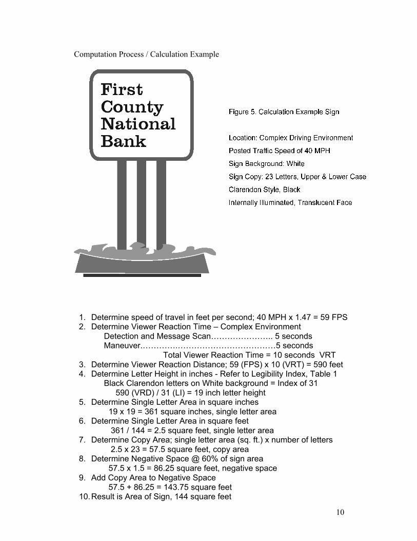
Computation Process / Calculation Example
1. Determine speed of travel in feet per second; 40 MPH x 1.47 = 59 FPS 2. Determine Viewer Reaction Time – Complex Environment
Detection and Message Scan………………….. 5 seconds Maneuver.………….………………………………5 seconds
Total Viewer Reaction Time = 10 seconds VRT 3. Determine Viewer Reaction Distance; 59 (FPS) x 10 (VRT) = 590 feet 4. Determine Letter Height in inches - Refer to Legibility Index, Table 1
Black Clarendon letters on White background = Index of 31 590 (VRD) / 31 (LI) = 19 inch letter height
5. Determine Single Letter Area in square inches 19 x 19 = 361 square inches, single letter area
6. Determine Single Letter Area in square feet 361 / 144 = 2.5 square feet, single letter area
7. Determine Copy Area; single letter area (sq. ft.) x number of letters 2.5 x 23 = 57.5 square feet, copy area
8. Determine Negative Space @ 60% of sign area 57.5 x 1.5 = 86.25 square feet, negative space
9. Add Copy Area to Negative Space 57.5 + 86.25 = 143.75 square feet
10. Result is Area of Sign, 144 square feet
11
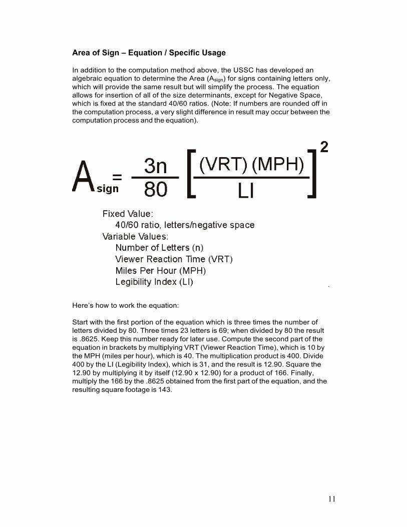
Area of Sign – Equation / Specific Usage
In addition to the computation method above, the USSC has developed an algebraic equation to determine the Area (Asign) for signs containing letters only, which will provide the same result but will simplify the process. The equation allows for insertion of all of the size determinants, except for Negative Space, which is fixed at the standard 40/60 ratios. (Note: If numbers are rounded off in the computation process, a very slight difference in result may occur between the computation process and the equation).
.
Here’s how to work the equation:
Start with the first portion of the equation which is three times the number of letters divided by 80. Three times 23 letters is 69; when divided by 80 the result is .8625. Keep this number ready for later use. Compute the second part of the equation in brackets by multiplying VRT (Viewer Reaction Time), which is 10 by the MPH (miles per hour), which is 40. The multiplication product is 400. Divide 400 by the LI (Legibility Index), which is 31, and the result is 12.90. Square the 12.90 by multiplying it by itself (12.90 x 12.90) for a product of 166. Finally, multiply the 166 by the .8625 obtained from the first part of the equation, and the resulting square footage is 143.
12
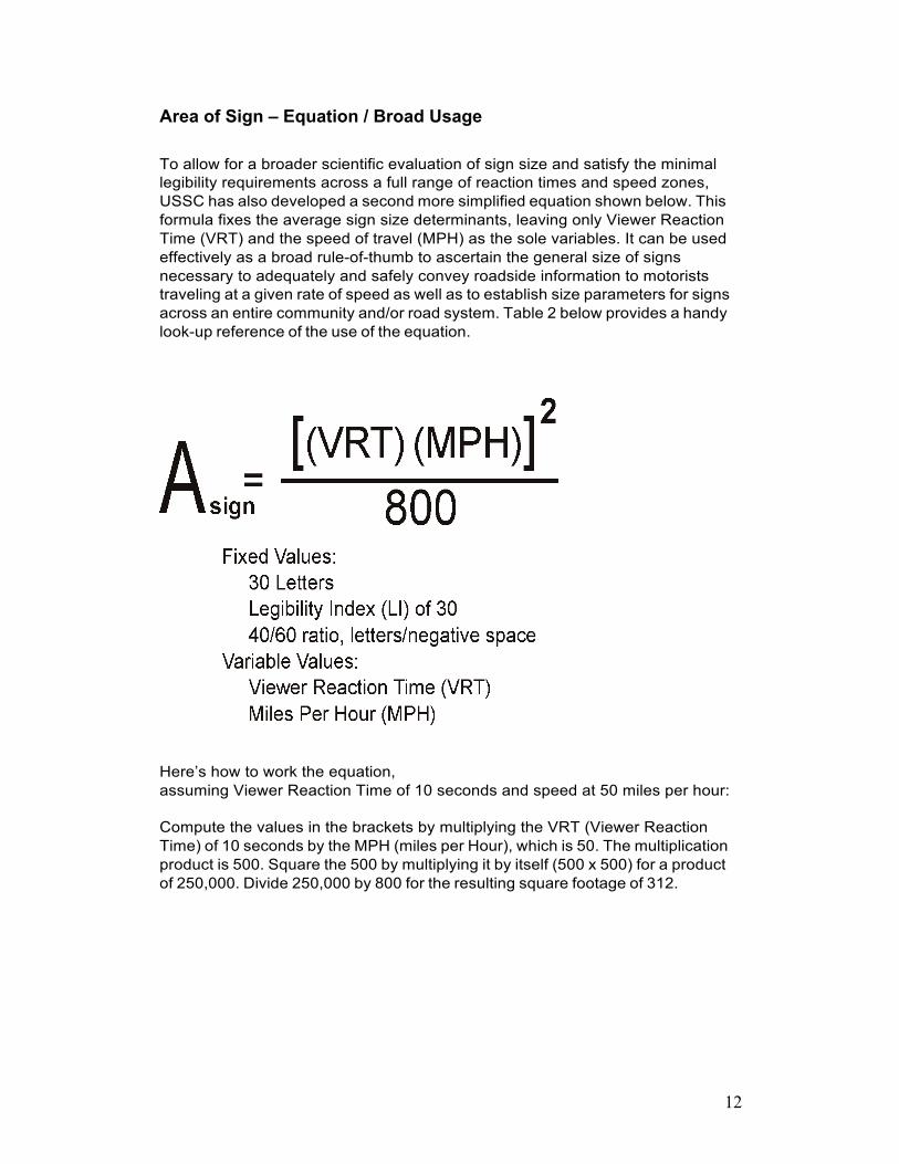
Area of Sign – Equation / Broad Usage
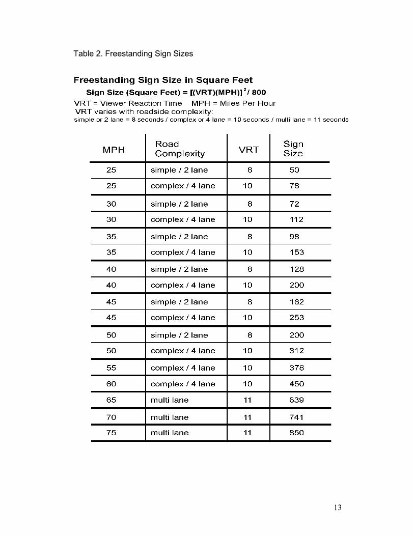
To allow for a broader scientific evaluation of sign size and satisfy the minimal legibility requirements across a full range of reaction times and speed zones, USSC has also developed a second more simplified equation shown below. This formula fixes the average sign size determinants, leaving only Viewer Reaction Time (VRT) and the speed of travel (MPH) as the sole variables. It can be used effectively as a broad rule-of-thumb to ascertain the general size of signs necessary to adequately and safely convey roadside information to motorists traveling at a given rate of speed as well as to establish size parameters for signs across an entire community and/or road system. Table 2 below provides a handy look-up reference of the use of the equation.
Here’s how to work the equation, assuming Viewer Reaction Time of 10 seconds and speed at 50 miles per hour:
Compute the values in the brackets by multiplying the VRT (Viewer Reaction Time) of 10 seconds by the MPH (miles per Hour), which is 50. The multiplication product is 500. Square the 500 by multiplying it by itself (500 x 500) for a product of 250,000. Divide 250,000 by 800 for the resulting square footage of 312.
13
Table 2. Freestanding Sign Sizes

14
Illustration from Street Graphics and the Law, American Planning Association, 2004
15
Parallel Signs
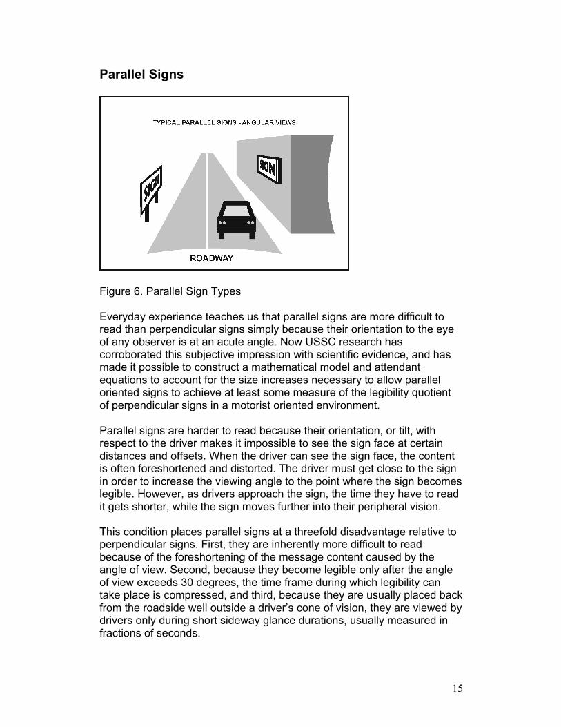
Figure 6. Parallel Sign Types
Everyday experience teaches us that parallel signs are more difficult to read than perpendicular signs simply because their orientation to the eye of any observer is at an acute angle. Now USSC research has corroborated this subjective impression with scientific evidence, and has made it possible to construct a mathematical model and attendant equations to account for the size increases necessary to allow parallel oriented signs to achieve at least some measure of the legibility quotient of perpendicular signs in a motorist oriented environment.
Parallel signs are harder to read because their orientation, or tilt, with respect to the driver makes it impossible to see the sign face at certain distances and offsets. When the driver can see the sign face, the content is often foreshortened and distorted. The driver must get close to the sign in order to increase the viewing angle to the point where the sign becomes legible. However, as drivers approach the sign, the time they have to read it gets shorter, while the sign moves further into their peripheral vision.
This condition places parallel signs at a threefold disadvantage relative to perpendicular signs. First, they are inherently more difficult to read because of the foreshortening of the message content caused by the angle of view. Second, because they become legible only after the angle of view exceeds 30 degrees, the time frame during which legibility can take place is compressed, and third, because they are usually placed back from the roadside well outside a driver’s cone of vision, they are viewed by drivers only during short sideway glance durations, usually measured in fractions of seconds.
16
In many cases, their orientation causes not only severely compromised legibility compared to perpendicular signs, but results in the sign not being seen at all. In the USSC study, Real World On-Premise Sign Visibility, in which people were asked to drive through typical suburban shopping areas and locate specific signs, perpendicular signs were almost never missed while the subjects drove past 30 percent of the parallel signs, even though the parallel signs were two and three times larger than the perpendicular signs and the drivers were actively looking for them.
Parallel signs, therefore, must be read using a series of very quick glances at large visual angles during small windows of opportunity. Because of this, letter heights developed for perpendicular signs, where drivers have more time and can take longer straight ahead glances, cannot provide for adequate parallel sign legibility.
As we have noted in the case of perpendicular signs, the minimum distance at which a sign must become legible is a function of the time it takes to read the sign and the decisions and maneuvers required to comply with the sign. This is the Viewer Reaction time (VRT), which when combined with the speed of travel, becomes the Viewer Reaction Distance (VRD). Given the VRD, a perpendicular sign’s letter height can be calculated using the Legibility Index.
The legibility of parallel signs, however, depends not on a driver’s line of sight to a sign down the road, but rather when the sign becomes visible to the driver at a sight angle sufficient to allow at least some glance legibility to take place. A significant amount of research has now determined that this angle should be no less than 30 degrees to the driver’s line of sight, and it is the visual restriction imposed by this angle, along with the number of lanes of travel, and the sign’s offset from the curb, which determines the Maximum Available Legibility Distance, (or MALD) for a given parallel sign
While traversing this distance, however, a driver cannot be expected to register much more than a few quick glances at the sign without adversely affecting his/her view of the road. Thus it is essential to optimize reading speed for parallel signs in order to minimize the duration and frequency of glances that drivers must make to read the sign. Research has shown that reading speed increases to its maximum as letters are enlarged by a factor of three, and then tends to level off; and to ensure adequate letter height for parallel signs, a multiplier of three is used in the mathematical model to determine the letter heights and the legibility index for parallel signs.
Using this multiplier of three as a benchmark or rule of thumb, the Legibility Index for parallel signs falls to 10, instead of the Legibility Index of 30 we have shown as a rule of thumb for perpendicular signs. Thus a
17
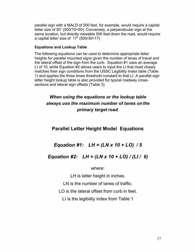
parallel sign with a MALD of 500 feet, for example, would require a capital letter size of 50” (500/10=50). Conversely, a perpendicular sign at the same location, but directly viewable 500 feet down the road, would require a capital letter size of 17” (500/30=17)
Equations and Lookup Table The following equations can be used to determine appropriate letter heights for parallel mounted signs given the number of lanes of travel and the lateral offset of the sign from the curb. Equation #1 uses an average LI of 10, while Equation #2 allows users to input the LI that most closely matches their sign conditions from the USSC Legibility Index table (Table 1) and applies the three times threshold constant to that LI. A parallel sign letter height lookup table is also provided for typical roadway cross- sections and lateral sign offsets (Table 3).
When using the equations or the lookup table always use the maximum number of lanes on the
primary target road.
Parallel Letter Height Model Equations
Equation #1: LH = (LN x 10 + LO) / 5
Equation #2: LH = (LN x 10 + LO) / (LI / 6)
where:
LH is letter height in inches.
LN is the number of lanes of traffic.
LO is the lateral offset from curb in feet.
LI is the legibility index from Table 1
18
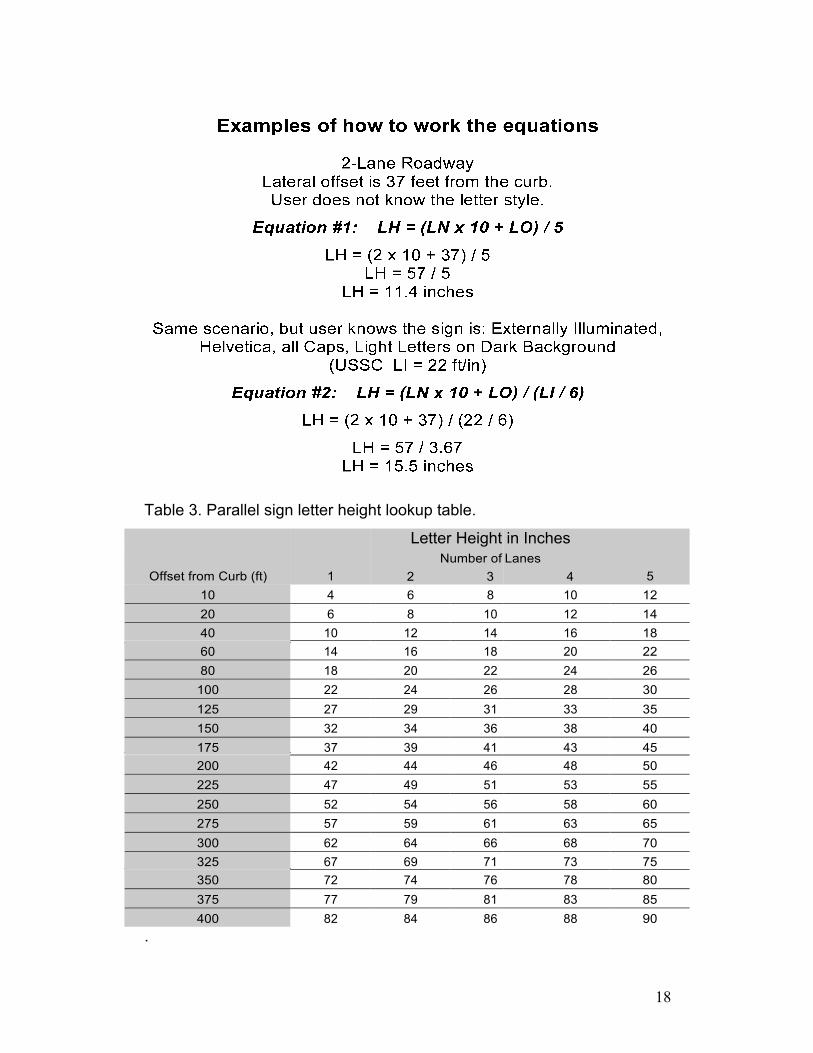
Table 3. Parallel sign letter height lookup table.
Offset from Curb (ft)
1
Letter Height Number of
2 3
in Inches Lanes
4
5 10 4 6 8 10 12 20 6 8 10 12 14 40 10 12 14 16 18 60 14 16 18 20 22 80 18 20 22 24 26 100 22 24 26 28 30 125 27 29 31 33 35 150 32 34 36 38 40 175 37 39 41 43 45 200 42 44 46 48 50 225 47 49 51 53 55 250 52 54 56 58 60 275 57 59 61 63 65 300 62 64 66 68 70 325 67 69 71 73 75 350 72 74 76 78 80 375 77 79 81 83 85 400 82 84 86 88 90
.