size-dependent flexural dynamics of ribs-connected
TRANSCRIPT
Copyright © 2014 Tech Science Press CMC, vol.42, no.2, pp.141-174, 2014
Size-Dependent Flexural Dynamics of Ribs-ConnectedPolymeric Micropanels
K.B. Mustapha1,2
Abstract: This study investigates the sensitivity of the flexural response of a rib-connected system of coupled micro-panels with traction-free surfaces. Idealized asa two-dimensional elastic continuum with a finite transverse stiffness, each micro-panels’ behavior is examined within the framework of the biharmonic mathemati-cal model derived from the higher-order, size-dependent strain energy formulation.The model incorporates the material length scale, which bears an associative re-lationship with the underlying polymer’s averaged Frank elastic constant. Upperestimates of the eigenvalue of the system, under fully clamped edges and simply-supported edges, are determined by the Rayleigh method. The adopted theory forthe micro-panel’s behavior takes into account the rotary inertia, the small-scale ef-fect, the Poisson’s ratio and the effective stiffness of the ribs, but neglects sheardistortion. Frequency shifts of the rib-connected coupled micro-panels are system-atically identified and presented. Results indicate the critical thickness for whichthe polymeric micro-panel’s resonant frequency starts to experience stiffened re-sponses based on the magnitude of the size-effect. The Rayleigh method of eigen-value extraction is augmented with the applied statistical method of design of ex-periment for the discovery of notable interaction effects between the aspect ratio,rotary inertia, small-scale effect, and thickness-to-span ratio of the system.
Keywords: Modified couple stress, Micro plates, Size-effect, Vibration, Rayleighmethod.
1 Introduction
Microelectromechanical and nanoelectromechanical systems (MEMs and NEMS)occupy preeminent functional roles within the landscape of next generation devices.Often endowed with micro-sized structures, MEMs and NEMs have found unal-
1 Faculty of Engineering, Computing and Science, Swinburne University of Technology (SarawakCampus), Jalan Simpang Tiga, Kuching 93350, Sarawak, Malaysia.
2 Corresponding author. Tel: +6082260656; E-mail: [email protected]
142 Copyright © 2014 Tech Science Press CMC, vol.42, no.2, pp.141-174, 2014
loyed advantage in portable field accelerometers, electrical filters, hydrophones,high-Q oscillators and inertia sensors [Nguyen (1995); Yazdi, Ayazi and Najafi(1998); Kun and Nguyen (1999); Mattila, Kiihamäki, Lamminmäki, Jaakkola,Rantakari, Oja, Seppä, Kattelus and Tittonen (2002)]. A number of reasons shapethe adoption of micro-systems across different emerging scientific fields: (i) prodi-gious capacity for fast response; (ii) ultra-high resonating frequency; and (iii) ahigh sensitivity to changes in stimulus.
The complexity of most microsystems depends on the intended functional pur-pose and operational requirements. In a simple form, a microsystem comprisescantilever arrays along with some other functional embodiment. In a more com-plex form, however, it may be composed of structural elements with differentgeometrical parameters for different functional purposes [Boisen, Dohn, Keller,Schmid and Tenje (2011)]. Among the unique set of structural elements rou-tinely employed in MEMs is the two-dimensional plate-like micro-scale struc-tures (e.g. thin film, micro-scale panels, and orthotropic micron metallic web[Benkhelifa, Farnsworth, Tiwari and Bandi (2010)]. These micro-structural ele-ments have excellent magnetic, optical, mechanical and electrical properties thatmake them resourceful in specific applications like thermal sealing and energy har-vesting [Sakhaee-Pour, Ahmadian and Vafai (2008); Liu, Tu and Chung (2012);Manzaneque, Ruiz, Hernando-Garcia, Ababneh, Seidel and Sanchez-Rojas (2012)]Since the optimal design of MEMs and NEMs impels the understanding of theirresponse under disparate mechanical loadings, the analyses of their constituentmicro-structural elements has gained attention in the past few years [Younis (2011)].During the operational life of MEMs, some factors compromise the exhibitionof their intended performance [Ardito, Baldasarre, Corigliano, De Masi, Frangiand Magagnin (2013)]. Frequently, such factors are closely related to the inter-relationship between the mechanical parameters of the underlying materials andthe geometric parameters of the system’s architecture. This interplay imposes astrict constrain on the predictability of MEMs’ mechanical responses.
Several studies relating to the prediction of MEMs’ response have revealed the de-mands for the refinement of the mathematical models of the constituent elements ofthese miniature devices [Peddieson, Buchanan and McNitt (2003); Reddy (2011);Mustapha (2014)]. This is because, at small length scale, the vexing contributionof size-effect to the response of the structures starts to set in. Initial studies onthe modeling of micro-scale structures through the framework of computationalmechanics, employed the classical continuum theory (CCT). However, the under-lying assumptions of the CCT do not account for the contribution of the latent size-dependency that manifests in micro and nano-scale structures [Fleck and Hutchin-son (1993); Georgiadis and Velgaki (2003); Liew, Wong, He, Tan and Meguid
Size-Dependent Flexural Dynamics of Ribs-Connected Polymeric Micropanels 143
(2004); Uchic, Dimiduk, Florando and Nix (2004); Volkert and Lilleodden 2006;Mahdavi, Farshidianfar, Tahani, Mahdavi and Dalir (2008); Chiroiu, Munteanu andDelsanto (2010)]. It is this deficiency of the CCT that has ignited the adoption of anumber of enriched microstructure-dependent elasticity theories with higher-orderconstitutive laws [Farokhi, Ghayesh and Amabili (2013)]. The models derived fromthese higher-order theories contain additional material constants, along with thewell-known Lamé constants, to address the quantification of the phenomenologicalsize-specific property.
Evidently, attempt on the theoretical modeling of microstructured materials stretchesback to the work of the Cosserat brothers [Cosserat E. and F (1909); Chiroiu,Munteanu and Gliozzi (2010)]. Consolidating on the work of the Cosserat broth-ers, a select list of advanced continuum theories that have emerged to be of relevantto the modeling of microstructured materials include the Eringen’s nonlocal elas-ticity theory [Eringen (1972); Eringen and Edelen (1972); Fotouhi, Firouz-Abadiand Haddadpour (2013)], the strain gradient theory [Aifantis (1992); Tang, Shenand Atluri (2003); Papacharalampopoulos, Karlis, Charalambopoulos and Polyzos(2010)], the couple stress theory [Toupin (1962); Yang, Chong, Lam and Tong(2002)] and the micropolar elasticity [Toupin (1962); Xie and Long (2006); Marin,Agarwal and Othman (2014)]. A concise summary of the distinction between thesetheories is well-stated in Aifantis [Aifantis (2011)]. Meanwhile, a well-foundedchallenge with the new higher-order models is the difficulty associated with the de-termination of the microstructure-dependent material constants introduced by thesetheories [Lam, Yang, Chong, Wang and Tong (2003)]. Consequently, models ofthe structural elements with fewer length scale parameters offer both experimentalbenefit and mathematical convenience. The modified couple stress theory (MCST),which is adopted in the current study, is one such higher-order elasticity theories.With the MCST, the characterization of size-effect is done with just one materiallength scale parameter [Yang, Chong, Lam and Tong (2002); Papargyri-Beskou,Tsepoura, Polyzos and Beskos (2003)]. The MCST has already set off a burstof research activities in the theoretical prediction of the deformational responseof micro-scale structural elements. Initial application of the MCST focused onthe analyses of micro-scale beams, rods and micro-scale pipes [Anthoine (2000);Park and Gao (2006); Güven (2011); Reddy (2011); Mustapha and Zhong (2012);Mustapha and Zhong (2012); Akgöz and Civalek (2013); Wang, Liu, Ni and Wu(2013)]. However, a limited number of recent studies have also extended the workto the analyses of micro-scale plates [Yin, Qian, Wang and Xia (2010); Jome-hzadeh, Noori and Saidi (2011); Akgöz and Civalek (2013); Gao, Huang and Reddy(2013)] An experimental validation of the MCST is recently presented in Romanoffand Reddy (2014).
144 Copyright © 2014 Tech Science Press CMC, vol.42, no.2, pp.141-174, 2014
Drawing on the strength of the MCST, the present study investigates the size-dependent flexural vibration of a rib-connected system of micro-panels. The systemunder investigation is part of an on-going design of a polymeric vibration isolationpad for electronic communicating systems. For the derivation, each micro-panel istreated as a micro-scale plate with an internal material length scale. The stiffnessof the ribs between the micro-panel is derived by treating the ribs as a collectionof clamped-clamped elastic beams. A hybrid numerical experiment based on theRayleigh method of eigenvalue extraction and an applied statistical method of de-sign of experiment (DOE) is adopted for parametric analysis of the derived model.The adopted hybrid approach helps to illuminate the pattern of the resonant fre-quency shifts under varying influences of the stiffness of the ribs. The effects of thematerial length scale of the micro-panel, the Poisson’s ratio and the rotary inertiaare also assessed. The ensuing part of the paper proceeds with the presentationof the derivation of the size-dependent elastodynamics governing equation of thesystem in section 2. The solution procedure for the free vibration study is detailedin section 3. Reduced special cases of the derived model are highlighted in section4. In section 5, numerical results and the discussion of the influence of the model’sparameters on the frequency shift of the system are presented. Basic conclusionsfrom the analysis are given in section 6.
2 Variational Formulation
2.1 The higher-order elasticity theory
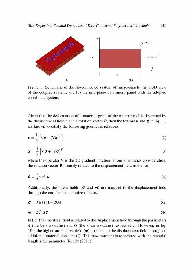
The system being considered is the elastically connected micro-panels shown inFig. 1. In what follows, the equations governing the flexural vibration of eachmicro-panel are derived from the Hamilton’s principle and the modified couplestress theory (MCST). In deriving the governing equation, we treat each micro-panel as an isotropic linear elastic body occupying a volume ∀. In line with the the-oretical framework of the MCST, the size-dependent strain energy of a deformedmicro-scale structure is characterized by a quartet of tensors related as [Yang,Chong, Lam and Tong (2002); Reddy (2011)]:
ΠU =12
∫∀(σσσ : εεε +mmm : χχχ)d∀. (1)
In general, the volume ∀ is taken to be an open set in R3 with a well-behaved surfaceboundary (see Fig. 1b for the unit normal to the boundaries’ of a micro-panel).Accordingly, ΠU , εεε and σσσ are the strain energy, the dilatation strain tensor andthe Cauchy stress tensor, respectively. Furthermore, the tensors mmm and χχχ refer tothe deviatoric components of the couple stress and the symmetric curvature tensor,respectively.
Size-Dependent Flexural Dynamics of Ribs-Connected Polymeric Micropanels 145
(a) (b)
Figure 1: Schematic of the rib-connected system of micro-panels: (a) a 3D viewof the coupled system; and (b) the mid-plane of a micro-panel with the adoptedcoordinate system.
Given that the deformation of a material point of the micro-panel is described bythe displacement field uuu and a rotation vector θθθ , then the tensors εεε and χχχ in Eq. (1)are known to satisfy the following geometric relations:
εεε =12
[∇uuu+(∇uuu)T
](2)
χχχ =12
[∇θθθ +(∇θθθ)T
](3)
where the operator ∇ is the 2D gradient notation. From kinematics consideration,the rotation vector θθθ is easily related to the displacement field in the form:
θθθ =12
curl uuu (4)
Additionally, the stress fields (σσσ and mmm) are mapped to the displacement fieldthrough the enriched constitutive rules as:
σσσ = λ tr(ε)I+2Gε (5a)
mmm = 2ζ2µχχχ (5b)
In Eq. (5a) the stress field is related to the displacement field through the parametersλ (the bulk modulus) and G (the shear modulus) respectively. However, in Eq.(5b), the higher-order stress field (mmm) is related to the displacement field through anadditional material constant (ζ ) This new constant is associated with the materiallength scale parameter [Reddy (2011)].

146 Copyright © 2014 Tech Science Press CMC, vol.42, no.2, pp.141-174, 2014
For the purpose of characterizing the deformation of the micro-panel through theabove higher-order constitutive rules, an infinitesimal bounded volume of the micro-panel is considered. The infinitesimal bounded volume of the micro-panel is treatedas a differentiable manifold embedded in a Euclidean 3-space ∀. Consequently, thefollowing displacement trial field holds:
uuu = u1iii+u2 jjj+u3kkk (6)
where u1,u2, and u3 are components of the displacement vector of an arbitrarymaterial point of the micro-panel in the x,y and z directions. Based on the small-deflection theory of thin plates, which rests on the Kirchhoff assumptions, each ofthese components of the displacement field is defined as:
u1 (x,y,z, t) = u(x,y, t)− z∂w(x,y, t)
∂x(7a)
u2 (x,y,z, t) = v(x,y, t)− z∂w(x,y, t)
∂y(7b)
u3 (x,y,z, t) = w(x,y, t) (7c)
where u, v, and w are displacement components in the x, y and z directions, respec-tively. Based on Eqs. (7a) – (7c), the non-zero components of the strain tensor areobtained as:
εxx =∂u∂x− z
∂ 2w∂x2 (8a)
εyy =∂v∂y− z
∂ 2w∂y2 (8b)
εxy = εyx =12
[∂u∂y
+∂v∂x−2z
∂ 2w∂y∂x
](8c)
The components of the rotation vector, from Eq. (4), are obtained as:
θx =∂w∂x
; θy =−∂w∂y
; θz =12
[−∂u
∂y+
∂v∂x
](9)
With the help of Eq. (9) bearing in mind Eq. (3), the components of the symmetriccurvature tensor, are derived as:
χxx =∂ 2w∂y∂x
; χyy =−∂ 2w∂y∂x
; χzz = 0 (10a)
χxy = χyx =12
[−∂ 2w
∂x2 +∂ 2w∂y2
](10b)
Size-Dependent Flexural Dynamics of Ribs-Connected Polymeric Micropanels 147
χzy = χyz =14
[− ∂ 2u
∂y∂x+
∂ 2v∂x2
](10c)
χzx = χxz =14
[−∂ 2u
∂y2 +∂ 2v
∂y∂x
](10d)
Given the above derived kinematic variables, the first variation of the microstructure-dependent strain energy is now written as:
δΠU =12
δ
∫ ∫ ∫ h/2
−h/2[
E(1− v2)
ε2xx +
E(1− v2)
ε2yy +
2vE(1− v2)
εyyεxx +Gε2yx+
G{ζ 2µ(χxx)
2 +ζ2µ(χyy)
2 +ζ2µ(2χxy)
2 +ζ2µ(2χyz)
2 +ζ2µ(2χxz)
2}]dxdydz(11)
From the displacement field defined in Eq. (7), the first variation of the kinetic en-ergy, with the rotary inertia included, is defined as [Reddy (2002); Szilard (2004)]:
δΠT =12
δ
∫ ∫ρh
[(∂u1
∂ t
)2
+
(∂u2
∂ t
)2
+
(∂u3
∂ t
)2]
dydx (12)
where ρ is the mass density and h is the constant thickness of the micro-panel.In the same spirit, the first variation of the virtual work done by external loads is[Akgöz and Civalek (2013)]:
T∫0
δΠWB =−∫
R( fiδui + ciδθi)−
∫∂R
(tiδui + siδθi)ds (13)
where fi,ci, ti and si are components of the body force, the body couple, the trac-tion and the surface couple, respectively. With Eqs. (11) – (13), one invokes thevariational statement of the Hamilton’s principle, which mathematically translatesto:
δT∫0(ΠT −ΠU +ΠWB)dt = 0 (14)
where the integration in Eq. (14) is carried out between the time interval (0,T ). Eqs.(11) – (13) are substituted in Eq. (14), and the fundamental lemma of variationalcalculus is invoked to retrieve the size-dependent governing equations of a singlemicro-panel as:
−ρh∂ 2u∂ t2 +Eh
[1
2(1+ v)∂ 2u∂y2 +
12(1− v)
∂ 2v∂y∂x
+1
1− v2∂ 2u∂x2
]+
Ehζ 2
8(1+ v)
[∂ 4v
∂y3∂x− ∂ 4u
∂y4 −∂ 4u
∂x2∂y2 +∂ 4v
∂x3∂y
]= 0
(15)

148 Copyright © 2014 Tech Science Press CMC, vol.42, no.2, pp.141-174, 2014
−ρh∂ 2v∂ t2 +Eh
[1
1− v2∂ 2v∂y2 +
12(1− v)
∂ 2u∂y∂x
+1
2(1+ v)∂ 2v∂x2
]+
Ehζ 2
8(1+ v)
[∂ 4u
∂y3∂x− ∂ 4v
∂x2∂y2 +∂ 4u
∂x3∂y+
∂ 4v∂x4
]= 0
(16)
−ρh∂ 2w∂ t2 +ρI
[∂ 4w
∂ t2∂y2 +∂ 4w
∂ t2∂x2
]− Eh3
12(1− v2)
[∂ 4w∂y4 +2
∂ 4w∂x2∂y2 +
∂ 4w∂x4
]− Ehζ 2
2(1+ v)
[∂ 4w∂y4 +2
∂ 4w∂x2∂y2 +
∂ 4w∂x4
]= 0
(17)
The terms that arise from the use of the MCST are underlined in Eqs. (15) – (17).In general, Eqs. (15) and (16) are adequate to predict the in-plane (extensional)vibration of a single micro-panel. On the other hand, Eq. (17) is suitable for thequantification of the transverse motion of a single micro-panel. Now, while Eq.(17) can be tackled alone, Eqs. (15) and (16) are coupled, and thus they cannotbe solved independent of each other. Of interest in this study is the case of twoinextensible micro-panels separated by evenly distributed ribs. On this premise,the focus of the current study is restricted to Eq(17) and its eigen-analysis. For thepurpose of incorporating the influence of the ribs, the following assumptions areadopted:
1. the ribs are made of similar materials and have resistance to stretching andcompression;
2. the ribs suffer negligibly marginal distortion of their positions with respectto their initial contact positions with the surface of each micro-panel;
3. no structural anisotropy is introduced by the ribs and;
4. the two micro-panels are made of the same material, length, width and den-sity.
With the stated assumptions, the concentrated rigidities of the ribs can be replacedby the distributed continuous support of the Winkler’s type. Given this simplifica-tion, the contribution of the ribs’ stiffness is now reflected in the equation governingthe transverse vibration of individual micro-panel as:
Size-Dependent Flexural Dynamics of Ribs-Connected Polymeric Micropanels 149
Upper micro-panel:
−ρh∂ 2wu
∂ t2 +ρI[
∂ 4wu
∂ t2∂y2 +∂ 4wu
∂ t2∂x2
]− Eh3
12(1− v2)
[∂ 4wu
∂y4 +2∂ 4wu
∂x2∂y2 +∂ 4wu
∂x4
]− Ehζ 2
2(1+ v)
[∂ 4wu
∂y4 +2∂ 4wu
∂x2∂y2 +∂ 4wu
∂x4
]−K (wu−wl) = 0
(18)
Lower micro-panel:
−ρh∂ 2wl
∂ t2 +ρI[
∂ 4wl
∂ t2∂y2 +∂ 4wl
∂ t2∂x2
]− Eh3
12(1− v2)
[∂ 4wl
∂y4 +2∂ 4wl
∂x2∂y2 +∂ 4wl
∂x4
]− Ehζ 2
2(1+ v)
[∂ 4wl
∂y4 +2∂ 4wl
∂x2∂y2 +∂ 4wl
∂x4
]−K (wl−wu) = 0
(19)
It is pointed out that in Eqs. (18) – (19), the total stiffness (K) of the Winkler’sfoundation is taken to be equivalent to the averaged stiffness of the overall ribsbetween the micro-panels. Besides, wu and wl denote the transverse motions of theupper and lower micro-panel, respectively. The two displacement field variablesdescribing the response of each micro-panel are homogenized by subtracting Eq.(19) from (18) to get:
−ρh∂ 2 (wu−wl)
∂ t2 +ρI[
∂ 4
∂ t2∂y2 +∂ 4
∂ t2∂x2
](wu−wl)
− Eh3
12(1− v2)
[∂ 4
∂y4 +2∂ 4
∂x2∂y2 +∂ 4
∂x4
](wu−wl)
− Ehζ 2
2(1+ v)
[∂ 4
∂y4 +2∂ 4
∂x2∂y2 +∂ 4
∂x4
](wu−wl)−2K (wu−wl) = 0
(20)
A further modification of the system’s response is sought by employing a change ofvariable as done in Murmu and Adhikari (2011). In this vein, the relative displace-ment (wu−wl) of the upper micro-panel with respect to the lower micro-panel isdenoted by wa. The change of variable leads to the equations of the rib-connectedmicro-panels as:
−ρh∂ 2wa
∂ t2 +ρI[
∂ 4
∂ t2∂y2 +∂ 4
∂ t2∂x2
]wa
− Eh3
12(1− v2)
[∂ 4
∂y4 +2∂ 4
∂x2∂y2 +∂ 4
∂x4
]wa
− Ehζ 2
2(1+ v)
[∂ 4
∂y4 +2∂ 4
∂x2∂y2 +∂ 4
∂x4
]wa−2Kwa = 0
(21)

150 Copyright © 2014 Tech Science Press CMC, vol.42, no.2, pp.141-174, 2014
−ρh∂ 2wl
∂ t2 +ρI[
∂ 4wl
∂ t2∂y2 +∂ 4wl
∂ t2∂x2
]wa−
Eh3
12(1− v2)
[∂ 4wl
∂y4 +2∂ 4wl
∂x2∂y2 +∂ 4wl
∂x4
]− Ehζ 2
2(1+ v)
[∂ 4wl
∂y4 +2∂ 4wl
∂x2∂y2 +∂ 4wl
∂x4
]+Kwa = 0
(22)
Equations (21) and (22) describe the transverse motion of the connected micro-panels, where I is the moment of inertia per unit area of a micro-panel. It de-serves to be pointed out that if the underlined terms are eliminated, the classicalsize-independent governing equation of the Kirchhoff plate theory is retrieved. Insucceeding sections, the dynamic behavior of the system is investigated under twoidealized boundary conditions: (i) simple support on the four edges (that is, SSSS,where S stands for simply-supported); and (ii) a built-in support on the four edges(that is, CCCC, where C stands for clamped) as shown in Fig. 2.
Figure 2: The two types of boundary supports investigated for the rib-connectedmicro-panels.
Size-Dependent Flexural Dynamics of Ribs-Connected Polymeric Micropanels 151
In order to specify the expressions for the stipulated boundary conditions the fol-lowing stress resultants are defined:
Cxx
Cxy
Cxz
Cyy
Cyz
=h/2∫−h/2
mxx
mxy
mxz
myy
myz
dz (23)
Mxx
Mxy
Myy
=h/2∫−h/2
σxx
σxy
σyy
zdz (24)
where Cxx,Cxy,CxzCyy and Cyz are the couple moments that need to be mapped to thedisplacement field through Eq. (10). Also, MMMxx,MMMxy and MMMyy are the moments (re-lated to the Cauchy stress tensor) that are mapped to the displacement field throughEq. (8). Under the SSSS boundary condition, the following constraints are imposedaround the periphery of the coupled micro-panels:
wa (0,y, t) = wu (0,y, t)−wl (0,y, t) = 0 (25)
wa (a,0, t) = wu (a,0, t)−wl (a,0, t) = 0 (26)
wa (x,0, t) = wu (x,0, t)−wl (x,0, t) = 0 (27)
wa (x,b, t) = wu (x,b, t)−wl (x,b, t) = 0 (28)
Mxxa (0,y, t)+Cxya (0,y, t) = 0 (29)
Mxxa (a,y, t)+Cxya (a,y, t) = 0 (30)
−Myya (x,0, t)+Cxya (x,0, t) = 0 (31)
−Myya (x,b, t)+Cxya (x,b, t) = 0 (32)
Analogously, under the CCCC boundary condition the expressions stated in Eqs.(25) – (28), are supplemented with the following additional constraints around theperiphery of coupled micro-panels:
∂
∂xwa (0,y, t) =
∂
∂x[wu (0,y, t)−wl (0,y, t)] = 0 (33)
∂
∂xwa (a,0, t) =
∂
∂x[wu (a,0, t)−wl (a,0, t)] = 0 (34)
∂
∂xwa (x,0, t) =
∂
∂x[wu (x,0, t)−wl (x,0, t)] = 0 (35)
∂
∂xwa (x,b, t) =
∂
∂x[wu (x,b, t)−wl (x,b, t)] = 0 (36)

152 Copyright © 2014 Tech Science Press CMC, vol.42, no.2, pp.141-174, 2014
3 Solution Procedure
The Rayleigh method is adopted to evaluate the dynamic response of the system.The energy functional Π from the governing equation of the coupled is defined as:
Π = [(ΠU)maxu +(ΠU)maxl]− [(ΠT )maxu +(ΠT )maxl] (37)
where (ΠU)maxu and (ΠU)maxl represent the maximum strain energy of the upperand lower micro-panels, respectively. Equally, (ΠT )maxu and (ΠT )maxl representthe maximum kinetic energy of the upper and lower micro-panels, respectively. Asit is often a good practice to cast the governing equation into the non-dimensionalform, the following parameters are introduced:
ξ = x/a; η = y/b; ϕ = a/b; D =Eh3
12(1−υ2)(38)
With the non-dimensional parameters, the explicit expressions for the maximumenergy terms for the overall system become:
(ΠU)max
=12
∫ 1
0
∫ 1
0
{D
[(∂ 2wa
∂ξ 2
)2
+
(∂ 2wa
∂η2
)2
+2v∂ 2wa
∂ξ 2∂ 2wa
∂η2 +(2− v)(
∂ 2wa
∂ (1+ v)
)2]
+Ehζ 2
2(1+ v)
[(∂ 2wa
∂ξ 2
)2
+
(∂ 2wa
∂η2
)2
+2(
∂ 2wa
∂ξ ∂η
)2]+2Kw2
a
+D
[(∂ 2wl
∂ξ 2
)2
+
(∂ 2wl
∂η2
)+2v
∂ 2wl
∂ξ 2∂ 2wl
∂η2 +(2− v)(
∂ 2wl
∂ξ ∂η
)]
+Ehζ 2
2(1+ v)
[(∂ 2wl
∂ξ 2
)2
+
(∂ 2wl
∂η2
)2
+2(
∂ 2wl
∂ξ ∂η
)2]−Kw2
a
}dξ dη ;
(39)
(ΠT )max=ω2
2
1∫0
1∫0
[ρh(w2
a+w2l)+ρI
([∂wa
∂ξ
]2
+
[∂wa
∂η
]2
+
[∂wl
∂ξ
]2
+
[∂wl
∂η
]2)]
dξ dη .
(40)
The Rayleigh solution procedure requires that the mid-plane deflections of themicro-panel be expressed in terms of an assumed mode shape function in the form
Size-Dependent Flexural Dynamics of Ribs-Connected Polymeric Micropanels 153
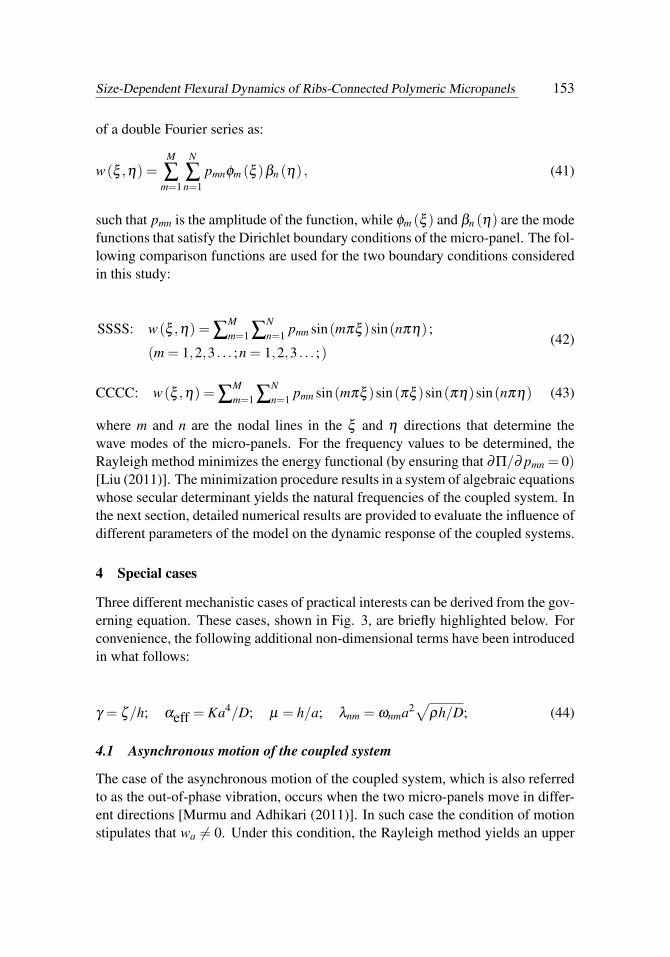
of a double Fourier series as:
w(ξ ,η) =M
∑m=1
N
∑n=1
pmnφm (ξ )βn (η) , (41)
such that pmn is the amplitude of the function, while φm (ξ ) and βn (η) are the modefunctions that satisfy the Dirichlet boundary conditions of the micro-panel. The fol-lowing comparison functions are used for the two boundary conditions consideredin this study:
SSSS: w(ξ ,η) = ∑Mm=1 ∑
Nn=1 pmn sin(mπξ )sin(nπη) ;
(m = 1,2,3 . . . ;n = 1,2,3 . . . ;)(42)
CCCC: w(ξ ,η) = ∑Mm=1 ∑
Nn=1 pmn sin(mπξ )sin(πξ )sin(πη)sin(nπη) (43)
where m and n are the nodal lines in the ξ and η directions that determine thewave modes of the micro-panels. For the frequency values to be determined, theRayleigh method minimizes the energy functional (by ensuring that ∂Π/∂ pmn = 0)[Liu (2011)]. The minimization procedure results in a system of algebraic equationswhose secular determinant yields the natural frequencies of the coupled system. Inthe next section, detailed numerical results are provided to evaluate the influence ofdifferent parameters of the model on the dynamic response of the coupled systems.
4 Special cases
Three different mechanistic cases of practical interests can be derived from the gov-erning equation. These cases, shown in Fig. 3, are briefly highlighted below. Forconvenience, the following additional non-dimensional terms have been introducedin what follows:
γ = ζ/h; αeff = Ka4/D; µ = h/a; λnm = ωnma2√
ρh/D; (44)
4.1 Asynchronous motion of the coupled system
The case of the asynchronous motion of the coupled system, which is also referredto as the out-of-phase vibration, occurs when the two micro-panels move in differ-ent directions [Murmu and Adhikari (2011)]. In such case the condition of motionstipulates that wa 6= 0. Under this condition, the Rayleigh method yields an upper

154 Copyright © 2014 Tech Science Press CMC, vol.42, no.2, pp.141-174, 2014
estimate of the frequency of the coupled micro-panels with the SSSS edge condi-tions as:
(λnm)2 =[
12γ2(−6m4π4+6m4π4v−12m2n2π4φ 2+12m2n2π4vφ 2−6n4π4φ 4 +6n4π4vφ 4
)12+µ2φ +µ2φ 3
+12(m4π4 +2m2n2π4φ 2 +n4π4φ 4 +2αe f f
)12+µ2φ +µ2φ 3
].
(45)
In Eq. (45), γ now represents the influence of the size-effect (that is, the mate-rial length scale of the micro-panel). This specific parameter quantifies the size-dependent vibration dynamics of the micro-panel with respect to the micro-panel’sthickness. Also, αe f f is the non-dimensional averaged stiffness of the elastic con-nections, while µ and φ represent the thickness-to-length ratio and the aspect ratioof the micro-panel, respectively
4.2 Synchronous motion of the coupled system
Under a synchronous motion, the movements of the two micro-panels are in sync.Hence, this case is also referred to as the in-phase vibration Here, the condition ofmotion during the in-phase vibration requires that wa = 0. With this, the Rayleighmethod again yields an upper estimate of the frequency of the coupled micro-panelswith SSSS edge conditions as:
(λnm)2 =[
12(m4π4 +2m2n2π4φ 2 +n4π4φ 4
)12+µ2φ +µ2φ 3
+12γ2
(−6m4π4 +6m4π4v−12m2n2π4φ 2 +12m2n2π4vφ 2−6n4π4vφ 4
)12+µ2φ +µ2φ 3
].
(46)
4.3 Motion of the upper-panel supported by the ribs
The third special case relates to the situation when the lower micro-panel is a rigidbase. Such situations do arise in the development of a mass sensing device [Agache,Blanco-Gomez, Cochet and Caillat (2011)]. When this occurs, then wl = 0. Con-sequently, the frequency of the remnant systems is governed by the geometric andmaterial properties as well as the boundary conditions of the upper micro-panel and
Size-Dependent Flexural Dynamics of Ribs-Connected Polymeric Micropanels 155
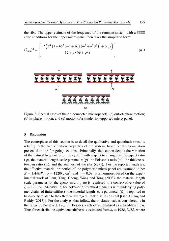
the ribs. The upper estimate of the frequency of the remnant system with a SSSSedge conditions for the upper micro-panel then takes the simplified form:
(λnm)2 =
12(
π4(1+6γ2 (−1+υ)
)(m2 +n2ϕ2
)2+αe f f
)12+µ2 (ϕ +ϕ3)
(47)
Figure 3: Special cases of the rib-connected micro-panels: (a) out-of-phase motion;(b) in-phase motion; and (c) motion of a single rib-supported micro-panel.
5 Discussion
The centerpiece of this section is to detail the qualitative and quantitative resultsrelating to the free vibration properties of the system, based on the formulationpresented in the foregoing sections. Principally, the section details the variationof the natural frequencies of the system with respect to changes in the aspect ratio(ϕ), the material length scale parameter (γ), the Poisson’s ratio (ν), the thickness-to-span ratio (µ), and the stiffness of the ribs (αe f f ). For the reported analyses,the effective material properties of the polymeric micro-panel are assumed to be:E = 1.44GPa; ρ = 1220kg/m3; and ν = 0.38. Furthermore, based on the exper-imental work of Lam, Yang, Chong, Wang and Tong (2003), the material lengthscale parameter for the epoxy micro-plate is restricted to a conservative value ofζ = 17.6µm. Meanwhile, for polymeric structural elements with underlying poly-mer chains of finite stiffness, the material length scale parameter (ζ ) is reported tobe directly related to the effective averaged Frank elastic constant [Gao, Huang andReddy (2013)]. For the analyses that follow, the thickness values considered is inthe range 20µm ≤ h ≤ 176µm. Besides, each rib is idealized as a fixed-fixed bar.Thus for each rib, the equivalent stiffness is estimated from kr = 192ErIr/L3
r , where
156 Copyright © 2014 Tech Science Press CMC, vol.42, no.2, pp.141-174, 2014
Ar, Ir,Er, and Lr are the cross-sectional area, the moment of inertia, the Young’smodulus and length of each rib.
5.1 Validation
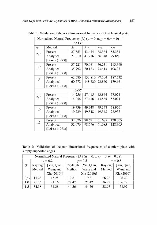
For the purpose of validation, the governing equation of the system is modifiedby eliminating the parameters µ , αe f f and γ from the mathematical model. Withthis elimination, the governing equation is reduced to that of the Kirchhoff’s platetheory [Szilard (2004)]. Tab. 1 reveals the comparison of the frequency values,based on the reduced form of the current model, with the classic work of Leissa(1973). Tab. 1 contains selected numerical results for a panel (treated as a plate)under the SSSS edge conditions and the CCCC edge conditions.
Tab. 2 provides the validation of the non-dimensional frequencies of a micro-platewith simply-supported edges. The governing equation employed for the results inTab. 2 contains γ , but it does not contain αe f f and µ . The validation involvescomparison with the closed-form expression presented in Yin, Qian, Wang and Xia(2010). It is noticed from Tab. 2 that a good agreement is achieved between thepredicted non-dimensional frequency from the current method and the closed-formsolution.
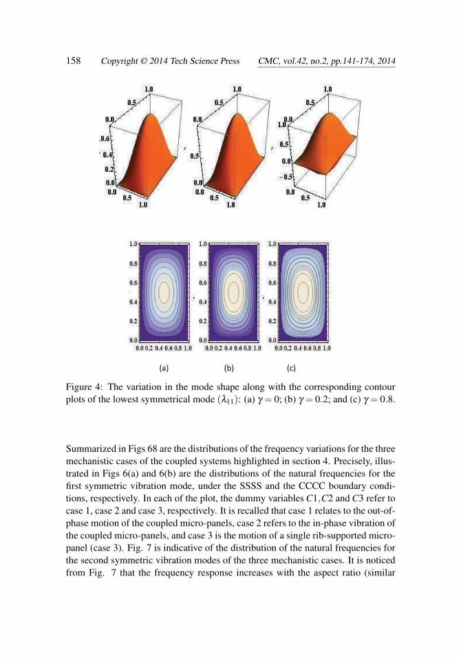
For brevity sake, the discussion is restricted to the two lowest symmetrical modesof the flexural vibration (whose non-dimensional frequency parameters are λ11 andλ22) in the next subsections. For completeness, the mode shapes correspondingto both λ11 and λ22 are shown in Figs 4 and 5, respectively. In these figures, thecontour plot corresponding to each of the two vibration modes are also providedunder each of the mode shape. From the plots, it is noticed that increasing valuesof the small-scale parameter stiffen the response of the micro-panel. Besides, asseen from the contour plots, higher values of the small-scale parameter generatemore equilibrium positions during the deformation of the system.
5.2 Frequency distribution and frequency shift
To evaluate the frequency shift induced by the small-scale parameter, a percentagechange in the computed natural frequencies based on the MCST and the classical(size-independent) theory is defined as:
Rnm =
∣∣∣∣(λnm)CCT − (λnm)MCST(λnm)CCT
∣∣∣∣×100 (48)
where (λnm)MCST is the natural frequency of the system from the MCST, while(λnm)CCT is the corresponding natural frequency from the CCT. Besides, λnm is thenon-dimensional natural frequency parameter defined as:
λnm = ωnma2√
ρh/D. (49)
Size-Dependent Flexural Dynamics of Ribs-Connected Polymeric Micropanels 157
Table 1: Validation of the non-dimensional frequencies of a classical plate.
Normalized Natural Frequency (λ ) (µ = 0,αe f f = 0,γ = 0)CCCC
ϕ Method λ11 λ12 λ21 λ22
2/3Present 27.853 43.424 68.364 83.351Analytical[Leissa (1973)]
27.010 41.716 66.148 79.850
1.0Present 37.221 70.081 76.231 113.390Analytical[Leissa (1973)]
35.992 70.123 73.413 108.27
1.5Present 62.680 153.810 97.704 187.532Analytical[Leissa (1973)]
60.772 148.820 93.860 179.66
SSSS
2/3Present 14.256 27.415 43.864 57.024Analytical[Leissa (1973)]
14.256 27.416 43.865 57.024
1.0Present 19.739 49.348 49.348 78.956Analytical[Leissa (1973)]
19.739 49.348 49.348 78.957
1.5Present 32.076 98.69 61.685 128.305Analytical[Leissa (1973)]
32.076 98.696 61.685 128.305
Table 2: Validation of the non-dimensional frequencies of a micro-plate withsimply-supported edges.
Normalized Natural Frequency (λ ) (µ = 0,αe f f = 0,υ = 0.38)γ = 0.2 γ = 0.5 γ = 0.8
ϕ RayleighMethod
[Yin, Qian,Wang and
Xia (2010)]
RayleighMethod
[Yin, Qian,Wang and
Xia (2010)]
RayleighMethod
[Yin, Qian,Wang and
Xia (2010)]2/3 15.28 15.28 19.81 19.81 26.22 26.221.0 21.16 21.16 27.42 27.42 36.29 36.291.5 34.38 34.38 44.56 44.56 58.97 58.97
158 Copyright © 2014 Tech Science Press CMC, vol.42, no.2, pp.141-174, 2014
(a) (b) (c)
Figure 4: The variation in the mode shape along with the corresponding contourplots of the lowest symmetrical mode (λ11): (a) γ = 0; (b) γ = 0.2; and (c) γ = 0.8.
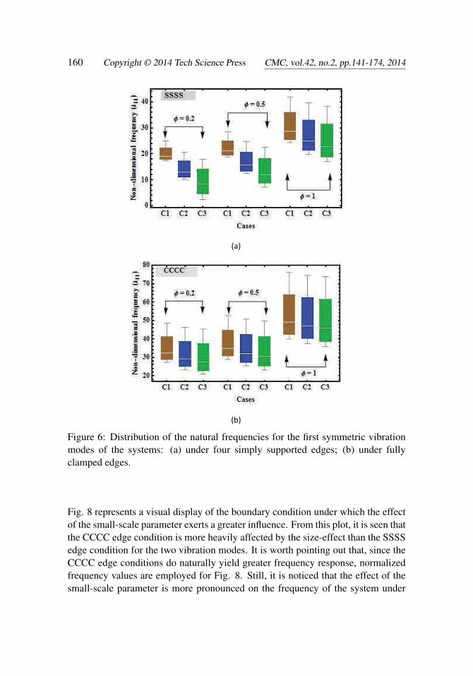
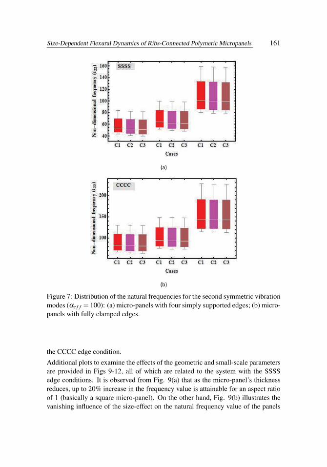
Summarized in Figs 68 are the distributions of the frequency variations for the threemechanistic cases of the coupled systems highlighted in section 4. Precisely, illus-trated in Figs 6(a) and 6(b) are the distributions of the natural frequencies for thefirst symmetric vibration mode, under the SSSS and the CCCC boundary condi-tions, respectively. In each of the plot, the dummy variables C1,C2 and C3 refer tocase 1, case 2 and case 3, respectively. It is recalled that case 1 relates to the out-of-phase motion of the coupled micro-panels, case 2 refers to the in-phase vibration ofthe coupled micro-panels, and case 3 is the motion of a single rib-supported micro-panel (case 3). Fig. 7 is indicative of the distribution of the natural frequencies forthe second symmetric vibration modes of the three mechanistic cases. It is noticedfrom Fig. 7 that the frequency response increases with the aspect ratio (similar
Size-Dependent Flexural Dynamics of Ribs-Connected Polymeric Micropanels 159
(a) (b) (c)
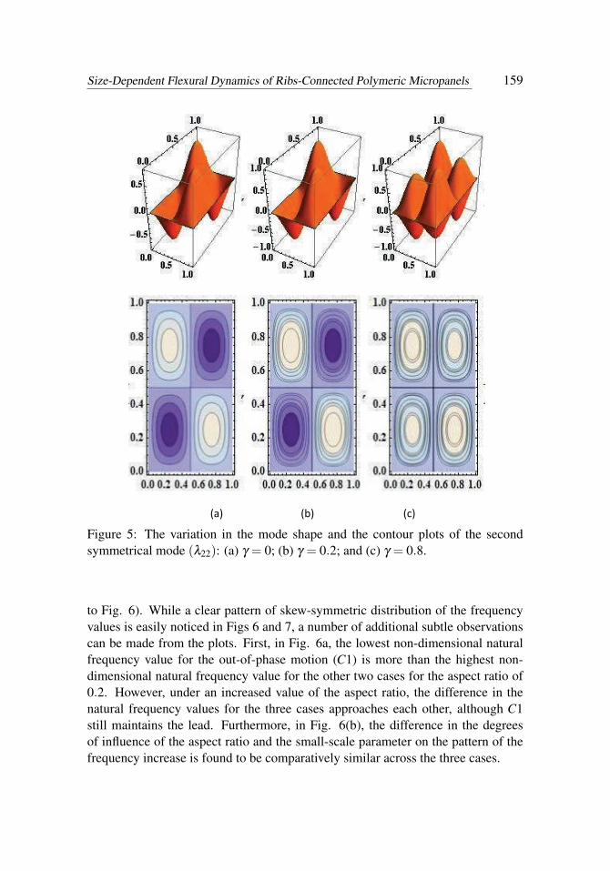
Figure 5: The variation in the mode shape and the contour plots of the secondsymmetrical mode (λ22): (a) γ = 0; (b) γ = 0.2; and (c) γ = 0.8.
to Fig. 6). While a clear pattern of skew-symmetric distribution of the frequencyvalues is easily noticed in Figs 6 and 7, a number of additional subtle observationscan be made from the plots. First, in Fig. 6a, the lowest non-dimensional naturalfrequency value for the out-of-phase motion (C1) is more than the highest non-dimensional natural frequency value for the other two cases for the aspect ratio of0.2. However, under an increased value of the aspect ratio, the difference in thenatural frequency values for the three cases approaches each other, although C1still maintains the lead. Furthermore, in Fig. 6(b), the difference in the degreesof influence of the aspect ratio and the small-scale parameter on the pattern of thefrequency increase is found to be comparatively similar across the three cases.
160 Copyright © 2014 Tech Science Press CMC, vol.42, no.2, pp.141-174, 2014
(a)
(b)
Figure 6: Distribution of the natural frequencies for the first symmetric vibrationmodes of the systems: (a) under four simply supported edges; (b) under fullyclamped edges.
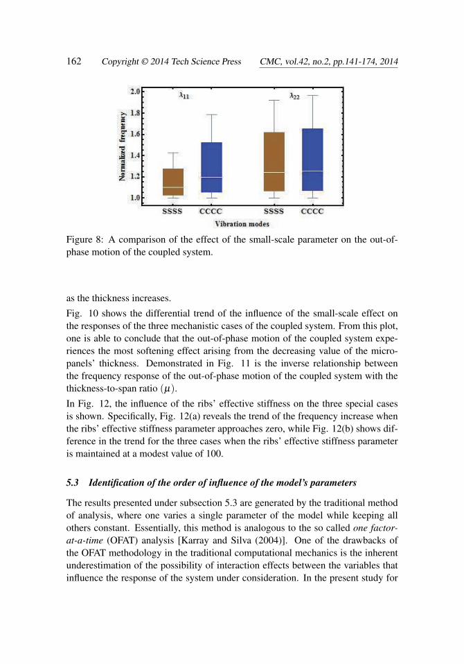
Fig. 8 represents a visual display of the boundary condition under which the effectof the small-scale parameter exerts a greater influence. From this plot, it is seen thatthe CCCC edge condition is more heavily affected by the size-effect than the SSSSedge condition for the two vibration modes. It is worth pointing out that, since theCCCC edge conditions do naturally yield greater frequency response, normalizedfrequency values are employed for Fig. 8. Still, it is noticed that the effect of thesmall-scale parameter is more pronounced on the frequency of the system under
Size-Dependent Flexural Dynamics of Ribs-Connected Polymeric Micropanels 161
(a)
(b)
Figure 7: Distribution of the natural frequencies for the second symmetric vibrationmodes (αe f f = 100): (a) micro-panels with four simply supported edges; (b) micro-panels with fully clamped edges.
the CCCC edge condition.
Additional plots to examine the effects of the geometric and small-scale parametersare provided in Figs 9-12, all of which are related to the system with the SSSSedge conditions. It is observed from Fig. 9(a) that as the micro-panel’s thicknessreduces, up to 20% increase in the frequency value is attainable for an aspect ratioof 1 (basically a square micro-panel). On the other hand, Fig. 9(b) illustrates thevanishing influence of the size-effect on the natural frequency value of the panels
162 Copyright © 2014 Tech Science Press CMC, vol.42, no.2, pp.141-174, 2014
Figure 8: A comparison of the effect of the small-scale parameter on the out-of-phase motion of the coupled system.
as the thickness increases.
Fig. 10 shows the differential trend of the influence of the small-scale effect onthe responses of the three mechanistic cases of the coupled system. From this plot,one is able to conclude that the out-of-phase motion of the coupled system expe-riences the most softening effect arising from the decreasing value of the micro-panels’ thickness. Demonstrated in Fig. 11 is the inverse relationship betweenthe frequency response of the out-of-phase motion of the coupled system with thethickness-to-span ratio (µ).
In Fig. 12, the influence of the ribs’ effective stiffness on the three special casesis shown. Specifically, Fig. 12(a) reveals the trend of the frequency increase whenthe ribs’ effective stiffness parameter approaches zero, while Fig. 12(b) shows dif-ference in the trend for the three cases when the ribs’ effective stiffness parameteris maintained at a modest value of 100.
5.3 Identification of the order of influence of the model’s parameters
The results presented under subsection 5.3 are generated by the traditional methodof analysis, where one varies a single parameter of the model while keeping allothers constant. Essentially, this method is analogous to the so called one factor-at-a-time (OFAT) analysis [Karray and Silva (2004)]. One of the drawbacks ofthe OFAT methodology in the traditional computational mechanics is the inherentunderestimation of the possibility of interaction effects between the variables thatinfluence the response of the system under consideration. In the present study for

Size-Dependent Flexural Dynamics of Ribs-Connected Polymeric Micropanels 163
(a)
(b)
Figure 9: The quantification of the percentage change in frequency values: (a)the change in frequency against the small-scale effect; (b) the change in frequencyagainst the micro-panels’ thickness.
instance, we recognized five continuous numerical dimensionless parameters thatcould influence the response of the system as seen in Fig. 13. These five continuousnumerical parameters (or factors) are the aspect ratio (ϕ), the small-scale parameter(γ), the ribs’ effective stiffness (αe f f ), the Poisson’s ratio (ν) and the thickness-to-span ratio (µ). In what follows, the OFAT analysis is complemented with theapplied statistical method of design of experiment (DOE) [Dean and Voss (1999);Mustapha and Zhong (2012)] to examine the order of influence of these parameters.
Figs. 14-16 are indicative of the outcome of the analyses based on the use of theDOE. Two levels of each of the five parameters are considered for the numerical

164 Copyright © 2014 Tech Science Press CMC, vol.42, no.2, pp.141-174, 2014
Figure 10: Variation of frequency values with varying value of the material lengthscale for the special motion types of the system.
Figure 11: The effect of rotary inertia on the two lowest symmetric vibration modesfor the out-of-phase motion of the coupled system.
DOE. Based on the established procedure of DOE, an experimental design involv-ing five input factors at two levels (low and high) becomes a problem of 2p numberof experimental runs, where the superscript p is the number of factors. The capa-bility of the statistical software Minitab [Lesik (2010)] is used to run a randomizeddesign of the experiment. It is pointed out that the term experiment is used in thesense of numerical analysis experiment in the current setting. The values of thefactors at each run of the experiment are presented in Tab. 3.
The ordered ranking of the model’s factors (also refers to as main effects) as theyinfluence the response of the system are presented in the form of the Pareto chartsdepicted in Figs 14-16. In these charts the terms A,B,C,D and E are dummy vari-ables that symbolize the ribs effective stiffness, the aspect ratio, the size-effect, thethickness-to-span ratio and the Poisson’s ratio, respectively. The combinations of

Size-Dependent Flexural Dynamics of Ribs-Connected Polymeric Micropanels 165
(a)
(b)
Figure 12: The effect of the ribs’ stiffness on the three special cases: (a) a negligibleribs’ effective stiffness parameter; (b) ribs’ effective stiffness maintained at 100.
Figure 13: The relation between the inputs and the output of the coupled micro-panels system.

166 Copyright © 2014 Tech Science Press CMC, vol.42, no.2, pp.141-174, 2014
these dummy variables (such as AB,ACandABC etc.,) are visible in these charts,and they are called the interaction effects. Specifically, Figs. 14, 15 and 16 repre-sent the Pareto chart of case 1 (the asynchronous motion), case 2 (the synchronousmotion) and case 3 (the motion of a rib-connected micro-panel), respectively.
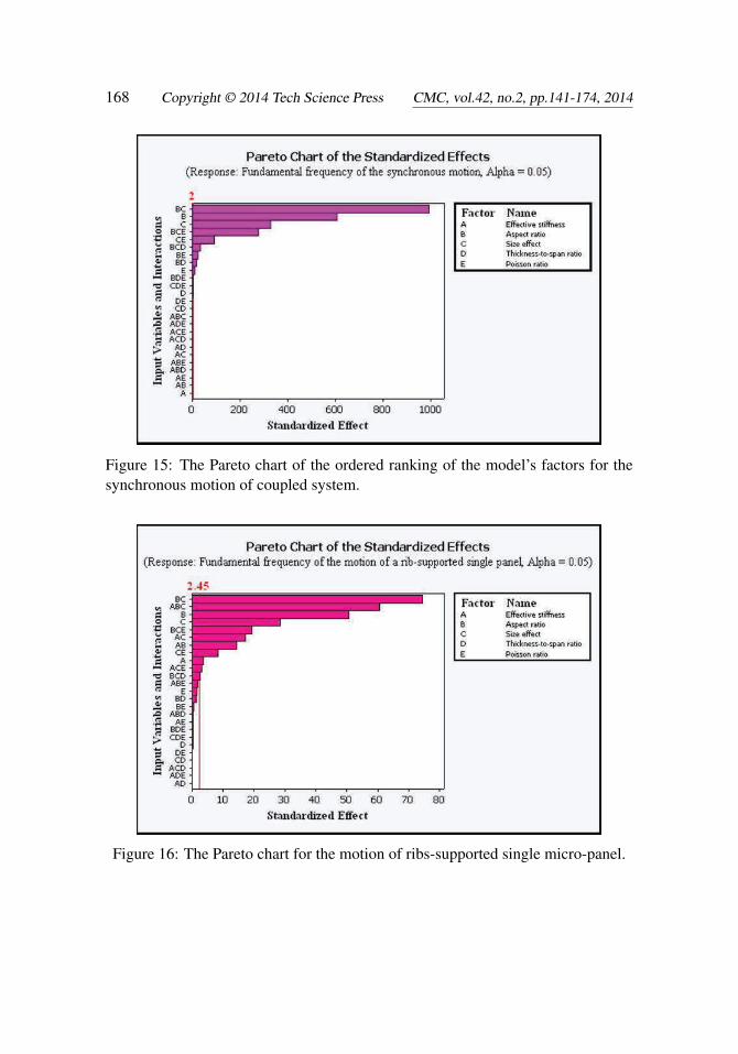
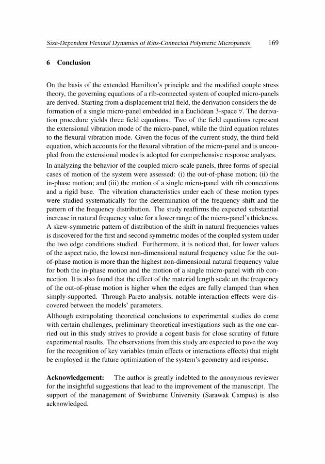
It is observed from Figs 14-16 that the factor that affects the natural frequency ofthe motion of the three cases the most is the interaction factor BC.This interactionfactor is created by the interaction between the aspect ratio and the size-effect pa-rameter. Furthermore, it is observed from the Pareto charts that the Poisson’s ratiohas a somewhat negligible effect on the motion of the three systems. However,the interaction effect created between the Poisson’s ratio, the aspect ratio and size-effect (BCE) is the fourth most significant factor that influences the behavior ofthe synchronous motion. An additional conclusion that can be drawn from thesecharts is the fact the size-effect is the second most significant factor that alters thenatural frequency of the system for case 1 and case 2. It is also the third most sig-nificant factor for case 3. Besides, the thickness-to-span ratio is discovered not tosignificantly affect the response of any of the three mechanistic cases.
Figure 14: The Pareto chart of the ordered ranking of the model’s factors for theasynchronous motion of coupled system.

Size-Dependent Flexural Dynamics of Ribs-Connected Polymeric Micropanels 167
Table 3: Randomized numerical experimental runs.
Continuous input variables Response (λ11)Case 1 Case 2 Case 3
1 10 1.5 0.8 0.05 0.25 63.308 63.150 63.0712 200 0.1 0.8 0.25 0.38 27.121 18.323 11.6563 200 0.1 0.8 0.25 0.25 28.020 19.630 13.6174 200 0.1 0.1 0.25 0.25 22.440 10.187 9.8035 10 1.5 0.1 0.25 0.25 32.681 32.381 32.2306 10 1.5 0.1 0.05 0.38 32.955 32.650 32.4977 10 0.1 0.1 0.25 0.25 11.125 10.187 9.6848 10 1.5 0.1 0.05 0.25 33.076 32.773 32.6209 10 0.1 0.1 0.25 0.38 11.090 10.149 9.64410 10 0.1 0.8 0.05 0.25 20.137 19.635 19.37811 10 0.1 0.8 0.25 0.38 18.861 18.323 18.04912 200 1.5 0.8 0.25 0.38 61.501 58.243 56.54413 10 1.5 0.1 0.25 0.38 32.561 32.260 32.10814 200 1.5 0.1 0.25 0.25 37.929 32.381 29.21415 200 0.1 0.1 0.25 0.38 22.423 10.149 9.84316 10 0.1 0.8 0.25 0.25 20.132 19.630 19.37317 10 0.1 0.1 0.05 0.38 11.093 10.151 9.64618 200 1.5 0.1 0.05 0.38 38.284 32.650 29.43219 200 0.1 0.8 0.05 0.25 28.027 19.635 13.62120 10 0.1 0.1 0.05 0.25 11.128 10.190 9.68621 200 1.5 0.8 0.25 0.25 65.440 62.395 60.81222 200 1.5 0.8 .. 0.38 62.245 58.948 57.22823 200 1.5 0.1 0.05 0.25 38.388 32.773 29.56824 200 1.5 0.1 0.25 0.38 37.826 32.260 29.08025 10 1.5 0.8 0.05 0.38 59.117 58.948 58.86326 10 0.1 0.8 0.05 0.38 18.866 18.328 18.05327 10 1.5 0.8 0.25 0.38 58.410 58.243 58.15928 200 0.1 0.1 0.05 0.25 22.446 10.190 9.80629 200 1.5 0.8 0.05 0.25 66.239 63.150 61.54830 10 1.5 0.8 0.25 0.25 62.551 62.395 62.31731 200 0.1 0.8 0.05 0.38 27.127 18.328 11.65932 200 0.1 0.1 0.05 0.38 22.428 10.151 9.846
168 Copyright © 2014 Tech Science Press CMC, vol.42, no.2, pp.141-174, 2014
Figure 15: The Pareto chart of the ordered ranking of the model’s factors for thesynchronous motion of coupled system.
Figure 16: The Pareto chart for the motion of ribs-supported single micro-panel.
Size-Dependent Flexural Dynamics of Ribs-Connected Polymeric Micropanels 169
6 Conclusion
On the basis of the extended Hamilton’s principle and the modified couple stresstheory, the governing equations of a rib-connected system of coupled micro-panelsare derived. Starting from a displacement trial field, the derivation considers the de-formation of a single micro-panel embedded in a Euclidean 3-space ∀. The deriva-tion procedure yields three field equations. Two of the field equations representthe extensional vibration mode of the micro-panel, while the third equation relatesto the flexural vibration mode. Given the focus of the current study, the third fieldequation, which accounts for the flexural vibration of the micro-panel and is uncou-pled from the extensional modes is adopted for comprehensive response analyses.
In analyzing the behavior of the coupled micro-scale panels, three forms of specialcases of motion of the system were assessed: (i) the out-of-phase motion; (ii) thein-phase motion; and (iii) the motion of a single micro-panel with rib connectionsand a rigid base. The vibration characteristics under each of these motion typeswere studied systematically for the determination of the frequency shift and thepattern of the frequency distribution. The study reaffirms the expected substantialincrease in natural frequency value for a lower range of the micro-panel’s thickness.A skew-symmetric pattern of distribution of the shift in natural frequencies valuesis discovered for the first and second symmetric modes of the coupled system underthe two edge conditions studied. Furthermore, it is noticed that, for lower valuesof the aspect ratio, the lowest non-dimensional natural frequency value for the out-of-phase motion is more than the highest non-dimensional natural frequency valuefor both the in-phase motion and the motion of a single micro-panel with rib con-nection. It is also found that the effect of the material length scale on the frequencyof the out-of-phase motion is higher when the edges are fully clamped than whensimply-supported. Through Pareto analysis, notable interaction effects were dis-covered between the models’ parameters.
Although extrapolating theoretical conclusions to experimental studies do comewith certain challenges, preliminary theoretical investigations such as the one car-ried out in this study strives to provide a cogent basis for close scrutiny of futureexperimental results. The observations from this study are expected to pave the wayfor the recognition of key variables (main effects or interactions effects) that mightbe employed in the future optimization of the system’s geometry and response.
Acknowledgement: The author is greatly indebted to the anonymous reviewerfor the insightful suggestions that lead to the improvement of the manuscript. Thesupport of the management of Swinburne University (Sarawak Campus) is alsoacknowledged.

170 Copyright © 2014 Tech Science Press CMC, vol.42, no.2, pp.141-174, 2014
References
Agache, V.; Blanco-Gomez, G.; Cochet, M.; Caillat, P. (2011): Suspendednanochannel in MEMS plate resonator for mass sensing in liquid. Micro ElectroMechanical Systems (MEMS), 2011 IEEE 24th International Conference on.
Aifantis, E. C. (1992): On the role of gradients in the localization of deformationand fracture. International Journal of Engineering Science, vol. 30, no. 10, pp.1279-1299.
Aifantis, E. C. (2011): On the gradient approach – Relation to Eringen’s nonlocaltheory. International Journal of Engineering Science, vol. 49, no. 12, pp. 1367-1377.
Akgöz, B.; Civalek, Ö. (2013): Free vibration analysis of axially functionallygraded tapered Bernoulli-Euler microbeams based on the modified couple stresstheory. Composite Structures, vol. 98, pp. 314-322.
Akgöz, B.; Civalek, Ö. (2013): Modeling and analysis of micro-sized plates rest-ing on elastic medium using the modified couple stress theory. Meccanica, vol. 48,no. 4, pp. 863-873.
Anthoine, A. (2000): Effect of couple-stresses on the elastic bending of beams.International Journal of Solids and Structures, vol. 37, no. 7, pp. 1003-1018.
Ardito, R.; Baldasarre, L.; Corigliano, A.; De Masi, B.; Frangi, A.; Magagnin,L. (2013): Experimental evaluation and numerical modeling of adhesion phenom-ena in polysilicon MEMS. Meccanica, vol. 48, no. 8, pp. 1835-1844.
Benkhelifa, E.; Farnsworth, M.; Tiwari, A.; Bandi, G. (2010): Design andoptimisation of microelectromechanical systems: a review of the state-of-the-art.International Journal of Design Engineering, vol. 3, no. 1, pp. 41-76.
Boisen, A.; Dohn, S.; Keller, S. S.; Schmid, S.; Tenje, M. (2011): Cantilever-likemicromechanical sensors. Reports on Progress in Physics, vol. 74, no. 3.
Chiroiu, V.; Munteanu, L.; Delsanto, P. P. (2010): Evaluation of the Toupin-Mindlin theory for predicting the size effects in the buckling of the carbon nan-otubes. Computers, Materials & Continua (CMC), vol. 16, no. 2, pp. 75.
Chiroiu, V.; Munteanu, L.; Gliozzi, A. S. (2010): Application of Cosserat Theoryto the Modelling of Reinforced Carbon Nananotube Beams. Computers Materialsand Continua, vol. 19, no. 1, pp. 1.
Cosserat, E.; Cosserat, F. (1909): Théorie des Corps Déformables. A. Hermannet Fils, Paris.
Dean, A. M.; Voss, D. (1999): Design and analysis of experiments, Springer.
Eringen, A. C. (1972): Nonlocal polar elastic continua. International Journal of

Size-Dependent Flexural Dynamics of Ribs-Connected Polymeric Micropanels 171
Engineering Science, vol. 10, no. 1, pp. 1-16.
Eringen, A. C.; Edelen, D. G. B. (1972): On nonlocal elasticity. InternationalJournal of Engineering Science, vol. 10, no. 3, pp. 233-248.
Farokhi, H.; Ghayesh, M. H.; Amabili, M. (2013): Nonlinear dynamics of ageometrically imperfect microbeam based on the modified couple stress theory.International Journal of Engineering Science, vol. 68, pp. 11-23.
Fleck, N. A.; Hutchinson, J. W. (1993): A phenomenological theory for straingradient effects in plasticity. Journal of the Mechanics and Physics of Solids, vol.41, no. 12, pp. 1825-1857.
Fotouhi, M. M.; Firouz-Abadi, R. D.; Haddadpour, H. (2013): Free vibrationanalysis of nanocones embedded in an elastic medium using a nonlocal continuumshell model. International Journal of Engineering Science, vol. 64, pp. 14-22.
Gao, X. L.; Huang, J. X.; Reddy, J. N. (2013): A non-classical third-order sheardeformation plate model based on a modified couple stress theory. Acta Mechanica,vol. 224, no. 11, pp. 2699-2718.
Georgiadis, H. G.; Velgaki, E. G. (2003): High-frequency Rayleigh waves inmaterials with micro-structure and couple-stress effects. International Journal ofSolids and Structures, vol. 40, no. 10, pp. 2501-2520.
Güven, U. (2011): The investigation of the nonlocal longitudinal stress waves withmodified couple stress theory. Acta Mechanica, vol. 221, no. 3-4, pp. 321-325.
Jomehzadeh, E.; Noori, H. R.; Saidi, A. R. (2011): The size-dependent vibrationanalysis of micro-plates based on a modified couple stress theory. Physica E: Low-dimensional Systems and Nanostructures, vol. 43, no. 4, pp. 877-883.
Karray, F.; Silva, C. D. (2004): Soft Computing and Tools of Intelligent SystemsDesign: Theory and Applications.
Kun, W.; Nguyen, C. T. C. (1999): High-order medium frequency micromechan-ical electronic filters. Microelectromechanical Systems, Journal of, vol. 8, no. 4,pp. 534-556.
Lam, D. C. C.; Yang, F.; Chong, A. C. M.; Wang, J.; Tong, P. (2003): Experi-ments and theory in strain gradient elasticity. Journal of the Mechanics and Physicsof Solids, vol. 51, no. 8, pp. 1477-1508.
Leissa, A. W. (1973): The free vibration of rectangular plates. Journal of Soundand Vibration, vol. 31, no. 3, pp. 257-293.
Lesik, S. A. (2010): Applied Statistical Inference with MINITAB, CRC Press.
Liew, K. M.; Wong, C. H.; He, X. Q.; Tan, M. J.; Meguid, S. A. (2004):Nanomechanics of single and multiwalled carbon nanotubes. Physical Review B

172 Copyright © 2014 Tech Science Press CMC, vol.42, no.2, pp.141-174, 2014
- Condensed Matter and Materials Physics, vol. 69, no. 11, pp. 1154291-1154298.
Liu, D.-S.; Tu, C.-Y.; Chung, C.-L. (2012): Eigenvalue Analysis of MEMS Com-ponents with Multi-defect using Infinite Element Method Algorithm. ComputersMaterials and Continua, vol. 28, no. 2, pp. 97.
Liu, M. (2011): Orthogonal Tapered Beam Functions in the Study of Free Vi-brations for Non-uniform Isotropic Rectangular Plates. Computers Materials andContinua, vol. 22, no. 2, pp. 97.
Mahdavi, M. H.; Farshidianfar, A.; Tahani, M.; Mahdavi, S.; Dalir, H. (2008):A more comprehensive modeling of atomic force microscope cantilever. Ultrami-croscopy, vol. 109, no. 1, pp. 54-60.
Manzaneque, T.; Ruiz, V.; Hernando-Garcia, J.; Ababneh, A.; Seidel, H.;Sanchez-Rojas, J. L. (2012): Characterization and simulation of the first exten-sional mode of rectangular micro-plates in liquid media. Applied Physics Letters101(15): 151904-151904-151904.
Marin, M.; Agarwal, R. P.; Othman, M. (2014): Localization in Time of Solu-tions for Thermoelastic Micropolar Materials with Voids. CMC: Computers, Ma-terials & Continua, vol. 40, no. 1, pp. 35-48.
Mattila, T.; Kiihamäki, J.; Lamminmäki, T.; Jaakkola, O.; Rantakari, P.; Oja,A.; Seppä, H.; Kattelus, H.; Tittonen, I. (2002): A 12 MHz micromechanicalbulk acoustic mode oscillator. Sensors and Actuators A: Physical, vol. 101,no.1–2, pp. 1-9.
Murmu, T.; Adhikari, S. (2011): Nonlocal vibration of bonded double-nanoplate-systems. Composites Part B: Engineering, vol. 42, no. 7, pp. 1901-1911.
Mustapha, K. B. (2014): Modeling of a functionally graded micro-ring segmentfor the analysis of coupled extensional–flexural waves. Composite Structures, vol.117, pp. 274-287.
Mustapha, K. B.; Zhong, Z. W. (2012): A new modeling approach for the dy-namics of a micro end mill in high-speed micro-cutting. Journal of Vibration andControl.
Mustapha, K. B.; Zhong, Z. W. (2012): Spectral element analysis of a non-classical model of a spinning micro beam embedded in an elastic medium. Mecha-nism and Machine Theory, vol. 53, pp. 66-85.
Mustapha, K. B.; Z. W. Zhong (2012): Wave propagation characteristics of atwisted micro scale beam. International Journal of Engineering Science, vol. 53,pp. 46-57.
Nguyen, C. T. C. (1995): Micromechanical resonators for oscillators and filters.Ultrasonics Symposium, 1995. Proceedings., 1995 IEEE.
Size-Dependent Flexural Dynamics of Ribs-Connected Polymeric Micropanels 173
Papacharalampopoulos, A.; Karlis, G.; Charalambopoulos, A.; Polyzos, D.(2010): BEM Solutions for 2 D and 3 D Dynamic Problems in Mindlin’s StrainGradient Theory of Elasticity. Computer Modeling in Engineering & Sciences(CMES),vol. 58, no. 1, pp. 45-74.
Papargyri-Beskou, S.; Tsepoura, K. G.; Polyzos, D.; Beskos, D. E. (2003):Bending and stability analysis of gradient elastic beams. International Journalof Solids and Structures, vol. 40, no. 2, pp. 385-400.
Park, S. K.; Gao, X. L. (2006): Bernoulli-Euler beam model based on a modifiedcouple stress theory. Journal of Micromechanics and Microengineering, vol. 16,no. 11, pp. 2355-2359.
Peddieson, J.; Buchanan, G. R.; McNitt, R. P. (2003): Application of nonlo-cal continuum models to nanotechnology. International Journal of EngineeringScience, vol. 41, no. 3-5, pp. 305-312.
Reddy, J. N. (2002): Energy principles and variational methods in applied me-chanics. Hoboken, N.J., Wiley.
Reddy, J. N. (2011): Microstructure-dependent couple stress theories of function-ally graded beams. Journal of the Mechanics and Physics of Solids, vol. 59, no.11, pp. 2382-2399.
Romanoff, J.; Reddy, J. (2014): Experimental validation of the modified couplestress Timoshenko beam theory for web-core sandwich panels. Composite Struc-tures, vol. 111, pp. 130-137.
Sakhaee-Pour, A.; Ahmadian, M.; Vafai, A. (2008): Applications of single-layered graphene sheets as mass sensors and atomistic dust detectors. Solid StateCommunications, vol. 145, no. 4, pp. 168-172.
Szilard, R. (2004): Theories and applications of plate analysis : classical, numer-ical, and engineering methods. Hoboken, N.J., John Wiley.
Tang, Z.; Shen, S.; Atluri, S. (2003): Analysis of materials with strain-gradienteffects: A meshless local Petrov-Galerkin (MLPG) approach, with nodal displace-ments only. Computer Modeling in Engineering and Sciences, vol. 4, no, 1, pp.177-196.
Toupin, R. A. (1962): Elastic materials with couple-stresses. Archive for RationalMechanics and Analysis, vol. 11, no. 1, pp. 385-414.
Uchic, M. D.; Dimiduk, D. M.; Florando, J. N.; Nix, W. D. (2004): Sampledimensions influence strength and crystal plasticity. Science, vol. 305, no. 5686,pp. 986-989.
Volkert, C. A.; Lilleodden, E. T. (2006): Size effects in the deformation of sub-micron Au columns. Philosophical Magazine, vol. 86, no. 33-35, pp. 5567-5579.
174 Copyright © 2014 Tech Science Press CMC, vol.42, no.2, pp.141-174, 2014
Wang, L.; Liu, H. T.; Ni, Q.; Wu, Y. (2013): Flexural vibrations of microscalepipes conveying fluid by considering the size effects of micro-flow and micro-structure. International Journal of Engineering Science, vol. 71, no. 0, pp. 92-101.
Xie, G.; Long, S. (2006): Elastic vibration behaviors oof carbon nanotubes basedon micropolar mechanics. CMC-TECH SCIENCE PRESS-, vol. 4, no. 1, pp. 11.
Yang, F.; Chong, A. C. M.; Lam, D. C. C.; Tong, P. (2002): Couple stress basedstrain gradient theory for elasticity. International Journal of Solids and Structures,vol. 39, no. 10, pp. 2731-2743.
Yazdi, N.; Ayazi, F.; Najafi, K. (1998): Micromachined inertial sensors. Proceed-ings of the IEEE, vol. 86, no. 8, pp. 1640-1659.
Yin, L.; Qian, Q.; Wang, L.; Xia, W. (2010): Vibration analysis of microscaleplates based on modified couple stress theory. Acta Mechanica Solida Sinica, vol.23, no. 5, pp. 386-393.
Younis, M. I. (2011): MEMS Linear and Nonlinear Statics and Dynamics.