sk telecom cosmos white paper - t developers · open source software, stability for commercial use...
TRANSCRIPT
SK Telecom COSMOS White Paper Evolving Telco Data Center with Software-Defined Technologies August 2016
ENGLISH

ii
Copyright © 2016 by SK telecom. All Rights Reserved.
Corporate R&D Center, SK telecom SK T-Tower, 65 Eulji-ro, Jung-gu
Seoul, 100-999, Korea
http://www.sktelecom.com

iii
EXECUTIVE SUMMARY
SK telecom has explicitly declared its commitment to transforming into a platform
company, thus going beyond the role of a telecom service provider. To that end,
SK telecom is carrying out diverse platform (over-the-top) businesses besides the
existing Telco services. To achieve the stated goal of transformation, it is essential
to drive the innovation of our core asset – Telco infrastructure, and to push ahead
such innovation, we need to actively adopt the evolution of ‘Software-Defined Da-
ta Center (SDDC)’ that drives IT innovation.
In a bid to achieve the innovation of Telco infrastructure, we propose a ‘Composa-
ble, Open, Scalable, and Mobile-Oriented System (COSMOS)’, which integrates
SK telecom’s Telco and IT infrastructure by incorporating the values of SDDC.
COSMOS is a ‘universal infrastructure’ developed based on open source hardware
and software with the aim of offering not only platform services such as multime-
dia, lifestyle and IoT, but Telco services including LTE and 5G, etc.
COSMOS enables to build a data center with high energy efficiency and high de-
gree of density supported by technologies such as open source hardware such as
Open Compute Project (OCP) and all-flash storage. By applying various open
source software such as OpenStack, Docker, Spark and Ceph, it is possible, in prin-
ciple, to achieve an automated and intelligent operation/management of the data
center. In addition, with the provisioning of global-view monitoring and manage-
ment functions which oversee the entire data center, we aim to deliver an ‘SDDC-
Scale Intelligence & Automation’ to data center administrators.
The purpose of this white paper is to present the design principles as well as over-
all architecture of COSMOS while stating the development status and evolution di-
rections of the core software/hardware technologies that allow the deployment and
operation of COSMOS. In addition, Private Cloud 2.0 and T-Fabric services that
have been developed based on COSMOS will also be covered in this paper. Last,
SK telecom will share its vision of All-IT Network – how COSMOS will extend to
Telco infrastructure through network-IT convergence.
iv
TABLE OF CONTENTS
EXECUTIVE SUMMARY .................................................................................................................................. iii
Table of Contents .......................................................................................................................................... iv
1. Telco Data Center Evolution ................................................................................................................. 6
1.1 Background................................................................................................................................................................. 6
1.2 Data Center Trends ................................................................................................................................................. 7
1.3 Evolution to SDDC (Software-Defined Data Center) ............................................................................. 10
A. Software-Defined Compute (SDC)......................................................................................................... 10
B. Software-Defined Networking (SDN) ................................................................................................... 12
C. Software-Defined Storage (SDS) ............................................................................................................ 14
D. OpenStack for SDDC Management ...................................................................................................... 17
1.4 Telco SDDC: All-IT Network .............................................................................................................................. 18
2. SK telecom Vision on SDDC: COSMOS ............................................................................................. 22
2.1 Design Principles of COSMOS ......................................................................................................................... 22
2.2 COSMOS Architecture ......................................................................................................................................... 24
2.3 Anticipated Benefits .............................................................................................................................................. 29
2.4 Network Evolution of SK telecom: ATSCALE ............................................................................................. 30
3. Open Source Software in COSMOS ................................................................................................... 33
3.1 Virtual Resource Management ........................................................................................................................ 33
3.2 SDN-based Data Center Networking ........................................................................................................... 35
3.3 All-Flash Scale-Out Storage .............................................................................................................................. 40
3.4 Data Center Automation & Monitoring ...................................................................................................... 44
3.5 Data Center Operation Intelligence .............................................................................................................. 48
3.6 Network Monitoring & Visualization ............................................................................................................ 52

v
4. Open Source Hardware in COSMOS.................................................................................................. 57
4.1 NVMe SSD & Card ................................................................................................................................................ 57
4.2 PCIe JBOF (Just a Bunch of Flash) .................................................................................................................. 61
4.3 All-Flash Data Processing Accelerator (DPA) ............................................................................................ 64
4.4 All-Flash Media Server ......................................................................................................................................... 67
4.5 Network Appliance ................................................................................................................................................ 69
5. Cloud Services in COSMOS ................................................................................................................. 74
5.1 Virtual Machine Platform (IaaS)....................................................................................................................... 74
5.2 DevOps Platform (PaaS)...................................................................................................................................... 78
6. Future of COSMOS ................................................................................................................................ 82
6.1 Value Proposition .................................................................................................................................................. 82
6.2 Involvement in Open Source Ecosystem..................................................................................................... 83
6.3 Future Plans and Vision ...................................................................................................................................... 84
Appendix: COSMOS Project Map .............................................................................................................. 87
Abbrevivations............................................................................................................................................... 88
References ...................................................................................................................................................... 89

COSMOS White Paper 6
1. TELCO DATA CENTER EVOLUTION
1.1 Background
In the smartphone era, competition boundaries between Telco and OTT (Over-the-Top) companies
have become increasingly blurry. OTT companies have entered into the telecommunication area by
offering various services including VoIP or messenger, while Telcos also have launched social,
commercial, and multimedia services besides telecommunications services in competition with OTT
companies. Moreover, with an explosive growth of connected devices as well as an expansion of
high data rate services such as UHD and virtual reality, the mobile traffic that Telcos are required to
accommodate is expected to grow by eightfold (CAGR 53%) over the next five years [1], but infra-
structure investments are expected to be made only on a limited basis due to a stagnant sales of
telecommunications services.
To secure competitive edge in this harsh business environment, Telcos are required to drive innova-
tion based on their core asset – Telco infrastructure. Telco network has constantly evolved from the
first generation AMPS (Advanced Mobile Phone System) to the recent LTE-A Pro in order to pro-
vide seamless Telco services. Recently, as an extension of evolution, various attempts have been
made by Telcos such as a centralized RAN (Radio Access Network) and central office transformation
into a data center.
To achieve an intrinsic innovation of Telco infrastructure, it is necessary to actively adopt and re-
spond to evolutionary trends towards a Software-Defined Data Center (SDDC), which started first in
IT domain and is spreading to Telco domain. SDDC ensures both performance and scalability, and
obtains TCO reductions by software, which defines and reconfigures all the functions and services
of a data center. Evolution to an SDDC is being driven by open source communities, and it is
deemed necessary for Telcos to build capabilities to take advantages of open source hard-
ware/software.
Facing a new landscape of competition, SK telecom presented a vision of transformation to a plat-
form company in a bid to achieve continuous competitiveness. As a way to secure an underlying
infrastructure for platform business, we suggest a Composable, Open, Scalable, Mobile-Oriented
System (COSMOS), which integrates Telco and IT infrastructure by taking the values of SDDC into
consideration. COSMOS is designed based on the top three directions: composability, openness,
and scalability, and its core technologies are implemented by using open sources. In addition, we
share a vison of evolving into All-IT Network by transforming SK telecom’s Telco network based on
COSMOS.

COSMOS White Paper 7
1.2 Data Center Trends
Cloud Computing
The traffic of Internet or mobile services has in fact recorded an exponential growth of a more than
six-fold increase from 0.68 zettabytes in 2011 to 4.4 zettabytes in 2015 [2]. The increasing scale of
infrastructure to accommodate the skyrocketing traffic has brought about limitations in providing
services through the existing hardware-centric architecture, which then led to the adoption of cloud
computing – virtualization of physical hardware resources, thus enabling to achieve an increase in
infrastructure utilization and a higher operational efficiency. In a cloud computing environment, us-
ers can draw necessary resources on demand in a timely manner and it offers “pay-as-you-go” ser-
vice, which lets users pay only for the services they have procured. As a result, the infrastructure
utilization rate has jumped from 15% of conventional computing to 65% of cloud computing,
showing improvements [3].
Being backed by the aforementioned flexibility and efficiency, cloud computing takes the most
dominant position in the IT industry and is being expanded to reach even non-IT industries like fi-
nancial and manufacturing sectors. The portion of cloud computing out of the total data center
traffic accounted for 61% in 2014 and is expected to increase up to 83% in 2019 [2], which actually
means that most of the newly established data centers will be using cloud computing
Data Center Evolution
A great number of IT devices, such as servers, storages, and switches are required to provide cloud
computing, and a data center is a place that contains IT devices as well as other additional facilities
for common use, such as cooling and power equipment. For a global service provider, for instance,
building a new hyperscale data center with more than hundreds of thousands of IT devices resulted
in astronomical costs. In case of Facebook, it invested approximately 210M USD in building its first
data center in Prineville, Oregon, and it still has to build the sixth data center in Ireland, Europe,
currently under construction [4].
In order to minimize the tremendous costs, data centers are being re-architected mainly led by
hyperscale providers. As data centers consume a lot of energy, they are being built in a location
where power supply, such as hydroelectric power or wind power, is easily accessible. In a bid to re-
duce operating expenses, data centers have adopted new methods, such as outdoor air ventilation
or evaporative cooling systems, and developed new racks and servers to minimize energy costs.
Thanks to these efforts, the PUE (Power Usage Effectiveness), which demonstrates how efficiently
data centers are using energy, has approached unity, which is an ideal PUE. For instance, Face-
book’s data center in Prineville reached about 1.07 [5], and NAVER’s data center GAK achieved
about 1.05 [6].

COSMOS White Paper 8
As a data center is growing larger and becoming more complex, the Telecommunications Industry
Association (TIA) began defining standards to measure functionality, stability and service quality of
a data center. In its early days, construction costs and cooling/energy costs were regarded as the
main cost elements of establishing a data center, but nowadays expenses for data center operation
and management also account for a large share of total expenditure from TCO (Total Cost of Own-
ership) perspective. Therefore, a software-based operation automation system has emerged as a
core component of a data center in cloud computing.
Open Source Software
Vendor-centric, closed, and proprietary characteristics, which shaped IT ecosystem in the past, have
shifted to open communities over the last decade, which leads IT innovation. At an early stage of
open source software, stability for commercial use or interoperability between other open source
solutions were considered as concerns, but with an active participation of major vendors including
Red Hat, HP, IBM, and Google, open source software has become able to deliver service quality al-
most at the same level of that of commercial software.
OpenStack, which offers cloud technology, is a prime example of the aforementioned changes. It
was first launched as a project led by developers, but has created sensation in the cloud market
with the participation from diverse business sectors, including IT/network solution vendors, broad-
casting and financial companies, and government-funded research centers.
Besides OpenStack, various open source projects, such as OPNFV, Hadoop, Spark, and Cloud
Foundry, have been successfully competing with commercial software solutions, and gained com-
petitive edge in the market. Microsoft, particularly, which offers an all-in-one cloud solution, adopt-
ed Hadoop replacing its Dryad for Azure for its big data software. Pivotal decided to offer up its
big data solutions, HAWQ and GemFire XD, as an open source technology, and declared its inten-
tion to work together with Hadoop community. The two above-mentioned examples reflect the
present status of open source software.
As open source technologies are becoming mature and competitive, many companies are begin-
ning to replace commercial solutions. Open source software is characterized as free license, but it
instead requires modifications and integrations in most cases to satisfy specific requirements of ap-
plications or environments. Without the professional technical services provided by vendors, open
source solutions should be operated and managed by users themselves. To cope with this problem,
companies are making efforts to secure software experts and thus to increase the portion of direct
development and operation of necessary systems.
Open Source Hardware
COSMOS White Paper 9
Open source trends have even reached the hardware space. Traditional hardware was provided
mainly by OEM (Original Equipment Manufacturers), such as HP, Cisco, and EMC, in a closed way.
To break away from this conventional method, an open community for hardware has emerged as a
channel to disclose and exchange hardware designs. A well-known example is OCP (Open Compute
Project) initiated by Facebook.
The primary goal of OCP is to reduce investment costs through standardization of IT equipment
and supplementary installation of data centers, such as cooling and power supply. It also aims to
enhance both equipment density and energy efficiency. An OCP rack increases its width to 21 inch-
es instead of traditional 19 inches to deliver a higher level of density, and uses a rack-scale com-
mon power shelf to increase energy efficiency. Rackspace, Goldman Sachs, and other companies in
various industry sectors have used OCP hardware as well.
Telco Project was launched in OCP in the beginning of 2016 to adopt OCP hardware in Telco infra-
structure by reflecting the requirements of Telcos. SK telecom and other operators including Veri-
zon, AT&T, and Deutsche Telekom joined the project. Moreover, TIP (Telecom Infrastructure Project)
was independently formed in early 2016 with the aim of sharing technologies to drive Telco net-
work innovation.
Apart from the standard open source hardware, specialized hardware accelerators, such NAND
Flash, GPGPU (General Purpose Graphics Processing Unit), and FPGA (Field Programming Gate Ar-
ray), are adopted in case a performance almost up to the level of dedicated hardware is needed. A
high-density, high-performance storage system using SDDs (Solid State Drives) is a typical example.
The SSD has entered into the consumer market replacing the HDD and is increasing its market
share even in the enterprise market. Gartner reported that the sales of the SDD is likely to surpass
that of the HDD from 2017 [7][8].
Network equipment has also evolved to support data rates ranging from 10Gbps to 40Gbps and
eventually to 100Gbps thanks to the advance of switching silicon. Recently, Facebook has an-
nounced its plan to build 100Gbps data center networks by using Broadcom’s Tomahawk to re-
spond to increasing multimedia services and to reduce a per-gigabyte cost [9]. In addition, a variety
of vendors including Broadcom, Cavium and Barefoot have introduced programmable switching
silicon chipsets, which allows users to configure networks on-demand by using a packet analyzer.
OCP (Open Compute Project) was first initiated by Facebook in 2011 to share with the public its hard-
ware designs. The OCP’s mission is to design and enable the delivery of the most efficient server, storage,
and data center hardware for scalable computing. Facebook announced that OCP design was 38% more
energy efficient and 24% less expensive than conventional design. Currently, companies like Intel, Google,
Apple, Microsoft, Rackspace, Ericsson, Nokia, Cisco, Goldman Sachs, AT&T, and SK telecom have joined
the OCP.

COSMOS White Paper 10
1.3 Evolution to SDDC (Software-Defined Data Center)
In the past, a data center offered services through physical connections between physical equip-
ment, where specific functions were handled by dedicated hardware. With the adoption of cloud
computing, a data center has started to put a focus on the enhancement of resource utilization
through server virtualization, and recently it is evolving to an SDDC (Software-Defined Data Center),
where the functionality and performance of hardware are defined and interoperated by software.
In an SDDC, all hardware resources are virtualized into a pool of virtual resources. These pooled
resources are dynamically allocated, maintained, and deleted depending on required functionality
and size by the software that manages the entire data center. The SDDC offers programmability,
which enables to freely compose and configure the above-mentioned functions via mutual interfac-
es. There are largely three types of programmable virtual resources: SDC (Software-Defined Com-
pute), SDN (Software-Defined Networking), and SDS (Software-Defined Storage).
The evolution to an SDDC has enabled to cut the time-to-market significantly as it allows users to
use the infrastructure within a few minutes, which they have requested for the development and
operation of services [10]. In such self-service environment, developers do not have to worry about
the complex infrastructure deployment and management, and thus they can only focus on applica-
tion development and operation.
From infrastructure investment perspective, an increased infrastructure utilization rate driven by
cloud computing was reported to result in about 50% reduction in investment costs [11]. In case
infrastructure needs to be scaled-out due to a rise in service demand or a new service launch, an
SDDC offers scalability by simply adding additional equipment. In addition, using open source
software solutions to build an SDDC enables to avoid vendor lock-in and reduce software costs in-
cluding license fee.
Complexity of an SDDC is exponentially growing as a result of an increasing number of functions
offered by each device and demand for organically connecting diverse devices. Thus, a greater fo-
cus is placed on the operation efficiency in a holistic point of view rather than the professionalism
of individual device. In such situation, it actually became difficult to conduct operational works
manually on the entire data center, thus giving rise to the emergence of a software-based auto-
mated operation in an SDDC. Facebook, for instance, announced that one single person was able
to manage about 20,000 servers through automation technology [12].
A. Software-Defined Compute (SDC)
With the development of cloud computing technology, SDC has become the first most active com-
ponent of SDDC. The SDC forms a virtual resource pool of CPU, memory, disk and NIC (Network
Interface Card) of a physical server by virtualization technology. Among virtualization technologies,

COSMOS White Paper 11
the virtual machine technology, which offers a computer consisting of virtual resources with an op-
erating system installed on it, has already moved into the mature phase and is being used in a
wide range of fields. On the other hand, the container technology, which offers an isolated space
for running an application on the host operating system, has been commercially used by many
companies including Google and Twitter.
As illustrated in Figure 1, the SDC manages all physical and virtual resources in an integrated man-
ner at the data center level. A central resource manager in charge of the management of physi-
cal/virtual resources provisions necessary resources according to the needs of users, and then con-
ducts monitory/metering functions to check the status of resources that are in use. In case of virtu-
al resources, it is possible to move a running service by live migration, or automatically scale virtual
resources on demand.
Figure 1 SDC Architecture
Virtual Machine
A virtual machine is a form of server virtualization realized by the hypervisor technology. Hypervisor
provides a computing environment to meet diverse software requirements by composing a variety
of resources of data centers, such as servers, switches and storages, etc.
Hypervisor went into full swing with the launch of the ESXi software by VMware in 2005, followed
by other open source software such as Xen and KVM (Kernel-based Virtual Machine). KVM particu-
larly has positioned itself as the main open source hypervisor as it is included and managed in the
mainline Linux.
Bare Metal Hypervisor
VMVMVMVMVM
…
Physical Servers
Container Engine
VM… CCCCCCCCCCC … CCCBM BM BM… VMVM
Virtual Machine Cluster Container ClusterBare Metal Cluster
Virtual/Physical Resource Management
(Provisioning, Monitoring/Metering, Live Migration, Auto-scaling)
COSMOS White Paper 12
Hypervisors in its early days had dependency on hardware, but nowadays they have become fast
and flexible in creating virtual machines. The performance gap between a virtual machine and a
physical server has been narrowed by using Intel’s VT (Virtualization Technology) or DPDK (Data
Plane Developer Kit). A deterioration in performance and deployment speed caused by virtualiza-
tion is, however, still an issue to be addressed, and technologies to solve such problem are con-
stantly being developed.
Container
To tackle the issue of performance degradation of virtual machine, many operating systems includ-
ing Linux presented a container technology. Container is an operating-system-level virtualization
technology that offers application isolation environment. Virtual machines create guest environment,
which includes virtual hardware, operating system, libraries, and so on. On the other hand, contain-
ers share the same (host) operating system, but each has its own resources and libraries.
As a container offers virtualization on an operating system level, there is no need to install a guest
operating system. Therefore, creating a container takes only a few seconds, while creating a virtual
machine takes about 10 minutes. Moreover, as a container does not have a hypervisor layer, it is
able to deliver performance similar to that of a bare metal server, thus enhancing the performance
by 5~10% compare to a virtual machine.
Containers can be used on most of the operating systems, including Linux, Unix, FreeBSD and MS
Windows. LXC, Jail and Zones are the examples of containers. Linux container is offered as a basic
functionality of the kernel, thus showing not much difference in performance between containers.
Diverse container management solutions, including Docker, LXD, and rocket, have been introduced.
Recently, being backed by the standardization movement of these different container formats, the
Open Container Initiative was officially formalized.
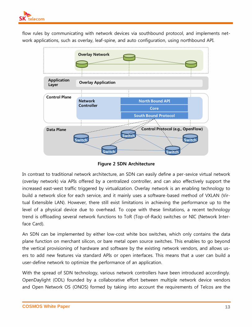
B. Software-Defined Networking (SDN)
SDN refers to a software-based open network control technology that separates the control plane
from network devices, and implements it into a centralized controller, which makes each network
device perform the data plane functions only. As shown in Figure 2, a centralized controller sets up
Virtualization and Processor (CPU): Recently, processors with multiple cores on a single chip enabled to
run more virtual machines without degrading performance. A recent server with 12 processors can create
528 virtual machines (12 processors * 2 hyper-threads * 22 cores), which is not quite different from a
physical server in terms of performance for a single threaded application. In other words, a single physical
server can run as many as 400-500 virtual machines simultaneously.
COSMOS White Paper 13
flow rules by communicating with network devices via southbound protocol, and implements net-
work applications, such as overlay, leaf-spine, and auto configuration, using northbound API.
Figure 2 SDN Architecture
In contrast to traditional network architecture, an SDN can easily define a per-sevice virtual network
(overlay network) via APIs offered by a centralized controller, and can also effectively support the
increased east-west traffic triggered by virtualization. Overlay network is an enabling technology to
build a network slice for each service, and it mainly uses a software-based method of VXLAN (Vir-
tual Extensible LAN). However, there still exist limitations in achieving the performance up to the
level of a physical device due to overhead. To cope with these limitations, a recent technology
trend is offloading several network functions to ToR (Top-of-Rack) switches or NIC (Network Inter-
face Card).
An SDN can be implemented by either low-cost white box switches, which only contains the data
plane function on merchant silicon, or bare metal open source switches. This enables to go beyond
the vertical provisioning of hardware and software by the existing network vendors, and allows us-
ers to add new features via standard APIs or open interfaces. This means that a user can build a
user-define network to optimize the performance of an application.
With the spread of SDN technology, various network controllers have been introduced accordingly.
OpenDaylight (ODL) founded by a collaborative effort between multiple network device vendors
and Open Network OS (ONOS) formed by taking into account the requirements of Telcos are the
Data Plane
Control PlaneNetworkController
South Bound Protocol
Core
North Bound API
Control Protocol (e.g., OpenFlow)
Overlay Network
Overlay ApplicationApplicationLayer
SwitchSwitch
Switch Switch
Switch

COSMOS White Paper 14
two prime examples of open source projects. ONOS, in particular, is currently in the process of de-
veloping a Telco-grade SDN network operating system by reflecting the requirements from Telco.
OpenFlow
OpenFlow is one of the most widely accepted SDN protocols. In 2012, it emerged as a technology
that enables to perform diverse actions, such as packet forwarding, dropping, shaping and reactive
processing, based on the 12 matching fields [13]. Beginning with the OpenFlow technology, a novel
programmable switch technology was introduced, which allows to control the networking of
switches through a software controller and provides only the features that are optimized for a us-
er’s particular needs. As an open source project, OpenFlow is managed by the Open Networking
Foundation (ONF) and the current version of OpenFlow is the 1.5 version. At present, network op-
erating systems that support OpenFlow include ONL (Open Network Linux), Cumulus Linux and
Open Switch.
C. Software-Defined Storage (SDS)
The increasing density of virtual machines in a data center and explosively growing unstructured
data like SNS, IoT and, multimedia gave rise to a challenge to the existing hardware-based storage
system, which is optimized for structured data. Against this backdrop, an SDS technology was in-
troduced, which can be scaled out with changing needs and efficiently operated within the budget
cap.
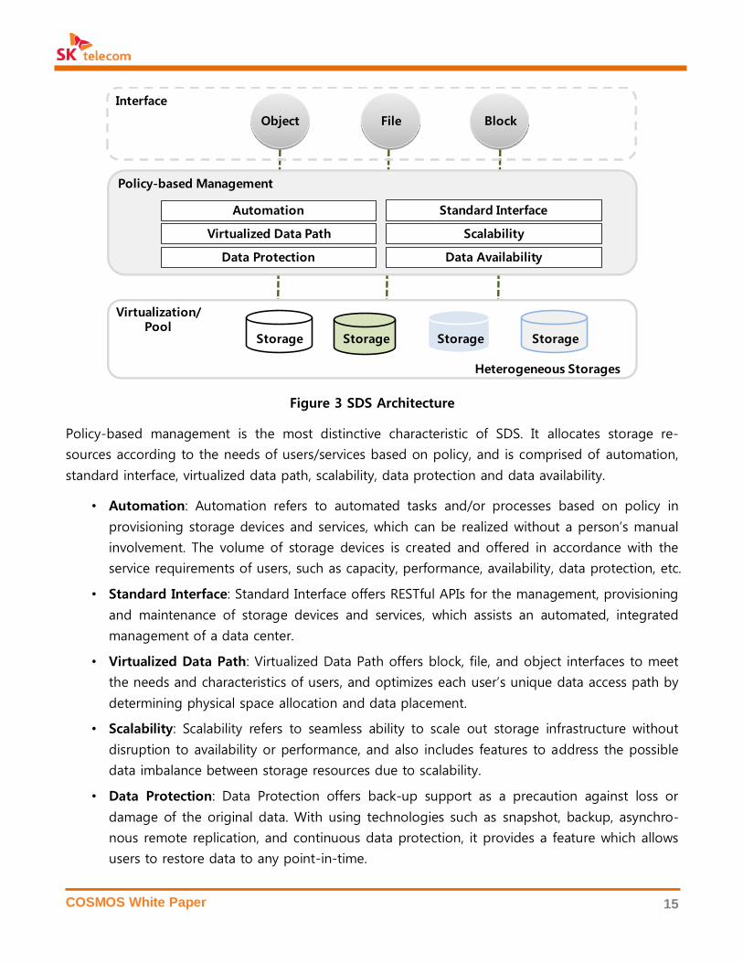
As Figure 3 shows, a software-based controller of an SDS system manages the entire storage sys-
tem in a date center and responds to diverse user and service. SDS integrates physical resources
and then forms a single pool through storage virtualization, thus ensuring scalability, availability
and data protection, etc., via software. In addition, it offers multiple interfaces that support storage
devices – block, object and file storages – as well as fast provisioning with prompt, flexible scalabil-
ity of performance and capacity.
Merchant Silicon is a kind of chipset used in a switch for packet forwarding. With an open architecture, it
allows to support open APIs, thus enabling to be interconnected with a third party operating system.
Bare Metal Switch is a network switch built on merchant silicon. It uses an open architecture, so that us-
ers can select and install various network operating systems and network functions.
COSMOS White Paper 15
Figure 3 SDS Architecture
Policy-based management is the most distinctive characteristic of SDS. It allocates storage re-
sources according to the needs of users/services based on policy, and is comprised of automation,
standard interface, virtualized data path, scalability, data protection and data availability.
• Automation: Automation refers to automated tasks and/or processes based on policy in
provisioning storage devices and services, which can be realized without a person’s manual
involvement. The volume of storage devices is created and offered in accordance with the
service requirements of users, such as capacity, performance, availability, data protection, etc.
• Standard Interface: Standard Interface offers RESTful APIs for the management, provisioning
and maintenance of storage devices and services, which assists an automated, integrated
management of a data center.
• Virtualized Data Path: Virtualized Data Path offers block, file, and object interfaces to meet
the needs and characteristics of users, and optimizes each user’s unique data access path by
determining physical space allocation and data placement.
• Scalability: Scalability refers to seamless ability to scale out storage infrastructure without
disruption to availability or performance, and also includes features to address the possible
data imbalance between storage resources due to scalability.
• Data Protection: Data Protection offers back-up support as a precaution against loss or
damage of the original data. With using technologies such as snapshot, backup, asynchro-
nous remote replication, and continuous data protection, it provides a feature which allows
users to restore data to any point-in-time.
Virtualization/Pool
Object Block
Storage Storage Storage
Automation Standard Interface
Virtualized Data Path Scalability
File
Data Protection Data Availability
Interface
Policy-based Management
Storage
Heterogeneous Storages
COSMOS White Paper 16
• Data Availability: Data Availability offers tolerance and redundancy in case errors occur in
disks, networks, servers, etc. It also allows users to access data when an abnormal situation
occurs. Technologies including replication, RAID, erasure coding and checksum are used in
delivering Data Availability.
Scale-Out Storage
A scale-out storage system that allows capacity and performance expansion on a node basis is
suitable to meet the needs to manage explosively growing data and create values out of data. This
system can improve capacity, performance, and availability of a storage system at the same time,
thus supporting a hyperscale-grade expansion, whereas a scale-up storage can expand within a
limited capacity. It could also lead to TCO reductions by using software-based functionality and
availability. Due to the above-mentioned benefits, scale-out storage is used widely among large-
scale global data centers of Google, Amazon, etc.
Ceph is a leading open source for scale-out storage initiated by the University of California, Santa
Cruz (UCSC) since 2007 based on the main three philosophies: “failure is normal, scale-out on
commodity hardware, and everything runs in software.” Ceph is designed in scale-out architecture
using commodity severs to effectively respond to increasing data usage and to efficiently manage
service flexibility and device operation in integrated manner. Red Hat acquired startup Inktank, the
company behind Ceph, in 2014, and this propelled Ceph to continue expanding its influence.
Being integrated with OpenStack Cinder in 2011, Ceph recorded the highest usage rate against
other commercial and open source solutions in OpenStack community. A survey conducted by the
OpenStack Foundation in October 2015 showed that 37% users selected Ceph [14]. Moreover, its
position as a large-scale object storage system has been solidified as companies like Yahoo [15]
and Bloomberg [16] chose to use Ceph in their data centers.
All-Flash Storage
Flash memory is being widely used in scale-up/scale-out storage systems, as its price per capacity
has been significantly decreasing. In case of scale-up storage systems, traditional vendors like EMC
and NetApp are using flash memory to improve performance by placing a cache located between
DRAM and HDD, while keeping the most parts of the existing system architecture. On the other
hand, new vendors including PureStorage, Nimbus, and Kaminario have preoccupied all-flash stor-
age market by using SATA SSD in storage controllers and devices.
The development of flash-optimized software is being carried out actively for scale-out storage sys-
tems. Major SSD vendors like Intel, SanDisk, and Samsung are currently developing Ceph-based
flash acceleration technologies, and new-comers like SolidFire and ElastiFile have launched their
COSMOS White Paper 17
own all-flash scale-out storage products staying ahead of their rivals in the market. EMC, HP and
other traditional vendors have also joined the all-flash trends
D. OpenStack for SDDC Management
Virtual resource management based on software is a core enabling technology to realize an SDDC,
which allows a data center to control and interconnect a range of virtual resources of SDC, SDN
and. VMware vSphere and Microsoft Hyper-V are examples of commercial virtual resource man-
agement solutions, while OpenStack and CloudStack are best-known examples of open source
software solutions. Among the above-mentioned solutions, OpenStack is widely adopted and main-
stream for virtual resource management. OpenStack is being offered in commercial software pack-
ages by vendors like HP and Red Hat, and it is being used even in the Telco domain, such as ETSI
MANO [17].
OpenStack began as a joint project of Rackspace and NASA in 2010, and then the OpenStack
Foundation was formed in 2012 to promote OpenStack community. Starting with the initial release
of Austin (2010) followed by subsequent releases up to Grizzly (2013), the OpenStack community
offered services that were capable of delivering server virtualization and object-based storage using
APIs. In its later versions from Havana (2013) to Icehouse (2014), however, OpenStack served as a
DevOps platform which led software-driven innovations across development processes by offering
new features such as operation automation, network/storage device virtualization and bare metal
provisioning, etc. With the release of OpenStack Juno (2014), OpenStack has evolved as a platform
that enables to develop and deploy applications backed by new features including application cata-
log, as-a-service features (e.g., load balance, database, DNS, etc.) and, container. OpenStack is un-
dergoing a continuous evolution toward a full-fledged platform to support integration of all re-
sources and technologies of a data center in the near future.
Through the aforementioned technological evolution, OpenStack has positioned as a core architec-
tural component in SDDC operations going beyond its role as a virtual resource manager. Moreo-
ver, as shown by the following cases, multiple enterprises have integrated OpenStack into their IT
environments, thus proving its stability and maturity.
• Comcast: built an on-demand content delivery service system using OpenStack.
- allowing to be prepared for a sudden increase in user traffic (e.g., Super Bowl)
- enabling to support approximately 600 projects and more than 17,000 users
• Walmart: established an OpenStack-based e-commerce system (150,000 CPU cores).
- allowing to track/analyze 27 countries, 11,000 stores and 245 million customers
- offering a cloud infrastructure responding to a dramatic increase of customers and data
COSMOS White Paper 18
• AT&T: built the first OpenStack data center in 2012 and three others in 2014.
- planning to virtualize 75% of the entire network infrastructure by 2020
• Yahoo: currently in the process of integrating all infrastructure based on OpenStack.
- achieving auto-installation of tens of thousands of servers (bare metal provisioning).
- supporting open APIs for the development of customized software
While OpenStack dominates open source virtual machine cluster management, open source solu-
tions for container cluster management have been also unveiled and available, such as Kubernetes,
Apache Mesos, and Docker Swarm, which can create container resources within a few seconds and
perform fast auto-scaling/auto-recovery, which are known as advantages over virtual machine.
Google, for instance, lifted the lid on its internal Borg system and introduced Kubernetes, an open
source container management system, in 2014 and it was applied to OpenShift, a PaaS solution of
Red Hat. As a framework offering an integrated management of diverse cluster resources, Apache
Mesos is used by companies like Verizon, Airbnb and Netflix, etc. Recently, Red Hat demonstrated
the deployment of 50,000 Docker containers in 54 minutes by using Docker Swarm.
1.4 Telco SDDC: All-IT Network
The SDDC innovation, which began in the IT domain, has gradually spread across the Telco domain.
An expansion of virtualization in the scope of Telco infrastructure has encouraged Telcos to pro-
mote the transformation of Telco infrastructure into a data center. Given the movement towards
openness backed by open ecosystem, various attempts have been made to do away with the exist-
ing closed and dependent ecosystem centering around a few vendors.
To drive IT innovation in the Telco sector, a Telco SDDC needs to be designed to satisfy the re-
quirements of telecommunication services. In the 5G era, all network infrastructure will be virtual-
ized and evolved into an All-IT Network based on the network-IT convergence, which must meet
the 5G requirements including 100-1000 times faster speed, 10 times lower latency, and massive
connectivity.
In contrast to OTT services, Telco services provided to paid subscribers have potential to cause di-
rect and significant ripple effects in case performance deteriorates or an error occurs. Therefore, a
stricter latency standard than that adopted by OTT services is needed, and is also required to offer
higher availability to ensure a failover in real-time whenever an error is detected. To meet the
above-mentioned needs, a Telco SDDC is required to re-architecture infrastructure to optimize the
applications of NFV (Network Function Virtualization), which are offered by dedicated hardware;
and to develop Telco-grade SDN technologies.

COSMOS White Paper 19
In contrast to the existing Telco network where hardware and software are vertically integrated for
each specific network function, such as EPC, MME, and IMS, Telco SDDC serves as a horizontal in-
frastructure platform, which accommodates diverse VNF (Virtualized Network Functions) applica-
tions. In All-IT Network, therefore, engineering, development, and operation are also separated hor-
izontally between Telco SDDC and VNF, for which required competence and work will be varied.
Telco-Grade NFV
NFV applications usually require higher speed and/or lower latency than OTT applications, such as
large-scale packet processing and flexible configurations between VNFs, which must be supported
in a Telco SDDC. The following technologies to achieve these requirements are being developed
and adopted by a Telco SDDC:
• Network Acceleration: Running Telco VNF applications on virtual machines gives rise to a
network delay since forwarding process of packets goes through the virtualization layer. To
solve this issue, technologies that accelerate packet processing, such as DPDK (Data Plane
Development Kit) and SR-IOV (Single Root – Input Output Virtualization) are essential in NFV.
• VNF Component: Instead of using a dedicated hardware, VNF configurations must be mod-
ular and composable to respond to diverse service requirements in a flexible manner. Each
VNF needs to be further decomposed into multiple VNF components, which can be reas-
sembled and reconfigured whenever it is needed in order to achieve flexibility and speed
with regard to delivery of end-user services.
• NFV on Container: Containerized Network Function (CNF) is currently under investigation,
which allows VNF applications running directly on a physical server using container technol-
ogy rather than a virtual machine. CNF is gaining increasing attention thanks to the benefits:
it enables to bring performance up to the level of a physical server, and offers faster auto-
scaling and auto-recovery than a virtual machine.
• Rack Scale Architecture: When designing data center hardware, it is necessary to consider a
new approach like Intel’s Rack Scale Design (RSD), which disaggregates the existing physical
server into component level (i.e., CPU, memory, disk, network, etc.) within a rack and dynam-
ically re-assembles them in a form appropriate for the provisioning of services. This new
concept of rack scale architecture is designed to maximize the hardware utilization of a data
center and to meet the service-specific requirements defined by an SLA (Service Level
Agreement) for NFV.
Telco Grade SDN
In order to ensure continuity and performance of Telco services, a Telco SDDC network is demand-
ed to offer higher levels of services. For this purpose, Telco-grade SDN technologies are currently

COSMOS White Paper 20
under development and employment, such as segment routing, network controller clustering,
VXLAN, Overlay Networking by MPLS (Multiprotocol Label Switching), and overlay network for multi
or hybrid data center, etc.
• High Throughput & Low Delay: A more sophisticated traffic engineering, such as segment
routing built with SDN technology is required to improve the performance of east-west traf-
fic between NFV’s virtualized functions.
• High Availability & Scalability: In addition to the high availability of network devices, it is
necessary to ensure the availability of an SDN controller and the reliability of network ser-
vices deployed on the controller. To achieve this, the SDN controller is designed to support
clustering to guarantee high availability and scalability. For example, ONOS in pursuit of a
carrier-grade network controller supports clustering using its high-performance distributed
architecture. The latest release of ODL, known as Beryllium, also embraced clustering feature.
• Overlay Networking: A virtual network between virtual machines must be unrestricted and
independent to support diverse types of service chaining, which requires overlay networking
based on VXLAN or MPLS GRE (Multi-Protocol Label Switch General Routing Encapsulation).
OpenContrail, for instance, which was developed and open sourced by Juniper Networks
supports this feature. ONOS also supports VXLAN-based overlay network that could be in-
teroperable with OpenStack via Neutron API.
• Inter Data Center Networking: For NFV’s use cases such as mobile edge computing, seam-
less inter-data center networking between the edge cloud and the central cloud is required
by using high speed MPLS routing. Overlay networking for multi or hybrid data centers is al-
so necessary.
Figure 4 ONOS Architecture
Northbound Core API
Distributed Core(State management, Notifications, High-availability & Scale-out)
Southbound Core API
Protocols
Adapters
Protocols
Adapters
Protocols
Adapters
Protocols
Adapters
Apps
COSMOS White Paper 21
ONOS (Open Network Operating System) is an open source project for a Telco-grade network control-
ler. In contrast to OpenDaylight (ODL), which is led by network device vendors, ONOS is a Telco-led open
source project hosted by the ON.Lab along with other industry partners and developers. Following the
first release, Avocet, a new version became public based every four months. ONOS launched its 6th re-
lease, Falcon, in March 2016. ONOS is based on distributed architecture from the beginning, and it allows
users to build a cluster by itself. SDN-IP, BGP Router and CORD are well-known use cases. SK telecom
participates in ONOS as a partner with voting rights, and leads M-CORD project.
COSMOS White Paper 22
2. SK TELECOM VISION ON SDDC: COSMOS
This chapter defines the design principles for the architecture of a Telco SDDC and presents the
next generation infrastructure of SK telecom: COSMOS (Composable, Open, Scalable, Mobile-
Oriented System). Also, ATSCALE, which is based on COSMOS as its infrastructure, is introduced as
the evolution of Telco network of SK telecom.
2.1 Design Principles of COSMOS
The fundamental principle of COSMOS is to offer different types of services of SK telecom on a
single virtualized cloud infrastructure. Thus, COSMOS refers to ‘universal infrastructure’ that enables
a number of distributed data centers to encompass not only platform services (e.g., multimedia,
lifestyle, IoT, etc.) and internal IT services (e.g., BSS, ERP, SCM, etc.), but NFV applications for Telco
services.
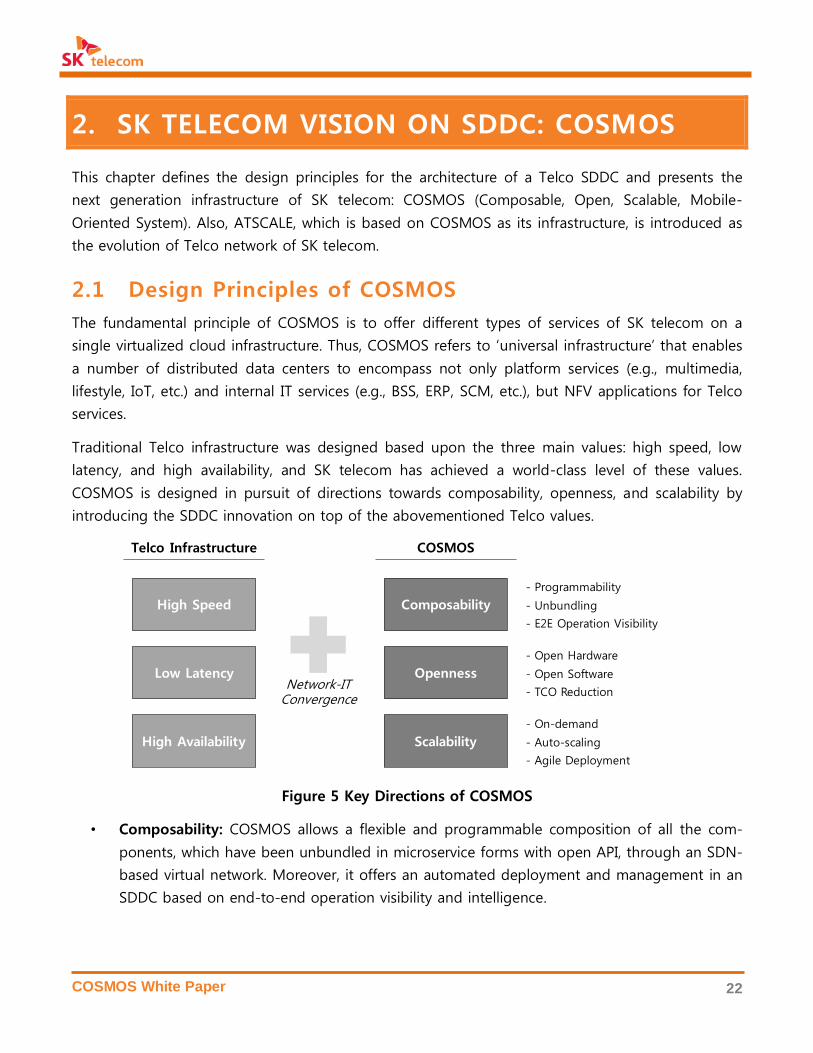
Traditional Telco infrastructure was designed based upon the three main values: high speed, low
latency, and high availability, and SK telecom has achieved a world-class level of these values.
COSMOS is designed in pursuit of directions towards composability, openness, and scalability by
introducing the SDDC innovation on top of the abovementioned Telco values.
Figure 5 Key Directions of COSMOS
• Composability: COSMOS allows a flexible and programmable composition of all the com-
ponents, which have been unbundled in microservice forms with open API, through an SDN-
based virtual network. Moreover, it offers an automated deployment and management in an
SDDC based on end-to-end operation visibility and intelligence.
High Speed
Telco Infrastructure
Low Latency
High Availability
COSMOS
Composability
Openness
Scalability
Network-ITConvergence
- Programmability
- Unbundling
- E2E Operation Visibility
- Open Hardware
- Open Software
- TCO Reduction
- On-demand
- Auto-scaling
- Agile Deployment

COSMOS White Paper 23
• Openness: COSMOS aims to keep the TCO structure lean and to adopt the up-to-date
technologies by using open source software and hardware presented by multiple vendors or
developers in order to break existing vendor lock-in. SK telecom offers full supports to the
open communities and plans to contribute internally developed technologies upstream. For
the features that require high-level performance in parallel with open source, specialized
hardware could be used for performance acceleration, but the relevant interfaces will be
made open to be interoperated with other technologies.
• Scalability: COSMOS is based on a scale-out architecture by virtualization in order to cope
with constantly growing demand, volume, and diversity from SK telecom’s customers and
services. This should not only be capable of accommodating the dynamics of short-term
service demands, but has to ensure performance and availability through software when
scaling out servers, switches and storage devices in a long-term perspective.
Figure 6 shows the high-level architecture of COSMOS and ATSCALE. ATSCALE is an evolved model
of SK telecom’s Telco network, which use COSMOS for its infrastructure. COSMOS is rather a hori-
zontal platform, which covers diverse services ranging from to OTT services to Telco services and
internal IT services; while ATSCALE, on the other hand, is a vertical platform to offer Telco services
along with network orchestrator and service orchestrator that manage all of Telco functions.
Figure 6 Evolution of SK telecom Infrastructure: COSMOS and ATSCALE
COSMOS is specifically designed based on the following principles:
VirtualizedEdge
Functions
Compute Network Storage
Physical Resource / Open Hardware
Virtualization Layer
SDC SDN SDS
Virtual Resource / Open Software
Virtual ResourceManagement
Monitoring/Automation
VirtualizedTransportFunctions
VirtualizedCore
Functions
Physical Resource Management
Mobile/Fixed Network Service
E2E Network Orchestration
Service Orchestration &Exposure
Telco Service
OSS
SCM
Platform & Enterprise IT Service
BSS
ERP
Media
Lifestyle IoT
COSMOS
ATSCALE

COSMOS White Paper 24
1) COSMOS’s hardware shall be based on open source hardware.
• Apply open source hardware technology not only to physical servers, network and stor-
age devices, but to integrated management of all hardware devices.
• Cooperate closely with global open source powerhouses (e.g., Facebook OCP and Intel
RSD, etc.) both downstream and upstream, in order to develop and internalize open
source hardware technologies.
• Use SSD for high-performance storage devices to realize all-flash SDS
• Use hardware acceleration technologies such as SSD, FPGA and GPGPU for workloads re-
quiring high performance and make their interfaces public to support interconnections
with other open source hardware devices.
2) COSMOS’s software shall be based on open source software.
• Develop and internalize key open source software technologies, which are industry de
facto standards, including OpenStack, Docker, Spark, ONOS and Ceph, etc.
• Use open source solutions that are being widely used (downstream), and develop differ-
entiated features, which are contributed to open communities (upstream).
• Conduct an integrated and automated operation of various solutions by an SDDC-scale
orchestrator.
3) Each solution of COSMOS shall run independently as a module.
• Ensure that each solution provides an open RESTful API, and construct an SDDC by or-
ganically integrating and interconnecting diverse solutions of COSMOS
4) COSMOS shall support All-IT Network for Telco infrastructure.
• Design in a way to meet the requirements for SDN/NFV.
5) The state-of-the-art technologies that comprise COSMOS shall be capable of accommodat-
ing the existing equipment on the best effort basis.
• Develop adapters and plug-ins for the existing equipment on the best effort basis.
• Support the interconnection and operational management for non-virtualized equipment.
2.2 COSMOS Architecture
As a Telco SDDC, COSMOS shall embrace different applications for both Telco and platform busi-
nesses of SK telecom. It shall also deliver a data platform, which allows to store and use vast
amounts of diverse data generated from both Telco and platform businesses. To satisfy such vary-
ing needs and requirements, COSMOS is built using a collection of open source technologies. The
table below explains the requirements of services supported by COSMOS as well as corresponding
technologies used to meet such demands.

COSMOS White Paper 25
Businesses Requirements Enabling Technologies
Telco
• Ultra high speed and low la-
tency defined for 5G
• Telco-grade service reliability
• SDN-based data center networking
• Network acceleration by OVS-DPDK
• Container-based NFV
• Operation automation and intelligence
Multimedia • Minimized network delay
• Ultra-high throughput
• SDN-based data center networking
• SSD-based high speed streaming
IoT • Massive connectivity
• Ultra low latency
• Fine-grained resource allocation by container
• Policy-based QoS control
Big Data • Large-scale unified storage
• Real-time data analytics
• Key-value-based object storage
• Interface for heterogeneous storage
• SSD-based data processing acceleration
Table 1 Requirements for COSMOS and Enabling Technologies
COSMOS is designed from three different perspectives of Service View, DevOps View, and Operator
View. COSMOS takes Service View to satisfy service quality and performance, DevOps View to pro-
vide convenience and agility for application development, and Operator View to deliver operation
automation and interworking with other systems. Figure 7 depicts a high-level view of COSMOS
architecture and its components.
Figure 7 COSMOS Overall Architecture
SDC SDN SDS
Open Source Hardware + Specialized Hardware
Open H/WServer
Open H/WStorage
All-FlashMedia Server
PCIe JBOF
Open H/W Switch Network Appliance
Leaf-Spine Fabric
SDDC Operation Automation & Intelligence
Virtual Resource Mgmt.(OpenStack)
SDN Controller(ONOS)
SDS Controller(Ceph)
VirtualMachine
Container SONASDN Fabric
AllFlash
UnifiedInterface
Bare Metal/SoftwareProvisioning
Integrated Data Collection
Data Analytics & Visualization
Virtual Resource Management
Private Cloud (IaaS) DevOps Platform (PaaS)
OTT ServicesCommunication, Media, etc.
Telco ServicesLTE, LoRa, 5G, OSS, etc.
Enterprise IT ServicesBSS, ERP, Big Data, etc.
OpenHardware
(Physical Infrastructure)
OpenSoftware
(Virtual Infrastructure)
Unbundled
Applications
Cloud Service
COSMOS White Paper 26
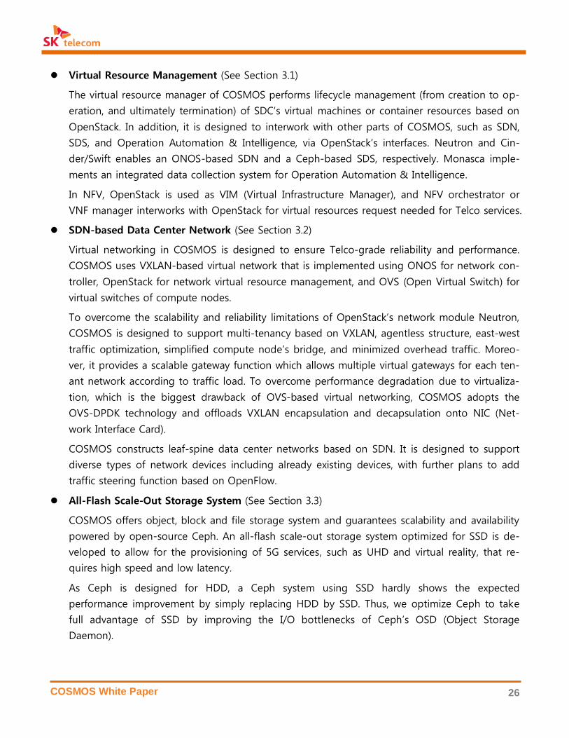
Virtual Resource Management (See Section 3.1)
The virtual resource manager of COSMOS performs lifecycle management (from creation to op-
eration, and ultimately termination) of SDC’s virtual machines or container resources based on
OpenStack. In addition, it is designed to interwork with other parts of COSMOS, such as SDN,
SDS, and Operation Automation & Intelligence, via OpenStack’s interfaces. Neutron and Cin-
der/Swift enables an ONOS-based SDN and a Ceph-based SDS, respectively. Monasca imple-
ments an integrated data collection system for Operation Automation & Intelligence.
In NFV, OpenStack is used as VIM (Virtual Infrastructure Manager), and NFV orchestrator or
VNF manager interworks with OpenStack for virtual resources request needed for Telco services.
SDN-based Data Center Network (See Section 3.2)
Virtual networking in COSMOS is designed to ensure Telco-grade reliability and performance.
COSMOS uses VXLAN-based virtual network that is implemented using ONOS for network con-
troller, OpenStack for network virtual resource management, and OVS (Open Virtual Switch) for
virtual switches of compute nodes.
To overcome the scalability and reliability limitations of OpenStack’s network module Neutron,
COSMOS is designed to support multi-tenancy based on VXLAN, agentless structure, east-west
traffic optimization, simplified compute node’s bridge, and minimized overhead traffic. Moreo-
ver, it provides a scalable gateway function which allows multiple virtual gateways for each ten-
ant network according to traffic load. To overcome performance degradation due to virtualiza-
tion, which is the biggest drawback of OVS-based virtual networking, COSMOS adopts the
OVS-DPDK technology and offloads VXLAN encapsulation and decapsulation onto NIC (Net-
work Interface Card).
COSMOS constructs leaf-spine data center networks based on SDN. It is designed to support
diverse types of network devices including already existing devices, with further plans to add
traffic steering function based on OpenFlow.
All-Flash Scale-Out Storage System (See Section 3.3)
COSMOS offers object, block and file storage system and guarantees scalability and availability
powered by open-source Ceph. An all-flash scale-out storage system optimized for SSD is de-
veloped to allow for the provisioning of 5G services, such as UHD and virtual reality, that re-
quires high speed and low latency.
As Ceph is designed for HDD, a Ceph system using SSD hardly shows the expected
performance improvement by simply replacing HDD by SSD. Thus, we optimize Ceph to take
full advantage of SSD by improving the I/O bottlenecks of Ceph’s OSD (Object Storage
Daemon).

COSMOS White Paper 27
Moreover, functions such as management tool, data deduplication/compression, and QoS guar-
antee are included to ensure stable performance in cloud environment. A GUI dashboard is also
offered for operational convenience.
SDDC Operation Automation & Intelligence (See Section 3.4, Section 3.5, and Section 3.6)
Data center automation functions offered by COSMOS include control and configuration man-
agement of physical and virtual resources across multiple data centers in a unified manner, as
well as automatic installation/distribution of operating system and software. In other words, an
administrator from a remote place can install or upgrade OS and default software on bare met-
al servers, delivering automation of manual tasks and mistake-proofing for administrators.
Moreover, it is designed to improve operational efficiency by empowering administrators to
easily identify the current status of equipment, which is needed for the management of physi-
cal and virtual resources inventory, equipment location and utilization, hardware/software
maintenance, application status management, and adoption of new equipment and services.
After collecting all the information required for data center operation by using OpenStack
Monasca and Apache Kafka, COSMOS performs real-time usage and load monitoring of each
resource, and notifies administrators when they hit critical threshold. It also collects and analyz-
es metric and log data for the provisioning of anomaly detection function that is capable of
identifying complicated patterns which are not easy for administrators to detect manually. The
analysis results (alarm, automatic action, etc.) are then visualized to administrators. Technolo-
gies such as 3D visualization can be used for effective representation of complicated network
information that changes dynamically in SDN-based data center network.
Open Source Hardware
The servers, switches, and storages in COSMOS primarily use open source commodity hardware,
whose functions can be defined by software. OCP hardware is being tested to be adopted in
COSMOS for the applications of OpenStack, Hadoop, and NFV. The test will verify the known
benefits of OCP, such as better equipment density and power efficiency in SK telecom’s envi-
ronment. Use of OCP for NFV, in particular, is being developed in OCP Telco Project, where the
requirements in terms of performance, environment, and operation will be defined for the
adoption of OCP in Telco infrastructure.
OCP is also adopting SSD and GPGPU when high level of performance is required as with the
case of artificial intelligence and NFV. In addition, COSMOS is continuously on the lookout for a
new concept of hardware for adoption, such as Intel’s Rack Scale Design.
PCIe JBOF (See Section 4.1 and Section 4.2)
In order to deliver high-volume, low-latency services for the 5G era, COSMOS leverages NVMe
(Non-Volatile Memory express) SSD to maximize storage performance. In particularly, JBOF (Just

COSMOS White Paper 28
a Bunch of Flash), a high-density storage system built on NVMe SSD, is also in the pipeline,
with aims to expand storage capacity and share it between servers. JBOF adopts PCIe (Periph-
eral Component Interconnect express) switching to address bottlenecks at SAS/SATA interface
and deliver high-speed performance.
As present, a single JBOF system supports up to 20 NVMe SSDs in a 1U chassis, which is
shared by multiple servers. JBOF will be used as a component of all-flash scale-out storage,
Hadoop storage, or other appliances in COSMOS.
All-Flash Media Server (See Section 4.4)
There is an exponential growth in the volume of multimedia services, and the way of multime-
dia consumption is shifting from downloading towards streaming. Media servers must embrace
such changes and evolve into all-flash storage arrays. All-flash media server built on low-power
CPU, combines high-performance SSD and high-speed NIC (Network Interface Card) technolo-
gies, which makes it optimal for media streaming. Its use of SSD and removal of unnecessary
components allows it to deliver higher speed and density, along with lower energy consump-
tion compared to existing HDD-based systems.
Network Appliance (See Section 4.5)
As part of its efforts to efficiently support various on-demand network applications, COSMOS
incorporates SDN/NFV based network technologies into Top of Rack (ToR) switches as a net-
work appliance. It serves as an integrated network service platform built on open source com-
modity hardware that delivers both the basic functions of ToR switch (L2) and network applica-
tion functions of general servers from a single device. As such is the case, TCO savings and in-
frastructure simplicity can be achieved.
Network applications provided by the network appliance include firewall, load balancer, and
VPN, with further plans to expand the scope of its applications by adding monitoring and net-
work analysis.
Private Cloud (IaaS) (See Section 5.1)
All virtual resources of COSMOS are delivered on an on demand basis in self-service environ-
ment. Users can operate virtual machines within minutes through OpenStack, without having to
prepare hardware firsthand. Standard templates enable users, even those unfamiliar with infra-
structure configuration, to easily create virtual machine environment. In the event of errors,
alarms are generated to enable users to deal with problems immediately.
As COSMOS’s private cloud service reflects SK telecom’s IT policies, it relieves users the burden
of going through complicated security procedures to meet security requirements and regulato-
ry environment. Moreover, it also allows interworking with other systems in the company.
DevOps Platform (PaaS) (See Section 5.2)

COSMOS White Paper 29
COSMOS provides a PaaS service based on Cloud Foundry when users are in need of a devel-
opment and operating environment for their applications, and not concerned about the com-
position of virtual infrastructures. Cloud Foundry provides Docker-based container services,
while applications, not only written in cloud programming languages such as Java and Python,
but also developed in C/C++, can be deployed in a binary package form. PaaS also makes
available various DevOps standard environment required for development, such as database,
WAS (Web Application Server), and source code management. Moreover, it can be intercon-
nected with Telco services, such as SK telecom’s authentication, SMS/MMS, and location tech-
nology.
COSMOS will support Telco functions running on containers, and PaaS plans to go beyond its
current role as IT DevOps platform for OTT services, and transform itself into a DevOps plat-
form for NFV.
The above-mentioned systems are only a few examples of the technologies adopted by COSMOS.
Open source software, open source hardware, and cloud services are described more in details in
Chapter 3, 4, and 5, respectively. Please refer to Appendix for an overall mapping of COSMOS pro-
jects.
2.3 Anticipated Benefits
As an infrastructure platform that supports SK telecom’s diverse business, COSMOS guarantees per-
formance and reliability. Another important benefit that cannot be left out is TCO savings effect.
TCO savings can be broken down into cost optimization of three resources of CAPEX, OPEX, and
time, as stated in Figure 8.
Figure 8 TCO Savings of COSMOS
CAPEXSoftware
Hardware
• Minimize or remove license fee through internalization of open source solutions
• Opt for ODM purchasing and avoid vendor lock-in by using open source hardware
OPEXOperation
Footprint
Energy
• Increase operation efficiency by software-based automation and intelligence
• Design and use high-density hardware
• Design and use hardware with low power consumption
Time Time-to-Market • Deliver agile DevOps environment by self-service provisioning
Volume • Optimize investment by improving scalability and utilization of infrastructure
through virtualization

COSMOS White Paper 30
Using open source software and hardware directly leads to CAPEX savings in terms of hardware
and software procurement, which can be realized by opting for new procurement options such as
purchasing hardware directly from ODM and minimizing software license fees by internalizing open
source software. In addition, virtualization of resources improves utilization and scalability, which in
turn optimizes infrastructure investment.
From the perspective of OPEX, automation/intelligence can increase the number of equipment each
administrator manages, which is a significant factor in a large-scale data center. Energy-efficient
power and cooling design can translate into savings on electric power bill and realty costs.
Although the resource of time is not directly reflected in financial indicators, it is one of the most
important resources in the current business environment that is driven by fast-changing customer
demands and technologies. In such a business environment, competitive edge in time-to-market
has the power to make or break a business. Ceaseless updates based on DevOps are one of the
few ways to cater to the demands of tricky customers. In this respect, COSMOS can contribute to
dramatic reductions in time-to-market with the provisioning of an agile development environment
or self-service environment based on virtualization.
2.4 Network Evolution of SK telecom: ATSCALE
ATSCALE is the next-generation network of SK telecom designed with the five key directions: scala-
ble, cognitive, automated, lean, and end-to-end. As illustrated in Figure 9, COSMOS provides run-
ning environment of all virtualized network functions, which means COSMOS serves as the underly-
ing infrastructure layer of ATSCALE.
Overall, COSMOS is in charge of infrastructure functionality that provisions virtual resources of SDC,
SDN, and SDS, and thus diverse network functions are running as applications of COSMOS. Service
Orchestrator or VNF Manager sends a request for virtual resources to VIM (Virtual Infrastructure
Manager) of COSMOS, and VIM’s OpenStack creates the requested resources. COSMOS also pro-
vides NG-OSS with necessary information for infrastructure monitoring and automation.
The two building blocks of Telco infrastructure – Distributed Edge Cloud (Edge Data Center) and
Centralized Cloud (Centralized Data Center) – are built based on COSMOS, and the key technology
domains that run on these two building blocks are described below:

COSMOS White Paper 31
Figure 9 ATSCALE Architecture
① SDRAN (Software-Defined RAN): As a domain providing wireless connections to offer
mobile communications services to customers and managing features including allocation,
cancellation and scheduling of wireless resources, SDRAN supports provisioning of edge
services and operation through network virtualization based on open hardware, software
and interfaces.
② vCore (Virtualized Core): As a domain offering the fundamental features of mobile tele-
communications services namely authentication, session management, mobility manage-
ment, charging control and value-added services, vCore allows to unbundle(or decouple)
and re-design traditional complex architecture by modular (or unit) function (Control/User
plane) to achieve simplification, and re-bundle/re-deploy the functions divided into a mod-
ular unit in accordance with service requirements, and thus delivering an optimized core
network.
vCore
Edge DC Centralized DC
Open & Programmable H/W
Transport Infrastructure
TransportOpen H/W
POTN
Resource Abstraction Layer
End-to-end Network Orchestration
Local NFV Orchestrator Transport Infra Orchestrator
Service Orchestration and Exposure
Low Latency Service
Immersive Media
Telco Service
Virtualized Network Slice #1
#2#N
Unifie
d-O
Fronthaul
WAN
Open & Programmable H/W
L1/L2
RF
Remote Unit
4G
5G
CO
SM
OS
SDRAN
Virtualized Network Functions
RNF CNF
Network Service Functions
TNF
uCTN
Mobile Connectivity Functions
ESF CSF OSF
NG
-OSS
(E2E H
ybrid
Reso
urce
Mgm
t., Cognitive
& In
tellig
ent A
uto
matio
n)
uCTN

COSMOS White Paper 32
③ uCTN (Unified & Converged Transport Network): As a domain responsible for network
connectivity, uCTN performs unified and converged transportation and control of data
across the distance from radio access to core network and IX (Internet Exchange)
④ Unified-O (Unified Orchestration): As a domain that allows to realize End-to-End network
and service agility based on an integrated control and automation, Unified-O is responsible
for ensuring a vendor-independent control and consistent end-to-end policy implementa-
tion and automation.
⑤ NG-OSS: As a domain dedicated to service and network assurance, NG-OSS offers cogni-
tive & intelligent automation based on End-to-End hybrid resource management and ana-
lytics. It also allows Zero-touch operation by establishing closed-loop with End-to-End Or-
chestration.
Details of technology domains are described in ATSCALE White Paper [18].
COSMOS White Paper 33
3. OPEN SOURCE SOFTWARE IN COSMOS
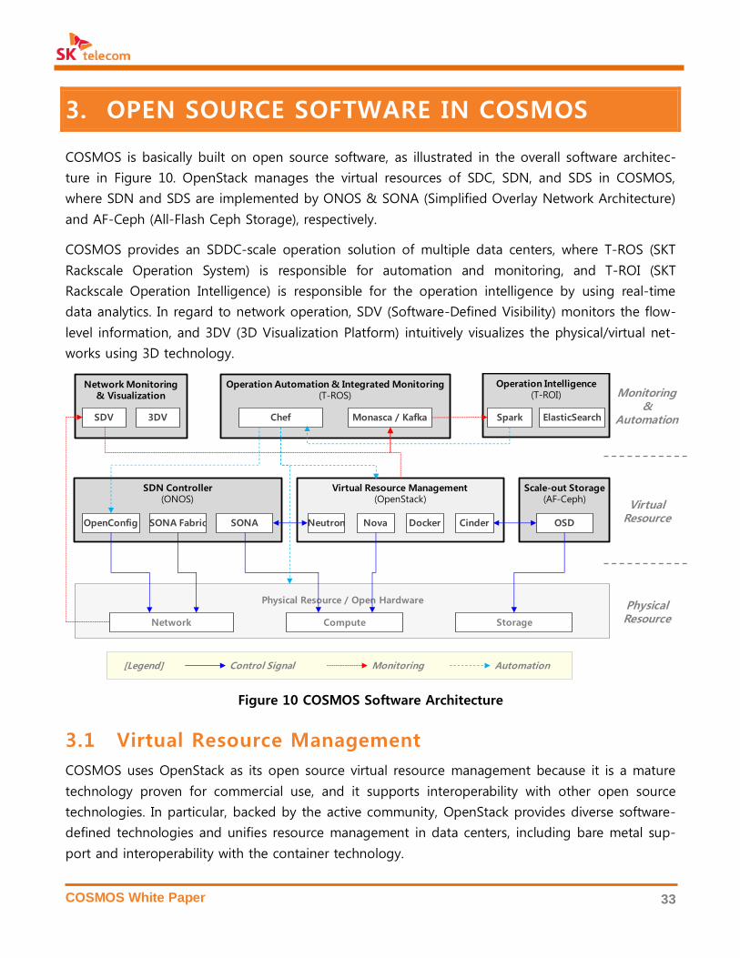
COSMOS is basically built on open source software, as illustrated in the overall software architec-
ture in Figure 10. OpenStack manages the virtual resources of SDC, SDN, and SDS in COSMOS,
where SDN and SDS are implemented by ONOS & SONA (Simplified Overlay Network Architecture)
and AF-Ceph (All-Flash Ceph Storage), respectively.
COSMOS provides an SDDC-scale operation solution of multiple data centers, where T-ROS (SKT
Rackscale Operation System) is responsible for automation and monitoring, and T-ROI (SKT
Rackscale Operation Intelligence) is responsible for the operation intelligence by using real-time
data analytics. In regard to network operation, SDV (Software-Defined Visibility) monitors the flow-
level information, and 3DV (3D Visualization Platform) intuitively visualizes the physical/virtual net-
works using 3D technology.
Figure 10 COSMOS Software Architecture
3.1 Virtual Resource Management
COSMOS uses OpenStack as its open source virtual resource management because it is a mature
technology proven for commercial use, and it supports interoperability with other open source
technologies. In particular, backed by the active community, OpenStack provides diverse software-
defined technologies and unifies resource management in data centers, including bare metal sup-
port and interoperability with the container technology.
Neutron Nova Cinder
Virtual Resource Management(OpenStack)
Scale-out Storage(AF-Ceph)
OpenConfig SONA Fabric SONA
SDN Controller(ONOS)
OSD
Network Compute Storage
Physical Resource / Open Hardware
Chef Monasca / Kafka
Operation Automation & Integrated Monitoring(T-ROS)
3DVSDV
Network Monitoring& Visualization
ElasticSearchSpark
Operation Intelligence(T-ROI) Monitoring
&Automation
VirtualResource
PhysicalResource
Control Signal Monitoring Automation[Legend]
Docker

COSMOS White Paper 34
OpenStack provides the basic technology components for cloud services: compute, storage, net-
working, orchestration, security, backup, etc., but it does not provide a solution that integrates the
components into commercial implementation. Thus, it is necessary to define the specific require-
ments for SK telecom and to decide the necessary technology components to apply OpenStack to
SK telecom’s infrastructure. Also, engineering competence and experience are important for the
deployment architecture, installation/configuration automation, network modeling, monitoring
method, and process implementation. Furthermore, the upgrade path for the new versions of
OpenStack, which are released every six months, is essential for commercial implementation.
A phased approach has been taken to internally build engineering competency and experience in
applying OpenStack at SK telecom. First, strategic collaboration with a partner who is leading the
community and offering commercial solutions is considered necessary for a reliable initial commer-
cialization. The collaboration helps building internal operation experience and developing the nec-
essary solutions. In COSMOS, we have developed solutions for automation, monitoring, data analyt-
ics, user portal, etc., for commercialization, and have built the network model and deployment ar-
chitecture optimized for SK telecom.
OpenStack in COSMOS
COSMOS uses OpenStack to manage its virtual resources and expands its functions for opera-
tion/deployment and interoperability with the other systems of SK telecom. OpenStack interacts
with SDN network (SONA), SSD scale-out storage (AF-Ceph), operation automation (T-ROS), opera-
tion intelligence (T-ROI). OpenStack also serves as a foundation for cloud services: Private Cloud 2.0
(IaaS) and T-Fabric (PaaS) as illustrated in Figure 11.
Figure 11 OpenStack and Related Projects in COSMOS
NOVA HEAT
NEUTRON MONASCA
T-Fabric Private Cloud 2.0
VirtualMachine/Network
ImageUsage, Template
VirtualMachine/Network
AF-CephT-ROS/T-ROI/3DVSONA
Virtual Network Monitoring Block Storage
CINDER
StorageUsage
GLANCE
ImageStorage
COSMOS Services
OpenStack
COSMOS Functions
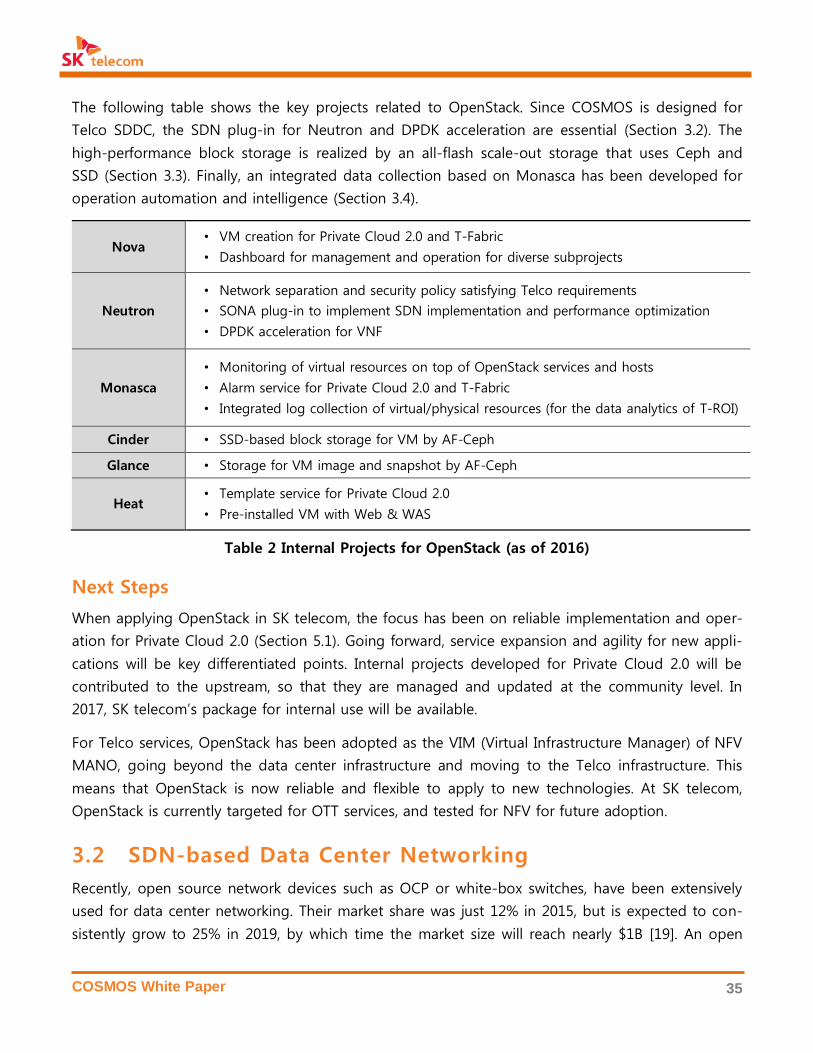
COSMOS White Paper 35
The following table shows the key projects related to OpenStack. Since COSMOS is designed for
Telco SDDC, the SDN plug-in for Neutron and DPDK acceleration are essential (Section 3.2). The
high-performance block storage is realized by an all-flash scale-out storage that uses Ceph and
SSD (Section 3.3). Finally, an integrated data collection based on Monasca has been developed for
operation automation and intelligence (Section 3.4).
Nova • VM creation for Private Cloud 2.0 and T-Fabric
• Dashboard for management and operation for diverse subprojects
Neutron
• Network separation and security policy satisfying Telco requirements
• SONA plug-in to implement SDN implementation and performance optimization
• DPDK acceleration for VNF
Monasca
• Monitoring of virtual resources on top of OpenStack services and hosts
• Alarm service for Private Cloud 2.0 and T-Fabric
• Integrated log collection of virtual/physical resources (for the data analytics of T-ROI)
Cinder • SSD-based block storage for VM by AF-Ceph
Glance • Storage for VM image and snapshot by AF-Ceph
Heat • Template service for Private Cloud 2.0
• Pre-installed VM with Web & WAS
Table 2 Internal Projects for OpenStack (as of 2016)
Next Steps
When applying OpenStack in SK telecom, the focus has been on reliable implementation and oper-
ation for Private Cloud 2.0 (Section 5.1). Going forward, service expansion and agility for new appli-
cations will be key differentiated points. Internal projects developed for Private Cloud 2.0 will be
contributed to the upstream, so that they are managed and updated at the community level. In
2017, SK telecom’s package for internal use will be available.
For Telco services, OpenStack has been adopted as the VIM (Virtual Infrastructure Manager) of NFV
MANO, going beyond the data center infrastructure and moving to the Telco infrastructure. This
means that OpenStack is now reliable and flexible to apply to new technologies. At SK telecom,
OpenStack is currently targeted for OTT services, and tested for NFV for future adoption.
3.2 SDN-based Data Center Networking
Recently, open source network devices such as OCP or white-box switches, have been extensively
used for data center networking. Their market share was just 12% in 2015, but is expected to con-
sistently grow to 25% in 2019, by which time the market size will reach nearly $1B [19]. An open

COSMOS White Paper 36
source network device requires an open network OS, such as Cumulus Linux or OpenSwitch, and
various open APIs for the network controller, such as SAI (Switch Abstraction Interface) or OVSDB
(Open Virtual Switch DB), which have developed continuously.
COSMOS builds its physical leaf-spine fabric using such open source switches. SDN technologies
based on ONOS realize the virtual network management, the leaf-spine fabric management, and
the network monitoring system. Figure 12 illustrates the overall SDN architecture, where the key
components are as follows:
• SONA (Simplified Overlay Networking Architecture): VXLAN-based virtual network man-
agement system
• SONA Fabric: Leaf-spine fabric management for data center networking
• OpenConfig-based Configuration Automation: Automated switch configuration interwork-
ing with T-ROS in Section 3.4
The network monitoring (SDV) and the visualization platform (3DV), also described in Figure 12, will
be addressed in Section 3.6.
Figure 12 Software Architecture for SDN-based Data Center Network
SONA (Simplified Overlay Network Architecture)
SONA is an optimized multi-tenancy network virtualization solution as a core component of SK tel-
ecom’s vision of All-IT Network. It uses OpenStack Neutron API with no modifications and is thus
completely compatible with any OpenStack-based system. The main features of SONA are as fol-
lows:
SONA
3DV
SDV
T-ROS
Yang
Flow Info
Traffic Info
Flow Rules
ConfigurationAction
SONAFabric
Link Info
ONOS
ServersSwitches
ConfigurationAutomation
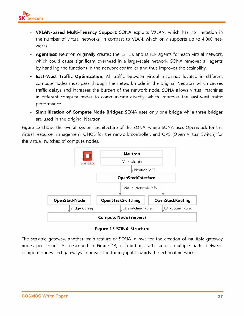
COSMOS White Paper 37
• VXLAN-based Multi-Tenancy Support: SONA exploits VXLAN, which has no limitation in
the number of virtual networks, in contrast to VLAN, which only supports up to 4,000 net-
works.
• Agentless: Neutron originally creates the L2, L3, and DHCP agents for each virtual network,
which could cause significant overhead in a large-scale network. SONA removes all agents
by handling the functions in the network controller and thus improves the scalability.
• East-West Traffic Optimization: All traffic between virtual machines located in different
compute nodes must pass through the network node in the original Neutron, which causes
traffic delays and increases the burden of the network node. SONA allows virtual machines
in different compute nodes to communicate directly, which improves the east-west traffic
performance.
• Simplification of Compute Node Bridges: SONA uses only one bridge while three bridges
are used in the original Neutron.
Figure 13 shows the overall system architecture of the SONA, where SONA uses OpenStack for the
virtual resource management, ONOS for the network controller, and OVS (Open Virtual Switch) for
the virtual switches of compute nodes.
Figure 13 SONA Structure
The scalable gateway, another main feature of SONA, allows for the creation of multiple gateway
nodes per tenant. As described in Figure 14, distributing traffic across multiple paths between
compute nodes and gateways improves the throughput towards the external networks.
Compute Node (Servers)
OpenStackNode
OpenStackInterface
OpenStackSwitching OpenStackRouting
Neutron
ML2 plugin
Virtual Network Info
Bridge Config L2 Switching Rules L3 Routing Rules
Neutron API
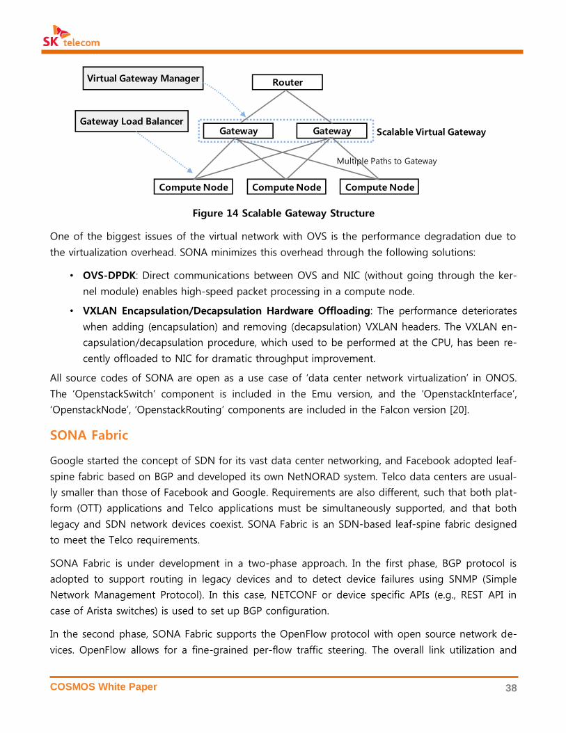
COSMOS White Paper 38
Figure 14 Scalable Gateway Structure
One of the biggest issues of the virtual network with OVS is the performance degradation due to
the virtualization overhead. SONA minimizes this overhead through the following solutions:
• OVS-DPDK: Direct communications between OVS and NIC (without going through the ker-
nel module) enables high-speed packet processing in a compute node.
• VXLAN Encapsulation/Decapsulation Hardware Offloading: The performance deteriorates
when adding (encapsulation) and removing (decapsulation) VXLAN headers. The VXLAN en-
capsulation/decapsulation procedure, which used to be performed at the CPU, has been re-
cently offloaded to NIC for dramatic throughput improvement.
All source codes of SONA are open as a use case of ‘data center network virtualization’ in ONOS.
The ‘OpenstackSwitch’ component is included in the Emu version, and the ‘OpenstackInterface’,
‘OpenstackNode’, ‘OpenstackRouting’ components are included in the Falcon version [20].
SONA Fabric
Google started the concept of SDN for its vast data center networking, and Facebook adopted leaf-
spine fabric based on BGP and developed its own NetNORAD system. Telco data centers are usual-
ly smaller than those of Facebook and Google. Requirements are also different, such that both plat-
form (OTT) applications and Telco applications must be simultaneously supported, and that both
legacy and SDN network devices coexist. SONA Fabric is an SDN-based leaf-spine fabric designed
to meet the Telco requirements.
SONA Fabric is under development in a two-phase approach. In the first phase, BGP protocol is
adopted to support routing in legacy devices and to detect device failures using SNMP (Simple
Network Management Protocol). In this case, NETCONF or device specific APIs (e.g., REST API in
case of Arista switches) is used to set up BGP configuration.
In the second phase, SONA Fabric supports the OpenFlow protocol with open source network de-
vices. OpenFlow allows for a fine-grained per-flow traffic steering. The overall link utilization and
Compute Node Compute Node Compute Node
Gateway Gateway
Router
Scalable Virtual Gateway
Virtual Gateway Manager
Gateway Load Balancer
Multiple Paths to Gateway

COSMOS White Paper 39
east-west traffic throughput can be improved with OpenFlow as traffic can be load-balanced across
the multiple links by using the link utilization information from SDV. Figure 15 describes the struc-
ture of SONA Fabric.
Figure 15 SONA Fabric Structure
Configuration Automation by OpenConfig
OpenConfig is an open source project led by Google to standardize the configuration API of
switches or routers using the Yang model [21][22]. It defines the data models and APIs that config-
ure BGP (Border Gateway Protocol) and MPLS (Multi-Protocol Label Switching) [24] and it covers
the streaming telemetry that transfers the traffic statistics of switches.
SK telecom, as a member of OpenConfig, plans to apply OpenConfig not only to the legacy switch-
es (e.g., Cisco, Juniper, and Arista switches), but also the open source switches (OCP or white box
switches). OpenConfig requires a software module on the server side for pushing Yang models to
switches, and a software module on the switch side for translating Yang models and configuring
the switching chipset. The network controllers on the server side, such as ONOS or ODL, can be
used, while open network OS, such as OpenSwitch, can be used on the switch side. Also, NETCONF
can be utilized as a transfer protocol to deliver Yang models to switches.
As a use case of OpenConfig, we consider the switch configuration automation and the flow infor-
mation extraction. Switch configuration data is entered through the T-ROS interface in Section 3.4,
which is received by the network controller through the northbound API and transformed into Yang
Spine
Leaf Leaf
Spine
Leaf
SONA Fabric Manager
NETCONFREST OpenFlow
Arista Cisco OpenFlow
Drivers
Protocols
BGP
SNMP& Link Utilization

COSMOS White Paper 40
models. At the switch side, Yang models are pushed to an OpenConfig agent in OpenSwitch OS to
configure the switching chipsets.
This configuration contains the flow statistics, flow information, reporting period, and reporting
server. The device/flow data generated from this configuration is transferred to SDV that processes
visualization data. Finally, 3DV or T-ROI visualizes the network status to the administrators. Figure
16 schematizes the whole processes.
Switch configuration uses the predefined models of OpenConfig, while flow statistics, which is not
defined in OpenConfig, will be newly modeled, contributing upstream to OpenConfig.
Figure 16 Network Configuration Automation using OpenConfig
3.3 All-Flash Scale-Out Storage
Storage systems in a data center are classfied into three types: block, object and file storage
depending on interfaces used by the client host. OpenStack supports these storage types, Cinder
for block storage, Swift for object storage, and Manilla for file storage. At present, as mentioned
before, Ceph is most widely adopted for block storage among diverse commercialized or open
source storage solutions.
A continuous price fall for flash memory has made SSD become increasingly adopted in enterprise
storage systems, for better performance. A Ceph system using SSD, however, hardly improves
performance when HDD is simply replaced by SDD as Ceph itself is designed to run on an HDD
system [26].
OpenConfig AgentOCP
WhiteboxSwitch
OpenConfig SB
BGP ConfigApp
SW ConfigRest API
TROS TROI3DV
SDV
Flow Stats Switch StatsSwitch Config
NetConf
Flow Stats
Switch Stats
NetworkController
BGP modelFlow stats model

COSMOS White Paper 41
Compared to commercial storage products, Ceph does not provide a user-friendly deployment and
management tool for the administators [27]. Also, some advanced storage features are not yet
supported in Ceph, such as data deduplication and compression for improving data effciency and
QoS, which are essential in an SSD-based system.
AF-Ceph (All-Flash Ceph Storage)
In COSMOS, AF-Ceph has been developed to overcome the aforementioned limitations of Ceph for
all-flash storage. It has improved the I/O bottlenecks focusing on the OSD (Objet Storage Daemon),
which receives write requests from clients and stores those on SSDs. Problems associated with I/O
bottlenecks have been analyzed and solved as described in Figure 17.
Figure 17 AF-Ceph Architecture: OSD Write I/O Path
• Improvement in the course of processing I/O requests: Ceph is basically an object-based
storage system, but uses PGs (Placement Groups), which are logical groups of objects for
tracking object placement and object metadata, so as to avoid expensive computation. Each
PG exploits a lock to restrict concurrent access to the PG to guarantee consistency. It is a
coarse-grained locking that degrades the performance, as critical sections are distributed
over OSD and are in contention for getting a lock. This locking system causes an unneces-
sary wait and inefficient resource allocation for an SSD-based storage system. To improve
this latency, AF-Ceph gathers redundant processing codes together and delivers them to the
dedicated thread. It also merges operations from user’s write requests in order to reduce the
number of write requests to the SSD.
• System optimization for all-flash environment: The throttle function component, in prepa-
ration for a burst of requests, is tailored to the HDD medium in place at each system. In AF-
Ceph, these settings have been changed to respond adequately to the SSD medium and
NVRAM (Non-Volatile RAM). The SSD suffers a drop in performance in the event of simulta-
neous read/write requests because metadata also needs read/modify/write operations in the
XFS (SSD)Journal (NVRAM)
Client
OSD
ReplicaOSD
1. Send Write Req. 2. Send Replication
3. Write I/O toJournal
4. UpdateMetadata
5. Write Data
syncfs()every 5 secs
6. ReceiveReplication
Reply
7. Send WriteACK
Metadata
LevelDB xattr
Data
File System Buffers
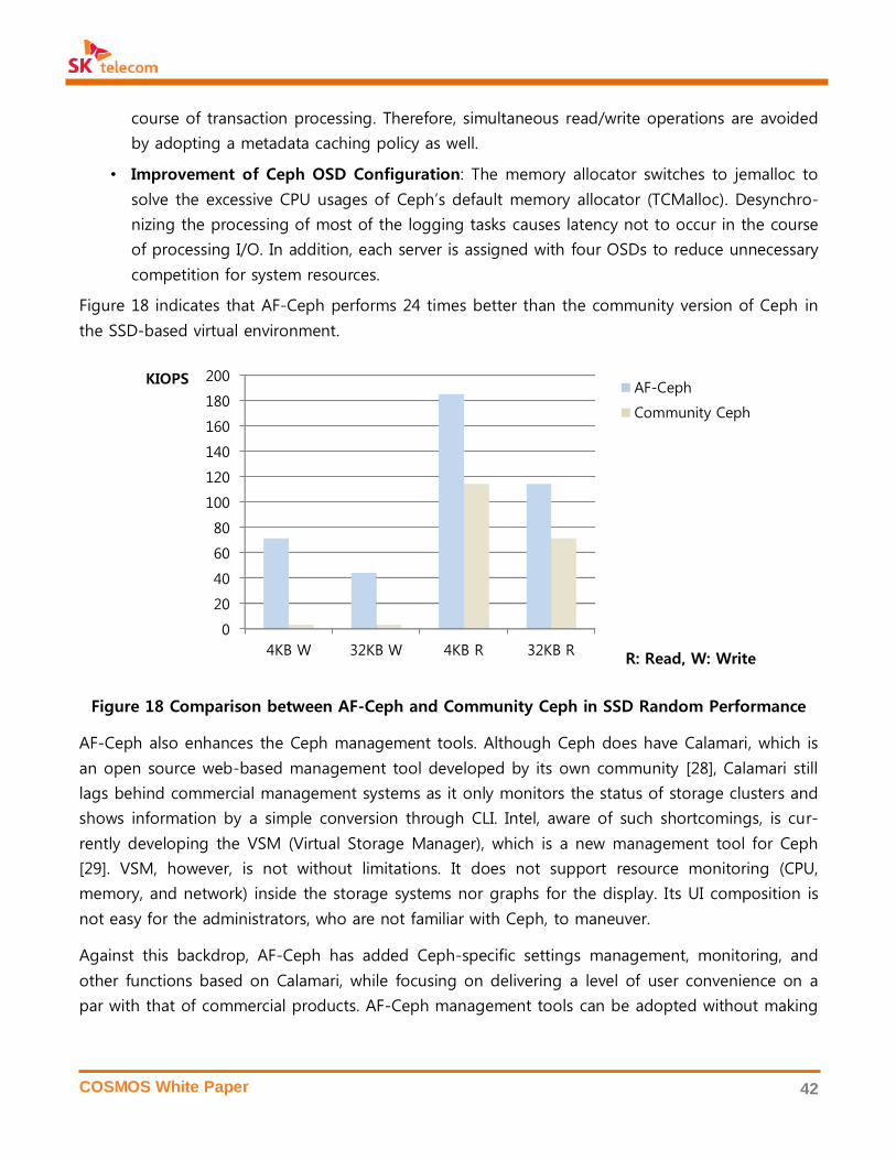
COSMOS White Paper 42
course of transaction processing. Therefore, simultaneous read/write operations are avoided
by adopting a metadata caching policy as well.
• Improvement of Ceph OSD Configuration: The memory allocator switches to jemalloc to
solve the excessive CPU usages of Ceph’s default memory allocator (TCMalloc). Desynchro-
nizing the processing of most of the logging tasks causes latency not to occur in the course
of processing I/O. In addition, each server is assigned with four OSDs to reduce unnecessary
competition for system resources.
Figure 18 indicates that AF-Ceph performs 24 times better than the community version of Ceph in
the SSD-based virtual environment.
Figure 18 Comparison between AF-Ceph and Community Ceph in SSD Random Performance
AF-Ceph also enhances the Ceph management tools. Although Ceph does have Calamari, which is
an open source web-based management tool developed by its own community [28], Calamari still
lags behind commercial management systems as it only monitors the status of storage clusters and
shows information by a simple conversion through CLI. Intel, aware of such shortcomings, is cur-
rently developing the VSM (Virtual Storage Manager), which is a new management tool for Ceph
[29]. VSM, however, is not without limitations. It does not support resource monitoring (CPU,
memory, and network) inside the storage systems nor graphs for the display. Its UI composition is
not easy for the administrators, who are not familiar with Ceph, to maneuver.
Against this backdrop, AF-Ceph has added Ceph-specific settings management, monitoring, and
other functions based on Calamari, while focusing on delivering a level of user convenience on a
par with that of commercial products. AF-Ceph management tools can be adopted without making
0
20
40
60
80
100
120
140
160
180
200
4KB W 32KB W 4KB R 32KB R
KIOPS AF-Ceph
Community Ceph
R: Read, W: Write
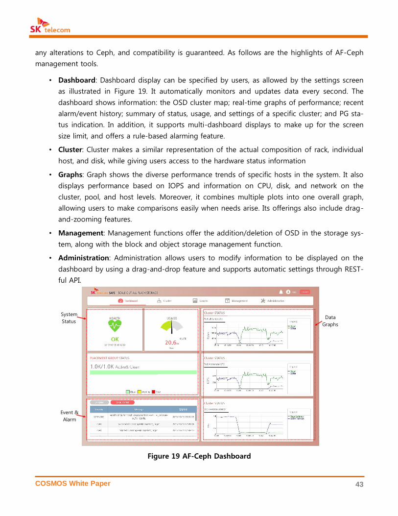
COSMOS White Paper 43
any alterations to Ceph, and compatibility is guaranteed. As follows are the highlights of AF-Ceph
management tools.
• Dashboard: Dashboard display can be specified by users, as allowed by the settings screen
as illustrated in Figure 19. It automatically monitors and updates data every second. The
dashboard shows information: the OSD cluster map; real-time graphs of performance; recent
alarm/event history; summary of status, usage, and settings of a specific cluster; and PG sta-
tus indication. In addition, it supports multi-dashboard displays to make up for the screen
size limit, and offers a rule-based alarming feature.
• Cluster: Cluster makes a similar representation of the actual composition of rack, individual
host, and disk, while giving users access to the hardware status information
• Graphs: Graph shows the diverse performance trends of specific hosts in the system. It also
displays performance based on IOPS and information on CPU, disk, and network on the
cluster, pool, and host levels. Moreover, it combines multiple plots into one overall graph,
allowing users to make comparisons easily when needs arise. Its offerings also include drag-
and-zooming features.
• Management: Management functions offer the addition/deletion of OSD in the storage sys-
tem, along with the block and object storage management function.
• Administration: Administration allows users to modify information to be displayed on the
dashboard by using a drag-and-drop feature and supports automatic settings through REST-
ful API.
Figure 19 AF-Ceph Dashboard
System
Status
Event &
Alarm
Data
Graphs

COSMOS White Paper 44
Next Steps
AF-Ceph has been deployed in Private Cloud 2.0 in Section 5.1 as a high-performance block stor-
age system. It reduces TCO by substituting commercial vendor’s products and improves operation
efficiency by providing advanced management tools.
Until recently, the development of AF-Ceph was focused on identifying and removing the bottle-
necks in Ceph clusters. Going forward, the direction will be towards developing data storage tech-
nologies that will take full advantage of the properties and features of NVRAM and SSD, and also
towards developing the differentiated functions stated below, so that AF-Ceph will have competi-
tiveness on a par with commercial data storage devices. We are also participating in the Ceph
community and contributing our work.
• Data deduplication/compression: This technology is a must-have function for an all-flash
storage to increase SSD endurance and achieve cost savings per GB through an efficient da-
ta storage.
• Guaranteed QoS: Operators can specify the maximum and minimum IOPS to block interfer-
ence that might occur in shared storage devices, and its service guaranteed by entering
SLAs.
• Management tool improvement: Management tools are upgraded to be lightweight and
highly available. A directory-based user management is adopted to ensure compliance with
data center security policy.
• BlueStore: The performance of Ceph can be improved by replacing the existing FileStore
with BlueStore.
3.4 Data Center Automation & Monitoring
In a data center with ten thousand servers, administrators are frequently required to provision OS
and basic software, as the initial deployment takes more than one month and system errors occur
more than once a day. There are various types of gears and vendors, for which different manage-
ment software tools are used. Especially in the SDDC, where additional management software tools
are required for virtual resources as well as physical resources, a significant increase in the time,
effort, and complexity of management results in a slowdown in deployment and a rise in operating
cost.
For this purpose, a data center operation platform (T-ROS) has been developed for COSMOS, which
offers physical/virtual resource management, software/OS provisioning, operation task automation,
maintenance history, asset management, integrated monitoring, and so on.
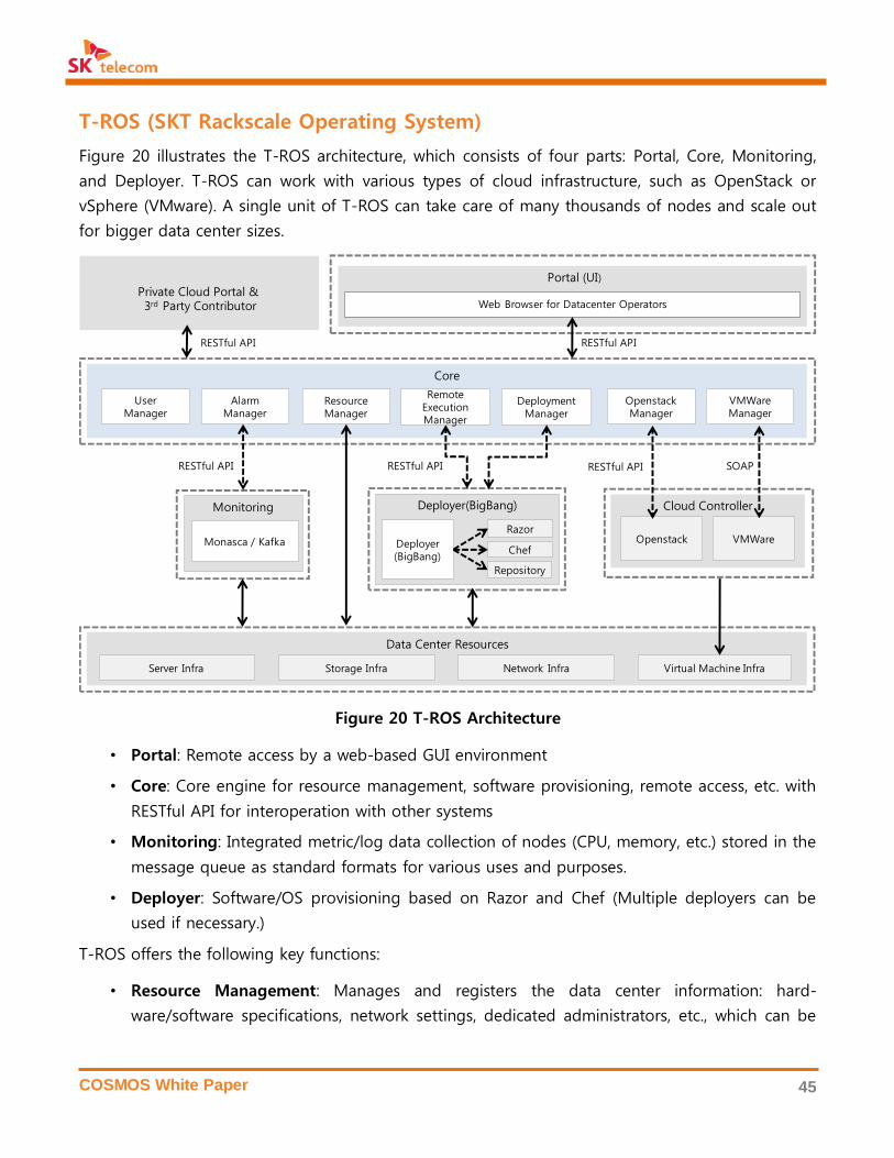
COSMOS White Paper 45
T-ROS (SKT Rackscale Operating System)
Figure 20 illustrates the T-ROS architecture, which consists of four parts: Portal, Core, Monitoring,
and Deployer. T-ROS can work with various types of cloud infrastructure, such as OpenStack or
vSphere (VMware). A single unit of T-ROS can take care of many thousands of nodes and scale out
for bigger data center sizes.
Figure 20 T-ROS Architecture
• Portal: Remote access by a web-based GUI environment
• Core: Core engine for resource management, software provisioning, remote access, etc. with
RESTful API for interoperation with other systems
• Monitoring: Integrated metric/log data collection of nodes (CPU, memory, etc.) stored in the
message queue as standard formats for various uses and purposes.
• Deployer: Software/OS provisioning based on Razor and Chef (Multiple deployers can be
used if necessary.)
T-ROS offers the following key functions:
• Resource Management: Manages and registers the data center information: hard-
ware/software specifications, network settings, dedicated administrators, etc., which can be
Data Center Resources
Server Infra Storage Infra Network Infra Virtual Machine Infra
Core
Portal (UI)
Web Browser for Datacenter Operators
Deployer(BigBang)
Deployer(BigBang)
Chef
Razor
Repository
RESTful API
OpenstackManager
Resource Manager
VMWareManager
Alarm Manager
UserManager
Remote Execution Manager
DeploymentManager
SOAP
Cloud Controller
Openstack VMWare
RESTful API
Private Cloud Portal & 3rd Party Contributor
Monitoring
Monasca / Kafka
RESTful API RESTful APIRESTful API

COSMOS White Paper 46
conveniently entered by batch processing, and automatically collected to minimize manual
manipulation.
• Software Provisioning: Automates OS and software installation for new/malfunctioning
hardware or software upgrades.
• Remote Execution: Executes batch processing of data center operations: password change,
security patch, etc.
• Maintenance history: Records the history of hardware maintenance or replacement: in-
stalling more memory, storage replacement, etc.
• Integrated monitoring: Collects Log/metric data (resource usage, load, etc.) from nodes and
notifies alerts with the critical point setups.
Operation Automation
Operation automation by T-ROS can reduce the operation time by more than 60%, so that one
administrator can handle more nodes with a given time and human error can be also minimized. T-
ROS supports the management of multiple data centers from a centralized remote access point.
OpenStack’s management tool for virtual resource might not satisfy all data center requirements.
For this purpose, administrators can easily understand the overall status and handle the problems
more efficiently with a console for the virtual resource operation in T-ROS by showing relations be-
tween physical and virtual resources, or between services and virtual resources.
The following table summarizes the performance comparison of three bare metal provisioning
methods.
Manual PXE T-ROS
Required
Jobs
Manual installation with CDs
or USB sticks
Remote rebooting and in-
stallation via PXE using IPMI
[30]
One-click installation from
GUI-based dashboard
Running
Time
20-25 minutes per server,
linearly increasing with the
number of servers
(2000-2500 minutes for 100
servers)
20-25 minutes per server by
pipelining processing
(Approximately 500 minutes
for 100 servers)
20-25 minutes for all servers
by parallel processing
(20-25 minutes for 100
servers)
Misc.
Manual settings
(e.g. network setup)
Partial automation using
scripts (manual settings for
network setup)
Full automation without any
operation intervention
Table 3 Comparison of Bare Metal Provisioning

COSMOS White Paper 47
Compared to manual installation, software provisioning can be done in less than 20% of the aver-
age work time, as described in the following table.
Manual T-ROS
Required
Jobs
Direct access to servers to install software
and set up configurations
Remote access and batch job from
the dashboard
Running
Time
Average 15-50 minutes per software Average 5-19 minutes per software
Misc. Human error if not perfectly backed up
with settings for further installation
Automation with identical settings for
further installation.
Table 4 Comparison of Software Provisioning
Integrated Monitoring
In order to provide an integrated monitoring of the physical/virtual resources in COSMOS, T-ROS
uses OpenStack Monasca and Apache Kafka for data collection and storage as illustrated in Figure
21. Monasca agents collect data from physical/virtual servers, which is sent and queued by Kakfa in
T-ROS. This information is used for the data analytics for the operation automation in T-ROS and
for the operation intelligence in T-ROI in Section 3.5. Network flow data is collected by SDV, and
visualized by 3DV as described in Section 3.6.
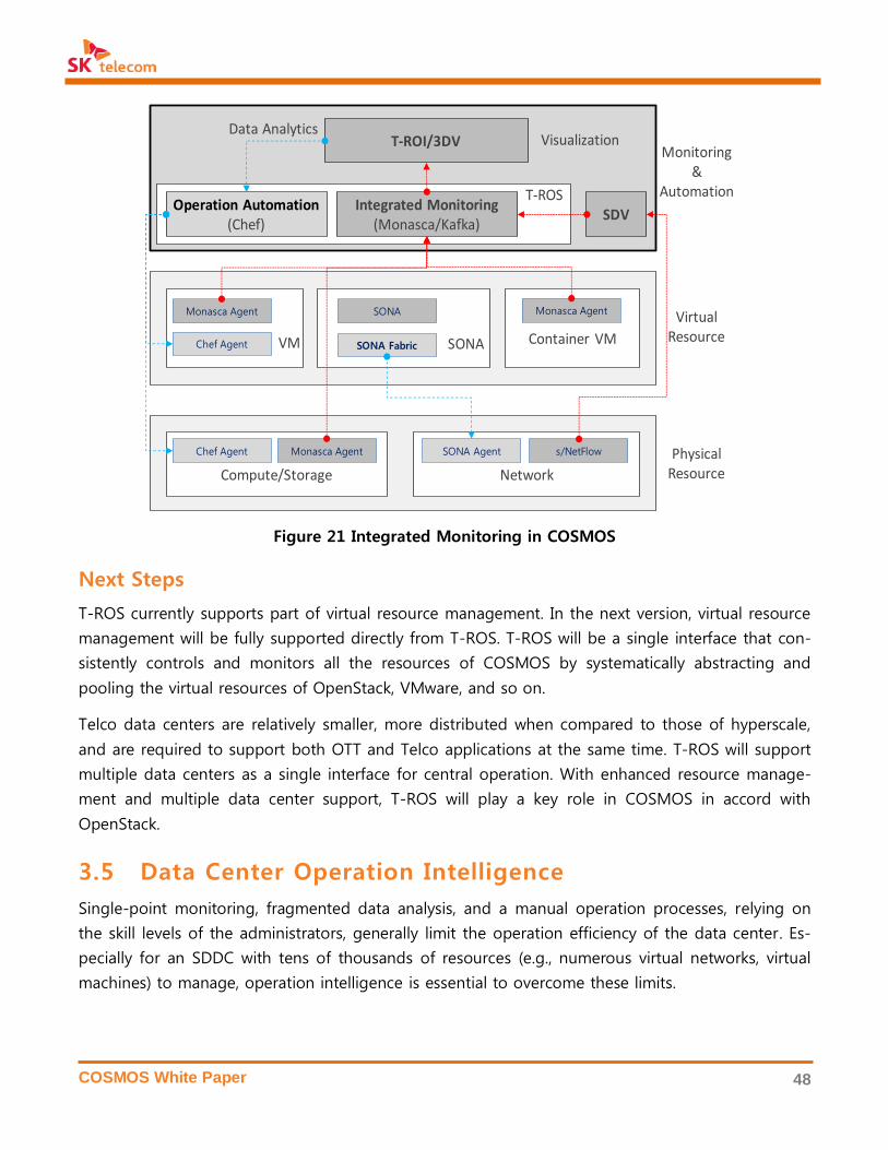
COSMOS White Paper 48
Figure 21 Integrated Monitoring in COSMOS
Next Steps
T-ROS currently supports part of virtual resource management. In the next version, virtual resource
management will be fully supported directly from T-ROS. T-ROS will be a single interface that con-
sistently controls and monitors all the resources of COSMOS by systematically abstracting and
pooling the virtual resources of OpenStack, VMware, and so on.
Telco data centers are relatively smaller, more distributed when compared to those of hyperscale,
and are required to support both OTT and Telco applications at the same time. T-ROS will support
multiple data centers as a single interface for central operation. With enhanced resource manage-
ment and multiple data center support, T-ROS will play a key role in COSMOS in accord with
OpenStack.
3.5 Data Center Operation Intelligence
Single-point monitoring, fragmented data analysis, and a manual operation processes, relying on
the skill levels of the administrators, generally limit the operation efficiency of the data center. Es-
pecially for an SDDC with tens of thousands of resources (e.g., numerous virtual networks, virtual
machines) to manage, operation intelligence is essential to overcome these limits.
Compute/Storage Network
T-ROI/3DV
PhysicalResource
Chef Agent SONA Agent
Container VM
Monasca Agent SONA
s/NetFlowMonasca Agent
VirtualResource
Monasca Agent
SONA Fabric SONA
Operation Automation(Chef)
Integrated Monitoring(Monasca/Kafka)
T-ROS
VisualizationData Analytics
Chef Agent VM
SDV
Monitoring&
Automation

COSMOS White Paper 49
For operational visibility and insight, operation intelligence must provide real-time recommenda-
tions for decision making and failure detection/prediction, which are based on the stream pro-
cessing and the integrated analytics for structured or unstructured machine data generated from
various devices in a data center [31][32][33]. COSMOS implements an operation intelligence system
based on open source software, known as T-ROI.
T-ROI (SKT Rackscale Operation Intelligence)
In general, the operation automation of a data center can be achieved by a two-stage approach.
The first stage automates the process of monitoring and analysis, and the second stage automates
management and control. Monitoring and analysis automation requires a real-time alert system us-
ing algorithm-based models and an anomaly detection system using machine learning or deep
learning. These systems automate the entire process of monitoring and analysis with minimum en-
gagement from administrators.
In COSMOS, T-ROI is a system that supports full automation of monitoring and analysis. T-ROI ana-
lyzes the operation data collected in T-ROS in Section 3.4 and feedbacks its analytical results back
to T-ROS for new configuration or control. For instance, when T-ROI detects an imbalance in virtual
resources for a certain application of COSMOS, T-ROS then directs T-ROI to reallocate the re-
sources to solve the problem of imbalance. In other words, the automation of data center man-
agement and control is maximized through a systematic interaction between T-ROI and T-ROS.
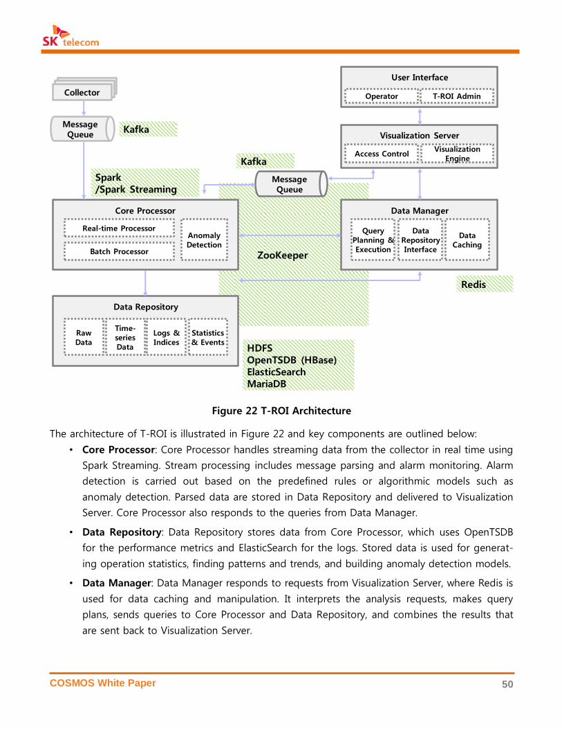
COSMOS White Paper 50
Figure 22 T-ROI Architecture
The architecture of T-ROI is illustrated in Figure 22 and key components are outlined below:
• Core Processor: Core Processor handles streaming data from the collector in real time using
Spark Streaming. Stream processing includes message parsing and alarm monitoring. Alarm
detection is carried out based on the predefined rules or algorithmic models such as
anomaly detection. Parsed data are stored in Data Repository and delivered to Visualization
Server. Core Processor also responds to the queries from Data Manager.
• Data Repository: Data Repository stores data from Core Processor, which uses OpenTSDB
for the performance metrics and ElasticSearch for the logs. Stored data is used for generat-
ing operation statistics, finding patterns and trends, and building anomaly detection models.
• Data Manager: Data Manager responds to requests from Visualization Server, where Redis is
used for data caching and manipulation. It interprets the analysis requests, makes query
plans, sends queries to Core Processor and Data Repository, and combines the results that
are sent back to Visualization Server.
ZooKeeper
Core Processor
Message Queue
수집 Agent수집 AgentCollector
Real-time Processor
Batch Processor
Data Repository
RawData
Time-seriesData
Logs & Indices
Data Manager
Statistics & Events
Visualization Server
AnomalyDetection
Message Queue
Query Planning & Execution
Data Repository Interface
Data Caching
User Interface
Operator T-ROI Admin
Access ControlVisualization
Engine
Spark/Spark Streaming
HDFSOpenTSDB (HBase)ElasticSearchMariaDB
Redis
Kafka
Kafka

COSMOS White Paper 51
• Visualization Server: Visualization Server processes data for user interface and visualization.
It handles the streaming data from Core Processor and the query results from Data Manager
to the user interface. It also executes user authentication and access control.
• User Interface: User Interface is a web-based dashboard for the administrator as explained
below.
User Interface in T-ROI enables administrators to compose their own dashboard and to search data
or statistics as shown in Figure 23. It offers a user-friendly interface for operation diagnosis, failure
cause analysis, and data correlation between resources. In particular, beyond the traditional event
monitoring by setting a simple threshold, T-ROI supports an algorithm-model-based complex event
monitoring, such as search, filtering, aggregation, or group by, etc.
Figure 23 T-ROI User Interface
Next Steps
T-ROI supports anomaly detection by machine learning algorithm, such as multivariate analysis or
deep learning. Anomaly detection can minimizes the intervention of administrators by automatically
detecting the outliers of the operating data. Once T-ROI is applied to commercial sites, the model
for anomaly detection will be continuously elaborated by learning from the operational data, and
the use case of anomaly detection will be specified.
Real-time
Integrated
Analytics
Event
Monitoring
Event
Statistics

COSMOS White Paper 52
Moreover, by interworking with T-ROS, it is possible to automate the overall operation processes:
monitoring, analysis, control, and management. This integration between T-ROS and T-ROI will
greatly improve the level of data center automation.
3.6 Network Monitoring & Visualization
The legacy network management system generally monitors and manages the network devices us-
ing the link-level traffic from SNMP (Simple Network Management Protocol) and the system logs
from the devices. For the SDDC, where the network configuration is complicated compared to the
legacy data center, it is required to visualize multi-layer physical/virtual networks and to monitor
the end-to-end network flow.
In order to provide better network visibility for the SDDC, COSMOS uses an SDV (Software-Defined
Visibility) system to collect additional data, such as SPAN, sFlow, NetFlow, as well as the conven-
tional network data. The collected data are analyzed in real time, and its results are visualized by a
3D user interface to provide a more intuitive view of the whole network by a 3D visualization and
management platform, known as 3DV.
SDV (Software-Defined Visibility)
SDV is a unified solution that collects, analyzes and reports the traffic flow and status of the virtu-
al/physical network devices so as to provide complete network visibility to various monitoring plat-
forms, including 3DV and T-ROI. As illustrated in Figure 24, SDV consists of SNMP collector, flow
analyzer, network packet broker (NPB), and network performance monitor (NPM). Flow analyzer
generates and provides flow information for 3D visualization using sFlow, NetFlow, and packet mir-
roring (SPAN). NPB gathers, filters, and aggregates a specific traffic flow, which is redistributed to
the monitoring tools. NPM analyzes packet-level statistics, TCP performance, and elephants & mice
flows in order to deliver flow information to SONA Fabric for the purpose of the traffic engineering
and to 3DV for the purpose of the fine-grained monitoring.
Commercial hardware products for the SPAN-based flow generator and NPB are currently available,
but expensive. In contrast, SDV is designed as a software system running on any commodity server.
T-CAP in Section 4.5 is an ideal hardware to implement SDV. SDV collects network traffic infor-
mation in the switch part of T-CAP, and runs packet processing and applications on the server part
of T-CAP using DPDK and multi-core processing.
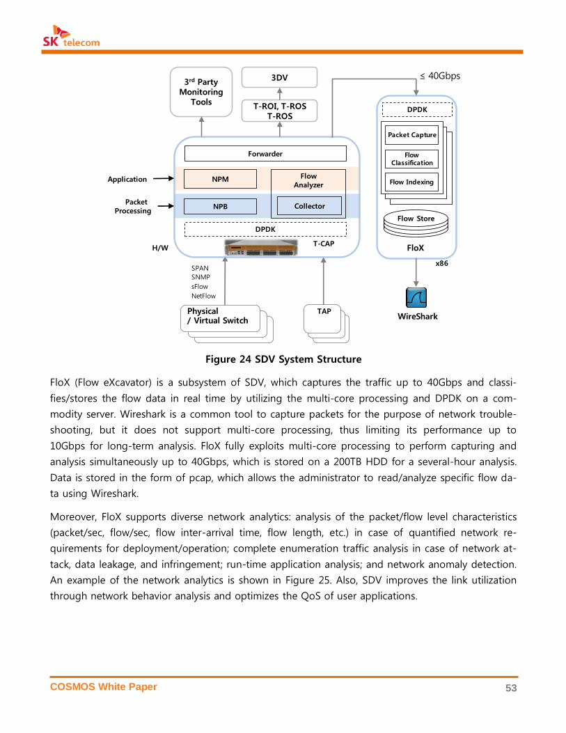
COSMOS White Paper 53
Figure 24 SDV System Structure
FloX (Flow eXcavator) is a subsystem of SDV, which captures the traffic up to 40Gbps and classi-
fies/stores the flow data in real time by utilizing the multi-core processing and DPDK on a com-
modity server. Wireshark is a common tool to capture packets for the purpose of network trouble-
shooting, but it does not support multi-core processing, thus limiting its performance up to
10Gbps for long-term analysis. FloX fully exploits multi-core processing to perform capturing and
analysis simultaneously up to 40Gbps, which is stored on a 200TB HDD for a several-hour analysis.
Data is stored in the form of pcap, which allows the administrator to read/analyze specific flow da-
ta using Wireshark.
Moreover, FloX supports diverse network analytics: analysis of the packet/flow level characteristics
(packet/sec, flow/sec, flow inter-arrival time, flow length, etc.) in case of quantified network re-
quirements for deployment/operation; complete enumeration traffic analysis in case of network at-
tack, data leakage, and infringement; run-time application analysis; and network anomaly detection.
An example of the network analytics is shown in Figure 25. Also, SDV improves the link utilization
through network behavior analysis and optimizes the QoS of user applications.
TAPTAP
TAP
DPDK
NPB
FlowAnalyzer
Collector
NPM
T-ROI, T-ROST-ROS
3rd PartyMonitoring
Tools
Physical/ Virtual Switch
Application
Packet Processing
3DV
Forwarder
T-CAP
SPAN
SNMP
sFlow
NetFlow
H/W
Flow Store
DPDK
Flow Classification
Packet Capture
Flow Indexing
WireShark
FloX
x86
≤ 40Gbps

COSMOS White Paper 54
Figure 25 Flow-level Traffic Analysis in a Data Center
3DV (3D Network Visualization and Management Platform)
To present the diverse information of the data center network in an intuitive way, including the
complex networks with diverse hierarchies, and the flow information, a novel network management
system based on a topological map has been introduced. Topological map is a method that visual-
izes the connections between network elements. Existing systems use the topological map, but it
falls short of providing sufficient interaction and information as topological maps/charts and device
information are displayed in separate windows. In COSMOS, 3DV (3D network visualization and
management platform) provides topological maps with a sufficient amount of interaction to express
a vast amount of information changing in real time, and utilizes infographics to intuitively deliver
information on a single screen. Moreover, its 3D-based user interface efficiently visualizes the phys-
ical/virtual networks with different hierarchies, and shows the end-to-end flow information in 3D.
As illustrated in Figure 26, the network data collected by SDV is analyzed in various aspects on the
real-time data processing platform of T-ROI. Such an approach makes it possible to detect and
analyze the network devices in real time. In the event of a network failure or a malicious attack,
such as a DDoS (Distributed Denial of Service), administrators can pinpoint and take action on the
flow that induces the problem. Administrators can also better understand the status of networks
intuitively and respond to the events in a prompt manner with the real-time big data analytics.

COSMOS White Paper 55
•
Figure 26 Structure of SDV and 3DV
Figure 27 shows the user interface of 3DV, and the main features are as follows:
• Intuitive, interactive UX by a 3D game engine: 3DV utilizes a 3D game engine based on a
topological map to provide a more interactive, intuitive UX. The interaction provided by the
3D engine is faster and more convenient than that of the existing web. 3DV realizes scalabil-
ity by using game engine’s click and zoom in/out function to control the complexity of in-
formation. The topological map is available from zoom level 0 to 5, and all components
from virtual machines to network devices in a large-scale data center are visualized in a sin-
gle map.
• Intuitive infographics and animations: The 3D game engine offers a stronger infographics
function compared to the existing UI. The infographics support not only the simple images
of the subjects, but animations and state changes, which are frequently employed in games.
3DV leverages this feature to present complex information quickly and clearly through dy-
namic infographics.
• End-to-end network analysis based on flow: 3DV puts the many virtual networks of a
large-scale data center onto a single scene. Moreover, as network information is analyzed at
the flow level, there is a need for a system that analyzes and processes large volumes of in-

COSMOS White Paper 56
formation in real-time. 3DV uses the real-time big data analysis engine of T-ROI to analyze
large volumes of data in real time.
• Diverse monitoring technologies of Telco data centers: The 3DV platform provides not
only existing monitoring and management tools such as SNMP and NETCONF, but also
monitoring technologies, such as sFlow and Netflow, that enable the collection of flow in-
formation. We also offer OpenFlow-based SDN monitoring and management technologies
that are recently and widely used, so that networks can be monitored and managed based
on flow. Technologies that enable administrators to analyze entire packets using mirror or
tap are also offered to support a more accurate analysis of networks.
Figure 27 3DV User Interface
Next Steps
SDV and 3DV currently focus on the visualization and end-to-end monitoring of the data center
network. They will evolve to a comprehensive network control platform, which allows administrators
to control the specific functions of networks. 3DV will allow administrators to control individual flow
as well as the devices, integrated with SONA and T-ROS.
Moreover, SDV and 3DV will extend to Telco mobile/fixed networks to enable data collec-
tion/analysis/visualization in various layers using the real-time big data processing system and 3D
engine.
Data Center
Network
Topology
Status
PanelFlow
Search

COSMOS White Paper 57
4. OPEN SOURCE HARDWARE IN COSMOS
COSMOS is basically comprised of open source hardware, but specialized forms of hardware are
developed to satisfy the requirements of certain applications as illustrated in Figure 28. OCP is con-
sidered a candidate for the standard physical servers, switches, storages, and racks for COSMOS,
which can be deployed as a standalone in the greenfield deployment of a data center, or be mixed
with the legacy 19-inch hardware in existing data centers.
Specialized hardware includes NAND flash, FPGA, GPGPU, etc., to maximize the performance of cer-
tain applications. NVMe SSD and card (NV-Drive), PCIe JBOF (NV-Array), big data processing accel-
erator (DPA PCIe Card), high-performance all-flash media server (AF-Media), and network appliance
(T-CAP) have been developed and deployed for COSMOS.
Next-generation hardware will also be considered, such as Intel Rack Scale Design. For this purpose,
Ericsson’s HDS8000, which was announced to be contributed to OCP, is being tested. Also, for Tel-
co NFV/SDN, the introduction and interoperation with hardware accelerators or specialized devices
is being pursued via the OCP Telco Project.
Figure 28 COSMOS Hardware Architecture
4.1 NVMe SSD & Card
SSD (Solid-State Drive) is widely used in various sectors ranging from consumer markets including
desktop and notebook to hyperscale and traditional enterprise storage systems because of its sig-
Coexistence
21-inch OCP Racks 19-inch Racks
Power Shelf
OCP Switch
T-CAP
NV-Array
Server
OCP Switch
Server
T-CAP
AF-Media
NV-Array
Hadoop Server
NV-Drive
DPA PCIe Card
OCPSpine Switch
OCPSpine Switch
…
…
OCPServer
OCPServer
OCPServer
OCPServer
OCPServer
OCPServer
OCPServer
OCPServer
OCPServer

COSMOS White Paper 58
nificant performance gain over HDD. Due to an innate limitation of HDD that works mechanically,
the market share of HDD has dropped by an annual 20-30% in the consumer market showing an
apparent downward trend. Even in the enterprise market, there is an attempt to change data cen-
ters into all-flash systems going beyond the existing hybrid SSD-HDD storage systems [34]. Accord-
ing to Gartner, drastic market growth is expected for the enterprise SSD market ($5.8B in 2014
growing to $15.4B in 2019), which is estimated to surpass the HDD market ($9.7B in 2014 growing
to $11.5B in 2019) [7]. Nowadays, SSD is mainly used on VDI (Virtual Desktop Infrastructure) and
OLAP (On-Line Analytical Processing), but it is more widely being adopted for media streaming and
cloud computing because its price is getting lower and its performance is getting higher.
Figure 29 An estimate on the market size of enterprise HDD and SSD
An enterprise SSD, in general, is optimized for random I/O performance and requires relatively high
endurance although it may vary depending on applications. Table 5 describes the high-
performance support of the enterprise SSD, which requires new NVMe protocols exploiting the
high-bandwidth PCIe interface.
An enterprise SSD is used across diverse areas and use cases by company and application; and the
world leading hyperscale companies, particularly, by collaborating with SSD manufacturers have
jointly or independently developed their own SSDs optimized for their processing procedures.
Consumer SSD Data Center SSD Enterprise SSD
Performance 100K IOPS 200-800K IOPS ~1M IOPS
Capacity 64-512 GB 400GB-4TB 2TB-16TB
Interface SATA/PCIe SATA/SAS/PCIe SAS/PCIe
Endurance 0.3-0.5 DWPD* 1-5 DWPD 3-20 DWPD

COSMOS White Paper 59
Price $0.3-0.5/GB $1-2/GB $2-5/GB
DWPD (Drive Write Per Day) shows the maximum number of entire-capacity writes per day within the warranty period
Table 5 SSD Performance Comparison
NV-Drive
NV-Drive is a high-performance enterprise SSD developed by SK telecom which aims to deliver a
storage system optimized for various application characteristics of enterprise data centers by using
the recent 3D NAND flash technology introduced by SK hynix. It aims to maximize the competitive-
ness of an all-flash storage system and goes even further to lay the foundation on which an all-
flash based data center can be built.
Figure 30 NV-Drive
NV-Drive exists both in the form of the PCIe card (HHHL) and U.2 (2.5”) suitable for the enterprise
environment with a goal of offering a high-performance, high-capacity SSD that supports PCIe Gen
3.0 by using the SK hynix’s 3D NAND flash as mentioned above and Microsemi’s commercial SSD
controller. The characteristics of NV-Drive are as follows.
• PCIe Gen 3.0 / NVMe 1.2 Standard Protocol: The use of high bandwidth of PCle is the ad-
vantage of using the existing SATA Express but since it uses SATA protocol driven by HDD
with a long latency time, protocol overhead is relatively high and there exist limitations in
fully using the parallelism of flash. NVMe is a new storage protocol that has been intro-
duced to overcome the aforementioned issue which assumes that a storage device is flash-
based. The NVMe specification allows up to 64K individual queues, thus making it easy to
secure the parallel operation of multiple flash-based storage devices within an SSD. In addi-
tion, as it maintains queues through the core of a CPU, a separate lock operation for I/O
became unnecessary. Due to these various advantages, NVMe SSD is expanding its market
share in the enterprise market and is expected to expand further into the consumer market.
AHCI (SATA) NVMe
[ U.2 (2.5”) Type ] [ Add-In Card (HHHL) Type ]
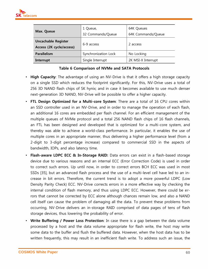
COSMOS White Paper 60
Max. Queue 1 Queue,
32 Commands/Queue
64K Queues
64K Commands/Queue
Uncachable Register
Access (2K cycle/access) 6-9 access 2 access
Parallelism Synchronization Lock No Locking
Interrupt Single Interrupt 2K MSI-X Interrupt
Table 6 Comparison of NVMe and SATA Protocols
• High Capacity: The advantage of using an NV-Drive is that it offers a high storage capacity
on a single SSD which reduces the footprint significantly. For this, NV-Drive uses a total of
256 3D NAND flash chips of SK hynix; and in case it becomes available to use much denser
next-generation 3D NAND, NV-Drive will be possible to offer a higher capacity.
• FTL Design Optimized for a Multi-core System: There are a total of 16 CPU cores within
an SSD controller used in an NV-Drive, and in order to manage the operation of each flash,
an additional 16 cores are embedded per flash channel. For an efficient management of the
multiple queues of NVMe protocol and a total 256 NAND flash chips of 16 flash channels,
an FTL has been designed and developed that is optimized for a multi-core system, and
thereby was able to achieve a world-class performance. In particular, it enables the use of
multiple cores in an appropriate manner, thus delivering a higher performance level (from a
2-digit to 3-digit percentage increase) compared to commercial SSD in the aspects of
bandwidth, IOPs, and also latency time.
• Flash-aware LDPC ECC & In-Storage RAID: Data errors can exist in a flash-based storage
device due to various reasons and an internal ECC (Error Correction Code) is used in order
to correct such errors. Up until now, in order to correct errors BCH ECC was used in most
SSDs [35], but an advanced flash process and the use of a multi-level cell have led to an in-
crease in bit errors. Therefore, the current trend is to adopt a more powerful LDPC (Low
Density Parity Check) ECC. NV-Drive corrects errors in a more effective way by checking the
internal condition of flash memory, and thus using LDPC ECC. However, there could be er-
rors that cannot be corrected by ECC alone although chances remain low, and also a NAND
cell itself can cause the problem of damaging all the data. To prevent these problems from
occurring, NV-Drive delivers an in-storage RAID comprised of data pages of tens of flash
storage devices, thus lowering the probability of error.
• Write Buffering / Power Loss Protection: In case there is a gap between the data volume
processed by a host and the data volume appropriate for flash write, the host may write
some data to the buffer and flush the buffered data. However, when the host data has to be
written frequently, this may result in an inefficient flash write. To address such an issue, the
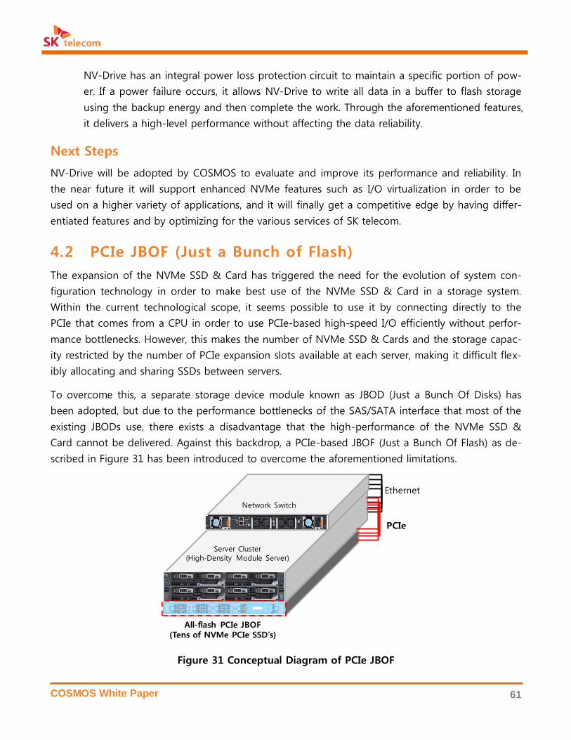
COSMOS White Paper 61
NV-Drive has an integral power loss protection circuit to maintain a specific portion of pow-
er. If a power failure occurs, it allows NV-Drive to write all data in a buffer to flash storage
using the backup energy and then complete the work. Through the aforementioned features,
it delivers a high-level performance without affecting the data reliability.
Next Steps
NV-Drive will be adopted by COSMOS to evaluate and improve its performance and reliability. In
the near future it will support enhanced NVMe features such as I/O virtualization in order to be
used on a higher variety of applications, and it will finally get a competitive edge by having differ-
entiated features and by optimizing for the various services of SK telecom.
4.2 PCIe JBOF (Just a Bunch of Flash)
The expansion of the NVMe SSD & Card has triggered the need for the evolution of system con-
figuration technology in order to make best use of the NVMe SSD & Card in a storage system.
Within the current technological scope, it seems possible to use it by connecting directly to the
PCIe that comes from a CPU in order to use PCIe-based high-speed I/O efficiently without perfor-
mance bottlenecks. However, this makes the number of NVMe SSD & Cards and the storage capac-
ity restricted by the number of PCIe expansion slots available at each server, making it difficult flex-
ibly allocating and sharing SSDs between servers.
To overcome this, a separate storage device module known as JBOD (Just a Bunch Of Disks) has
been adopted, but due to the performance bottlenecks of the SAS/SATA interface that most of the
existing JBODs use, there exists a disadvantage that the high-performance of the NVMe SSD &
Card cannot be delivered. Against this backdrop, a PCIe-based JBOF (Just a Bunch Of Flash) as de-
scribed in Figure 31 has been introduced to overcome the aforementioned limitations.
Figure 31 Conceptual Diagram of PCIe JBOF
All-flash PCIe JBOF(Tens of NVMe PCIe SSD’s)
Server Cluster(High-Density Module Server)
Network Switch
Ethernet
PCIe

COSMOS White Paper 62
PCIe-based JBOF can be defined as ‘a storage device module with multiple NVMe SSDs mounted in
high-density to offer storage space for several servers via a high-performance PCle interface.’ The
most distinctive feature of JBOF is high performance with a direct PCIe link between the CPU and
the NVMe by PCIe switching, eliminating bottlenecks caused by the protocol conversion of
SAS/SATA.
Moreover, in contrast to an integral type where an SSD is installed on the extension slots within a
server, it supports a disaggregated architecture that allows flexible resource allocation by adjusting
ratios between compute and storage resources. This serves as a critical factor in designing SSD
hardware since traditional all-in-one hardware is not capable of meeting the various ratio require-
ments between CPU and storage, which are defined by the applications in data centers. This archi-
tecture allows resource sharing and pooling in a significantly effective way, thus enabling optimal
resource utilization.
Due to the advantages that PCIe JBOF carries, many major vendors have embarked on the devel-
opment of PCle-based all-flash storage solutions and the well-known cases are as follows:
Vendor Key Trends
SanDisk Launched SAS I/F-based JBOF product
(InfiniFlash, 512TB/3U, 0.78MIOPS)
Samsung Announced SAS & PCIe I/F-based JBOF Reference System
in 2015 Flash Memory Summit (48TB/2U, 2.3MIOPS)
Facebook PCIe JBOF development to eliminate SAS interface bottlenecks underway
(Lightning, 120TB/2U, 4.4MIOPS)
EMC Launched DSSD, an NVMe PCIe flash-based storage device system
(144TB/5U, 10MIOPS)
Table 7 PCIe JBOF Products by Major Vendors
PCIe Switching Technology: PCIe switching is essential in JBOF, which connects storage and compute
nodes via the high-speed PCIe interface. The PCle interface is limited in offering only a point-to-point in-
terconnection. PCIe switching overcomes this limit by extending a single (physical) port to multiple logical
PCle ports via software and by offering an effective interconnection between both physical and logical
ports.
This technology is currently at the level of supporting virtual partitioning (similar to VLAN in network
switching), which allows the use of one physical PCle switch as multiple separate switches. Being backed
by port virtualization to share a single PCIe port, however, sophisticated switching technologies including
SR-IOV (Single Root Input Output Virtualization) or Multi-Root IOV have emerged in the market at the
initial level of commercialization. In addition, given the growing attention to the potential possibility of
connecting host servers using high-speed links through PCle in a rack-scale framework, the importance of
PCle switching technology is expected to grow continuously.

COSMOS White Paper 63
NV-Array
To build a large-volume and high-speed storage system that is deemed essential for an SDDC to
deliver low-latency high-volume services in the 5G era, SK telecom is developing NV-Array, a PCIe
JBOF, as described in Figure 32. NV-Array is a storage device with the highest level of density using
the NVMe SSD. It also offers high performance and high reliability, which are essential factors in
enterprise IT services, through its internal redundancy configuration. The key features of NV-Array
are as followed:
• High-speed I/O performance: Supports up to a 6.6M IOPS I/O performance through PCIe
3.0-based NVMe SSD installation, which minimizes interface bottlenecks.
• Highest level of density: Supports 20 x 2.5” NVMe SSD per 1U, low-level capacity of
80TB(4TB/SSD)
• Maximized reliability: Offers high availability through PCIe switching chipset with dual
mode/board mode.
• Hot-swap SSD replacement: Supports SSD replacement during operation
Figure 32 NV-Array
To realize NV-Array, various technologies are being developed as follows:
NV-Array
Architecture Design
Definition of key requirements for various applications
Design of up/down ports and PCI lane
High Availability
for PCIe Switching Hardware architecture and switch firmware for high availability
High-speed Low-noise
PCIe Switch Board Low-noise PCIe 3.0 switch board for high-speed/multi-port/multi-line
SSD Hot-Swap
U.2 2.5 InchNVMe SSD (20x)
COSMOS White Paper 64
High-density, High-efficiency
Apparatus Design
Apparatus design for optimal heat emission
Apparatus design for easy SSD swapping during operation
Host Driver/
GUI Software
Software driver and GUI on the operating system of the hosts that
monitors and changes SSD allocation
Open BMC Open BMS that monitors and manages SSD, PCIe switch, and enclo-
sure
Table 8 Technologies of NV-Array
There are many points to be considered at the design stage as it is a novel type of the storage sys-
tem that has not yet existed. For instance, JBOF’s overall architecture must be designed to minimize
the bottleneck effect in the I/O path of a CPU, host PCIe card, PCIe switch, and NVMe SSD. The ar-
chitecture must reflect the flexibility according to the application type, such as the number of hosts
and port configuration.
For high availability, a redundancy configuration of a PCIe switching chipset with automatic
changeover is required. The high-speed digital board must support a high-quality transmis-
sion/reception of the additional signals used for the efficient management of a total of 100 or
more lanes in a high-speed PCIe 3.0 link. Heat emission is an important design factor in a high-
density system with a number of power-consuming NVMe SSDs in a small enclosure. The host de-
vice driver for the entire system operation and PCIe expansion card also need to be newly devel-
oped.
Next Steps
NV-Drive aims to achieve TCO reduction and performance maximization through a high-density,
flexible appliance hardware that has low power and small footprint. This device will be used for
Ceph storage or Hadoop appliance. It will be contributed upstream to OCP, and potential collabo-
rations with ODMs (Original Design Manufacturers) will be pushed ahead. In addition, new technol-
ogies such as NVMe over Fabric are under investigation to continuously upgrade NV-Array.
4.3 All-Flash Data Processing Accelerator (DPA)
In general, the performance of a server cluster depends on three factors: CPU computing power,
network speed, and storage I/O performance. Among the three factors, a recent explosive growth
in data volume has made CPU a major bottleneck in the data processing domain. The growth of
CPU clock frequency with the semiconductor fabrication technology has almost reached its limit,
and the increased number of cores integrated on a silicon die cannot keep up with the require-
ments of big data computation. Moreover, the rapid development of NAND flash technology has
COSMOS White Paper 65
been solving the density and performance problems of HDD-based storage, and thus it becomes
an immediate challenge to make the system fully utilize the performance of SSD.
An accelerator based on a GPGPU (General Purpose Graphics Processing Unit) or FPGA (Field Pro-
gramming Gate Array) is known as an effective solution to make up for the CPU’s computing power
limitation. GPGPU has a specialized architecture for the tasks of MPP (Massively Parallel Processing)
– that is, a sequence of operations for a large amount of independent data is accelerated with a
number of small symmetric cores working with the same sequence of instructions. Recently a GPG-
PU integrating thousands of the simple cores is widely used for accelerating big data analytics and
machine learning including Deep Learning. GPGPU is, however, not applicable if a task does not
suit MPP in its processing structure, that is, there is dependency in data processing or the execu-
tion sequence of the processing is complex due to branches.
On the other hand, FPGA is a kind of reprogrammable hardware that emulates hard-wired digital
logic. This technology is located between hardware implementation by ASIC (Application Specific
Integrated Circuit) and software implementation on CPU. FPGA is inherently slower and more power
consuming than ASIC, but faster and more power efficient than CPU. FPGA does not require the
expensive semiconductor fabrication process of ASIC, and it is applicable to any type of applica-
tions designed with digital logic, while GPGPU is limited to the MPP applications. Research has re-
ported that FPGA is more energy efficient than GPGPU even for MPP applications, but its absolute
performance is not yet comparable with GPGPU. Nowadays, FPGA supports heterogeneous pro-
gramming languages such as OpenCL for its logic synthesis to reduce the hardware development
time.
DPA PCIe Card
DPA is a FPGA PCIe card that accelerates the data processing by offloading a data processing or
computing-intensive workload from CPU. It is a cost-efficient solution that reduces infrastructure
investment, power consumption, and footprint as opposed to scaling the server cluster to increase
the computing power. DPA, installed on a PCIe slot of a server, resolves the CPU computing bottle-
neck by fully utilizing the enhanced I/O performance of SSD.
OpenCL (Open Computing Language) is a standard of writing parallel program that is executed across
heterogeneous platforms. It is widely used for GPGPU programming for high-performance computing
since it is designed to be suitable for GPU with SIMT (Single Instruction Multiple Thread) architecture. Ma-
jor FPGA vendors like Xilinx and Altera (now a subsidiary of Intel) also support OpenCL for hardware pro-
gramming to increase productivity.

COSMOS White Paper 66
Figure 33 FPGA-based DPA PCIe Card
Initial use cases of DPA are twofold:
• Big Data Analytics Cluster: Unlike traditional RDBMS appliances, a big data cluster is usually
composed of commodity servers and Hadoop-based open source software in order to min-
imize cost. Instead of separating storage architecture, compute nodes are merged with stor-
age nodes with a distributed file system. An SSD-HDD hybrid system enhances the data
bandwidth towards CPU over 2Gbps or 4Gbps by exploiting NVMe SSD. A CPU’s data pro-
cessing capability, however, hardly exceeds 1Gbps for most analytics workloads with a num-
ber of four or less Xeon CPUs per node.
DPA can overcome this data processing limit by offloading highly computational tasks such
as data compression/decompression and SQL query computation. DPA can accelerate the
gzip-based compression/decompression and data filtering of SQL several times faster than
CPU. Data mining and machine learning are also tasks that require heavy computation. DPA
can accelerate many machine learning algorithms in Spark-ML.
• Storage Cluster: CPU creates a bottleneck in a high-performance storage system particularly
as the storage density gets higher and the throughput goes up by using SSD. Data reduc-
tion technologies, such as compression, deduplication, and erasure coding, are crucial for an
SSD-based storage to minimize the use of relatively expensive NAND flash. Data reduction
processing creates additional computation-intensive workloads. For instance, if an applica-
tion fully utilizes an SSD-based storage system with four servers with 200k IOPS per server,
the total storage bandwidth reaches 800k IOPS, while the CPU’s performance is limited to
200k IOPS for random write.
Data compression/decompression and block-level inline deduplication are the bottlenecks,
and DPA can solve this problem and fully utilize SSD’s I/O bandwidth as well.

COSMOS White Paper 67
Next Steps
The communication overhead between CPU and accelerator is the most critical performance issue
of an accelerator, including DPA, because an accelerator spends most of its time reading input data
and writing output data from/to CPU cache or system main memory. It is possible to mitigate the
communication overhead to some degree by hardware or software technologies such as DMAC (Di-
rect Memory Access Control), mmap (memory-mapped file I/O), user-level device access, and zero-
copy data transfer.
These technologies, however, are not comprehensive; and there still remain problems such as lim-
ited PCIe latency and bandwidth, data incoherence between CPU and accelerator caches, difficulty
in accessing virtual memory space, etc. A workload that requires frequent interactions with CPU es-
pecially suffers from this communication overhead.
DPA approaches this problem in two different ways: placing the accelerator closer to storage device
or closer to CPU. The first method is to integrate the accelerator into a storage device, known as
ISP (In-Storage Processing), in which most of data processing takes place at the storage side while
a small set of processed data is sent to CPU.
The second method is to use a new technology such as Intel’s Xeon+FPGA. It is a single chip inte-
grating CPU and FPGA using MCP (Multi-Chip Package), which shortens the latency by half and im-
proves the communication throughput between CPU and FPGA by two times. In other words, fine-
grained function acceleration will be possible by eliminating communication overhead with the di-
rect access of virtual memory space, cache coherency, and user-level API. DPA plans to use
Xeon+FPGA to extend its applications to deep learning, security, network acceleration, and so on.
4.4 All-Flash Media Server
Multimedia services have been explosively growing in the world due to the proliferation of mobile
devices and the spread of 4k UHD (Ultra High Definition) services, which result in a significant in-
crease in data traffic. Multimedia traffic is responsible for the largest portion of global internet traf-
fic, which was 70% in 2015 and expected to increase to 82% in 2020.
Mobile devices and smart televisions are rapidly changing the way of producing and consuming
multimedia content. In the set-top-box environment on the wired network, users downloaded mul-
Xeon+FPGA is an Intel’s next generation enterprise CPU that integrates Xeon Skylake and Arria FPGA with
a single package, commercially available in 2017, after Intel merged Altera, a major FPGA company, in
2015. It will reduce the communication latency by one half, increase the bandwidth of it twice, and sup-
port cache coherent access.

COSMOS White Paper 68
timedia content in the past, but nowadays users play the content over the network in real time
from streaming servers. In order to support the large volume of streaming multimedia, multimedia
infrastructure needs to evolve to accept new technologies such as all-flash media servers.
Multimedia service providers have used conventional storage systems for storing and serving mul-
timedia content. This traditional storage system consists of HDD devices with a redundancy config-
uration to satisfy high availability. Along with a performance limit by HDD, there exist additional
factors of degradation such as an I/O performance bottleneck when transmitting data from the de-
vice. As the streaming data significantly grows, the traditional system requires a storage controller
such as HBA that manages additional HDDs, thus increasing the hardware failure ratio and the
hardware cost.
Adopting SSDs is one of the solutions to enhance multimedia services. A multimedia streaming sys-
tem with SSDs provides a high-speed I/O performance and a fast data search time when randomly
accessing the content. SSD also makes the hardware more lightweight and compact. Thus, exploit-
ing SSDs can improve server capacity and density at the same time.
AF-Media
AF-Media is an all-flash media server based on SSD technology with the aim of achieving low pow-
er, high density, and maximum I/O performance designed to serve high-resolution multimedia
streaming.
Figure 34 The Exterior of AF-Media (Front/Back)
To develop a service-optimized product, analysis on the requirements for multimedia service pro-
viders was conducted before high-level design and low-power server development. Low-power CPU
(ATOM or Xeon-D) combined with high-speed SSDs and a wideband NIC realizes a powerful all-
flash media streaming server. Removing unnecessary components, such as an HBA card, and con-
verging hardware structure leads to a high-performance, small-footprint, and low-cost system.
AF-Media uses ATOM or Xeon-D for CPU and SATA SSDs or NVMe SSDs for storage devices. It has
two or four nodes in a 2U enclosure, where each node is independent of each other. These options
enable customers to flexibly choose the system that best fits the workload of target applications.
SATA SSD is recommended for a high-capacity service, while the NVMe SSD is more suitable when
a higher I/O is required.
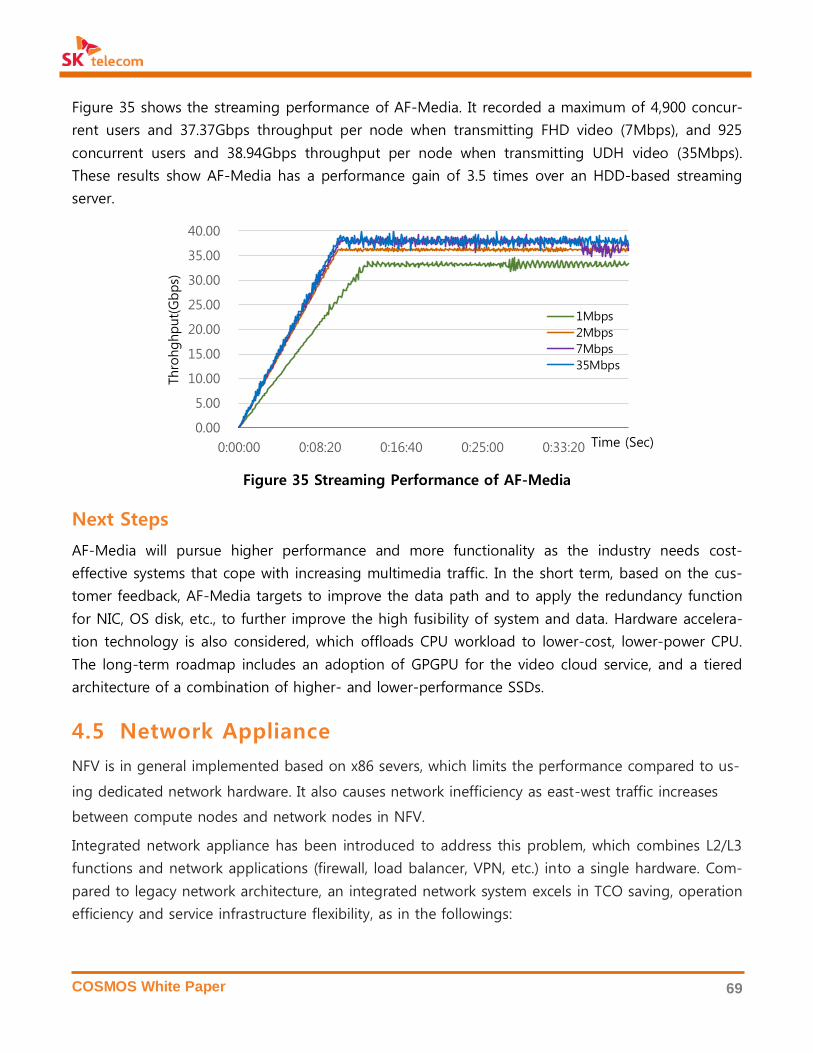
COSMOS White Paper 69
Figure 35 shows the streaming performance of AF-Media. It recorded a maximum of 4,900 concur-
rent users and 37.37Gbps throughput per node when transmitting FHD video (7Mbps), and 925
concurrent users and 38.94Gbps throughput per node when transmitting UDH video (35Mbps).
These results show AF-Media has a performance gain of 3.5 times over an HDD-based streaming
server.
Figure 35 Streaming Performance of AF-Media
Next Steps
AF-Media will pursue higher performance and more functionality as the industry needs cost-
effective systems that cope with increasing multimedia traffic. In the short term, based on the cus-
tomer feedback, AF-Media targets to improve the data path and to apply the redundancy function
for NIC, OS disk, etc., to further improve the high fusibility of system and data. Hardware accelera-
tion technology is also considered, which offloads CPU workload to lower-cost, lower-power CPU.
The long-term roadmap includes an adoption of GPGPU for the video cloud service, and a tiered
architecture of a combination of higher- and lower-performance SSDs.
4.5 Network Appliance
NFV is in general implemented based on x86 severs, which limits the performance compared to us-
ing dedicated network hardware. It also causes network inefficiency as east-west traffic increases
between compute nodes and network nodes in NFV.
Integrated network appliance has been introduced to address this problem, which combines L2/L3
functions and network applications (firewall, load balancer, VPN, etc.) into a single hardware. Com-
pared to legacy network architecture, an integrated network system excels in TCO saving, operation
efficiency and service infrastructure flexibility, as in the followings:
0.00
5.00
10.00
15.00
20.00
25.00
30.00
35.00
40.00
0:00:00 0:08:20 0:16:40 0:25:00 0:33:20
Thro
hghput(Gbps)
Time (Sec)
1Mbps
2Mbps
7Mbps
35Mbps
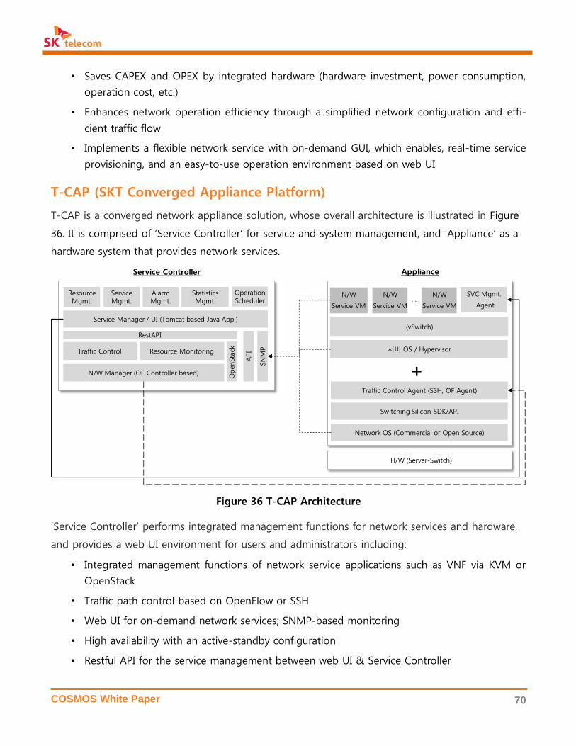
COSMOS White Paper 70
• Saves CAPEX and OPEX by integrated hardware (hardware investment, power consumption,
operation cost, etc.)
• Enhances network operation efficiency through a simplified network configuration and effi-
cient traffic flow
• Implements a flexible network service with on-demand GUI, which enables, real-time service
provisioning, and an easy-to-use operation environment based on web UI
T-CAP (SKT Converged Appliance Platform)
T-CAP is a converged network appliance solution, whose overall architecture is illustrated in Figure
36. It is comprised of ‘Service Controller’ for service and system management, and ‘Appliance’ as a
hardware system that provides network services.
Figure 36 T-CAP Architecture
‘Service Controller’ performs integrated management functions for network services and hardware,
and provides a web UI environment for users and administrators including:
• Integrated management functions of network service applications such as VNF via KVM or
OpenStack
• Traffic path control based on OpenFlow or SSH
• Web UI for on-demand network services; SNMP-based monitoring
• High availability with an active-standby configuration
• Restful API for the service management between web UI & Service Controller
Service Controller
N/W Manager (OF Controller based)
Service Manager / UI (Tomcat based Java App.)
Traffic Control Resource Monitoring
Resource Mgmt.
Service Mgmt.
Statistics Mgmt.
Alarm Mgmt.
RestAPI
SN
MP
API
OpenSta
ck
OperationScheduler
(vSwitch)
N/W
Service VM
SVC Mgmt.
Agent
서버 OS / Hypervisor
Switching Silicon SDK/API
Network OS (Commercial or Open Source)
Traffic Control Agent (SSH, OF Agent)
N/W
Service VM
N/W
Service VM…
+
Appliance
H/W (Server-Switch)
COSMOS White Paper 71
T-CAP is a new type of network hardware that combines a network switch for transmitting the net-
work traffic and a high-performance server for running network applications. It supports the basic
network functions of a legacy switch, such as L2 switching, L3 routing, NAT, DHCP; and it runs vir-
tualized network/security functions, such as L4/L7 load balancing, firewall, VPN, and IDS/IPS. In ad-
dition, other applications can be loaded on its internal storage, including network traffic analysis,
data backup, etc.
T-CAP was first introduced in 2015 based on a modular architecture. In terms of hardware, it is de-
signed to meet diverse service requirements with detachable network interface modules, 10Gpbs or
40Gbps Ethernet interfaces, 4x 2.5-inch SATA SSD/HDDs, and 2x PCIe Gen3 slots. The architecture
physically separates CPU (compute node) for running network applications and CPU (switch node)
for L2/L3 network transport functions to maximize the system reliability, as a failure at each side
would not affect the other.
Due to the unique hardware architecture, OS is also separately installed on the switch/compute
nodes. Compute node supports Linux OS, and will extend its support of OS and hypervisor. Switch
node currently uses network OS based on ZebOS, to provide networking features of a switch or a
router, as it is the network OS that supports diverse switching chipsets and guarantees the stability
of networking functions. Other network OSs will also be supported in the future.
Figure 37 and Figure 38 show the hardware architecture and the physical layout of T-CAP, respec-
tively. Key specifications are as follows:
• 2U size, 19-inch rack mount
• Dual Xeon E5-2600 v3 CPU (Haswell-EP) for compute node
• Intel RRC (Red Rock Canyon) for switch node
• Switching ports at the front panel (12 10Gbps ports / 4 10Gbps ports & 2 40Gbps ports)
• 4x hot-swap bay for 2.5inch SATA HDD/SSD (max 4EA) at the front panel
• 2x PCIe Gen3 slots at the back panel (for HBA card, RAID card, Flash accelerator, and so on)
• 1+1 redundancy power supply units
• Optimized airflow design for cooling (air holes at both sides & airflow guide for CPU cooling)

COSMOS White Paper 72
Figure 37 T-CAP Hardware Architecture
Figure 38 T-CAP Physical Layout
Next Steps
T-CAP is being tested and applied to various network service domains, including L4/L7 network
services. Open source network OS will be mounted and additional hardware extension will be ap-
plied as well.
Application • Additional network applications: monitoring, network analytics, SD-WAN, and

COSMOS White Paper 73
Extension so on in collaboration with 3rd-party application vendors
• Use cases with 3rd-party solutions
- T-CAP with AF-Ceph (e.g., management node, NV-Array)
- T-CAP with virtualization solutions (e.g. VMware NSX edge gateway)
Hardware
Extension
• Open source network OS installation (e.g., OpenSwitch)
• Support for additional switching silicon chipsets
• Hardware acceleration (e.g., FPGA-based NIC, PCIe Flash Accelerator)
Table 9 T-CAP Roadmap

COSMOS White Paper 74
5. CLOUD SERVICES IN COSMOS
COSMOS provides a cloud-based DevOps environment for the internal/external users to develop
and operate diverse applications as illustrated in Figure 39. Private Cloud 2.0 and T-Fabric are the
solutions for IaaS (Infrastructure-as-a-Service) and PaaS (Platform-as-a-Service), respectively. Cur-
rently, the platform (OTT) services are the main target of Private Cloud 2.0 and T-Fabric, but it will
be extended to Telco services and enterprise IT services going forward.
Private Cloud 2.0 is a self-service virtual machine service based on OpenStack, which replaces the
older version that provisioned virtual resources through technical assistants. Private Cloud 2.0 in-
terworks with other systems of SK telecom in order to abide by the IT policy and process of SK tel-
ecom. Therefore, Private Cloud 2.0’s users can save time and effort by using the preinstalled envi-
ronment.
T-Fabric, on the other hand, is an application development/operation platform built on Cloud
Foundry. It uses Docker to support container technology on which each application is running. T-
Fabric manages the application lifecycle, so that users can code, build, test, deploy, operate, and
monitor the applications in a systematic way.
Figure 39 Cloud Services in COSMOS
5.1 Virtual Machine Platform (IaaS)
IaaS enables users to conveniently provision IT resources for application development/operation
without any hardware procurement or deployment by themselves. Users can start services or use
COSMOS
Private Cloud 2.0 (IaaS)
Self-ServicePortal
Fast,RepeatableProvisioning
One-viewDashboard
Operation(Policy,
Billing, …)
T-Fabric (PaaS)
PaaS Engine(App
Life Cycle)
DataBaseService
Source ControlManagement
Web Portal
Platform Service Telco Service Enterprise Service

COSMOS White Paper 75
computing just by submitting specifications for the IT resources they need. IaaS has changed the
way to consume IT resources by cloud computing in order to catch up with rapidly changing IT
technologies and mobile markets. Efficient management of virtual resources in terms of agility and
cost has become important, and enterprises are paying attention to the private cloud as a way to
provision and change resources efficiently and quickly.
Generally, each enterprise has its own policy for IT resource. This policy must be reflected when de-
signing and deploying a private cloud. In SK telecom, there exist diverse systems to support access
control/history, data storage verification, etc., which are sometimes forced by the relevant laws such
as the Information Communication Network Act. These systems have application/permission pro-
cesses consisting of complex, mutually depending stages. Private cloud must interwork with these
existing systems.
Private Cloud 2.0
Private Cloud 2.0 is a new way to provide IaaS in SK telecom, which exploits the virtual resources of
SDC, SDS, and SND in COSMOS. In contrast to the previous version of Private Cloud, where tech-
nical staffs are in charge of provisioning virtual machine services upon a request, Private Cloud 2.0
is a self-service, self-provisioning platform, where users can create, control, and manage the virtual
resources by themselves. It is different from general IaaS services in that all virtual resources abide
by the internal policies and processes of SK telecom.
Features for cloud service administrators are as follows:
• One-View Dashboard: The dashboard shows the information on the physical/virtual re-
source allocation and the available capacity, as illustrated in Figure 40. Service administrator
can check the statistics for utilization efficiency, which are used for deciding on the further
establishment of infrastructure. It also provides alarms or the status of system failures.
• Operation Policy: Service administrators set up all sorts of authority for users or projects
and control the resource quota. Flexible settings are supported by activating diverse func-
tions.
• Metering & Billing: Resource usage data is collected for billing. CAPEX and OPEX are auto-
matically calculated based on the billing rules that can be easily defined, which are notified
to users.

COSMOS White Paper 76
Figure 40 Dashboard of Private Cloud 2.0
Features for the user are as follows:
• Self-Service Provisioning: Users can create and control virtual resources per project simply
by web interface. A friendly guide enables users, who are unfamiliar with IT systems, to easi-
ly create virtual resources.
• Fast & Repeatable Provisioning: Standard templates for typical virtual resource settings are
provided to save time and effort. These templates are already optimized and proven for the
internal environment of SK telecom. Users can also define and share their own templates, so
that others can use verified templates for similar services.
• One-View Dashboard: Users monitor the status and performance of virtual machines per
project in a one-view dashboard. One can add or delete virtual resources, and monitor sys-
tem status through interactive charts.
Finally, features for the data center administrator are as follows:
• Integrated Logs: A comprehensive view on system logs helps operate Private Cloud 2.0.
Monitoring
Resource
Info
Job
History

COSMOS White Paper 77
• Failure Response: A real-time monitoring on virtual/physical machines provides a multidi-
mensional view on system failure for fast recovery support. All necessary recovery actions in-
cluding service migration can be done on a single interface.
• Settings for Interworking Resource: Private Cloud 2.0 provides APIs to set up interworking
physical resources (L4 switch, Firewall, NAS, etc.) on a web user interface.
Private Cloud 2.0, now using the OpenStack Liberty version, is designed and developed to support
the following:
• Open Source Software: Private Cloud 2.0 recommends open source software rather than
commercial software. Virtual machines inherit the software licenses from their physical ma-
chine for commercial software. For this purpose, a zone concept of OpenStack is used so
that virtual machines in a specific zone can freely use the software license.
• Network Security: Internal and external networks are logically separated to meet the securi-
ty requirements of SK telecom. A redundancy configuration on the physical network guaran-
tees high availability, and the virtual network for each use case is isolated by VLAN and in-
terconnected by a firewall. This network separation helps use the same operation policy and
lowers the barrier to introduce a new system.
• Interworking with Internal Systems: A separate network for interworking with internal sys-
tems is used, which is distinguished from the outbound network. Each virtual network for in-
ternal systems meets the corresponding security requirements.
• High Availability: Redundancy configuration on server, network, and storage is used for
high availability. The level of high availability is defined by SLA on the operation zone in
contrast to the development zone.
• High Performance: A variety of virtual machine specifications can be selected depending on
the applications, and an SSD-based storage is adopted to meet high-performance require-
ments.
• Service Interface: A web-based portal can control each component of OpenStack, set up
each internal policy, and automate tasks interworking with relevant systems.
Next Steps
Private Cloud 2.0 will be positioned as a standard platform for service development and operation
at SK telecom, so that it enhances the infrastructure utilization and operation reliability as follows:
• Fast provisioning of internal IT resources by self service and standard process
• Preinstalled network functions of load balancer, firewall, and so on.
• On-demand sharing, reconfiguring, and deleting the virtual resources of SDC, SDN, and SDS

COSMOS White Paper 78
• Reliable operation by simplifying complex virtual resource management
Private Cloud 2.0 contributes to saving cost and automating data center operation by using open
source software, such as OpenStack, Ceph, etc. Telco’s virtualized network functions will be tested
and served on Private Cloud 2.0 as a next step.
5.2 DevOps Platform (PaaS)
PaaS is a middleware layer of the cloud architecture and located in the middle of the application
layer (SaaS domain) and the infrastructure layer (IaaS domain) as shown in Figure 41 [36][37]. PaaS
acts as common libraries for the application layer on the top by constructing the software layer on
top of the infrastructure resources, such as OS, network, storage, etc.
Figure 41 PaaS Layers
It is the SaaS developers who are the users of PaaS, which provides a well-defined environment to
develop applications. Therefore, PaaS plays its role as a provider of SaaS applications in the cloud
computing ecosystem [38][39].
PaaS plays a crucial role in realizing DevOps (Development & Operation) as it provides various de-
velopment tools and operation environments as a service [40]. This means that PaaS must accom-
modate diverse, frequently-changing customer needs.
T-Fabric
T-Fabric endows COSMOS with the PaaS functionality that provisions applications and services. It is
built on the basis of Cloud Foundry’s PaaS and designed to support Docker’s container service.
Along with PaaS functionality, diverse tools that allow developers to access Telco technology assets
Hardware Layer (Hardware Abstraction Layer: IaaS)
PaaS Service Layer Pla
tform
as a
Serv
ice
Infrastructure
Run-timeEnvironment
MiddlewareService
Tools
ApplicationDeveloper

COSMOS White Paper 79
are available to the developers in T-Fabric. One example is T-API [41], through which the develop-
ers can easily adopt the Telco services of SMS/MMS, high-precision location services, authentication,
billing, etc. in their applications. Moreover, the developers can use database services instantly,
which range from an intrinsic database provided by Cloud Foundry to a high-performance relation-
al database.
Figure 42 T-Fabric Architecture
T-Fabric is deployed on Private Cloud 2.0 and composed of the PaaS engine, database, monitoring
system and source code management tools as described in Figure 42.
• PaaS engine: PaaS engine is based on Cloud Foundry and Docker. It supports two types of
application deployment: source code deployment and Docker image deployment. Therefore,
developers can deploy applications (source or binary) in cloud development languages or
traditional software languages including C/C++.
• Database: T-Fabric provides two kinds of database: Cloud Foundry’s intrinsic database and
RDBMS (Relational Database Management System) implemented by a service broker. The
former is better suited for general-purpose applications, while the latter is recommended for
performance-sensitive applications.
• Monitoring: T-Fabric uses Zabbix for monitoring the system metrics and cAdvisor for moni-
toring the container metrics [42]. In addition, Pinpoint, which is an open source Java APM
(Application Performance Monitoring) by NAVER, measures the details of the performance of
Java applications and helps the debugging of Java application [43].
Private Cloud 2.0 (IaaS)
Source Code
(Git, Jenkins)
T-Fabric
RDBMS
(Oracle, etc.)
T-API
Monitoring
Developer Portal
T-Fabric Applications
App
App
Management
Cloud Foundry
cAdvisor
Zabbix
Container
Container
Container
Pinpoint(APM)
Data BaseService Broker
CLI
T-API Proxy

COSMOS White Paper 80
• Source Code Management Tool: T-Fabric interworks with T-DE, which is the SCM (Source
Control Management) system of SK telecom, for source code management.
• T-API Proxy: T-API Proxy is a bridge between internal containers and various external Telco
asset systems (SMS/MMS, email, PlayRTC, payment, identification, weather, BaaS, and etc.),
which allows applications running on T-Fabric to invoke T-APIs for Telco technology assets.
• Web Portal: Developers can use the GUI web portal or CLI (Command Line Interface). The
web portal is a component of T-Fabric, and a typical application running on T-Fabric as well.
Figure 43 T-Fabric Web Portal
T-Fabric provides a DevOps environment that systematically manages the application lifecycle: it
creates, starts, stops, and deletes an application for COSMOS. The functions of T-Fabric, such as
management tool, monitoring tool, APM, source code control, etc. are organically connected ac-
cording to the process of development and operation as described in Figure 44.
Next Steps
T-Fabric provides the standardized environment for developing applications at the corporate plat-
form level so that users do not have to spend time building up their own service environment,
which tends to differ from the others in a company. In particular, as SK telecom aims to be a plat-
form company, T-Fabric serves as a key driver for the transformation.
5G will be realized in several years, where NFV will be widely used. This means that Telco functions
will be managed as software applications. As mentioned before, the container technology is well
suited to accommodate the virtualized network functions due to its performance advantage over
Resource
Info
Application
Monitoring
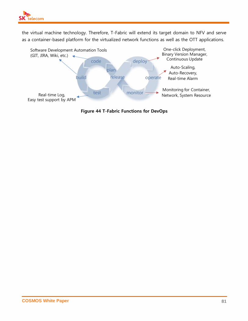
COSMOS White Paper 81
the virtual machine technology. Therefore, T-Fabric will extend its target domain to NFV and serve
as a container-based platform for the virtualized network functions as well as the OTT applications.
Figure 44 T-Fabric Functions for DevOps
Software Development Automation Tools
(GIT, JIRA, Wiki, etc.)
Real-time Log,Easy test support by APM
Monitoring for Container,
Network, System Resource
Auto-Scaling,
Auto-Recovery,
Real-time Alarm
One-click Deployment,Binary Version Manager,
Continuous Update

COSMOS White Paper 82
6. FUTURE OF COSMOS
6.1 Value Proposition
Transformation into a Value Creator
With the advent of Android and iOS for mobile devices, mobile services became less dependent on
hardware. Such changes ushered in the age of application-driven smartphone ecosystem and
brought shifts in the competitive landscape, with power shifting from Telcos to platform players.
Mobile operating systems, on which diverse applications run on, lies at the heart of such changes.
Players with the winning operating systems become new market leaders and come to dominate the
mobile ecosystem.
Similar to the recent developments in the mobile domain, breakthroughs in SDDC technologies in
the infrastructure domain have opened up closed infrastructures, propelling its evolution into a val-
ue creator that creates new services and business opportunities. COSMOS plans to platformatize
infrastructures based on open source technologies to offer diverse services. In addition, it has
turned Telco assets, such as authentication and SMS/MMS, into APIs and opened them up, making
them freely available, as it plans to platformatize Telco network along with ATSCALE for the provi-
sioning of Telco Infrastructure-as-a-Service [18].
Breakthrough in Service Agility
In the fast-paced ICT market, agility or the ability to turn new ideas into products and services in a
speedy manner is the key to competitive advantage. The time consuming process of equipment
procurement, deployment, and security test is no longer fit for speedy time-to-market. Moreover,
after a service successfully takes off and more and more subscribers come in, delays in infrastruc-
ture scale-out/scale-up will inevitably undermine the provisioning of quality services.
Against such backdrop, COSMOS provides an agile development and operation environment for
platform businesses. Developers can secure needed infrastructure through self-service environments,
and T-Fabric, in particular, provides DevOps environment in which standard development tools for
application development are provided, automatically distributed, and operated. This saves develop-
ers the trouble of having to configure system infrastructure and frees them to solely focus on ap-
plication development, which translates into improved time-to-market as well as service quality.
Savings on TCO
The adoption of standard open source hardware such as OCP is expected to open up new pro-
curement options such as ODM purchasing and lead to cost savings by spurring competition. With

COSMOS White Paper 83
respect to operational cost, deployment of energy-efficient rack-scale power shelf and adoption of
OCP rack with high density hardware will lead to considerable savings on energy bill and footprint
costs. COSMOS is in consideration of adopting OCP as its standard hardware and is currently per-
forming PoC under SK telecom’s performance and environment conditions.
Internalization of open source software is expected to deliver savings on software license fees. The
use of open API to develop software that reflects our specific requirements will enable operational
automation and ultimately translate into dramatic savings on operational expenses.
Hyperscale Reliability
The existing approach to ensuring high availability through duplication of component, equipment,
and site, and entering into SLA according to the guaranteed level of availability, is becoming less
cost efficient as the size of data center grows. Hyperscale data centers faced with such issues are
abandoning the previous approach and opting for the distributed system approach to secure avail-
ability. As the new approach has proven its value through open source software (Paxos algorithm
with five nodes has a 99.999% uptime guarantee), it is increasingly being adopted by data centers.
COSMOS distributes each application across a pool of virtual machines and containers to guarantee
speedy auto-recovery and auto-scaling in the event of an error or a sudden traffic spike, thereby
ensuring a high level of reliability. Such technologies are especially effective in large-scale infra-
structures.
6.2 Involvement in Open Source Ecosystem
As stated above, COSMOS actively uses and leverages open source ecosystem. SK telecom not only
adopts up-to-date technologies downstream but also contributes back to open source with its
home grown technologies. Its open source community activities are centered on OpenStack, ONOS,
Ceph, OCP, and TIP, which are important building blocks of COSMOS.
• OpenStack: SK telecom actively participates in the community including keynote speeches
and demos at OpenStack Summit. Integrated monitoring of COSMOS will be contributed in
the Monasca project. We will share the knowledge and experience with other global Telcos
with regard to deploying OpenStack for Telco infrastructure in OpenStack Telco Operator
Group, which was formed at Austin Summit in 2016. SK telecom has sponsored OpenStack
Days in Korea and is leading the OpenStack developer networking in Korea.
• ONOS: SK telecom joined ONOS as a partner in 2015, and dispatched two experts contrib-
uting on VTN of CORD and SONA’s use case in ON.Lab. SONA has been contributed to
ONOS: The L2 and L3 functions of SONA were released in the Emu and Falcon versions, re-
spectively. SONA Fabric and Scalable Gateway will be included in the Hummingbird version.
COSMOS White Paper 84
SK telecom is also leading the M-CORD project, which was presented in a keynote speech at
ONS (Open Networking Summit) 2016.
• Ceph: With regard to AF-Ceph, SK telecom is actively participating in the Ceph Community
since 2016. Technological achievements of performance optimization with SSDs, data dedu-
plication, and QoS have been contributed, which was also presented at Ceph Day. SK tele-
com will host Ceph Day Korea in August 2016.
• OCP: SK telecom joined OCP in 2015 and has been closely collaborating with Facebook in
developing and contributing NV-Array in OCP. Key collaboration items include retimer card
that connects between a compute note with a storage array and OpenBMC for system man-
agement. AF-Media and T-CAP are also contributing to OCP. SK telecom leads OCP Telco
Project along with Verizon to reflect Telco requirements and introduce OCP to Telco infra-
structure.
• TIP: SK telecom along with Facebook and Deutsche Telekom cofounded TIP in early 2016 in
order to deliver cost-effective network services to underdeveloped countries and innovative
next generation network. SK telecom is the inaugural chair of TIP and (co)leads the ‘System
Integration and Site Optimization’, and ‘Unbundled Solutions’ projects.
6.3 Future Plans and Vision
Currently, open beta for Private Cloud 2.0 and T-Fabric of COSMOS were released, with further
plans to turn them into standard environment process for development/operation of SK telecom’s
platform services. In addition, it is currently in consideration of applying monitoring and operational
automation technologies such as T-ROS and T-ROI into its in-house infrastructure. Building on such
experiences in provisioning platform services, research and development efforts are underway in
the areas of VIM for OpenStack, container platform for NFV, and SDN Fabric to support Telco ser-
vices in COSMOS.
With the adoption of Private Cloud 2.0, All-Flash Storage technology will expand its scope to mul-
timedia services or Telco network infrastructure and continue its evolution into cost-effective sys-
tem using NVMe-based NV-Drive.
All-flash storage solutions were applied to Private Cloud 2.0, and gradually extend their applications
to multimedia service or Telco network. NV-Drive based on next generation NVMe standard will be
installed to high-performance, cost-effective storage systems.
The following describes future plans for each project:
Category Project Future Plan
Open Source OpenStack SK telecom’s package for internal use

COSMOS White Paper 85
Software (Section 3.1) PoC for NFV VIM
SONA
(Section 3.2)
VLAN and container networking
Auto configuration based on OpenConfig
AF-Ceph
(Section 3.3)
Data deduplication and QoS
Optimization to NVRAM and SSD
T-ROS
(Section 3.4)
Multi data center support
Integrated management of virtual/physical resources
T-ROI
(Section 3.5)
Anomaly detection
Interoperation with T-ROS, SONA, and 3DV/SDV
3DV/SDV
(Section 3.6)
Support for mobile network data and elements
Diverse input UX such as gesture interface
Open Source
Hardware
NV-Drive
(Section 4.1)
Next-generation NVMe standards
3D NAND Flash for higher capacity
Vertical integration and optimization of storage stack
NV-Array
(Section 4.2)
Fail-over feature for high availability
NVMe over Fabric
OCP upstream and ODM partnership
DPA
(Section 4.3)
Intel Xeon + FPGA
Application expansion (deduplication, deep learning, etc.)
AF-Media
(Section 4.4)
Duplex configuration of major components
CPU offloading using hardware accelerator
T-CAP
(Section 4.5)
Application expansion (network monitoring, analysis, etc.)
Open source network OS and hardware accelerator
Cloud Service
Private Cloud 2.0
(Section 5.1)
Standard infrastructure for OTT services
New services to support the use of infrastructure
T-Fabric
(Section 5.2)
Container cluster management system
Container platform for NFV
Evolution to All-IT Network
COSMOS is taking root as standard infrastructure that enables SK Telecom to provide diverse plat-
form services. The adoption of open source hardware that brings high level of density and power
efficiency to data center, together with the deployment of SDC, SDN, and SDS technologies are
transforming SK Telecom’s data center into an SDDC. However, yet in its initial stage to meet the
requirements of Telco services, it is performing proof of concept to validate its performance, stabil-
ity, and operational automation.
As important as it is to deliver mobile connectivity of unprecedented speed and low latency in 5G,
it is equally essential for us to seize the opportunity and transform our Telco infrastructure into a
more composable, open, and scalable SDDC. Before the 5G era come upon us, COSMOS will be
ready to meet the requirements of 5G network and services, and evolve into an infrastructure that
COSMOS White Paper 86
is capable of realizing SK telecom’s network evolution of ATSCALE. In COSMOS, all infrastructure
resources will be interlinked and offered freely by software, thereby delivering the ultimate data
center that we envision — SDDC for All IT Network.
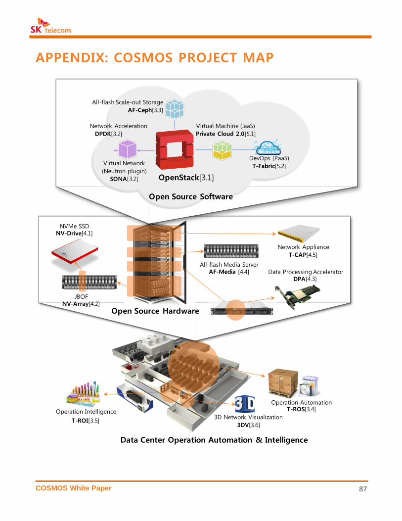
COSMOS White Paper 87
APPENDIX: COSMOS PROJECT MAP
3D Network Visualization
3DV[3.6]
Operation Intelligence
T-ROI[3.5]
Operation AutomationT-ROS[3.4]
JBOFNV-Array[4.2]
NVMe SSDNV-Drive[4.1]
All-flash Media ServerAF-Media [4.4] Data Processing Accelerator
DPA[4.3]
Network Appliance
T-CAP[4.5]
Virtual Network
(Neutron plugin)
SONA[3.2]
All-flash Scale-out Storage
AF-Ceph[3.3]
OpenStack[3.1]
Network Acceleration
DPDK[3.2]
Virtual Machine (IaaS)
Private Cloud 2.0[5.1]
DevOps (PaaS)
T-Fabric[5.2]
Open Source Hardware
Open Source Software
Data Center Operation Automation & Intelligence

COSMOS White Paper 88
ABBREVIVATIONS
API: Application Programming Interface
BI: Business Intelligence
COSMOS: Composable, Open, Scalable,
Mobile-Oriented System
COTS: Commercial Off-The-Shelf
DAS: Direct-Attached Storage
DPA: Data Processing Accelerator
DPDK: Data Plane Development Kit
FPGA: Field Programmable Gate Array
FTL: Flash Translation Layer
IaaS: Infrastructure-as-a-Service
JBOF: Just a Bunch of Flash
IOPS: Input/output Operations Per Second
NAS: Network-Attached Storage
NFV: Network Function Virtualization
NVMe: Non-Volatile Memory express
OCP: Open Compute Project
OI: Operation Intelligence
ONF: Open Networking Foundation
ONOS: Open Network Operating System
OS: Operating System
OVS: Open Virtual Switch
PaaS: Platform-as-a-Service
PoC: Proof-of-Concept
RAN: Radio Access Network
SaaS: Software-as-a-Service
SAN: Storage Area Network
SDC: Software-Defined Compute
SDDC: Software-Defined Data Center
SDN: Software-Defined Networking
SDS: Software-Defined Storage
SR-IOV: Single Root-Input Output Virtualiza-
tion
SSD: Solid State Disk
TCO: Total Cost of Ownership
ToR: Top of Rack
VM: Virtual Machine
VMM: Virtual Machine Monitor
VNF: Virtualized Network Function

COSMOS White Paper 89
REFERENCES
[1] Cisco, Visual Networking Index: Global Mobile Data Traffic Forecast Update, 2015–2020
[2] Cisco, Global Cloud Index: Forecast and Methodology, 2014–2019
[3] NRDC, Data Center Efficiency Assessment 2014
[4] http://www.datacenterknowledge.com/the-facebook-data-center-faq-page-three/
[5] https://www.facebook.com/PrinevilleDataCenter/app/399244020173259
[6] http://www.hani.co.kr/arti/economy/it/733581.html
[7] http://www.theregister.co.uk/2016/01/07/gartner_enterprise_ssd_hdd_revenue_crossover_in_2017/
[8] http://www.forbes.com/sites/tomcoughlin/2016/01/15/digital-storage-projections-for-2016-part-
2/#6cff8e8b4e5c
[9] https://code.facebook.com/posts/203733993317833/opening-designs-for-6-pack-and-wedge-100/
[10] VMware, The VMware NSX Network Virtualization Platform
[11] VMware, Reducing Server Total Cost of Ownership with VMware Virtualization Software
[12] http://www.datacenterknowledge.com/archives/2013/11/20/facebook-ops-staffer-manages-20000-servers/
[13] OpenFlow Switch Specification Version 1.0, Dec. 31, 2009
[14] OpenStack User Survey 2015 https://www.openstack.org/assets/survey/Public-User-Survey-Report.pdf
[15] http://www.slideshare.net/Red_Hat_Storage/ceph-at-work-in-bloomberg-object-store-rbd-and-openstack
[16] https://yahooeng.tumblr.com/post/116391291701/yahoo-cloud-object-store-object-storage-at
[17] NFV Standards rev 2(ETSI GW NFV 002 V1.1.1), 2013
[18] SK telecom, ATSCALE White Paper, 2016
[19] IHS Infonetics Data Center Network Equipment 2015
[20] https://wiki.onosproject.org/display/ONOS/DC+Network+Virtualization
[21] http://www.yang-central.org
[22] https://tools.ietf.org/html/rfc6020
[23] https://tools.ietf.org/html/rfc4271
[24] Luc Ghein, “MPLS fundamentals”, Nov. 21, 2006 (ISBN-1-58705-197-4)
[25] Butler W. Lampson and Howard E. Sturgis, “Reflections on an Operating System Design”, in Communica-
tions of the ACM 19(5), pp. 251 – 265, May, 1976
[26] http://www.slideshare.net/openstack_kr/openstack-days-korea-2016-track1-all-flash-ceph/7
[27] The Comparison of Ceph and Commercial Server SAN https://www.openstack.org/assets/Uploads/The-
Comparison-of-Ceph-and-Commercial-Server-SAN.pdf
[28] http://calamari.readthedocs.org/en/latest/
[29] https://01.org/virtual-storage-manager
[30] https://www.intel.com/content/www/us/en/servers/ipmi/ipmi-home.html
[31] P. Russom, “Operational Intelligence: Real-Time Business Analytics for Big Data”, August, 2012
[32] C White, “The Next Generation of Business Intelligence: Operational BI”, DM Review Magazine, May 2005,
http://www.information-management.com/issues/20050501/1026064-1.html
[33] “Operational Intelligence: What It Is and Why You Need It Now”, CITO Research, April 2013
[34] http://www.anandtech.com/show/10098/market-views-2015-hard-drive-shipments

COSMOS White Paper 90
[35] Bose R. C., Ray Chaudhuri, D.K., “On A Class of Error Correcting Binary Group Codes”, in Information and
Control, pp. 68 – 79, ISSN 0890-5401
[36] Lawton George, “Developing Software Online with Platform-as-a-Service Technology”, in Computer, Vol.
41, Issue 6, pp. 13 ~ 15, 2008
[37] Keller Eric and Jennifer Rexford, “The “Platform as a Service” Model for Networking”, INM/WREN, 2008
[38] IDC report, “PaaS Global Market”, 2013
[39] Gartner report, “Market Trends: Platform as a Service, Worldwide, 2012 – 2016”, 2012
[40] Roche James, “Adopting DevOps practices in Quality Assurance” in Communications of the ACM 56. 11,
pp. 38 - 43, 2013
[41] T developers: http://developers.sktelecom.com/resource/api
[42] https://github.com/google/cadvisor
[43] https://github.com/naver/pinpoint
[44] Intel ONP Server Release 2.0 Performance Test Report, Revision 1.0, September, 2015