small animal whole body imaging with metamaterial inspired ... · small animal whole-body imaging...
TRANSCRIPT

Small animal whole-body imaging with metamaterial-inspired RF coil
Mikhail Zubkov1, Anna A. Hurshkainen
1, Ekaterina A. Brui
1, Stanislav B. Glybovski
1, Mikhail
V. Gulyaev2, Nikolai V. Anisimov
2, Dmitry V. Volkov
3, Yury A. Pirogov
4, Irina V.
Melchakova1
1Department of Nanophotonics and Metamaterials, ITMO University, Saint-Petersburg, Russia
2 Laboratory of Magnetic Resonance and Spectroscopy, Faculty of Fundamental Medicine,
Lomonosov Moscow State University, Moscow, Russia
3Department of Physics of Accelerators and Radiation Medicine, Faculty of Physics, Lomonosov
Moscow State University, Moscow, Russia
4Department of Photonics and Microwave Physics, Faculty of Physics, Lomonosov Moscow
State University, Moscow, Russia
List of abbreviations:
RF – radiofrequency
FoV – field of view
SNR – signal to noise ratio
CNR – contrast to noise ratio

Abstract
Preclinical magnetic resonance imaging often requires the entire body of an animal to be imaged
with sufficient quality. This is usually performed by combining regions scanned with small coils
with high sensitivity or long scans using large coils with low sensitivity. Here, a metamaterial-
inspired design employing a parallel array of wires operating on the principle of eigenmode
hybridization is used to produce a small animal whole-body imaging coil. The coil field
distribution responsible for the coil field of view and sensitivity is simulated in an
electromagnetic simulation package and the coil geometrical parameters are optimized for the
chosen application. A prototype coil is then manufactured and assembled using brass telescopic
tubes and copper plates as distributed capacitance, its field distribution is measured
experimentally using B1+ mapping technique and found to be in close correspondence with
simulated results. The coil field distribution is found to be suitable for whole-body small animal
imaging and coil image quality is compared with a number of commercially available coils by
whole-body living mice scanning. Signal to noise measurements in living mice show outstanding
coil performance compared to commercially available coils with large receptive fields, and
rivaling performance compared to small receptive field and high-sensitivity coils. The coil is
deemed suitable for whole-body small animal preclinical applications.
Introduction
Small animal imaging is crucial to a majority of preclinical research. A number of applications in
preclinical magnetic resonance imaging (MRI) requires full body images of small animals (e.g.,
mice) to be acquired, for example angiography1, fat quantification
2, contrast agent or drug
delivery3–5
and more6. Conventionally, such images are obtained either through stitching of
multiple fields of view (FoV) sequentially acquired with small surface coil or with a single
volume coil (usually, a birdcage coil). Both approaches have their own benefits and drawbacks.
Birdcage coils provide uniform excitation (B1+) and reception (B1
-) within their internal volume
7.
The areas of field homogeneity provided by such coils are enough for small animal whole-body
imaging even at high frequencies where the wavelength of the used radiofrequency (RF) field
shortens leading to uniformity issues in human MRI8. The downside of using volume coils is in
the low sensitivity they provide and the large area they collect the noise from. These two
combined effects lead to generally low signal-to-noise ratio (SNR) in images obtained with
birdcage coils. Another drawback of a birdcage is its closed geometry completely surrounding
the studied subject except for the front and the back coil ends. In applications where an external
excitation or monitoring is required (e.g. acoustic excitation9), this coil design provides limited
access and is, therefore, inconvenient.
The other option for full-body imaging, i.e. using small surface coils and combining the results
during post-processing, provides high SNR due to better sensitivity of small surface coils at
depths comparable to coil size. The small volume coverage of surface coil is corrected for during
post-processing by stitching a number of fields of view together. As often image stitching is
performed manually or semi-automatically10,11
imaging in vivo introduces a risk inconsistencies
between the registered volumes due to physiological movement. Another aspect of small surface
coils that is usually not corrected during post-processing is the non-uniformity of B1+ and B1
-
leading to uneven signal (and consequently SNR and CNR) distribution in the acquired images,
although robust algorithms for image fusion might provide seamless results even when the
original images have non-uniform sensitivity12
.
There is a gap in technological solutions for this sensitivity versus coverage tradeoff, which this
work is aimed to close. An intermediately sized coil with B1+ and B1
- uniformity better than one
of conventional surface coils and rivaling sensitivity should provide whole-body small animal
imaging without the need of post-acquisition fusion as well as SNR high enough to allow
preclinical MRI experiments to be carried out.
Experimental
Coil design
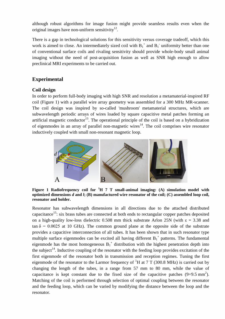
In order to perform full-body imaging with high SNR and resolution a metamaterial-inspired RF
coil (Figure 1) with a parallel wire array geometry was assembled for a 300 MHz MR-scanner.
The coil design was inspired by so-called 'mushroom' metamaterial structures, which are
subwavelength periodic arrays of wires loaded by square capacitive metal patches forming an
artificial magnetic conductor13
. The operational principle of the coil is based on a hybridization
of eigenmodes in an array of parallel non-magnetic wires14
. The coil comprises wire resonator
inductively coupled with small non-resonant magnetic loop.
Figure 1 Radiofrequency coil for 1H 7 T small-animal imaging: (A) simulation model with
optimized dimensions d and l; (B) manufactured wire resonator of the coil; (C) assembled loop coil,
resonator and holder.
Resonator has subwavelength dimensions in all directions due to the attached distributed
capacitance15
: six brass tubes are connected at both ends to rectangular copper patches deposited
on a high-quality low-loss dielectric 0.508 mm thick substrate Arlon 25N (with ε = 3.38 and
tan δ = 0.0025 at 10 GHz). The common ground plane at the opposite side of the substrate
provides a capacitive interconnection of all tubes. It has been shown that in such resonator type
multiple surface eigenmodes can be excited all having different B1+ patterns. The fundamental
eigenmode has the most homogeneous B1+ distribution with the highest penetration depth into
the subject14
. Inductive coupling of the resonator with the feeding loop provides excitation of the
first eigenmode of the resonator both in transmission and reception regimes. Tuning the first
eigenmode of the resonator to the Larmor frequency of 1H at 7 T (300.8 MHz) is carried out by
changing the length of the tubes, in a range from 57 mm to 80 mm, while the value of
capacitance is kept constant due to the fixed size of the capacitive patches (9×9.5 mm2).
Matching of the coil is performed through selection of optimal coupling between the resonator
and the feeding loop, which can be varied by modifying the distance between the loop and the
resonator.
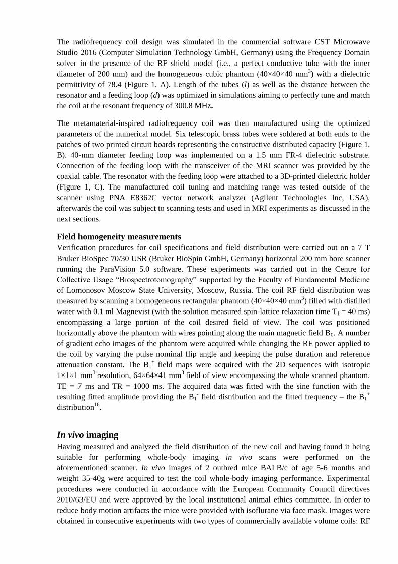
The radiofrequency coil design was simulated in the commercial software CST Microwave
Studio 2016 (Computer Simulation Technology GmbH, Germany) using the Frequency Domain
solver in the presence of the RF shield model (i.e., a perfect conductive tube with the inner
diameter of 200 mm) and the homogeneous cubic phantom (40×40×40 mm3) with a dielectric
permittivity of 78.4 (Figure 1, A). Length of the tubes (l) as well as the distance between the
resonator and a feeding loop (d) was optimized in simulations aiming to perfectly tune and match
the coil at the resonant frequency of 300.8 MHz.
The metamaterial-inspired radiofrequency coil was then manufactured using the optimized
parameters of the numerical model. Six telescopic brass tubes were soldered at both ends to the
patches of two printed circuit boards representing the constructive distributed capacity (Figure 1,
B). 40-mm diameter feeding loop was implemented on a 1.5 mm FR-4 dielectric substrate.
Connection of the feeding loop with the transceiver of the MRI scanner was provided by the
coaxial cable. The resonator with the feeding loop were attached to a 3D-printed dielectric holder
(Figure 1, C). The manufactured coil tuning and matching range was tested outside of the
scanner using PNA E8362C vector network analyzer (Agilent Technologies Inc, USA),
afterwards the coil was subject to scanning tests and used in MRI experiments as discussed in the
next sections.
Field homogeneity measurements
Verification procedures for coil specifications and field distribution were carried out on a 7 T
Bruker BioSpec 70/30 USR (Bruker BioSpin GmbH, Germany) horizontal 200 mm bore scanner
running the ParaVision 5.0 software. These experiments was carried out in the Centre for
Collective Usage “Biospectrotomography” supported by the Faculty of Fundamental Medicine
of Lomonosov Moscow State University, Moscow, Russia. The coil RF field distribution was
measured by scanning a homogeneous rectangular phantom (40×40×40 mm3) filled with distilled
water with 0.1 ml Magnevist (with the solution measured spin-lattice relaxation time T1 = 40 ms)
encompassing a large portion of the coil desired field of view. The coil was positioned
horizontally above the phantom with wires pointing along the main magnetic field B0. A number
of gradient echo images of the phantom were acquired while changing the RF power applied to
the coil by varying the pulse nominal flip angle and keeping the pulse duration and reference
attenuation constant. The B1+ field maps were acquired with the 2D sequences with isotropic
1×1×1 mm3
resolution, 64×64×41 mm3
field of view encompassing the whole scanned phantom,
TE = 7 ms and TR = 1000 ms. The acquired data was fitted with the sine function with the
resulting fitted amplitude providing the B1- field distribution and the fitted frequency – the B1
+
distribution16
.
In vivo imaging
Having measured and analyzed the field distribution of the new coil and having found it being
suitable for performing whole-body imaging in vivo scans were performed on the
aforementioned scanner. In vivo images of 2 outbred mice BALB/c of age 5-6 months and
weight 35-40g were acquired to test the coil whole-body imaging performance. Experimental
procedures were conducted in accordance with the European Community Council directives
2010/63/EU and were approved by the local institutional animal ethics committee. In order to
reduce body motion artifacts the mice were provided with isoflurane via face mask. Images were
obtained in consecutive experiments with two types of commercially available volume coils: RF

RES 300 1H/13C T10334 (inner diameter of 72 mm) and RF RES 1H T6594 (inner diameter of
115 mm). Additionally a small FoV image of mouse kidneys was acquired with a rat-brain
receive-only surface coil (T11205 with length, width and height of 123 mm, 64 mm, 31 mm
respectively with a resonator length of 17 mm) with excitation provided by the smaller birdcage
coil (i.e., the cross-coil operating mode). In order to provide comparable imaging conditions care
was taken to ensure proper tuning of the coils, automatic procedures for transmitter power
calibration were checked to provide proper power attenuation values, receiver gain was kept
constant and B0 shimming was automatically optimized for each coil and mouse position.
Full body imaging was performed with a 2D SE pulse sequence using the following parameters:
FoV = 40×100 mm2, matrix = 200×200, slice thickness = 1.5 mm, flip angle= 90°, refocusing
flip angle = 180°, TR = 800 ms and TE = 14 ms. Small FoV kidney imaging was performed with
a similar pulse sequence with the parameters: FoV = 40×30 mm2, matrix = 266×200, slice
thickness = 1 mm, flip angle= 90°, refocusing flip angle = 180°, TR = 800 ms and TE = 13.64
ms with the exception of cross-coil imaging, where TE = 14.34 ms was used due to hardware
constrains.
Results
Coil design and simulations
The coil length (l) and distance to the loop coil (d) was optimized to achieve the best tuning at
the spectrometer frequency, resulting in the optimum parameters l = 65 mm d = 24 mm. The
frequency dependence of the reflection coefficient of the simulated coil with optimized
parameters and a similar measured dependence are depicted in Figure 2, showing proper tuning
and matching of the coil with the reflection coefficient lower than -19 dB at the scanner
operating frequency.
Figure 2 Simulated (-) and measured (--) frequency dependencies of the reflection coefficient of the
radiofrequency coil with optimal wire length l and wire separation a. The difference in the
measured and simulated Q-factor (resulting in the change in the resonance line width) is due to the
absence of the RF shield in on-bench measurements.
The B1+ field distribution created by the coil was simulated on the optimized model to assess the
field homogeneity, to find areas for possible small animal placement and to be later compared to
the experimentally obtained field profiles. Calculated field distributions in the vicinity of the coil
and inside the phantom volume at the top of the phantom (coronal plane) and in the central cross-

section (sagittal and axial planes) were extracted from a larger simulated volume (Figure 3, D, E
and F, for coronal, sagittal and axial planes correspondingly).
Figure 3 B1+
metrics of the metamaterial-inspired coil. (A) – simulated (–) and experimental (∙) field
profile in the center of the 40×40×40 mm3 homogeneous phantom normally to the coil wire plane.
(B) – field profiles in the direction of the wires 1 mm inside the phantom, (C) – field profiles in the
direction across the wires. (D) – simulated map of the normalized RF field in the coronal plane 1
mm inside the phantom (the white box shows the phantom border), (E) – in the sagittal plane in the
center of the phantom, (F) – in the axial plane. (G-I) – B1+
field distribution maps as measured on a
rectangular 40×40×40 mm3 homogeneous phantom. (G) – coronal plane 1 mm inside the phantom,
(H) and (I) – sagittal and axial planes in the in the center of the phantom.
In order to facilitate the comparison between the experimentally measured field and simulation
prediction field profiles inside the phantom, i.e. the dependencies of the B1
+ on the depth, length
and width of the phantom, were extracted from the simulation. The profiles correspond to the
field distributions along the central axis of the phantom for depth and to the top surface of the
phantom for length and width (Figure 3, A, B and C correspondingly). The field profile variation
(standard deviation over mean) inside the phantom along the wires was found to be on the order
of 1%, the variation across the wires was substantially higher, 33%.

Field homogeneity measurements
In order to compare the simulation results to the experimentally obtained coil field distribution
maps, the latter were normalized to the maximum field measured in the phantom volume (Figure
3). As expected, the coil was performing better closer to the coil surface with the transmission
and reception efficiency diminishing with distance from the wire plane. The field drop off with
distance, being the property limiting the use of surface coil for whole-body imaging was of
particular interest. The comparison between the simulated field of the coil and the
experimentally acquired B1+ distribution (Figure 3, A) shows fine correspondence in field drop
off. A significant sensitivity was found to be retained at the planned mouse positioning distance
(at least 40% of the sensitivity of the coil remained 20 mm inside the phantom in the planned
ventral-dorsal direction).
Both simulations (Figure 3, D-F) and experimental maps (Figure 3, G-I) show the presence of a
homogeneous field region suitable for positioning a small animal along the wire direction up to
20 mm away from the wire plane. Field variation profiles along selected directions were
extracted from the field map and compared to similar simulation results. The experimental
profiles show B1+ field distribution similar to one predicted in simulations (Figure 3, A-C). As
predicted by simulations, field profile along the wires (Figure 3, B) shows better uniformity in
the proposed cranial-caudal direction than in left to right direction (Figure 3, C): 3% variation
across the 40 mm of the phantom in cranial-caudal direction versus 13% variation across the 40
mm of the phantom in left-right direction (across the wires).
In vivo imaging
Field measurements and simulations have shown that whole-body mouse imaging with the
proposed coil will be possible for proper mouse positioning. During the in vivo imaging
experiments mouse torso was properly visualized in the chosen position. According to the
simulations and field measurements the image quality was expected to diminish over the distance
from the wire plane. The slice images on different distances from the coil (Figure 4) show
sufficient image quality with the SNR of the images obtained with the resonator coil only
slightly higher than one provided by the smaller birdcage coil on the slices closest (dorsal
coronal slices) and furthest (ventral coronal slices) from the wire plane and surpassing it by
around 300% in the area of optimal coil transmission and reception (Table 1).
Comparing small FoV images provided by birdcage coil (Figure 5, B and C), surface coil (Figure
6, B) and new resonator coil (Figure 5, A and Figure 6, A) shows renal pelvis and calyces as well
as larger renal vessels being equally well visualized on both new coil and surface coil images,
with the majority of the structures being obscured by noise in the both of the birdcage coil image
series. Comparison of SNR in small FoV imaging (Table 2) shows an over 200% increase in
SNR with the resonator coil compared to both birdcage coils and rivaling SNR with the surface
coil (with the full-body resonator coil showing only 25% less SNR compared to the surface coil).

Figure 4 Whole-body mouse images at (A-C) spine level (closest to the resonator coil), (D - F)
kidney level (intermediate distance) and (G – I) liver level (furthest from the resonator coil). Images
A, D, G were acquired with the proposed resonator coil, images B, E, H – with the medium 72 mm
T10334 birdcage coil and images C, F, I- with the larger 115 mm T6594 birdcage coil. Images are
presented at the same window/level settings. Regions of interest for SNR calculation are shown by
green (muscle region for signal calculation) and red (signal-free region for noise calculation) circles.
A summary of SNR values at selected RF field penetration depths is presented in Table 1.

Figure 5 Mouse kidneys imaged with A – new resonator coil, B - 72 mm T10334 birdcage coil and C
– with the larger 115 mm T6594 birdcage coil. Images are presented at the same window/level
settings. Regions of interest for SNR calculation are shown by green (kidney parenchyma region for
signal calculation) and red (signal-free region for noise calculation) circles. A summary of SNR
values is presented in Table 2.
Figure 6 Second mouse kidney images obtained in a different scanning session (compared to Figure
4 and Figure 5 images). Image A was obtained with the proposed resonator coil, image B – with a
rat-brain receive-only surface coil T11205. Images are normalized to the signal value in muscle and
presented at the same window/level settings. Regions of interest for SNR calculation are shown by
green (kidney parenchyma region for signal calculation) and red (signal-free region for noise
calculation) circles. A summary of SNR values is presented in Table 2.
Table 1 SNR measurements summary for whole-body imaging at different distance from the
resonator coil surface compared to SNR measurements in images from birdcage coils acquired at
the same level. Areas for signal and noise measurements have been chosen as highlighted in Figure
4.
Resonator coil 72 mm birdcage 115 mm birdcage
Dorsal 52 25 23
Median 102 29 25
Ventral 67 37 28
Table 2 SNR measurements summary for kidney imaging with the proposed metamaterial-inspired
resonator coil compared to SNR measurements in images acquired with birdcage coils and surface
coil. The positioning of regions of interest for signal and noise calculation is shown in Figure 5 and
Figure 6.
Mouse 1 Mouse 2
Resonator coil 17.4 12.8
Birdcage coil, 72 mm 5.8 -
Birdcage coil, 115 mm 6.3 -
Surface coil - 17.0

Discussion
The tested metamaterial inspired resonator coil design simulations have shown a field
distribution with high potential for whole body mouse imaging with high SNR and large field of
view. The measured RF field distribution of the real RF coil showed fine correspondence with
the simulated results. The RF field distribution along the coil wires (corresponding to the
proposed cranial-caudal direction of mouse positioning in the coil) showed high homogeneity in
phantom imaging (3% variation of the RF field magnitude across the 40 mm of the phantom).
The field distribution across the wires was less homogeneous (13% field variation across 40 mm
of the phantom in the proposed left to right direction of mouse imaging). The field distribution in
left to right direction on the other hand has a visible maximum in the center of the imaging field
well suited for placing a small animal in the optimum reception and transmission field area. The
coil field rapidly decreases normally to the wire plane, where the dimensions of the imaged
animal should be the smallest (i.e., ventral-dorsal direction). On the 20 mm of common mouse
thickness in ventral-dorsal direction the coil field drop-off was below 60% resulting in SNR still
higher than the volume birdcage coils can provide. The inhomogeneous field distribution
normally to the coil resulted in inhomogeneous flip angle distribution in the said direction, which
in turn (when classical pulse calibration via finding an echo minimum in an axial slice17
was
used) resulted in optimum flip angle being only tuned in a limited spatial region. This can be
seen in the in vivo SNR measurements (Table 1), where greater field in dorsal regions of the
mouse (meaning greater sensitivity) provides less SNR due to flip angle being larger than
optimal angle for the selected pulse sequence. Similar SNR variation was observed in small FoV
imaging. Maximum SNR was nevertheless provided by the coil in the visceral region of the
imaged animal, which is usually of greater interest than the peripheral regions of the animal.
Moreover such field and sensitivity distribution allows obtaining maximum SNR at desired field
penetration depth by tuning the RF power to the coil if different portions of the object present
significant interest.
The SNR measurements in vivo show the metamaterial inspired coil sensitivity surpassing one of
volume birdcage coils by at least 200% in the maximum sensitivity region and by at least 80%
off the region of the highest coil sensitivity. The coil thus shows exceptional performance in its
designated task (i.e., whole-body mouse imaging). Additionally comparing it to a number of
coils in small FoV application has shown it to provide sensitivity high enough to visualize
structures attainable only through the use of small receive-only surface coils. This allows the coil
to be used in multiresolution applications, where both a large field of view and a detailed image
of particular region are desirable (e.g., drug delivery monitoring). One of the downsides of the
coil in current implementation is a limited field of view in cranial-caudal direction, resulting in
the mouse head and the most caudal regions being impossible to image simultaneously.
Nevertheless it was possible to image the head and partially the body of the mouse
simultaneously by moving the coil cranially. In that case, the body was imaged approximately
down to the mouse urinary bladder level with the more caudal structures being outside the coil
FoV. In case full body coverage is required the coil design should be modified by reducing the
structural capacity and extending the wire length, providing therefore a longer FoV at the same
resonant frequency. Further improvements can include an active detuning circuit to operate the
coil in receive-only mode with excitation by volume coil (if delivering sufficient pulse power to
the coil is possible) thus providing uniform flip angle across the imaging volume and high
receive sensitivity in whole-body applications.

The tested metamaterial-inspired coil has therefore been shown to be suitable for whole-body
mouse imaging with high SNR, capable of providing large and small FoV images without mouse
or coil repositioning and having potential for further improvements if a need for better transmit
homogeneity or larger FoV arises. At the same time the tested coil geometry is open allowing
easier access to the animal for suitable applications.
Acknowledgements
This work was financially supported by the Ministry of Education and Science of the Russian
Federation (Zadanie No. 3.2465.2017/4.6). This project has also received funding from the
European Union's Horizon 2020 research and innovation programme under grant agreement No
736937. Additionally, the authors would like to thank Dr. Redha Abdeddaim for useful
discussions.
References
1. Lefrançois W, Thiaudière E, Ben Hassen W, Sanchez S, Franconi J-M, Miraux S. Fast
whole-body magnetic resonance angiography in mice. Magn Reson Med. 2011;66(1):32-39.
doi:10.1002/mrm.22985.
2. Schmidt MV, Schmidt MV, Czisch M, et al. Chronic social stress during adolescence in
mice alters fat distribution in late life: Prevention by antidepressant treatment. Stress.
2009;12(1):89-94. doi:10.1080/10253890802049343.
3. Odintsov B, Chun JL, Berry SE. Whole body MRI and fluorescent microscopy for
detection of stem cells labeled with superparamagnetic iron oxide (SPIO) nanoparticles and
DiI following intramuscular and systemic delivery. In: Turksen K, ed. Imaging and
Tracking Stem Cells. Vol 1052. Totowa, NJ: Humana Press; 2013:177-193.
doi:10.1007/7651_2013_13.
4. Markides H, Kehoe O, Morris RH, El Haj AJ. Whole body tracking of superparamagnetic
iron oxide nanoparticle-labelled cells – a rheumatoid arthritis mouse model. Stem Cell Res
Ther. 2013;4(5):126. doi:10.1186/scrt337.
5. Odintsov B, Chun JL, Mulligan JA, Berry SE. 14.1 T whole body MRI for detection of
mesoangioblast stem cells in a murine model of duchenne muscular dystrophy. Magn Reson
Med. 2011;66(6):1704-1714. doi:10.1002/mrm.22942.
6. Khmelinskii A, Plenge E, Kok P, et al. Super-resolution reconstruction of whole-body MRI
mouse data: An interactive approach. In: IEEE; 2012:1723-1726.
doi:10.1109/ISBI.2012.6235912.
7. Kathiravan S, Kanakaraj J. A review on potential issues and challenges in MR imaging. Sci
World J. 2013;2013:1-10. doi:10.1155/2013/783715.
8. Collins CM, Wang Z. Calculation of radiofrequency electromagnetic fields and their effects
in MRI of human subjects: RF Field Calculations in MRI. Magn Reson Med.
2011;65(5):1470-1482. doi:10.1002/mrm.22845.
9. Liu Y, Royston TJ, Klatt D, Lewandowski ED. Cardiac MR elastography of the mouse:
Initial results. Magn Reson Med. 2016;76(6):1879-1886. doi:10.1002/mrm.26030.

10. Vossen M, Teeuwisse W, Reijnierse M, Collins CM, Smith NB, Webb AG. A
radiofrequency coil configuration for imaging the human vertebral column at 7 T. J Magn
Reson. 2011;208(2):291-297. doi:10.1016/j.jmr.2010.11.004.
11. Webb AG, Collins CM, Versluis MJ, Kan HE, Smith NB. MRI and localized proton
spectroscopy in human leg muscle at 7 Tesla using longitudinal traveling waves. Magn
Reson Med. 2010;63(2):297-302. doi:10.1002/mrm.22262.
12. Dzyubachyk O, Lelieveldt BPF, Blaas J, Reijnierse M, Webb A, van der Geest RJ.
Automated algorithm for reconstruction of the complete spine from multistation 7T MR
data. Magn Reson Med. 2013;69(6):1777-1786. doi:10.1002/mrm.24404.
13. Sievenpiper D, Zhang L, Broas RFJ, Alexopolous NG, Yablonovitch E. High-impedance
electromagnetic surfaces with a forbidden frequency band. IEEE Trans Microw Theory
Tech. 1999;47(11):2059-2074. doi:10.1109/22.798001.
14. Hurshkainen A, Nikulin A, Georget E, et al. A novel metamaterial-inspired RF-coil for
preclinical dual-nuclei MRI. ArXiv170904761 Phys. September 2017.
http://arxiv.org/abs/1709.04761. Accessed October 12, 2017.
15. Glybovski SB, Shchelokova AV, Kozachenko AV, et al. Capacitively-loaded metasurfaces
and their application in magnetic resonance imaging. In: Belle Mare, Mauritius: IEEE;
2015:1-2. doi:10.1109/RADIO.2015.7323400.
16. Barker GJ, Simmons A, Arridge SR, Tofts PS. A simple method for investigating the
effects of non-uniformity of radiofrequency transmission and radiofrequency reception in
MRI. Br J Radiol. 1998;71(841):59-67. doi:10.1259/bjr.71.841.9534700.
17. Carlson JW, Kramer DM. Rapid radiofrequency calibration in MRI. Magn Reson Med.
1990;15(3):438-445. doi:10.1002/mrm.1910150309.