specifications for gas insulated metal clad 69kv switchgear · 4.1.1 the gas insulated switchgear...
TRANSCRIPT
Saudi Electricity Company الشركة السعودية للكھرباء
SEC Distribution Materials Specifications 32-SDMS-10 Rev 0
DATE: 30-06-2013G
32-SDMS-10
Rev 0
SPECIFICATIONS
FOR
GAS INSULATED METAL CLAD 69KV SWITCHGEAR
This specification is property of SEC and
subject to change or modification without any prior notice
Saudi Electricity Company الشركة السعودية للكھرباء
SEC Distribution Materials Specifications 32-SDMS-10 Rev 0
DATE: 30-06-2013G
Page 2 of 65
TABLE OF CONTENTS
1.0 SCOPE
2.0 CROSS REFERENCES
3.0 APPLICABLE CODES AND STANDARDS
4.0 DESIGN AND CONSTRUCTION REQUIREMENTS
4.1 General 4.2 Ratings 4.3 Layout 4.4 Internal Fault and Pressure Limiting Devices 4.5 SF6 Gas System Requirements 4.6 Wiring and Terminal Blocks 4.7 Grounding 4.8 Nameplate 4.9 Bus bar Assemblies 4.10 Circuit Breakers 4.11 Disconnect and Grounding Switches 4.12 Current Transformers (CTs) 4.13 Potential Transformers (PTs) 4.14 Interlocking 4.15 Sealing End box for Underground Cable Termination 4.16 SF6-to-Air Overhead Line Termination 4.17 SF6-to-Oil Transformer Termination 4.18 Gas Insulated Surge Arresters 4.19 Local Control Cabinet 4.20 Substation Automation 4.21 On line Partial Discharge Monitoring 4.22 Drawings
5.0 BASIC REQUIREMENTS AND GUIDELINES
6.0 TESTS
7.0 SPECIAL TOOLS
8.0 DATA SCHEDULE

Saudi Electricity Company الشركة السعودية للكھرباء
SEC Distribution Materials Specifications 32-SDMS-10 Rev 0
DATE: 30-06-2013G
Page 3 of 65
1.0 SCOPE
This SEC Distribution Material Specification (SDMS) specifies the minimum technical requirements for design, engineering, manufacture, inspection, testing and performance of SF6, gas insulated metal-enclosed switchgears (GIS), to be installed indoors (with or without having outdoor terminations and associated exit bus ducts) in the 69kV, intended to be used in the Distribution system of the Saudi Electricity Company, Saudi Arabia.
2.0 CROSS REFERENCES
This Material Standard Specification shall always be read in conjunction with latest SEC General Specification No. 01-SDMS-01, titled "General Requirements for All Equipment/Materials", which shall be considered as an integral part of this SDMS. This SDMS shall also be read in conjunction with SEC Purchase Order or Contract Schedules for project, as applicable.
3.0 APPLICABLE CODES AND STANDARDS
The latest revision/amendments of the following Codes and Standards shall be applicable for the equipment/material covered in this SDMS. In case of conflict, the vendor/manufacturer may propose equipment/material conforming to one group of Industry Codes and Standards quoted hereunder without jeopardizing the requirements of this SDMS.
3.1 IEC 61892 -1 Instrument Transformers, Part 1 General requirements
3.2 IEC 61869-2 Instrument Transformers, Part 2: Additional Requirements
for Current Transformers 3.3 IEC 61869-3 Instrument Transformers, Part 3: Additional requirements for
Inductive Voltage Transformers
3.4 IEC 60044-6 Instrument transformers Part 6: Requirements for Protective Current Transformers for Transient Performance
3.5 IEC 60099-4 Surge arresters- Part 4: Metal-oxide surge arresters without
gaps for a.c. Systems
Saudi Electricity Company الشركة السعودية للكھرباء
SEC Distribution Materials Specifications 32-SDMS-10 Rev 0
DATE: 30-06-2013G
Page 4 of 65
3.6 IEC 60099-5 Surge Arresters-Part 5: Selection and application recommendations
3.7 IEC 60255 Electrical Relays (Applicable Parts)
3.8 IEC 60376 Specification of technical grade sulfur hexafluoride (SF6) for
use in electrical equipment
3.9 IEC 60445 Basic and safety principles for man-machine interface, marking and identification-Identification of equipment terminals and conductor terminationsand conductors.
3.10 IEC 60502-1 Power cables with extruded insulation and their accessories for rated voltages from 1 kV (Um =1.2 kV) up to 30 kV (Um = 36 kV) Part 1: Cables for rated voltages of 1 kV (Um = 1.2 kV) and 3 kV (Um = 3.6)
3.11 IEC 60529 Degrees of Protection Provided by Enclosures (IP code)
3.12 IEC 61439 Low-voltage switchgear and controlgear assemblies-Part-2: Power Switchgear and Controlgear assemblies.
3.13 IEC 61850 Communication networks and systems in substations
3.14 IEC 62271-1 High-voltage switchgear and controlgear-Part 1: Common specifications
3.15 IEC 62271-100 High-voltage switchgear and controlgear Part-100:
Alternating current circuit-breakers
3.16 IEC 62271-101 High –voltage switchgear and controlgear-Synthetic testing
3.17 IEC 62271-102 High-voltage Switchgear and Controlgear Part-102: Alternating current disconnectors and earthing switches
3.18 IEC 62271-104 High-Voltage Switches and control gear Part-104:
Alternating current switches for rated voltage of 52kV and above
3.19 IEC 62271-110 High voltage Switchgear and Controlgear Part-110:
Inductive load switching

Saudi Electricity Company الشركة السعودية للكھرباء
SEC Distribution Materials Specifications 32-SDMS-10 Rev 0
DATE: 30-06-2013G
Page 5 of 65
3.20 IEC 62271-203 High-voltage switchgear and controlgear Part-203:Gas-
insulated metal-enclosed switchgear for rated voltages above 52 kV
3.21 IEC 62271-209 High voltage Switchgear and controlgear Part-209: Cable connections for gas-insulated metal-enclosed switchgear for rated voltage above 52 kV-Fluid filled and extruded insultion cables-Fluid filled and dry-type cable – terminations
3.22 IEEE C37.1 IEEE Standard Definition, Specification and analysis of
System Used for Supervisory Control, Data Acquisition and Automatic Control
3.23 IEEE C37.12 Guide for Specification of High Voltage Circuit Breakers
(over 1000 Volts)
3.24 IEEE C37.122 High Voltage Gas Insulated SubstationsRated Above 52 kV
3.25 IEEE C 37.06 AC High-Voltage Circuit Breaker Rated on a Symmetrical Current Basis-Preferred Ratings and Related Required Capabilities for voltages above 1000V
3.26 ANSI/IEEE C37.123 Guide to Specifications for Gas Insulated, Electric Power
substation Equipment
3.27 IEEE C57.13 IEEE Standard Requirements for Instrument Transformers
3.28 IEEE 1291 IEEE Guide for Partial Discharge Measurements in Power Switchgear
3.29 IEEE 1300 Guide for Cable Connections for Gas-Insulated Substations
3.30 NEMA CC 1 Electric Power Connectors for Substations
3.31 ASTM B-8 Standard Specification for Concentric-Lay Stranded Copper
Conductors, Hard, Medium Hard or soft

Saudi Electricity Company الشركة السعودية للكھرباء
SEC Distribution Materials Specifications 32-SDMS-10 Rev 0
DATE: 30-06-2013G
Page 6 of 65
4.0 DESIGN AND CONSTRUCTION REQUIREMENTS
4.1 General
4.1.1 The Gas Insulated Switchgear (GIS) shall be a complete unit comprised of
main equipment, all control and protection, monitoring, measuring and auxiliary devices and systems including interconnections, all termination joints at interfaces, mechanical linkages, couplings, SF6 gas piping, cabling, wiring, grounding materials etc. required for proper and satisfactory operation.
4.1.2 The GIS shall be:
a. of compact and modular design with individual equipment modules
connected together to form a complete assembly. Circuit-breaker, disconnect switch and grounding switch, cable termination, PT, exit bus duct and CT (with cores located within gas compartment) shall be in separate gas tight compartment. CT insulation shall be “Class F”.
b. of either single-phase enclosure type or three-phase enclosure type for
voltage levels of 230kV and below.
c. installed on suitable pads or supporting frames/structures with provision for leveling, including fasteners to foundation, which shall also be included in the supply. Support-structures shall be designed and fabricated to withstand the short circuit forces of the ground fault current.
d. having expansion joints and flexible connections, where several enclosures are connected in the longitudinal direction, such as main bus. Expansion joints provided for installation alignment shall be locked in place when alignment is complete. Expansion joints for compensation of thermal expansion and erection tolerances shall have the means to preserve mechanical integrity of the enclosure and the plug-in contacts for the conductor.
e. provided with galleries, stairways, movable platform or walkways for
accessing the equipment above two meters for maintenance and operation. All structures, movable platform, galleries, stairways and walkways shall have grounding provision and shall conform to the

Saudi Electricity Company الشركة السعودية للكھرباء
SEC Distribution Materials Specifications 32-SDMS-10 Rev 0
DATE: 30-06-2013G
Page 7 of 65
relevant Occupational Safety and Health Administration (OSHA) regulations.
f. All “ON” and “OFF” indications and SF6 gas pressure gauges shall be
installed in a visible location.
4.1.3 For GIS with single phase enclosures, each gas compartment of each phase shall be monitored independently.
4.1.4 The GIS enclosure shall be safe to touch and fully ensure operational security
and personnel safety under all normal and fault conditions with the maximum allowed induced voltage in the enclosure of 65 volts.
4.1.5 The switchgear and all its components and accessories shall be designed for
minimum maintenance during service. The manufacturer shall state the minimum interval between minor inspections (which will be restricted to visual checking and adjustments of external parts only) and major inspection/overhaul, including refilling or replenishment of gas and cleaning of the contaminant or filter in the circuit breaker chamber(s). Suitable openings shall be provided in the circuit breaker, disconnect and grounding switch modules for major inspection/adjustments. All motors shall be in accordance with IEC 60034. The bearings and other such parts shall be permanently lubricated for the entire service life. Padlocks shall be made of stainless steel or brass.
4.1.6 The GIS interface points shall be carefully coordinated with other equipment
such as overhead lines, cables, transformers, reactors, capacitor banks, etc., supplied by other manufacturers in order to ensure full compatibility. The design criteria for outdoor portion of the GIS bus duct leading to SF6-to-Air Overhead Line Termination / SF6-to-Oil Transformer Termination shall be as mentioned in clause 4.2.2 and in the data schedule.
4.1.7 All modules of the switchgear and components of the same rating and
construction, which may need to be replaced, shall be strictly interchangeable.
4.1.8 Degree of protection for all operating and driving mechanism shall be IP54 as per IEC 60529. The degree of protection for control cabinets, auxiliary equipment enclosures and all accessories shall be per 01-SDMS-01.
4.1.9 To facilitate transport and handling, lifting eyes or other suitable attachments
shall be provided with each GIS module.

Saudi Electricity Company الشركة السعودية للكھرباء
SEC Distribution Materials Specifications 32-SDMS-10 Rev 0
DATE: 30-06-2013G
Page 8 of 65
4.1.10 Each module of switchgear, consisting of individual elements intended to be
directly connected together, shall be constructed as a transportable assembly suitable for shipping and transportation without being dismantled.
4.1.11 All new gaskets, sealants and desiccants for permanent sealing of all field
joints and all access covers, removed during assembly, shall also be provided.
4.1.12 The GIS shall be designed per IEC 62271-203 or ANSI/IEEE C37.122
standard. The enclosure shall be capable of sustaining without damage all mechanical, electrical and thermal shocks that may occur in service during normal and fault conditions, including pressure effects of internal fault arc current of specified short circuit level and time. The enclosure assembly, material and design shall be such as to minimize induced electrical losses and heating effects which could occur in service under normal and fault conditions.
4.1.13 Joints and couplings between dissimilar metals shall be avoided to prevent
galvanic corrosion.
4.1.14 All supporting steel work shall be hot-dip galvanized per 01-SDMS-01.
4.1.15 A partition separating a compartment filled with insulating gas from a neighboring compartment such as a cable box, filled with liquid, shall not show any leakage affecting the dielectric properties of the two media.
4.1.16 The construction and thickness of the GIS enclosure and air storage tank of
the pneumatic operating mechanism shall conform to ANSI/ASME Boiler and Pressure Vessel Code, and ANSI/ASME B31.1 or equivalent.
4.1.17 All current carrying parts shall be made of electrolytic grade copper or
aluminum alloy.All interconnecting sections of current transferring parts shall be silver-plated.
4.1.18 All piping for SF6 gas, hydraulic and pneumatic operating mechanism
including their fittings shall be made of copper, brass or stainless steel.
4.1.19 All external connectors and terminal pads shall be made of copper or aluminum with tin-plating and designed per NEMA CC1. Terminal pads shall have 4 holes.

Saudi Electricity Company الشركة السعودية للكھرباء
SEC Distribution Materials Specifications 32-SDMS-10 Rev 0
DATE: 30-06-2013G
Page 9 of 65
4.1.20 Each circuit breaker, disconnect and grounding switch shall be provided with mechanically driven auxiliary switches. These auxiliary switches shall be provided with minimum six (6) normally open (NO) and six (6) normally closed (NC) spare auxiliary potential-free contacts preferably convertible at site in addition to those required for the operating mechanism control and indications, protection and interlocks with other equipment. The auxiliary contacts shall be of class-1, as per Table -6 of IEC 62271-1.
4.1.21 DC control/operating voltage shall be 125 Vdc, unless otherwise specified
and the operating voltage range shall be 90 Vdc to 140 Vdc.
4.2 Ratings
4.2.1 The specific ratings of the GIS equipment shall be as specified in the data schedule.
4.2.2 The switchgear shall be capable of carrying the specified rated current
continuously at the design ambient and specified ambient conditions in 01-SDMS-01, without temperature rise of various parts exceeding the limits stated in Table-3 of IEC 62271-1 or equivalent ANSI standards.
4.2.3 The maximum noise level produced by switchgear and its associated
apparatus during service shall not exceed the values specified in the data schedule.
4.2.4 All equipment and components of the switchgear including bus support
insulators shall conform to partial discharge level as per IEC 62271-203.
4.2.5 The insulation level requirements shall be as specified in 01-SDMS-01.
4.3 Layout
4.3.1 The layout shall be such that:
a. Future alterations and extensions can be undertaken in either direction by the same GIS manufacturer or GIS manufacturers other than the original manufacturer.
b. Maintenance or removal of a disconnect switch or circuit breaker shall not involve removal from service of adjacent disconnect switch or other equipment.

Saudi Electricity Company الشركة السعودية للكھرباء
SEC Distribution Materials Specifications 32-SDMS-10 Rev 0
DATE: 30-06-2013G
Page 10 of 65
c. Separate GIS bus link module with separate gas compartment shall be provided at both ends of the GIS for future extension of the GIS.
d. Adequate clearances around GIS shall be provided for free movement of SF6 gas service cart, CB maintenance and easy removal of largest GIS part.
e. Two maintenance grounding switches shall be provided across each
circuit breaker to measure the contact resistances of circuit breaker at site.
f. Sufficient clearances around bushing for cable HV AC testing shall be provided.
g. Adequate facilities shall be made available for neat storage of HV AC
cable-test bushing in the substation.
h. Adequate clearance shall be provided between GIS bays (inter-bay) for maintenace.
4.3.2 Care shall be taken for SF6 insulated duct connections between the power
transformers/shunt reactors, the outdoor wall-mounted bushings and the switchgear feeders with regard to an imaginable differential settlement of the concrete floors of switchgear-building and transformers/shunt reactors or supporting structures, respectively.
4.4 Internal Fault and Pressure Limiting Devices
4.4.1 The effect of an arc shall be confined to the compartment in which it has
been initiated and under no circumstances shall be allowed to spread out to adjacent compartments or other parts of the switchgear. The minimum burn-through time for the GIS enclosures shall be 300ms.
4.4.2 The over pressure created by internal arcing faults shall in no case be
allowed to exceed the withstand capability of the enclosure.
4.4.3 Rupture discs/pressure relief devices shall be fitted in each gas compartment including GIS surge arrester to relieve over pressure created by internal arcing faults automatically and instantaneously. Vent deflector shall be fitted with each rupture disc/pressure relief device to eliminate hazards to
Saudi Electricity Company الشركة السعودية للكھرباء
SEC Distribution Materials Specifications 32-SDMS-10 Rev 0
DATE: 30-06-2013G
Page 11 of 65
personnel and other equipment due to escaping gases or vapors under pressure.
4.5 SF6 Gas System Requirements
4.5.1 The SF6 gas shall conform to IEC 60376 or ASTM D2472.
4.5.2 The manufacturer shall provide the data regarding gas characteristics
corresponding to the degree of deterioration beyond which treatment or replacement of gas would become necessary along with procedural instructions for gas treatment to restore original quality.
4.5.3 The GIS shall be fully gas tight. All gas compartments shall contain suitable
agent to absorb moisture and any other decomposition products of SF6 gas.
4.5.4 SF6 gas relative leakage rate in each gas compartment pressure system shall not exceed 0.5% per year.
4.5.5 The GIS enclosure shall be sectionalized for each equipment into modular
units or compartments, separated by solid gas barriers with an effective sealing system. Each gas compartment shall be provided with evacuation/refilling port with self-closing non-return valves(s). Sampling, evacuation and refilling of SF6 shall be carried out without evacuation of any other section or loss of gas.
4.5.6 Gas barriers and sealing systems shall have adequate mechanical strength to
withstand the dynamic forces caused by short circuits, and effects of internal arc faults as well as maximum pressure differential that could exist between adjoining compartments, i.e. with full vacuum drawn on one side of the barrier and 1.5 times the operating pressure on the other side.
4.5.7 SF6 gas in each individual compartment shall be monitored by suitable
temperature-compensated pressure gauges and two-stage temperature compensated pressure (gas-density continuous monitoring) switches/relays to monitor the loss of SF6 gas. The dial of the pressure gauges shall be graduated to read pressures and colored green, yellow and red to indicate normal, Alarm Stage I (or non-urgent) and Alarm Stage II (or urgent) pressure conditions. The gas-density monitors shall be capable of being calibrated with the monitored equipment in service. Each pressure relay shall be provided with two convertible potential-free auxiliary contacts for

Saudi Electricity Company الشركة السعودية للكھرباء
SEC Distribution Materials Specifications 32-SDMS-10 Rev 0
DATE: 30-06-2013G
Page 12 of 65
two-stage alarm initiation as mentioned below. These alarm contacts shall be wired to the annunciator in the respective GIS bay control cabinet.
Stage I: Alarm at 10% above minimum safe operating gas density (and
block breaker closing) (Refill stage).
Stage II: Alarm in the event of gas density falling below the minimum safe operating limit (and block breaker tripping).
4.5.8 In the event of gas leakage, all parts of the switchgear in the affected
compartment shall be able to withstand continuously the rated voltage with SF6 gas at atmospheric pressure.
4.5.9 It shall be possible to test and replace each pressure gauge and the density
switch/relay without loss of gas.
4.5.10 The O-ring gasket shall be synthetic elastomeric type. The gasket shall resist oil and waste by-products of the SF6 gas decomposition. The gasket shall have minimum deformation in service life of GIS and also low gas and moisture permeability.
4.5.11 The SF6 gas pressure/density monitors shall be preferably directly coupled
to the gas compartment. The coupling with gas compartment shall be through self-closing non-return valve(s). Permanently fixed gas pipe work for SF6 gas pressure/density monitoring shall be installed (if required). The design, material, specification and associated fittings for all gas pipe work shall be rated for operation under normal and fault conditions and shall form part of the switchgear assembly during all testing carried at the manufacturer's works and at site. The gas piping system, valves etc. shall minimize the possibility of accidental third party damage and eliminate the need to dismantle the pipe work during maintenance and/or removal of modules, other than the pipe work associated with the maintenance item. The piping and SF6 gas pressure/density monitors shall be possible to replace without loss of SF6 gas.
4.5.12 At each gas compartment, provisions shall be made for connecting online
moisture measurement instrumentation and the gas service cart. The moisture content in the gas shall not exceed 150ppmv (parts per million per volume) in circuit breakers, and 250ppmv in other equipments. Provision for disconnection of gas pipelines shall be incorporated. 100µm or smaller
Saudi Electricity Company الشركة السعودية للكھرباء
SEC Distribution Materials Specifications 32-SDMS-10 Rev 0
DATE: 30-06-2013G
Page 13 of 65
sintered stainless steel particle filter disk, suitable for pressure involved, shall be installed at the gas service connection.
4.5.13 Filters shall be inserted in all gas compartments in addition to circuit
breaker compartment. The static filters provided inside the high-voltage enclosure shall not be shipped already fitted, but packed separately in air-tight sealed tin-cans and marked conspicuously. The gas decomposition product filter shall be effective for the duration of time between major overhauls. SF6 gas filters shall be as follows:
a. For moisture (H2O): Desiccant material such as Al2O3, also called
drying agent. The recommended particle size is 2-5mm.
b. For gaseous arc byproducts: Molecular sieve with a pore size of 4Å. Materials used for this purpose should not be regenerated.
c. For particles (generally dust residues) or solid arc byproducts: HEPA-
type or equivalent filter to remove particles with a size larger than 1µm.
4.5.14 A colored diagram with legends showing various gas compartments, piping, interconnections, valves, orifices and isolations to prevent current circulation, necessary controls and monitoring systems etc. together with normal and alarm ranges shall be mounted near each control cubicle for ease of monitoring.
4.5.15 The location of gas tight barrier insulators shall be clearly and permanently
marked with yellow or orange color and for gas through barriers with yellow with white strips or orange with white strips on the finished external surface of the GIS enclosures.
4.5.16 The switchgear assembly supplies shall include:
a. The initial complete filling of SF6 gas for the assembly and in addition,
any gas lost during installation and commissioning procedures.
b. An additional 10% supply of gas complete with containers and monitoring equipment for use during the warranty period.
4.5.17 Adequate arrangement for storage of SF6 gas adjacent to the installed
switchgear assembly shall be provided.

Saudi Electricity Company الشركة السعودية للكھرباء
SEC Distribution Materials Specifications 32-SDMS-10 Rev 0
DATE: 30-06-2013G
Page 14 of 65
4.5.18 Two gas density meters (for trip coil - 1 & 2) shall be provided for each circuit breaker compartments and trip signal for trip coils 1 & 2 shall be from independent gas density monitors if specified in the PTS/SOW.
4.6 Wiring and Terminal Blocks
4.6.1 All wiring between the switchgear assembly equipment and the control
cabinets shall be installed in raceways or galvanized rigid steel conduits or flexible steel tubing with PVC jacket and do not obstruct the maintenance access to devices/operating mechanism. The conduits shall be installed and located so as to minimize the accidental damage and to eliminate the need to dismantle the conduits during maintenance and/or removal of modules, other than the conduit associated with the maintenance item. The conduit shall be terminated via metallic adapters to ensure grounding.
4.6.2 All raceways cable fills shall be per NFPA 70. When a shielded control
cable enters a control cabinet, the cable shield shall be terminated immediately on the control cabinet enclosure. Cable with extruded copper shield is preferable.
4.6.3 All CT secondary related circuits within the control cabinet shall not be
smaller than 2.5mm2. For SCADA digital and analog input signals, SOE, Annunciator and status/alarm signaling circuits wiring size shall not be less than 0.5mm2. For SCADA Control Output Signals and all other circuits the wiring size shall not be less than 1.5mm2.
4.6.4 All CT secondary circuit wiring, external to control cabinet, shall not be
smaller than 4mm2. All potential transformer wiring, external to control cabinet, shall not be smaller than 2.5mm2 copper. All wiring shall be heat resistant and flame retardant, with maximum operating temperature of 90°C, and rated 600/1000V, stranded annealed copper conductor conforming to IEC 60502. All wires shall be adequately rated for thermal withstand of the short circuit currents in accordance with back-up tripping time.
4.6.5 Wiring between devices and terminal blocks shall be carried in troughs or in
neatly formed packs, which shall be tied or otherwise secured at frequent intervals to prevent undue stress on equipment or connections. Connections across portions, which are hinged or otherwise movable, shall be made with flexible wires formed to distribute the bending stress. No wires shall be teed or jointed between terminal points.

Saudi Electricity Company الشركة السعودية للكھرباء
SEC Distribution Materials Specifications 32-SDMS-10 Rev 0
DATE: 30-06-2013G
Page 15 of 65
4.6.6 All control and instrumentation cables shall be properly shielded. The cable shield shall preferably be grounded.
4.6.7 All circuit wiring terminations shall be identified by a permanent marking at
each termination with non adhesive ferrule or plastic sleeve marker in accordance with the connection diagram. Each end of every wiring leaving a terminal block shall be identified indicating local termination point and distant termination point. Markers shall be of material that will not deform or deteriorate, and shall withstand the specified ambient temperatures. Trip circuits shall be provided with red ferrule at the terminal block.
4.6.8 Color-coding of control cabinet wiring shall be as follows:
a. All DC circuits: Generally gray unless otherwise specified
(Trip circuit shall be provided with Red ferrule at the terminal block).
b. All CT circuits: Generally Yellow unless otherwise
specified.
c. All PT circuits: Generally Red unless otherwise specified.
d. All alarm circuits: Blue.
e. All grounding conductors: Green or Green with Yellow stripes.
f. AC Power Circuit:
3-phase, 4-wire Red, Yellow, Blue, Black (Neutral) 3-phase, 3-wire Red, Yellow, Blue 2-phase, 3-wire Red, Yellow or White, Black (Neutral) 1-phase Red, Black (Neutral)
4.6.9 All terminal blocks, except for electronic systems internal terminal blocks, shall be as per 31-TMSS-06.
4.6.10 The terminal blocks for CT secondary wiring shall be of shorting type and
clearly marked to indicate the CT's phase and ratio in use. CT's shorting type terminal blocks shall provide a ground connection when CT shorting is applied. All PT circuits shall be provided with sliding link type terminal blocks.
Saudi Electricity Company الشركة السعودية للكھرباء
SEC Distribution Materials Specifications 32-SDMS-10 Rev 0
DATE: 30-06-2013G
Page 16 of 65
4.6.11 All AC circuit terminals and DC power terminals shall be fitted with non-inflammable, transparent plastic covers to prevent accidental contact with live parts. Each incoming and outgoing conductor shall be connected to an individual terminal through size 1 hooked crimps or ring type terminals.
4.6.12 Terminal blocks shall be provided for conductors requiring connection to
circuits external to the specified equipment. The clear space between two rows of terminal blocks shall be 50mm.
4.6.13 All spare auxiliary switches shall be wired and terminated on the terminal
blocks in the control cabinet.
4.7 Grounding
4.7.1 The GIS enclosures shall be grounded.
4.7.2 Necessary terminal pads and connectors suitable for accommodating 120mm2 to 2x240mm2 stranded copper conductors shall be provided at a number of points on the GIS enclosure/support structure to effectively connect switchgear enclosure to the substation ground mat/mesh.
4.7.3 The grounding connections must meet the requirements of IEEE 80 and
IEEE 367. Grounding for mitigating over voltages during disconnect switch operation shall be provided considering the transient increase of potential of the GIS enclosure relative to the substation ground. If necessary, isolating means shall be provided to avoid current loops via other substation equipment, such as transformers or separate switchgears at HV and EHV levels. All support structures of GIS shall have grounding provision.
4.7.4 For the interconnection of enclosures, frames, etc., fastening (e.g. bolting or welding) is acceptable for providing electrical continuity. The continuity of the grounding circuits shall be ensured taking into account the thermal and electrical stresses caused by the current they may have to carry.
4.7.5 All auxiliary equipment such as operating mechanism boxes, terminal boxes
and control cabinet, which are not an integral part of the switchgear assembly, shall be provided with suitable connectors for independent grounding.
4.7.6 Shorting straps or suitable electrical conducting parts shall be provided at all
flange joints if flange-to-flange continuous connections of enclosures are

Saudi Electricity Company الشركة السعودية للكھرباء
SEC Distribution Materials Specifications 32-SDMS-10 Rev 0
DATE: 30-06-2013G
Page 17 of 65
not provided, to allow safe passage to fault-currents without exceeding the permissible limits of enclosure temperature and to reduce electro-magnetic interference. 90º bends in grounding bars shall be avoided.
4.7.7 GIS manufacturer shall recommend the energy absorption and voltage rating
of the non-linear resistance/surge arresters to be provided symmetrically across the insulating joints of the enclosures, flanges at cable termination with shield break and SF6-to-Oil transformer termination to bypass very fast transients generated in GIS per IEC 62271-209 or IEEE 1300. Calculation for non-linear resistance/surge arresters sizing shall be furnished for SEC review. Metallic base of SF6-to-Air Overhead Line Termination shall be properly grounded to mitigate the effect of very fast transients generated in GIS.
4.8 Nameplate
4.8.1 Each main component of the switchgear shall be provided with a nameplate
written in English per applicable IEC or ANSI/IEEE standards as listed under clause 3.0 with the following additional information.
a. Rated Voltage " 69 kV
b. Manufacturer's name or Trademark
c. Year of Manufacture
d. Type Designation/Serial Number
e. SEC Purchase Order Number/ Contract Number/Job Order Number
f. 32-SDMS-10, REV. 0
g. Rated SF6 gas pressure for operation at 20°C
h. Minimum SF6 gas density for insulation
i. Design pressure for enclosure
4.8.2 The nameplate of switchgear assembly shall have all the above details along
with the weight of the transformer bay, line bay, feeder bay and complete switchgear. The operating mechanisms and driving motor shall also bear it’s
Saudi Electricity Company الشركة السعودية للكھرباء
SEC Distribution Materials Specifications 32-SDMS-10 Rev 0
DATE: 30-06-2013G
Page 18 of 65
own nameplate. The current transformer nameplate shall contain the information listed for all taps.
4.8.3 The name plate material shall be stainless steel or non-corrodible non-plastic
material and shall be fastened to the equipment by stainless steel screws or rivets. All markings shall be engraved or etched in black and shall be non-fading. Engraved Lables made of Gravoply material shall be considered for components identification.
4.9 Busbar Assemblies
4.9.1 The bus bar system shall:
a. Include plug-in conductor joints and all interconnections, designed to
withstand thermal expansions and carry rated normal current and withstand short circuit currents as specified in data schedule.
b. Be sectionalized for each bay and contained in individual SF6 gas tight
bus compartments to prevent contamination of the gas of the whole bus bar due to fault in one bay zone and refill lesser quantity of SF6 gas. Non-sectionalized Busbars bay shall also be considered with SEC approval, provided active elements such as DS/ES shall not be part of busbar compartment. For long length of bus ducts, individual gas tight bus compartment length shall be limited to 18m to 22.5m. Mixture of SF6 (20%) and N2 (80%) gas can also be used in long length bus duct subject to SEC approval.
c. Be provided with insulated supports within the enclosure.
4.9.2 The bus support insulators shall be:
a. Of adequate strength to withstand electrical and mechanical stresses
that may be encountered in service.
b. Free from all voids and irregular surfaces.
4.9.3 Non-barrier insulators shall permit the gas pressure to equalize between the compartments. Conductive particle traps shall be placed at the support insulators, whenever required. Insulators shall be non-tracking type.
4.9.4 Field welding of the conductor inside GIS component is not acceptable.

Saudi Electricity Company الشركة السعودية للكھرباء
SEC Distribution Materials Specifications 32-SDMS-10 Rev 0
DATE: 30-06-2013G
Page 19 of 65
4.9.5 Suitable bus elbows, tees, bellows shall be provided as per the
manufacturer's standard and recommendations depending on the mechanical stress and vibration expected. The bus ducts shall be provided with shipping caps and pressurized with positive pressure by dry air or nitrogen for shipment.
4.9.6 In all new substations the GIS feeder phasing arrangement shall be R (Red),
Y (Yellow), B (Blue) from left to right and top to bottom viewing from front side (CB side) of the GIS. For existing substations reinforcement or expansion work the three phases shall be designated as per the existing system.
4.10 Circuit Breakers
4.10.1 Circuit breakers shall:
a. be of dead-tank design per IEC 62271-100 or ANSI C37.06. b. have modular design of the operating mechanism for quick
replacement. c. have 3-phase auto-reclosing feature with annunciation for auto-
reclosure fault and blocked conditions if specified in the data schedule.
4.10.2 The circuit breaker shall be designed for simultaneous three (3) pole operation. Circuit breakers requiring external devices in order to accomplish their rated interrupting capabilities are not acceptable.
4.10.3 All rated parameters of the circuit breaker including the breaking time shall
be complied with at the minimum permissible gas density. 4.10.4 The total interrupting time at all currents less than the rated short circuit
interrupting current shall not exceed the rated maximum interrupting time. Restrikes shall not occur during any type of load switching and fault interruption.
4.10.5 The first pole-to-clear factor shall be 1.5. The circuit breaker shall have a
rated duty cycle O-0.3 sec-CO-3 min.-CO.
4.10.6 The control power supply to all trip and closing coil circuits shall be provided with isolating switch. One auxiliary contact of this switch shall be

Saudi Electricity Company الشركة السعودية للكھرباء
SEC Distribution Materials Specifications 32-SDMS-10 Rev 0
DATE: 30-06-2013G
Page 20 of 65
wired to alarm when the switch is in open position. Both positive and negative poles of the close coil shall be switched.
4.10.7 The operating mechanism shall be motor-wound spring-operated, or hydraulic/hydraulic-spring or pneumatic charged. Single pole circuit breaker employing single-pole operating mechanism shall be electrically coupled for synchronous three-pole operation. The circuit breaker mechanism shall be mechanically trip free. Anti-pumping feature shall also be provided.
4.10.8 Each breaker operating mechanism shall be equipped with a non-resettable mechanically actuated five-digit operation counter to indicate the number of opening operations performed by the circuit breaker. Each housing shall have a removable conduit plate or sufficient conduit knockouts for bringing in wiring conduit.
4.10.9 Motor-wound spring-operated mechanism shall employ a maintenance-free motor, rated 125Vdc for spring charging. The energy storage of a motor-wound spring-operated circuit breaker shall be sufficient for ‘an open-close-open operation’ without replenishing the stored energy. Means shall be provided to prevent overcharging of spring. Mechanical indication of spring(s) for both "charged" and "discharged" states shall be provided. Provision shall also be made for remote indication of “spring charge fail” condition. Provision for manual spring charging shall be provided, which shall automatically cut-off the power supply to the motor during manual charging.
4.10.10 The capacity of energy storage facilities that are integral part of the pneumatic operating mechanism shall be sufficient to permit ‘at least five (5) complete close-open operations’ without replenishing the stored energy. An auto-blow down drain valve shall be provided to allow automatic drainage of condensate from air system at predetermined interval of time adjustable from 1 to 14 days. The drain valve shall have provision for manual operation. Proper compressor rotation (direction) shall be marked on the compressor. Provision for a quick-connect air fitting (complete with a check valve to prevent back-filling the local storage tank) installed in accessible location shall be made to operate the breaker from an independent air supply in the event of compressor failure in unitized system. For centralized system 100% redundant compressor and air storage tank shall be provided. The manufacturer can offer either a unitized system or centralized system for the pneumatic operating mechanism with prior approval from SEC.
Saudi Electricity Company الشركة السعودية للكھرباء
SEC Distribution Materials Specifications 32-SDMS-10 Rev 0
DATE: 30-06-2013G
Page 21 of 65
4.10.11 The capacity of energy storage facilities that are integral part of the
hydraulic/hydraulic-spring operating mechanism shall be sufficient to permit ‘at least full rated duty cycle’ of the breaker without replenishing the stored energy. A hydraulic pressure gauge shall also be provided. Oil used in the hydraulic/hydraulic-spring mechanism shall be free of PCBs (Poly-chlorinated Biphenyls).
4.10.12 The circuit breaker shall be supplied with two (2) electrically independent DC shunt trip coils and one closing coil per operating mechanism. Each trip coil shall operate satisfactorily between 70Vdc and 140Vdc for its rated voltage of 125Vdc. The closing coil shall operate satisfactorily between 90Vdc and 140Vdc for its rated voltage of 125Vdc. Voltage dropping resistors shall not be used in the trip coil and closing coil circuits.
4.10.13 The air compressor or hydraulic pump shall be driven by a motor rated 380/220Vac unless otherwise specified in data schedule. The compressor or hydraulic pump system shall be provided with:
a. an elapsed running time meter to register the total running hours of the
motor and a non-resettable start counter.
b. an alarm for motor excessive running or number of starts to indicate a persistent leak in the air/hydraulic system.
c. shut-off valves to isolate the air receivers/hydraulic mechanism from
the compressor/hydraulic pump respectively.
d. a high air/oil pressure alarm.
e. loss of N2 alarm for the hydraulic system.
f. two levels of pressure switches for protection against unsafe operations in the event of low pressure as follows:
Level 1: Alarm and block breaker closing Level 2: Alarm and block breaker tripping
4.10.14 Single pole type circuit breakers with individual operating mechanism shall
be provided with pole-discrepancy protection with time delay for tripping both trip coils (1st stage) and adjacent breakers (2nd stage).

Saudi Electricity Company الشركة السعودية للكھرباء
SEC Distribution Materials Specifications 32-SDMS-10 Rev 0
DATE: 30-06-2013G
Page 22 of 65
4.10.15 The operating mechanism shall be provided with anti-condensation heater
with thermostat control and a manual on/off control switch and shall be located in an accessible position of the circuit breaker. All gauges, counters and position indicators shall be readable by the operator standing on the substation floor near the equipment.
4.10.16 Motors in the operating mechanism shall be protected/controlled by suitable
miniature circuit breakers or fused knife switch.
4.10.17 The circuit breaker shall have mechanical position indicators for the main contacts. The mechanical position indicator shall indicate the open and closed positions of the circuit breaker. The markings shall be in white letters as "Open" or "O" on a green background and "Closed" or "C" on a red background.
4.11 Disconnect and Grounding Switches (Earthing Switches)
4.11.1 The disconnect and grounding switch (Earthing Switch) shall be three pole
mechanically gang operated or three single-pole electrically gang operated, no-load break, single stroke type, and shall generally comply with the requirements of IEC 62271-102 except as specified otherwise in this SDMS and as modified by IEC 62271-203. Cord and chain driver for gang operation of operating mechanism are not acceptable.
4.11.2 The disconnect switch shall fully comply with the specified requirements of
insulation level for the isolating distance as stated in 01-SDMS-01.
4.11.3 In case of double bus bar layouts the bus bar disconnect switches shall be capable of handling bus transfer currents as per IEC 62271-102 arising out of switching over of a feeder or outgoing bay from one bus to other bus.
4.11.4 The disconnect switches shall be motor driven with provision for manual
operation and equipped with adjustable, self-aligning, high pressure type silver-faced copper contacts. The contacts shall be capable of carrying full rated and short circuit currents without over heating or welding. Contact design shall be such that no shunt current shall flow through the contact springs.
4.11.5 All Maintenance grounding/Earthing switches (MES) shall be motor driven
type. Incoming line or cable termination point grounding (Earthing)

Saudi Electricity Company الشركة السعودية للكھرباء
SEC Distribution Materials Specifications 32-SDMS-10 Rev 0
DATE: 30-06-2013G
Page 23 of 65
switches (High Speed Earthing Switches (HSES)) shall have snap spring-operated high speed operating mechanism. A manual operating device shall also be provided for all grounding switches.
4.11.6 Incoming line or cable termination point grounding switches (High Speed
Earthing Switches) shall be capable of closing against the rated short circuit making current of the switchgear. All grounding switches shall have the same short time current rating as that of the switchgear.
4.11.7 In all grounding switches (MES & HSES), the ground connection of each
phase shall be isolated from the ground connection of the other phases and from the switchgear enclosure, and brought out through an insulated bushing, rated 10 kV minimum. Direct connection to ground grid shall be via a removable grounding strap. The current rating of the insulated bushing and removable grounding strap shall be equal to that of the grounding switch.
4.11.8 The line grounding switches (HSES) installed at each termination point of
GIS shall be capable of breaking the induced capacitive and inductive currents per IEC 62271-102 (Class B) considering the transient recovery switching duty imposed on the ground switch.
4.11.9 All disconnect switches and fault-making grounding switches (MES) shall
be equipped with local as well as remote controlled power-operated mechanism. DC power supply to the mechanism shall be automatically disconnected and local/remote electrical operation shall be prevented when manual operating device is engaged. The power to disconnect and grounding switch in the enclosure shall be transmitted via gas-sealed pressure-resistant shaft glands. Once initiated, the motor mechanism shall complete an open or close operation without requiring the initiating contact to be held closed.
4.11.10 The disconnect and grounding/earthing switches shall be provided with pad-locking facilities to permit locking both in open and closed positions.
4.11.11 All disconnect and grounding/earthing switches shall have mechanical position indicators for the main contact open and closed positions, directly coupled to the driving shaft and clearly readable by the operator standing on the substation floor near the equipment. The markings shall be in white letters as "Open" or "O" on a green background and "Closed" or "C" on a red background.

Saudi Electricity Company الشركة السعودية للكھرباء
SEC Distribution Materials Specifications 32-SDMS-10 Rev 0
DATE: 30-06-2013G
Page 24 of 65
4.11.12 Minimum one (1) inspection window of minimum 5cm diameter each or
one (1) endoscope ports shall be provided in the housing of each disconnect and grounding switch to ensure isolating distance or gap by observing the position of each movable contact. The inspection view ports shall have removable covers to prevent damage of the actual view port due to external elements. Access to windows/endoscopy ports shall be convenient. A warning plate (green or white background with black lettering) shall be installed near each window/endoscopy port to warn (with words: WARNING - DO NOT LOOK INTO THE VIEWPORT DURING SWITCHING OPERATION. ARCING MAY DAMAGE YOUR EYES) of possible danger when viewing the interior during switching operation. The area around the window/endoscopy port shall be painted a distinctive color as a warning (orange or yellow).
4.11.13 Anti-condensation heaters with thermostat control and a manual on/off control switch shall be provided within the housing of each motor driven operating mechanism.
4.11.14 Bubar grounding/earthing switches shall be with separate operating mechanism and shall have separate operating discrepancy switch at local and remote panels. The discrepancy switch and SF6 alarm shall be in Bus Section panel.
4.11.15 The design of all high-speed earth switches shall be such that the charging
of spring shall be only after the “CLOSE” command.
4.12 Current Transformers (CTs)
4.12.1 The current transformers (CTs) shall be ring core type and comply with the requirements as specified in the data schedule and IEC 61869-2, IEC60044-6 or IEEE C57.13. All protection CTs having accuracy class TPS shall be of low leakage construction.
4.12.2 The CTs shall be designed for satisfactory and reliable operation in
conjunction with the gas-insulated switchgear under all rated and fault conditions. The CTs shall have a fault current rating equivalent to the switchgear rating. The CTs shall be suitable for installation on either or both sides of the circuit breakers.
Saudi Electricity Company الشركة السعودية للكھرباء
SEC Distribution Materials Specifications 32-SDMS-10 Rev 0
DATE: 30-06-2013G
Page 25 of 65
4.12.3 CT secondary winding shall be positioned preferably within the GIS such that the current in the enclosure does not affect the accuracy and the ratio of the device and does not distort the conductor current being measured. Primary insulation for the CT shall preferably be SF6. In 3-phase type design, CT secondary shall be shielded from the high voltage conductor. CT core space shall be dimensioned to accommodate the required number of cores of required capacity and accuracy class.
4.12.4 The secondary terminals shall be of non-captive pan head screw type. All
secondary taps/leads shall be wired to the local control cabinet. Facilities shall be provided at the control cabinet for isolation and testing of CT secondaries. The design of isolated-phase type CTs shall protect them from effects of enclosure current. Facility shall be provided for shorting and grounding of secondary terminals.
4.12.5 Unless otherwise specified, all CTs/CT cores for protection shall have
ratings and performance requirements of relaying including transient performance characteristics at specified tap. Calculation for the same shall be furnished.
4.12.6 Unless otherwise specified in the Data Schedule the metering class shall be
0.3 per ANSI or 0.5 per IEC at specified tap.
4.12.7 Metering core shall have Instrument Security Factor (ISF) less than or equal to 5 for single ratio CT and for multi ratio CTs (at highest tap) used in single breaker scheme. For multi ratio CTs used in multi CB scheme or ring main scheme, ISF shall be less than or equal to 6.
4.12.8 When CTs are manufactured per IEC all protection CTs shall be per class
TPS unless otherwise specified in the data schedule/PTS. The protection core shall be designed without turn correction for class TPS CTs. For other class of CTs and/or measuring CTs, turn correction is acceptable.
4.12.9 When specifically indicated in the data schedule/PTS, CTs can be manufactured per ANSI/IEEE C57.13. The class shall be either ‘C’ or ‘K’ as specified.
4.12.10 Whether CTs are manufactured per class ‘C’ or ‘K’ of ANSI it shall meet
the requirement of knee point voltage (Vk), magnetizing current at specified voltage (Imag), CT secondary winding resistance (Rct) and any other special requirement per data schedule and/or the requirements of respective applications as specified in CT sizing requirements of PTS. When CTs are
Saudi Electricity Company الشركة السعودية للكھرباء
SEC Distribution Materials Specifications 32-SDMS-10 Rev 0
DATE: 30-06-2013G
Page 26 of 65
manufactured per class TPS of IEC, the knee point voltage requirement shall be replaced by excitation limiting secondary voltage (Ual).
4.12.11 Unless otherwise specified by SEC in the Data Schedule, the burden rating,
magnetizing curves and other characteristics shall be furnished by the CONTRACTOR with supporting calculations for approval. For outgoing feeders, the CT characteristics shall match the data of the relevant CT on the opposite side of the feeder.
4.12.12 For multi ratio CTs core ratio taps shall be provided on the secondary
winding per IEEE C57.13 for CTs manufactured per IEEE. For CTs per IEC, it shall be per CT sizing criteria specified in PTS. For multiple ratio CTs, the through fault stability and adequacy calculation should be made for all ratios, especially for the smallest one.
4.12.13 Primary and secondary terminals and polarity shall be marked per applicable
standards.
4.12.14 CT open circuit protection (CTPU) when provided, shall have monitoring contacts for SCADA, annunciation.
4.13 Potential Transformers (PTs)
4.13.1 The PTs shall comply with the requirements of IEC 61869-3 or IEEE
C57.13. Primary and secondary terminals and polarity shall be marked as per applicable standards.
4.13.2 PTs shall be single-phase or three-phase, inductive type; SF6 gas insulated
and shall be located inside individual or common enclosure. PTs shall have integral disconnect-link (to be hand operated from GIS exterior) or separate disconnect switch, with positive mechanical and electrical indication of close/open to provide disconnecting means for HV system/power cable dielectric tests. This disconnect-link/switch shall have a facility for locking in the open or closed position. The PTs shall have core with dual accuracy class and at least two secondary windings. The VA burden and accuracy class of core shall be per Data Schedule.
4.13.3 The PT shall be so designed to avoid ferro-resonance effects and shall be provided with adequate ferro-resonance-suppressor (if required) on the secondary windings. An electrostatic shield shall be employed between the

Saudi Electricity Company الشركة السعودية للكھرباء
SEC Distribution Materials Specifications 32-SDMS-10 Rev 0
DATE: 30-06-2013G
Page 27 of 65
windings of PT to prevent coupling of the very fast transients, generated in the GIS switching devices.
4.13.4 Secondary windings shall be terminated at the local control cabinet through a terminal box. The secondary terminals shall be connected to the terminal box via gas-tight bushings. At the PT marshalling junction box, located in local control cabinet, each phase of each circuit shall be provided with miniature knife switch and HRC fuse/supervised MCB (Miniature Circuit Breaker). Knife switches shall be located on the PT side of the fuses. The PT secondary winding grounding terminal, sized to accommodate grounding conductor of adequate size, shall be located at the PT marshalling box. Separate Terminals shall be provided for PT-fuse supervision. The end of the primary winding of PT on the grounded side shall be insulated from the enclosure or frame and brought gas tight into the terminal box and shall withstand the application of 2kV for 1 minute.
4.13.5 PT shall be provided on all incoming (at line side) and outgoing feeders (at line side), unless otherwise specified in the SOW/TS and for each bus. PTs shall be designed to withstand the discharge through them to ground of the stored cable energy (where applicable) on the basis of a maximum of 2 no-load switching in one hour. The metal housing of the PT shall be connected to the metal enclosure of the GIS for proper grounding.
4.14 Interlocking
The following interlocks shall be provided for reasons of safety and convenience of operation. The electrical interlocking shall be effective under both local and remote operations.
4.14.1 Manual operation of the disconnect and grounding switches shall only be
possible under electrical interlock release conditions as specified in project scope of work.
4.14.2 Electrical interlock schemes shall be fail-safe to prevent loss of interlock function upon loss of control voltage.
4.14.3 Mechanical and Electrical interlock between disconnect and grounding switch operation shall be provided.
4.14.4 Electrical interlock between line PT secondary voltage and respective line grounding/Earthing switch operation shall be provided through under voltage relay contacts.

Saudi Electricity Company الشركة السعودية للكھرباء
SEC Distribution Materials Specifications 32-SDMS-10 Rev 0
DATE: 30-06-2013G
Page 28 of 65
4.14.5 Feeder grounding/Earthing switch shall be interlocked with corresponding circuit breaker and disconnect switch.
4.14.6 Busbar grounding/Earthing switch shall be interlocked with all disconnect
switches on the same busbar section.
4.15 Sealing End Box for Underground Cable Termination
4.15.1 Suitable SF6 gas-filled cable sealing end boxes shall be provided, if specified in the data schedule, for accommodating XLPE single core copper cable terminations. The boxes shall be designed to accept the cable along with its terminations cone from below. The scope shall also include necessary cable supports and cable grounding facilities. All coordination with cable and cable termination suppliers shall be made for proper electrical and mechanical interface in accordance with IEC 62271-209.
4.15.2 Necessary data about the power cables required for designing/supplying
suitable cable terminations shall be specified in Data Schedule.
4.15.3 The cable termination design and connections shall generally comply with IEC 62271-209 or class 1 of IEEE 48 and IEEE 1300. All components of termination shall perform without distress under normal cyclic loading and through-fault conditions.
4.15.4 The SF6-to-XLPE and SF6-to-oil bushing at the power cable pothead
termination shall allow for power cable disconnection from the gas- insulated bus through a removable link and provide a test bushing to permit HV AC field testing of the cable. Test bushing shall be possible to connect without dismantling any associated equipment such as PT, Disconnect switch, Grounding switch, etc. It shall have shielded tulip-contact, epoxy and SF6 insulation. SF6-to-oil bushings for terminations of cables shall be provided with barriers, which will prevent oil migration into switchgear in case of porcelain failure. Plug-in type terminations are not acceptable.
4.15.5 Effective and long life gas-tight seals shall be provided between the cable sealing end and the cable termination enclosure. It shall be possible to accommodate high voltage cables of all types as specified in the data schedule and up to 1200mm2 conductor cross-section for one single core at the cable end terminations.
Saudi Electricity Company الشركة السعودية للكھرباء
SEC Distribution Materials Specifications 32-SDMS-10 Rev 0
DATE: 30-06-2013G
Page 29 of 65
4.15.6 All terminations to SF6 insulated switchgear shall employ, as a minimum, double sealing per IEC 62271-209 to prevent leakage of SF6 gas. Details of sealing method shall be furnished for SEC review and approval. The seals shall have a life expectancy of not less than 20 years. All the GIS apertures intended for future cable terminations shall be sealed with effective cover plates to safeguard against SF6 leakage.
4.15.7 Wherever necessary the cable enclosure and support structure shall be equipped with means for isolating the cable sheath to provide cathodic protection of the cable system.
4.15.8 Adequate clearance between floor and cable compartment shall be provided for easy installation of cable terminations.
4.16 SF6-to-Air Overhead Line Termination
4.16.1 For connecting overhead lines with the GIS, SF6-to-Air outdoor bushings,
mounted on suitable steel structures shall be installed. The bushings shall be wet processed porcelain with glazed brown color and shall generally conform to IEC 60137 .
4.16.2 The SF6-to-Air terminations shall include all necessary materials such as
SF6 interface bus duct, gas monitoring devices and removable links to ensure complete termination.
4.16.3 The SF6-to-Air termination shall be provided with bursting/rupture disc. To obtain the necessary air clearance at the outdoor terminals, the bushings shall be splayed using suitable shaped enclosure section.
4.17 SF6-to-Oil Transformer Termination
4.17.1 Suitable SF6-to-Oil transformer/reactor terminations shall be provided, if
specified in the data schedule. Effective gas tight seals shall be provided between the duct enclosure and the SF6-to-Oil bushing.
4.17.2 All such GIS apertures intended for future use shall be provided with gas
tight cover plates.
4.17.3 The termination apertures shall be matched with the transformer/reactor dimensions and that specified in IEC 61639. SF6-to-Oil transformer/reactor terminations shall include all necessary materials such as SF6 interface bus

Saudi Electricity Company الشركة السعودية للكھرباء
SEC Distribution Materials Specifications 32-SDMS-10 Rev 0
DATE: 30-06-2013G
Page 30 of 65
duct, gas monitoring devices, removable links, bellow assembly, flexible interconnecting copper straps to minimize vibration transfer from the transformer/reactor, and supporting structures, etc., to ensure complete termination. The bellows shall be self-compensated or compensated in compression by tie-rods, springs.
4.18 GAS Insulated Surge Arresters
4.18.1 Gas insulated surge arresters, gap-less, metal-oxide type, shall be provided
if indicated in Data Schedule. Arresters shall be designed per IEC 60099-4 or ANSI C62.11. Insulation co-ordination study of the GIS shall be performed to ensure the adequacy of protective margin, location and number of surge arresters to be provided in the GIS.
4.18.2 The energy rating chosen for the SF6 surge arresters shall be adequate to
dissipate the energy under normal conditions and also that generated in case one of the circuit breaker poles fails to close and the circuit is then open by the poles discrepancy protection after a time delay.
4.18.3 SF6 surge arresters must be of either plug-in construction or the disconnecting-link type to provide disconnecting means for system dielectric tests.
4.18.4 The surge arrestor ground connection must be insulated from the enclosure in order to permit monitoring of the leakage current. The ground connection shall be sized for the fault level of the GIS.
4.18.5 The surge arresters shall be fitted with non-resettable surge counter having
five-digit cyclometer dial capable of registering up to 5 discharges per second, leakage current monitor having a scale range of 0-50mA and bypass shunt to establish continuity to ground from the surge arrester ground terminal.
4.19 Control Cabinet (Local Control Cabinet)
4.19.1 Each bay of the switchgear shall be provided with a control cabinet, for the
local control and monitoring of the respective bay components and shall be preferably placed in front or adjacent to their respective GIS bays.
4.19.2 The control cabinet shall be freestanding, made of sheet steel and provided
with lockable-hinged door and door operated lights. The cabinet shall be

Saudi Electricity Company الشركة السعودية للكھرباء
SEC Distribution Materials Specifications 32-SDMS-10 Rev 0
DATE: 30-06-2013G
Page 31 of 65
self-contained, fully assembled and factory wired for the required application and designed per IEC 61439. Control cabinet exterior and interior color finish shall be as per 01-SDMS-01.
4.19.3 The cabinet shall accommodate auxiliary relays, contactors, all necessary control switches including the local/off/ remote lockable selector switch, interlocks, devices, “Close” and “Open” push buttons (momentary contact type), all position indicators for circuit breakers, disconnect switches and grounding switches, alarms, instruments AC, DC supply terminals, terminal blocks or multiple plugs for electrical connections to components, auxiliary power supplies etc. of the assigned bay so as to facilitate full and independent control and monitoring of the switchgear locally. All electronic components inside the bay control cabinet shall be designed to work satisfactorily for the specified ambient temperature. At least 10% spare contacts (NO & NC) shall be provided with each auxiliary relay.
4.19.4 Alarm/annunciators shall be window type per IEC 60255 (applicable parts) or ANSI/IEEE C37.1 with a minimum of 10% spare windows. Annunciators shall be provided for monitoring the gas density of each gas compartment, high gas pressure before operation of rupture disc/pressure relief device, hydraulic/pneumatic operating mechanism failure and its pump/compressor excessive running, operation of breaker pole discrepancy and trip circuit failures and operating mechanism/control circuit failure.
4.19.5 Alarm/annunciator equipments shall be microprocessor based with high noise immunity and reliability and of modular design with LED type indicators for visual display. The alarm/annunciator system shall be designed for continuous operation of all alarms independently and simultaneously. Annunciator system shall be provided with push buttons for “Silence”, “Acknowledge”, “Reset” and “Test or Simulation”.
4.19.6 Suitable provisions (wired terminals) shall be made to enable all alarm conditions (per SCADA Point List) to be connected to remote signaling system (SOE and SCADA) of SEC.
4.19.7 All LV connections between HV component and local control cabinet shall be multipoint, ring type terminal block at each end. Provision for mounting necessary test switches for CT and PT and other circuits shall also be provided.

Saudi Electricity Company الشركة السعودية للكھرباء
SEC Distribution Materials Specifications 32-SDMS-10 Rev 0
DATE: 30-06-2013G
Page 32 of 65
4.19.8 A mimic diagram shall be provided on the front of the Control cabinet showing:
a. necessary control switches and local/remote changeover switch
(lockable), for operation of circuit breakers, motorized disconnect switches and (applicable) grounding switches.
b. position indicators (semaphores) for all circuit breakers, disconnect,
VT isolation and grounding switches in the assigned bay.
c. key-switch for overriding interlocks between disconnects and grounding switches associated with circuit breakers.
d. SF6 gas partitions.
e. The color of mimic bus shall be as follows:
RAL 1018-Zinkgelb 69kV RAL 9017-Black for ground
4.19.9 The cabinet shall be provided with thermostatically controlled anti-
condensation space heater rated 400 Vac designed for continuous operation with a manual on/off control switch. 230 Vac interior lighting with door switch and manual on/off control switch. One 15 A, 400 Vac tandem slot type receptacle and one 5 A, 230 Vac parallel slot type single phase three pin socket outlet. One ammeter each for each transformer bay, bus section bay and feeder bay, and one voltmeter with selector switch for each bus section and feeder bay and key-switch for overriding interlocks between disconnects and grounding switches associated with circuit breakers during maintenance shall also be provided in the control cabinet.
4.19.10 All control power circuits shall be protected by miniature circuit breakers
(MCBs)/fuses, in each cabinet. Other circuits supplying loads, such as heaters, receptacles, or lights, shall have separate overload and short-circuit protection.
4.19.11 Unless otherwise specified, the DC supply voltage shall be l25 Vdc for all
control and protection and annunciator circuits and the operating voltage range shall be 90 Vdc to 140 Vdc. 400/230 Vac backup supply shall be provided for the annunciator system.

Saudi Electricity Company الشركة السعودية للكھرباء
SEC Distribution Materials Specifications 32-SDMS-10 Rev 0
DATE: 30-06-2013G
Page 33 of 65
4.19.12 A copper ground bus bar of suitable dimensions shall be provided at the bottom of the cabinet for grounding. The hinged door of the panel(s) shall be grounded by a flexible grounding connection.
4.19.13 SEC approved schematic diagram of the part of the control system, local to
the control cabinet, identifying various components within the cabinet and the respective switchgear bay and referring to the appropriate drawings and instruction manual shall be affixed inside of the cabinet access door. The schematic diagram shall be protected with a durable, non-fading material, suitable for the specified climatic conditions.
4.20 Substation Automation
4.20.1 In substations with Substation Automation Systems control and measurement IEDs shall be located in Local Control Cabinet unless other wise specified in the SOW/TS.
4.20.2 Protection IEDs shall be in the control room unless other wise specified in
the SOW/TS.
4.20.3 Control and Protection IEDs requirements, communication protocol, Mimic, etc shall be as per relevant Material Specification, IEC standards or SOW/TS.
4.21 On line Partial Discharge Monitoring
Internal built in UHF PD sensors or external UHF PD sensors shall be installed for on line PD monitoring of GIS as per 38-TMSS-07, if specified in the SOW/TS. External UHF PD sensors preferred for retrofit. On-line PD monitoring of complete GIS shall be possible with minimum number of UHF PD sensors
4.22 Drawings
The switchgear manufacturer shall supply following size A drawings as a minimum:
4.22.1 Switchgear layout drawing
4.22.2 Single line diagram
4.22.3 Section view drawing of the switchgear

Saudi Electricity Company الشركة السعودية للكھرباء
SEC Distribution Materials Specifications 32-SDMS-10 Rev 0
DATE: 30-06-2013G
Page 34 of 65
4.22.4 SF6 gas compartment layout drawing
4.22.5 Component List of Switchgears with sub-supplier (make) and country of manufacture.
5.0 BASIC REQUIREMENTS AND GUIDELINES
5.1 General
(a) Switchgear shall be compact, simple for operation with highly secured performance.
(b) Switchgear shall be suitable to operate at ambient temperature varying from
55 °C to – 5 °C, under dusty, dry climate out door conditions as given in 01-SDMS-01.
(c) Switchgear shall comply to the Specifications of SEC and relevant IEC
Standards.
5.2 Bid Proposal
The Manufacturer shall provide the following along with his bid proposal, in addition to the requirements stipulated in the Purchase Order or Contract documents:
(a) Scope of Equipment Supply.
(b) Data Schedule for all SEC Materials Standard Specifications (SDMS, TMSS
and SMSS) as given in this SDMS shall be duly filled-in.
(c) Technical literature, brochures and list of users in the electric utility sector.
(d) Complete type test reports/certificates of all major equipment. (e) A declaration from the Manufacturer that the bid proposal is in accordance
with the technical Specifications and associated SEC, material Standard Specifications. Otherwise the Manufacturer must state clearly any exception or deviation items from SEC Standards, these guideline Specifications and drawing plans and the reasons for exceptions or deviations.
(f) All documentation relating to this project shall be in English.

Saudi Electricity Company الشركة السعودية للكھرباء
SEC Distribution Materials Specifications 32-SDMS-10 Rev 0
DATE: 30-06-2013G
Page 35 of 65
5.3 Base Design Phase
The base design phase is a period of 4-6 weeks of preliminary design following the issue of Purchase Order or award of Contract. Six (6) sets of the base design package shall be submitted to SEC for review and comments at the base design review meeting which will be held by the SEC four (4) weeks after the receipt of the base design package. The base design document shall consist of : a) Detailed list of equipment to be supplied. b) Following design drawings, as a minimum, but not limited to:
• Drawing Control Sheet. • One-Line Diagram (Main one-line diagram, AC and DC auxiliary one-line
diagram, etc.) • General arrangement of the switchgear (giving details of various components)
c) Literature (specifications, manuals, brochures, drawings and completed Data
Schedules) of the following materials, as a minimum, but not limited to: 1) Switchgear 2) Relays 3) Instruments 4) Control Panels 5) CTs/PTs.
d) Following calculations and specifications, as a minimum, but not limited to:
1) CT and PT Sizing, including auxiliary CTs. 2) AC and DC auxiliary supply design with sizing of auxiliary transformer,
batteries, chargers, etc. 3) Grounding Conductor Sizing.
e) Details of site commissioning tests to be carried out.
5.4 Design Review Drawings
Following the base design phase, other detailed/manufacturer drawings shall be submitted by the Manufacturer for approval by SEC. The list of detailed drawings to be submitted for approval shall be mutually agreed to between the Manufacturer and SEC.

Saudi Electricity Company الشركة السعودية للكھرباء
SEC Distribution Materials Specifications 32-SDMS-10 Rev 0
DATE: 30-06-2013G
Page 36 of 65
5.5 Manufacturer Progress Reporting
The Manufacturer shall submit to SEC, a monthly progress report on the manufacture of the switchgear.
The progress report shall include among other items: a) Design. b) Procurement of Components. c) Testing and Commissioning. d) Overall Completion.
The format shall be mutually agreed to between the Manufacturer and SEC.
5.6 Test and Inspection
All equipment and materials shall be subject to inspection and tests as required in relevant SEC Materials Standard Specification, QA/QC Procedures and applicable industry standards or as may be decided by the SEC. All design (type) and production (routine) tests prescribed in this SDMS and relevant SEC Materials Standard Specifications shall be performed in accordance with the applicable industry standards. In lieu of actual design (type) tests, the Manufacturer may submit complete certificate reports or tests performed previously on identical units to the SEC for review and approval during the bidding stage.
a) The Manufacturer shall submit for all major equipment a detailed testing
and Inspection program of respective manufacturers to the SEC for review, at least three (3) months before the commencement of manufacturing.
b) The Manufacturer shall employ a reputable independent vendor inspection
agency to witness factory tests and inspect the equipment and materials that will be purchased for the manufacture of this switchgear. The Manufacturer shall submit pre-qualification documents for his proposed vendor inspection agency for approval of SEC. The Manufacturer shall provide all technical specifications to the independent vendor inspection agency. The entire test inspection report shall be submitted for acceptance by the SEC.

Saudi Electricity Company الشركة السعودية للكھرباء
SEC Distribution Materials Specifications 32-SDMS-10 Rev 0
DATE: 30-06-2013G
Page 37 of 65
c) SEC will also send its employees or its inspectors to witness the factory tests and Manufacturer will bear all the expenses involved.
d) Four (4) initial sets of all factory tests reports shall be submitted by the
Independent inspection agency to the SEC for review and approval. The equipment shall not be shipped ex-factory unless the test reports have been accepted, and shipping clearance is given by SEC.
e) It shall be the vendor’s responsibility to obtain all the necessary Certificates
of Conformity and/or other documentation required for import and/or registration of the unit.
f) The unit shall undergo the vendor’s mandatory Pre-Delivery Inspection (PDI).
Prior to the delivery, the PDI documents shall be forwarded to SEC for approval.
5.7 Commissioning and Site Tests
The guidelines for Commissioning Tests and Checks as per SEC Standards and Specifications witnessed by SEC personnel: The Manufacturer shall develop detailed commissioning and equipment site tests based on the requirements of SEC Standard to be performed at a SEC station. During or after commissioning, training shall be given to operations staff covering the Operations and Maintenance of the complete unit.
A list giving full details of the site tests, tools and equipment to be used shall be submitted by the Manufacturer for review and acceptance by SEC, six (6) months prior to the scheduled date of tests. Scheduled dates of all field/site tests shall be submitted to SEC two (2) months prior to arrange for the REPRESENTATIVES of SEC to witness the tests. The commissioning and equipment site testing shall be done in strict compliance with the normal work schedule of SEC i.e. 8 hours per day, 5 days per week.
5.8 Record Books
Upon completion of the manufacture, the Manufacturer shall submit eight (8) sets of record books containing the following documents as a minimum:
a) Approved design and manufacturer drawings.

Saudi Electricity Company الشركة السعودية للكھرباء
SEC Distribution Materials Specifications 32-SDMS-10 Rev 0
DATE: 30-06-2013G
Page 38 of 65
b) All calculation sheets. c) Brief technical specification of all components. d) Operation and maintenance manual consisting of:
• Manufacturer’s instructions manual applicable to each component or material. • Manufacturer’s set-up procedures, including mechanical tolerances for
maintenance or repair purposes. • Complete set of Manufacturer’s drawings and catalogs with identified parts for
each device and other essential information for SEC cataloging and ordering replenishment parts.
Note: All documents in item (d) shall be originals.
5.9 Spare Parts
Manufacturer shall provide recommended spare parts list required for O&M of switchear without including as part of bid.
5.10 Warranty
A minimum warranty of twenty four (24) months shall be granted with effect from the final acceptance/commissioning date by SEC. The limits shall be those submitted with the bid and accepted by SEC.
6.0 TESTS
All test results shall be provided for review and approval by SEC.
6.1 Type (Design) Tests
6.1.1 All type (design) tests prescribed in the relevant IEC or equivalent ANSI/IEEE standards, as listed under clause 3.0, shall be performed on a complete functional assembly of one representative bay having same design, arrangement and ratings as of those to be supplied or on the first unit of every new design, rating or size to be supplied to SEC. The type test shall be conducted at an internationally recognized Independent Testing Laboratory and in the presence of a representatives of SEC approved Inspection Agency. Short line fault interruption capability test shall be applicable for all circuit breakers in GIS.

Saudi Electricity Company الشركة السعودية للكھرباء
SEC Distribution Materials Specifications 32-SDMS-10 Rev 0
DATE: 30-06-2013G
Page 39 of 65
6.1.2 Low leakage flux tests shall be performed per IEC 60044-6 at all taps for class “TPS” CTs. This test shall be performed when the value of factor of construction Fc ≤ 1.1.
6.1.3 Certified test reports of type (design) tests performed on a complete
functional assembly of one representative bay having same design, arrangement and ratings as of those supplied earlier and acceptable to SEC, may be submitted for review and acceptance in lieu of the required design (type) tests above.
6.2 Routine (Production) Tests
6.2.1 All routine (production) tests prescribed in the relevant IEC or equivalent
ANSI/IEEE Standards as listed under clause 3.0, shall be performed on all switchgear assemblies and on individual switchgear components.
6.2.2 Partial discharge measurement shall be performed on all PTs manufactured
per IEEE standard.
6.2.3 The following additional tests shall be performed in accordance with IEC 61869-1,IEC 61869-2 and IEC 60044-6 or equivalent at each tap for all CTs:
a. Turns ratio error.
b. CT secondary resistance (Rct).
c. Excitation Characteristics.
6.2.4 The following additional test shall be performed for CTs manufactured per
IEEE/IEC:
a. Determination of knee point voltage (VK) for class “C” or “K” CTs manufactured per IEEE C57.13.
b. Determination of excitation limiting secondary voltage (Ual) for class
“TPS” CTs manufactured per IEC 60044-6.
6.3 Commissioning Tests
The commissioning tests shall be performed on GIS per TCS-P-105.

Saudi Electricity Company الشركة السعودية للكھرباء
SEC Distribution Materials Specifications 32-SDMS-10 Rev 0
DATE: 30-06-2013G
Page 40 of 65
7.0 SPECIAL TOOLS
7.1 If so required in Purchase Order or mentioned in data schedule, the following shall
be provided:
7.1.1 A mobile SF6 gas treatment plant which shall be suitable for draining, filtration/purification and refilling the equipment. The plant shall have storage capacity for at least two of the largest switchgear compartments and shall be supplied with complete accessories such as vacuum pump, pressure gauge, valves, hoses (20m), couplings, adaptors, etc., necessary for evacuating and filling, together with storage facilities for these items.
7.1.2 A two wheel SF6 gas maintenance cart fitted with a cylinder of SF6 gas, and
pressure gauge and all necessary valves, hoses, adaptors, and couplings for re-filling the switchgear. Storage capacity of cylinder of SF6 gas shall compensate the % leakage for the service life of GIS. A pressure relief valve shall be fitted to filling pipe or enclosure to prevent the gas pressure from rising to more than 10% above the design pressure during filling. After operation of a pressure relief valve, it shall reclose before the pressure has fallen to 75% of the design pressure.
7.1.3 The SF6 gas maintenance cart shall be easily moved by hand, and shall be
provided with enclosed storage facilities for neat storage of cylinders and other accessories including power leads. The enclosed storage shall have facilities for padlocking.
7.1.4 SF6 gas leakage test equipment. It shall be suitable for testing gas per IEC or
equivalent ASTM recommendations.
7.1.5 All special tools required for the purpose of installation, maintenance, overhauling and testing of GIS, operating mechanisms and for the measurement of moisture in SF6 Gas, Dew Point Test Set, Purity Test Set and Density Monitor Calibrator, including the gas mask, etc.

Saudi Electricity Company الشركة السعودية للكھرباء
SEC Distribution Materials Specifications 32-SDMS-10 Rev 0
DATE: 30-06-2013G
Page 41 of 65
8.0 DATA SCHEDULE
GAS INSULATED METAL CLAD 69KV SWITCHGEAR
SEC Enquiry No. Date:
SEC Purchase Order No.
Date:
or Contract No. SEC PTS No./Project Title with J.O. No.
REFERENCE SECTION NO. DESCRIPTION 'A' 'B' 'C' Nominal System Voltage
(kVrms)
69 System Symmetrical at rated
system voltage Short Circuit Current
(kArms)
System X/R Ratio 3.0 APPLICABLE CODES AND
STANDARDS *
4.0 DESIGN AND CONSTRUCTION REQUIREMENTS 4.1 General Mean Altitude from Sea Level (m) Model Designation of GIS * Design Ambient Temperature (ºC) Indoor GIS * Outdoor Exit Bus duct *
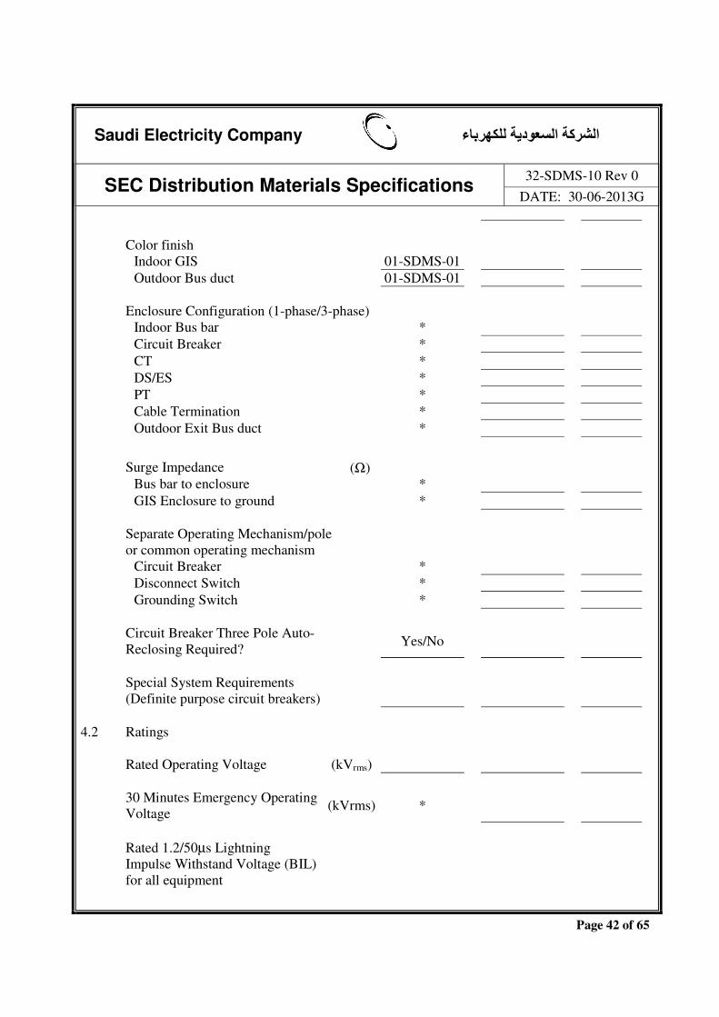
Saudi Electricity Company الشركة السعودية للكھرباء
SEC Distribution Materials Specifications 32-SDMS-10 Rev 0
DATE: 30-06-2013G
Page 42 of 65
Color finish Indoor GIS 01-SDMS-01 Outdoor Bus duct 01-SDMS-01 Enclosure Configuration (1-phase/3-phase) Indoor Bus bar * Circuit Breaker * CT * DS/ES * PT * Cable Termination * Outdoor Exit Bus duct * Surge Impedance (Ω) Bus bar to enclosure * GIS Enclosure to ground * Separate Operating Mechanism/pole
or common operating mechanism
Circuit Breaker * Disconnect Switch * Grounding Switch * Circuit Breaker Three Pole Auto-
Reclosing Required? Yes/No
Special System Requirements
(Definite purpose circuit breakers)
4.2 Ratings Rated Operating Voltage (kVrms) 30 Minutes Emergency Operating
Voltage (kVrms) *
Rated 1.2/50µs Lightning
Impulse Withstand Voltage (BIL) for all equipment

Saudi Electricity Company الشركة السعودية للكھرباء
SEC Distribution Materials Specifications 32-SDMS-10 Rev 0
DATE: 30-06-2013G
Page 43 of 65
To ground (kVpeak) * Between phases (kVpeak) * Across open contacts
(for Disconnect Switch, ES) (kVpeak) *
Rated 250/2500µs Switching
Impulse Withstand Voltage (BSL) for 380kV class equipment
To ground (kVpeak) * Between phases (kVpeak) *
Across open contacts (for Disconnect Switch, ES) (kVpeak) *
Power Frequency Withstand
Voltage for all equipment
To ground (kV rms) * Between phases (kV rms) * Across open contacts
(for Disconnect Switch, ES) (kV rms) *
Rated Continuous Current
(1250,1600,2000,2500,3150,4000A)
Indoor Bus bar (A) Circuit Breaker (A) Disconnect Switch (A) Outdoor Exit Bus duct (A) Rated Insulation Voltage of
Auxiliary Circuits (1 min.) (kV rms) *
Rated Short Circuit Withstand
Current of GIS & termination (31.5, 40, 50, 63kArms)
(kArms)
Rated Duration of Short Circuit (s) 1 Rated Peak Withstand Current (kA peak) Partial Discharge Value of GIS
Assembly at110% of Maximum (pC) *
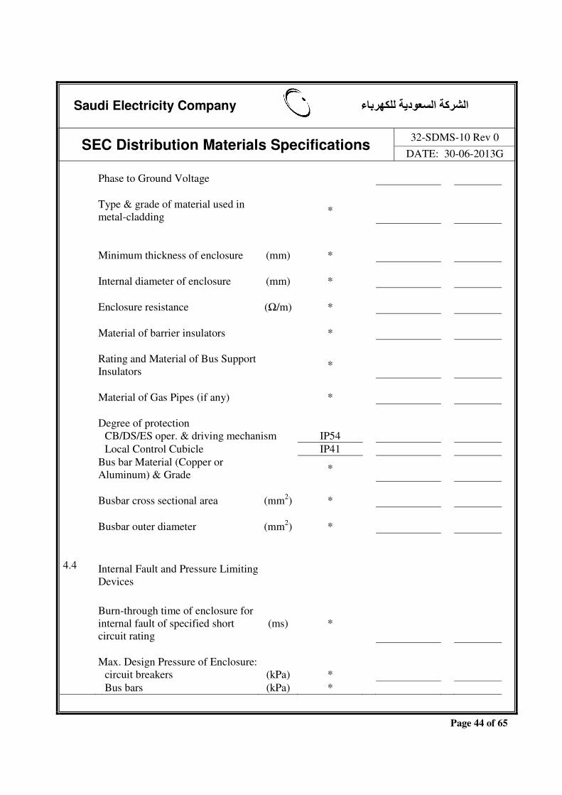
Saudi Electricity Company الشركة السعودية للكھرباء
SEC Distribution Materials Specifications 32-SDMS-10 Rev 0
DATE: 30-06-2013G
Page 44 of 65
Phase to Ground Voltage Type & grade of material used in
metal-cladding *
Minimum thickness of enclosure (mm) * Internal diameter of enclosure (mm) * Enclosure resistance (Ω/m) * Material of barrier insulators * Rating and Material of Bus Support
Insulators *
Material of Gas Pipes (if any) * Degree of protection CB/DS/ES oper. & driving mechanism IP54 Local Control Cubicle IP41 Bus bar Material (Copper or
Aluminum) & Grade *
Busbar cross sectional area (mm2) * Busbar outer diameter (mm2) *
4.4 Internal Fault and Pressure Limiting Devices
Burn-through time of enclosure for
internal fault of specified short circuit rating
(ms) *
Max. Design Pressure of Enclosure: circuit breakers (kPa) * Bus bars (kPa) *

Saudi Electricity Company الشركة السعودية للكھرباء
SEC Distribution Materials Specifications 32-SDMS-10 Rev 0
DATE: 30-06-2013G
Page 45 of 65
Other compartments & termination (Please list for each compartment)
(kPa) *
Pressure at which the pressure
relief valve (or rupture disk) shall operate in:
circuit breakers (kPa) * Bus bars (kPa) *
Other compartments & termination (Please list for each compartment)
(kPa) *
4.5 SF6 Gas System Requirements Reference Industry Standard to
which the SF6 Gas Conforms *
Rated Operating SF6 Gas Pressure
at 20°C (Please list for each compartment)
(kPa) *
Maximum Operating SF6 Gas
Pressure (Please list for each compartment)
(kPa) *
Minimum operating SF6 Gas
Pressure (Please list for each compartment)
(kPa) *
Minimum operating SF6 Gas
Density (Please list for each compartment)
(kg/m3) *
Breaker Close lockout pressure (kPa) * Breaker Trip lockout pressure (kPa) *

Saudi Electricity Company الشركة السعودية للكھرباء
SEC Distribution Materials Specifications 32-SDMS-10 Rev 0
DATE: 30-06-2013G
Page 46 of 65
Maximum Relative Leakage Rate of each Compartment per Year
(%) 0.5 Total quantity of SF6 Gas
required to fill
each breaker (kg) *
Other compartments (Please
list for each compartment) (kg) *
Volume of SF6 per Bay at rated
pressure & 20°C (Please list for each compartment)
(m3) *
Permissible Concentration of
impurities in SF6 gas in service (Please list for each compartment)
% *
4.9 Bus bar Assemblies/Exit Bus Conductor Resistance at 90ºC (µΩ/m) * Resistance of bus joints at 100Adc (µΩ) * Phase spacing for 3-phase
enclosure (mm) *
Bus bar Capacitance/Phase (µF/m) * % Overload capacity and duration (s) *
4.10 Circuit Breakers Type and designation number *
Maximum DC resistance of the power carrying circuit from terminal to terminal of CB
(Ω) *
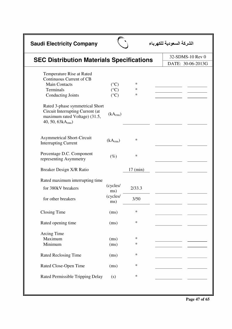
Saudi Electricity Company الشركة السعودية للكھرباء
SEC Distribution Materials Specifications 32-SDMS-10 Rev 0
DATE: 30-06-2013G
Page 47 of 65
Temperature Rise at Rated Continuous Current of CB
Main Contacts (°C) * Terminals (°C) * Conducting Joints (°C) *
Rated 3-phase symmetrical Short Circuit Interrupting Current (at maximum rated Voltage) (31.5, 40, 50, 63kArms)
(kArms)
Asymmetrical Short-Circuit
Interrupting Current (kArms) *
Percentage D.C. Component
representing Asymmetry (%) *
Breaker Design X/R Ratio 17 (min) Rated maximum interrupting time for 380kV breakers (cycles/
ms) 2/33.3
for other breakers
(cycles/ms) 3/50
Closing Time (ms) * Rated opening time (ms) * Arcing Time Maximum (ms) * Minimum (ms) * Rated Reclosing Time (ms) * Rated Close-Open Time (ms) * Rated Permissible Tripping Delay (s) *

Saudi Electricity Company الشركة السعودية للكھرباء
SEC Distribution Materials Specifications 32-SDMS-10 Rev 0
DATE: 30-06-2013G
Page 48 of 65
Rated Out-of-Phase breaking current capability
(kArms) *
Rated Line Charging Current
Breaking Capability (Arms)
Rated Cable Charging Current
Breaking Capability (Arms)
Rated small inductive current
breaking capability (Arms) *
Rated Reactive Current breaking
capability, if applicable (Arms) *
Rated Single Capacitor Bank
Breaking Current, if applicable (Arms) *
Rated Back-to-Back Capacitor
Bank Breaking Current, if applicable
(Arms) *
Rated Capacitor Bank In-rush
Making Current, if applicable (kApeak) *
Rated Transient Recovery
Voltage for Short Line Faults (kVpeak) *
Rated Characteristics of Short
Line Faults:
Surge Impedance (Ω) * Amplitude Constant (kV/µs kA) * R.R.R.V factor * The critical line length (L%) * First pole-to-clear factor 1.5 Rated Transient Recovery
Voltage for Terminal Fault (kVpeak) *
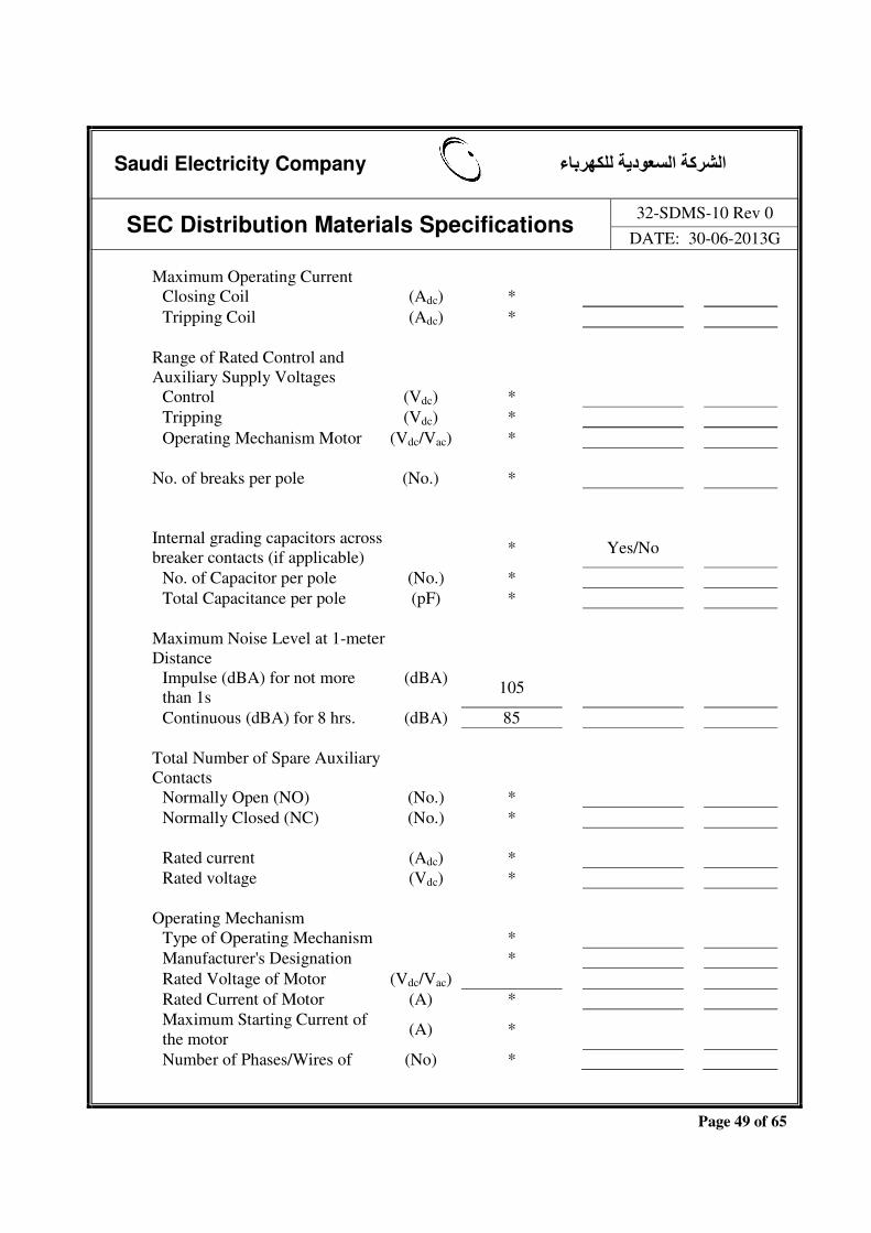
Saudi Electricity Company الشركة السعودية للكھرباء
SEC Distribution Materials Specifications 32-SDMS-10 Rev 0
DATE: 30-06-2013G
Page 49 of 65
Maximum Operating Current Closing Coil (Adc) * Tripping Coil (Adc) * Range of Rated Control and
Auxiliary Supply Voltages
Control (Vdc) * Tripping (Vdc) * Operating Mechanism Motor (Vdc/Vac) * No. of breaks per pole (No.) * Internal grading capacitors across
breaker contacts (if applicable) * Yes/No
No. of Capacitor per pole (No.) * Total Capacitance per pole (pF) * Maximum Noise Level at 1-meter
Distance
Impulse (dBA) for not more than 1s
(dBA) 105
Continuous (dBA) for 8 hrs. (dBA) 85 Total Number of Spare Auxiliary
Contacts
Normally Open (NO) (No.) * Normally Closed (NC) (No.) * Rated current (Adc) * Rated voltage (Vdc) * Operating Mechanism Type of Operating Mechanism * Manufacturer's Designation * Rated Voltage of Motor (Vdc/Vac) Rated Current of Motor (A) *
Maximum Starting Current of the motor
(A) *
Number of Phases/Wires of (No) *

Saudi Electricity Company الشركة السعودية للكھرباء
SEC Distribution Materials Specifications 32-SDMS-10 Rev 0
DATE: 30-06-2013G
Page 50 of 65
Motor Space Heaters Voltage (Vrms) 400Vac Wattage (W) * Spring-Operated Mechanism (If
applicable)
Number of close-open operations that can be performed by the mechanism before having recharge
*
Time required to charge the closing spring
(s) *
Pneumatic or Hydraulic Mechanism
(If applicable)
Number of close-open operations that can be performed by the energy in the stored energy device on each circuit breaker starting at the normal working pressure and without replenishing the energy
*
Rated value of pressure at which the circuit breaker will operate satisfactorily
(MPa) *
Range of pressure within which the circuit breaker will operate satisfactorily
(MPa) *
Time required for the motor to charge from trip lockout to normal operating pressure
(minutes/s)
*
Opening pressure of Safety Valve (Mpa) *
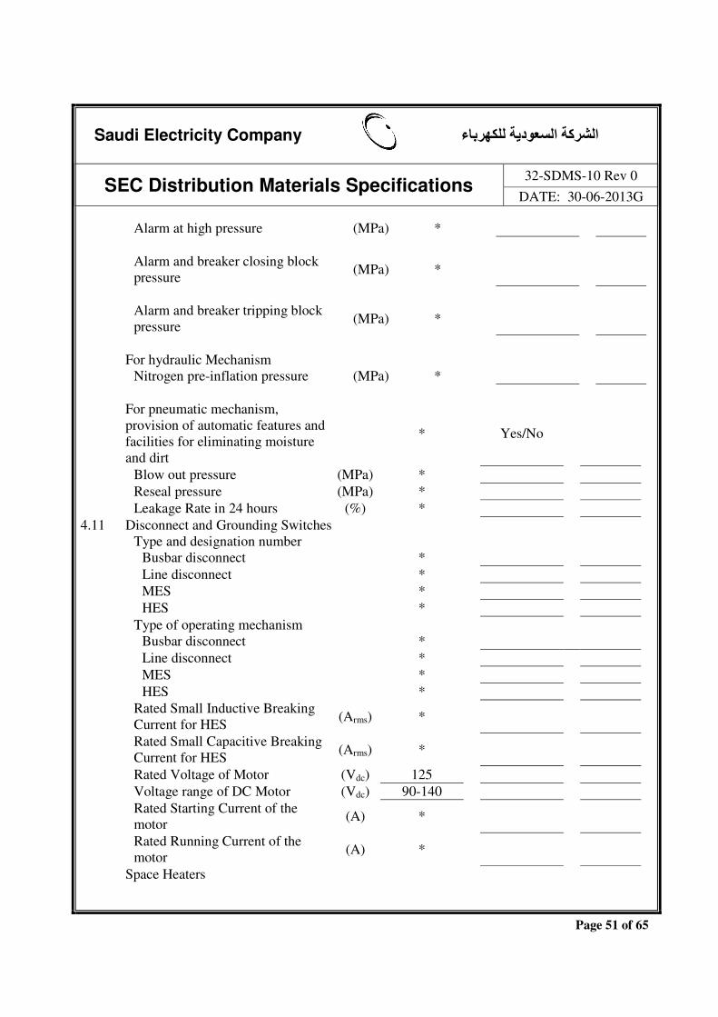
Saudi Electricity Company الشركة السعودية للكھرباء
SEC Distribution Materials Specifications 32-SDMS-10 Rev 0
DATE: 30-06-2013G
Page 51 of 65
Alarm at high pressure (MPa) *
Alarm and breaker closing block pressure
(MPa) *
Alarm and breaker tripping block pressure (MPa) *
For hydraulic Mechanism Nitrogen pre-inflation pressure (MPa) * For pneumatic mechanism,
provision of automatic features and facilities for eliminating moisture and dirt
* Yes/No
Blow out pressure (MPa) * Reseal pressure (MPa) * Leakage Rate in 24 hours (%) * 4.11 Disconnect and Grounding Switches Type and designation number Busbar disconnect * Line disconnect * MES * HES * Type of operating mechanism Busbar disconnect * Line disconnect * MES * HES *
Rated Small Inductive Breaking Current for HES (Arms) *
Rated Small Capacitive Breaking Current for HES (Arms) *
Rated Voltage of Motor (Vdc) 125 Voltage range of DC Motor (Vdc) 90-140 Rated Starting Current of the
motor (A) *
Rated Running Current of the motor (A) *
Space Heaters

Saudi Electricity Company الشركة السعودية للكھرباء
SEC Distribution Materials Specifications 32-SDMS-10 Rev 0
DATE: 30-06-2013G
Page 52 of 65
Voltage (Vrms) 400Vac Wattage (W) * Total Number of Spare Auxiliary Contacts Normally Open (NO) (No.) * Normally Closed (NC) (No.) * Rated breaking current (Adc) * Rated voltage (Vdc) * Opening Time max./min. (s) * Closing Time max./min. (s) * Diameter of inspection windows (mm) 50 Main contact resistance (µΩ) * 4.12 Current Transformers (Add
additional sheets if required)
Type and designation number * Type of Secondary Winding
Insulation and Class *
Rated Primary current (Arms) Rated Secondary Current (Arms) (1 or 5) Continuous Thermal Current
Rating Factor
Multi ratio CTs Single ratio CTs Rated Short Time Withstand Current
Thermal, Ith (31.5, 40, 50, 63 kArms)
(kArms) *
Dynamic (kApeak) 2.6xIth Short time thermal current duration (s) * Rated primary short circuit
current, IPSC (kArms) *

Saudi Electricity Company الشركة السعودية للكھرباء
SEC Distribution Materials Specifications 32-SDMS-10 Rev 0
DATE: 30-06-2013G
Page 53 of 65
Permissible Temperature Rise (°C) * CTs external to the GIS enclosure? * Yes/No Number of CTs and their locations * Number of Metering cores per CT (No.) Number of Relaying cores per CT (No.) Core No. 1 /2 /3 Purpose (Relaying or Metering) / / Type of Protection (back-up/
differential/distance protection etc) / /
Current Ratio at specified tap / / Accuracy Class / / Burden (VA)/Resistive burden -Rb
(Ω) *
Secondary winding Resistance at
20ºC, Rct (Ω) */ * / *
For class TPS CTs per IEC Rated symmetrical short circuit
current factor –KSSC */ * / *
Dimensioning parameter -K */ * / *
Excitation limiting secondary Voltage, Ual
(V) */ * / *
Accuracy limiting secondary exciting Current, Ial
(mA) */ * / *

Saudi Electricity Company الشركة السعودية للكھرباء
SEC Distribution Materials Specifications 32-SDMS-10 Rev 0
DATE: 30-06-2013G
Page 54 of 65
Secondary excitation current, Imag at half excitation limiting secondary voltage
(mA) */ * / *
For class C or K CTs per IEEE /
CTs per IEC
Magnetizing current, Imag (mA) */ * / * Knee point voltage (Vk) Secondary limiting e.m.f (V) */ * / * 4.13 Potential Transformers Type and designation number * Type of Insulation and Class * Winding Material (Cu) Cu Voltage Ratio (s) * Rated Voltage Factor with Time (s) Rated Secondary Voltage (Vrms)
Rated Secondary Tap (if required) Voltage (Vrms)
Secondary Fuse/MCB Rating (A) * Continuous Thermal Burden (VA) * Number of Metering cores (No) Number of Relaying cores (No) Relaying Core(s)
Accuracy class (3P per IEC or 1.2R per ANSI)
Burden of each core (VA)

Saudi Electricity Company الشركة السعودية للكھرباء
SEC Distribution Materials Specifications 32-SDMS-10 Rev 0
DATE: 30-06-2013G
Page 55 of 65
Metering Core(s)
Accuracy Class (0.2 or 0.5 per IEC or 0.3 per ANSI) Accuracy class to be selected as per Project/ Design requirement
Burden of each core (VA) Maximum Partial Discharge phase
to ground
at maximum rated voltage (pC) * at 1.2 x maximum rated voltage/√3 (pC) * 4.15 Sealing end box for Underground
Cable Termination
To be supplied by GIS manufacturer Yes/No Type of Cable XLPE Type and designation number * Type of termination (Indoor or Outdoor) * Termination Class (per IEEE 48 or eqv.) 1 Conductor Size (mm2) Number of Cables per Phase Overall Cable Diameter (mm) Maximum Design Voltage to
ground
at 69kV (kVrms) 44 Continuous Current Carrying
Capability (Arms)

Saudi Electricity Company الشركة السعودية للكھرباء
SEC Distribution Materials Specifications 32-SDMS-10 Rev 0
DATE: 30-06-2013G
Page 56 of 65
Maximum Operating Temperature For XLPE cable termination (ºC) 90 Emergency Operating Temperature For XLPE cable termination (ºC) Rated Internal Pressure of SF6 gas For XLPE cable termination (kPa) Net Weight (kg) * Shield Break Insulation
Withstand (kVpeak)
Non-linear resistance/SVL ratings (kV,
kJ/kV) *
Reference Manufacturing Standard Detail drawing showing all
components and their dimension to be provided?
Yes/No
4.16 SF6-to-Air Overhead Line Termination Yes/No Type and designation number * Phase-to-Phase Clearance (mm) Height of Live Parts above
ground (mm) *
Creepage Distance (mm) * Color of Bushing Brown Cantilever loading (kN) * Mounting details Bolt circle diameter of the flange (mm) *

Saudi Electricity Company الشركة السعودية للكھرباء
SEC Distribution Materials Specifications 32-SDMS-10 Rev 0
DATE: 30-06-2013G
Page 57 of 65
No. of bolts (No.) * Size of bolts (mm) * Terminals Type * Size (mm2) * No. of holes (if applicable) (No.) * Surge Impedance overhead line to
ground (Ω) *
Maximum Design Voltage to ground at 69kV (kVrms) 44 Continuous Current Carrying
Capability (Arms)
Reference Manufacturing Standard * Detail drawing showing all
components and their dimension to be provided?
Yes/No
4.17 SF6-to-Oil Transformer/Reactor
Termination
To be supplied by GIS manufacturer Yes/No Type and designation number * Mounting details Bolt circle diameter of the flange (mm) * No. of bolts (No.) * Size of bolts (mm) * Terminal Type * Size (mm2) * No. of holes (if applicable) (No.) * Maximum Design Voltage to

Saudi Electricity Company الشركة السعودية للكھرباء
SEC Distribution Materials Specifications 32-SDMS-10 Rev 0
DATE: 30-06-2013G
Page 58 of 65
ground at 69kV (kVrms) 44 Continuous Current Carrying Capability
(Arms)
Non-linear resisance/SVL ratings (kV,
kJ/kV) *
Reference Manufacturing Standard * Detail drawing showing all components and
their dimension to be provided? Yes/No
4.18 Gas Insulated Surge Arresters Gas Insulated Surge Arresters required? Yes/No Equipment to be protected Type and designation number * BIL of Equipment to be protected System Neutral Grounding at Arrester Point
of Installation (Effectively, Non-Effectively grounded)
Rated voltage (kVrms) MCOV (kVrms) Line Discharge Class Nominal Discharge Current
(Lightning Impulse Classifying Current) with8/20 µs Waveform
(kApeak)
High Current Impulse Capability
with 4/10 µs Waveform (kApeak) *
Long Duration Wave Withstand Capability
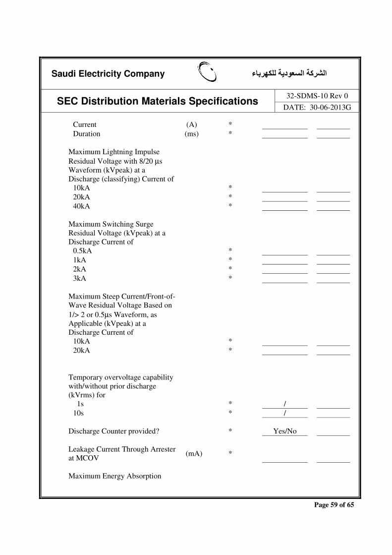
Saudi Electricity Company الشركة السعودية للكھرباء
SEC Distribution Materials Specifications 32-SDMS-10 Rev 0
DATE: 30-06-2013G
Page 59 of 65
Current (A) * Duration (ms) * Maximum Lightning Impulse
Residual Voltage with 8/20 µs Waveform (kVpeak) at a Discharge (classifying) Current of
10kA * 20kA * 40kA * Maximum Switching Surge
Residual Voltage (kVpeak) at a Discharge Current of
0.5kA * 1kA * 2kA * 3kA * Maximum Steep Current/Front-of-
Wave Residual Voltage Based on 1/> 2 or 0.5µs Waveform, as Applicable (kVpeak) at a Discharge Current of
10kA * 20kA * Temporary overvoltage capability
with/without prior discharge (kVrms) for
1s * / 10s * / Discharge Counter provided? * Yes/No Leakage Current Through Arrester
at MCOV (mA) *
Maximum Energy Absorption
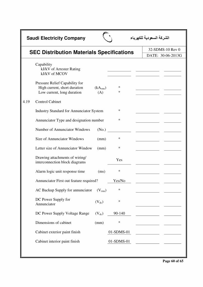
Saudi Electricity Company الشركة السعودية للكھرباء
SEC Distribution Materials Specifications 32-SDMS-10 Rev 0
DATE: 30-06-2013G
Page 60 of 65
Capability kJ/kV of Arrester Rating kJ/kV of MCOV Pressure Relief Capability for High current, short duration (kArms) * Low current, long duration (A) * 4.19 Control Cabinet Industry Standard for Annunciator System * Annunciator Type and designation number * Number of Annunciator Windows (No.) Size of Annunciator Windows (mm) * Letter size of Annunciator Window (mm) * Drawing attachments of wiring/
interconnection block diagrams Yes
Alarm logic unit response time (ms) * Annunciator First out feature required? Yes/No AC Backup Supply for annunciator (Vrms) * DC Power Supply for
Annunciator (Vdc) *
DC Power Supply Voltage Range (Vdc) 90-140 Dimensions of cabinet (mm) * Cabinet exterior paint finish 01-SDMS-01 Cabinet interior paint finish 01-SDMS-01

Saudi Electricity Company الشركة السعودية للكھرباء
SEC Distribution Materials Specifications 32-SDMS-10 Rev 0
DATE: 30-06-2013G
Page 61 of 65
4.20 Substation Automation Systems Yes/No IEDs IED type/ Model Number * Make and country of origin *
Functions included in thestandard configuration *
Support functions * Supported tools * Optional functions *
Number of physical connection in the standard configuration (analog and binary)
(No.) *
Supported communication interfaces and protocols
*
Auxiliary Power (Vdc/Vac)
Mounting
Display * Operating temperature (ºC) * 4.21 On line PD monitoring Yes/No Internal Sensors Sensitivity (pC) Output (dBm)
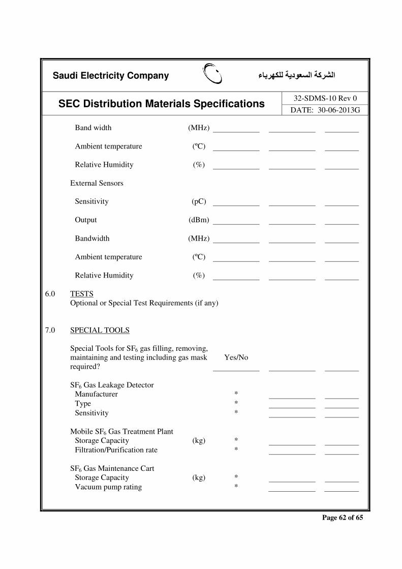
Saudi Electricity Company الشركة السعودية للكھرباء
SEC Distribution Materials Specifications 32-SDMS-10 Rev 0
DATE: 30-06-2013G
Page 62 of 65
Band width (MHz) Ambient temperature (ºC) Relative Humidity (%) External Sensors Sensitivity (pC) Output (dBm) Bandwidth (MHz) Ambient temperature (ºC) Relative Humidity (%) 6.0 TESTS Optional or Special Test Requirements (if any)
7.0 SPECIAL TOOLS Special Tools for SF6 gas filling, removing,
maintaining and testing including gas mask required?
Yes/No
SF6 Gas Leakage Detector Manufacturer * Type * Sensitivity * Mobile SF6 Gas Treatment Plant Storage Capacity (kg) * Filtration/Purification rate * SF6 Gas Maintenance Cart Storage Capacity (kg) * Vacuum pump rating *

Saudi Electricity Company الشركة السعودية للكھرباء
SEC Distribution Materials Specifications 32-SDMS-10 Rev 0
DATE: 30-06-2013G
Page 63 of 65
Portable moisture analyser Portable moisture analyser * Type Designation * Range * Sensitivity * Accuracy * OTHER GENERAL INFORMATION Net weight of complete GIS with SF6 Gas (kg) * without SF6 gas (kg) * Weight of Support Structure (kg) * Weight of heaviest Shipping Unit (kg) * Weight of heaviest piece of
equipment to be handled during construction (kg) (name item)
(kg) *
Overall Height of GIS (mm) * Overall Depth of GIS (mm) * / Overall Width of GIS (mm) * / Required capacity of overhead
traveling crane, based on heaviest module to be lifted
(kg) * Yes/No
Recommended clearance for GIS On top (mm) * On all sides (mm) * Impact loading of circuit breaker
during
Opening operation (kg) *
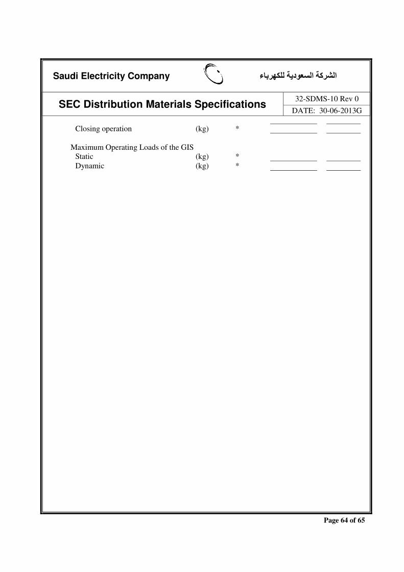
Saudi Electricity Company الشركة السعودية للكھرباء
SEC Distribution Materials Specifications 32-SDMS-10 Rev 0
DATE: 30-06-2013G
Page 64 of 65
Closing operation (kg) * Maximum Operating Loads of the GIS Static (kg) * Dynamic (kg) *

Saudi Electricity Company الشركة السعودية للكھرباء
SEC Distribution Materials Specifications 32-SDMS-10 Rev 0
DATE: 30-06-2013G
Page 65 of 65
8.0 DATA SCHEDULE
GAS INSULATED METAL CLAD 69KV SWITCHGEAR A. ADDITIONAL TECHNICAL INFORMATION OR FEATURES TO BE FURNISHED BY
SEC: B. ADDITIONAL SUPPLEMENTARY DATA OR FEATURES PROPOSED BY
BIDDER/VENDOR/SUPPLIER/CONTRACTOR:
C. OTHER PARTICULARS TO BE FILLED UP BY BIDDER/VENDOR/SUPPLIER/
CONTRACTOR:
Actual Manufacturer
of Equipment/Material Vendor/Supplier/
Contractor Name of the Company Location and address Name and Signature of authorized representative
and date Official Seal/Stamp of the Company & Date