spill prevention control and countermeasure planrehs.rutgers.edu/pdf_files/spcc plan update bl...
TRANSCRIPT
S:Projects\Rutgers\SPCC Plan/Busch_Liv\SPCC Plan update 42013
SPILL PREVENTION CONTROL AND COUNTERMEASURE PLAN
FOR RUTGERS, THE STATE UNIVERSITY OF NEW JERSEY
Busch/Livingston Campus Piscataway, New Jersey
Original Date of Plan: February 2000 Date of Last Plan Amendment/P.E. Certification: June 2003; September 2004
Date of Last Plan Review: April 2013
CERTIFICATION I hereby certify that I have examined the facility, and being familiar with the provisions of 40 CFR part 112, and have visited this facility, attest that this SPCC Plan has been prepared in accordance with good engineering practices, including consideration of applicable industry standards, and that procedures for inspection and testing have been established, and that the plan is adequate for this facility. Engineer: Registration Number: State: New Jersey Signature: Date:
SPCC Plan April 2013 Busch/Livingston Campus Page ii Rutgers, The State University of NJ
SPILL PREVENTION CONTROL AND COUNTERMEASURE COMPLIANCE INSPECTION PLAN
REVIEW PAGE In accordance with the amendments to the Oil Pollution Prevention Act promulgated under the authority of the Clean Water Act, effective August 16, 2002, and codified under 40 CFR 112, a review and evaluation of this Spill Prevention Control and Countermeasure (SPCC) Plan has been conducted. This plan must be reviewed and updated every five years for the date of the implementation of this plan (February 16, 2003). As a result of this review and evaluation, Rutgers, The State University of New Jersey (Rutgers) will amend the SPCC Plan within six months of the review (August 18, 2003) to include more effective prevention and control technology if: (1) such technology will significantly reduce the likelihood of a spill event from the facility, and (2) if such technology has been field-proven at the time of review. Any amendment to the SPCC Plan shall be certified by a Professional Engineer within six months after a change in the facility design, construction, operation, or maintenance occurs which materially affects the facility’s potential for the discharge of oil into or upon the navigable waters of the United States or adjoining shorelines.
Review Dates Signature
1.
2.
3.
4.
MANAGEMENT APPROVAL Rutgers is committed to the prevention of discharges of oil to navigable waters and the environment, and maintains the highest standards for spill prevention control and countermeasures through regular review, updating, and implementation of this SPCC Plan for the Busch/Livingston Campus.
Authorized Facility Representative:
Signature: Title:
Department:
SPCC Plan April 2013 Busch/Livingston Campus Page iii Rutgers, The State University of NJ
TABLE OF CONTENTS
TABLE OF CONTENTS ............................................................................................................ iii
LIST OF FIGURES .......................................................................................................................v
LIST OF TABLES .........................................................................................................................v
LIST OF ATTACHMENTS .........................................................................................................v
1. FACILITY OWNER AND OPERATOR ........................................................................1 1.1. Facility Owner, Address, and Telephone .................................................................1 1.2. Facility Operator, Address and Telephone ..............................................................1
2. FACILITY CONTACT(s) .................................................................................................1
3. FACILITY DESCRIPTION .............................................................................................1 3.1. Facility Operations ...................................................................................................1 3.2. Facility Oil Storage ..................................................................................................2 3.3. Drainage Pathways and Distance to Navigable Waters ...........................................7
3.3.1. Busch Campus .........................................................................................7 3.3.2. Livingston Campus .................................................................................8
4. SPILL HISTORY...............................................................................................................8
5. POTENTIAL SPILL PREDICTIONS .............................................................................8
6. PREVENTION MEASURES PROVIDED ...................................................................12 6.1. Summary of Spill Prevention and Control Measures ............................................12 6.2. Facility Drainage ....................................................................................................13
6.2.1. Drainage from diked storage areas ........................................................13 6.2.2. Valves used on diked area storage ........................................................13 6.2.3. Drainage systems from undiked areas ..................................................13 6.2.4. Final discharge of drainage ...................................................................14 6.2.5. Facility Drainage Systems and Equipment ...........................................14
6.3. Bulk Storage Tanks and Secondary Containment .................................................15 6.3.1. Tank compatibility with its contents .....................................................15 6.3.2. Diked area construction and containment volume for storage
tanks ......................................................................................................20 6.3.3. Diked area, inspection and drainage of rainwater .................................21 6.3.4. Corrosion protection of buried metallic storage tanks ..........................21 6.3.5. Corrosion protection of partially buried metallic tanks ........................21 6.3.6. Aboveground tank periodic integrity testing ........................................22 6.3.7. Control of leakage through internal heating coils .................................22 6.3.8. Tank installation fail-safe engineered ...................................................22 6.3.9. Observation of disposal facilities for effluent discharge.......................24

SPCC Plan April 2013 Busch/Livingston Campus Page iv Rutgers, The State University of NJ
6.3.10. Visible oil leak corrections from tank seams and gaskets .....................24 6.3.11. Appropriate position of mobile or portable oil storage tanks ...............24
6.4. Bulk Storage Piping ...............................................................................................24 6.4.1. Underground Piping ..............................................................................24 6.4.2. Provisions for piping not in service ......................................................25 6.4.3. Aboveground Piping Support ................................................................25 6.4.4. Aboveground valve and pipeline examination ......................................25 6.4.5. Aboveground piping protection from vehicular traffic .........................26
6.5. Facility Truck Unloading .......................................................................................26 6.5.1. Unloading procedures meet DOT regulations.......................................26 6.5.2. Secondary containment for tank trucks .................................................26 6.5.3. Warning or barrier system for vehicles .................................................26 6.5.4. Vehicles examined for lowermost drainage outlets before
leaving ...................................................................................................27 6.6. Inspections and Recordkeeping .............................................................................27 6.7. Site Security ...........................................................................................................27
6.7.1. Fencing ..................................................................................................27 6.7.2. Flow valves locked ................................................................................28 6.7.3. Starter controls locked...........................................................................28 6.7.4. Fill piping connections securely capped ...............................................28 6.7.5. Lighting adequate to detect spills ..........................................................28
6.8. Personnel Training and Spill Prevention Procedures.............................................29 6.8.1. Personnel instructions ...........................................................................29 6.8.2. Designated person accountable for spill prevention .............................29 6.8.3. Spill prevention briefings ......................................................................29
6.9. Spill Control Equipment ........................................................................................29 6.10. Emergency Contacts ..............................................................................................29
SPCC Plan April 2013 Busch/Livingston Campus Page v Rutgers, The State University of NJ
LIST OF FIGURES
Figure 1. Site Location Map
LIST OF TABLES
Table 1. Facility Contacts .............................................................................................................. 1
Table 2. Summary of Locations of Oil Storage at Busch Campus ................................................ 2
Table 3. Summary of Locations of Oil Storage at Livingston Campus ......................................... 6
Table 4. Spill History ..................................................................................................................... 8
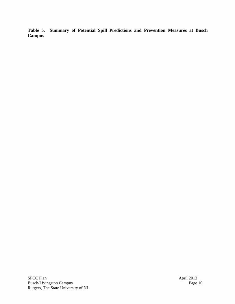
Table 5. Summary of Potential Spill Predictions and Prevention Measures at Busch Campus .. 10
Table 6. Summary of Potential Spill Predictions and Prevention Measures at Livingston Campus .......................................................................................................................... 11
Table 7. Summary of AST/UST Compatibility with Contents for Busch Campus ..................... 16
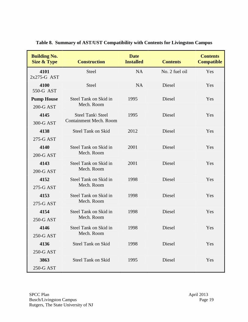
Table 8. Summary of AST/UST Compatibility with Contents for Livingston Campus .............. 19
Table 9. Summary of Fail-Safe Engineering Systems. ................................................................ 23
Table 10. Emergency Contacts .................................................................................................... 30
LIST OF ATTACHMENTS
Attachment A. Certification of the Applicability of the Substantial Harm Criteria (40 CFR 112.20)
Attachment B. Monthly Facility Inspection Checklist
Attachment C. Standard Operating Procedure - Tank Truck Unloading
SPCC Plan April 2013 Busch/Livingston Campus Page 1 Rutgers, The State University of NJ
1. FACILITY OWNER AND OPERATOR
1.1. Facility Owner, Address, and Telephone
Rutgers, The State University of New Jersey Old Queens 83 Somerset Street New Brunswick, NJ 08901-1281 1.2. Facility Operator, Address and Telephone
Rutgers, The State University of New Jersey Rutgers Environmental Health and Safety Building 4086, Livingston Campus 27 Road 1 Piscataway, New Jersey 08854-8036 (848) 445-2550 2. FACILITY CONTACT(S)
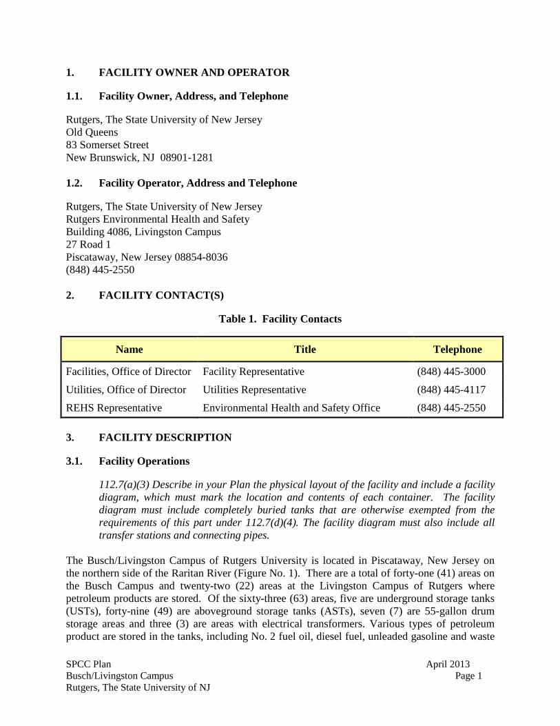
Table 1. Facility Contacts
Name Title Telephone
Facilities, Office of Director Facility Representative (848) 445-3000
Utilities, Office of Director Utilities Representative (848) 445-4117
REHS Representative Environmental Health and Safety Office (848) 445-2550 3. FACILITY DESCRIPTION
3.1. Facility Operations
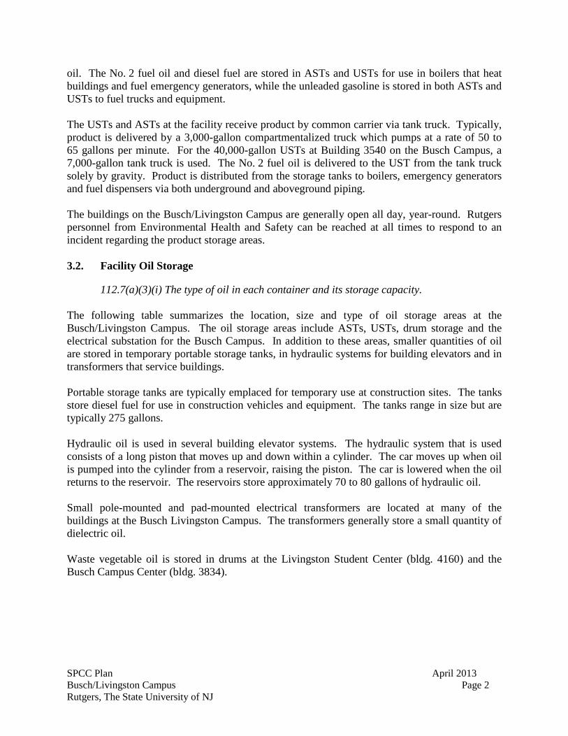
112.7(a)(3) Describe in your Plan the physical layout of the facility and include a facility diagram, which must mark the location and contents of each container. The facility diagram must include completely buried tanks that are otherwise exempted from the requirements of this part under 112.7(d)(4). The facility diagram must also include all transfer stations and connecting pipes.
The Busch/Livingston Campus of Rutgers University is located in Piscataway, New Jersey on the northern side of the Raritan River (Figure No. 1). There are a total of forty-one (41) areas on the Busch Campus and twenty-two (22) areas at the Livingston Campus of Rutgers where petroleum products are stored. Of the sixty-three (63) areas, five are underground storage tanks (USTs), forty-nine (49) are aboveground storage tanks (ASTs), seven (7) are 55-gallon drum storage areas and three (3) are areas with electrical transformers. Various types of petroleum product are stored in the tanks, including No. 2 fuel oil, diesel fuel, unleaded gasoline and waste
SPCC Plan April 2013 Busch/Livingston Campus Page 2 Rutgers, The State University of NJ
oil. The No. 2 fuel oil and diesel fuel are stored in ASTs and USTs for use in boilers that heat buildings and fuel emergency generators, while the unleaded gasoline is stored in both ASTs and USTs to fuel trucks and equipment. The USTs and ASTs at the facility receive product by common carrier via tank truck. Typically, product is delivered by a 3,000-gallon compartmentalized truck which pumps at a rate of 50 to 65 gallons per minute. For the 40,000-gallon USTs at Building 3540 on the Busch Campus, a 7,000-gallon tank truck is used. The No. 2 fuel oil is delivered to the UST from the tank truck solely by gravity. Product is distributed from the storage tanks to boilers, emergency generators and fuel dispensers via both underground and aboveground piping. The buildings on the Busch/Livingston Campus are generally open all day, year-round. Rutgers personnel from Environmental Health and Safety can be reached at all times to respond to an incident regarding the product storage areas. 3.2. Facility Oil Storage
112.7(a)(3)(i) The type of oil in each container and its storage capacity. The following table summarizes the location, size and type of oil storage areas at the Busch/Livingston Campus. The oil storage areas include ASTs, USTs, drum storage and the electrical substation for the Busch Campus. In addition to these areas, smaller quantities of oil are stored in temporary portable storage tanks, in hydraulic systems for building elevators and in transformers that service buildings. Portable storage tanks are typically emplaced for temporary use at construction sites. The tanks store diesel fuel for use in construction vehicles and equipment. The tanks range in size but are typically 275 gallons. Hydraulic oil is used in several building elevator systems. The hydraulic system that is used consists of a long piston that moves up and down within a cylinder. The car moves up when oil is pumped into the cylinder from a reservoir, raising the piston. The car is lowered when the oil returns to the reservoir. The reservoirs store approximately 70 to 80 gallons of hydraulic oil. Small pole-mounted and pad-mounted electrical transformers are located at many of the buildings at the Busch Livingston Campus. The transformers generally store a small quantity of dielectric oil. Waste vegetable oil is stored in drums at the Livingston Student Center (bldg. 4160) and the Busch Campus Center (bldg. 3834).

SPCC Plan April 2013 Busch/Livingston Campus Page 3 Rutgers, The State University of NJ
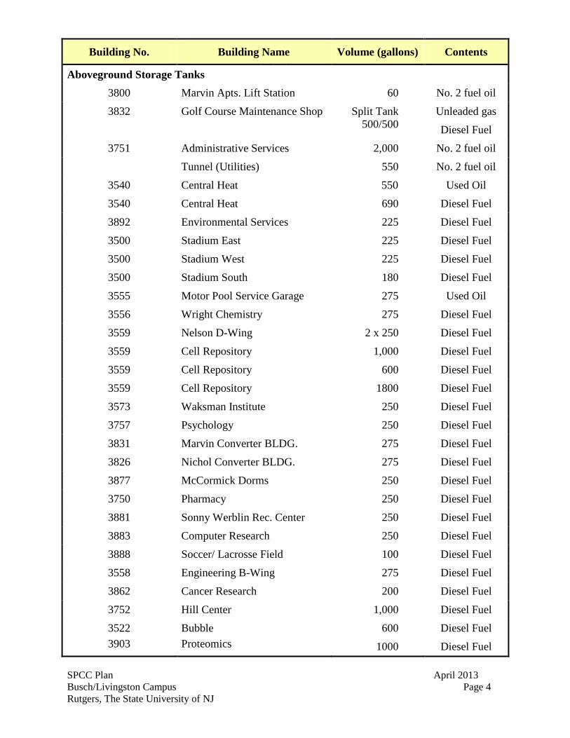
Table 2. Summary of Locations of Oil Storage at Busch Campus
SPCC Plan April 2013 Busch/Livingston Campus Page 4 Rutgers, The State University of NJ
Building No. Building Name Volume (gallons) Contents
Aboveground Storage Tanks
3800 Marvin Apts. Lift Station 60 No. 2 fuel oil
3832 Golf Course Maintenance Shop Split Tank 500/500
Unleaded gas
Diesel Fuel
3751 Administrative Services 2,000 No. 2 fuel oil
Tunnel (Utilities) 550 No. 2 fuel oil
3540 Central Heat 550 Used Oil
3540 Central Heat 690 Diesel Fuel
3892 Environmental Services 225 Diesel Fuel
3500
3500
3500
Stadium East
Stadium West
Stadium South
225
225
180
Diesel Fuel
Diesel Fuel
Diesel Fuel
3555
3556
Motor Pool Service Garage
Wright Chemistry
275
275
Used Oil
Diesel Fuel
3559 Nelson D-Wing 2 x 250 Diesel Fuel
3559
3559
Cell Repository
Cell Repository
1,000
600
Diesel Fuel
Diesel Fuel
3559
3573
Cell Repository
Waksman Institute
1800
250
Diesel Fuel
Diesel Fuel
3757 Psychology 250 Diesel Fuel
3831 Marvin Converter BLDG. 275 Diesel Fuel
3826 Nichol Converter BLDG. 275 Diesel Fuel
3877 McCormick Dorms 250 Diesel Fuel
3750 Pharmacy 250 Diesel Fuel
3881 Sonny Werblin Rec. Center 250 Diesel Fuel
3883 Computer Research 250 Diesel Fuel
3888 Soccer/ Lacrosse Field 100 Diesel Fuel
3558 Engineering B-Wing 275 Diesel Fuel
3862 Cancer Research 200 Diesel Fuel
3752 Hill Center 1,000 Diesel Fuel
3522 3903
Bubble Proteomics
600
1000
Diesel Fuel
Diesel Fuel
SPCC Plan April 2013 Busch/Livingston Campus Page 5 Rutgers, The State University of NJ
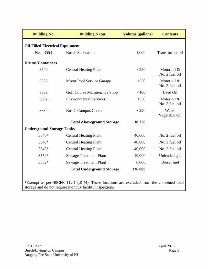
Building No. Building Name Volume (gallons) Contents
Oil-Filled Electrical Equipment
Near 3553 Busch Substation 1,000 Transformer oil
Drums/Containers
3540 Central Heating Plant <550 Motor oil & No. 2 fuel oil
3555 Motor Pool Service Garage <550 Motor oil & No. 2 fuel oil
3832 Golf Course Maintenance Shop <100 Used Oil
3892 Environmental Services <550 Motor oil & No. 2 fuel oil
3834 Busch Campus Center <220 Waste Vegetable Oil
Total Aboveground Storage 18,350
Underground Storage Tanks
3540* Central Heating Plant 40,000 No. 2 fuel oil
3540* Central Heating Plant 40,000 No. 2 fuel oil
3540* Central Heating Plant 40,000 No. 2 fuel oil
3552* Sewage Treatment Plant 10,000 Unleaded gas
3552* Sewage Treatment Plant 6,000 Diesel fuel
Total Underground Storage 136,000
*Exempt as per 40CFR 112.1 (d) (4). These locations are excluded from the combined total storage and do not require monthly facility inspections.
SPCC Plan April 2013 Busch/Livingston Campus Page 6 Rutgers, The State University of NJ
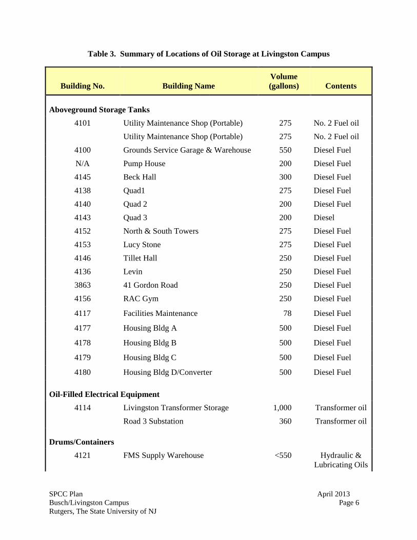
Table 3. Summary of Locations of Oil Storage at Livingston Campus
Building No. Building Name Volume (gallons) Contents
Aboveground Storage Tanks
4101 Utility Maintenance Shop (Portable)
Utility Maintenance Shop (Portable)
275
275
No. 2 Fuel oil
No. 2 Fuel oil
4100 Grounds Service Garage & Warehouse 550 Diesel Fuel
N/A Pump House 200 Diesel Fuel
4145 Beck Hall 300 Diesel Fuel
4138 Quad1 275 Diesel Fuel
4140 Quad 2 200 Diesel Fuel
4143 Quad 3 200 Diesel
4152 North & South Towers 275 Diesel Fuel
4153 Lucy Stone 275 Diesel Fuel
4146 Tillet Hall 250 Diesel Fuel
4136 Levin 250 Diesel Fuel
3863 41 Gordon Road 250 Diesel Fuel
4156 RAC Gym 250 Diesel Fuel
4117 Facilities Maintenance 78 Diesel Fuel
4177 Housing Bldg A 500 Diesel Fuel
4178 Housing Bldg B 500 Diesel Fuel
4179 Housing Bldg C 500 Diesel Fuel
4180 Housing Bldg D/Converter 500 Diesel Fuel
Oil-Filled Electrical Equipment
4114 Livingston Transformer Storage 1,000 Transformer oil
Road 3 Substation 360 Transformer oil
Drums/Containers
4121 FMS Supply Warehouse <550 Hydraulic & Lubricating Oils
SPCC Plan April 2013 Busch/Livingston Campus Page 7 Rutgers, The State University of NJ
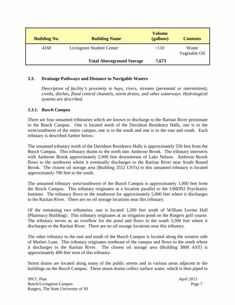
Building No. Building Name Volume (gallons) Contents
4160 Livingston Student Center <110 Waste Vegetable Oil
Total Aboveground Storage 7,673 3.3. Drainage Pathways and Distance to Navigable Waters
Description of facility’s proximity to bays, rivers, streams (perennial or intermittent), creeks, ditches, flood control channels, storm drains, and other waterways. Hydrological systems are described.
3.3.1. Busch Campus
There are four unnamed tributaries which are known to discharge to the Raritan River proximate to the Busch Campus. One is located north of the Davidson Residence Halls, one is to the west/southwest of the entire campus, one is to the south and one is to the east and south. Each tributary is described further below. The unnamed tributary north of the Davidson Residence Halls is approximately 550 feet from the Busch Campus. This tributary drains to the north into Ambrose Brook. The tributary intersects with Ambrose Brook approximately 2,000 feet downstream of Lake Nelson. Ambrose Brook flows to the northwest where it eventually discharges to the Raritan River near South Bound Brook. The closest oil storage area (Building 3552 USTs) to this unnamed tributary is located approximately 700 feet to the south. The unnamed tributary west/southwest of the Busch Campus is approximately 1,000 feet from the Busch Campus. This tributary originates at a location parallel to the UMDNJ Psychiatric Institute. The tributary flows to the southwest for approximately 5,000 feet where it discharges to the Raritan River. There are no oil storage locations near this tributary. Of the remaining two tributaries, one is located 1,200 feet south of William Levine Hall (Pharmacy Building). This tributary originates at an irrigation pond on the Rutgers golf course. The tributary serves as an overflow for the pond and flows to the south 3,500 feet where it discharges to the Raritan River. There are no oil storage locations near this tributary. The other tributary to the east and south of the Busch Campus is located along the western side of Metlars Lane. This tributary originates northeast of the campus and flows to the south where it discharges to the Raritan River. The closest oil storage area (Building 3800 AST) is approximately 400 feet west of this tributary. Storm drains are located along many of the public streets and in various areas adjacent to the buildings on the Busch Campus. These storm drains collect surface water, which is then piped to
SPCC Plan April 2013 Busch/Livingston Campus Page 8 Rutgers, The State University of NJ
the Piscataway/Edison storm sewer system. The storm sewer system eventually discharges to the Raritan River. Besides the small irrigation pond on the Rutgers golf course, there is only one other surface water body on the Busch Campus. A small lake is located immediately east of the Davidson Residence Halls. The lake collects surface water from adjacent areas of the campus. The closest oil storage area (Building 3552 USTs) is located approximately 100 feet to the west. 3.3.2. Livingston Campus
There is one unnamed tributary which discharges to the Raritan River proximate to the Livingston Campus. The unnamed tributary is located approximately 400 feet southwest of Building 4111. This tributary flows to the south into a natural but unnamed lake in Johnson Park. The lake also contains an outfall to the Raritan River. The closest oil storage area (Building 4117 AST) is located approximately 1,500 feet to the northeast. Storm drains are located along many of the streets and in various areas adjacent to the buildings on the Livingston Campus. These storm drains collect surface water, which is then piped to the Piscataway/Edison storm sewer system. 4. SPILL HISTORY
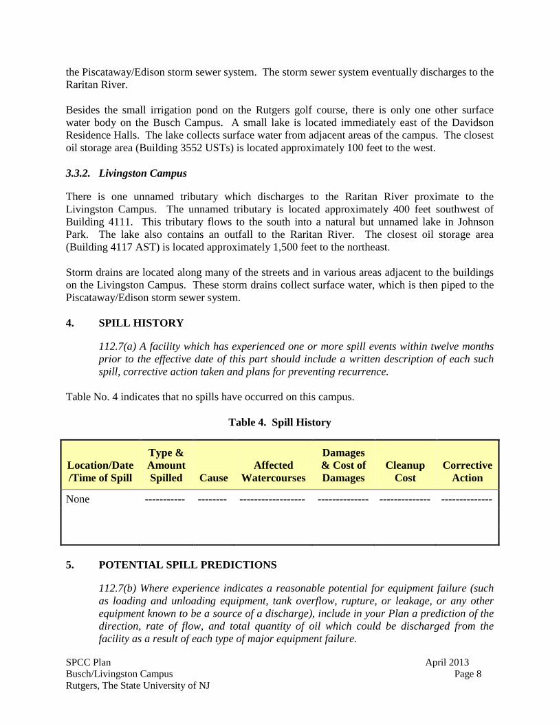
112.7(a) A facility which has experienced one or more spill events within twelve months prior to the effective date of this part should include a written description of each such spill, corrective action taken and plans for preventing recurrence.
Table No. 4 indicates that no spills have occurred on this campus.
Table 4. Spill History
Location/Date/Time of Spill
Type & Amount Spilled Cause
Affected Watercourses
Damages & Cost of Damages
Cleanup Cost
Corrective Action
None ----------- -------- ------------------ -------------- -------------- --------------
5. POTENTIAL SPILL PREDICTIONS
112.7(b) Where experience indicates a reasonable potential for equipment failure (such as loading and unloading equipment, tank overflow, rupture, or leakage, or any other equipment known to be a source of a discharge), include in your Plan a prediction of the direction, rate of flow, and total quantity of oil which could be discharged from the facility as a result of each type of major equipment failure.
SPCC Plan April 2013 Busch/Livingston Campus Page 9 Rutgers, The State University of NJ
Tables 5 and 6 summarize the predicted direction, rate of flow and total quantity of oil that would be discharged at storage areas where there is a reasonable potential for equipment failure, at the Busch and Livingston Campuses, respectively. In summary, the only oil storage areas where there is a potential for a discharge to a navigable waterway are at tank truck unloading areas located near storm water catch basins. There is little to no potential for a discharge to a navigable waterway at other oil storage areas, because (1) there are no ASTs without overfill protection and secondary containment located adjacent to a surface water body or storm water catch basin on either campus; and (2) all the USTs are equipped with overfill protection, leak detection and corrosion protection in accordance with N.J.A.C. 7:14B-4.
SPCC Plan April 2013 Busch/Livingston Campus Page 10 Rutgers, The State University of NJ
Table 5. Summary of Potential Spill Predictions and Prevention Measures at Busch Campus

SPCC Plan April 2013 Busch/Livingston Campus Page 11 Rutgers, The State University of NJ
Table 6. Summary of Potential Spill Predictions and Prevention Measures at Livingston Campus
SPCC Plan April 2013 Busch/Livingston Campus Page 12 Rutgers, The State University of NJ
6. PREVENTION MEASURES PROVIDED
6.1. Summary of Spill Prevention and Control Measures
112.7(c) Provide appropriate containment and/or diversionary structures or equipment to prevent a discharge as described in 112.1(b). The entire containment system, including walls and floor, must be capable of containing oil and must be constructed so that any discharge from a primary containment system, such as a tank or pipe, will not escape the containment system before clean up occurs. At a minimum, you must use one of the following prevention systems or its equivalent: (1) for onshore facilities: (i) Dikes, berms or retaining walls sufficiently impervious to contain oil; (ii) Curbing; (iii) Culverting, gutters or other drainage systems; (iv) Weirs, booms or other barriers; (v) Spill diversion ponds; (vi) Retention ponds, or; (vii) Sorbent materials. (2) Offshore facilities: (i) Curbing, drip pans, or; (ii) Sumps and collection systems.
Tables 5 and 6 summarize the spill prevention and control measures that are in-place to minimize the potential for equipment failure at the Busch and Livingston Campuses, respectively. As discussed in Section 5, the only oil storage areas where there is a potential for a discharge to a navigable waterway are at tank truck unloading areas located near storm water catch basins. As such, the prevention measures provided at the facility focus on these specific storage areas. At tank truck unloading areas located adjacent to storm water catch basins, diversion booms are emplaced prior to unloading. Additionally, specific procedures and warning signs have been implemented to minimize the potential for an equipment failure or human error resulting in a discharge. When a portable storage tank is used (see Section 3.2), it is positioned to (a) prevent any spilled oil from reaching navigable waters and (b) protect the tank from periodic flooding or washout. A secondary means of containment is provided for the largest single compartment or tank. The type of secondary containment is based on the area where the portable storage tank is positioned. There are no specific secondary containment measures for the hydraulic oil in elevator systems at the Busch and Livingston Campuses. Instead, Rutgers conducts monthly inspections of the hydraulic reservoirs. There is a low potential for a discharge from a hydraulic reservoir to affect a navigable waterway at either the Busch or Livingston Campus. There are no specific secondary containment measures for transformers that service buildings at the Campuses. Rutgers personnel on a monthly and, in some instances, a quarterly frequency, inspect transformers. Additionally, in the event of a discharge of oil from a transformer, the transformer would cease function and the building would lose power. This would prompt immediate response from Rutgers personnel.
SPCC Plan April 2013 Busch/Livingston Campus Page 13 Rutgers, The State University of NJ
6.2. Facility Drainage
6.2.1. Drainage from diked storage areas
112.8(b) (1) Facility drainage. Restrain drainage from diked storage areas by valves to prevent discharge into the drainage system or facility treatment system, except where facility systems are designed to control such discharge. You may empty diked areas by pumps or ejectors; however, you must manually activate these pumps or ejectors and must inspect the condition of the accumulation before starting, to ensure no oil will be discharged.
Since the facility is a college campus and the oil storage areas are generally comprised of individual tanks at various buildings across the campus, overall facility drainage is not controlled. Instead, drainage is controlled at specific oil storage areas, where necessary to minimize the potential for a discharge to navigable water. The only AST with diked secondary containment is: the 550-gallon diesel fuel AST at Building 4100 on Livingston Campus. Precipitation is prevented from accumulating in the secondary containment dike at Building 4100 by a roofed structure. A wood structure with walls and a roof are constructed around the 550-gallon AST and dike. Therefore, provisions for draining the secondary containment dike are not provided, nor necessary. 6.2.2. Valves used on diked area storage
112.8(b) (2) Use valves of manual, open-and-closed design, for the drainage of diked areas. You may not use flapper-type drain valves to drain diked areas. If your facility drainage drains directly into a watercourse and not into an on-site wastewater treatment plant, you must inspect and may drain uncontaminated retained stormwater, as provided in paragraphs (c) (3)(ii), (iii), and (iv) of this section
This section is not applicable to this facility since there are no diked areas with manually operated ball valves. 6.2.3. Drainage systems from undiked areas
112.8(b)(3) Design facility drainage systems from undiked areas with a potential for a discharge such as where piping is located outside containment walls or where tank truck discharges may occur outside the loading area) to flow into ponds, lagoons or catchment basins, designed to retain oil or return it to the facility. You must not locate catchment basins in areas subject to periodic flooding.
All tank truck unloading areas are undiked. There are no specific drainage systems for undiked areas at either the Busch or Livingston Campuses designed to retain oil in the event of a
SPCC Plan April 2013 Busch/Livingston Campus Page 14 Rutgers, The State University of NJ
discharge from either an AST or during tanker truck unloading. However, there are only a few storage locations where there is a reasonable potential for a discharge to enter either a storm water catch basin or a surface water body. Specifically, storm water catch basins are located near the truck unloading areas at Buildings 3540, 3500, 3552, 3559, 3757, 3903 and 4141. In other areas, a discharge from an AST or during truck unloading would either flow to the ground or laterally spread across paved areas. Under this scenario, the discharge could be cleaned prior to affecting any navigable waterway or any route to a navigable waterway. To minimize the potential for a discharge to either the storm water catch basins, prevention measures are utilized at these locations during unloading. A diversion boom is placed around the catch basin or around the tanker truck prior to unloading. At the tank truck unloading area for Building 3552 and 3540, a diversion boom is placed around the tank truck. The placement of the diversion boom is designed to prevent a discharge from migrating off the asphalt driveway. 6.2.4. Final discharge of drainage
112.8(b) (4) If facility drainage is not engineered as in paragraph (b)(3), of this section, equip the final discharge of all ditches inside the facility a diversion system that would, in the event of an uncontrolled discharge, retain oil in the facility.
Rutgers does not control the final discharge of storm water from the facility. Therefore, spill prevention measures focus on areas where there is a potential for a discharge from an oil storage area reaching a storm water catch basin. Specifically, as discussed in Section 6.2.3, Rutgers utilizes diversion booms to minimize the potential for a discharge entering a catch basin. If petroleum were ever to enter the catch basin, the emergency contacts listed in Section 6.10 should be immediately contacted. 6.2.5. Facility Drainage Systems and Equipment
112.8(b)(5) Where drainage waters are treated in more than one treatment unit and such treatment is continuous, and pump transfer is needed, provide two ‘‘lift’’ pumps and permanently install at least one of these pumps. Whatever techniques are used, you must engineer facility drainage systems to prevent a discharge as described in paragraph 112.1(b) in case there is an equipment failure or human error at the facility.
This section is not applicable to this facility since there are no facility drainage treatment systems.
SPCC Plan April 2013 Busch/Livingston Campus Page 15 Rutgers, The State University of NJ
6.3. Bulk Storage Tanks and Secondary Containment
6.3.1. Tank compatibility with its contents
112.8(c) (1) Bulk storage containers. Not use a container for the storage of oil unless its material and construction are compatible with the material stored and conditions of storage such as pressure and temperature.
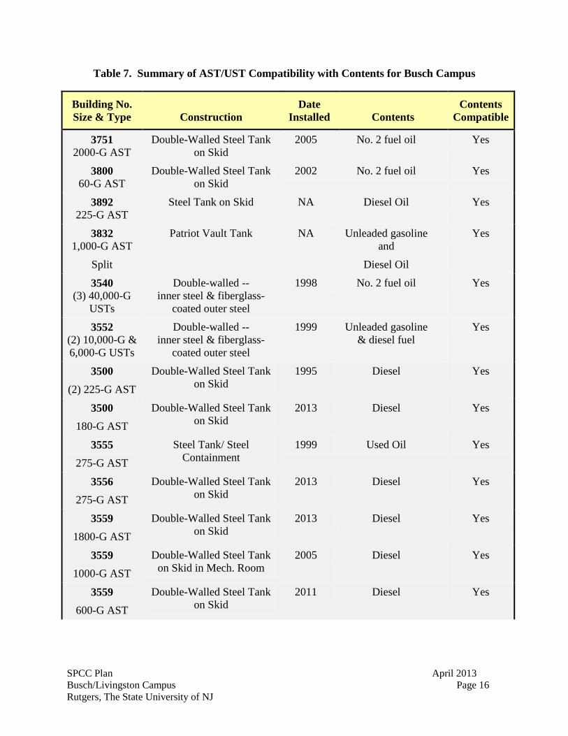
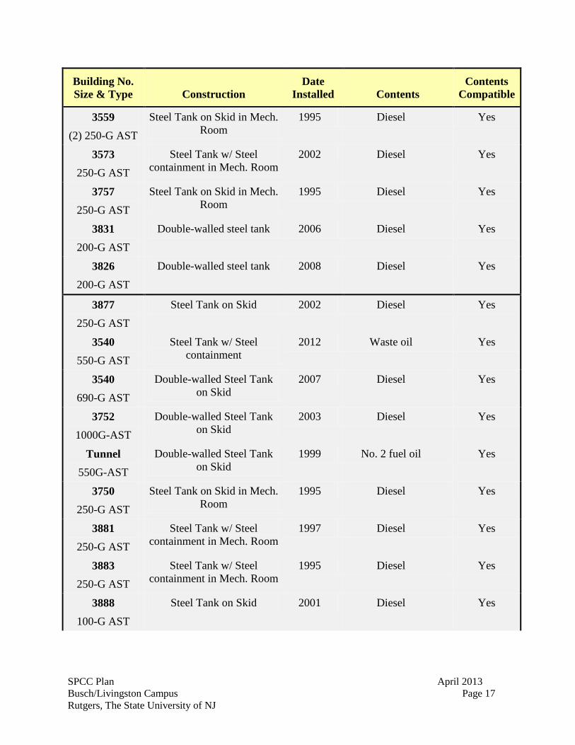
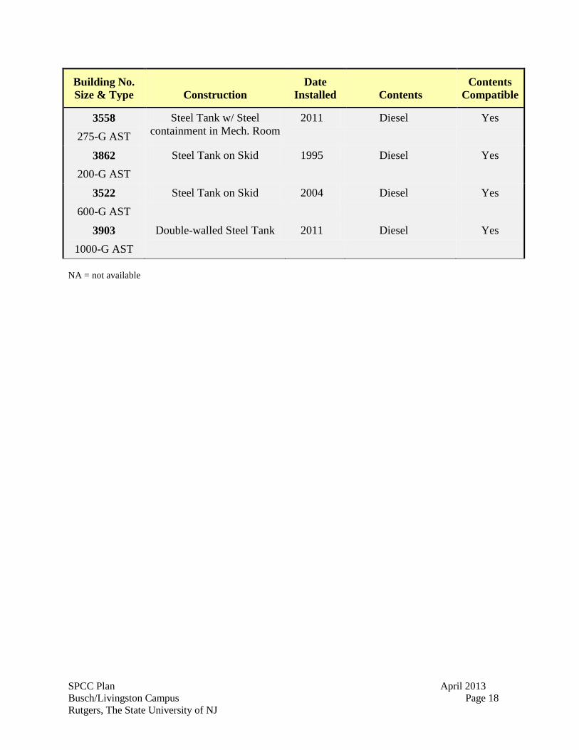
The material and construction of all USTs is compatible with both the type of oil stored and the conditions of oil storage as summarized in Tables 7 and 8 below.
SPCC Plan April 2013 Busch/Livingston Campus Page 16 Rutgers, The State University of NJ
Table 7. Summary of AST/UST Compatibility with Contents for Busch Campus
Building No. Size & Type
Construction
Date Installed
Contents
Contents Compatible
3751 2000-G AST
Double-Walled Steel Tank on Skid
2005 No. 2 fuel oil Yes
3800 60-G AST
Double-Walled Steel Tank on Skid
2002 No. 2 fuel oil Yes
3892 225-G AST
Steel Tank on Skid NA Diesel Oil Yes
3832 1,000-G AST
Split
Patriot Vault Tank NA Unleaded gasoline and
Diesel Oil
Yes
3540 (3) 40,000-G
USTs
Double-walled -- inner steel & fiberglass-
coated outer steel
1998 No. 2 fuel oil Yes
3552 (2) 10,000-G & 6,000-G USTs
Double-walled -- inner steel & fiberglass-
coated outer steel
1999 Unleaded gasoline & diesel fuel
Yes
3500 (2) 225-G AST
Double-Walled Steel Tank on Skid
1995 Diesel Yes
3500 180-G AST
Double-Walled Steel Tank on Skid
2013 Diesel Yes
3555 275-G AST
Steel Tank/ Steel Containment
1999 Used Oil Yes
3556 275-G AST
Double-Walled Steel Tank on Skid
2013 Diesel Yes
3559 1800-G AST
Double-Walled Steel Tank on Skid
2013 Diesel Yes
3559 1000-G AST
Double-Walled Steel Tank on Skid in Mech. Room
2005
Diesel
Yes
3559 600-G AST
Double-Walled Steel Tank on Skid
2011 Diesel Yes
SPCC Plan April 2013 Busch/Livingston Campus Page 17 Rutgers, The State University of NJ
Building No. Size & Type
Construction
Date Installed
Contents
Contents Compatible
3559 (2) 250-G AST
Steel Tank on Skid in Mech. Room
1995 Diesel Yes
3573 250-G AST
Steel Tank w/ Steel containment in Mech. Room
2002 Diesel Yes
3757 250-G AST
Steel Tank on Skid in Mech. Room
1995 Diesel Yes
3831 200-G AST
Double-walled steel tank 2006 Diesel Yes
3826 200-G AST
Double-walled steel tank 2008 Diesel Yes
3877 250-G AST
Steel Tank on Skid 2002 Diesel Yes
3540 550-G AST
Steel Tank w/ Steel containment
2012 Waste oil Yes
3540 690-G AST
Double-walled Steel Tank on Skid
2007 Diesel Yes
3752 1000G-AST
Double-walled Steel Tank on Skid
2003 Diesel Yes
Tunnel 550G-AST
Double-walled Steel Tank on Skid
1999 No. 2 fuel oil Yes
3750 250-G AST
Steel Tank on Skid in Mech. Room
1995 Diesel Yes
3881 250-G AST
Steel Tank w/ Steel containment in Mech. Room
1997 Diesel Yes
3883 250-G AST
Steel Tank w/ Steel containment in Mech. Room
1995 Diesel Yes
3888 100-G AST
Steel Tank on Skid 2001 Diesel Yes
SPCC Plan April 2013 Busch/Livingston Campus Page 18 Rutgers, The State University of NJ
Building No. Size & Type
Construction
Date Installed
Contents
Contents Compatible
3558 275-G AST
Steel Tank w/ Steel containment in Mech. Room
2011 Diesel Yes
3862 200-G AST
Steel Tank on Skid 1995 Diesel Yes
3522 600-G AST
Steel Tank on Skid 2004
Diesel Yes
3903 1000-G AST
Double-walled Steel Tank 2011 Diesel Yes
NA = not available
SPCC Plan April 2013 Busch/Livingston Campus Page 19 Rutgers, The State University of NJ
Table 8. Summary of AST/UST Compatibility with Contents for Livingston Campus
Building No. Size & Type
Construction
Date Installed
Contents
Contents Compatible
4101 2x275-G AST
Steel NA No. 2 fuel oil Yes
4100 550-G AST
Steel NA Diesel Yes
Pump House 200-G AST
Steel Tank on Skid in Mech. Room
1995 Diesel Yes
4145 300-G AST
Steel Tank\ Steel Containment Mech. Room
1995 Diesel Yes
4138 275-G AST
Steel Tank on Skid 2012 Diesel Yes
4140 200-G AST
Steel Tank on Skid in Mech. Room
2001 Diesel Yes
4143 200-G AST
Steel Tank on Skid in Mech. Room
2001 Diesel Yes
4152 275-G AST
Steel Tank on Skid in Mech. Room
1998 Diesel Yes
4153 275-G AST
Steel Tank on Skid in Mech. Room
1998 Diesel Yes
4154 250-G AST
Steel Tank on Skid in Mech. Room
1998 Diesel Yes
4146 250-G AST
Steel Tank on Skid in Mech. Room
1998 Diesel Yes
4136 250-G AST
Steel Tank on Skid 1998 Diesel Yes
3863 250-G AST
Steel Tank on Skid 1995 Diesel Yes

SPCC Plan April 2013 Busch/Livingston Campus Page 20 Rutgers, The State University of NJ
Building No. Size & Type
Construction
Date Installed
Contents
Contents Compatible
4156 250-G AST
Steel Tank on Skid in Mech. Room
1998
Diesel
Yes
4117
78-G AST Steel Tank on Skid in
Mech. Room 2011
Diesel
Yes
4177
500-G AST Steel Tank on Skid 2012 Diesel
Yes
4178
500-G AST Steel Tank on Skid 2012 Diesel
Yes
4179 500-G AST
Steel Tank on Skid 2012 Diesel
Yes
4180 500-G AST
Steel Tank on Skid 2012 Diesel Yes
NA = not available 6.3.2. Diked area construction and containment volume for storage tanks
112.8(c)(2) Construct all bulk storage tank installations so that you provide a secondary means of containment for the entire contents of the largest single tank plus sufficient freeboard to allow for precipitation. You must ensure diked areas are sufficiently impervious to contain discharges oil. Dikes, containment curbs, and pits are commonly employed for this purpose. You may use an alternative system consisting of a drainage trench enclosure that must be arranged so that a discharge will be safely confined in an in facility catchment basin or holding pond.
A secondary containment structure is provided for the ASTs at Buildings 3832, 3500, 3752, 4101 and 4100. The 550-gallon diesel fuel AST at Building 4100 is located atop a concrete slab surrounded by concrete walls for containment. The concrete is sufficiently impervious to retain the contents of the AST in the event of a failure. Secondary containment is designed to hold the entire contents of the AST. The AST is covered with a roof, hence, additional volume for precipitation is not provide nor necessary. The containment area will hold 605 gallons. A secondary containment structure is provided for ASTs at 3832, 3751, 3540, 3500, 3522, 3556, 3559, 3572, 3831, 3826, 3888, 3862, 3903, 4101 (two portable ASTs), 4138, 4177, 4178, 4179, and 4180. The secondary containment is designed to hold the entire contents of the ASTs in the
SPCC Plan April 2013 Busch/Livingston Campus Page 21 Rutgers, The State University of NJ
event of a failure. Additional volume for precipitation is not necessary since the containment structure is fully enclosed. All other ASTs are located within buildings and/ or mechanical spaces whereas the building serves as containment. 6.3.3. Diked area, inspection and drainage of rainwater
112.8(c)(3) Not allow drainage of uncontaminated rainwater from the diked area into a storm drain or discharge of an effluent into an open water course, lake, or pond, or bypassing the treatment facility system unless you: (i) Normally keep the bypass valve sealed closed. (ii) Inspect the retained rainwater to ensure its presence will not cause a discharge as described in paragraph 112.1(b). (iii) Open the bypass valve and reseal it following drainage under responsible supervision. (iv) Keep adequate records of such events, for example, any records required under permits issued in accordance with paragraph 122.41(j)(2) and 122.41(m)(3) of this chapter.
There are no diked storage areas where precipitation accumulates and is manually drained. 6.3.4. Corrosion protection of buried metallic storage tanks
112.8(c)(4) Protect any completely buried metallic storage tanks installed after January 10, 1974 from corrosion by coatings or cathodic protection compatible with local soil conditions. You must regularly leak test such completely buried metallic storage tanks.
All USTs contain corrosion protection in accordance with N.J.A.C. 7:14-4.2 and 40 CFR 280. The UST systems (i.e., tank and piping), including the three (3) 40,000-gallon No.2 fuel oil USTs at Building 3540 and the 10,000-gallon unleaded gasoline and 6,000-gallon diesel fuel USTs at Building 3552, are double-walled, consisting of an inner steel tank surrounded by a fiberglass-coated outer steel tank with interstitial monitoring. The tanks were designed and installed in compliance with N.J.A.C. 7:14B-4 and 40 CFR part 280. 6.3.5. Corrosion protection of partially buried metallic tanks
112.8(c)(5) Not use partially buried metallic tanks for the storage of oil, unless you protect the buried section of the tank from corrosion. You must protect the partially buried and bunkered tanks from corrosion by coatings or cathodic protection compatible with local soil conditions
This section is not applicable to the facility since there are no partially buried tanks.
SPCC Plan April 2013 Busch/Livingston Campus Page 22 Rutgers, The State University of NJ
6.3.6. Aboveground tank periodic integrity testing
112.8(c)(6) Test each aboveground container for integrity on a regular schedule, and whenever you make material repair. The frequency of and type of testing must take into account container size and design (such as floating roof, skid mounted, elevated, or partially buried). You must combine visual inspection with another testing technique such as hydrostatic testing, radiographic testing, ultrasonic testing, acoustical emissions testing, or another system of non-destructive shell testing. You must keep comparison records and you must also inspect the container’s supports and foundations. In addition, you must frequently inspect the outside of the container for signs of deterioration, discharges, or accumulation of oil inside diked areas. Records of inspections and test kept under usual and customary business practices will suffice for purposes of this paragraph
ASTs are constantly observed by Rutgers personnel during operating hours. Formal inspections are conducted monthly to examine the exterior of the ASTs and the containment areas. These inspections are documented using the form in Attachment B. At a minimum of every five years, ASTs are tested for shell thickness or more frequently based on the results of the visual inspections. 6.3.7. Control of leakage through internal heating coils
112.87(c)(7) Control leakage through defective internal heating coils by monitoring the steam return and exhaust lines for contamination from internal heating coils that discharge into an open watercourse, or pass the steam return or exhaust lines through a settling tank, skimmer, or other separation or retention system. This section is not applicable to the facility since none of the USTs are equipped with internal heating coils. 6.3.8. Tank installation fail-safe engineered
112.8(c)(8) Engineer or update each container installation in accordance with good engineering practice to avoid discharges. You must provide at least one of the following devices: (i) High liquid level alarms with an audible or visual signal at a constantly attended operation or surveillance station. In smaller facilities an audible air vent may suffice. (ii) High liquid level pump cutoff devices set to stop flow at a predetermined container content level. (iii) Direct audible or code signal communication between the tank gauger and the pumping station. (iv) A fast response system for determining the liquid level of each bulk storage container such as digital computers, telepulse, or direct vision gauges. If you use this alternative, a person must be present to monitor gauges and the overall filling of bulk storage containers. (v) You must regularly test liquid level sensing devices to ensure proper operation.
SPCC Plan April 2013 Busch/Livingston Campus Page 23 Rutgers, The State University of NJ
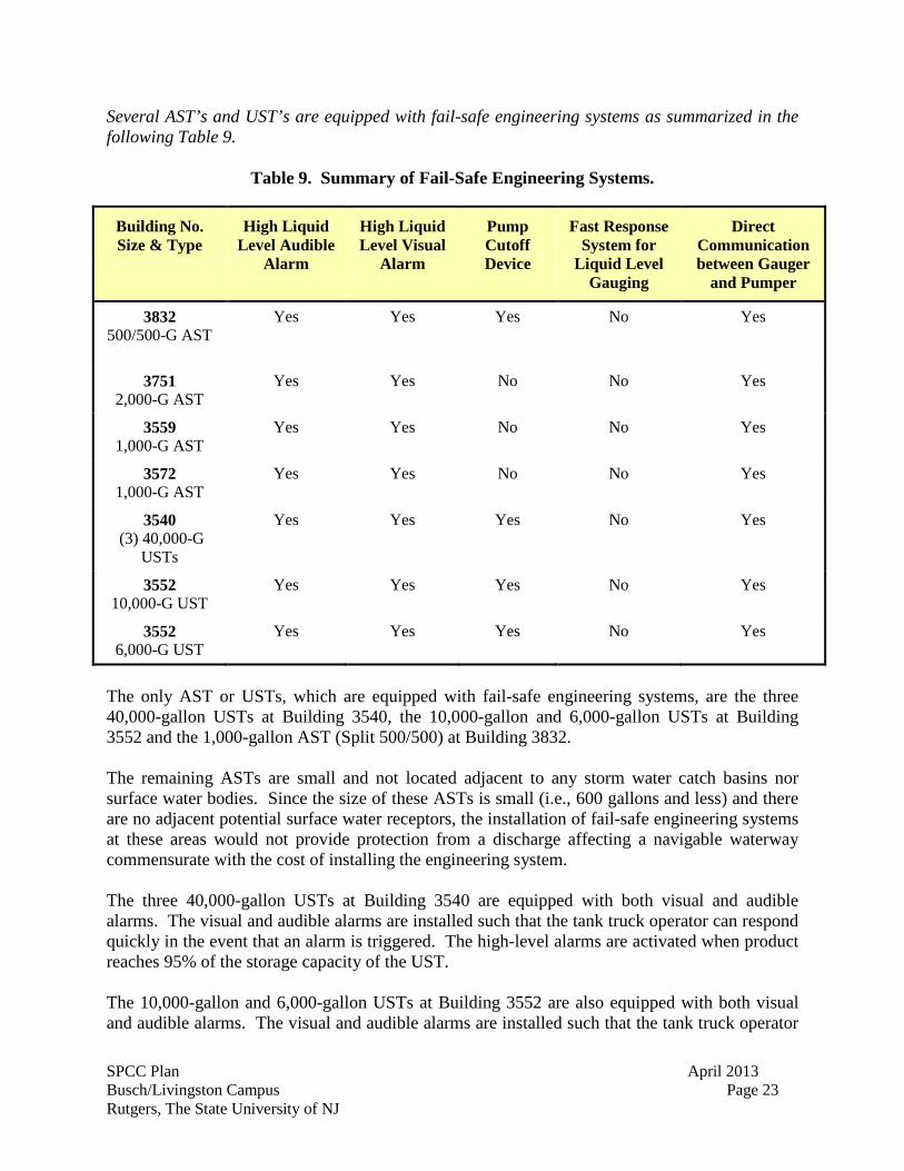
Several AST’s and UST’s are equipped with fail-safe engineering systems as summarized in the following Table 9.
Table 9. Summary of Fail-Safe Engineering Systems.
Building No. Size & Type
High Liquid Level Audible
Alarm
High Liquid Level Visual
Alarm
Pump Cutoff Device
Fast Response System for
Liquid Level Gauging
Direct Communication between Gauger
and Pumper
3832 500/500-G AST
Yes Yes Yes No Yes
3751 2,000-G AST
Yes Yes No No Yes
3559 1,000-G AST
Yes Yes No No Yes
3572 1,000-G AST
Yes Yes No No Yes
3540 (3) 40,000-G
USTs
Yes Yes Yes No Yes
3552 10,000-G UST
Yes Yes Yes No Yes
3552 6,000-G UST
Yes Yes Yes No Yes
The only AST or USTs, which are equipped with fail-safe engineering systems, are the three 40,000-gallon USTs at Building 3540, the 10,000-gallon and 6,000-gallon USTs at Building 3552 and the 1,000-gallon AST (Split 500/500) at Building 3832. The remaining ASTs are small and not located adjacent to any storm water catch basins nor surface water bodies. Since the size of these ASTs is small (i.e., 600 gallons and less) and there are no adjacent potential surface water receptors, the installation of fail-safe engineering systems at these areas would not provide protection from a discharge affecting a navigable waterway commensurate with the cost of installing the engineering system. The three 40,000-gallon USTs at Building 3540 are equipped with both visual and audible alarms. The visual and audible alarms are installed such that the tank truck operator can respond quickly in the event that an alarm is triggered. The high-level alarms are activated when product reaches 95% of the storage capacity of the UST. The 10,000-gallon and 6,000-gallon USTs at Building 3552 are also equipped with both visual and audible alarms. The visual and audible alarms are installed such that the tank truck operator
SPCC Plan April 2013 Busch/Livingston Campus Page 24 Rutgers, The State University of NJ
can respond quickly in the event that an alarm is triggered. The high-level alarms are activated when product reaches 95% of the storage capacity of the UST. The 1,000-gallon AST (Split 500/500) at Building 3832 is equipped with an audible alarm. The audible alarm is installed such that the tank truck operator can respond quickly in the event the alarm is triggered. The high-level alarm is activated when product reaches 95% of the storage capacity of the UST. 6.3.9. Observation of disposal facilities for effluent discharge
112.8(c)(9) Observe effluent treatment facilities frequently enough to detect possible system upsets that could cause a discharge as described in paragraph 112.1(b).
This section is not applicable to the facility since there are no disposal facilities. 6.3.10. Visible oil leak corrections from tank seams and gaskets
112.8(c)(10) Promptly correct visible oil leaks which result in a loss of oil from the container, including but not limited to seams, gaskets, piping, pumps, valves, and bolts. You must promptly remove any accumulations of oil in diked areas.
Visible oil leaks are reported to the Director of Facility Maintenance Services (see Section 2). Subsequent to reporting, a work order is written and the tank is repaired prior to being reused. 6.3.11. Appropriate position of mobile or portable oil storage tanks
112.8(c)(11) Position or locate mobile or portable oil storage containers to prevent a discharge as describe in paragraph 112.1(b). You must furnish secondary means of containment, such as dikes or catchment basins, sufficient to contain the capacity of the largest single compartment or container with sufficient freeboard to contain precipitation.
In addition, when a portable storage tank is used (see Section 3.2), it is positioned to (a) prevent any spilled oil from reaching navigable waters and (b) protect the tank from periodic flooding or washout. A secondary means of containment is provided for the largest single compartment or tank. The type of secondary containment is based on the area where the portable storage tank is positioned. 6.4. Bulk Storage Piping
6.4.1. Underground Piping
112.8(d)(1) Provide buried piping that is installed after August 16, 2002 with a protective wrapping and coating. You must also cathodically protect such buried piping installations or otherwise satisfy the corrosion protection standards for piping in part 280 of this chapter or a state program approved under part 281 of this chapter. If a
SPCC Plan April 2013 Busch/Livingston Campus Page 25 Rutgers, The State University of NJ
section of buried line is exposed for any reason, it should be carefully inspect it for deterioration. If you find corrosion damage, you must undertake, additional examination and corrective action as indicated by the magnitude of the damage.
All underground piping associated with USTs is constructed in accordance with N.J.A.C. 7:14-4.2. Underground piping at the three 40,000-gallon USTs at Building 3540 and the 10,000-gallon and 6,000-gallon USTs at Building 3552 is double-walled, fiberglass-coated outer steel and interstitial monitoring and alarm systems. 6.4.2. Provisions for piping not in service
112.8(d)(2) Cap or blank flange the terminal connection at the transfer point and mark it as to origin when piping is not in service for an extended period of time.
When aboveground piping at the ASTs is not in use, the terminal connection at the transfer point, where applicable, is capped. All aboveground piping is labeled with product content, origin and direction of flow. 6.4.3. Aboveground Piping Support
112.8(d)(3) properly design pipe supports to minimize abrasion and corrosion and allow for expansion and contraction.
There is no aboveground piping at ASTs at Buildings 3500, 3522, 3555, 3559, 3752, 3757, 3862, 3881, 3832, 3751, 3540, 3863, 3877, 3892, 4100, 4117, 4136, 4138, 4177, 4178, 4179, 4180, tunnel, and pump house. The aboveground piping at the ASTs at Buildings 3751, 3831, 3826, 3832 (275-gallon) 4101, and the tunnel does not require supports external to the building, since all the tanks are located immediately adjacent to the building. The external aboveground piping at Buildings 3558, 3559, 3573, 3757, 3826, 3831, 3881, 3883, 3558, 3903, 4140, 4143, 4145, 4152, 4146, and 4156 is adequately supported. 6.4.4. Aboveground valve and pipeline examination
112.8(d)(4) Regularly inspect all aboveground valves, piping and appurtenances. During the inspection you must assess the general conditions of items, such as flange joints, expansion joints, valve glands and bodies, catch pans, pipeline supports, locking of valves, and metal surfaces. You must conduct integrity and leak testing of buried metal piping at the time of installation, construction, relocation, or replacement.
Aboveground piping and valves are inspected at the time facility inspections are conducted on a monthly basis.
SPCC Plan April 2013 Busch/Livingston Campus Page 26 Rutgers, The State University of NJ
6.4.5. Aboveground piping protection from vehicular traffic
112.8(b)(5) Warn all vehicles entering the facility to be sure that no vehicle will endanger aboveground piping or other oil transfer operations.
All aboveground piping is protected from vehicular traffic. The aboveground piping at Buildings 3558, 3559, 3573, 3757, 3826, 3831, 3881, 3883, 3903, 4101, 4140, 4143, 4145, 4152, 4146, and 4156 is located between the AST and the building. Piping at the 1,000-gallon (split 500 gallons unleaded gasoline and 500 gallons diesel) AST at Building 3832 is protected from vehicular traffic since it is located along a side of the secondary containment vault inaccessible by vehicle and has concrete bollards. 6.5. Facility Truck Unloading
6.5.1. Unloading procedures meet DOT regulations
Rutgers requires all drivers to comply with DOT regulations in 49 CFR part 177 and a facility standard operating procedure (see Attachment D). 6.5.2. Secondary containment for tank trucks
112.7(h)(1) Facility tank car and tank truck loading/unloading rack (excluding offshore facilities). Where loading/unloading area drainage does not flow into a catchment basin or treatment facility designed to handle discharges, use a quick drainage system for tank truck loading and unloading areas. You must design a containment system to hold at least the maximum capacity of any single compartment of a tank car or tank truck loaded or unloaded at the facility.
All tank truck unloading areas associated with oil storage areas are undiked. However, the only areas where there is a reasonable potential for a discharge to reach a storm water catch basin are at Buildings 3540 and 3552. In other areas, a discharge from an AST or during truck unloading would either flow to the ground or laterally spread across paved areas. Under this scenario, the discharge could be cleaned prior to affecting any navigable waterway or any route to a navigable waterway. To minimize the potential for a discharge to the storm water catch basins, prevention measures are utilized at these locations during unloading. At areas where there is a catch basin, a diversion boom is either placed around the catch basin and/or around the tanker truck prior to unloading. At Building 3540 and 3552, a diversion boom is placed around the tank truck. The placement of the diversion boom is designed to contain a discharge within the asphalt pavement. 6.5.3. Warning or barrier system for vehicles
112.7(h)(2) Provide an interlocked warning light or physical barrier system, warning signs, wheel chocks, or vehicle break interlock system in loading/unloading areas to
SPCC Plan April 2013 Busch/Livingston Campus Page 27 Rutgers, The State University of NJ
prevent vehicles from departing before complete disconnection of flexible or fixed transfer lines.
Warning signs are posted in all the unloading areas for the ASTs and UST locations to prevent vehicular departure before disconnecting flexible or fixed transfer lines. 6.5.4. Vehicles examined for lowermost drainage outlets before leaving
112.7(h)(3) Prior to filling and departure of any tank car or tank truck closely inspect for discharges the lowermost drain and all outlets of such vehicles, if necessary, ensure that they are tightened, adjusted, or replaced to prevent liquid discharge while in transit.
Warning signs are posted in all the loading areas for the ASTs and the USTs to remind drivers to examine drain outlets prior to departure. 6.6. Inspections and Recordkeeping
112.7(e) Conduct inspections and test required of this part in accordance with written procedures that you or the certifying engineer develop for the facility. You must keep these written procedures and a record of the inspections and tests, signed by the appropriate supervisor or inspector, with the SPCC Plan for a period of three years. Records of inspections and tests kept under usual and customary business practices will suffice for purposes of this paragraph
Facility inspection procedures:
Formal facility inspections are conducted monthly and records of these inspections are documented and signed by the inspector. During the monthly inspections, all unloading areas, containment structures, valves, pipelines, and other equipment are inspected. The checklist used for these inspections can be found in Attachment B.
Length of time records kept:
Inspection, training, and tank integrity testing records are retained for at least three years. 6.7. Site Security
6.7.1. Fencing
112.7(g)(1) Fully fence each facility handling, processing, and storing oil and lock and/or guard entrance gates the facility is not in production or is unattended.
Fencing is not provided around all of the oil storage areas since the facility is a college and access to the areas in which the ASTs and USTs are located cannot be restricted. Fencing is provided around the ASTs at Buildings 3522, 3831, 3826, 3559, 3832 (only 500/500-gallon split AST), 3903, 4101, 4100, 4138, 4177, 4178, 4179 and 4180.
SPCC Plan April 2013 Busch/Livingston Campus Page 28 Rutgers, The State University of NJ
Despite the lack of fencing at other ASTs (275-gallon at Buildings 3751 and 3832), there is a low probability that a discharge could occur as a result of unauthorized access. Additionally, there is a low probability that a discharge could occur as a result of unauthorized access to a UST area; therefore, fencing is not provided in UST areas. 6.7.2. Flow valves locked
112.7(g)(2) Security. Ensure the master flow and drain valves and any other valves permitting direct outward flow of the container’s contents to the surface have adequate securely measures so that they remain in the closed position when in non-operating or nonstandby status.
The only ASTs where there is piping, which could result in the tank contents flowing to the ground surface, are at the ASTs at Buildings 4100. The piping for this AST is connected to a fuel dispenser which is protected by a lock. 6.7.3. Starter controls locked
112.7(g)(3) Lock the starter control on each oil pump in the ‘off’ position and locate it at a site accessible only to authorized personnel when the pumps are in a non-operating or non-standby status.
Starter controls for pumps associated with boilers and the emergency generators are located in areas accessible only to authorized Rutgers personnel. Starter controls for fuel dispensers which service the AST at Buildings 3832 and 4100 are protected by locks. 6.7.4. Fill piping connections securely capped
112.7(g)(4) Securely cap or blank flange the loading/unloading connections of oil pipelines or facility piping when not in service or standby service.
All fill piping connections are securely capped when they are not in use and blank-flanged when they are in standby service for an extended time. 6.7.5. Lighting adequate to detect spills
112.7(g)(5) Provide facility lighting commensurate with the type and location of the facility that will assist in the: (i) Discovery of discharges occurring during hours of darkness, both by operating personnel, if present, and by nonoperating personnel (the general public, local police, etc.) and (ii) Prevention of spills occurring through acts of vandalism.
Lights illuminate the oil storage areas. Lights are automatically turned on. Lighting is adequate to detect spills during nighttime hours and deter vandalism.
SPCC Plan April 2013 Busch/Livingston Campus Page 29 Rutgers, The State University of NJ
6.8. Personnel Training and Spill Prevention Procedures
6.8.1. Personnel instructions
112.7(f)(1) Personnel, training and discharge prevention procedures. At a minimum, train your oil handling personnel in the operation and maintenance of equipment to prevent the discharges; discharge procedure protocols; applicable pollution control laws, rules and regulations; general facility operations; and, the contents of the SPCC Plan.
Any personnel responsible for implementing the provisions of this SPCC Plan are required to have spill prevention training that includes a complete review of Rutgers' SPCC Plan. Rutgers conducts training to ensure that these personnel are familiar with the SPCC Plan and the measures to be implemented in the event of a discharge. 6.8.2. Designated person accountable for spill prevention
112.7(f)(2) Designate a person at each applicable facility who is accountable for oil spill prevention and who reports to facility management.
The Facility/Utility/Housing Director is the designated person accountable for spill prevention at Rutgers- Busch/Livingston. 6.8.3. Spill prevention briefings
112.7(f)(3) Schedule and conduct discharge prevention briefings for your oil-handling personnel at least once a year to assure adequate understanding of the SPCC Plan for that facility. Such briefings must highlight and describe known discharges in paragraph 112.1(b) or failures, malfunctioning components, and recently developed precautionary measures.
During annual safety briefings, spill prevention is discussed. Any incidents are discussed in these briefings in order to prevent them from recurring. Employee feedback and recommendations are encouraged in spill prevention and operation. 6.9. Spill Control Equipment
Spill control equipment on site includes absorbent pads and booms, granular absorbent, storm drain covers, empty drums, brooms, and shovels. Spill equipment is stored in facility/housing maintenance areas. 6.10. Emergency Contacts
Part 110-Discharge of Oil: 110.10 Notice. Any person in charge of a vessel or of an onshore or offshore facility shall, as soon as he or she has knowledge of any discharge of oil from such vessel or facility in violation of §110.6, immediately notify the National
SPCC Plan April 2013 Busch/Livingston Campus Page 30 Rutgers, The State University of NJ
Response Center (NRC) (800-424-8802; in the Washington, DC metropolitan area, 426-2675). If direct reporting to the NRC is not practicable, reports may be made to the Coast Guard or EPA predesignated On-Scene Coordinator (OSC) for the geographic area where the discharge occurs. All such reports shall be promptly relayed to the NRC. If it is not possible to notify the NRC or the predesignated OCS immediately, reports may be made immediately to the nearest Coast Guard unit, provided that the person in charge of the vessel or onshore or offshore facility notifies the NRC as soon as possible. The reports shall be made in accordance with such procedures as the Secretary of Transportation may prescribe. The procedures for such notice are set forth in U.S. Coast Guard regulations, 33 CFR part 153, subpart B and in the National Oil and Hazardous Substances Pollution Contingency Plan, 40 CFR part 300, subpart E. (Approved by the Office of Management and Budget under the control number 2050-0046).
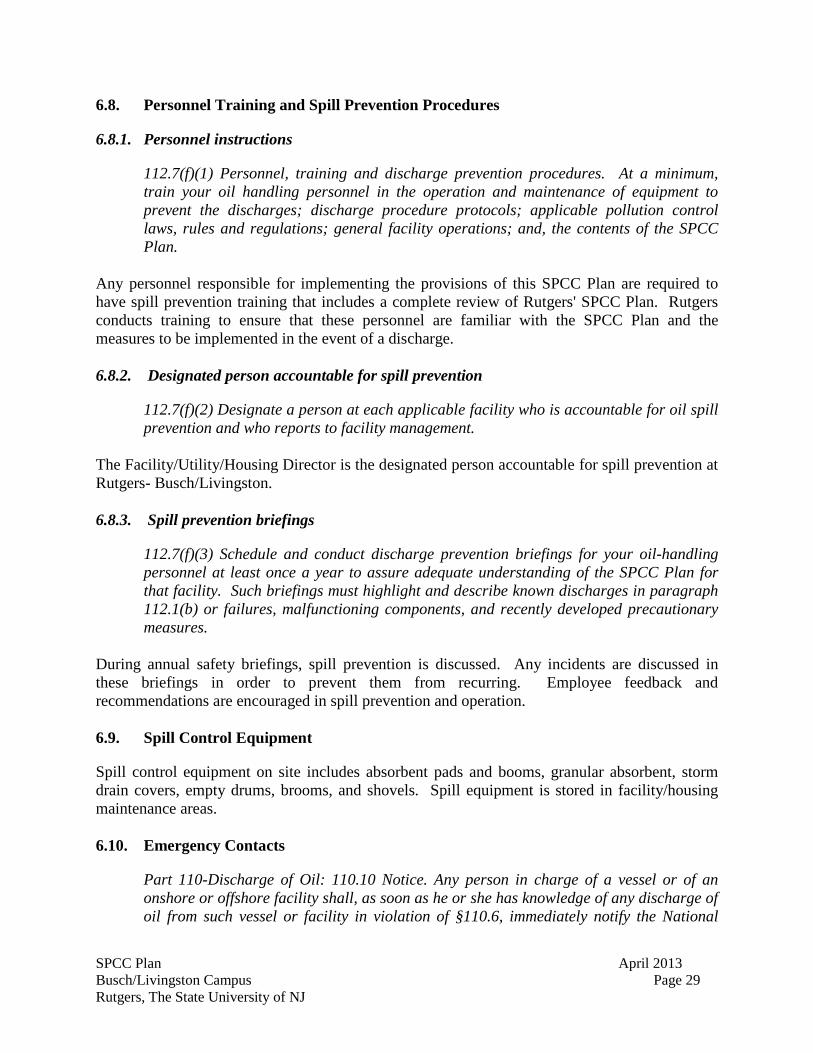
In the event of discharge, the person who is at the scene shall first contact the Rutgers Emergency Coordinator designated below. The Rutgers Police shall then contact REHS and Emergency Personnel, as necessary. Table No. 9 is a list of emergency contacts.
Table 10. Emergency Contacts
Name/Organization Phone Number
Rutgers Police (732) 932-7211 Federal National Response Center (800) 424-8802
NJDEP Spill Hotline (877) WARN DEP
New Brunswick Health Department (732) 745-5021
New Brunswick Fire/Police Department 9-1-1
SPCC Plan April 2013 Busch/Livingston Campus Rutgers, The State University of NJ
ATTACHMENT A Certification of the Applicability of the Substantial Harm Criteria (40 CFR 112.20)
SPCC Plan April 2013 Busch/Livingston Campus Rutgers, The State University of NJ
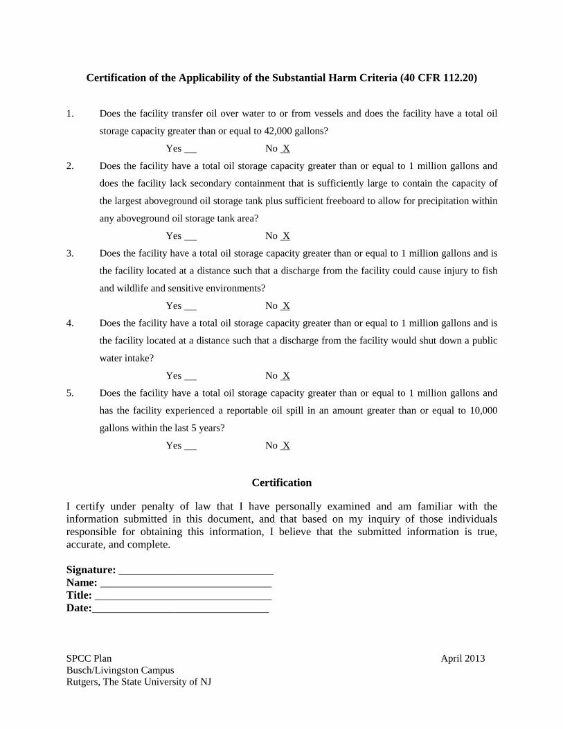
Certification of the Applicability of the Substantial Harm Criteria (40 CFR 112.20)
1. Does the facility transfer oil over water to or from vessels and does the facility have a total oil
storage capacity greater than or equal to 42,000 gallons?
Yes No
2. Does the facility have a total oil storage capacity greater than or equal to 1 million gallons and
does the facility lack secondary containment that is sufficiently large to contain the capacity of
the largest aboveground oil storage tank plus sufficient freeboard to allow for precipitation within
any aboveground oil storage tank area?
X
Yes No
3. Does the facility have a total oil storage capacity greater than or equal to 1 million gallons and is
the facility located at a distance such that a discharge from the facility could cause injury to fish
and wildlife and sensitive environments?
X
Yes No
4. Does the facility have a total oil storage capacity greater than or equal to 1 million gallons and is
the facility located at a distance such that a discharge from the facility would shut down a public
water intake?
X
Yes No
5. Does the facility have a total oil storage capacity greater than or equal to 1 million gallons and
has the facility experienced a reportable oil spill in an amount greater than or equal to 10,000
gallons within the last 5 years?
X
Yes No
X
Certification
I certify under penalty of law that I have personally examined and am familiar with the information submitted in this document, and that based on my inquiry of those individuals responsible for obtaining this information, I believe that the submitted information is true, accurate, and complete. Signature: ____________________________ Name: _______________________________ Title: ________________________________ Date:________________________________
SPCC Plan April 2013 Busch/Livingston Campus Rutgers, The State University of NJ
ATTACHMENT B Monthly Facility Inspection Checklist
SPCC Plan April 2013 Busch/Livingston Campus Rutgers, The State University of NJ
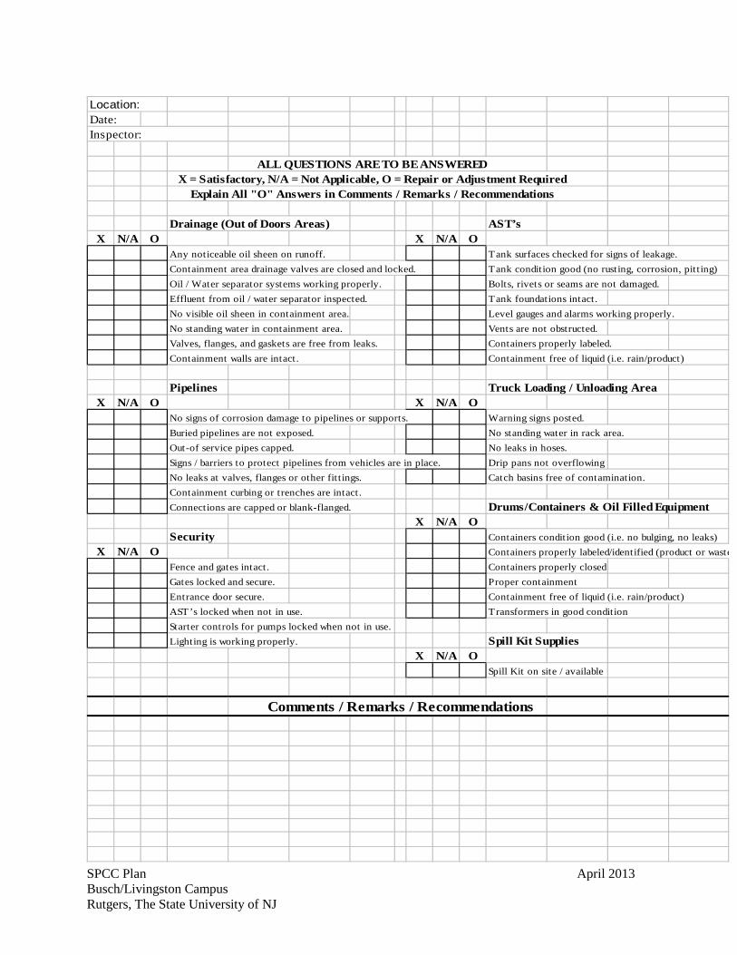
Location: Date: Inspector:
ALL QUESTIONS ARE TO BE ANSWEREDX = Satisfactory, N/A = Not Applicable, O = Repair or Adjustment Required
Explain All "O" Answers in Comments / Remarks / Recommendations
Drainage (Out of Doors Areas) AST’sX N/A O X N/A O
Any noticeable oil sheen on runoff. Tank surfaces checked for signs of leakage.Containment area drainage valves are closed and locked. Tank condition good (no rusting, corrosion, pitt ing)Oil / Water separator systems working properly. Bolts, rivets or seams are not damaged.Effluent from oil / water separator inspected. Tank foundations intact.No visible oil sheen in containment area. Level gauges and alarms working properly.No standing water in containment area. Vents are not obstructed.Valves, flanges, and gaskets are free from leaks. Containers properly labeled.Containment walls are intact. Containment free of liquid (i.e. rain/product)
Pipelines Truck Loading / Unloading AreaX N/A O X N/A O
No signs of corrosion damage to pipelines or supports. Warning signs posted.Buried pipelines are not exposed. No standing water in rack area.Out-of service pipes capped. No leaks in hoses.Signs / barriers to protect pipelines from vehicles are in place. Drip pans not overflowingNo leaks at valves, flanges or other fit t ings. Catch basins free of contamination.Containment curbing or trenches are intact.Connections are capped or blank-flanged. Drums/Containers & Oil Filled Equipment
X N/A OSecurity Containers condition good (i.e. no bulging, no leaks)
X N/A O Containers properly labeled/identified (product or wasteFence and gates intact. Containers properly closedGates locked and secure. Proper containmentEntrance door secure. Containment free of liquid (i.e. rain/product)AST’s locked when not in use. Transformers in good conditionStarter controls for pumps locked when not in use.Lighting is working properly. Spill Kit Supplies
X N/A OSpill Kit on site / available
Comments / Remarks / Recommendations
SPCC Plan April 2013 Busch/Livingston Campus Rutgers, The State University of NJ
ATTACHMENT C Standard Operating Procedure - Tank Truck Unloading
SPCC Plan April 2013 Busch/Livingston Campus Rutgers, The State University of NJ
STANDARD OPERATING PROCEDURE – TANKER TRUCK UNLOADING
This standard operating procedure (SOP) is for the unloading of petroleum products only at Rutgers University. The SOP is intended to be used for unloading from tanker trucks into above ground or underground storage tanks. PRIOR TO UNLOADING
1. Ensure that tanker truck is positioned in approved location for unloading. 2. Make sure that parking brakes on tanker trucks are engaged. Secure the
loading/unloading vehicle prior to transfer operations with physical barriers such as wheel chocks and interlocks, to safeguard against accidental movement and rupture of transfer lines.
3. If applicable to the storage location, verify that containment structures are intact and spill
control equipment is readily available. 4. Inspect condition of all storage tank flanges, joints, connections, and outlets. Tighten,
adjust, or replace as necessary prior to unloading. 5. Properly lock in the closed position all drainage valves in the secondary containment
structure. 6. Closely examine the lowermost drain and all outlets of the tanker truck for leakage or
defects. If necessary, properly tighten, adjust, or replace to prevent liquid leakage while in transit.
7. Establish adequate bonding/grounding of the tanker truck and receiving container before
connecting to the fuel transfer point. 8. Keep hose ends tightly capped while moving hoses into position. 9. Position transfer hoses inside containment structures. 10. Check the pumping circuit and verify the proper alignment of valves. 11. Gauge storage tank to determine volume required. 12. The transfer of Class 3 (flammable liquids) materials, shut off motors of the tank truck
when making and breaking hose connections. If unloading is done without requiring the use of the motor of the tank truck to operate pumps, keep the motor shut off throughout unloading.
During Unloading 1. The driver, operator and/or attendant of a tanker truck should remain in the immediate
area but outside the vehicle during unloading. 2. When unloading, keep the internal and external valves on the receiving tank open.
SPCC Plan April 2013 Busch/Livingston Campus Rutgers, The State University of NJ
3. Make sure that communication is maintained between the pumping and receiving operators at all times.
4. Periodically inspect the condition of the alligator clips, especially the joint between the
bonding wire and the clip, to ensure effective bonding circuits.
5. Monitor all hose couplings during unloading.
6. Monitor the liquid level in the receiving tank during unloading to prevent overflow.
7. Monitor flow meters to determine rate of flow during unloading>
8. Reduce flow rate while topping off the tank to provide sufficient reaction time for pump shutdown without overflow of the receiving tank.
9. Never completely fill the receiving tank; provide a minimum of 1 percent ullage to
prevent leakage due to thermal expansion. SUBSEQUENT TO UNLOADING
1. Make sure all material has been transferred to tank prior to disconnecting any transfer
hoses.
2. Close all tank valves and tanker truck internal, external, and dome-cover valves before disconnecting.
3. Secure all hatches.
4. Disconnect grounding/bonding wires.
5. Prior to vehicle departure, make sure that all connections, fill lines, and
grounding/bonding wires are disconnected.
6. Use a drip pan when breaking a connection.
7. Make sure that the hoses are drained, vented, or blown down, to remove the remaining oil before moving them away from their connections.
8. Cap the end of the hose or other connecting devices before moving them, to prevent
uncontrolled oil leakage.
9. Disconnect, drain, and support out-of-service or standby hoses, to avoid crushing or excessive strain.
10. Cap associated hose risers.
11. Close all hose riser valves not in use.
12. Remove wheel chocks.