status and plans of the wa105 experiment · 6 m prompt uv light de/dx ionization photomultipliers...
TRANSCRIPT

Status and plans of the WA105 experiment
V. Galymov
for WA105 Collaboration
121st Meeting of CERN SPSC
April 2016

Dual-phase TPC prototype at CERN
Characterize the detector with well defined particle beams• Study PID performance• Evaluate e/𝜋0 rejection capabilities• Calibrate energy scale and evaluate resolution for electronic and
hadronic showers• Validate reconstruction tools
Systematics for future neutrino oscillation program • Measure hadron shower development with exceptional granularity
3x3 mm2
Requires:• Pions/protons: reconstruction of secondaries in hadronic interactions,
measurements of hadronic shower development, study compensation and energy resolution
• Electrons: calibrate energy scale and resolution
2

Dual-phase TPC prototype at CERN
Demonstrate technical feasibility for O(10kton) detectors • Large surface charge readout in dual-phase scalable to
O(10kton) scale detectors
• Charge readout with 3mm pitch in two collection views
• Long drift distances
• High voltage to generate drift field
• Production and QA/QC chains for all detector elements
• Validation of installation sequence in view of underground detector assembly
3

WA105 dual-phase LAr TPC
4
E=0.5-1.0 kV/cm
Cathode
LAr volume ~300 ton active
Drift
6 m
Prompt UV light
dE/dx ionization
Photomultipliers
Readout in gas phase:charge is amplified and collected on a 2D anode
Drift coordinate 6 m = 4 mssampling 2.5 MHz (400 ns), 12 bits 10000 samples per drift window
Total event size 148MB Data rate 15GB/s (at 100 Hz trigger) DAQ bandwidth on 20 GB/s scale
Charge Readout Plane (CRP) X and Y charge collection strips3.125 mm pitch, 3 m long 7680 readout channels
3 m
Detector is built from 4 independent 3x3 m2 unitsFor multi-kton detector, simply increase the number of CRPs

5
80cm
Collection Collection
S/N≈100 S/N≈100
View x View y
Double-phase prototypesmeasuring real data events since 6 years with active volumes from 3 to 250 liters
> 15 millions of cosmic events collected in stable conditionsS/N~100 for m.i.p. achieved starting from gain ~15
Dual-phase concept advantages: • 3mm pitch (or less?)• Robust S/N with tunable gain• Only charge collection (no
induction planes)• Can cope with electron
diffusion & charge attachment for long drift
• Insensitive to microphonic noise
Max gain ~200
S/N≈800
Literature:NIM A617 (2010) p188-192NIM A641 (2011) p 48-57JINST 7 (2012) P08026JINST 8 (2013) P04012JINST 9 (2014) P03017JINST 10 (2015) P03017

6
WA105 Technical Design Report:
TDR submitted on 31st March 2014CERN-SPSC-2014-013SPSC-TDR-004(2014)
2015 Annual SPSC progress report 31st March 2015 SPSC-SR-158
WA105 project MOU fully signed, December 2015
History of WA105 / Dual-phase ProtoDUNE
Project started in 2013 (CERN RB approval) following the submission of LBNO Expression of Interest
Collaborators from 10 countriesand 22 institutes
6
Integration in DUNE project as DP-ProtoDUNEDecember 2015; EOI call for ProtoDUNEs, January 2016Positive response (21 institutions submitted EOIs)• Covering all identified DP-ProtoDUNE subsystems• In process of bringing together interested institutions
2016 Annual SPSC progress report, 7th April 2016 CERN-SPSC-2016-017 SPSC-SR-184
DUNE CDR, July 2015: WA105 and Dual-phase 10 kton design
From past SPSC recommendations: “encouraged CERN and the WA105 collaboration to (...) undertake all efforts to be ready with DLAr in the EHN1 extension for first beam before the start of the Long Shutdown 2.”

LArProto: 3x1x1 m3 pilot
7
• 25 ton dual-phase LAr TPC pilot prototype at CERN Bld 182• Charge readout area = 3x1 m2, Drift = 1 m• Significant progress on the pilot in the last year to
construct the detectorStarts taking cosmics in September 2016
Bld 182

LArProto: 3x1x1 m3 pilot
Extremely useful:• Routine procedure for mass production, QA/QC tests, and calibration of LEMs• Cryogenic installation, feedthroughs, thermodynamic condition of the tank,
integration, … • Legal and technical aspects related to cryostat procurement• Validation of production schedule for 6x6x6 m3
• But due to its size• Not a test of very large vessel and field cage structure• No large surface charge readout• No long drift (purity and diffusion)• No very HV generation• No event containment or exposure to hadronic beamNot a demonstrator for a large scale detector and no measurement input for the associated LBL program
8

Progress LArProto
9

Chimneys for accessible cold FE
coated PMTs
slow control flanges
CRP suspensions10
Almost all of the components are now on-siteReady for detector assembly!
Ongoing feedthrough installations in top cap

LEM-anode sandwich
11
RMS0.1 mm
• Clean room infrastructure (ISO-8 class) in Bld. 182
• Full QA chains set up• Now ready for 6x6x6
LAS sandwich metrology
50x50 cm2 LEM / anodes mounted on a frame
GridLAr
Extraction field 2kV/cmGAr
Anode 0V
1 cm
2 mmCollection field 5kV/cm
1mm thick LEM (30-35kV/cm)

Slow control system
12
High accuracy (100 um)and standard (1 mm) level meters
Cryocamera
• Extensive network of sensors to completely characterize behavior of CRP
• System designed in collaboration with CERN EP-DT (G. Miotto, N. Bourgeois, G. Maire, S. Ravat, Y. Rigaut)
• Integrated control of level meters, temperature and pressure sensors, strain gauges, cryocamera
• Based on National Instruments compactRIO with UNICOS supervisor and single LabView interface
• Easily scalable to the DLAr 6x6x6
SCTest rack

CRP cryogenic tests
13
• 50x50 cm2 LEMs have been successfully tested in pure gas argon at 87K
• The fully assembled CRP mechanical structure has been tested twice in open LAr bath
• Photogrammetry and strain gauges to measure deformations
• Test of near final configuration (anodes, LEMs, level meters, cameras, …) done in March 2016
• All instrumentation functioned properly
With help from cryo groupat CERN: J. Bremer, D. Montanari
3x1 CRP in open LAr bath
Mini CRP

High voltage
14
• Minimal required HV on the cathode for DLAr is 300 kV 0.5 kV/cm drift field strength over 6m
• HV feedthrough for LArProto capable to withstand 300kV operation has been designed
• The FT will be tested at CERN with 300kV Heinzinger PS already acquired for WA105
COMSOL simulation of fields around feedthrough

15

WA105 6x6x6 timeline
16
Cryostat ready for detector installation
Jul 2016
Sep 2016
Mar 2017
Apr2017
…
Start of cryostat construction
Cryogenics ready
Final design of detector elements
All CRPs assembledReady for installation
CRPs installed & cabled
Detector fully installed and cabled
Aug2017
Dec2017
…Jan
2018Feb2018
Mar2018
Apr2018
TCO & cryostat sealed
Beam data
Start cryogenic operation & detector commissioning
Ready to start beam data taking
WA105 timeline is fully compatible with EHN1 general scheduleThe critical path is defined by availability of infrastructure (clean room in Bld 185, cryostat, cryogenics) provided by Neutrino Platform
EHN1 infrastructure milestones
First cosmics
In a year from now
Jan 2017
Clean room for CRP assembly Bld 185
… ……
Start CRP assembly

WA105 DLAr in EHN1
Target for H2 secondary beam inside concrete shielding
Beam aimed at the center of the TPC
• The design of the beamline is almost complete• First results of flux simulations from CERN beamline group included in the
evaluation of the beam time request
• Efforts to be placed on design of beam instrumentation• Particle ID system for 𝜋/p/K over all beam momentum range
• Magnetic spectrometer to reduce momentum bite from 5% to ~1%17

Completed definition of all detector interfaces to cryostat infrastructure
EHN1 Cryogenics: Design closure in April 2016 Cryo specification meeting 14/04/16 Contract to be assigned by end of June 2016 Installation summer 2017
Schedule EHN1: Construction of steel structure:July-September 2016 Assembly of cryogenic insulation: October 2016-April 2017 Detector assembly inside the cryostat:
April-November 2017
Interface to CERN infrastructure
18

Modular CRP
WA105: 4 CRPs DUNE 10kt: 80 CRPs
• CRP is composed of 4 3x3 m2 readout units built from 50x50 cm2 LEM and anodes
• Each unit has its own suspension system• Charge is collected on 3m “strips”• Identical structure is envisioned for DUNE 10kt
19

Status of CRP• CRP design is being finalized
• Extrapolation based on experience from 3x1 CRP design• Extraction grid with 3m long wires
• Photogrammetry measurements and slow control data from cold bath tests
• Minimize spacing between adjacent CRP modules – presently gap of 10mm (warm)
• Account for thermal contraction between different elements
20
Decoupled fixation system
Constrain inter-module distance between CRPs <10mm
LEM
Anode
Extraction wire grid submerged in LAr
Cold tests of decoupling system
3x3 CRP 3x3 CRP

Light readoutTPB coated plate
8” PMT
• Scintillation light is detected with a grid of 36 8” Hamamatsu (RD5912mod2) PMTs
• The PMTs are attached SS base plates affixed to cryostat membrane in flat regions between corrugation grooves
• Support weight is designed to cancel out PMT buoyancy
no net strain on the membrane
• Signal/HV splitter circuit has been developed to allow for a single coaxial cable connection per PMT
• Minimizes # of cables and feedthroughs
• System for PMT characterization at room and cryogenic temperature has been built (up-to 4 PMTs could be tested simultaneously)
• Gain – voltage calibration
• Dark current rates
• PMT procurement from Jun. 2016 – Sep. 2016
• Design of calibration system for DLAr underway
21
Field cage & cathode
22
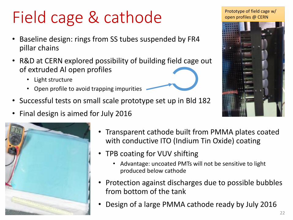
• Baseline design: rings from SS tubes suspended by FR4 pillar chains
• R&D at CERN explored possibility of building field cage out of extruded Al open profiles
• Light structure
• Open profile to avoid trapping impurities
• Successful tests on small scale prototype set up in Bld 182
• Final design is aimed for July 2016
• Transparent cathode built from PMMA plates coated with conductive ITO (Indium Tin Oxide) coating
• TPB coating for VUV shifting • Advantage: uncoated PMTs will not be sensitive to light
produced below cathode
• Protection against discharges due to possible bubbles from bottom of the tank
• Design of a large PMMA cathode ready by July 2016
Prototype of field cage w/ open profiles @ CERN

Detector installation in EHN1
23
TCO
4.4
m
1.2m
• First feedthroughs are installed
• The material for detector installation is brought to a clean room buffer and then TCO into the cryostat
• CRPs will be pre-assembled at CERN and then packed in a protective case and then brought in vertically via TCO
Installation sequence same as for 10kt DUNE
• For CRP assembly at CERN a clean room in Bld 185 is requested Assembly of first CRP to start Jan 2017
TCO = Temporary Construction Opening

CRP 3X3 m²
• First CRP assembled and in
position
24
A sequence of frames showing a cut view inside the cryostat will illustrate the assembly procedure

CRP 3X3 m²
• CRP lifted
25

CRP 3X3 m²
• Same Procedure for the other
CRPs
26

CRP 3X3 m²
• All CRPs fixed on nominal
Position
27

Field Cage
• First Field Shaper Installed
28

Field Cage
• Drift Cage is lifted as the field
shaper are istalled
29

Field Cage
• Last field shapers not yet
mounted
30

• Part of the temporary floor is
removed
Cathode and PMTs
31

• Cathode structure assembled
on the floor
Cathode and PMTs
32

• PMTs Installation at the
structure
Cathode and PMTs
33

• PMMA coated Plates installed
at the Cathode
Cathode and PMTs
34

Cathode and PMTs
• Installation of the last field
shapers
35

Cathode and PMTs
• Cathode connected to the
Drift Cage and Lifted
36

Removal of Temporary Assembly Floor
• Temporary Assembly floor
removed
37

Closure of the TCO
• Membrane and TCO closed
38
Cold front-end electronics
39
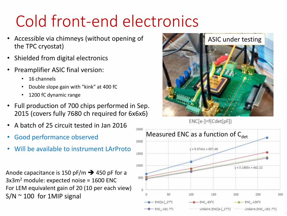
ASIC under testing
Anode capacitance is 150 pF/m 450 pF for a 3x3m2 module: expected noise = 1600 ENCFor LEM equivalent gain of 20 (10 per each view)
S/N ~ 100 for 1MIP signal
Measured ENC as a function of Cdet
• Accessible via chimneys (without opening of the TPC cryostat)
• Shielded from digital electronics
• Preamplifier ASIC final version: • 16 channels
• Double slope gain with “kink” at 400 fC
• 1200 fC dynamic range
• Full production of 700 chips performed in Sep. 2015 (covers fully 7680 ch required for 6x6x6)
• A batch of 25 circuit tested in Jan 2016
• Good performance observed
• Will be available to instrument LArProto

Digital electronics and DAQ scheme
40
Digital electronics for charge readout• microTCA standard• 10 cards per crate• 64 ch per card• 12bit resolution• 2.5 MHz rate
Digital electronics for light readout• microTCA standard• 4 cards in a crate• 9 ch per card• 14bit resolution• 2.5 (max 65) MHz

Charge readout digital electronics status
• The time and trigger distribution based on White Rabbit (WR) standard has been defined
• WR slave cards have been adapted to microTCA format and configured
• All necessary components (ADC, FPGA, memory) evaluated with BittwaremicroTCA development kit
• Final quantities purchased for DLAr
• Routing and PCB layout is being completed• A pre-production batch of 10 cards will be tested in May 2016
• Development of the OpenCL software for the back-end Bittware cards on the event building stations is on-going
• In June 2016 a subset of analog and digital electronics produced for DLArwill be installed in LArProto to provide DAQ for the operation in Sep. 2016
41

Light readout electronics
42
• Integrated into overall WA105 DAQ schemes for the charge readout • Timing and trigger distribution via WR
• Front-end cards are based on microTCA standard
• Digitized data is written in cyclic memory buffers
• On beam trigger, ±4ms is written out with 400ns time granularity to reconstruct T0 of cosmic ray tracks that overlap with the beam event
• Outside of beam trigger, self-triggering mode using PARISROC ASIC dedicated light signal studies
• The electronics design is being finalized for the DLAr deployment
Mezzanine card with PARISROC ASIC

Overview of DAQ & online storage/computing system
43
Data is buffered in 1PB local storage system w/ internal 20 GB/s bandwidth1PB buffer allows running for several days without moving data to CERN storage
384 core cluster for online analysis:• Detector performance checks• Data quality checks• Data preparation for archiving
Data is archived at CERN CASTOR & duplicated to
FNAL

Online processing tasks
• Complete event building by connecting data streams the two back-end boards
• Combine charge and light readout for fast reconstruction and disentangling of cosmic ray track segments
• Skim cosmic ray sample for useful calibration tracks
• Online data quality checks
• Data filtering and formatting for archiving
• Study online data processing and filtering requirements for future 10kt detector
• A scaled version of storage/online computing system is being setup for LArProto with the help of CERN IT
• Optimize the storage/analysis/network hardware and software for final system in EHN1
• Test data transfer and archiving to CERN EOS
44

Calibration data in DLAr
45X coordinate
Tim
e co
ord
inat
e
Example of overlapping cosmics in WA105 TPC in one of the views with each sub-panel corresponding to a 3x3 m2 CRP module
• Readout window is 4ms
• Expected muons from cosmic ~100 in 8ms time window
• Could see fragments of cosmics arriving both before (“closer” to anode) and after (“closer” to cathode) beam trigger
Selected sub-sample of these are data for calibration
• LAr purity analysis
• Gain measurement
• Field non-uniformity effects (track distortions)

Software developmentsTwo parallel directions are pursued
• Implementation of DLAr within LArSoft framework • Profit of the reconstruction tools developed by world-wide community for
analysis of beam data
• WA105 software for simulation and online analysis based on QSCAN• Fast and light-weight, hardware oriented software environment• Simulation:
• Charge quenching effects
• Electron lifetime attenuation
• Diffusion effects
• Response of electronics
• Many recent developments:• Cosmic ray background overlay on the beam events
• Modelling electric field non-uniformities due to space-charge effects
• Light simulation from both LAr and GAr (electroluminescence)
• Simulation tools to meet immediate WA105 needs are in place• Development of light-weight reconstruction tools for DLAr online analysis
• Reconstruction of cosmic ray tracks for fast feedback on the detector operation & data quality
• QSCAN software ready for use in 3x1x1 analysis 46

Benchmarking simulation• Develop automatic procedures to generate sets of benchmark
distribution• Quickly validation new releases
• Analysis tools which will be also part of online monitoring tasks
• Time profiling of reconstruction algorithms for online monitoring
From muon tracks at different detector depths
𝑞 = 𝑞0𝑒− 𝑡𝑑𝑟𝑖𝑓𝑡 𝜏𝑒
From fit:𝑞0 = 35.4 fC𝜏𝑒 = 3.01 ms
Example: electron lifetime (LAr purity) analysis
47

Overall beam particle rates
• Maximum particle rate to avoid too many particle overlaps in TPC:
𝑅 = 100 HzAssume this could be achieved for any momentum setting of the beamline
• For SPS spill of 4.8 s and super-cycle of 2 spills / 50 s the number of particles expected to be delivered to the detector per super-cycle
2 × 4.8 𝑠 × 100 𝐻𝑧 = ~1000 particles / super-cycle
• Assuming 50% running efficiency:
~829k per day
48

Beamline simulation
49
• Simulation of beam optics propagating particles from the target to the detector has been set up with G4Beamline toolkit
• Detailed breakdown of particles rates obtained for different species allows to estimate required running time
Thanks toLau Gatignon (CERN)Nikolaos Charitonidis (CERN)
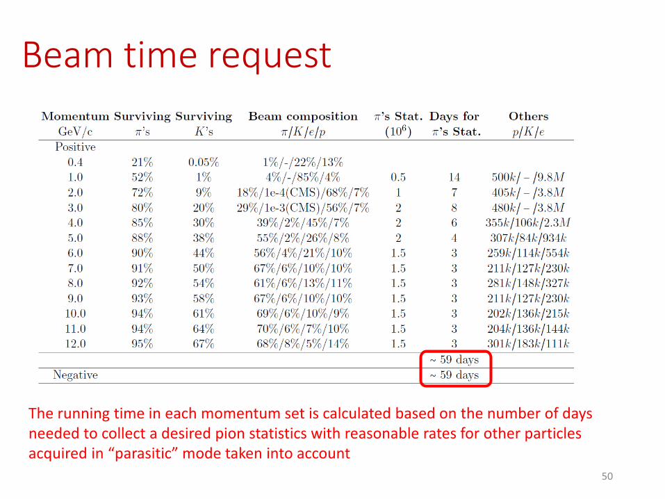
Beam time request
The running time in each momentum set is calculated based on the number of days needed to collect a desired pion statistics with reasonable rates for other particles acquired in “parasitic” mode taken into account
50

Muon halo from H2 secondary line
51
H2 extrapolation to the WA105
cryostat
Red outline of the WA105 active volume
Muons along H2 direction
Without dedicated muon shielding would get ~2kHz rate in TPC from muon halo
Need to reduce as much as possible with upstream magnetized shielding

ConclusionsSignificant progress has been made last year
On schedule for LArProt (3x1x1) in Fall 2016 and DLAr (6x6x6) operation before LHC LS2
Anticipated overall funding covers adequately construction of 3x1x1 and 6x6x6m3
detectors
Significant presence at CERN presently focused at 3x1x1m3 assembly and preparation for operation in September 2016
Entered in the production phase of 6x6x6 DLAr
Request items:
• Mitigation of beam muon halo background
• Clean room for CRP assembly at CERN Bld 185
Overall DLAr detector schedule has been fully integrated with EHN1 schedule
The critical path is set by the availability of the infrastructure from Neutrino Platform
Beam data critical to characterize the performance of the detector and provide physics inputs for future neutrino program
Construction and operation of the 6x6x6m3 prototype will demonstrate our readiness to build a 10kton DUNE FD
52

53
Thank you for your attention

Extra
54

Summary of milestones
55
LArProto 3x1x1 Building 182:
• February 2016: start detector installation (arrival at CERN of
the Top Cap build by Gabadi)
• June 2016: weld top cap and seal cryostat• July 2016: perform test in gas Ar• August 2016: start cryogenic operation (cooldown+filling)
September 2016: start cosmic ray data taking
DLAr 6x6x6 in the NA EHN1:
• September 2016: start cryostat construction• April 2017: start detector installation• December 2017: seal TCO & cryostat• January 2018: start cryogenic operation (cooldown+filling)
April 2018: be ready to collect beam data

56

57

58

59
FTs Installation
Manhole
(Later Installed)
Slow Control FTs
Signal Fts
High Voltage Ft
(Later Installed)
Drift Cage Suspension FT
CRP Suspension Fts
TCO

Temporary Construction Floor
• Cryostat is used as a clean Room
• Field Cage, CRP are installed inside
• Temporary construction floor is needed to
protect the bottom membrane

Field CageField Shapers
Cathode Structure
• Field Cage and Cathode structure is made of
relatively small part (mainly pipes ) that will be
assembled inside the Cryostat
• Assembly procedure was already studied with
an external Engineering Company
(Technodyne for Laguna LBNO study)
Assembly Parts
of a field Shaper
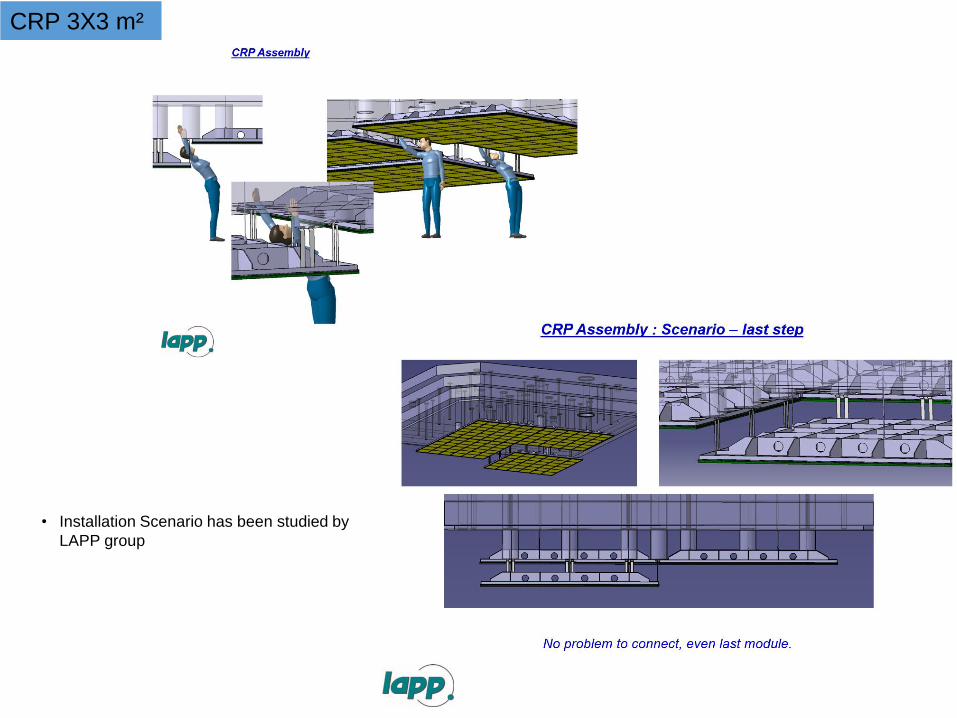
CRP 3X3 m²
• Installation Scenario has been studied by
LAPP group

63
Energy depositions seen at the single wire level for a 1 GeV electron simulated shower(3.125 mm pitch)
m.i.p peak
Electrons from brem. g
m.i.p peak
Electrons from brem. g
Many tiny depositions at the single wire level from brem. photons which contribute to the energy reconstruction
Importance of operating at low energy thresholds < 100 keV Do not consider only average value of m.i.p. peak for S/N but also under-fluctuations in Landau width
A 10-20 MeV electron from a SNB event will brem. and be split in little per-wire depositionsFor SNB is also very important to detect de-excitation gammas of 40K*(40Cl*) for neutrino(anti) tagging Also pointing to relevance of reconstructing low energy depositions for SNB
Charge (fC) Energy (MeV)

64
LEM gain 25 LEM gain 50 LEM gain 100
Distance (m) S/N Thresh. (keV) S/N Thresh. (keV) S/N Thresh. (keV)
6 51 38 103 19 207 9
12 15 133 30 66 59 33
Effect of tunable LEM gain (20-100) on S/N and 3s noise threshold at 6m and 12m distance and for different purity levelsDrift field 0.5 kV/cm, 1300 e- ENC, minimal purity requirement 3 ms (same as for SP)
LEM gain 25 LEM gain 50 LEM gain 100
Distance (m) S/N Thresh. (keV) S/N Thresh. (keV) S/N Thresh. (keV)
6 85 23 170 12 340 6
12 40 49 80 24 161 12
LEM gain 25 LEM gain 50 LEM gain 100
Distance (m) S/N Thresh. (keV) S/N Thresh. (keV) S/N Thresh. (keV)
6 132 15 264 7 528 4
12 96 20 193 10 386 5
3 ms
5 ms
12 ms

Cryostat dimensions
65

Cryogenic system specifications
66
Operating pressure between 950 and 1100 mbarLocal heat input 5 W/m2

67

68
Synergies with single-phase protoDUNE:
• Beam monitoring detectors – joint Working Group.• Beam window/Beam plug – common development through DUNE FD Working Group• Field cage – common development through DUNE Far Detector Working Group• High Voltage – common development through DUNE Far Detector Working Group• Slow Control/Detector Monitoring – joint Working Group• DAQ with areas of common interest such as DAQ software, Run Control software, data formatting
software, and potentially timing distribution hardware• Online Computing focusing on online computing farm, online disk storage, online monitoring, and
data transmission to Tier 0 – joint Working Group• Offline Computing - joint effort through DUNE Software & Computing Working Group• Cosmic triggering - joint Working Group
EOI call within DUNE (January 2016):
New institutes have expressed their interest to work on WA105:FNAL (Computing and Neutrino Divisions), Czech Republic Institutes, University of Texas Arlington, National Centre for Nuclear Research, Kyiv National University, University of Wisconsin, Maryland, Argonne National Laboratory and DUNE-UK.
The expressions of interest included input for construction, commissioning, operation as well as intellectual contributions to WA105.

WA105 cold electronics
69
To increase dynamic range of the front-end electronics up-to 1200 fC the cryogenic amplifier have a double-slope feature:• High gain up-to 400 fC (~13 mip with LEM gain of 10 per collection view)• Smaller slope for high energy depositions
pC
VKink at 400 fC~13 mip with LEM effective gain = 20
~log regime up to 1200 fC
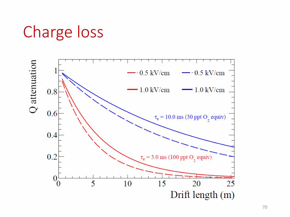
Charge loss
70