status of the tracker outer barrel j. incandela university of california santa barbara for the tob...
Post on 20-Dec-2015
216 views
TRANSCRIPT
Status of the Tracker Outer Barrel
J. Incandela
University of California Santa Barbara
for the TOB Group
Tracker General Meeting December 7, 2005 Slides courtesy of: A. Affolder, P. Bhat, C. Campagnari, Y. Gotra, A. Onnela,
A. Satpathy, L. Shabalina, L. Spiegel, D. White, and others…

Tra
cker
Ou
ter
Bar
rel-
Dec
emb
er 7
, 200
5 –
Tra
cker
Gen
eral
Mee
tin
g s
lide
2
US Module Assembly
Past Week Cumulative
A B C A B C % A or B
L12pu 0 0 0 213 7 2 99.0%
L12pd 0 0 0 285 6 5 98.3%
L12su 0 0 0 201 19 14 94.0%
L12sd 23 1 0 169 20 3 98.4%
L34p 49 1 1 1072 35 8 99.3%
L56p 0 0 0 1486 42 16 99.0%
R5N 16 2 0 220 8 1 99.5%
R5S 0 0 0 237 8 5 97.9%
R6 12 0 0 309 13 1 99.7%
R7 26 0 0 230 17 2 99.1%
Total 126 4 1 4425 175 57 98.8%• Current inventory of components sufficient for > 5 weeks production
• 1.3% C grade modules are mostly very near to spec. (~40/49 will be reclassified for use in rods)

Tra
cker
Ou
ter
Bar
rel-
Dec
emb
er 7
, 200
5 –
Tra
cker
Gen
eral
Mee
tin
g s
lide
3
US Hybrid Testing Status
Weekly CumulativePass Fail Pass Fail % Pass
L12su 0 0 323 1 99.69%L12sd 0 0 294 1 99.66%L12pd 1 -1 352 2 99.44%L34p+L12pu 98 -3 1953 25 98.74%L56p 6 -4 1804 26 98.58%R2N 0 0 189 5 97.42%R2S 7 0 171 6 96.61%R5N 45 -1 554 13 97.71%R5S 65 3 527 12 97.77%R6 0 0 543 10 98.19%R7 1 0 266 2 99.25%Total 223 -6 6976 103 98.54%

Tra
cker
Ou
ter
Bar
rel-
Dec
emb
er 7
, 200
5 –
Tra
cker
Gen
eral
Mee
tin
g s
lide
4
US ARCS Testing Status
Past Week CumulativeA B F A B F % A or B
L12pu 4 0 0 224 0 2 99.12%L12pd 0 0 0 296 0 1 99.66%L12su 12 0 0 221 2 3 98.67%L12sd 13 0 1 180 0 3 98.36%L34p 66 0 0 1048 4 11 98.97%L56p 0 -1 2 1503 7 22 98.56%R5N 44 0 0 201 1 2 99.02%R5S 4 0 0 214 0 1 99.53%R6 0 0 0 313 0 0 100.00%R7 10 0 2 227 0 3 98.70%Total 153 -1 5 4427 14 48 98.93%

Tra
cker
Ou
ter
Bar
rel-
Dec
emb
er 7
, 200
5 –
Tra
cker
Gen
eral
Mee
tin
g s
lide
5
US ARCS Testing Status
Weekly US HPK Modules Tested
020406080
100120140160180200
1/3
/20
05
2/3
/20
05
3/3
/20
05
4/3
/20
05
5/3
/20
05
6/3
/20
05
7/3
/20
05
8/3
/20
05
9/3
/20
05
10
/3/2
00
5
11
/3/2
00
5
Grade A
Grade B
Grade F
Total
Schedule May 05
Total US HPK Modules Tested
0
1000
2000
3000
4000
5000
6000
7000
1/3
/2005
2/3
/2005
3/3
/2005
4/3
/2005
5/3
/2005
6/3
/2005
7/3
/2005
8/3
/2005
9/3
/2005
10/3
/2005
11/3
/2005
Grade A
Grade B
Grade F
Total
Schedule May 05
HPK Modules
1
10
100
1000
10000
100000
1000000
10000000
3-J
an
7-F
eb
14
-Ma
r
18
-Ap
r
23
-Ma
y
27
-Ju
n
1-A
ug
5-S
ep
10
-Oc
t
14
-No
v
Ch
an
ne
ls B
on
de
d
0.000%
0.010%
0.020%
0.030%
0.040%
0.050%
0.060%
0.070%
0.080%
Pe
rce
nta
ge
Ba
d C
ha
nn
els
Total Bad Channels
Total Channel Tested
% Bad Total
1787 bad channels out of 2744312
0.04% (UCSB)
0.09% (FNAL)
Tra
cker
Ou
ter
Bar
rel-
Dec
emb
er 7
, 200
5 –
Tra
cker
Gen
eral
Mee
tin
g s
lide
6
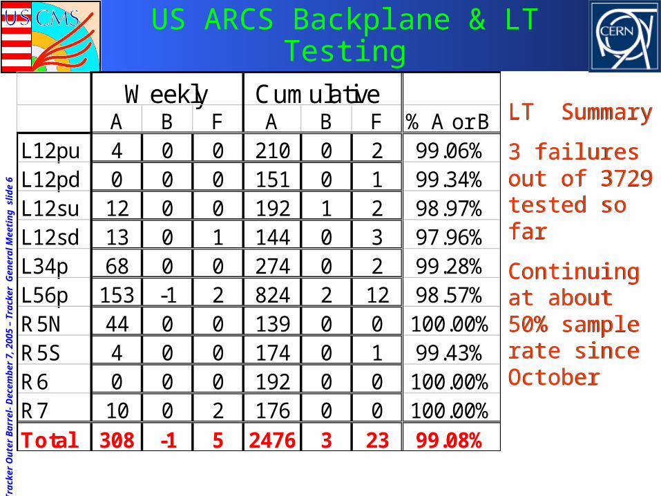
US ARCS Backplane & LT Testing
Weekly CumulativeA B F A B F % A or B
L12pu 4 0 0 210 0 2 99.06%L12pd 0 0 0 151 0 1 99.34%L12su 12 0 0 192 1 2 98.97%L12sd 13 0 1 144 0 3 97.96%L34p 68 0 0 274 0 2 99.28%L56p 153 -1 2 824 2 12 98.57%R5N 44 0 0 139 0 0 100.00%R5S 4 0 0 174 0 1 99.43%R6 0 0 0 192 0 0 100.00%R7 10 0 2 176 0 0 100.00%Total 308 -1 5 2476 3 23 99.08%
LT Summary
3 failures out of 3729 tested so far
Continuing at about 50% sample rate since October
LT Summary
3 failures out of 3729 tested so far
Continuing at about 50% sample rate since October

Tra
cker
Ou
ter
Bar
rel-
Dec
emb
er 7
, 200
5 –
Tra
cker
Gen
eral
Mee
tin
g s
lide
7
Module Assembly Planning
• FNAL: Current rate is 15-18 TOB modules/day.• Finish TOB modules Jan/Feb then TEC R7
• UCSB Current default 15-18 modules/day• Allows time to do L5 and L6 retrofits
• Do mix of TOB and TEC until end of April
• To do list: • Bias connections on some 1,700 modules.
• Wire bonding and ARCS operations (but not LT).

Tra
cker
Ou
ter
Bar
rel-
Dec
emb
er 7
, 200
5 –
Tra
cker
Gen
eral
Mee
tin
g s
lide
8
New problem found
•UCSB• 1 rod with three
modules with saturated channels and one module with high current
• 1 rod with one module with a saturated channel
•Single channels at the edge of wafers
• Always at the very first test (SRT)
•FNAL• 1 DS rod with one module
w/saturated channels
• 1 rod with three modules w/ saturated channels on a non-production rod
• 1 rod had a module w/ saturated channels on a non-production rod
•Groups (~3) of channels in middle of wafer
• Always on MRT after SRT test OK
During tests of several tens of rods, last ~ 2 months

Tra
cker
Ou
ter
Bar
rel-
Dec
emb
er 7
, 200
5 –
Tra
cker
Gen
eral
Mee
tin
g s
lide
9
Damage on input to APV
• Saturated channels show damage on APV input
• Silicon channel itself is OK • Check by bonding to a functioning neighbor APV channel
UCSB mod 6046
FNAL mod 9103

Tra
cker
Ou
ter
Bar
rel-
Dec
emb
er 7
, 200
5 –
Tra
cker
Gen
eral
Mee
tin
g s
lide
10
Corresponding Damage on Sensor
Damage Location
UCSB Module
• Damage is at the edge of the n+ region at boarder of sensor, (at HV), directly under bias bond, (at ground)
• Bias bond is lower than channel bonds
• Nearest signal channel saturated

Tra
cker
Ou
ter
Bar
rel-
Dec
emb
er 7
, 200
5 –
Tra
cker
Gen
eral
Mee
tin
g s
lide
11
Higher magnification(with bias bond moved aside)
No visible damage to APVAPV channel 768 dead
Bias current not changed
No visible damage to APVAPV channel 1 dead
Bias current not changed

Tra
cker
Ou
ter
Bar
rel-
Dec
emb
er 7
, 200
5 –
Tra
cker
Gen
eral
Mee
tin
g s
lide
12
FNAL: same story
• Channel jumper bonds have less clearance than bias bonds
• Damage again seen under bonds corresponding to broken APV channels
• Bond shape asymmetric• Top picture: 2nd sensor
• Where bonds are low
• Bottom picture: 1st sensor
• Bonds higher
• perhaps passivation flawed here?

Tra
cker
Ou
ter
Bar
rel-
Dec
emb
er 7
, 200
5 –
Tra
cker
Gen
eral
Mee
tin
g s
lide
13
Hypothesis
• HV breakdown between metal over n+ and bonds• At UCSB, breakdown to bias bond, since it is lowest
• Nearest channel is then "zapped" through capacitive coupling…
• At FNAL, breakdown to lowest signal bond
• Bonds to PA much higher
• Explains why it is only seen for the jumpers between sensors
Raises some obvious questions:
• Why haven't we seen this before? Could we have missed it?
• How widespread might this issue be?• i.e. How high are our bonds?
• What can we do about it?

Tra
cker
Ou
ter
Bar
rel-
Dec
emb
er 7
, 200
5 –
Tra
cker
Gen
eral
Mee
tin
g s
lide
14
How high are the bonds?
TOB bias wire height
0
50
100
150
200
250
1 2 3 4 5 6 7 8 9 10
um
UCSB bias
FNAL lowest bias
FNAL highest bias
UCSB Sen-Sen
FNAL Sen-Sen
TOB bond clearance over n+ region (Not loop height)
UCSB measurements shown (include some FNAL modules) FNAL measurements ~ agree

Tra
cker
Ou
ter
Bar
rel-
Dec
emb
er 7
, 200
5 –
Tra
cker
Gen
eral
Mee
tin
g s
lide
15
TEC modules built at UCSB
• They appear to be a little bit less vulnerable than TOB modules built at UCSB• Have not checked carefully that the problems reported for TOB
modules do or do not occur for TEC
TEC R5 bias 152 m
150 mTEC R6 bias 138 m
143 mTEC R7 bias 138 m
141 mnew bias 247 m
289 m

Tra
cker
Ou
ter
Bar
rel-
Dec
emb
er 7
, 200
5 –
Tra
cker
Gen
eral
Mee
tin
g s
lide
16
Breakdown study
• Increase HV up to 1000 V on UCSB TOB module. Ramp as fast as possible.
No breakdown
• Plug and unplug HV wire at 1000 V
Breakdown after several tries
• Intentionally lower the bias bond (in steps) and ramp HV for each bond height
Breakdown at 40m height occurred at HV=800 V

Tra
cker
Ou
ter
Bar
rel-
Dec
emb
er 7
, 200
5 –
Tra
cker
Gen
eral
Mee
tin
g s
lide
17
HV transients
• Suspect breakdown is caused by HV transients
• Power supplies are CAEN A132 or A332: (6kV) • All "accidents" happened on A132
• This supply does not have HV limiting
• Monitored for HV transients• No real success
• Saw HV go from 0 to 80V in 100 sec once when 1st establishing SW communication – not reproduced
• See occasional spurious front panel or SW readings up to 8kV
• In at least one case we were looking at HV with a DVM when this occurred and did not see anything

Tra
cker
Ou
ter
Bar
rel-
Dec
emb
er 7
, 200
5 –
Tra
cker
Gen
eral
Mee
tin
g s
lide
18
Initial response
• New modules • Modify bond parameters for max. clearance above n+ region
• Existing UCSB Modules • Remove all sensor-to-sensor bias bonds on and remake them longer
and much higher over n+ region.
• Rod production at UCSB thus temporarily suspended
• Existing FNAL Modules • Inspect sensor-to-sensor bias bonds and pull lowest if less than 200
m above the n+ region
• Rod Testing• All rod test stand HV lines equipped with crowbars and current limits
reduced 95%.
• Continued rod production at FNAL for ~ 4 weeks, with no further accidents

Tra
cker
Ou
ter
Bar
rel-
Dec
emb
er 7
, 200
5 –
Tra
cker
Gen
eral
Mee
tin
g s
lide
19
Further Information
• Our worry - local electric fields could be high enough to cause ionization (corona, partial discharge) even if no sparks.
• What happens? particularly over long periods?
• Therefore decided to carefully inspect modules which did not have breakdown incidents, and which were never mounted on rods
• See localized damage !

Tra
cker
Ou
ter
Bar
rel-
Dec
emb
er 7
, 200
5 –
Tra
cker
Gen
eral
Mee
tin
g s
lide
20
Damage under UCSB bias bonds
Damage on 2nd sensor of all TOB modules!• At minimum, dots seen at edges of guard ring
and n+ metal directly under bias wire.
• At maximum, lines of metal(?) deposited in the area between the guard ring and n+ region. Again, directly under bias wires.
• Beginnings of this trend already appears after 20 min on ARCS test
Guard Ring
Gua
rd R
ing
Guard R
ing
n+ m
etal
n+ m
etal
Tra
cker
Ou
ter
Bar
rel-
Dec
emb
er 7
, 200
5 –
Tra
cker
Gen
eral
Mee
tin
g s
lide
21
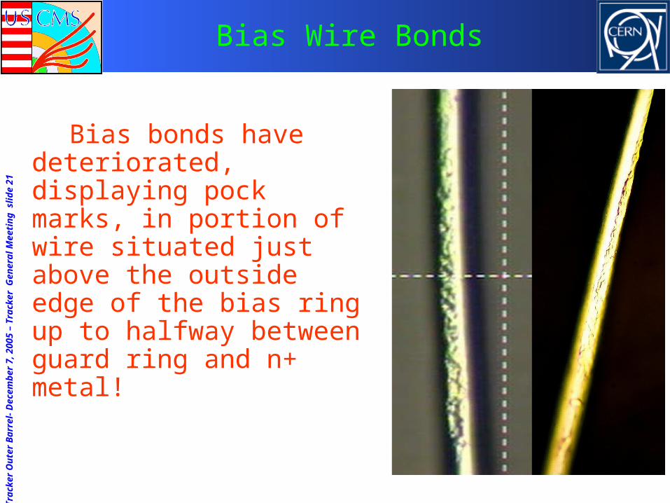
Bias Wire Bonds
Bias bonds have deteriorated, displaying pock marks, in portion of wire situated just above the outside edge of the bias ring up to halfway between guard ring and n+ metal!

Tra
cker
Ou
ter
Bar
rel-
Dec
emb
er 7
, 200
5 –
Tra
cker
Gen
eral
Mee
tin
g s
lide
22
Current status and proposed plan
• Expect problem can br overcome with encapsulation• Study underway at UCSB: 4 groups of sensor to sensor bonds
• High - Low - High – Low
• One High-Low group encapsulated the other not.
• Run overnight in LT
• Pull encapsulant and compare to non-encapsulated region for sensor marks, wire deterioration
• If positive, will start to encapsulate modules • Both PA-Sensor and Sensor-Sensor regions
• Do enough modules to populate one cooling segment of TOB outer layer
• Continue additional studies in parallel• Thermal cycles of encapsulated modules with final wirebond program
• Look for corona with pmt
• Disect and scan discharge burn area with electron microscope

Tra
cker
Ou
ter
Bar
rel-
Dec
emb
er 7
, 200
5 –
Tra
cker
Gen
eral
Mee
tin
g s
lide
23
Meanwhile: UCSB Rod Status
• Last week: No rod production.• Verified that crowbars work as advertised.
• Fuse blows at ~640 V
• Looked for transient voltage spikes from CAEN.
• 2 blown crowbars, both occurred after CAEN front panel showed voltage reading 0 V >400 V in ~2 sec. Also not reproduced after ~15 tries.
• One crowbar modified so that output voltage can be independently monitored (with DVM and/or scope) during test operation.
• New crowbars now in preparation will also have this feature.
Tra
cker
Ou
ter
Bar
rel-
Dec
emb
er 7
, 200
5 –
Tra
cker
Gen
eral
Mee
tin
g s
lide
24
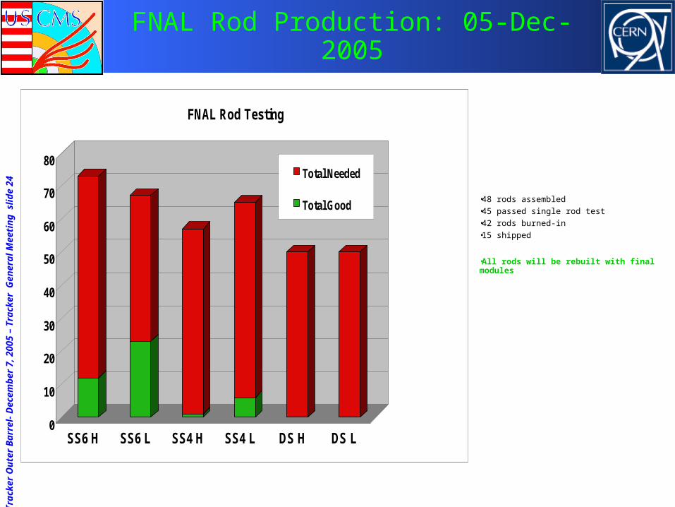
FNAL Rod Production: 05-Dec-2005
0
10
20
30
40
50
60
70
80
SS6 H SS6 L SS4 H SS4 L DS H DS L
FNAL Rod Testing
Total Needed
Total Good •48 rods assembled
•45 passed single rod test
•42 rods burned-in
•15 shipped
•All rods will be rebuilt with final modules

Tra
cker
Ou
ter
Bar
rel-
Dec
emb
er 7
, 200
5 –
Tra
cker
Gen
eral
Mee
tin
g s
lide
25
TOB Integration
• Installation and test of one cooling segment (19 rods)
• Learning/training exercise
• Improved/refined many procedures
• First look at noise performance

Tra
cker
Ou
ter
Bar
rel-
Dec
emb
er 7
, 200
5 –
Tra
cker
Gen
eral
Mee
tin
g s
lide
26
Rod insertion and cabling

Tra
cker
Ou
ter
Bar
rel-
Dec
emb
er 7
, 200
5 –
Tra
cker
Gen
eral
Mee
tin
g s
lide
27
Soldering of cooling lines
Unexpected difficulties with the soldering:
Brass connection pieces more oxidized and dirty than what we were used to.
→ Will prepare the surfaces more carefully.
3 weak solder connections found (10-4 to 10-6 mbarl/s) - among first solder joints.Connections disconnected, cleaned and resoldered:All connections then leak tight (alarm limit at 1x10⁻⁷ mbarl/s)

Tra
cker
Ou
ter
Bar
rel-
Dec
emb
er 7
, 200
5 –
Tra
cker
Gen
eral
Mee
tin
g s
lide
28
Electrical tests
Low noise. The grounding scheme works!
All bad channels found were pre-existing.

Tra
cker
Ou
ter
Bar
rel-
Dec
emb
er 7
, 200
5 –
Tra
cker
Gen
eral
Mee
tin
g s
lide
29
Rod Tests on Barrel
• Noise level is acceptable• Edge channels are often noisy but this will be fixed
with new ICC and associated grounding
• 10% 0ptical connections were not correct
• Problem with exterior connections (not at rod)
• Now have 5 bad out of 342 with 4 from one ribbon
• Some bad modules/rods – one laser with high CMN, several pinholes etc.
• Found all known problematic channels
Tra
cker
Ou
ter
Bar
rel-
Dec
emb
er 7
, 200
5 –
Tra
cker
Gen
eral
Mee
tin
g s
lide
30
Integration exercise
• Went mostly ‘as planned’. A few discoveries:• Need better preparation of solder connections. Solder
equipment also improved.
• Improvements to rod insertion tool
• Handling cables & connections is … time consuming.
• Access to rods will be much worse inside the TST. • When is the best time to go inside?
• The 1st technician team is now trained.

Tra
cker
Ou
ter
Bar
rel-
Dec
emb
er 7
, 200
5 –
Tra
cker
Gen
eral
Mee
tin
g s
lide
31
To do
• Dismount pre-assembled 19 rod cooling segment (segment 2.6.2)
• Start final assembly, again with cooling segment 2.6.2, and train the 2nd technician team
• Preparation of new clean room for integration work• He, dry air, C6F14 lines, tables, etc.
• Improvements to the tooling
• Develop a better work platform

Tra
cker
Ou
ter
Bar
rel-
Dec
emb
er 7
, 200
5 –
Tra
cker
Gen
eral
Mee
tin
g s
lide
32
Rod installation tools
Small improvements to the 1st rod installation tool
Make a 2nd rod installation tool (currently in manufacture in FNAL)
Tra
cker
Ou
ter
Bar
rel-
Dec
emb
er 7
, 200
5 –
Tra
cker
Gen
eral
Mee
tin
g s
lide
33
Tracker Monitoring Workshop
• The workshop was held on Nov. 15, 2005 (vrvs)• Focus was on monitoring tools for tracker I&C at CERN.
• Speakers from FNAL, CERN, INFN/Pisa, UCL/Louvain
• Workshop achieved the goals• Talks on CDF/DØ experience with Si detector commissioning;
lessons learned, useful tools
• Included some thoughts about what might help CMS
• Talks and discussions on
• xDAQ and tools developed for tracker commissioning
• Rod test data and analysis at CERN
• Tracker data handling and monitoring framework and tools
• Remote monitoring/analysis experience at Fermilab for HCAL
• Procedures, communication, collaborative tools
Tra
cker
Ou
ter
Bar
rel-
Dec
emb
er 7
, 200
5 –
Tra
cker
Gen
eral
Mee
tin
g s
lide
34
Tracker Monitoring Workshop: Plans
• Establish communication among interested parties
• Avoid duplication of effort
• Identify and help develop appropriate tools
• Gain experience with the standard DQM software (to be available by spring ’06) and help get it ready for use in I&C
• Establish a group at Fermilab
• Remote monitoring and analysis of data from I&C and to provide feed-back participate in ~real time in data monitoring/analysis and debugging activities
• Help with building and/or improving diagnostics and other essential tools
• Follow-up meetings with I&C, xDAQ and DQM groups

Tra
cker
Ou
ter
Bar
rel-
Dec
emb
er 7
, 200
5 –
Tra
cker
Gen
eral
Mee
tin
g s
lide
35
Summary & Conclusions
• Quickly diagnosed a very serious problem• Will (almost certainly) encapsulate
• Modified rod stands for safety
• Rod production lines now robust
• Integration studies underway• Again, many important lessons learned
• Generally things appear to be in good shape
• Establishing additional qualified manpower will be critical to schedule and quality
• These are very critical times• Though we are weary, we have to keep doing top
quality work

Additional Information

Tra
cker
Ou
ter
Bar
rel-
Dec
emb
er 7
, 200
5 –
Tra
cker
Gen
eral
Mee
tin
g s
lide
37
FNAL & UCSB Inventory – 11/28/05
Hybrids Sensors Frames
FNAL UCSB FNAL UCSBFNA
LUCS
B
ST HPK ST HPK IT ST HPK ST HPK IT
L12sd 0 57 0 204 73
213
541276 735 -
190 498L12su 0 89 0 257 -
L12pd 0 98 0 152 -308 423
L12pu56 187 85 395 -
L34pu52 349
L56pu 0 103 0 216 2 272 5 153 32 -
R5p 0 102 -23 78 -
168
R5s 6 88 68 130
R6 0 70 53 0 223 - 269
R7 0 14 - 0 93 - 282
Tra
cker
Ou
ter
Bar
rel-
Dec
emb
er 7
, 200
5 –
Tra
cker
Gen
eral
Mee
tin
g s
lide
38
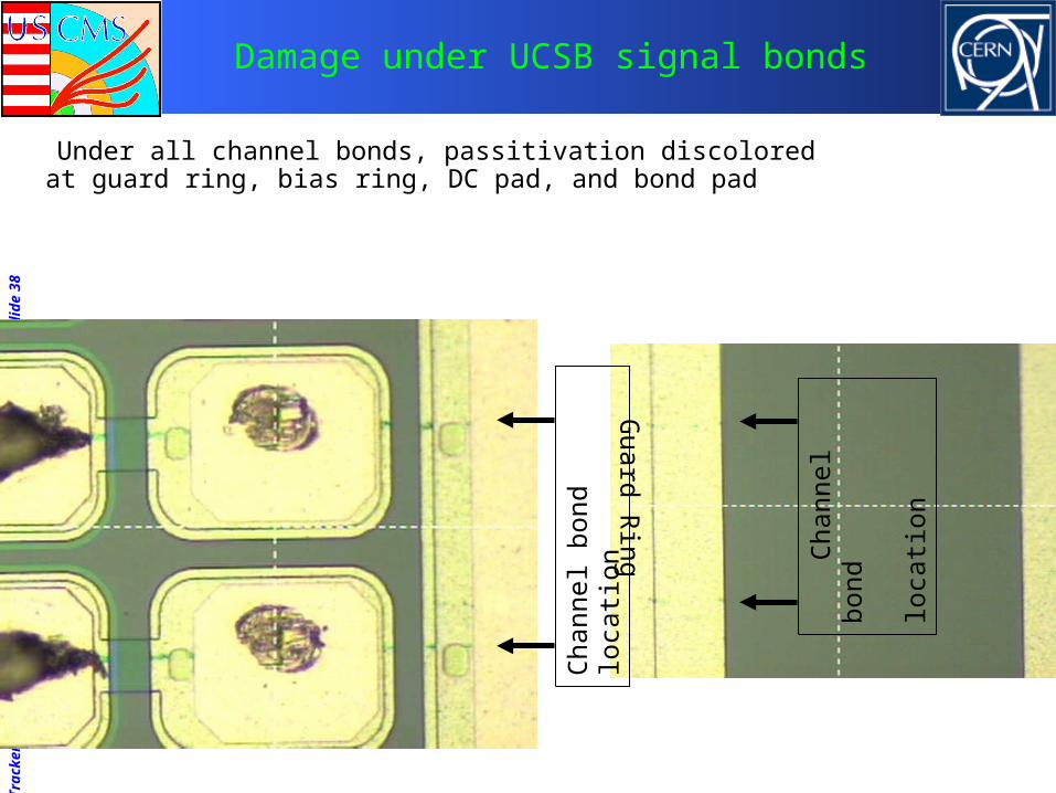
Damage under UCSB signal bonds
Under all channel bonds, passitivation discolored at guard ring, bias ring, DC pad, and bond pad
Guard R
ing
Cha
nnel
bon
d lo
catio
n
Cha
nnel
bon
d
lo
catio
n

Tra
cker
Ou
ter
Bar
rel-
Dec
emb
er 7
, 200
5 –
Tra
cker
Gen
eral
Mee
tin
g s
lide
39
Could we have missed it?
• Arcs and LT tested 1000's of modules and never saw this.• It was not overlooked – no bad channels developed that we did not
understand were due to other problems (e.g. pinholes, shorts, opens)
• This problem showed up on rods• We have less rod experience, but we’ve tested rods for over a year
• Emphasis was on DAQ debug, but we believe we would noticed this

Tra
cker
Ou
ter
Bar
rel-
Dec
emb
er 7
, 200
5 –
Tra
cker
Gen
eral
Mee
tin
g s
lide
40
He leak testing
Three weak solder connections found (10-4 - 10-6 mbarl/s) All were among the first solder joints made.Connections disconnected, cleaned and resoldered:All connections then leak tight (alarm limit at 1x10^-7 mbarl/s)

Tra
cker
Ou
ter
Bar
rel-
Dec
emb
er 7
, 200
5 –
Tra
cker
Gen
eral
Mee
tin
g s
lide
41
To do: Better work platform

Tra
cker
Ou
ter
Bar
rel-
Dec
emb
er 7
, 200
5 –
Tra
cker
Gen
eral
Mee
tin
g s
lide
42
A better work platform

Tra
cker
Ou
ter
Bar
rel-
Dec
emb
er 7
, 200
5 –
Tra
cker
Gen
eral
Mee
tin
g s
lide
43
He Leak check rods
No leaks found (alarm limit 10-8 mbarl/s)