storm water manual
TRANSCRIPT
CITY OF GEORGETOWN ORDINANCE NO. 2002-______
AN ORDINANCE RELATED TO THE AMENDMENT OF THEGEORGETOWN/SCOTT COUNTY SUBDIVISION &
DEVELOPMENT REGULATIONS REGARDING ARTICLE XI –STORM WATER MANAGEMENT
WHEREAS: The existing Subdivision & Development Regulationsrequirements are not satisfying the community’s needs. The regulationrequirements must be updated to reflect the current professionalthinking, engineering principles and best management practices toaddress storm water management. Scott County boasts some of the mostprestigious streams in Kentucky. North Elkhorn, South Elkhorn and EagleCreeks are used extensively for fishing and recreation. In addition to thesestreams, Georgetown and Scott County obtains the majority of its waterfrom the Royal Spring Aquifer, a natural resource unique in Kentucky,which is fed by groundwater recharge. It is important to safeguard thesewaterways from pollutants and changes in their ecology.
The Storm Water Manual is only one part of the overall storm water plan.The manual, once adopted, will become an integral part of the City ofGeorgetown’s Phase II permit. The City has contracted with an outsidefirm for mapping and location of all drainage features within theurbanized area. This work and the required permit must be filed with theKentucky Division of Water by March 2003.
All new developments, including those that require substantialrenovations or expansions, within the urbanized area will be required toadhere to the new manual. Every time that a piece of land is developed,certain and expected changes occur. Changes potentially in the amount ofgroundwater recharge and even surface run-off can be impacted. The newregulations hope to reduce and offset those issues. Anytime silt andconstruction debris are allowed to leave a construction site, theeffectiveness of constructed drainage systems, including catch basins,drain pipes, swales and easements, is reduced.
The intent of this proposed ordinance is to provide an appropriate meansto maintain the integrity and durability of existing and proposed stormwater systems within our neighborhoods and the City of Georgetown;

WHEREAS: This proposed amendment to the Georgetown-Scott CountySubdivision & Development Regulations has been submitted to thecitizens through a properly advertised public hearing before theGeorgetown-Scott County Planning and Zoning Commission conducted attheir August 8, 2002, and September 12, 2002, public meeting. TheCommission voted unanimously to recommend the adoption of thisamendment to the City Council of Georgetown;
NOW, THEREFORE, BE IT ORDAINED BY THE COUNCIL FOR THE CITY OFGEORGETOWN, KENTUCKY, as follows:
SECTION ONE: NEW PROVISIONS.
[New language is underlined. Language which is unchanged is notmarked. Superseded language is shown as stricken.]
1. A. -1. unchanged2. unchanged3. unchanged4. unchanged5. unchanged6. unchanged7. unchanged
B. -1. unchanged2. unchanged3. unchanged4. unchanged5. unchanged6. unchanged7. for all detention basins and inflow and outflow structures:
storm water facilities and inflow and outflow structuresmust be evaluated to include, if warranted, the following:
a. unchangedb. design hydrographs of inflow and outflow fo the25-year, 24-hour or 10-year one hour events for thesite under existing and developed conditions;c. demonstration that the floor of the basin will beconstructed and compacted to provide at least a 2%minimum slope to the outlet pipe to ensure thatdetained waters fully drain and do not create a

health and safety hazard or visual nuisance.d. Demonstration that overflow for a storm in excessof the design capacity will be provided and designedto function without specific attention as part of theexcess stormwater passage.b. provide anti-seep collars details for storm waterimpoundment facilities that have dewatering timesgreater than 48 hours, or permanent pools.c. dewatering features, such as valve structuresand/or underlying drain systems, are to be includedfor facilities other than standard detention designs,for example, permanent pools, constructedwetlands, infiltration basins, bioretention areas, etc.d. water budget analyses are to be done for allstorm water facilities with permanent pools.e. outlet pipes for all storm water impoundmentsare to be reinforced concrete pipes.f. construction plans are to include all compactionrequirements and tolerances for all proposed waterimpoundments, dams, and channel/streamcrossings.g. provide a means of access to all proposed stormwater facilities.
8. storm water impoundment facilities are to serve astemporary sediment basins until the contributingdrainage area exceeds 90 percent build out. At that time,they shall be converted over to the approved postdeveloped storm water facility.
C. Storm water manual (note all of the following language is newand to be added)
1. Requirements: Developments that occur within ScottCounty are required to provide the Planning Commissiona Storm Water Management Plan that addresses all theelements of the hydrologic cycle. These elements include,and are not limited to, the following:
a. Groundwater rechargeb. Water quality protectionc. Channel protectiond. Water quantity control
The plan is to include construction drawings showing all

details on how to construct the proposed improvementsand a drainage report providing all necessary calculationsto comply with each element. All storm watermanagement plans are to be reviewed and approved bythe Planning Commission Engineer. The Georgetown CityEngineer must also approve plans for developments thatare within the Georgetown City Limits.
Construction Plans: All Storm Water Management Plansshall provide details related to all aspects of theconstruction. Developments are to be designed toensure that controls are in place that would preventor minimize water quality impacts. Designers are todevelop and implement strategies, which include acombination of structural and/or non-structural BestManagement Practices (BMPs) appropriate for thecommunity. The plans must also ensure adequatelong-term operation and maintenance of BMPsthrough notes or labels on construction drawings,Final Subdivision Plats, and Final Development Plans.Drainage Reports: Studies are required to providecalculations supporting the use of the BMPsspecified in the plans. These studies are to besubmitted in conjunction with the ConstructionPlans for proposed developments. The following is alist of minimum criteria to be included in all drainagereports:
1. Summary tables outlining all hydrologicquantities needed to support the storm watermanagement plans.
2. Soil survey maps showing the existing soilconditions for a proposed development.
3. Ponding elevations for each of the proposedstorm water structures, storm water facilities,and closed contour areas.
4. Flow depths for all open channel conditionsthat are a part of the proposed plans.
5. Identification of all the swales, diversionditches, roadway ditches, 100 year drainageways, and floodplains.
6. Evaluation of storm water systems that receive
runoff from proposed developments; systemsbeing defined as any type of structure or openchannel that conveys runoff.
7. Pre and postdeveloped watershed mapsshowing all parameters used by designers toproduce their storm water plans.
8. Maps that show all subcatchments draining toeach proposed structure.
9. Label the analysis points where the studyterminates. All points of analysis are to be setto evaluate the potential of compounding peakflow conditions downstream of developments.Analysis points are to be approved by thePlanning Commission Engineer.
Additional Requirements: All developments mustalso incorporate the following criteria into theirdesigns:
a. Finish floor elevations for proposed singlefamily and multifamily residential units are tobe at least two feet above the 100-year watersurface elevations of all waterways, overflowconditions, overland flow areas, and pondingareas.
b. Commercial facilities are to be evaluated forprotection from 100 year flooding conditions.
c. Designs are not to include any fill to be placedin 100 year drainage ways and floodplains,unless proposed construction complies withArticle XII, Section 1200 of the Subdivision andDevelopment Regulations, and any and allpermits from the Federal, State, and Localagencies are obtained prior to construction.
d. Other than what is described in item #3, anyand all permits required by Federal, State, andLocal agencies for developments must beobtained prior to the commencement of thatprocess regulated by the permits.
2. Groundwater Recharge: Base flows of local streams andwaterways are fed by groundwater sources.Developments can cause changes in the amount of waterthat would be used to support base flows. As the

impervious area of a site increases, so does the volume ofrunoff. To maintain adequate base flows and streamecosystems, developments must incorporate practices intheir storm water management plan to provide fortreated groundwater recharge. The amount of rechargethat a site is capable of providing depends on topographicfactors such as slope, types of vegetation, hydrological soilgroups, and locations of rock layers. The average annualrecharge volume for a site can be estimated by taking theaverage annual recharge rate of the hydrological soilgroup(s), dividing that by the average annual rainfall(44.05 inches), and then multiplying that result by 90percent. The following table provides a summary of therecharge requirements:
HydrologicSoil Group(HSG)
Average AnnualRecharge Volume(in/yr)
Soil SpecificRecharge (Sin)(in)
A 18 0.37
B 12 0.25
C 6 0.12
D 3 0.06
Scott County Soils
Soil SeriesNRCSHSG
DepthtoBedrock(ft)
SeasonalHighWaterTable(ft)
Permeability(in/hr)
Suitabilityas RoadFill
Ashton B >4 >5 0.6-2.0 Fair
Cynthiana D 1-1.5 >50.6-2.0, 0.2-0.6
Poor
Dunning[1]
D >3.5 0-0.5 0.6-2.0, <0.2 Poor
Eden C 1.5-3.5 >5 0.6-2.0, <0.2 Poor
Faywood C 1.5-3.5 >3.50.6-2.0, 0.2-0.6
Poor
Huntington

[1] B >4 >3 0.6-2.0 Fair
Lowell C >3.5 >50.2-0.6, 0.6-2.0
Poor
Maury B >5 >50.6-2.0, 0.6-6.0
Fair, Poor
McAfee C 1.5-3.5 >3.50.2-0.6, 0.6-6.0
Poor
Newark [1] C,D >4 0.5-1.5 0.6-2.0 Fair, Poor
Nicholson C >5 1.5-2.5 <0.2, 0.6-2.0 Poor
Nolin [1] C 4 3 0.6-2.0 Fair
DisturbedSoil
D - - - -
Note: S(in) = (S)(P).
(1): Subject to common flooding.
References:
2000 Maryland Stormwater Design Manual VolumesI & II.Soil Survey of Scott County, Kentucky.Urban Hydrology for Small Watersheds, TR-55.LFUCG Stormwater Manual, 1999
The soil specific recharge is determined by calculating avolume to be treated and infiltrated by a structuralpractice or by a percent area method involving a non-structural practice. The following formula is to be used fora structural practice:
GRV = Groundwater recharge volume, acre-ft.Sin = Soil specific recharge, in.I = Percent impervious, %.A = Total area of site, acre.
Examples of structural practices that can be used forgroundwater recharge are bioretention areas, infiltrationfacilities, terraformed berms, and infiltration swales.
Since Scott County is in a karst region, designers that
intend to use structural practices for groundwaterrecharge must evaluate potential areas to ensure thatthese proposed facilities would be adequate and not havean adverse impact on surrounding areas, such asincreasing the water table. Designers are to ensure thatthe groundwater recharge volume is to exit proposedfacilities through natural infiltration or a designed outlet,and that the volume is treated by BMPs prior toinfiltration. Dewatering times for structural practicesshould not exceed 48 hours. Groundwater rechargerequirements may be waived for redevelopments only ifapproved by the Planning Commission Engineer.
3. Water Quality Protection: The water chemistry of runoffis extremely important to the health of creeks andstreams. When enough rainfall occurs, runoff from landareas is transported from these sites to drainage ways.These drainage ways eventually reach the creek systemsof Scott County. Depending on the types of sites,pollutants are transported by the force of the runoff or byits physical factors such as temperature and pH level.Water quality BMPs are to be used to the maximumextent practical to minimize these impacts and to treatrunoff from all proposed impervious surfaces.
For adequate treatment, 90 percent of the average annualrainfall must be treated by stormwater BMPs. Rainfallrecords from GMWSS water treatment plant shows thatapproximately 90 percent of total storm events occurredwith 1 inch of rainfall or less.

The following equation is used to determine the waterquality volume needed to be treated for a development:
WQV = Water quality volume, acre-ft.P = 90 percent of total storm events, 1 inch.I = Percent impervious, %.A = Total area of site, acre.
The following table [1] lists the amounts of imperviousareas that can expected from different types ofdevelopment, and the water quality depth in inches pergiven area:
Land Use/CoverType
AverageImpervious Cover(%)
Water QualityDepth (in)
Paved parking lots[2]
100 0.95
Roofs 100 0.95
Driveways 100 0.95
Streets and roads[2]
100 0.95
Commercial andbusiness districts
85 0.82

Industrial 72 0.70
Town houses 65 0.64
Residential 1/8 acrelots or less
65 0.64
Residential 1/4 acrelots
38 0.39
Residential 1/2 acrelots
30 0.32
Residential 1/2 acrelots
25 0.28
Residential 1 acrelots
20 0.23
Residential 2 acrelots
12 0.23
[1]: Based on NRCS TR-55 modeling criteria.
[2]: Excluding right-of-way.
Note: Water quality volume must be accounted for by storm water credits and/or BMPs.
Targeted Pollutants: Designers are to use structuraland non-structural BMPs to the maximum extentpractical to treat the water quality volume. Individualtreatments, or a combination of BMPs, can be usedto achieve this goal.
Different land uses can generate different types ofrunoff pollutants. For instance, a proposed refuelingstation would produce a higher concentration ofhydrocarbons per acre than a proposed residentialsubdivision. Selection of BMPs should be based onthe anticipated pollutants for a site. Some examplesof typical pollutants for different applications are:
1. Residentiali. Setteable solidsii. Total suspended solidsiii. Nitrogeniv. Phosphorousv. Metals
2. Commercial and industriali. Hydrocarbons

ii. Trashiii. Setteable solidsiv. Total suspended solidsv. Nitrogenvi. Phosphorousvii. Metals
Additional Storm Water Controls for SpecificCommercial Areas: Specific design criteria for thefollowing types of development are to be used:
1. Restaurants/grocery storesi. Dumpster pad areas are to drain into the
proposed storm sewer system.ii. A pretreatment device is to be used at
dumpster locations that drain into thestorm sewer system.
iii. Pretreatment device is only to receivesurface water from dumpster pad.
iv. Configuration and pretreatment to beapproved by Scott County HealthDepartment.
v. Operation and maintenance criteria to beincluded in the Construction Plans andFinal Development Plans.
2. Refueling stationsi. Canopy refueling areas are to drain to the
sanitary sewer.ii. Grade elevations are set to ensure that
the only surface area draining into thesanitary system is from the pad itself.
iii. No external rainwater can drain into thesanitary lines.
iv. A pretreatment device is to be used fordischarges draining into the sanitarysystem.
v. Configuration and pretreatment to beapproved by GMWSS.
vi. Operation and maintenance criteria to beincluded in the Construction Plans andFinal Development Plans.
3. Repair shops/oil change facilities/car lotsi. Interior vehicle areas are to drain into the

sanitary system.ii. A pretreatment device is to be used for
discharges draining into the sanitarysystem.
iii. Configuration and pretreatment to beapproved by GMWSS.
iv. Operation and maintenance criteria to beincluded in the construction drawings andFinal Development Plans.
4. Automotive and truck wash facilitiesi. Covered wash bays are to drain into the
sanitary sewer system.ii. Grade elevations set to ensure that the
only surface areas draining into thesanitary system is from the baysthemselves.
iii. No external rainwater can drain into thesanitary lines.
iv. A pretreatment device is to be used fordischarges draining into the sanitarysystem.
v. Configuration and pretreatment to beapproved by GMWSS.
vi. Operation and maintenance criteria to beincluded in the construction drawings andFinal Development Plans.
Treated groundwater recharge volumes can counttowards the required water quality volumes;however, neither the groundwater recharge or waterquality volumes are to be included in the channelprotection and the water quantity control portion ofthe regulations.
4. Channel Protection: Developments that requireimpervious areas and compacted fills reduce the amountof rainfall that previously infiltrated into the underlyingsoils. The rainfall is then converted into runoff, whicheventually drains into the Scott County creek systems.Frequent rainfall events help to shape stream geometries.Uncontrolled events after development can causedegradation to channel areas. To protect channels from

this degradation, developments are to provide extendeddetention for the 1 year/ 24 hour event, and allow therunoff produced to dewater over a 12 hour period. Stormwater facilities designed for this condition will release flowat a rate not to exceed erosive flow rates in downstreamchannels. Channel protection may be waived but notlimited to proposed sites that have less than 2 cfs for thepost developed state.
Designers are encouraged to protect channel and streamareas by not designing developments that require fill inheadwater stream channels, to within 50 feet of thebankfull conditions (1.5 to 2 year return periods) of minorwaterways, and floodplains. Developments that utilize thisoption may qualify for density credits or otherconsiderations similar to a Planned Urban Development(PUD).
Channel and stream areas that are disturbed due tograding and/or other construction activities must bestabilized and comply with Article XII, Section 1200 of theSubdivision and Development Regulations.
References:
2000 Maryland Stormwater Design Manual VolumesI & II. Center for Watershed Protection.
5. Water Quantity Control: Typically with development, thevolume of runoff increases due to the addition ofimpervious areas, the compaction of soil materials, andremoval of vegetative cover. Some rainfall that oncepercolated into the ground would now travel over thesurface. Developments must provide stormwater featuresthat reduce the peak flow rates after development towhat the runoff rates were prior to construction. Inaddition to the 1 year channel protection requirement,storm events that need to be adhered to are the 10, 25,and 100 year/ 24 hour events. Rainfall intensities for thoseevents are to be taken from Division of Water EngineeringMemorandum No. 2, current edition or most recentversion. In the past, there have been storms thatexceeded these design storm events. Designers areencouraged to analyze proposed developments with such

rainfall intensities, if they feel that it is necessary for safeguarding any proposed infrastructure.
Storm Sewer Design: Proposed storm sewers systemsthat have the potential of being maintained by anymunicipality or government utility in Scott Countymust adhere to the following guidelines:
1. All proposed storm lines are to be reinforcedconcrete pipe (RCP), ADS-N12 or high densitypolyethylene equivalent, A-2000, or aluminizedtype II corrugated metal pipe (CMP) withbituminous coating. Please note that CMP canonly be used when a designer calls for a 48inch line or greater in an urbanized area withthe approval of the Planning CommissionEngineer and City Engineer. CMP is notpermitted in rural areas.
2. Minimum pipe diameter for proposed lines is12 inches.
3. The maximum length between any stormsewer structures, serving less than a 48 inchline, is 300 feet.
4. Bedding details and joint specifications are tobe provided with all construction drawings andshall comply with manufacturingrecommendations.
5. A storm sewer structure must be used if aproposed storm line extends beyond themaximum length, is altered in horizontal orvertical alignment, or changes in pipe material.Structures are also to be used at the beginningand ending points for proposed storm lines.
6. Proposed systems are to be designed to handlethe 10 year/ 24 hour event capacity with noflow above crown of pipe. Flow interception forstructures must be based on bypassconditions. No proposed system is tosurcharge in the 100 year/ 24 hour event.
7. Designers are to design storm sewers thatprevent the 100 year/ 24 hour runoff fromcrossing roadway crowns for local andcontinuous streets. For collectors and arterials,

runoff spread and ponding are restricted to 6feet from the face of curb in the 10 year/ 24hour event.
8. 100 year/ 24 hour water surface elevations areto be determined for all proposed storm sewerstructures, such as headwalls and surfaceinlets.
9. In residential subdivisions that include curband gutter as part of their roadway design,proposed storm lines are to be daylighted atthe rear of proposed lots.
10. Overflow swales are to be provided at saglocations in commercial and residentialsubdivisions.
11. The Planning Commission Engineer and PublicWorks Department or equivalent must approvethe types of structures proposed for stormwater systems that could be maintained by amunicipality of Scott County.
Culverts and Bridges: Proposed channel and streamcrossings are to include a means to convey the 100-year flow. Culverts are typically used in situationswhere drainage ways do not have any base flowsassociated with them. Head conditions occur on theupstream side to force the peak flow through thestructure(s). Proposed culverts are to be designed sothat the 100-year water surface elevation is one footbelow the overtopping elevation of theembankment. Bridge structures are to be used atcreek and stream crossings where base flowconditions do exist (base flow being defined as waterbeing present in channel and stream areas duringdry weather conditions). These structures are to bedesigned to convey the 100-year flow rateunimpeded, and allow the 100-year water surfaceelevation to be one foot below the bottom of theslab. All proposed bridges are to be certified by thedesigner after construction. Prior to construction allpermits are to be obtained from Corps of Engineersand/or Division of Water, if applicable.

Other design considerations that apply to culvertsand bridges are listed in the following:
1. Live load considerations for anticipatedconstruction traffic, fire service vehicles, refusetrucks, commercial vehicles, etc.
2. Public protection for pedestrian and bicycletraffic, if applicable.
3. Headwalls for the upstream and downstreamsides of proposed culverts. Fences or railingare to be provided for headwall that are for 30inch lines or greater.
4. Railing design for bridges.5. End treatments for culverts to minimize
erosion and sediment transport.6. Scouring protection for bridge piers and
abutments.7. Fish passage.8. Streambank stabilization designs for backwater
areas and accelerated flows downstream.
There are areas within Scott County, particularly inthe north, where existing roadways are already inplace and lying in the floodplain. In situations whereroads must be improved due to development, anyportion of the roadway that is flooded by the 100year event or less must be reconstructed to providea concrete cap with a footer design on the upstreamside, to reduce the potential of a roadway beingwashed out.
Open Channel Design: Developments that use openchannels to convey runoff must adhere to thefollowing guidelines:
1. Convey the 100 year event.2. Designs not to exceed the channel lining’s
critical shear force and permissible velocity inthe 10 year event.
3. Select the appropriate roughness values forproposed channels.
4. Provide any armoring needed for hydraulicjump and bend conditions.

6. Storm Water Credits: Storm water credits are waterquality reductions permitted through specific site designcriteria. These credits are established to help reduce theimpacts on Scott County’s stream systems. The credits arecalculated based on the procedures outlined andsubtracted from the water quality requirements for adevelopment.
The following is a list of the stormwater credits that arepermitted for this community:
1. Filter strips2. Vegetated channels3. Riparian buffers4. Terraformed Areas5. Rooftop disconnections6. Modular/porous pavements
Note: Storm water credits are set to encourage "greener" site designs; however, they are notintended to be a substitution for the water quality protection of the regulations. All drainagefrom proposed impervious areas must be treated by a storm water BMP.
1. Filter Strips: Filter strips are undisturbed grass areasthat receive runoff from a development in the formof sheet flow. It is important to note that the filterarea must remain undisturbed during constructionto allow natural percolation to occur.
Credit definition:1. Impervious areas draining to the filter
strip are deducted from the totalimpervious area used to determine thewater quality volume.
2. An additional 0.075 acre-ft per acre offilter strip is also deducted from theremainder of the water quality volume.
Credit criteria:1. Minimum filter strip widths are 50 feet.2. Runoff draining across filter strips shall be
in the form of sheet flow only.3. The maximum contributing length
draining to filter strips shall be 150 feetfor residential development and 75 feetfor commercial development. Designersare permitted to design filter strips to

treat larger areas as long as they followthe design procedure outlined forRiparian Buffers.
4. Slopes greater than 5 percent are toincorporate a means by which runoff isdispersed into sheet flow, for example, alevel spreader or 30 feet grass buffer.
5. Filter strips near channels or drainageways are to be set outside bankfullconditions.
6. The infiltration rate for the underlying soilmust not be less than 0.25 in/hr.
7. Areas draining to filter strips that includerooftops of homes and buildings musthave notes on Final Subdivision Platsand/or Final Development Plans statingthat the roof drains are to be directedtowards the filter strip areas.
8. Filter strips shall be set in easements, orin some other means for protection, onFinal Subdivision Plats and/or FinalDevelopment Plans.
2. Vegetated Channels: Vegetated channels can be usedfor water quality treatment. These types of channelsapply to roadway ditches, drainage ways in the rearof lots, conveyance systems for parking lot drainage,etc.
Credit definition:1. Impervious areas draining through
vegetated channels are deducted fromthe total impervious area used todetermine the water quality volume.
2. An additional 0.25 acre-ft per acre ofchannel area needed to convey the oneinch storm event is also deducted fromthe remainder of the water qualityvolume.
Credit criteria:1. The geometry of the channels must be
either parabolic or trapezoidal.2. Channel side slopes are not to exceed 3:1.
3. The velocity of flow in the channel mustbe 1.0 feet per second or less for therunoff produced by the one inch stormevent.
4. The 10 year/ 24 hr event is not to exceedthe tractive force or permissible velocityof the vegetative cover or the underlyingsoil, whichever is greater.
5. No headwalls are to be in the direct pathof the water quality discharge areas.
6. The infiltration rate for the underlying soilmust not be less than 0.25 in/hr.
7. Areas draining to vegetated channels thatinclude rooftops of homes and buildingsmust have notes on Final SubdivisionPlats and/or Final Development Plansstating that the roof drains are to bedirected towards the open channel areas.
8. Channels shall be set in drainageeasements on Final Subdivision Platsand/or Final Development Plans, statingthat there will be no obstructions orstructures permitted in the easementsincluding fences.
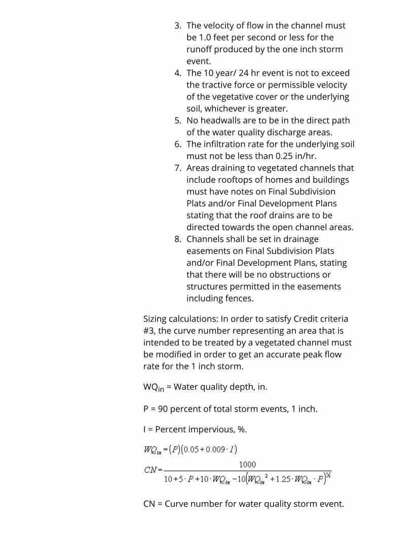
Sizing calculations: In order to satisfy Credit criteria#3, the curve number representing an area that isintended to be treated by a vegetated channel mustbe modified in order to get an accurate peak flowrate for the 1 inch storm.
WQin = Water quality depth, in.
P = 90 percent of total storm events, 1 inch.
I = Percent impervious, %.
CN = Curve number for water quality storm event.

References:
Design of Stormwater Filtering Systems 1996. Center for WatershedProtection.
3. Riparian Buffers: This credit applies to developmentsthat incorporate riparian buffer practices as a part ofits design. The criteria are similar to filter stripsexcept that it is a higher credit for water qualityquantity.
Credit definition:1. Impervious areas draining to the filter
strip are deducted from the totalimpervious area used to determine thewater quality volume.
2. An additional 0.25 acre-ft per acre ofbuffer is also deducted from theremainder of the water quality volume.
Credit criteria:1. Runoff draining across riparian buffers
shall be in the form of sheet flow only.2. The velocity of flow in the in the buffers
must be 1.0 feet per second or less forthe runoff produced by the one inchstorm event.
3. Slopes greater than 5 percent are toincorporate a means by which runoff isdispersed into sheet flow, for example, alevel spreader or 30 feet grass buffer.
4. Riparian widths are to be based on aresidence time of 9 minutes.
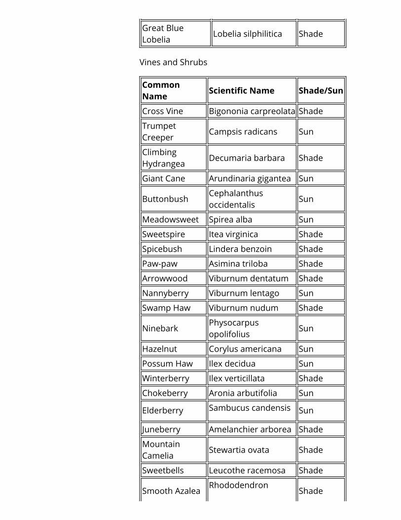
5. Vines and shrubs are to be planted with aminimum density of 1700 stems per acre(one planting per 25 square feet at 5 feeton center), and trees planted at 450stems per acre (one planting every 100square feet at 10 feet on center).
6. For diversity, six or more species from theplanting list on pages 13 to 15 must beused for each riparian design.
7. Riparian buffers near channels ordrainage ways are to be set outsidebankfull conditions.
8. The infiltration rate for the underlying soil

must not be less than 0.25 in/hr.9. Areas draining to riparian buffers that
include rooftops of homes and buildingsmust have notes on Final SubdivisionPlats and/or Final Development Plansstating that the roof drains are to bedirected towards the riparian bufferareas.
10. Riparian buffers shall be set ineasements, or in some other means forprotection, on Final Subdivision Platsand/or Final Development Plans.
Sizing calculations:
Q = Flow rate, cfs.
n = Manning’s roughness (0.24 for grass buffers, 0.35for forested buffers).
A = Cross sectional area, sf.
R = Hydraulic radius, ft.
S = Channel slope, ft/ft.
T = Parallel length of buffer to bank.
y = Depth of flow (0.5 to 1.0), in.
V = Flow velocity, fps.
W = Riparian buffer width, ft.

t = Resident time (9), min.
Planting list:
Herbaceous Ground Cover
Common Name Scientific Name Shade/Sun
River OatsChasmanthiumlatifolia
Shade
Indian Grass Sorgastum nutans Sun
Switch Grass Panicum virgatum Sun
Redtop Agrostis alba Sun
DeertonguePanicumclandestinum
Shade
BroomsedgeAndropogonvirginicus
Sun
Big Blue Stem Andropogon gerardii Sun
Frank's Sedge Carex Sun
Gray's Sedge Carex grayii Shade
Soft Rush Juncus effusus Sun
Flat Sedge Cyperus strigosus Sun
Lady FernAthyrium felix-femina
Shade
Sensitive Fern Onoclea sensibilis Shade
Cinnamon FernOsmundacinnamomea
Shade
CommonBoneset
Eupatoriumperfoliatum
Sun
Golden Ragwort Senecio aureus Shade
WrinkledGoldenrod
Solidago rugosa Sun
Tall Goldenrod Solidago gigantea Sun
Beard Tongue Penstemon hirsutus Shade
Monkey Flower Mimulus ringens Shade
Cardinal Flower Lobelia cardinalis Shade
Great BlueLobelia
Lobelia silphilitica Shade
Vines and Shrubs
CommonName
Scientific Name Shade/Sun
Cross Vine Bigononia carpreolata Shade
TrumpetCreeper
Campsis radicans Sun
ClimbingHydrangea
Decumaria barbara Shade
Giant Cane Arundinaria gigantea Sun
ButtonbushCephalanthusoccidentalis
Sun
Meadowsweet Spirea alba Sun
Sweetspire Itea virginica Shade
Spicebush Lindera benzoin Shade
Paw-paw Asimina triloba Shade
Arrowwood Viburnum dentatum Shade
Nannyberry Viburnum lentago Sun
Swamp Haw Viburnum nudum Shade
NinebarkPhysocarpusopolifolius
Sun
Hazelnut Corylus americana Sun
Possum Haw Ilex decidua Sun
Winterberry Ilex verticillata Shade
Chokeberry Aronia arbutifolia Sun
Elderberry Sambucus candensis Sun
Juneberry Amelanchier arborea Shade
MountainCamelia
Stewartia ovata Shade
Sweetbells Leucothe racemosa Shade
Smooth AzaleaRhododendron
Shade

arborescens
Silky Dogwood Cornus amomum Sun
RedosierDogwood
Cornus stolonifera Shade
Rough-leafDogwood
Cornus drummondii Shade
PagodaDogwood
Cornus alternifolia Shade
Smooth Alder Alnus serrulata Sun
Sandbar Willow Salix interior Sun
Silky Willow Salix sericea Sun
Dwarf WillowSalix humilis var.macrophylla
Sun
Pussy Willow Salix discolor Sun
StreamcoWillow
Salix purpurea Sun
Bankers Willow Salix x cotteti Sun
Heart-leafWillow
Salix rigida Sun
Trees
CommonName
Scientific NameHeight(ft)
Spread(ft)
Black Willow Salix nigra 60-100 50-85
Boxelder Acer negundo 30-60 25-50
Red Maple Acer rubrum 50-100 20-40
Silver MapleAcersaccharinum
50-80 35-50
Green AshFraxinuspennsylvanica
50-60 30-40
White AshFraxinusamericana
80 65
Red Elm Ulmus rubra 70 55
Silverbell Halesia carolina 30-40 20-35
Diospryros

Persimmon virginiana 20-70 10-40
River Birch Betula nigra 40-70 30-60
Black Gum Nyssa sylvatica 30-90 20-30
HackberryCeltisoccidentalis
40-70 40-50
CottonwoodPopulusdeltoides
75-100 50-75
Sweet GumLiquidambarstyraciflua
50-75 40-50
Tulip PoplarLiriodendrontulipifera
60-90 30-50
SycamorePlantanusoccidentalis
75-100 50-75
AmericanBeech
Fagusgrandiflora
50-90 40-75
IronwoodCarpinuscaroliniana
30 30
Yellow BuckeyeAesculusoctandra
70-90 40-55
ShellbarkHickory
Carya lacinosa 70-100 50-75
ShagbarkHickory
Carya ovata 70-100 45-65
Pecan Carya illinoensis 100 70
Black Walnut Juglans nigra 70-90 45-60
Bur OakQuercusmacrocarpa
70-100 75-90
Pin OakQuercuspalustris
50-90 25-45
Swamp Oak Quercus bicolor 60-70 30-35
SwampChestnut Oak
Quercusmichauxii
60-80 40-55
References:
Riparian Buffers Strategies for Urban

Watersheds, 1995.LFUCG Stormwater Manual, 1999.
4. Terraformed Areas: Terraformed areas are placeswithin a development that have been graded topromote stormwater infiltration, such as terracingand berming. Runoff is retained within a bermedarea and allowed to percolate into the soil. Bermedswales, storage areas, and side-saddleimpoundment areas are examples of thisstormwater practice.
Credit definition:1. The runoff volume, impounded by
terraformed areas, is deducted from thegroundwater recharge and water qualityvolumes.
2. An additional 0.25 acre-ft per acre ofterraformed area is also deducted fromthe remainder of the water qualityvolume
Credit criteria:1. Slopes greater than 5 percent are to
incorporate a means by which runoff isdispersed into sheet flow, for example, alevel spreader or 30 feet grass buffer.
2. Terraformed areas near channels ordrainage ways are to be set outside the10 year water surface elevation areas.
3. The infiltration rate for the underlying soilmust not be less than 0.25 in/hr.
4. Areas draining to terraformed areas thatinclude rooftops of homes and buildingsmust have notes on Final SubdivisionPlats and/or Final Development Plansstating that the roof drains are to bedirected towards the terraformed areas.
5. Terraformed areas must drain within 48hours.
6. Terraformed areas shall be set ineasements, or in some other means forprotection, on Final Subdivision Platsand/or Final Development Plans.

5. Rooftop Disconnections: Downspouts from homes forsingle family detached developments includingduplexes that do not tie into a storm sewer, or draindirectly to impervious areas, will have a credittowards the water quality calculations.
Credit definition:1. Rooftop areas draining directly across
yard areas are deducted from the totalimpervious area used to determine thewater quality volume.
2. The maximum credit may not exceed roofareas of typical homes for proposedresidential developments.
Credit criteria:1. Yard areas receiving rooftop runoff are to
be at least ⅓ of the roof areas.2. Discharges must at least travel across 30
feet of grass areas before reaching anyimpervious surfaces.
3. This credit cannot be counted if thedesign for the proposed developmentalready takes into account a BMPtreatment for drainage areas that includeproposed homes.
4. Rooftops draining onto yard areas musthave notes on Final Subdivision Platsand/or Final Development Plans statingthat the roof drains are to be directedtowards the yard areas.
6. Modular/Porous Pavements: Modular/porouspavement designs can be used for developments topromote infiltration of runoff. The performance ofthese pavements will depend on the application forwhich they are used, the construction parameters,and the manufacture’s specifications. These designsare permitted in commercial and industrial areas,only upon the review and approval by the PlanningCommission.
Credit definition:1. Areas using modular/porous pavements
will be treated as pervious areas for the

purposes of calculating groundwaterrecharge, water quality, and peak flowrates.
Credit criteria:1. Installation is to be based on the
manufacture’s specifications.2. Porosity of the fill material is based on
what the designer specifies as material tobe used.
3. Modular/porous pavements are limited toseasonal sale areas, overflow parkinglocations, and 25% of the total minimalrequired parking as part of theDevelopment Plan process.
4. Proposed modular/porous pavementareas are to be installed after thecontributing drainage area is fullyconstructed, to prevent clogging of thevoids.
5. Subgrade compaction is to be evaluatedand specifications provided to allow themodular/porous pavements to functionas designed.