support and alignment of pxl box with msc, operation steps 10/6/20151 during this operation the pxl...
TRANSCRIPT

Support and alignment of PXL box with MSC, operation steps
04/19/23 1
During this operation the PXL box rests on two 6 inch aluminum box beams. These beams are supported independent of walking platform
Each half of the PXL detector is supported on two round slide rails both in the PXL storage box and in the MSC.In this procedure the box most be accurately moved into position to align the slide rails of the box with the rails in the MSC
mechanics/Cave/HFT_wide_angle_hall_top v2.SLDASM
Up dated, includes measurement tool for checking alignment of two rail systems and instructions

04/19/23 2
• Insertion box support• Insertion steps• Alignment tool
• Requirements• Design• Operation
Outline

04/19/23 3
View of East Pole Tip With West Box Support
This model is incomplete, replace

04/19/23 4
• remove the BBC•Install the west box beam (assembly weighs 83 lbs)
The end supports stay permanently bolted to the end cap.
Note, there is a support lip for the box beam to ease installation when the beam is bolted into place.
mechanics/west pole tip/WEST_POLETIP_ASM-1_2008.SLDASM
mechanics/cave/HFT_wide_angle_hall_top v2.SLDASM display: view for BxS

04/19/23 5
Slide the box into roughly the correct position
The box must be maneuvered as shown to clear various obstructions.
The box has a base of polyethylene to allow it to slide more easily over the channel beams.
Guides on the channel help in this positioning (see next slide)

04/19/23 6
The x motion is limited by a stop that contacts the polyethylene base of the PXL box as the box is slid in z toward the interaction region
The button also provides a limit on the final z motion and the box can then be slid in x to the end of the guide groove for the final rough positioning.
note this part now a box beam

04/19/23 7
Fine adjustment systemWest rail
East rail
Y adjustmentsX adjustments
Z adjustment
Full 6 degrees of adjustment
Adjustment range > ± ½ inch
West rail
East rail
YsYn
Z
Ye
Xe
Xw
Y
XZ
ZYn
Ys
Xw
Xe
Y
y
zx
STAR coor. + rotations
Jack Screw identifications
East
North
WestSouth

04/19/23 8
Fine positioning of the box to align the 20 mm round PXL rails
•Adjust the x and z position screw assemblies on the west channel beam so that the coupling pin can be inserted•Use the two y adjustment screws on either end of jack assembly to raise the box to start the alignment of the PXL rails. This raises the box above the guide buttons so that there is full freedom for the fine adjustment
04/19/23 9
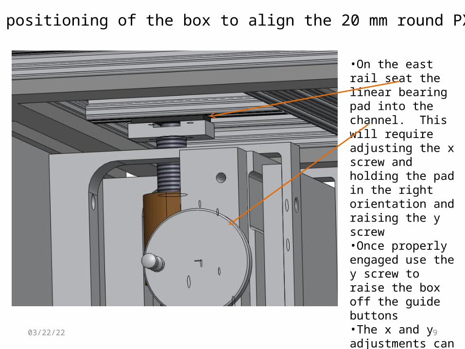
Fine positioning of the box to align the 20 mm round PXL rails
•On the east rail seat the linear bearing pad into the channel. This will require adjusting the x screw and holding the pad in the right orientation and raising the y screw•Once properly engaged use the y screw to raise the box off the guide buttons•The x and y adjustments can now be used to fine tune the box position

04/19/23 10
Alignment Requirements
• Collinearity• The rails in the box must be collinear with the rails in the MSC to allow
the carriage to transfer from one set of rails to the other with out binding.
L
Carriage support rails
Slider bearing

04/19/23 11
Alignment Requirements
• End to end alignment• The rails must but close enough end to end to allow the slider to pass
over the intersection
Carriage support rails
Slider bearing
2
In our case with = 100 m we have a 200 m tolerance assuming that the separation of the two rails are the same in the two systems.
This alignment gets forced by using tapered butt joints
The initial alignment has to be good to ~ 3 mm to engage the tapers. Bending the rails by 3 mm will not violate the collinearity condition.

04/19/23 12
Alignment measurement system
The above alignment monitor is used to determine the alignment of the two rail systems with respect to each other as the box support screws are adjusted. The system allows sequential independent setting of the 5 degrees freedom, i.e. the two angles of collinearity (x, y), x position, y position and z the angle about the z axis. This is accomplished with an auto collimation laser system plus two video cameras viewing survey targets. These parts are identified in the following slide. The two elements slide on the rails with spring loaded v blocks. The right element, LACW is located on the MSC support rails and the left element, LACE is located on the rails in the PXL transfer/storage box. The v blocks are tapered such that when the rails are aligned roughly by eye the right element can be slid across from the box rails to the MSC rails.
Laser Auto Collimator West(LACW)
Laser Auto Collimator East(LACE)
STARcoordinates
Y
XZ
ZYn
Ys
Xw
Xe
Y
y
zx
STAR coor. + rotations
Jack Screw identifications
East
North
WestSouth
Laser auto collimation figures from align_figure_instrument.SLDASM

04/19/23 13
Alignment measurement system, identification of parts
The above figure shows the two elements (LACW and LACE) mounted on a single set of rails. This the configuration for aligning the system prior to use.
cross hair diode laser
video cameras
laser pointing angle adjuster
laser auto collimator mirror
mirror angle adjuster
cross hair rotation adjuster
camera targets

04/19/23 14
Alignment InstructionsOutline of steps
Y
X Z
ZYn
Ys
Xw
Xe
Y
y
zx
STAR coor. + rotations
Jack Screw identifications
East
North
West
South
from align_box_support_fig.SLDASM
1. Zero the laser auto collimator2. Establish camera target match3. Adjust box into rough alignment by eye4. Adjust box into collinear alignment (x, y) with laser auto collimator5. Adjust box into x,y and z alignment using the laser cross hairs6. Adjust box into x, y and z alignment using cameras/survey targets7. Recheck collinearity8. Engage rails

04/19/23 15
1. Zero the laser auto collimator
a) Install the LACE and LACW on a set of calibration rails – could be the rails in the PXL storage box
b) Separate the two elements by 1 to 1.5 meters
To install
engage v block on lower rail
open spring loaded v block and engage on the upper rail and release
rotate safety latch into protect location – this still relies on spring load to engage the rail, but it prevents accidental derailment

04/19/23 16
1. Zero the laser auto collimator• Adjust laser pointing to center
on mirror• Adjust laser cross hair rotation
and secure with set screw• Adjust laser focus
center laser image on mirror center cross hairs
laser vertical and horizontal angle adjust
laser cross hair rotation
set screw to secure cross hair rotation
rotate to focus laser cross hairs

04/19/23 17
1. Zero the laser auto collimator
• Adjust mirror angle to center reflected laser cross hairs back on the out going laser beam image
mirror with adjustable mirror mount
reflected laser cross hairs
defocused image of out going laser on a frosted glass with a hole in the center
adjust mirror to center these two images

04/19/23 18
2. Establish Camera target match
• slide LACE and LACW together and back off to not quite touching
• connect target illuminators (USB powered LEDs in LACE)
• Bring up the two videocam views of the two survey targets and manual focus with the viewing software
• Mark screen with cross hairs centered on the target views
The measuring system is now calibrated and aligned ready for use.
survey targets
04/19/23 19
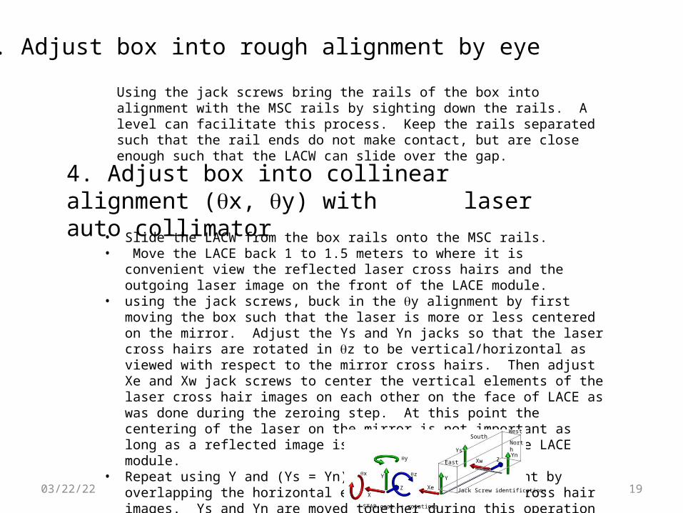
3. Adjust box into rough alignment by eye
Using the jack screws bring the rails of the box into alignment with the MSC rails by sighting down the rails. A level can facilitate this process. Keep the rails separated such that the rail ends do not make contact, but are close enough such that the LACW can slide over the gap.
4. Adjust box into collinear alignment (x, y) with laser auto collimator
• Slide the LACW from the box rails onto the MSC rails.• Move the LACE back 1 to 1.5 meters to where it is convenient view the reflected laser
cross hairs and the outgoing laser image on the front of the LACE module. • using the jack screws, buck in the y alignment by first moving the box such that the laser
is more or less centered on the mirror. Adjust the Ys and Yn jacks so that the laser cross hairs are rotated in z to be vertical/horizontal as viewed with respect to the mirror cross hairs. Then adjust Xe and Xw jack screws to center the vertical elements of the laser cross hair images on each other on the face of LACE as was done during the zeroing step. At this point the centering of the laser on the mirror is not important as long as a reflected image is maintained back at the LACE module.
• Repeat using Y and (Ys = Yn) to achieve x alignment by overlapping the horizontal elements of the laser cross hair images. Ys and Yn are moved together during this operation to maintain the z alignment.
Y
XZ
ZYn
Ys
Xw
Xe
Y
y
zx
STAR coor. + rotations
Jack Screw identifications
East
North
WestSouth
04/19/23 20
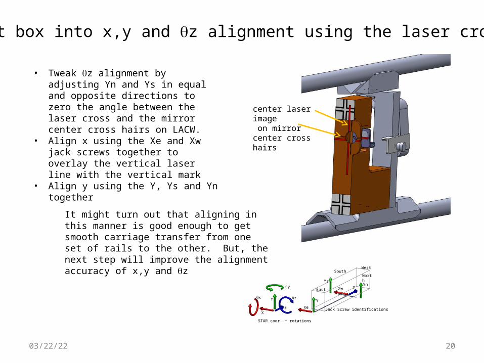
5. Adjust box into x,y and z alignment using the laser cross hairs
center laser image on mirror center cross hairs
• Tweak z alignment by adjusting Yn and Ys in equal and opposite directions to zero the angle between the laser cross and the mirror center cross hairs on LACW.
• Align x using the Xe and Xw jack screws together to overlay the vertical laser line with the vertical mark
• Align y using the Y, Ys and Yn together
It might turn out that aligning in this manner is good enough to get smooth carriage transfer from one set of rails to the other. But, the next step will improve the alignment accuracy of x,y and z
Y
XZ
ZYn
Ys
Xw
Xe
Y
y
zx
STAR coor. + rotations
Jack Screw identifications
East
North
WestSouth

04/19/23 21
6. Adjust box into x,y and z alignment using cameras/survey targets• Move LACE to almost touching LACW
and turn on LEDs and cameras• Use jack screws as in the previous
step to align the camera reference marks to the survey targets without disturbing the collinearity.
7. Recheck collinearity• Move LACE back 1 to 1.5 m and
recheck collinearity with the laser auto collimator
8. Engage rails• Using the Z jack screw butt the rails
so that the cone and sockets engage. Use care to avoid excessive force on the MSC rails.
Withdraw the LACW and remove and remove the LACE. The PXL can now be inserted.
Y
XZ
ZYn
Ys
Xw
Xe
Y
y
zx
STAR coor. + rotations
Jack Screw identifications
East
North
WestSouth