"swana 2012 excellence award application "landfill gas ... · swana 2012 excellence award...
TRANSCRIPT

1
SWANA 2012 EXCELLENCE AWARD
APPLICATION
“LANDFILL GAS CONTROL”
SENECA LANDFILL, INC
Thermal Oxidizer (Left) and Flare – Stack Testing

2

3
EXECUTIVE SUMMARY
Seneca Landfill Inc., has a commitment to energy independence and environmental protection
that is demonstrated by extensive projects to effectively collect and utilize Landfill Gas from
Seneca Landfill in a manner that provides an example of excellence for the Solid Waste Industry.
Seneca’s Landfill Gas Control Project attempts to recover every molecule of landfill gas for
productive use by the systems, equipment, techniques, training and operations described in this
application. In addition to the state of the art landfill gas collection equipment, the project
includes:
Combined Heat and Power Facility (CHP), provides electrical power for site use with
surplus power sold to the local electric utility, Penn Power. Cooling water is further
utilized to capture heat for site use.
LEGO-V, High Purity Gas Recovery Systems convert landfill gas to pipeline quality gas
sold to a local Gas Utility.
Features of Seneca’s Landfill Gas Control Project:
Constant monitoring,
Ongoing installation, relocation, and adjustment of wells for optimum gas collection,
Dedicated water removal systems,
Training and capability of staff, and
Attention to every possible source of landfill gas collection.
These features and activities Result in an exemplary, state of the art Landfill Gas Control Project
as described in this application.

4
DESIGN AND CONSTRUCTION
Siting, Preparation and Design:
Siting of the Seneca Landfill Gas Control Project was predicated by the existence of a
company owned and operated historic waste disposal facility that had been used for waste
disposal for almost forty years and was then generating significant quantities of landfill gas
which needed collected. Site Geology, Topography and historic use were evaluated and permit
application was made for a landfill that would exceed Subtitle “D” requirements on the existing
site. This construction included removal of some of the historic landfill. This action was
partially due to a commitment by the owners of Seneca Landfill to environmental protection and
partly due to the geometry the consolidated waste would achieve and the positive impact this
would have on collection of the landfill gas. Siting new facilities adjacent the existing structures
would produce the most cost effective and functional result with the least environmental and
community impact. Our regulators agreed, construction permits were issued and work
progressed through start up and enhancements are incorporated as technology develops. This
state of the art facility, evolving actively with developing technology, is also a research and
development site for new innovation. (See aerial of Project in Supporting Documents.)
Preparation and Design of the Seneca Landfill Gas Control Project initially was merely to
collect and destroy landfill gas from the existing site in a flare for environmental protection. The
owners of Seneca Landfill observed cost saving opportunity develop for landfill gas. The first
opportunity was to use the landfill gas for heat and electrical power. As landfill gas technology
evolved it became apparent that separation of the gas into methane and other gases would
strategically position Seneca Landfill for enhanced environmental controls and increase the
profitability of operations. Preparation included evaluating whether the volume of gas collected,
the avoided price for power purchased, the price for natural gas purchased, the value for
electricity generated and sold, the value of the methane sold, the cost of the systems and
operational cost of personnel to collect and process the landfill gas into energy could be
optimized to yield a favorable result.
Industry experience with electric generators powered by landfill gas demonstrated considerable
maintenance and operational costs from deposition of siloxanes, contained in landfill gas, in the
internal combustion engines. This very costly factor was removed when the technology to
separate methane from carbon dioxide and siloxanes became effective. Removing the high
maintenance and repair factors from the cost benefit evaluation favorably balanced the result.
The above factors resulted in formulation of the design basis of the Seneca Landfill Gas Control
Project, to achieve total collection of Landfill Gas – down to the last molecule – and to utilize
this resource for Seneca Landfill’s total energy independence. This design provides power for all
site operations and contributes to a profitable operation. This design basis also achieves odor
control, environmental protection, and fosters energy independence of the community we serve
and the solid waste industry by our example and performance in “state of the art” Landfill Gas
Control.

5
Blower, Flare, CHP and LEGO-V Design incorporated the NSPS requirements that LFG
control systems be designed such that they “Collect gas at a sufficient extraction rate (a rate
sufficient to maintain a negative pressure at all well heads in the collection system without
causing air infiltration, including any wellheads connected to the system as a result of expansion
or excess surface emissions, for the life of the blower).” The blower/flare equipment installed at
Seneca Landfill’s Gas Control Project was designed to handle the maximum gas flow rate
expected from the entire landfill, over the intended use period of the equipment. Therefore the
blower/flare was designed to handle at least 9,400 scfm of landfill gas. Ten inches of water
vacuum pressure at the well head located the furthest distance from the blower was specified in
design to assure in excess of ten inches of water vacuum at all other well heads in the system.
This specification resulted in a requirement of 9400 scfm at a minimum of 35 inches of water
inlet vacuum pressure.
The Seneca Landfill Gas Control Project installed one enclosed ZTOF flare with peripheral
equipment. Maximum capacity of this equipment is 6,000 SCFM of landfill gas. The unit is
manufactured by John Zink Company, LLC and was installed by the manufacturer and Seneca
Landfill employees. One direct drive, inlet driven, multistage blower sized for 6,000 SCFM of
landfill gas at 80 inches of water vacuum pressure at the inlet and 10 inch water column
completes the blower/flare installed equipment.
When the flare system described above reaches 80% of its design operational capacity, another
flare system rated at 5,000 SCFM of landfill gas is specified and will be installed.
CHP design provides the flexibility to operate directly on landfill gas, with the decision to incur
the additional maintenance and repair costs caused by siloxanes in raw landfill gas, or to utilize
either pipeline gas or methane gas purified by the LEGO-V system and avoid these costs. The
flexibility of the design enables the facility operators to evaluate prices for power, gas, and heat
against operational needs and energy sources available to make the most cost effective
operational decisions available based upon live time conditions. Typically the CHP would use
methane from the LEGO-V system and avoid the additional maintenance and repair expense
however, if the LEGO system is out of service, the pipeline gas is not available, there is no
outside power and the CHP is available, the CHP can operate on landfill gas and provide power
and heat to the entire site. The design truly provides the Seneca Landfill Gas Collection Project
a high degree of independence from outside power.
Research and Development continues in the removal of hydrogen sulfide from raw landfill gas to
further enhance the performance of the equipment and processes. Results of this research will be
shared with the solid waste industry when positive improvements are documented and approved
for market by the manufacturer.

6
Photo: CHP Building showing Jenbacher Landfill Gas Generator with Heat Recovery Piping
LEGO-V design introduced an entire “New World” of LFG control requirements as well as the
ability to produce pipeline quality methane gas which may be utilized for Seneca Landfill’s site
energy needs with the balance sold. The state of the art Pressure Swing Absorption and multi-
membrane gas separation technology is very sensitive to infiltration of Oxygen and Balance
Gases such as Nitrogen. With the Flare LFG could be destroyed with up to 5% Oxygen. With
the CHP technology the acceptable Oxygen level drops to 0.5%. With implementation of the
LEGO-V Project the acceptable levels of “contaminant gases” further reduced. The LFG
Control System was refined, the frequency of readings was increased, employees were trained to
operate gas analytical equipment, HDPE pipe fabrication and repair equipment and to monitor
and adjust the well field to maintain very tight parameters for the LEGO-V System and
compliance with the Operating Permits. As with the CHP, the operational flexibility to use the
flare remains. This option is rarely exercised as a LFG Control Device due to the environmental
and economic benefit of the state of the art enhancements to the Seneca Landfill LFG Control
Project.

7
Construction
Construction of the Seneca Landfill Gas Control Project is to New Source Performance
Standards (NSPS) described in 40 CFR 60 and started with the LFG Collection Wells and Flare.
The following performance limits were used to determine pipe sizes:
Velocity of the gas in the pipe will not exceed 100 feet per second.
Maximum allowable pressure drop within the pipe will not be greater than 1 inch water
column per 100 feet of pipe (0.036 psi/100 ft.).
Maximum pressure within the pipe will not exceed 25 psi.
Pipe diameters vary in size depending on the volume of LFG each pipe section is expected to
carry. Pipe sizing for the LFG collection system at Seneca Landfill was performed using Pipe-
Flo™ Fluid Flow Analysis Software using the following data:
Material: HDPE – Flexco
Schedule: 160 psi (SDR 11)
Fluid Zone: Methane
A model of the proposed Seneca Landfill LFG Control System was created in Pipe Flo™. The
input data for the LFG Control Project included:
LFG flow into the system at each proposed well head.
LFG flow into the system from the existing wells.
Pipe lengths, endpoint elevations, fittings and initial diameter.
Wellhead elevations.
Compressor inlet location and elevations.
Each section of pipe within the system was sized in accordance with the design criteria and
inputs described above. The Pipe-Flo™ software provided output data for each proposed section
of pipe within the system: gas flow volume (cfm), velocity (ft/sec), pressure loss[dP](psi),
length (ft), head loss [HL](ft) and resistance coefficient [k](unitless). The Pipe-Flo™ report also
provides flow rate (cfm), pressure loss (psi), and elevation date for each proposed node installed
along the LFG conveyance header pipe.
Connection of the Waste Water Treatment Plant to the cooling system of the CHP followed and
significant quantities of waste heat were recovered and used to replace fossil fuel consisting of
natural gas and/or propane gas for heating both the facility buildings and the waste water
processing equipment and tanks. This achievement successfully completed the CHP and Energy
Harvest Grant objectives to demonstrate that a clean-burning cogeneration project could use a
portion of the landfill gas to power the facility and to provide hot water for the leachate treatment
process and to operate continuously, in parallel, with the local electric utility company, Penn
Power, as a continuous “stand by” operation while providing environmental benefits which will
be discussed later.

8
Above: One of Two 600 HP Compressors in the LEGO-V System
Following completion of the Combined Heat and Power Project, Seneca Landfill’s owners
promptly moved to the next phase of the overall Landfill Gas Control Project with the design and
construction of the LEGO-V facility. LEGO-V is a “state of the art” Pressure Swing Absorption
(PSA) gas separation process which separates landfill gas through membranes, under pressure.
The membranes are supplied as a bank of individual membranes, by Air Liquide. (See Support
Documents.) The design allows change out of individual membranes or application of the desired
number of membranes for the quantity of gas available.
The membrane separation refines landfill gas into two components: Saleable, utility grade, high
purity methane gas and waste gas. The waste gas consists of carbon dioxide and balance gases.
Waste gases are destroyed in a Thermal Oxidizer.
The first 11 Landfill Gas Separation units deployed utilized high purity product gas as the energy
source to destroy the waste gases and any organic balance gases in the Thermal Oxidizer (TOX)
system. In the LEGO-V Project, the 12th unit sold in the US, advances in operating technology
developed by the owners of Seneca Landfill were adopted which utilized raw landfill gas to fuel
the TOX. This development resulted in a greater yield of pipe line quality methane from landfill

9
gas thereby further improving the technology of the already “state of the art system” and
improving the environmental and financial performance of this technology. This improvement
contributes to further marketing of “state of the art” technology which serves to provide
environment, solid waste industry and energy conservation benefits.
Photo Above: Air Liquide Gas Separator Membrane Skid – Right; PSA Beds on Left
during carbon change maintenance. Note activated carbon staged for recharging PSA
Beds in foreground.
The TOX is manufactured by Met-Pro Systems of Harleysville, PA. The LEGO-V unit features
a 48.5 inch inside diameter tube and is 40 feet high. The TOX processes up to 2010 scfm of PSA
waste gases at a nominal Higher Heating Value (HHV) of 95-120 Btu/cubic foot. The combined
burners are rated to burn a total of 3,000,000 Btu/hr of PSA Blowdown gases, 111 scfm, at 460-
600 Btu/cubic foot. At these heat contents, the maximum heat release in the TOX is rated at
14.47 million Btu/hr.
(See the Photograph of the Thermal Oxidizer on the Cover of this Document – Note that
the wiring exposed is test equipment for the Stack Testing Protocol in progress.)

10
Complete and thorough combustion and destruction of waste gases is accomplished by
deployment of burners fired by raw landfill gas in the base of the TOX. These burners operate
continuously and provide baseline heating of the chamber. Waste gases are introduced into a
“surge” tank with each blow down of the PSA beds. Gas from the surge tank is introduced into
the upper chamber of the TOX at a rate to achieve complete combustion of the waste gases
between blow down cycles of the PSA beds. The raw landfill gas provides the combustion
source for the combustible components of the waste gas and achieves total destruction of residual
methane and trace organic compounds. All flame is contained within the TOX and temperatures
are controlled via a PLC based temperature control loop that maintains a set temperature to the
TOX. The PLC is located in the control panel and is monitored remotely. The state of the art
control system features call out capabilities to notify the operators if attention is needed.
LEGO-V was designed to further utilize waste heat from the Waste Water Treatment Plant to
heat the facility by means of recirculating the discharge of the Waste Water Treatment Heat
Exchanger Fluids through a series of pipes embedded in the floor of the building. This final step
recovers the remaining heat energy from the Combined Heat and Power Project.
The LEGO-V project required two years from design to completion of construction in 2011. The
drive behind the project was to control methane from landfill gas, to prevent this contamination
from entering the environment, and to use this resource. Use included conserving (replacement
of) natural gas from wells and providing the option to power electrical generators without the
harmful siloxanes which plague operators of generators powered by landfill gas and to develop
an alternate fuel for Waste Collection Vehicles.
In advance of the LEGO-V project, the Combined Heat and Power Project (CHP) sought to
demonstrate that a clean-burning cogeneration (combined heat and power) project could use a
portion of landfill gas (LFG) at the Seneca Landfill and generate 335 KwH of electricity while
also providing hot water for the leachate treatment process. The electrical generation system
operates in parallel with the local electric utility company (Penn Power) and as a continuous
stand-by operation.
LEGO –V was brought on line in February, 2011 and is currently producing high purity methane
gas which is sold to Peoples Natural Gas Company through a gas transmission pipeline was
constructed to connect to the utility’s lines 1.99 miles from the site. Since start up, LEGO-V has
produced 290,000,000 cubic feet of pipe line quality gas, enough to provide for the annual needs
of 3,222 homes at 7.5 mCf/month from a resource which would have otherwise been destroyed
with no environmental or energy benefit. Overall, the Combined Heat and Power and the LEGO-
V Projects are believed to demonstrate one of the most effective and environmentally beneficial
“state of the art” Landfill Gas Control Projects in North America.
The result of the Seneca Landfill design and construction is a state of the art Landfill Gas
Control System that evolves with landfill construction, adoption of new technology and which
performs research and development to further enhance site and Solid Waste Industry
performance in landfill gas control.

11
Photo Above: Combined Heat and Power (Methane or LFG Powered Generator)
Control Panel
End Use Plans for the Seneca Landfill Gas Control Project include using the facility as a model
for others in the Solid Waste Industry, or in Secondary and College Level Education programs,
to provide a working, profitable, example of the application of state of the art technology in
Utilization of Landfill Gas to preserve energy independence in our operations, locally and
nationally. Seneca Valley High School is three miles south of Seneca Landfill and the
opportunity to provide educational programs for environmentally sound solid waste
management, power generation and conservation of resource through developing and applying
state of the art technology to Seneca Landfill’s Gas Utilization Project is an opportunity the
owners of Seneca Landfill welcome.
The design of the Seneca Landfill Gas Control Projecty provides for the beneficial elimination of
environmental contaminants now and well into the future. Use of the state of the are equipment
and facilities of the Seneca Landfill Gas Control Project during the operation of the facility and
through the Closure and Post Closure Phases of Seneca Landfill provide excellent environmental
protection and will continue to reduce environmental contamination from the use of other fossil
fuel through the end of active landfill gas production. Adoption of a second, larger, generator

12
may further allow the option of switching from production of pipe line gas to additional
electrical power generation to better serve the interests of the community and for enhanced
financial performance of the Project. Upon completion of active landfill gas production the
facilities and equipment may be dismantled and sold. The land area upon which they are
constructed may then be put to use for other beneficial purposes by the owners.
Photo Above: Landfill gas being collected from leachate piping clean out port in
capped landfill area.

13
ENVIRONMENTAL CONTROLS
Seneca Landfill’s Gas Control Project utilizes groundwater, landfill gas and leachate treatment
environmental controls as described below. Seneca Landfill utilizes a minimum, double, 60 mil
liner over a geo-composite liner to control leachate at the facility since 1993. Some cells have
double 80 mil liners and others have double geo-composite liners with 60 mil HDPE thicknesses
on each liner. As the facility undergoes expansion, Seneca Landfill is recovering historic waste -
emplaced without liners - voluntarily and moving this historic waste onto cells constructed with
the double 60 mil liners and geo-composite system to provide excellent environmental controls.
Groundwater - Since the landfill was initially constructed in 1961 there has been no groundwater
degradation. There are 12 groundwater monitoring wells that surround the landfill to
strategically monitor groundwater. One of the wells is an “up gradient” well that is used as a
reference for the remaining wells that are under or down gradient from the landfill in the ground
water flow pattern. These wells are sampled and tested quarterly. DEP is provided the results of
this sampling directly from the contracted Lab for their review. (Seneca Landfill and our host
Municipalities also receive a copy of the analytical results for review.
Seneca Landfill’s Gas Control system consists of 170 vertical wells, a gas collection system
powered by two 125 horsepower electric motors which serve to both collect the landfill gas and
to keep negative pressure on the landfill to prevent odor, a flare, the LEGO-V, and a Jenbacher
model JSG 208 generator set and control systems generate 335 kWh of power. The Jenbacher
unit consumes about 75 scfm of product gas from the LEGO-V facility rather than raw landfill
gas to prevent harm to the engine from siloxanes found in landfill gas which causes a mineral
deposit buildup on pistons and heads of internal combustion engines. Siloxanes in raw landfill
gas that are removed by the LEGO-V facility but the Jenbacher unit can also operate on the raw
landfill gas when the LEGO-V facility is not available. A 6,000 scfm Zink Flare is utilized to
destroy gas when the generator and the LEGO-V facilities are not available to productively use
the landfill gas. This condition is kept to a minimum. A separate air compressor powers
dedicated pneumatic gas well pumps which remove water from the landfill gas wells, maximize
the collection of landfill gas, and enhance the odor control capability of the system. In addition
to the vertical wells, Seneca Landfill’s LFG Control Project implements temporary horizontal
wells when other gas is found and collects LFG from pipe cleanouts to assure that every possible
molecule of LFG is controlled. (See photo on above page.)
The landfill gas collection wells are monitored and adjusted as necessary, often daily, to assure
proper function and compliance with operating permits.
Leachate is collected by a gravity flow collection system into a centralized pump station.
Secondary leachate collection is by the pneumatic pumps in the landfill gas collection wells.
Leachate from these wells is conveyed by a series of gas and leachate collection pipelines to the
leachate pump station where the leachate is separated and stored while the gas is directed to the

14
compressor which collects landfill gas for discharge to one of the three separate gas
control/processing facilities described above. From the leachate pump station, the leachate is
pumped into one of four, 400,000 gallon processing/ equalization or storage tanks. From there
leachate is processed through two clarifiers heated with heat recovered from the generator
powered by landfill gas, aerated to remove BOD then flocculent is added and the leachate is
processed through a filter press to remove suspended solids, heavy metals and other
contaminates. The leachate is then filtered and passed through a three tower aerobic bio-reactor
for ammonia removal. Chemistry is performed and composite samples taken. Upon review and
verification of the chemistry to permit conditions the leachate is discharged to Connoquenessing
Creek under Seneca Landfill’s NPDES permit.
Seneca Landfill’s Landfill Gas Control Project reduces greenhouse gas emissions and provides
benefits to the environment by eliminating 9,000 tons of methane emissions each year. By using
the hot water from the Jenbacher Generator Set, Seneca is using a valuable asset which would
otherwise be wasted. Generating both electricity and ‘natural’ gas from the decomposing
garbage in the landfill incorporates conservation into Seneca’s management plan. There is no
discharge of water from the use of the landfill gas. Leachate is separated from the gas and
processed separately. The cooling and heat transfer fluids are in closed loops and are
continuously recycled within the system. When periodic maintenance of the fluids is mandated,
the fluids are commercially recycled.
Off-site migration of subsurface gas must be minimized under NSPS. The LFG Control
System installed at Seneca Landfill is designed and constructed with environmental controls to
monitor and control subsurface gas migration in accordance with state and federal regulations.
The subsurface gas monitoring system is comprised of 27 monitoring probe clusters spaced
around the permit boundary. The monitoring probe clusters have shallow well depths of 0-25
feet, medium well depths of 25 to 45 feet and deep well depths, where applicable based upon
water table elevation, of 45-129 feet. These wells are monitored for Carbon Monoxide and
Methane.
Condensate removal from Seneca Landfill’s LFG Control Project has been designed based upon
9,238 scfm of landfill gas. Using the EPA Model the condensate design basis volume required
was 1,688,490 gallons per year, maximum, Condensate Generation. The condensate is collected
in the gas control system and separated from the gas at a “knock out” above the leachate
collection sump from whence it is pumped via double walled HDPE piping to the Waste Water
Treatment Plant for sampling and processing. Environmental Controls at the Seneca Landfill
Gas Control Project are state of the art and do an excellent job of protecting the environment in
our community.
15
REGULATORY COMPLIANCE
Vogel Holding Inc., owner of Seneca Landfill and the Landfill Gas Control Project, is a privately
held family business started in 1958 by Edward L. Vogel and Margaret J. Vogel, husband and
wife, which has grown into a successful enterprise with 451 employees. The employment
opportunity provides benefits to the local region. Vogel Holding is an Integrated Solid Waste
Management System committed to excellence in solid waste management in west central
Pennsylvania. Vogel Holding Inc., provides comprehensive services including: waste disposal,
recycling, processing of wood and shrubbery into mulch products, waste transportation, natural
gas production, electrical power generation, Christmas Tree recycling, and annual clean ups for
Host Municipalities.
Seneca Landfill provides educational opportunity for local students and organizations through
tours of the facility, presentations at Municipal functions, and support of environmental
education programs.
Edward R. Vogel, Vice President and Corporate Officer for Seneca Landfill, represents the
Private Sector on the DEP Solid Waste Advisory Committee and has served in this volunteer
position since 2005.
Seneca Landfill attempts to achieve full compliance with local, state and federal regulations
using the most up to date electronic monitoring systems, through training our staff and
compliance with our operating permits. The position of Seneca Landfill is that it is our duty to
operate in full compliance with all local, state and federal regulations and the operating permits
from DEP. It is our objective to foster an open and pro-active relationship with our regulators by
demonstrating our ongoing commitment to this duty.
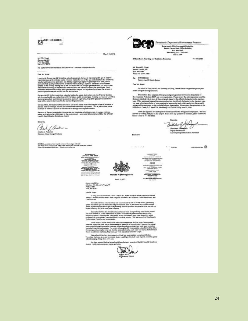
Cover pages from the Energy Harvest Grant Notification and Solid Waste Inspections are
enclosed with Supporting Documents. Due to space constraints the entire inspection reports
have not been submitted. There were no violations or items of non-compliance on the
inspection. Vogel Compliance Tracking Software allows our staff to monitor system compliance
from home or office and respond as necessary.
Seneca Landfill has an active safety program. The Landfill Gas Control Program has had no lost
time injuries or accidents. Safety Training in Accident Reduction Techniques (S.T.A.R.T) was
recently completed by all Seneca Managers and Supervisors.

16
PLANNING, OPERATIONS AND FINANCIAL
MANAGEMENT
The Seneca Landfill Gas Control Project created a unique, state of the art, set of equipment to
control Landfill Gas. Seneca Landfill has worked diligently to plan the facilities, equipment and
staff to operate an exemplary project with stringent environmental controls in a cost effective and
profitable manner. To this end Seneca Landfill has entered into contracts with two different
utilities to market both electricity and natural gas. This resulted in the flexibility to meet all
environmental concerns, provide for the energy needs of the site, and to selectively market
product to meet the most pressing energy needs of the community. (The most pressing needs are
also the most profitable market.)
The operating contracts provide a defined price for both electrical power and natural gas based
upon meter readings. Net Metering on the electric supply line provides for a backup power
supply In the event the Seneca Landfill power generator should fail while measuring power sold
when the generator is running. Under this concept if power going out exceeds power used,
Seneca Landfill is paid for the power generated per the terms of the contract. For the gas,
payment is based upon meter readings. There is no backflow capability on the gas line. Under
both contracts, Seneca Landfill is responsible for operating and maintaining the facilities which
produce the power or gas being marketed. While this project was envisioned as a way to reduce
the cost of energy consumed by Seneca Landfill and to demonstrate the benefits of co-generation
of clean power and heat, there is a potential for revenue from the Project as well as an
opportunity for positive public relations for the solid waste industry from public awareness of the
state of the art energy conservation systems being used at Seneca Landfill.
Capital expenditures and financial performance data for the Seneca Landfill Gas Control Project
is not available for publication, however the value of the electrical power and natural gas
produced may be readily computed from available references in the public domain. This will
allow planners to evaluate the cost benefit of a similar project at other facilities using site
specific cost and product sales values. Because the value of energy changes from minute to
minute in each market, the value of each commodity contemplated for market must be evaluated
in the local market then compared to the production technology contemplated.
The option to install a larger power generator within the current project boundaries to allow
focus of energy production on the product - power or gas - that will best serve the need of local
markets while simultaneously providing the most revenue to the owners of the project, provides
an opportunity for expansion of this project.

17
UTILIZATION OF EQUIPMENT/SYSTEMS AND
TECHNOLOGIES
Seneca Landfill’s Gas Control Project utilizes several components, described earlier:
Landfill Gas Control, Collection and Pre-Treatment, collects landfill gas and pre-
treats for use.
LEGO-V, the facility that produces high purity methane gas using state of the art
Pressure Swing Absorption Technology and Selective Membranes to yield high
purity, pipeline quality methane. This high purity methane is used to power the
HP or Combined Heat and Power component and sold as Natural Gas.
CHP provides electrical power for all site needs and heat for waste water
treatment and most buildings resulting in an operation that is energy independent
of outside power and natural gas. Both LEGO-V and CHP produce energy that is
sold to local utilities.
Heat Recovery System, provides heat to process equipment and facilities
eliminating the need to purchase natural gas for these purposes.
Aggressive control and collection of LFG to achieve profitable operations and
exemplary performance in landfill operations.
Vertical wells are equipped with dedicated, automatic, pneumatic well pumps to remove leachate
which reduces gas generation and collection efficiency. The leachate is pumped into the gas
collection headers and removed at a moisture separator near the leachate pump station where
leachate is collected in the sump for processing. The automatic, pneumatic, well pumps are
powered by a dedicated air compressor.
Processing of Landfill gas for production of high purity methane gas begins in the collection
lines where a proprietary chemical provided by Innospec and PPC Lubricants may be injected
into the 18 inch gas collection lines to precipitate hydrogen sulfides at the moisture separation
stage. Processing of the gas for production of methane continues with use of an optional Sulfa
Treat system to further reduce hydrogen sulfides which are harmful to the carbon filter beds in
the Pressure Swing Absorption system as needed. These state of the art options further improve
the effectiveness of the Seneca Landfill Gas Control Project and the Innospec/PPC technology is
unique to the industry.
LEGO-V receives the landfill gas collected. Using state of the art Pressure Swing Absorption
Technology and Selective Membranes provided by MEDAL and Air Liquide the process yields
high purity, pipeline quality methane. A fraction of this high purity methane is used to power the
CHP or Combined Heat and Power component and does not contribute to siloxane buildup on

18
the pistons and heads of the Jenbacher engine. The remaining high purity product gas is piped
1.99 miles to a gas transmission line and sold to Peoples Natural Gas Company (See Support
Documents). A meter at the tie in provides a record of the volume of gas sold. The gas is
monitored for BTU value, oxygen and nitrogen then an odorant is added by Seneca Staff.
Compliance tracking readouts are available on line. In the event of non-compliances Seneca
Staff is remotely notified and may adjust the system remotely to achieve compliance. Seneca
Staff are trained to operate and maintain the LEGO-V unit and have done so since start up.
Training is supplemented as innovation in systems develops new operating or maintenance
techniques.
CHP provides electrical power for all site needs utilizing a 335 kWh Jenbacher model JSG 238
generator set. Surplus power is sold to the local utility. Seneca Landfill Staff have been well
trained to operate and maintain this system well.
Heat Recovery System, provides heat to process equipment and facilities eliminating the need to
purchase natural gas for these purposes. Both LEGO-V and CHP produce energy that is sold to
local utilities thereby saving more than $30,000 per year in energy costs, conserving natural
resources and eliminating more than 9,000 tons/year of methane environmental pollution as well
as acid rain forming hydrogen sulfides.

19
PUBLIC ACCEPTANCE APPEARANCE AND
ASTHETICS
Photo Above: Welcome to Seneca Landfill
The Seneca Landfill Waste Utilization Project is kept neat and presentable. Daily inspections
and odor patrols are in place to ensure compliance with operating permits and minimal disruption
to our neighbors. Tours of the facility are available to those interested. In addition, Seneca Staff
visit the local municipalities and provide presentations on the activities and points of interest at
the facility.
At a recent Lancaster Township Meeting (Seneca Landfill’s Host Municipality) the Landfill Gas
Control, Landfill Reuse, and Landfill Gas Control Projects were described. Several members of
the audience commented: “I had no idea such a state of the art and comprehensive program
existed in our area.” (See letters from Lancaster and Jackson Township, Seneca Landfill’s Host
Municipalities, in the Support Documents Section)
Offering tours and sponsoring organized programs for Scouts and other civic groups helps foster
public acceptance. Seneca Landfill has approximately 600 acres of land providing opportunity

20
for many outdoor activities and environmental educational projects on the facility. These
projects are considered as requested in an attempt to foster community relations.
Seneca Landfill has been part of this community for more than 50 years and looks forward to
recognition for our efforts and continuing to provide a positive and proactive relationship with
our host municipalities, neighbors, the communities we serve and the Solid Waste Industry.
INNOVATION AND CREATIVITY
The Seneca Landfill Gas Control Project is the only facility in the world that currently utilizes
raw landfill gas to operate the Thermal Oxidizer and one of 15 facilities in North America that
use Pressure Swing Absorption and dual membrane technology to separate methane from landfill
gas and market it directly to a public utility.
Seneca Landfill’s Gas Utilization is unique in that it has the option to generate either electrical
power or gas to best meet the needs of the local market.
Seneca Landfill’s Gas Utilization Project is unique in having pre-treatment for removal of
hydrogen sulfide – the major component of acid rain – in our leachate and gas collection and
transmission lines as well as the option to utilize Sulfa Treat technology down-stream to further
reduce hydrogen sulfide contamination in our gas and leachate.
Secondary heat recovery is utilized to heat buildings from combustion of landfill gas in the CHP
facility.
Seneca Landfill’s Gas Utilization Project allows the facility to operate fully independent of
outside utilities for heat and power during normal operations and to provide backup energy
sources for our local community.
The Seneca Landfill Gas Control System evolves with adoption of new technology and performs
research and development to enhance site and industry performance in landfill gas control.
Seneca Landfill and our parent organization have a commitment to energy independence for our
facility, our community and our nation.
It is hoped the Seneca Landfill Gas Control Project is judged worthy of recognition for the
leadership in this area demonstrated by our employees and corporate management.

21
SUPPLEMENTAL MATERIALS
Most Recent DEP Inspection Report – No Items of Non-Compliance

22

23
24

25
Aerial View of Seneca Landfill Gas Control Project