synream. the synthes reaming systemsynthes.vo.llnwd.net/o16/llnwmb8/int mobile/synthes...
TRANSCRIPT

Surgical Technique
SynReam. The Synthes reaming system
This publication is not intended for distribution in the USA.
Instruments and implantsapproved by the AO Foundation.

Image intensifier control
This description alone does not provide sufficient background for direct use of DePuy Synthes products. Instruction by a surgeon experienced in handling these products is highly recommended.
Processing, Reprocessing, Care and MaintenanceFor general guidelines, function control and dismantling of multi-part instruments, as well as processing guidelines for implants, please contact your local sales representative or refer to:http://emea.depuysynthes.com/hcp/reprocessing-care-maintenanceFor general information about reprocessing, care and maintenance of Synthes reusable devices, instrument trays and cases, as well as processing of Synthes non-sterile implants, please consult the Important Information leaflet (SE_023827) or refer to: http://emea.depuysynthes.com/hcp/reprocessing-care-maintenance

SynReam Surgical Technique DePuy Synthes 1
Table of Contents
Standard instruments 2
Optional instruments 6
Surgical technique Reduction 8
Medullary reaming 10
Instruments 13
Optional instruments 14
Bibliography 16

2 DePuy Synthes SynReam Surgical Technique
Standard instruments
Flexible Shaft (352.040)The NITINOL shaft allows driving all reamer-head sizes with one shaft diameter only. Due to the closed cross section, the shaft can be used both clockwise and counter-clockwise. The front coupling has a hexagon for torsional transmission. In addition, the shaft is equipped with a click-on mechanism that primarily fixes the reamer heads onto the flexible shaft.
Pass the reaming rod through the shaft and reamer or reduc-tion head to ensure a secure, positive connection between both parts. The insertion of the reaming rod connects both parts firmly to one another.
Precaution: Never ream without using a reaming rod, as it secures the connection between the reamer head and the flexible shaft.
The coupling of the machine corresponds to that of the stan-dard system (large Synthes quick coupling) and allows cou-pling with the attachment for medullary reaming as well as with the angular drive. Use the individual reamer heads to ream in 0.5 mm incre-ments.
Reamer Heads (352.085–352.170)The chip spaces ensure facilitated chip flow. The 8.5 mm reamer head is equipped with front-cutting edges. For this reason, this diameter should be selected as the starting di-ameter. Reamer heads are available in diameters of 8.5 to 17 mm (in 0.5 mm increments).
Notes: – Inspect the reamer heads for damages, as blunt reamer
heads can increase intramedullary pressure and tempera-ture significantly14–15.
– For technical reasons (cutting geometry), the reamer heads cannot be resharpened. Damaged reamer heads have to be replaced.
14 Müller C.A., Mc Iff T., Rahn B.A., Pfister U., Weller S.: Intramedullary pressure, strain on the diaphysis and increase in cortical temperature when reaming the femoral medullary cavity – A comparison of blunt and sharp reamers. Injury 24, Suppl. 3: 22–30
15 Müller C.A., Rahn B.A., Pfister U., Weller S.: Extent of bluntness and damage to reamers from hospitals. Injury 24, Suppl. 3, 31–35
SynReam Surgical Technique DePuy Synthes 3
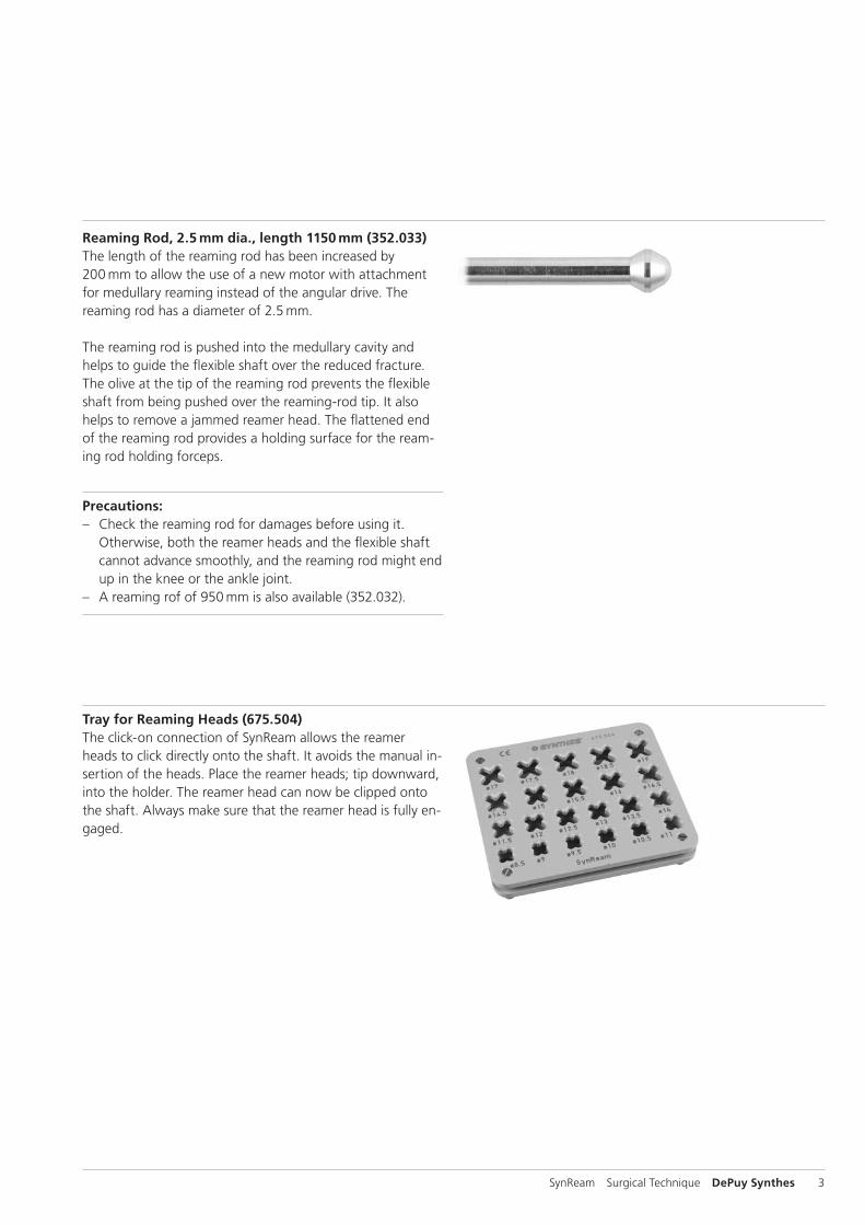
Reaming Rod, 2.5 mm dia., length 1150 mm (352.033)The length of the reaming rod has been increased by 200 mm to allow the use of a new motor with attachment for medullary reaming instead of the angular drive. The reaming rod has a diameter of 2.5 mm.
The reaming rod is pushed into the medullary cavity and helps to guide the flexible shaft over the reduced fracture. The olive at the tip of the reaming rod prevents the flexible shaft from being pushed over the reaming-rod tip. It also helps to remove a jammed reamer head. The flattened end of the reaming rod provides a holding surface for the ream-ing rod holding forceps.
Precautions: – Check the reaming rod for damages before using it.
Otherwise, both the reamer heads and the flexible shaft cannot advance smoothly, and the reaming rod might end up in the knee or the ankle joint.
– A reaming rof of 950 mm is also available (352.032).
Tray for Reaming Heads (675.504) The click-on connection of SynReam allows the reamer heads to click directly onto the shaft. It avoids the manual in-sertion of the heads. Place the reamer heads; tip downward, into the holder. The reamer head can now be clipped onto the shaft. Always make sure that the reamer head is fully en-gaged.

4 DePuy Synthes SynReam Surgical Technique
Removing Tool (351.783)A used reamer head can be removed from the flexible shaft without handling it. Keep the reaming rod in the medullar cavity and remove the shaft. Remove the used reamer head by pulling it through the recess of the removing tool.
Precaution: The reamer head can only be disengaged from the shaft if the reaming rod has been removed.
Reduction Head, straight (352.050)The straight reduction head helps to reduce the fracture.
Reduction Head, displacement 2.5 mm (352.055)The 2.5 mm displacement of the reduction-head tip helps to reduce displaced fragments.
T-Handle (351.150)Mounting the T-handle onto the shaft allows facilitated han-dling for reduction.
Standard instruments

SynReam Surgical Technique DePuy Synthes 5
Holding Forceps for Reaming Rods (351.782)The holding forceps for reaming rods combines three instru-ments of the current reaming system. It combines the func-tion of the following products:
391.880 Vice Grip
393.100 Universal Chuck with T-Handle
351.780 Holding Forceps
Handling
1. InsertionInsert the reaming rod into the medullary cavity using the holding forceps for reaming rods coupled parallel to the reaming rod.
2. HoldingFor reaming, use the holding forceps to hold the end of the reaming rod parallel or lengthwise. This prevents the with-drawal of the reaming rod when pulling the flexible shaft out of the medullary canal. Once the reamer head has been re-moved from the bone, the reaming rod can be grasped be-tween the reamer head and the canal entry point.
3. Emergency applicationShould a reamer head get jammed, use the holding forceps for reaming rods to take hold of the back end of the reaming rod, and remove the jammed reamer with light hammer blows on the holding forceps.
6 DePuy Synthes SynReam Surgical Technique
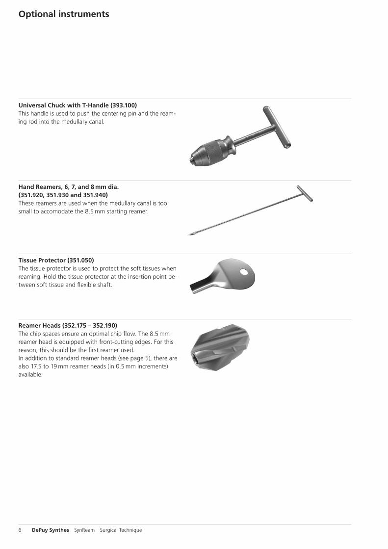
Universal Chuck with T-Handle (393.100)This handle is used to push the centering pin and the ream-ing rod into the medullary canal.
Hand Reamers, 6, 7, and 8 mm dia. (351.920, 351.930 and 351.940)These reamers are used when the medullary canal is too small to accomodate the 8.5 mm starting reamer.
Tissue Protector (351.050)The tissue protector is used to protect the soft tissues when reaming. Hold the tissue protector at the insertion point be-tween soft tissue and flexible shaft.
Reamer Heads (352.175 – 352.190) The chip spaces ensure an optimal chip flow. The 8.5 mm reamer head is equipped with front-cutting edges. For this reason, this should be the first reamer used. In addition to standard reamer heads (see page 5), there are also 17.5 to 19 mm reamer heads (in 0.5 mm increments) available.
Optional instruments

SynReam Surgical Technique DePuy Synthes 7
Air Jet to clean instruments (351.800)The air jet is made of synthetic material that cannot be steril-ized. It is used together with the air tube to clean the inside of the flexible shaft. It can be coupled to the compressed-air supply using an air hose with quick coupling. During the cleaning the flexible shaft needs to be fully submerged.Precaution: the Air Jet is intended for cleaning purposes only and may not be brought into the sterile field in the operating theater.
Air Tube, 2.0 mm dia. (351.810) for use with the air jetTo connect the tube to the air jet, remove the head of the air jet, push the tube through the head, and screw the head back onto the jet.
Cleaning Brush (352.041)Use this cleaning brush to clean the cannulation of the flexi-ble shaft. In case of an obstructed cannulation, use the reaming rod to push through it. The cleaning brush cannot be autoclaved.
Precaution: The Cleaning Brush is intended for cleaning purposes only and may not be brought into the sterile field in the operating theater.

351.150
352.050
352.040
352.055
8 DePuy Synthes SynReam Surgical Technique
The reduction aid can be used after opening of the medul-lary canal (see surgical technique of the corresponding im-plant system).
ReductionMount one of the Reduction Heads (352.050 or 352.055) and the T-Handle (351.150) onto the Flexible Shaft (352.040). For the fixation of the reduction head, insert the Reaming Rod (352.033 or 352.032) until the olive touches the reduc-tion head. During reduction, the reaming rod must be held in situ to ensure that it does not miss the displaced fragment.
Precaution: A secure fixation of the reduction head is not guaranteed if the reduction system is used without the reaming rod. The reduction head may be lost in the medul-lary canal.
Surgical technique
SynReam Surgical Technique DePuy Synthes 9
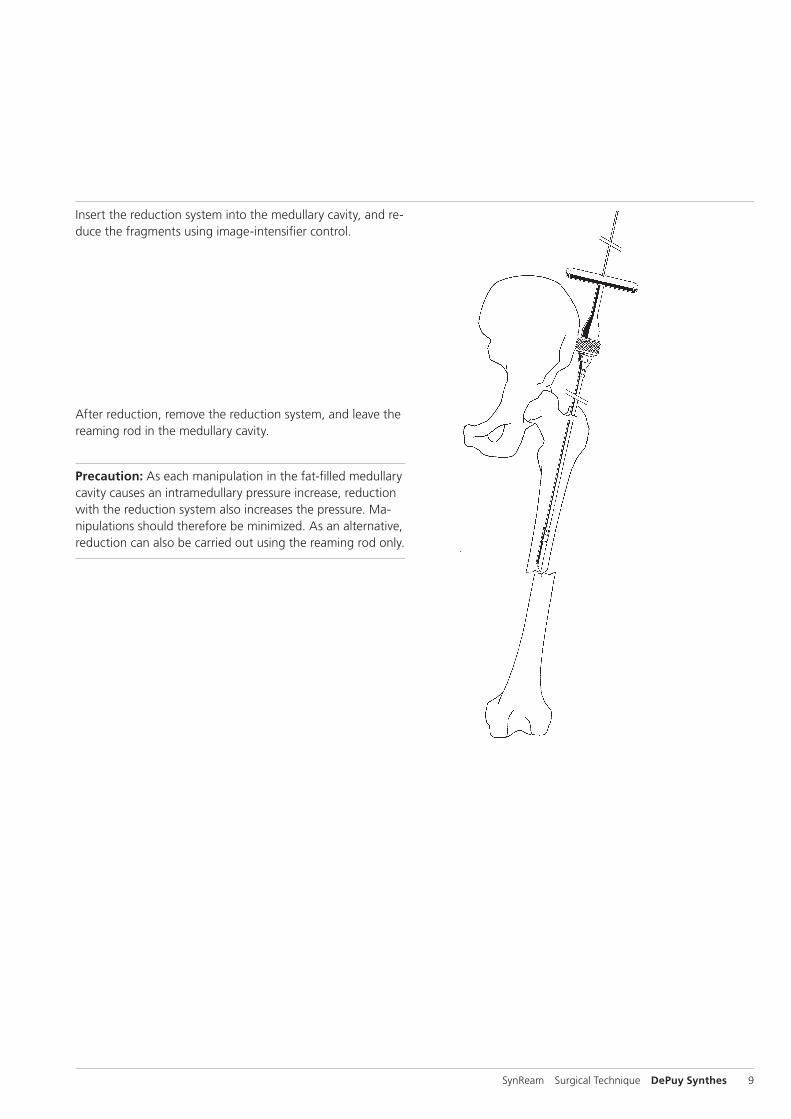
Insert the reduction system into the medullary cavity, and re-duce the fragments using image-intensifier control.
After reduction, remove the reduction system, and leave the reaming rod in the medullary cavity.
Precaution: As each manipulation in the fat-filled medullary cavity causes an intramedullary pressure increase, reduction with the reduction system also increases the pressure. Ma-nipulations should there fore be minimized. As an alternative, reduction can also be carried out using the reaming rod only.

10 DePuy Synthes SynReam Surgical Technique
Medullary reamingUse the Holding Forceps for Reaming Rods (351.782) or the Universal Chuck with T-Handle (393.100) to push the Ream-ing Rod (352.033 or 352.032) into the medullary canal.
Note: The reaming rod is already in the medullary canal, if the reduction has been achieved by means of the reduction system.
If the medullary canal is too narrow to pass with the reduc-tion tool start by opening with the hand reamer. Open the medullary canal up to 8.0 mm. 6.0 mm, 7.0 mm, and 8.0 mm Hand Reamers (351.920, 351.930 & 351.940) are available.Now the Reaming Rod (352.033 or 352.032) or the reduc-tion system can be pushed into the medullary cavity. Use the image intensifier to check the correct central position of the reaming rod in two planes.
Surgical technique

SynReam Surgical Technique DePuy Synthes 11
For the initial reaming, the flexible Shaft (352.040) is usually equipped with the 8.5 mm Reamer Head (352.085). Clip the shaft onto the reamer head in the Tray for Reaming Heads (675.504). If the click-on connection does not fit, turn the shaft slightly until the hexagon matches.
Precaution: This is only a primary connection. Always ream over the reaming rod to ensure a secure connection.
Connect the reamer with Attachment for Medullary Reaming (511.785) to a compatible power tool. Guide the reaming system over the reaming rod. Do not rotate the reamer head when inserting it into the medullary canal. The Tissue Protector (351.050) protects the soft tissues. Use the highest speed and slight but uniform force to advance the reamer head in the medullary canal. Move the reaming shaft backwards and forwards to remove the bone chips from the reamer head. This prevents jamming of the reamer head in the medullary cavity.
After full-length reaming of the medullary cavity, withdraw the ream ing shaft until the entire reamer head is visible. To prevent a loss of reduction, the assistant should grasp the reaming rod at the canal entry point, and hold the rod in place using the Holding Forceps for Reaming Rods (351.782).
If a reamer head gets jammed while reaming, disconnect the Attachment for Medullary Reaming (511.785). Mount the holding forceps onto the reaming rod (in the countersinking). Light hammer blows on the holding forceps allow drawing the jammed reamer head from the medullary canal using the reaming rod. As an alternative, release the reamer head by turning the shaft backwards.

12 DePuy Synthes SynReam Surgical Technique
A used reamer head can be removed from the flexible shaft without touching it, by pulling the reamer head through the recess of the Removing Tool (351.783).
Use sideways cutting reamer heads for the subsequent ream-ing steps. Use the click-on connection to click the next-in-size reamer head onto the shaft directly from the holder for reamer heads. This can be done without having to touch the reamer heads. Insert the reaming shaft and the reamer head over the reaming rod into medullary cavity. Reaming to the desired diameter is normally done in 0.5 mm increments.
Note: The subsequent surgical steps are carried out accord-ing to the corresponding surgical technique of the implant system used. In cannulated intramedullary nails, the nail can be inserted directly over the Reaming Rod (352.033 or 352.032) into the reamed me dullary cavity.
Precaution: Remove the reaming rod before locking the intra medullary nail.
Surgical technique

SynReam Surgical Technique DePuy Synthes 13
Instruments
352.033 Reaming Rod, 2.5 mm dia., L 1150 mm
352.040 Flexible Shaft
352.050 Reduction Head, straight
352.055 Reduction Head, displacement 2.5 mm
352.085 Reamer Head, 8.5 mm dia.
352.090 Reamer Head, 9.0 mm dia.
352.095 Reamer Head, 9.5 mm dia.
352.100 Reamer Head, 10.0 mm dia.
352.105 Reamer Head, 10.5 mm dia.
352.110 Reamer Head, 11.0 mm dia.
352.115 Reamer Head, 11.5 mm dia.
352.120 Reamer Head, 12.0 mm dia.
352.125 Reamer Head, 12.5 mm dia.
352.130 Reamer Head, 13.0 mm dia.
352.135 Reamer Head, 13.5 mm dia.
352.140 Reamer Head, 14.0 mm dia.
352.145 Reamer Head, 14.5 mm dia.
352.150 Reamer Head, 15.0 mm dia.
352.155 Reamer Head, 15.5 mm dia.
352.160 Reamer Head, 16.0 mm dia.
352.165 Reamer Head, 16.5 mm dia.
352.170 Reamer Head, 17.0 mm dia.

14 DePuy Synthes SynReam Surgical Technique
352.032 Reaming Rod, 2.5 mm dia., L 950 mm
351.020 Awl, small, L 210 mm
351.050 Tissue Protector, L 140 mm
351.060 Centering Pin, 4.0 mm dia., L 400 mm
351.240 Cutter, cannulated
351.260 Protection Sleeve for no. 351.240
351.800 Air Jet, not to be autoclaved
Optional instruments

SynReam Surgical Technique DePuy Synthes 15
351.810 Air Tube, 2.0 mm dia.
351.920 Hand Reamer, 6.0 mm dia.
351.930 Hand Reamer, 7.0 mm dia.
351.940 Hand Reamer, 8.0 mm dia.
352.041 Cleaning Brush for Flexible Shaft
352.175 Reamer Head, 17.5 mm dia.
352.180 Reamer Head, 18.0 mm dia.
352.185 Reamer Head, 18.5 mm dia.
352.190 Reamer Head, 19.0 mm dia.
393.100 Universal Chuck with T-Handle

16 DePuy Synthes SynReam Surgical Technique
Bhandari M., Guyatt G.H., Tong D., Adili A. & Shaughnessy S.G., Reamed versus non-reamed intramedullary nailing of lower extremity long bone fractures: a systematic overview and meta-analysis. J. Orthop. Trauma 14, 2 – 9 (2000).
Brumback R.J. & Virkus W.W., Intramedullary nailing of the femur: reamed versus non-reamed. J. Am. Acad. Orthop. Surg. 8, 83 – 90 (2000).
Chapman M.W., The effect of reamed and non-reamed in-tramedullary nailing on fracture healing. Clin. Orthop. S230 – S238 (1998).
Hupel T.M., Weinberg J.A., Aksenov S.A. & Schemitsch E.H., Effect of unreamed, limited reamed, and standard reamed intramedullary nailing on cortical bone porosity and new bone formation. J. Orthop. Trauma 15, 18 – 27 (2001).
Müller C.A., Schavan R., Frigg R., Perren S.M.:Intramedullary pressure increase for different commercial and experimental reaming systems: An experimental investi-gation J. of Orthop. Trauma 12, 540 – 546
Müller C. A., Baumgart F., Wahl D., Perren S. M., Pfister U.:Technical innovations in medullary reaming: Reamer design and intramedullary pressure increase.J. of Trauma, 49, 3, 440 – 445
Müller C. A., Frigg R., Pfister U.:Can modifications to reamer and flexible shaft design de-crease intramedullary pressure during reaming? An experi-mental investigation. Techniques in Orthopaedics, 11, 1, 18–27
Müller C. A., Frigg R., Pfister U.:Effect of flexible drive diameter and reamer design on the in-crease of pressure in the medullary cavity during reaming.Injury, 24, Suppl. 3: 40 – 47
Müller C.A., Mc Iff T., Rahn B.A., Pfister U., Weller S.:Intramedullary pressure, strain on the diaphysis and increase in cortical temperature when reaming the femoral medullary cavity – A comparison of blunt and sharp reamers.Injury 24, Suppl. 3: 22 – 30
Müller C.A., Rahn B.A., Pfister U., Weller S.:Extent of bluntness and damage to reamers from hospitals.Injury 24, Suppl. 3, 31 – 35
Pape N.C., Dwenger A., Grotz M., Kaever V., Negatsch R., Kleemann W., Regel G., Strum J.A., Tscherne H.:Does the reamer type influence the degree of lung dysfunc-tion after femoral nailing following severe trauma? An ani-mal study.J Orthop Trauma. 1994; 8; 4:300–309
Ryhäuen J., et al, Biocompatibility of nickel-titanium shape memory metal and its corrosion behavior in human cell cul-tures. J Biomed Mater Res, 35, 4, 1997.
Shabalovskaya S.A., On the nature of the biocompatibility and medical applications of NiTi shape memory and super-elastic alloys. Bio-Medical Materials and Engineering, 6, 4, 1996, 267 – 289.
Stuermer K.M., Schuchardt W.:Neue Aspekte der gedeckten Marknagelung und des Auf-bohrens der Markhöhle im Tierexperiment. II.: Der intramed-ulläre Druck beim Aufbohren der Markhöhle.Unfallheilkunde, 83, 1980.
Wenda K., Ritter G., Degreif J., Rudigier J.:Zur Genese pulmonaler Komplikationen nach Marknagelos-teosynthesen. Unfallchiurg, 91, 1988, 432 – 435
Wenda K., Henrichs K.J., Biegler J., Erbel R.:Nachweis von Markembolien während Oberschenkelmark-nagelungen mittels transoesophagealer Echokardiographie.Unfallchirurg, 15, 2, 1989, 73 – 76.
Bibliography


Synthes GmbHEimattstrasse 34436 OberdorfSwitzerlandTel: +41 61 965 61 11Fax: +41 61 965 66 00www.depuysynthes.com 0123 ©
DeP
uy S
ynth
es T
raum
a, a
div
isio
n of
Syn
thes
Gm
bH. 2
016.
A
ll rig
hts
rese
rved
. 03
6.0
00.
80
8 D
SEM
/TR
M/0
614/
0103
(1)
09/1
6
Not all products are currently available in all markets.
This publication is not intended for distribution in the USA.
All surgical techniques are available as PDF files at www.depuysynthes.com/ifu