synthesis and applications of dicationic iodide materials
TRANSCRIPT
J. Electrochem. Sci. Technol., 2019, 10(2), 214-222
− 214 −
Synthesis and Applications of Dicationic Iodide Materials for
Dye-Sensitized Solar Cells
Heejin Nam1,3, Yohan Ko2, Sakeerali C. Kunnan2, Nam-Soon Choi1, and Yongseok Jun2,3*1Interdisciplinary School of Green Energy, UNIST, 50 unist-gil Eonyang, Ulju, Ulsan, 44919, Korea2Department of Materials Chemistry and Engineering Konkuk University, 120 Neungdongro Gwangjin, Seoul, 05029, Korea3Department of Energy Engineering Konkuk University, 120 Neungdongro Gwangjin, Seoul, 05029, Korea
ABSTRACT
Dye-sensitized solar cells (DSSCs) have been receiving growing attentions as a potential alternative to order photovoltaic
devices due to their high efficiency and low manufacturing cost. DSSCs are composed of a photosensitizing dye adsorbed
on a mesoporous film of nanocrystalline TiO2 as a photoelectrode, an electrolyte containing triiodide/iodide redox couple,
and a platinized counter electrode. To improve photovoltaic properties of DSSCs, new dicationic salts based on ionic liquids
were synthesized. Quite comparable efficiencies were obtained from electrolytes with new dicationic iodide salts. The best
cell performance of 7.96% was obtained with dicationic salt of PBDMIDI.
Keywords : Dye-Sensitized Solar Cells, Dicationic Salts
Received : 13 December 2018, Accepted : 28 December 2018
1. Introduction
In the solar industry, now inorganic solid-state
junction devices are challenged by emergence of a
third generation of cell, based on nanocrystalline and
conducting polymers films. These offer the prospec-
tive of very low cost fabrication and present attrac-
tive features that facilitate market entry[1-4]. The
dye-sensitized solar cells (DSSCs), nanocrystalline
solar cells, have been regarded as one of the most
promising next-generation solar cells. DSSCs are
composed of various materials such as titanium diox-
ide (TiO2), dyes, redox couple electrolyte and trans-
parent conducting oxides. TiO2 is an n-type wide
band gap semiconductor, which is transparent for vis-
ible light. DSSCs convert visible light energy to elec-
trical energy through charge separation in sensitizer
dyes on a surface of TiO2.
The interception of the oxidized dye by the elec-
tron donor, normally I-, is in the microsecond time
domain. For a turnover number, that is, the cycle
life of the sensitizer in the DSSC device, to be
above, which is required for a DSSC lifetime of 20
years in outdoor conditions, the lifetime of the oxi-
dized dye must be >100 s if the regeneration time is
1 μs. This is achieved by the best-performing Ru
complexes.
The reduction of the oxidized sensitizer (S+) by
iodide follows most likely the following reaction
mechanism:
S+ + I- → (S· · ·I) (1)
(S· · ·I) + I- → (S· · ·I2-•) (2)
(S· · ·I2-•) → S + I2
-• (3)
2I2-• → I3
- + I- (4)
The first step is most likely a one-electron transfer
reaction between S+ and I-. The oxidation of iodide to
free iodine radical (I•) is, however, unlikely for ener-
getic reasons: U0(I•/I-) is +1.33 V vs. NHE in aqueous
solutions and has been reported to +1.23 V vs. NHE
in acetonitrile [5], which is more positive than the
U0(S+/S) of most of the dyes that are used as sensitiz-
Research Article
*E-mail address: [email protected]
DOI: https://doi.org/10.5229/JECST.2019.10.2.214
This is an open-access article distributed under the terms of the Creative CommonsAttribution Non-Commercial License (http://creativecommons.org/licenses/by-nc/4.0)which permits unrestricted non-commercial use, distribution, and reproduction in anymedium, provided the original work is properly cited.
Heejin Nam et al. / J. Electrochem. Sci. Technol., 2019, 10(2), 214-222 215
ers in DSCs. The redox potential of the iodine radical
bound to the dye (S · · · I) will be less positive in
potential, and the formation of a (S · · · I) complex
is therefore a likely first step in the dye regenera-
tion. Addition of a second iodide leads to the for-
mation of a (S · · · I2- •) complex, which can
dissociate into ground-state dye S and I2-•. Finally,
I2-• disproportionates under the formation of triio-
dide and iodide. The second-order rate constant for
this reaction is 2.3 × 10¹⁰ M-1s-1 in acetonitrile. Evi-
dence for the formation of intermediate dye-iodide
complexes comes from nanosecond laser spectros-
copy studies.
As shown above, iodide ions are playing very
important roles in turn over cycles[6-10], and their
structures also affect the whole device functions.
Herein, we suggest a newly synthesized types of
cations for iodide release, and applied to DSC sys-
tems.
2. Experimental
All chemicals and solvents used over the course of
this investigation were of reagent grade purchased
from Aldrich or Fluka, except 1-hexyl-2,3-dimethyl
imidazolium iodide(C-tri).
2.1 Synthesis of 3,3'-(pentane-1,5-diyl)bis(1,2-
dimethyl-1H-imidazol-3-ium) diiodide [PBDMIDI]
1,2-dimethyl imidazole (1.335 g, 13.88 mmol) and
1,5-diiodo pentane (1.500 g, 6.439 mmol) in 5mL of
toluene was heated to 110oC(reflux) for 12 h. The
solvent was removed by rotary evaporator. After this
step, white solid was obtained. For recrystallization
the white solid was dissolved in acetonitrile and then
added excess ethyl acetate. The mixture of products
and the solvent was filtrated. The filtrated material
was dried in a vacuum oven for 2 h. Finally, pure
white powders were obtained at yield of 96.2%
(2.3 g). The final product was confirmed with NMR.
1H NMR (D2O) (Fig. S1)
2.2 Synthesis of 3,3'-(2,2'-oxybis(ethane-2,1-
diyl))bis(1,2-dimethyl-1H-imidazol-3-ium) diio-
dide [EBDMIDI]
The same procedure was used, with 1.28 g
(13.8 mmol) of 1,2-dimethyl imidazole, and 1.45 g
(4.45 mmol) of 2-iodoethyl ether in 5mL of toluene.
2.18g, 94.6% yield. 1H NMR (D2O) (Fig. S2)
2.3 Synthesis of 1,1'-(pentane-1,5-diyl)bis(1-meth-
ylpyrrolidinium) diiodide [PBMPyDI]
The same procedure was used, with 1.11 g (13.0
mmol) of N-methylpyrrolidine, and 1.41 g (4.33
mmol) of 2-iodoethyl ether in 5mL of toluene. 2.05 g,
95.6% yield. 1H NMR (D2O) (Fig. S3)
2.4 Preparation of Electrolytes
1-hexyl-2,3-dimethyl imidazolium iodide (HDMII)
was used to prepare the reference electrolyte. 0.6 M
1-hexyl-2,3-dimethyl imidazolium iodide (HDMII),
0.1 M lithium iodide (LiI), 0.05 M iodine (I2), 0.1 M
guanidinium thiocyanate and 0.5 M tert-butyl pyri-
dine (TBP) dissolved in acetonitrile and mixture of
acetonitrile, propylene carbonate, ethylene carbonate
and γ-Butyrolactone. In order to investigate the dif-
ferent kinds of dicationic iodide on photovoltaic per-
formance three different iodide electrolytes prepared
by using 0.3 M PBMIDI, EBDMIDI and PBMPyDI
with same composition of reference electrolyte
instead of HDMII.
2.5 Ionic Conductivity
Ionic conductivity of the electrolytes was deter-
mined by the electrochemical impedance spectros-
copy m ethod. Elec t rochem ica l im pedance
spectroscopy (EIS) measurement was carried out
with CHI 660C. The frequency range in EIS mea-
surement was 0.05-105 Hz. The magnitude of the
alternative signal was 10 mV, and the applied bias is
0 V. Conductivity of a liquid was measured from the
obtained solution resistance or bulk resistance, fol-
lowed equation:
σ = l/(Rs × A) (5)
where σ is the conductivity (Ω-1 cm-1 or S cm-1), l is
the distance between two electrodes, which is the
thickness of the solution (cm), A is the electrode area
(cm2), and Rs is the bulk resistance (Ω).
2.6 Fabrication of Dye-sensitized Solar Cells
Preparation of TiO2 photoelectrodes were made
following steps. The TiO2 paste (20 nm TiO2, ENB
korea) was deposited on the conducting glass with a
fluorine-doped tin oxide layer (FTO, TEC 8/2.3 mm,
Pilkington) by doctor blade method. After depositing
of 20 nm particle size TiO2 paste, 200 nm TiO2 scat-
tering paste put on the top of previous layer. Working

216 Heejin Nam et al. / J. Electrochem. Sci. Technol., 2019, 10(2), 214-222
electrodes were sintered at 500oC in a muffle furnace.
Dye absorption was carried out 0.3 mM tert-butanol/
acetonitrile (1:1, v/v) solution of the ruthenium dye,
N719 (eversolar). Counter electrodes were prepared
by thermal reduction of chloroplantinic acid hexahy-
drate 10 mM in 2-propanol. This solution dropped on
FTO glass with a hole and drop casted electrodes
annealed at 450oC. The counter electrodes were
assembled with dye-coated working electrodes like
sandwich. Two electrodes were separated by 50 μm
thick thermoplastic polymer film Surlyn and sealed
by heating. The internal space was filled with electro-
lyte by vacuum. Finally, the hole was sealed with
peace of Surlyn and cover glass.
2.7 Photovoltaic Characterization
Measurements were carried out with the solar cells
by using a high quality optical fiber to guide the light
from the solar simulator equipped with a Keithley
2635A source measurement unit. The current-voltage
(I-V) curves were recorded on the equipment. The
photocurrent was measured under simulated
AM1.5G irradiation (100 mW cm-2), using a xenon
lamp-based solar simulator. The fill factor (FF) was
calculated by FF = (VmaxJmax)/(JscVoc), where Vmax and
Jmax are the voltage and the current density in the
maximum power point of the I-V curve in the fourth
quadrant. The normal power conversion efficiency
was calculated from the expression.
PCE=FF × Isc (mA cm-2) × Voc(V) ⁄ Pin (mW cm-2) (6)
where Voc, Isc, FF, and Pin are the open circuit volt-
age, short circuit current, FF, and incident light
power, respectively
3. Results and Discussion
3.1 Dicationic Salts in Acetonitrile
There are ionic salts for the experiment with detail
structure and full names (Table 1). 1-hexyl-2,3-
dimethyl imidazolium iodide (HDMII) was used to
prepare the reference electrolyte. 0.6 M 1-hexyl-2,3-
dimethyl imidazolium iodide (HDMII), 0.1 M lith-
ium iodide (LiI), 0.05 M iodine (I2), 0.1 M guanidin-
ium thiocyanate and 0.5 M tert-butyl pyridine (TBP)
dissolved in acetonitrile. However, synthesized ionic
salts are used half amount of HDMII, 0.3 M concen-
trations, the other electrolytes compositions are the
same of reference electrolyte. Their ionic conductivi-
ties are very different depending on ionic salts, from
0.08~38.68 mS cm-1. These differences of electrolyte
Table 1. Ionic salts for the experiment and their abbreviations
Ionic salt Abbreviation Chemical Structure
1-hexyl-2,3-dimethyl imidazolium iodide HDMII
3,3'-(pentane-1,5-diyl)bis(1,2-dimethyl-1H-
imidazol-3-ium) diiodidePBDMIDI
3,3'-(2,2'-oxybis(ethane-2,1-diyl))bis(1,2-
dimethyl-1H-imidazol-3-ium) diiodideEBDMIDI
1,1'-(pentane-1,5-diyl)bis(1-methylpyrrolidin-
ium) diiodidePBMPyDI
N+
N
I-
N N+
N+
N
I- I-
N N+
O
N+
N
I- I-
N+
N+
I - I-
Heejin Nam et al. / J. Electrochem. Sci. Technol., 2019, 10(2), 214-222 217
ion conductivity came from solubility difference in
acetonitrile. Especially EBDMIDI and PBMPyDI
have very poor solubility in acetonitrile. PBDMIDI
electrolyte is better soluble than other synthesized
ionic salts. In this reason, PBDMIDI electrolyte
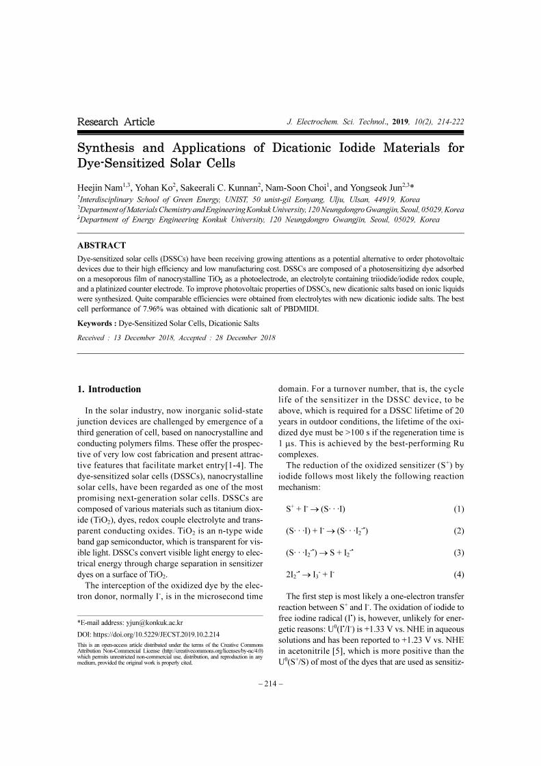
showed the best efficiency among electrolytes. Fig. 1
and Table 2 show J-V characteristics of the cells with
each electrolyte, photovoltaic parameters, respec-
tively. The Jsc ranges from 14.7 mA cm-2 to 15.7 mA
cm-2. PBDMIDI has the highest Jsc value, and PBD-
MID cell showed the best efficiency.
Quite comparable efficiencies were obtained from
electrolytes with synthesiszed dicationic iodide salts.
Bulky cation, EBDMIDI, shows higher Voc than
HDMII.
3.2 Dicationic Salts in Mixture of Acetonitrile
(AcCN) and Propylene Carbonate (PC).
Synthesized dicationic salts did not well dissolve in
acetonitrile. Dicationic salts might have stronger
ionic bond than HDMII, therefore, these salts may
need strong polar solvent. Propylene carbonate (PC)
is an organic compound which is useful as a high
polar solvent. Like previous experiment, 1-hexyl-2,3-
dimethyl imidazolium iodide (HDMII) was used to
prepare the reference electrolyte. 0.6 M 1-hexyl-2,3-
dimethyl imidazolium iodide (HDMII), 0.1 M lith-
ium iodide (LiI), 0.05 M iodine (I2), 0.1 M guanidin-
ium thiocyanate and 0.5 M tert-butyl pyridine (TBP)
dissolved in acetonitrile. However, synthesized ionic
salts are used half amount of HDMII, 0.3 M concen-
trations, the other electrolytes compositions are the
same of reference electrolyte. Acetonitrile and pro-
pylene carbonate solvent ratios were controlled. The
Acetonitrile:PC solvents were mixed with different
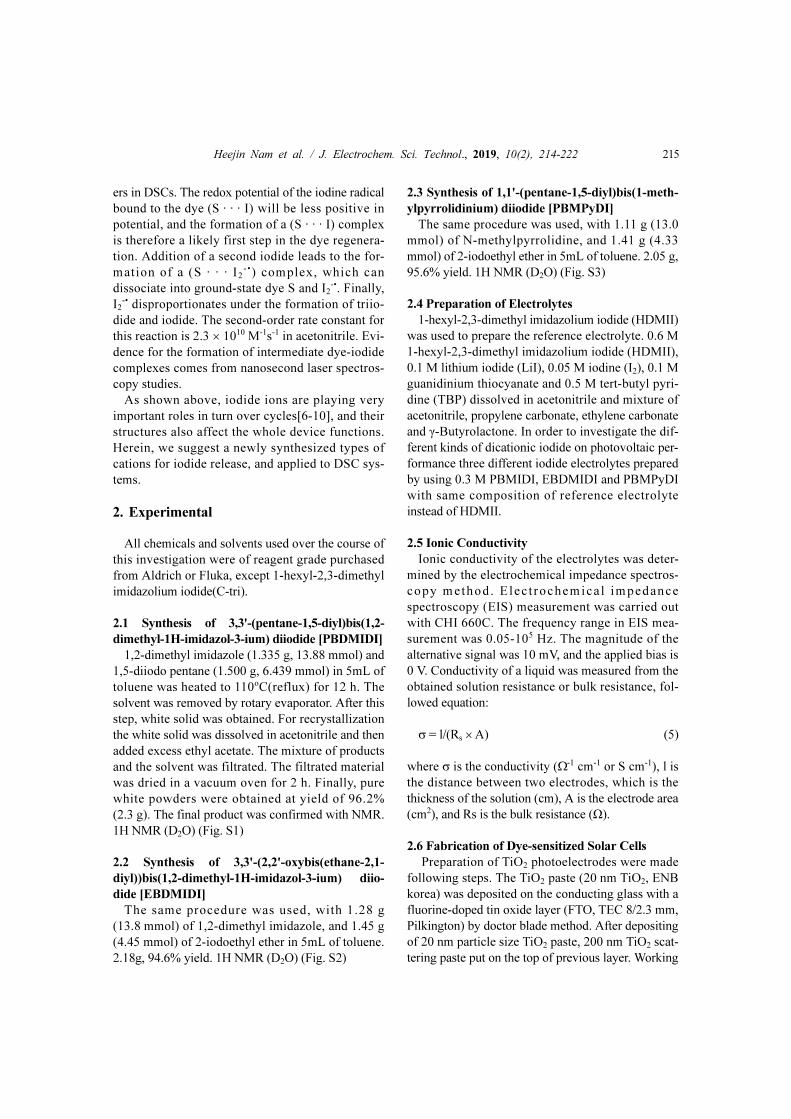
ratios, 7:3, 5:5, 3:7 and 0:1 (v/v). Fig. 2 and Table 3
show J-V characteristics of the cells with each elec-
trolyte, photovoltaic parameters, respectively. In case
of HDMII, HDMII with 7:3 (AcCN:PC) volume ratio
solvent has the best efficiency compared with other
ratios, but it did not reach the efficiency of the cell
with only acetonitrile solvent. There is a rough ten-
dency. When PC ratio increasing, the series resis-
tance was also increased. The increased series
resistance caused a low FFs. Therefore, the higher
concentrations of PC there are, the poorer efficiencies
were observed. The reason why higher concentration
of PC solvent has poor efficiency is due to high vis-
cosity of PC. Except PBPyDI, in most cases synthe-
sized materials have higher Voc than HDMII. Owing
to the existence of bulky dications on TiO2 photo-
electrode surface, these bulky dications prohibited
Li+ ion from affecting on conduction band of TiO2.
Dicationic salts are available on the surface, occupy a
much larger area than Li+ ions. Therefore, bulker cat-
ions on the TiO2 surface relieved lowering of the con-
duction band edge by Li+ ions [11].
When 7:3 (AcCN:PC) volume ratio solvent was
Table 2. Electrolyte ionic conductivity and photovoltaic parameters of the devices different salts dissolved in acetonitrile
Ionic saltIonic conductivity
[mS cm-1]
Jsc
[mA cm-2]
Voc
[V]
FF
[%]
PCE
[%]
HDMII 2.30 15.4 0.724 67.6 7.53
PBDMIDI 0.08 15.7 0.724 68.4 7.76
EBDMIDI 38.68 15.1 0.739 65.2 7.28
PBMPyDI 26.95 14.7 0.684 68.8 6.90
Fig. 1. Current density-voltage (J-V) characteristics of the
each devices with different ionic salt in acetonitrile HDMII
(), PBDMIDI (), EBDMIDI (), PBPyDI ()
measured under AM1.5G illumination from a calibrated
solar simulator with irradiation intensity of 100 mW cm-2

218 Heejin Nam et al. / J. Electrochem. Sci. Technol., 2019, 10(2), 214-222
Fig. 2. Current density-voltage (J-V) characteristics of the each devices with different ionic salt HDMII (), PBDMIDI (),
EBDMIDI (), PBPyDI () with different ratios of solvent (a) AcCN:PC=7:3, (b) AcCN:PC=5:5, (c) AcCN:PC=3:7, (d)
PC, (v/v) measured under AM1.5G illumination from a calibrated solar simulator with irradiation intensity of 100 mW cm-2
Table 3. Photovoltaic parameters of the devices different salts dissolved in different acetonitrile (AcCN):propylene
carbonate (PC) volume ratios.
(a)
AcCN:PC=7:3Jsc
[mA cm-2]
Voc
[V]
FF
[%]
PCE
[%]
Shunt resistance
[kΩ]
Series resistance
[Ω]
HDMII 16.2 0.729 63.7 7.51 5.01 37.25
PBDMIDI 16.0 0.739 61.0 6.91 1.96 39.74
EBDMIDI 15.5 0.729 65.3 7.37 5.59 34.31
PBMPyDI 15.7 0.709 60.3 6.71 2.79 48.39
(b)
AcCN:PC=5:5Jsc
[mA cm-2]
Voc
[V]
FF
[%]
PCE
[%]
Shunt resistance
[kΩ]
Series resistance
[Ω]
HDMII 16.4 0.729 54.8 6.55 5.39 50.64
PBDMIDI 16.0 0.754 57.2 6.88 12.38 48.34
EBDMIDI 16.1 0.754 57.0 6.93 12.08 58.61
PBMPyDI 16.1 0.724 59.0 6.82 26.64 46.89

Heejin Nam et al. / J. Electrochem. Sci. Technol., 2019, 10(2), 214-222 219
used, PBDMIDI electrolyte has the efficiency among
different solvents with a good FF. Likewise, EBD-
MIDI and PBPyDI electrolytes were observed simi-
lar tendencies. While PC concentration was
increasing, synthesized materials well dissolved,
which did not have connection between solubility
and efficiency. Increasing PC concentration, one of
photovoltaic device characteristics, Jsc and FF were
dropped. Both Jsc and FF are influenced by the ionic
conductivity of electrolyte, because low conductivity
causes rate determining of charge transportation and
increasing the series resistance [12]. Ionic conductiv-
ity directly related by viscosity of electrolyte [13].
3.3 Dicationic Salts in Mixture of Acetonitrile
(AcCN) and Ethylene Carbonate (EC).
Synthesized dicationic salts did not well dissolve in
acetonitrile. Because dicationic salts may have stron-
ger ionic bond than HDMII, these salts may need
strong polar solvent. Ethylene carbonate (EC) is used
as a polar solvent with a molecular dipole moment of
4.9 D [14], only 0.1 D lower than that of propylene
carbonate. Like previous experiment, 1-hexyl-2,3-
dimethyl imidazolium iodide (HDMII) was used to
prepare the reference electrolyte. 0.6 M 1-hexyl-2,3-
dimethyl imidazolium iodide (HDMII), 0.1 M lith-
ium iodide (LiI), 0.05 M iodine (I2), 0.1 M guanidin-
ium thiocyanate and 0.5 M tert-butyl pyridine (TBP)
dissolved in various ratio of solvents. However, syn-
thesized ionic salts are used half amount of HDMII,
0.3 M concentrations, the other electrolytes composi-
tions are the same of reference electrolyte. Acetoni-
trile and propylene carbonate solvent ratios were
controlled. The Acetonitrile:EC solvents were mixed
with different ratios, 1:0, 7:3, 5:5 and 3:7 (v/v).
(c)
AcCN:PC=3:7Jsc
[mA cm-2]
Voc
[V]
FF
[%]
PCE
[%]
Shunt resistance
[kΩ]
Series resistance
[Ω]
HDMII 16.0 0.724 56.3 6.61 21.13 48.20
PBDMIDI 15.7 0.734 54.1 6.24 0.86 46.75
EBDMIDI 15.7 0.734 57.1 6.57 33.45 52.99
PBMPyDI 15.2 0.704 60.7 6.49 2.69 46.38
(d)
PCJsc
[mA cm-2]
Voc
[V]
FF
[%]
PCE
[%]
Shunt resistance
[kΩ]
Series resistance
[Ω]
HDMII 14.2 0.729 50.1 5.18 13.10 64.82
PBDMIDI 13.5 0.734 51.9 5.12 18.6 65.08
EBDMIDI 13.3 0.734 54.2 5.27 12.21 59.63
PBMPyDI 12.8 0.709 52.2 4.75 2.97 76.26
Table 4. Photovoltaic parameters of the devices different
salts dissolved in different acetonitrile (AcCN):propylene
carbonate (EC) volume ratios
(a)
AcCN:EC=7:3Jsc
[mA cm-2]
Voc
[V]
FF
[%]
PCE
[%]
HDMII 15.9 0.734 63.1 7.35
PBDMIDI 15.8 0.744 67.7 7.96
EBDMIDI 15.8 0.729 67.4 7.66
PBMPyDI 15.6 0.719 67.3 7.53
(b)
AcCN:EC=5:5Jsc
[mA cm-2]
Voc
[V]
FF
[%]
PCE
[%]
HDMII 15.2 0.739 61.9 6.96
PBDMIDI 15.7 0.749 61.2 7.21
EBDMIDI 15.2 0.744 65.5 7.37
PBMPyDI 15.1 0.734 64.8 7.18
(c)
AcCN:EC=3:7Jsc
[mA cm-2]
Voc
[V]
FF
[%]
PCE
[%]
HDMII 15.0 0.749 57.4 6.46
PBDMIDI 15.4 0.754 59.1 6.87
EBDMIDI 15.3 0.749 60.0 6.85
PBMPyDI 15.2 0.729 60.7 6.72
220 Heejin Nam et al. / J. Electrochem. Sci. Technol., 2019, 10(2), 214-222
Because the melting point of ethylene carbonate is
higher than room temperature, EC based solvent
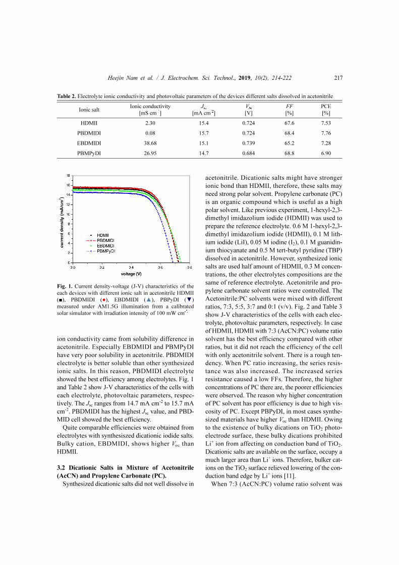
electrolyte wasn’t carried out. Fig. 3 and Table 4
show J-V characteristics of the cells with each elec-
trolyte, photovoltaic parameters, respectively. Instead
of using PC on electrolyte, Jsc did not observe signifi-
cantly. PBDMIDI electrolyte had the highest effi-
ciency in every composition of AcCN and EC
mixture. The reason why PBDMIDI electrolyte cells
have higher efficiencies than others is PBDMIDI
electrolyte cells have slightly higher voltages and FFs
than others. In case of EC, also except PBPyDI, syn-
thesized dication salt electrolytes have higher Voc than
HDMII. The reason is the same effect of bulky cation
on TiO2 surface [11].
3.4 Dicationic Salts in Mixture of γ-Butyrolactone
and Ethylene Carbonate.
In addition, mixed solvent of ethylene carbonate
(EC) and γ-Butyrolactone (GBL) is used for high
temperature stable electrolyte system. The boiling
point of EC is 248oC. γ-Butyrolactone (GBL) is also
a good candidate for solvent due to its high boiling
point of 204oC. In addition, its dielectric constant of
42 and low viscosity of 1.7 mPas-1 are preferable
characteristics for DSSC applications. A mixture of
EC + GBL (30:70, v/v, chosen based on the phase
diagram) has been employed as a stable solvent at
high temperatures [15,16]. Like previous experiment,
1-hexyl-2,3-dimethyl imidazolium iodide (HDMII)
was used to prepare the reference electrolyte. 0.6 M
Fig. 3. Current density-voltage (J-V) characteristics of the
each devices with different ionic salt HDMII (),
PBDMIDI (), EBDMIDI (), PBPyDI () with
different ratios of solvent (a) AcCN:EC=7:3, (b)
AcCN:EC=5:5, (c) AcCN:EC=3:7 (v/v), measured under
AM1.5G illumination from a calibrated solar simulator
with irradiation intensity of 100 mW cm-2
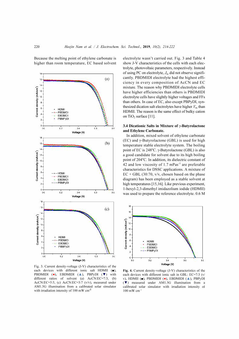
Fig. 4. Current density-voltage (J-V) characteristics of the
each devices with different ionic salt in GBL: EC=7:3 (v/
v), HDMII (), PBDMIDI (), EBDMIDI (), PBPyDI
() measured under AM1.5G illumination from a
calibrated solar simulator with irradiation intensity of
100 mW cm-2

Heejin Nam et al. / J. Electrochem. Sci. Technol., 2019, 10(2), 214-222 221
1-hexyl-2,3-dimethyl imidazolium iodide (HDMII),
0.1 M lithium iodide (LiI), 0.05 M iodine (I2), 0.1 M
guanidinium thiocyanate and 0.5 M tert-butyl pyri-
dine (TBP) dissolved in EC + GBL (30:70, v/v).
However, synthesized ionic salts are used half
amount of HDMII, 0.3 M concentrations, the other
electrolytes compositions are the same of reference
electrolyte. Fig. 4 and Table 5 show J-V characteris-
tics of the cells with each electrolyte, photovoltaic
parameters, respectively. In this experiment, there are
little different in Jsc and Voc. However, dicationic salts
have better FFs than HDMII. It caused higher effi-
ciencies. The best performance among them is EBD-
MIDI electrolyte which is 6.022% with 14.8 mA cm-2
(Jsc), 0.719 V (Voc) and 56.7% (FF).
4. Conclusions
DSSCs are recognized as the promising device in
the solar industry. These offer the prospective of very
low-cost fabrication and present attractive features
that facilitate market. In this work, it has been inves-
tigated to improve photovoltaic properties of DSSCs.
New dicationic salts-based on ionic liquids were syn-
thesized. Synthesized bulky cationic salts have been
used in DSSC electrolyte systems as iodide sources
with various solvent (mixture of acetonitrile, ethylene
carbonate, propylene carbonate and γ-butyrolactone)
systems. In this case, quite comparable results to the
conventional imidazolium salts are obtained. For the
experiments, dicationic salts with different structures
of cation are applied. Possible reasons are suggested
for Voc changes, Jsc drops and FF depending on com-
position of electrolyte solvent. Future directions of
dicationic iodides should not only find better mole-
cules than generally used one but also need to investi-
gate mechanisms of dications behavior in the
electrolyte. They are quite comparable to conven-
tional mono-cationic device efficiencies with best
efficiency of 7.96% with PBDMIDI.
Acknowledgement
This paper was supported by Konkuk University
Researcher Fund in 2017. This work is supported by
the Korea Institute of Energy Technology Evaluation
and Planning (KETEP) and the Ministry of Trade,
Industry and Energy (MOTIE, 20174010201490) and
Korean Institute for Advancement of Technol-
ogy(N0002431). This research was also supported by
the National Research Foundation (NRF), which is
funded by the Ministry of Science, ICT & Future
Planning (2018M1A2A2058204).
Supporting Information
Additional electrochemical data and tables. This
material is available from the author upon request.
References
[1] Y. Jun, J. H. Park, and M. G. Kang, Chem. Commun.,
2012, 48(52), 6456-6471.
[2] C. L. Jung, Han, C. H., D. K. Moon, and Y. Jun,
Chemsuschem, 2014, 7(10), 2839-2844.
[3] C. L. Jung, J. Lim, J. H. Park, C. H. Han, and Y. Jun,
RSC Adv., 2014, 4, 243-247.
[4] A. K. Arof, I. M. Noor, M. H. Buraidah, I. Albinsson,
B. E. Mellander, Electrochim. Acta, 2017, 251, 223-234.
[5] Wang, X. & Stanbury, and D. M. Inorg. Chem., 2006,
45(8), 3415-3423.
[6] M. Wang, N. Chamberland, L. Breau, J. Moser, R.
Humphry-Baker, B. Marsan, S. M. Zakeeruddin, M.
Gratzel, Nat. Chem. 2010, 2(5), 385-389.
[7] N. Jeon, S. G. Jo, S. H. Kim, M. S. Park, D. W. Kim, J.
Electrochem. Sci. Technol., 2017, 8(3), 257-264.
[8] K. Zouhri, Renewable Energy, 2018, 126, 210-225.
[9] H. Kusama, J. Photochem. Photobiol. A: Chem., 2018,
357, 60-71.
[10] I. Sagaigak, G. Huertas, A. Nguyen Van Nhien, F.
Sauvage, Green Chem., 2018, 20(5), 1059-1064.
[11] S. Jeon, Y. Jo, K.J. Kim, Y. Jun, and C.H. Han, ACS
Appl. Mater. Interfaces, 2011, 3(2), 512-516.
[12] R. Kern, R. Sastrawan, J. Ferber, R. Stangl, and J.
Luther, Electrochimica Acta, 2002, 47(26), 4213-4225.
[13] C. Zafer, K. Ocakoglu, C. Ozsoy, and S. Icli,
Electrochimica Acta, 2009, 54(24), 5709-5714.
[14] R. P. Seward, and E. C. Vieira, J. Phys. Chem., 1958,
62(1), 127-128.
Table 5. Photovoltaic parameters of the devices different
salts dissolved in acetonitrile(AcCN): γ-Butyrolactone=7:3
(v/v)
GBL:EC=7:3Jsc
[mA cm-2]
Voc
[V]
FF
[%]
PCE
[%]
HDMII 14.6 0.719 48.9 5.13
PBDMIDI 14.8 0.719 55.2 5.85
EBDMIDI 14.8 0.719 56.7 6.02
PBMPyDI 14.5 0.714 54.2 5.59

222 Heejin Nam et al. / J. Electrochem. Sci. Technol., 2019, 10(2), 214-222
[15] A. Chagnes, H. Allouchi, B. Carré, G. Odou, P.
Willmann, and D. Lemordant, J. Appl. Electrochem.,
2003, 33(7), 589-595.
[16] A. Chagnes, B. Carré, P. Willmann, R. Dedryvére, D.
Gonbeau, and D. Lemordant, J. Electrochem.Soc., 2003,
150(9), A1255-A1261.