tank calculation t-03
DESCRIPTION
Tank CalculationTRANSCRIPT

Rev.
0 17-May-09 Issued for Review MI MI MI
REPORT
Stress CalculationTank-03
Diesel Fuel Tank Terminal - Pontianak
PT. FAJAR TEKNIK MANDIRI
DATE DESCRIPTION PREPARED CHECKED APPROVED

Design Standard : API-650 10th Edition Addendum 4, Dec 2005Diameter : 15.513 mHeight : 16.79 mMax. Liquid Level : 16.79 mFluid Specific Gravity : 0.875Material : A-36Tank Joint Eficiency : 0.85Tank Corr. Allowance : 3 mmTop Compession Ring : TOP ANGLE
min L 76 x 76 x 9.5 mm (per API-650 Sec. 3.1.5.9)Actual L 100 x 100 x 10 mm
A. Shell Plate
B. Bottom Plate
Flat Bottom = Annular Plate Designt. min Bottom = 6 mm
t. actual Bottom = 8 mm
t. min Annular Bottom = 6 mm
t. actual Annular Bottom = 12 mm
Total Bottom Plate Weight = 13670 kg
SUMMARY
kg (mm)11 3.5 0.5 6 3498 6
Shell#t. design (td) t. test (tt) t. min API650 Weight t. Used
(mm) (mm) (mm)
8 5.4 2.6 6 4664 89 4.8 1.9 6 4664 810 4.2 1.2 6 4664 8
5 7.3 4.6 6 5830 106 6.7 3.9 6 4664 87 6.1 3.3 6 4664 8
2 9.2 6.7 6 6997 123 8.6 6.0 6 5830 104 8.0 5.3 6 5830 10
1 9.9 7.3 6 6997 12
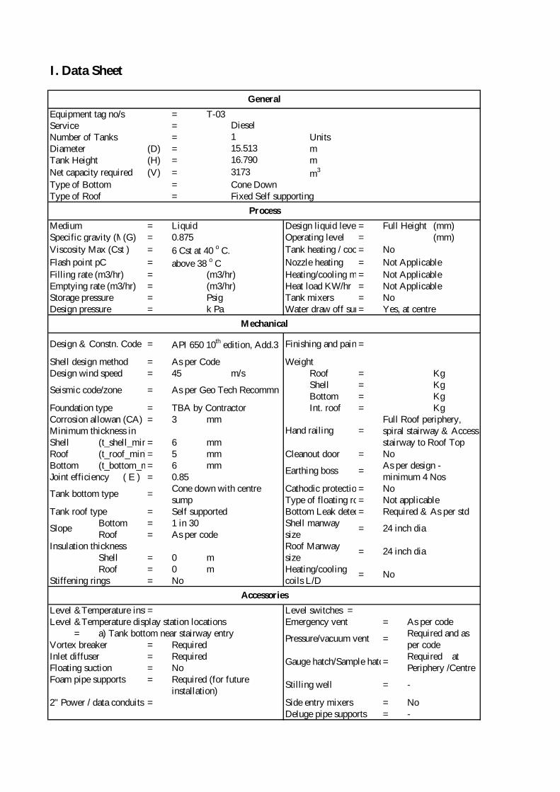
I. Data Sheet
Equipment tag no/s = T-03Service =Number of Tanks = UnitsDiameter (D) = mTank Height (H) = m
Net capacity required (V) = m3
Type of Bottom = Cone DownType of Roof = Fixed Self supporting
Medium = Liquid Design liquid level = Full Height (mm)Specific gravity (Max)(G) = 0.875 Operating level = (mm)
Viscosity Max (Cst ) = 6 Cst at 40 o C. Tank heating / cooling= No
Flash point pC = above 38 o C Nozzle heating = Not Applicable
Filling rate (m3/hr) = (m3/hr) Heating/cooling med= Not ApplicableEmptying rate (m3/hr) = (m3/hr) Heat load KW/hr = Not ApplicableStorage pressure = Psig Tank mixers = NoDesign pressure = k Pa Water draw off sump= Yes, at centre
Shell design method = As per Code Weight Design wind speed = 45 m/s Roof = Kg
Shell = KgBottom = Kg
Foundation type = TBA by Contractor Int. roof = KgCorrosion allowance(CA) = 3 mmMinimum thickness inShell (t_shell_min)= 6 mmRoof (t_roof_min)= 5 mm Cleanout door = NoBottom (t_bottom_min)= 6 mmJoint efficiency ( E ) = 0.85
Cathodic protection= NoType of floating roof= Not applicable
Tank roof type = Self supported Bottom Leak detect= Required & As per stdBottom = 1 in 30Roof = As per code
Insulation thicknessShell = 0 mRoof = 0 m
Stiffening rings = No
Level &Temperature instrument= Level switches =Level &Temperature display station locations Emergency vent = As per code
= a) Tank bottom near stairway entryVortex breaker = RequiredInlet diffuser = RequiredFloating suction = NoFoam pipe supports =
2" Power / data conduits = Side entry mixers = NoDeluge pipe supports =
Process
Mechanical
Design & Constn. Code = API 650 10th edition, Add.3 Finishing and painting=
General
Diesel115.51316.790
3173
SlopeShell manway size
= 24 inch dia
Roof Manway size
= 24 inch dia
Earthing boss =As per design - minimum 4 Nos
Tank bottom type =Cone down with centre sump
Seismic code/zone = As per Geo Tech Recommn
Hand railing =Full Roof periphery, spiral stairway & Access stairway to Roof Top
-
Gauge hatch/Sample hatch=Required ñ at Periphery /Centre
Required (for future installation)
Stilling well = -
Heating/cooling coils L/D
= No
Accessories
Pressure/vacuum vent =Required and as per code

Hydro Test Stress (ST)Yield StrengthBottom plate = Psi Psi PsiShell = Psi Psi PsiRoof plate = Psi Psi PsiShell lining = Psi Psi PsiRoof lining = Psi Psi PsiNozzle/man way lining = Psi Psi PsiNozzle flanges =Nozzle necks =
=
Heating/cooling coils = NoBolts = ASTM A193 Gr. B7 GalvanisedNuts = ASTM A194 Gr.2H GalvanisedWelding fittings = A234 WPB/A105Gaskets = SS 316 spiral wound graphite filledInsulation supports = NoStairs/handrails/platforms= ASTM A36 or equivalent (no galvanising only painted)Earthing boss = Furse makeInternal piping = ASTM A 106 Gr. B and A312 SS304 (3" & below)Gauge Pipe = ASTM A 106 Gr. B
Materials
Design Stress (SD)A-36 23200 24857 36000
None -- -- --A-105A-106 Gr B
None -- -- --None -- -- --
A-36 23200 24857 36000A-36 23200 24857 36000
Level &Temperature instrument Pipes
A-106 Gr B

II. Shell Calculation
SHELL COURSE DESIGN (Bottom Course is #1)
Course #1Material =Corrosion Allow. = 3 mm
API-650 ONE FOOT METHOD
Sd = 160 Mpa (allowable design stress per API-650 Table 3-2)
St = 171 Mpa (allowable test stress)
DESIGN CONDITION G = Specific Gravity
where: td = Minimum Shell Thickness, in mm
D = Nominal Diameter of The Tank, in mH = Design Liquid Level, in mG = Specific Gravity of The Liquid to be Stored, As Specified By The PurchaserCA = Corrosion Allowance, in mm, As Specified By The PurchaserS = Allowable Stress for The Design Condition, in Mpa
H1 = Effective Liquid Head at Design pressure
HYDROSTATIC TEST CONDITION G = Specific Gravity
= H +2.31 . P (psi)
G
= 16.79 +2.31 . 00.875
A-36; Width = 1524 mm
0.875
td =4.9 . D . (H-0.3) . G
+ CASd
td1 =1096.783
+ 3160
+ CASd
td1 =4.9 . 15.513 . (16.79-0.3) . 0.875
+ 3160
H1 = 16.79 m
td1 =4.9 . D . (H-0.3) . G
tt =4.9 . D . (H-0.3)
St
td1 = 9.85 mm
0.875
td1 = 6.85 + 3

where: tt = Minimum Hydrostatic Test Shell Thickness, in mm
D = Nominal Diameter of The Tank, in mH = Design Liquid Level, in mG = Specific Gravity of The Liquid to be Stored, As Specified By The PurchaserCA = Corrosion Allowance, in mm, As Specified By The PurchaserS = Allowable Stress for The Hydrostatic Test Condition, in Mpa
H1 = Effective Liquid Head at Design pressure
Course #2Material =Corrosion Allow. = 3 mm
API-650 ONE FOOT METHOD
Sd = 160 Mpa (allowable design stress per API-650 Table 3-2)
St = 171 Mpa (allowable test stress)
DESIGN CONDITION G = Specific Gravity
where: td = Minimum Shell Thickness, in mm
D = Nominal Diameter of The Tank, in mH = Design Liquid Level, in mG = Specific Gravity of The Liquid to be Stored, As Specified By The PurchaserCA = Corrosion Allowance, in mm, As Specified By The PurchaserS = Allowable Stress for The Design Condition, in Mpa
H2 = Effective Liquid Head at Design pressure
tt1 =4.9 . 15.513 . (16.79-0.3)
171
tt1 =1253.466
171
H1 = 16.79 m
tt1 =4.9 . D . (H1-0.3)
St
= H +2.31 . P (psi)
G
= 16.79 +2.31 . 00.875
= H +2.31 . P (psi)
G
td =4.9 . D . (H-0.3) . G
+ CASd
tt1 = 7.33 mm
A-36; Width = 1524 mm
0.875
HYDROSTATIC TEST CONDITION G = Specific Gravity
where: tt = Minimum Hydrostatic Test Shell Thickness, in mm
D = Nominal Diameter of The Tank, in mH = Design Liquid Level, in mG = Specific Gravity of The Liquid to be Stored, As Specified By The PurchaserCA = Corrosion Allowance, in mm, As Specified By The PurchaserS = Allowable Stress for The Hydrostatic Test Condition, in Mpa
H2 = Effective Liquid Head at Design pressure
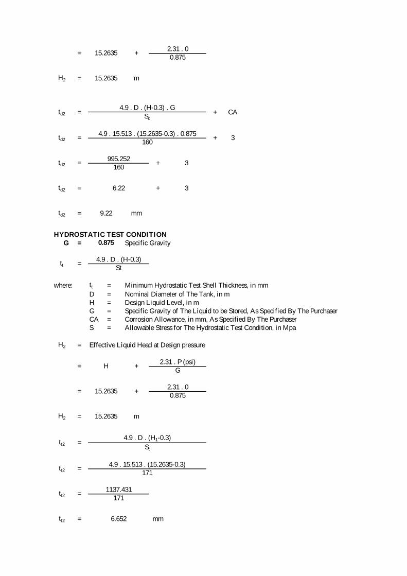
= 15.2635 +2.31 . 00.875
td2 =995.252
+ 3160
+ CASd
td2 =4.9 . 15.513 . (15.2635-0.3) . 0.875
+ 3160
H2 = 15.2635 m
td2 =4.9 . D . (H-0.3) . G
tt =4.9 . D . (H-0.3)
St
td2 = 9.22 mm
0.875
td2 = 6.22 + 3
tt2 =4.9 . 15.513 . (15.2635-0.3)
171
tt2 =1137.431
171
H2 = 15.2635 m
tt2 =4.9 . D . (H1-0.3)
St
= H +2.31 . P (psi)
G
= 15.2635 +2.31 . 00.875
tt2 = 6.652 mm
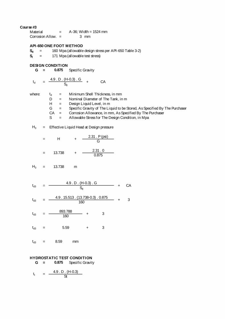
Course #3Material =Corrosion Allow. = 3 mm
API-650 ONE FOOT METHOD
Sd = 160 Mpa (allowable design stress per API-650 Table 3-2)
St = 171 Mpa (allowable test stress)
DESIGN CONDITION G = Specific Gravity
where: td = Minimum Shell Thickness, in mm
D = Nominal Diameter of The Tank, in mH = Design Liquid Level, in mG = Specific Gravity of The Liquid to be Stored, As Specified By The PurchaserCA = Corrosion Allowance, in mm, As Specified By The PurchaserS = Allowable Stress for The Design Condition, in Mpa
H3 = Effective Liquid Head at Design pressure
HYDROSTATIC TEST CONDITION G = Specific Gravity
= H +2.31 . P (psi)
G
= 13.738 +2.31 . 00.875
td =4.9 . D . (H-0.3) . G
+ CASd
A-36; Width = 1524 mm
0.875
td3 =893.788
+ 3160
+ CASd
td3 =4.9 . 15.513 . (13.738-0.3) . 0.875
+ 3160
H3 = 13.738 m
td3 =4.9 . D . (H-0.3) . G
tt =4.9 . D . (H-0.3)
St
td3 = 8.59 mm
0.875
td3 = 5.59 + 3

where: tt = Minimum Hydrostatic Test Shell Thickness, in mm
D = Nominal Diameter of The Tank, in mH = Design Liquid Level, in mG = Specific Gravity of The Liquid to be Stored, As Specified By The PurchaserCA = Corrosion Allowance, in mm, As Specified By The PurchaserS = Allowable Stress for The Hydrostatic Test Condition, in Mpa
H3 = Effective Liquid Head at Design pressure
Course #4Material =Corrosion Allow. = 3 mm
API-650 ONE FOOT METHOD
Sd = 160 Mpa (allowable design stress per API-650 Table 3-2)
St = 171 Mpa (allowable test stress)
DESIGN CONDITION G = Specific Gravity
where: td = Minimum Shell Thickness, in mm
D = Nominal Diameter of The Tank, in mH = Design Liquid Level, in mG = Specific Gravity of The Liquid to be Stored, As Specified By The PurchaserCA = Corrosion Allowance, in mm, As Specified By The PurchaserS = Allowable Stress for The Design Condition, in Mpa
H4 = Effective Liquid Head at Design pressure
tt3 =4.9 . 15.513 . (13.738-0.3)
171
tt3 =1021.472
171
H3 = 13.738 m
tt3 =4.9 . D . (H1-0.3)
St
= H +2.31 . P (psi)
G
= 13.738 +2.31 . 00.875
= H +2.31 . P (psi)
G
td =4.9 . D . (H-0.3) . G
+ CASd
tt3 = 5.974 mm
A-36; Width = 1524 mm
0.875

HYDROSTATIC TEST CONDITION G = Specific Gravity
where: tt = Minimum Hydrostatic Test Shell Thickness, in mm
D = Nominal Diameter of The Tank, in mH = Design Liquid Level, in mG = Specific Gravity of The Liquid to be Stored, As Specified By The PurchaserCA = Corrosion Allowance, in mm, As Specified By The PurchaserS = Allowable Stress for The Hydrostatic Test Condition, in Mpa
H4 = Effective Liquid Head at Design pressure
= 12.2125 +2.31 . 00.875
td4 =792.324
+ 3160
+ CASd
td4 =4.9 . 15.513 . (12.2125-0.3) . 0.875
+ 3160
H4 = 12.2125 m
td4 =4.9 . D . (H-0.3) . G
tt =4.9 . D . (H-0.3)
St
td4 = 7.95 mm
0.875
td4 = 4.95 + 3
tt4 =4.9 . 15.513 . (12.2125-0.3)
171
tt4 =905.513
171
H4 = 12.2125 m
tt4 =4.9 . D . (H1-0.3)
St
= H +2.31 . P (psi)
G
= 12.2125 +2.31 . 00.875
tt4 = 5.295 mm

Course #5Material =Corrosion Allow. = 3 mm
API-650 ONE FOOT METHOD
Sd = 160 Mpa (allowable design stress per API-650 Table 3-2)
St = 171 Mpa (allowable test stress)
DESIGN CONDITION G = Specific Gravity
where: td = Minimum Shell Thickness, in mm
D = Nominal Diameter of The Tank, in mH = Design Liquid Level, in mG = Specific Gravity of The Liquid to be Stored, As Specified By The PurchaserCA = Corrosion Allowance, in mm, As Specified By The PurchaserS = Allowable Stress for The Design Condition, in Mpa
H5 = Effective Liquid Head at Design pressure
HYDROSTATIC TEST CONDITION G = Specific Gravity
= H +2.31 . P (psi)
G
= 10.687 +2.31 . 00.875
td =4.9 . D . (H-0.3) . G
+ CASd
A-36; Width = 1524 mm
0.875
td5 =690.86
+ 3160
+ CASd
td5 =4.9 . 15.513 . (10.687-0.3) . 0.875
+ 3160
H5 = 10.687 m
td5 =4.9 . D . (H-0.3) . G
tt =4.9 . D . (H-0.3)
St
td5 = 7.32 mm
0.875
td5 = 4.32 + 3

where: tt = Minimum Hydrostatic Test Shell Thickness, in mm
D = Nominal Diameter of The Tank, in mH = Design Liquid Level, in mG = Specific Gravity of The Liquid to be Stored, As Specified By The PurchaserCA = Corrosion Allowance, in mm, As Specified By The PurchaserS = Allowable Stress for The Hydrostatic Test Condition, in Mpa
H5 = Effective Liquid Head at Design pressure
Course #6Material =Corrosion Allow. = 3 mm
API-650 ONE FOOT METHOD
Sd = 160 Mpa (allowable design stress per API-650 Table 3-2)
St = 171 Mpa (allowable test stress)
DESIGN CONDITION G = Specific Gravity
where: td = Minimum Shell Thickness, in mm
D = Nominal Diameter of The Tank, in mH = Design Liquid Level, in mG = Specific Gravity of The Liquid to be Stored, As Specified By The PurchaserCA = Corrosion Allowance, in mm, As Specified By The PurchaserS = Allowable Stress for The Design Condition, in Mpa
H6 = Effective Liquid Head at Design pressure
tt5 =4.9 . 15.513 . (10.687-0.3)
171
tt5 =789.554
171
H5 = 10.687 m
tt5 =4.9 . D . (H1-0.3)
St
= H +2.31 . P (psi)
G
= 10.687 +2.31 . 00.875
= H +2.31 . P (psi)
G
td =4.9 . D . (H-0.3) . G
+ CASd
tt5 = 4.617 mm
A-36; Width = 1524 mm
0.875

HYDROSTATIC TEST CONDITION G = Specific Gravity
where: tt = Minimum Hydrostatic Test Shell Thickness, in mm
D = Nominal Diameter of The Tank, in mH = Design Liquid Level, in mG = Specific Gravity of The Liquid to be Stored, As Specified By The PurchaserCA = Corrosion Allowance, in mm, As Specified By The PurchaserS = Allowable Stress for The Hydrostatic Test Condition, in Mpa
H6 = Effective Liquid Head at Design pressure
= 9.1615 +2.31 . 00.875
td6 =589.396
+ 3160
+ CASd
td6 =4.9 . 15.513 . (9.1615-0.3) . 0.875
+ 3160
H6 = 9.1615 m
td6 =4.9 . D . (H-0.3) . G
tt =4.9 . D . (H-0.3)
St
td6 = 6.68 mm
0.875
td6 = 3.68 + 3
tt6 =4.9 . 15.513 . (9.1615-0.3)
171
tt6 =673.595
171
H6 = 9.1615 m
tt6 =4.9 . D . (H1-0.3)
St
= H +2.31 . P (psi)
G
= 9.1615 +2.31 . 00.875
tt6 = 3.939 mm

Course #7Material =Corrosion Allow. = 3 mm
API-650 ONE FOOT METHOD
Sd = 160 Mpa (allowable design stress per API-650 Table 3-2)
St = 171 Mpa (allowable test stress)
DESIGN CONDITION G = Specific Gravity
where: td = Minimum Shell Thickness, in mm
D = Nominal Diameter of The Tank, in mH = Design Liquid Level, in mG = Specific Gravity of The Liquid to be Stored, As Specified By The PurchaserCA = Corrosion Allowance, in mm, As Specified By The PurchaserS = Allowable Stress for The Design Condition, in Mpa
H7 = Effective Liquid Head at Design pressure
HYDROSTATIC TEST CONDITION G = Specific Gravity
= H +2.31 . P (psi)
G
= 7.636 +2.31 . 00.875
td =4.9 . D . (H-0.3) . G
+ CASd
A-36; Width = 1524 mm
0.875
td7 =487.932
+ 3160
+ CASd
td7 =4.9 . 15.513 . (7.636-0.3) . 0.875
+ 3160
H7 = 7.636 m
td7 =4.9 . D . (H-0.3) . G
tt =4.9 . D . (H-0.3)
St
td7 = 6.05 mm
0.875
td7 = 3.05 + 3

where: tt = Minimum Hydrostatic Test Shell Thickness, in mm
D = Nominal Diameter of The Tank, in mH = Design Liquid Level, in mG = Specific Gravity of The Liquid to be Stored, As Specified By The PurchaserCA = Corrosion Allowance, in mm, As Specified By The PurchaserS = Allowable Stress for The Hydrostatic Test Condition, in Mpa
H7 = Effective Liquid Head at Design pressure
Course #8Material =Corrosion Allow. = 3 mm
API-650 ONE FOOT METHOD
Sd = 160 Mpa (allowable design stress per API-650 Table 3-2)
St = 171 Mpa (allowable test stress)
DESIGN CONDITION G = Specific Gravity
where: td = Minimum Shell Thickness, in mm
D = Nominal Diameter of The Tank, in mH = Design Liquid Level, in mG = Specific Gravity of The Liquid to be Stored, As Specified By The PurchaserCA = Corrosion Allowance, in mm, As Specified By The PurchaserS = Allowable Stress for The Design Condition, in Mpa
H8 = Effective Liquid Head at Design pressure
tt7 =4.9 . 15.513 . (7.636-0.3)
171
tt7 =557.637
171
H7 = 7.636 m
tt7 =4.9 . D . (H1-0.3)
St
= H +2.31 . P (psi)
G
= 7.636 +2.31 . 00.875
= H +2.31 . P (psi)
G
td =4.9 . D . (H-0.3) . G
+ CASd
tt7 = 3.261 mm
A-36; Width = 1524 mm
0.875

HYDROSTATIC TEST CONDITION G = Specific Gravity
where: tt = Minimum Hydrostatic Test Shell Thickness, in mm
D = Nominal Diameter of The Tank, in mH = Design Liquid Level, in mG = Specific Gravity of The Liquid to be Stored, As Specified By The PurchaserCA = Corrosion Allowance, in mm, As Specified By The PurchaserS = Allowable Stress for The Hydrostatic Test Condition, in Mpa
H8 = Effective Liquid Head at Design pressure
= 6.1105 +2.31 . 00.875
td8 =386.468
+ 3160
+ CASd
td8 =4.9 . 15.513 . (6.1105-0.3) . 0.875
+ 3160
H8 = 6.1105 m
td8 =4.9 . D . (H-0.3) . G
tt =4.9 . D . (H-0.3)
St
td8 = 5.42 mm
0.875
td8 = 2.42 + 3
tt8 =4.9 . 15.513 . (6.1105-0.3)
171
tt8 =441.678
171
H8 = 6.1105 m
tt8 =4.9 . D . (H1-0.3)
St
= H +2.31 . P (psi)
G
= 6.1105 +2.31 . 00.875
tt8 = 2.583 mm

Course #9Material =Corrosion Allow. = 3 mm
API-650 ONE FOOT METHOD
Sd = 160 Mpa (allowable design stress per API-650 Table 3-2)
St = 171 Mpa (allowable test stress)
DESIGN CONDITION G = Specific Gravity
where: td = Minimum Shell Thickness, in mm
D = Nominal Diameter of The Tank, in mH = Design Liquid Level, in mG = Specific Gravity of The Liquid to be Stored, As Specified By The PurchaserCA = Corrosion Allowance, in mm, As Specified By The PurchaserS = Allowable Stress for The Design Condition, in Mpa
H9 = Effective Liquid Head at Design pressure
HYDROSTATIC TEST CONDITION G = Specific Gravity
= H +2.31 . P (psi)
G
= 4.585 +2.31 . 00.875
td =4.9 . D . (H-0.3) . G
+ CASd
A-36; Width = 1524 mm
0.875
td9 =285.004
+ 3160
+ CASd
td9 =4.9 . 15.513 . (4.585-0.3) . 0.875
+ 3160
H9 = 4.585 m
td9 =4.9 . D . (H-0.3) . G
tt =4.9 . D . (H-0.3)
St
td9 = 4.78 mm
0.875
td9 = 1.78 + 3
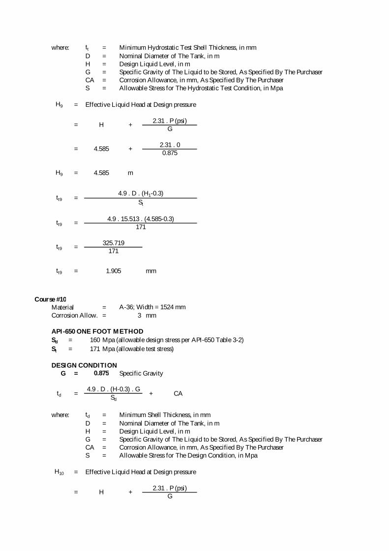
where: tt = Minimum Hydrostatic Test Shell Thickness, in mm
D = Nominal Diameter of The Tank, in mH = Design Liquid Level, in mG = Specific Gravity of The Liquid to be Stored, As Specified By The PurchaserCA = Corrosion Allowance, in mm, As Specified By The PurchaserS = Allowable Stress for The Hydrostatic Test Condition, in Mpa
H9 = Effective Liquid Head at Design pressure
Course #10Material =Corrosion Allow. = 3 mm
API-650 ONE FOOT METHOD
Sd = 160 Mpa (allowable design stress per API-650 Table 3-2)
St = 171 Mpa (allowable test stress)
DESIGN CONDITION G = Specific Gravity
where: td = Minimum Shell Thickness, in mm
D = Nominal Diameter of The Tank, in mH = Design Liquid Level, in mG = Specific Gravity of The Liquid to be Stored, As Specified By The PurchaserCA = Corrosion Allowance, in mm, As Specified By The PurchaserS = Allowable Stress for The Design Condition, in Mpa
H10 = Effective Liquid Head at Design pressure
tt9 =4.9 . 15.513 . (4.585-0.3)
171
tt9 =325.719
171
H9 = 4.585 m
tt9 =4.9 . D . (H1-0.3)
St
= H +2.31 . P (psi)
G
= 4.585 +2.31 . 00.875
= H +2.31 . P (psi)
G
td =4.9 . D . (H-0.3) . G
+ CASd
tt9 = 1.905 mm
A-36; Width = 1524 mm
0.875
HYDROSTATIC TEST CONDITION G = Specific Gravity
where: tt = Minimum Hydrostatic Test Shell Thickness, in mm
D = Nominal Diameter of The Tank, in mH = Design Liquid Level, in mG = Specific Gravity of The Liquid to be Stored, As Specified By The PurchaserCA = Corrosion Allowance, in mm, As Specified By The PurchaserS = Allowable Stress for The Hydrostatic Test Condition, in Mpa
H10 = Effective Liquid Head at Design pressure
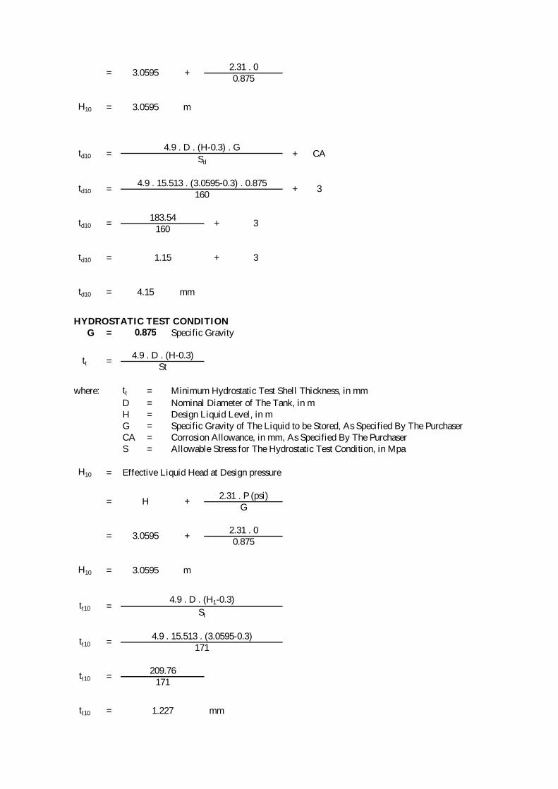
= 3.0595 +2.31 . 00.875
td10 =183.54
+ 3160
+ CASd
td10 =4.9 . 15.513 . (3.0595-0.3) . 0.875
+ 3160
H10 = 3.0595 m
td10 =4.9 . D . (H-0.3) . G
tt =4.9 . D . (H-0.3)
St
td10 = 4.15 mm
0.875
td10 = 1.15 + 3
tt10 =4.9 . 15.513 . (3.0595-0.3)
171
tt10 =209.76
171
H10 = 3.0595 m
tt10 =4.9 . D . (H1-0.3)
St
= H +2.31 . P (psi)
G
= 3.0595 +2.31 . 00.875
tt10 = 1.227 mm

Course #11Material =Corrosion Allow. = 3 mm
API-650 ONE FOOT METHOD
Sd = 160 Mpa (allowable design stress per API-650 Table 3-2)
St = 171 Mpa (allowable test stress)
DESIGN CONDITION G = Specific Gravity
where: td = Minimum Shell Thickness, in mm
D = Nominal Diameter of The Tank, in mH = Design Liquid Level, in mG = Specific Gravity of The Liquid to be Stored, As Specified By The PurchaserCA = Corrosion Allowance, in mm, As Specified By The PurchaserS = Allowable Stress for The Design Condition, in Mpa
H11 = Effective Liquid Head at Design pressure
HYDROSTATIC TEST CONDITION G = Specific Gravity
= H +2.31 . P (psi)
G
= 1.534 +2.31 . 00.875
td =4.9 . D . (H-0.3) . G
+ CASd
A-36; Width = 1524 mm
0.875
td11 =82.076
+ 3160
+ CASd
td11 =4.9 . 15.513 . (1.534-0.3) . 0.875
+ 3160
H11 = 1.534 m
td11 =4.9 . D . (H-0.3) . G
tt =4.9 . D . (H-0.3)
St
td11 = 3.51 mm
0.875
td11 = 0.51 + 3

where: tt = Minimum Hydrostatic Test Shell Thickness, in mm
D = Nominal Diameter of The Tank, in mH = Design Liquid Level, in mG = Specific Gravity of The Liquid to be Stored, As Specified By The PurchaserCA = Corrosion Allowance, in mm, As Specified By The PurchaserS = Allowable Stress for The Hydrostatic Test Condition, in Mpa
H11 = Effective Liquid Head at Design pressure
SHELL COURSE#1 SUMMARY
trequired = MAX (td1;tt1;tminAPI650)
= MAX (9.85;7.33;6)
trequired = 9.85 mm
tactual = 12 mm
Weight = π . D . L . ρ . tactual
= 3.14 . 15.513 . 1.524 . 7.850 . 12= 6997 kg
SHELL COURSE#2 SUMMARY
trequired = MAX (td2;tt2;tminAPI650)
= MAX (9.22;6.652;6)
trequired = 9.22 mm
tactual = 12 mm
Weight = π . D . L . ρ . tactual
= 3.14 . 15.513 . 1.524 . 7.850 . 12= 6997 kg
H11 = 1.534 m
tt11 =4.9 . D . (H1-0.3)
St
= H +2.31 . P (psi)
G
= 1.534 +2.31 . 00.875
tt11 = 0.549 mm
tt11 =4.9 . 15.513 . (1.534-0.3)
171
tt11 =93.801
171

SHELL COURSE#3 SUMMARY
trequired = MAX (td3;tt3;tminAPI650)
= MAX (8.59;5.974;6)
trequired = 8.59 mm
tactual = 10 mm
Weight = π . D . L . ρ . tactual
= 3.14 . 15.513 . 1.524 . 7.850 . 10= 5830 kg
SHELL COURSE#4 SUMMARY
trequired = MAX (td4;tt4;tminAPI650)
= MAX (7.95;5.295;6)
trequired = 7.95 mm
tactual = 10 mm
Weight = π . D . L . ρ . tactual
= 3.14 . 15.513 . 1.524 . 7.850 . 10= 5830 kg
SHELL COURSE#5 SUMMARY
trequired = MAX (td5;tt5;tminAPI650)
= MAX (7.32;4.617;6)
trequired = 7.32 mm
tactual = 10 mm
Weight = π . D . L . ρ . tactual
= 3.14 . 15.513 . 1.524 . 7.850 . 10= 5830 kg
SHELL COURSE#6 SUMMARY
trequired = MAX (td6;tt6;tminAPI650)
= MAX (6.68;3.939;6)
trequired = 6.68 mm
tactual = 8 mm
Weight = π . D . L . ρ . tactual
= 3.14 . 15.513 . 1.524 . 7.850 . 8= 4664 kg
SHELL COURSE#7 SUMMARY
trequired = MAX (td7;tt7;tminAPI650)
= MAX (6.05;3.261;6)
trequired = 6.05 mm
tactual = 8 mm

Weight = π . D . L . ρ . tactual
= 3.14 . 15.513 . 1.524 . 7.850 . 8= 4664 kg
SHELL COURSE#8 SUMMARY
trequired = MAX (td8;tt8;tminAPI650)
= MAX (5.42;2.583;6)
trequired = 6.00 mm
tactual = 8 mm
Weight = π . D . L . ρ . tactual
= 3.14 . 15.513 . 1.524 . 7.850 . 8= 4664 kg
SHELL COURSE#9 SUMMARY
trequired = MAX (td9;tt9;tminAPI650)
= MAX (4.78;1.905;6)
trequired = 6.00 mm
tactual = 8 mm
Weight = π . D . L . ρ . tactual
= 3.14 . 15.513 . 1.524 . 7.850 . 8= 4664 kg
SHELL COURSE#10 SUMMARY
trequired = MAX (td10;tt10;tminAPI650)
= MAX (4.15;1.227;6)
trequired = 6.00 mm
tactual = 8 mm
Weight = π . D . L . ρ . tactual
= 3.14 . 15.513 . 1.524 . 7.850 . 8= 4664 kg
SHELL COURSE#11 SUMMARY
trequired = MAX (td11;tt11;tminAPI650)
= MAX (3.51;0.549;6)
trequired = 6.00 mm
tactual = 6 mm
Weight = π . D . L . ρ . tactual
= 3.14 . 15.513 . 1.524 . 7.850 . 6= 3498 kg

III. Bottom Calculation
FLAT BOTTOM : ANNULAR PLATE DESIGNBottom Plate Material: A-36/SS400Annular Bottom Plate Material: A-36/SS400
<Weight of Bottom Plate>
Bottom_Area = 0.25 . π (ID - 2. AnnRing Width)2
= 0.25 . π (15.513 - 2 . 0.889)2
= 148.17 m2
Annular_Area = 0.25 . π(Bottom Dia)2 - Bottom Area= 0.25 . 3.14 (15.737)^2 - 148.17
= 46.34 m2
Weight = ρ (tb . Bottom_Area + ta . Annular_Area)
= 7850 (0.008 . 148.17 + 0.012 . 46.34)= 13670 kg
<API-650> Calculation of Hydrostatic Test Stress & Product Design Stress (per API-650 Section 3.5.1)
td1 = Bottom (1st) Shell Course Thickness
H = Max. Liq. Level + P(psi)/(0.433)= 55.085 + (0)/(0.433)= 55.085 ft= 16.79 m
St = Hydrostatic Test Stress in bottom (1st) Shell Course
St = 104.46 MPa
Sd = Product Design Stress in bottom (1st) Shell Course
= 121.86 MPa
For Non-Annular Bottom Plates,
tbt,min = 6 mm (per Section 3.4.1)
tbt = tbt,min
tbt = 6 mm
tbt,acc = Actual Non-Annular Bottom hickness
= 8 mm
=4.9 . D . (H - 0.3)
td1
=4.9 . 15.513 . (16.79- 0.3)
12
=4.9 . 15.513 . (16.79- 0.3). 0.875
12 - 3
=1096.78
9
=1253.47
12
=4.9 . D . (H - 0.3). G
td1 - CA
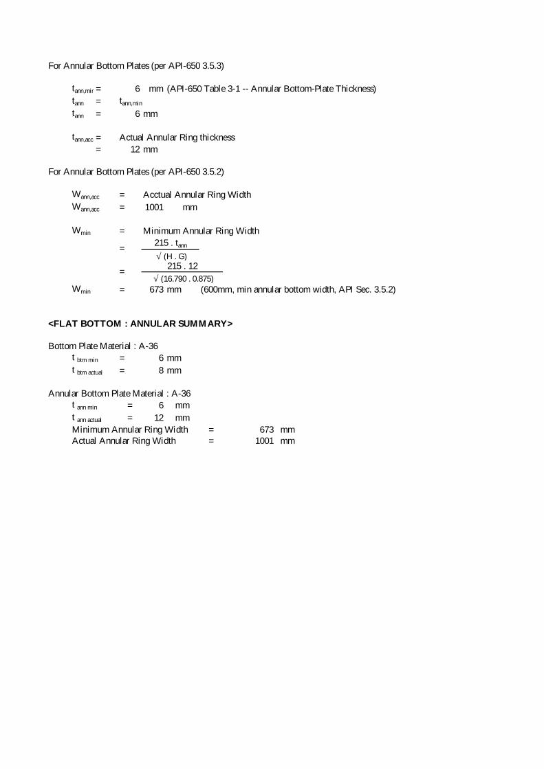
For Annular Bottom Plates (per API-650 3.5.3)
tann,min = 6 mm (API-650 Table 3-1 -- Annular Bottom-Plate Thickness)
tann = tann,min
tann = 6 mm
tann,acc = Actual Annular Ring thickness
= 12 mm
For Annular Bottom Plates (per API-650 3.5.2)
Wann,acc = Acctual Annular Ring Width
Wann,acc = 1001 mm
Wmin = Minimum Annular Ring Width
Wmin = 673 mm (600mm, min annular bottom width, API Sec. 3.5.2)
<FLAT BOTTOM : ANNULAR SUMMARY>
Bottom Plate Material : A-36t btm min = 6 mm
t btm actual = 8 mm
Annular Bottom Plate Material : A-36t ann min = 6 mm
t ann actual = 12 mm
Minimum Annular Ring Width = 673 mmActual Annular Ring Width = 1001 mm
=215 . tann
√ (H . G)
=215 . 12
√ (16.790 . 0.875)