technical data sheet 160421
TRANSCRIPT
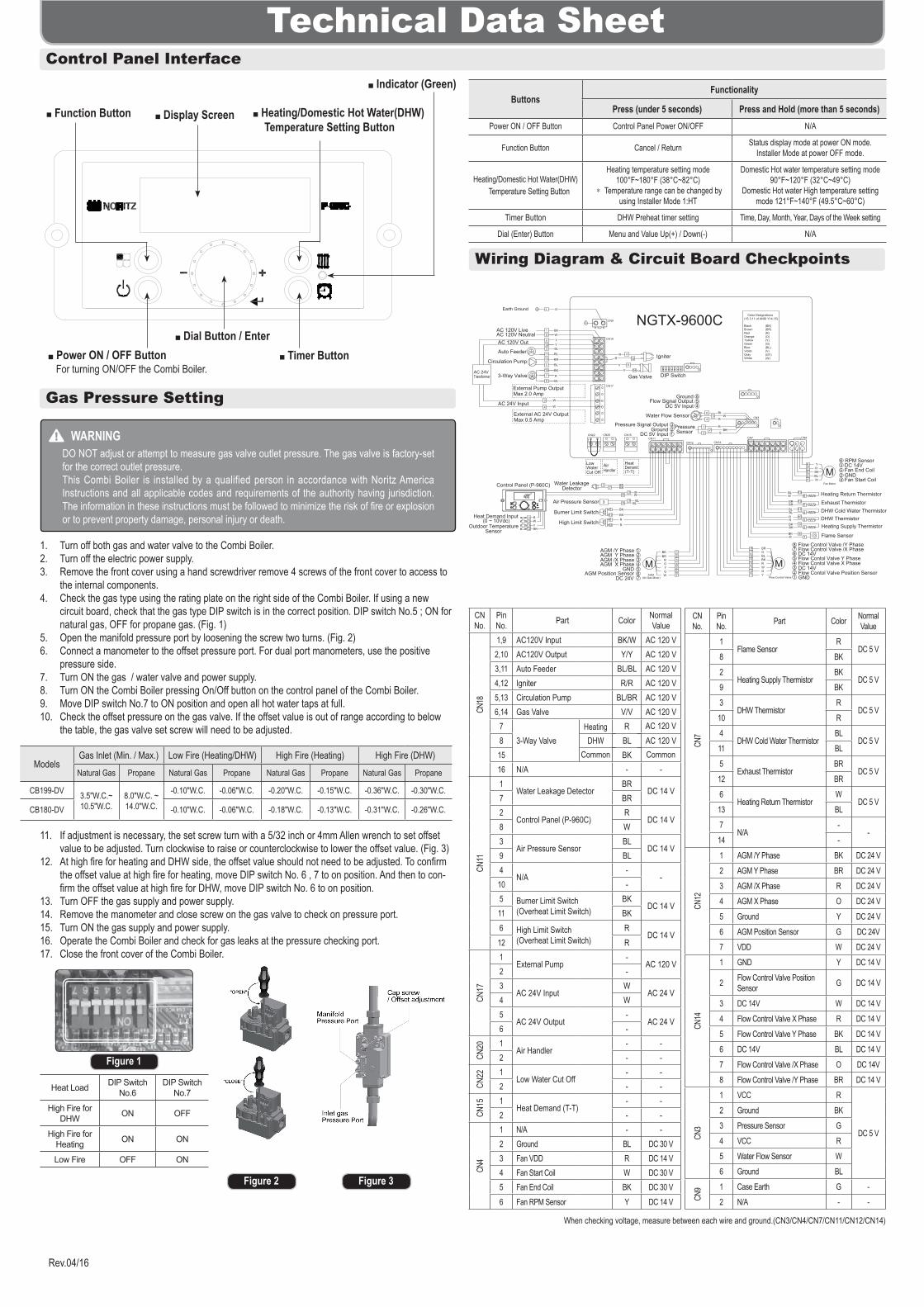
Technical Data SheetControl Panel Interface
Display Screen
Indicator (Green)
Heating/Domestic Hot Water(DHW) Temperature Setting Button
Timer Button Dial Button / Enter
Power ON / OFF Button For turning ON/OFF the Combi Boiler.
Rev.04/16
Function ButtonButtons
Functionality
Press (under 5 seconds) Press and Hold (more than 5 seconds)Power ON / OFF Button Control Panel Power ON/OFF N/A
Function Button Cancel / Return Status display mode at power ON mode.Installer Mode at power OFF mode.
Heating/Domestic Hot Water(DHW) Temperature Setting Button
Heating temperature setting mode100°F~180°F (38°C~82°C)
* Temperature range can be changed by using Installer Mode 1:HT
Domestic Hot water temperature setting mode 90°F~120°F (32°C~49°C)
Domestic Hot water High temperature setting mode 121°F~140°F (49.5°C~60°C)
Timer Button DHW Preheat timer setting Time, Day, Month, Year, Days of the Week setting
Dial (Enter) Button Menu and Value Up(+) / Down(-) N/A
Gas Pressure Setting
WARNINGDO NOT adjust or attempt to measure gas valve outlet pressure. The gas valve is factory-set for the correct outlet pressure.This Combi Boiler is installed by a qualified person in accordance with Noritz America Instructions and all applicable codes and requirements of the authority having jurisdiction. The information in these instructions must be followed to minimize the risk of fire or explosion or to prevent property damage, personal injury or death.
1. Turn off both gas and water valve to the Combi Boiler.2. Turn off the electric power supply.3. Remove the front cover using a hand screwdriver remove 4 screws of the front cover to access to
the internal components.4. Check the gas type using the rating plate on the right side of the Combi Boiler. If using a new
circuit board, check that the gas type DIP switch is in the correct position. DIP switch No.5 ; ON for natural gas, OFF for propane gas. (Fig. 1)
5. Open the manifold pressure port by loosening the screw two turns. (Fig. 2)6. Connect a manometer to the offset pressure port. For dual port manometers, use the positive
pressure side.7. Turn ON the gas / water valve and power supply.8. Turn ON the Combi Boiler pressing On/Off button on the control panel of the Combi Boiler.9. Move DIP switch No.7 to ON position and open all hot water taps at full. 10. Check the offset pressure on the gas valve. If the offset value is out of range according to below
the table, the gas valve set screw will need to be adjusted.
11. If adjustment is necessary, the set screw turn with a 5/32 inch or 4mm Allen wrench to set offset value to be adjusted. Turn clockwise to raise or counterclockwise to lower the offset value. (Fig. 3)
12. At high fire for heating and DHW side, the offset value should not need to be adjusted. To confirm the offset value at high fire for heating, move DIP switch No. 6 , 7 to on position. And then to con-firm the offset value at high fire for DHW, move DIP switch No. 6 to on position.
13. Turn OFF the gas supply and power supply.14. Remove the manometer and close screw on the gas valve to check on pressure port.15. Turn ON the gas supply and power supply.16. Operate the Combi Boiler and check for gas leaks at the pressure checking port.17. Close the front cover of the Combi Boiler.
ModelsGas Inlet (Min. / Max.) Low Fire (Heating/DHW) High Fire (Heating) High Fire (DHW)Natural Gas Propane Natural Gas Propane Natural Gas Propane Natural Gas Propane
CB199-DV 3.5"W.C.~ 10.5"W.C.
8.0"W.C. ~ 14.0"W.C.
-0.10"W.C. -0.06"W.C. -0.20"W.C. -0.15"W.C. -0.36"W.C. -0.30"W.C.
CB180-DV -0.10"W.C. -0.06"W.C. -0.18"W.C. -0.13"W.C. -0.31"W.C. -0.26"W.C.
Figure 3Figure 2
Figure 1
Wiring Diagram & Circuit Board Checkpoints
CN No.
Pin No. Part Color Normal
Value
CN18
1,9 AC120V Input BK/W AC 120 V2,10 AC120V Output Y/Y AC 120 V3,11 Auto Feeder BL/BL AC 120 V4,12 Igniter R/R AC 120 V5,13 Circulation Pump BL/BR AC 120 V6,14 Gas Valve V/V AC 120 V
73-Way Valve DHW
RAC 120 V8 BL
15 BK16 N/A - -
CN11
1Water Leakage Detector
BRDC 14 V
7 BR2
Control Panel (P-960C)R
DC 14 V8 W3
Air Pressure SensorBL
DC 14 V9 BL4
N/A-
-10 -5 Burner Limit Switch
(Overheat Limit Switch)BK
DC 14 V11 BK6 High Limit Switch
(Overheat Limit Switch)R
DC 14 V12 R
CN17
1External Pump
-AC 120 V
2 -3
AC 24V InputW
AC 24 V4 W5
AC 24V Output-
AC 24 V6 -
CN20 1
Air Handler- -
2 - -
CN22 1
Low Water Cut Off- -
2 - -
CN15 1
Heat Demand (T-T)- -
2 - -
CN4
1 N/A - -2 Ground BL DC 30 V3 Fan VDD R DC 14 V4 Fan Start Coil W DC 30 V5 Fan End Coil BK DC 30 V6 Fan RPM Sensor Y DC 14 V
CN No.
Pin No. Part Color Normal
Value
CN7
1Flame Sensor
RDC 5 V
8 BK2
Heating Supply ThermistorBK
DC 5 V9 BK3
DHW ThermistorR
DC 5 V10 R4
DHW Cold Water ThermistorBL
DC 5 V11 BL5
Exhaust ThermistorBR
DC 5 V12 BR6
Heating Return ThermistorW
DC 5 V13 BL7
N/A-
-14 -
CN12
1 AGM /Y Phase BK DC 24 V 2 AGM Y Phase BR DC 24 V3 AGM /X Phase R DC 24 V4 AGM X Phase O DC 24 V5 Ground Y DC 24 V6 AGM Position Sensor G DC 24V7 VDD W DC 24 V
CN14
1 GND Y DC 14 V
2 Flow Control Valve Position Sensor G DC 14 V
3 DC 14V W DC 14 V4 Flow Control Valve X Phase R DC 14 V5 Flow Control Valve Y Phase BK DC 14 V6 DC 14V BL DC 14 V7 Flow Control Valve /X Phase O DC 14V8 Flow Control Valve /Y Phase BR DC 14 V
CN3
1 VCC R
DC 5 V
2 Ground BK3 Pressure Sensor G4 VCC R5 Water Flow Sensor W6 Ground BL
CN9 1 Case Earth G -
2 N/A - -
Heat Load DIP Switch No.6
DIP Switch No.7
High Fire for DHW ON OFF
High Fire for Heating ON ON
Low Fire OFF ON
When checking voltage, measure between each wire and ground.(CN3/CN4/CN7/CN11/CN12/CN14)
AC 120 VHeating
Common Common
3
Fan Start CoilGNDFan End CoilDC 14VRPM Sensor6
25
4
Burner Limit Switch
High Limit Switch
39
5
116
12
BK
BKR
R
BLBL
AGM /Y Phase 1 BK 1AGM Y PhaseAGM /X PhaseAGM X Phase
GNDAGM Position Sensor
DC 24V
5432
67
MGYOR
BR
654
23
W 7AGM(Air Gas Mixer)
DHW ThermistorHeating Supply Thermistor2
93
104
11
BKBKRRBLBL
512
BRBR
18BK
R
MR
BL
Y
W
BK36
25
4
Exhaust Thermistor
6 BL5 W
4 R
DC 5V InputFlow Signal Output
Ground54
6
28
RW
BKW
1 9
DIP Switch
Flame Sensor
BL
BL
3
4
613
12
3
PressurePressure Signal OutputGround 2
1
3 R
GBK
NGTX-9600C
MBLBKRWG
654
23
O7
Y1Flow Control Valve
BR8
Water Flow Sensor
Flow Contol Valve Y Phase
Flow Control Valve /Y Phase
Flow Contol Valve X Phase
Flow Control Valve /X Phase
GNDFlow Contol Valve Position Sensor
543
12
678
DC 14V
DC 14V
Fan Motor
Heating Return Thermistor
DHW Cold Water Thermistor
WBL
G1Earth Ground
IgniterRRBR
BL
V
V
BK
BLR
412
6
14
17 BR
BRDetector
AC 120V NeutralAC 120V Live
Auto Feeder
Air Pressure Sensor
YY
210AC 120V Out
Circulation Pump
3-Way Valve
1234
WR
YBK
Heat Demand Input(0 ~ 10Vdc)
W
W
3
11
13
5
15
7
8
AC 24V Input
Gas Valve
DC 5V Input
Outdoor TemperatureSensor
AC 24VTransformer
LowWaterCut Off
AirHandler
HeatDemand(T-T)
External Pump OutputMax 2.0 Amp
External AC 24V OutputMax 0.5 Amp
SensorCN4CN7
CN14CN12CN11
CN15CN20CN22
CN17
CN18
CN9
CN3
Color Designations(15-3.11 of ANSI Y14.15)
BlackBrownRedOrangeYellowGreenBlueVioletGrayWhite
(BK)(BR)(R)(O)(Y)(G)(BL)(V)(GY)(W)
Water LeakageControl Panel (P-960C)
Display Operation DescriptionA:GA/L DHW Flow Rate • Current Flow Rate (GA: GPM/°F/psi(Default) or L: LPM/°C/BAR)b:FM Fan Speed • Current Fan SpeedC:TL Lock Mode • Lock mode is used (On) or unused (oFF)
d:TP
H.SUP • Current (Heating Supply Thermistor) temperature (°F / °C)H.rEt • Current (Heating Return Thermistor) temperature (°F / °C)d.Hot • Current (DHW Thermistor) temperature (°F / °C)d.CLd • Current (DHW Cold Water Thermistor) temperature (°F / °C)Eht • Current (Exhaust Thermistor) temperature (°F / °C)Od • Current (Oudoor Temperature Sensor) temperature (°F / °C)
E:WP Heating Water Pressure • Current Heating Water Pressure ( psi / BAR )F:FS Valtage of Flame Sensor • Current Flame Sensor (Vdc)g:EH Error History • View the Error History (E0:XX ~ E9:XX)
H:RH(Running History)
PLUg • X 1000 hour (Power-on Time)bnH.H • X 1000 hour (Heating Burn Hour)bnH.d • X 1000 hour (DHW Burn Hour)bnC.H • X 1000 Time (Heating Burn Cycle)bnC.d • X 1000 Time (DHW Burn Cycle)PPHr • X 1000 hour (Pump Running Time)
I:MD 199A / 180A • Model (199A:CB199-DV, 180A:CB180-DV)J:GT ng/LP • Current Gas type.K:Pr Pcb / PnL • Current Software version.(Pcb:Circuit Board, PnL:Control Panel)
Display Operation Description
1:HTHI (Heating Max Temperature) • 121°F (49.5°C) ~ 180°F( 82°C) (Min Temperature ~ Max Temperature).
Default ‘180°F (82°C)’
Lo (Heating Min Temperature) • 80°F (26.5°C) ~ 120°F (49°C) (Min Temperature ~ Max Temperature). Default ‘100°F (38°C)’
2:TR oFF / on • Enable(on) / Disable(oFF) Outdoor Reset Control. Default ‘oFF’ *3:TY, 4:Od and 5:bS can’t be seen if 2:TR is oFF
3:TY
A.Ftb (Finned Tube Baseboard) • 120°F (49°C) ~ 180°F (82°C) (Min Temperature ~ Max Temperature) Defaultb.AH (Air Handler) • 140°F (60°C) ~ 180°F (82°C) (Min Temperature ~ Max Temperature)C.CIb (Cast Iron Baseboard) • 100°F (38°C) ~ 170°F (76.5°C) (Min Temperature ~ Max Temperature)d.LrF (Low Mass Radiant) • 80°F (26.5°C) ~ 140°F (60°C) (Min Temperature ~ Max Temperature)E.rF (Mass Radiant) • 80°F (26.5°C) ~ 120°F (49°C) (Min Temperature ~ Max Temperature)F.rAd (Radiators) • 120°F (49°C) ~ 170°F (76.5°C) (Min Temperature ~ Max Temperature)
G.CUS (Customer Set)
HI • 121°F (49.5°C) ~ 180°F (82°C) (Min Temperature ~ Max Temperature) Default ‘180°F (82°C)’
Lo • 80°F (26.5°C) ~ 120°F (49°C) (Min Temperature ~ Max Temperature) Default ‘100°F (38°C)’
4:Od
A.HI (Highest Outdoor Temperature) • [C.Lo + 9°F(5°C)] ~ 100°F (38°C). Default ‘70°F (21°C)’
b.noH (Warm Weather Cutoff) • on / oFF Default ‘on’, The unit stops heating at A .HI +5°F (2.5°C) automatically. <note> The unit restarts heating at A .HI automatically.
C.Lo (Lowest Outdoor Temperature) • - 4°F (-20°C)~ [A.Hl - 9°F(5°C)]. Default ‘20°F (-6.5°C)’5:bS oFF, 1~120 (minutes) • Setting the Boost Time. Default ‘oFF’6:Vt PVC / CPVC(PP) • Select the PVC Vent or CPVC(PP) Vent. Default ‘PVC’
7:EL
High Elevation • Select an altitude range from the following four options based on where the Combi Boiler is installed.
0-2 0 ~ 1,999 ft (0 ~609 m) (default)2-5 2,000 ~ 4,999 ft (610 ~ 1,523 m)5-8 5,000 ~ 7,999 ft (1,524 ~ 2,438 m)8-10 8,000 ~ 10,000 ft (2,439 ~ 3,048 m)
8:AH on / oFF • Connect the Air Handler(Option). Default ‘oFF’9:PH on / oFF • Setting the DHW Preheat. Default ‘oFF’10:EP on / oFF • Connect the External Pump(Option). Default ‘oFF’11:WP 12 ~ 26 (psi) • Setting the Auto Feeder Pressure. Default ‘12 psi’12:IV 0 ~ 20 (minutes) • Setting the Re-Combustion Interval. Default ‘3 minutes’
13:OrHEAt 0 ~ 60 (minutes) • Setting the Pump Overrun Time in Heating mode. Default ‘20 minutes’do.H 1 ~ 20 (minutes) • Setting the DHW Mode Maintain Time in DHW mode. Default ‘3 minutes’
14:bTA.oFF 0°F (0°C) ~
30°F (16.5°C) • Heating mode Burner OFF : (Setting Temperature) + 0 ~ 30°F(16.5°C). Default ‘10°F(5.5°C)’
b.on 1°F (0.5°C) ~ 30°F (16.5°C)
• Heating mode Burner ON : (Setting Temperature) - 1 ~ 30°F(-0.5~16.5°C). Default ‘30°F(16.5°C)’
15:CK
A.PP on / oFF • Select only Pump operation mode. Default’ ‘oFF’b.FAn 0 ~ 100(%) • Select only Fan operation mode. Default ‘0%’C.Ag on / oFF • Select only AGM Zero Point Check mode. Default ‘oFF’d.3-y on / oFF • Select only 3-Way Valve operation mode. Default ‘oFF’E.FC on / oFF • Select only Flow Control Valve Zero Point Check mode. Default ‘oFF’
16:CLEHIS YES / no • Error History Clear. Default ’no’SYS YES / no • System Clear. Default ’no’
17:FS
A.FH2 - 30 ~ 30 • Maximum Fan RPM compensation in DHW mode : ±30.b.FH1 - 30 ~ 30 • Maximum Fan RPM compensation in Heating mode : ±30.C.FL - 30 ~ 30 • Minimum Fan RPM compensation : ±30.d.Ag - 50 ~ 50 • AGM Position compensation : ±50.
18:CPHEAt 50 ~ 100 (%) • Setting the Max Capacity for Heating. Default ‘100%’do.H 50 ~ 100 (%) • Setting the Max Capacity for DHW. Default ‘100%’
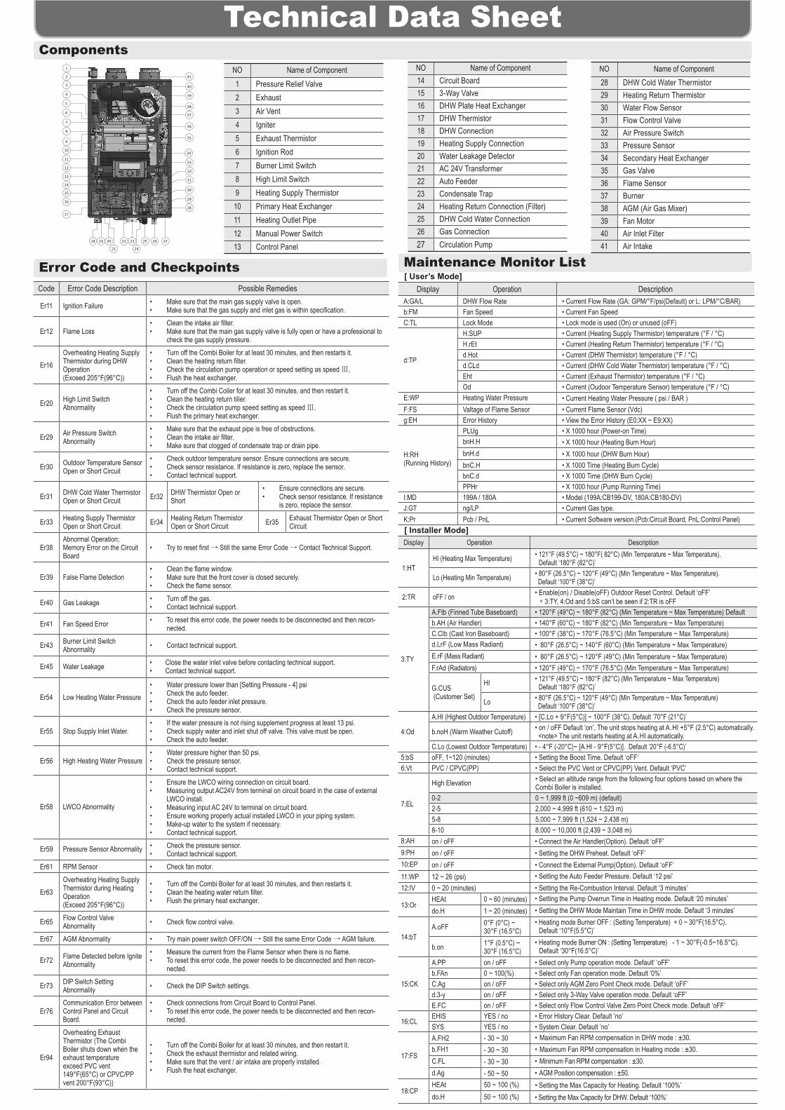
Technical Data SheetComponents
Code Error Code Description Possible Remedies
Er11 Ignition Failure • Make sure that the main gas supply valve is open.• Make sure that the gas supply and inlet gas is within specification.
Er12 Flame Loss• Clean the intake air filter.• Make sure that the main gas supply valve is fully open or have a professional to
check the gas supply pressure.
Er16Overheating Heating Supply Thermistor during DHW Operation(Exceed 205°F(96°C))
• Turn off the Combi Boiler for at least 30 minutes, and then restarts it.• Clean the heating return filter.• Check the circulation pump operation or speed setting as speed Ⅲ.• Flush the heat exchanger.
Er20 High Limit SwitchAbnormality
• Turn off the Combi Coiler for at least 30 minutes, and then restart it.• Clean the heating return tilier.• Check the circulation pump speed setting as speed Ⅲ.• Flush the primary heat exchanger.
Er29 Air Pressure SwitchAbnormality
• Make sure that the exhaust pipe is free of obstructions.• Clean the intake air filter.• Make sure that clogged of condensate trap or drain pipe.
Er30 Outdoor Temperature Sensor Open or Short Circuit
• Check outdoor temperature sensor. Ensure connections are secure.• Check sensor resistance. If resistance is zero, replace the sensor.• Contact technical support.
Er31 DHW Cold Water Thermistor Open or Short Circuit Er32 DHW Thermistor Open or
Short• Ensure connections are secure.• Check sensor resistance. If resistance
is zero, replace the sensor.
Er33 Heating Supply Thermistor Open or Short Circuit Er34 Heating Return Thermistor
Open or Short Circuit Er35 Exhaust Thermistor Open or Short Circuit
Er38Abnormal Operation; Memory Error on the Circuit Board
• Try to reset first → Still the same Error Code → Contact Technical Support.
Er39 False Flame Detection• Clean the flame window.• Make sure that the front cover is closed securely. • Check the flame sensor.
Er40 Gas Leakage • Turn off the gas.• Contact technical support.
Er41 Fan Speed Error • To reset this error code, the power needs to be disconnected and then recon-nected.
Er43 Burner Limit Switch Abnormality • Contact technical support.
Er45 Water Leakage • Close the water inlet valve before contacting technical support.• Contact technical support.
Er54 Low Heating Water Pressure• Water pressure lower than [Setting Pressure - 4] psi• Check the auto feeder.• Check the auto feeder inlet pressure.• Check the pressure sensor.
Er55 Stop Supply Inlet Water.• If the water pressure is not rising supplement progress at least 13 psi.• Check supply water and inlet shut off valve. This valve must be open.• Check the auto feeder.
Er56 High Heating Water Pressure• Water pressure higher than 50 psi.• Check the pressure sensor.• Contact technical support.
Er58 LWCO Abnormality
• Ensure the LWCO wiring connection on circuit board.• Measuring output AC24V from terminal on circuit board in the case of external
LWCO install.• Measuring input AC 24V to terminal on circuit board.• Ensure working properly actual installed LWCO in your piping system.• Make-up water to the system if necessary.• Contact technical support.
Er59 Pressure Sensor Abnormality • Check the pressure sensor.• Contact technical support.
Er61 RPM Sensor • Check fan motor.
Er63Overheating Heating Supply Thermistor during Heating Operation(Exceed 205°F(96°C))
• Turn off the Combi Boiler for at least 30 minutes, and then restarts it.• Clean the heating water return filter.• Flush the primary heat exchanger.
Er65 Flow Control Valve Abnormality • Check flow control valve.
Er67 AGM Abnormality • Try main power switch OFF/ON → Still the same Error Code → AGM failure.
Er72 Flame Detected before Ignite Abnormality
• Measure the current from the Flame Sensor when there is no flame.• To reset this error code, the power needs to be disconnected and then recon-
nected.
Er73 DIP Switch Setting Abnormality • Check the DIP Switch settings.
Er76Communication Error between Control Panel and Circuit Board.
• Check connections from Circuit Board to Control Panel.• To reset this error code, the power needs to be disconnected and then recon-
nected.
Er94
Overheating Exhaust Thermistor (The Combi Boiler shuts down when the exhaust temperature exceed PVC vent 149°F(65°C) or CPVC/PP vent 200°F(93°C))
• Turn off the Combi Boiler for at least 30 minutes, and then restart it.• Check the exhaust thermistor and related wiring.• Make sure that the vent / air intake are properly installed.• Flush the heat exchanger.
NO Name of Component14 Circuit Board15 3-Way Valve16 DHW Plate Heat Exchanger17 DHW Thermistor18 DHW Connection19 Heating Supply Connection20 Water Leakage Detector21 AC 24V Transformer22 Auto Feeder23 Condensate Trap24 Heating Return Connection (Filter)25 DHW Cold Water Connection26 Gas Connection27 Circulation Pump
NO Name of Component1 Pressure Relief Valve2 Exhaust3 Air Vent4 Igniter5 Exhaust Thermistor6 Ignition Rod7 Burner Limit Switch8 High Limit Switch9 Heating Supply Thermistor
10 Primary Heat Exchanger11 Heating Outlet Pipe12 Manual Power Switch13 Control Panel
NO Name of Component28 DHW Cold Water Thermistor29 Heating Return Thermistor30 Water Flow Sensor31 Flow Control Valve32 Air Pressure Switch33 Pressure Sensor34 Secondary Heat Exchanger35 Gas Valve36 Flame Sensor37 Burner38 AGM (Air Gas Mixer)39 Fan Motor40 Air Inlet Filter41 Air Intake
[ User’s Mode]
[ Installer Mode]
Maintenance Monitor ListError Code and Checkpoints
1
4
7
8
11
12
14
15
16
18 19 20
21
22 23
24
25 26 27
28
29
30
31
32
34
33
35
36
37
38
2
39
40
41
3
5
6
17
9
10
13