technical note 3087 experimental investiga~on of …
TRANSCRIPT
TECHNICAL NOTE 3087
EXPERIMENTAL INVESTIGA~ON OF ‘T’W3-DIMENSIONAL TUNNEL-WUL
INTERFERENCE AT HIGH SUBSONIC SPEEDS
By Earl D. Knechtel
Ames Aeronautical LaboratoryMoffett Field, Calif.
washing-ton
December 1953
—.-. ..l..._.Z.-. ___ ._.,_ .+ ..._-------.-.,____., ._ ...._.—- —,..- ... ........

TECH LIBRARY K.Al%, NM
IluullllllllullllNATIONAL KD’VJWRY colmITTEEIKE/AERommmcs 013bLZOz
TEC~CM NOTE 3087
EXI?ERIMINI!MINVESTIGATION OF TWMIMENSIONKG TUNNEZ+ALL
~ AT HIGH SUBSONIC
By Earl D. Knechtel
SUMMARY
SPEEDs
The tunnel+ll interference for a two+imensional-flow, rect~lar, closed=khroat wind tunnel has been investigated experimentally forthe lkch nunber range from 0.3 to 0.9. The ratio of afifoil chord toeffective tunnel height was varied systematically from 0.119 to 0.595without affecting the test Reynolds numbers, which ranged from 0.9 X 10⁶to 1.8 X 10⁶. Aerodynamic data obtained under these conditions for amodel having an NACA ~12 profile, when coxgparedwith the correspondhgdata obtained essentially free of tunnel+d.1 interference, showed theinfluence of the walls to become progressively greater with increasingMach number and with increasing chord-height ratio.
For ratios of airfoil chord to tunnel height up to approxhately0.15, tunnel+all interference is small and correction by the small.-perturbation theorychord+eight ratio,corrections by this
yields satisfactory results. For larger values ofwall interference-becomesprogressively greater audmethod become increash.gly questionable.
INTRODUCTION
The theory of wind-tunnel+will interference for two-dimensional-flow, rectangular, closed-throat wind tunnels has been the stiject ofnumerous investigations for both incompressible and compressible fluws.Guided by the known exact solutions for incompressible flow, the wall–interference problem for compressible flow is convetiionally treated bylinearizing the differential equation of motion by the assumption thatvelocity perturbations due to the walls sre small with respect to thestream velocity. Superposition of flows is then technically permissiblewithin the limits of the small~erturbation assumption, and the resultingboundary-value problem may be readily solved by the method of images(refs. land2) or by more generalized methods (ref. 3).
Since the small~erturbation theory implies a restriction on thesize of the model relative to the wind-tunnel dimensions, it is of prac-tical interest to establish the limits of relative model size within
..-. .—...—. ——— ..__ __ ___ ...___ . . .—.. ..—. —— ..-—- _ ——— ——. ._——— .- —..—
2 NACA TN 30!37
which these theoretical tunnel+mll corrections are valid. The presentinvestigation was undertaken to establish these limits for an airfoilsection in a two-dimensional-flow, rectangular, closed-throat wind tuu-nel. The ratio of airfoil chord to tumnel height was varied systenmti–tally over a wide range of values, and the aerodynamic data obtatied forthese conditions were compared with corresponding data for the same air-foil tested at a chord+eight ratio sufficiently small that the resultswere essentially free of tunnel=mll interference. Based on this com-parison of experimental atifoil characteristics, the theoretical wall.-interference corrections of reference 1 are examined over the test rangeof chord+eight ratios at Mach nunibersup to 0.9.
mTATIoIv
c
cd
c1
h
M
P
airfoil chord
section drag coefficient
section lift coefficient
tunnel height
stream Mach nuniberP~–P
local.pressure coefficient,~
stream static pressure
local static pressure
stream dynamic pressure
angle of attack
APPARAm AND METHODS
The prticipal part of this investigation was conducted tithe Amesl–by 3-1/2-foot high+peed wind tunnel, which is of the two+3imensional-flow, low–turbulence type having a rectangular, closed test section.
The model employed tithese tests was the 5-inch-chord NACA 4412pressure distribution airfoil employed in the investigation of reference4. A sufficient number of surface pressure orifices was usedto permitaccurate measurement of chordwise pressure distribtiion. The model was
— — . ——— ———

NACA TN 3087 3
.’
mounted across the l–foot dimension of the test section, the model endsprotruding through circular side+mll plates which had cutouts contouredfor small clearance around the airfoil. R@ber gaskets prevented airleakage at these junctions of the atifoi.1with the wall. The circularside+all plates were mounted in the tunnel walls in such a manner thatthey could be rotated to permit ad~ustment of the angle of attack, a gas-ket being provided at each sliding surface to prevent air leakage.
For these tests in the l–by 3-1/2-foot wind tunnel the ratio ofairfoil chord to tunnel height was systematicallyvaried from 0.U.9 to0.595 by maintaining a constant airfoil chord while varying the effectivetunnel height, this method having the advantage of not affecting therange of test Reynolds nunibers. The chord+eight ratio 0.119 correspon–ded to the normal szrangement of the model tithe full tunnel height of42 inches. To obtain a chord+eight ratio of 0.156 the tunnel height wasreduced to 32 inches by the use of two wooden liners along the floor andceiling of the test section. The two largest chord+eight ratios, 0.357and 0.595, were obtained by using two and four image airfoils to make theeffective tunnel heights, respectively, o~third and on-fifth the normalheight. These image models, of l–foot span and set, in each case, to theappropriate angle of attack, were mounted at the tunnel walls h such amanner as to prevent air leakage between the model ends and the walls.Although ue of such image airfoils to reduce the effective tunnel heightmay not duplicate exactly the boundary conditions of solid straight walls,these unknown effects are believed to be small in comparison with theeffects of chord-height ratio being investigated. The four tunnel andmodel configurations are illustrated in figure 1.
To approach the condition of O chord+eight ratio and thus providealmost interference-free data with which to compare the results of theabove tests, the same 5-tic&chord NACA ~12 model was tested between two-dimensional walls in the Ames 16foot wind tunnel (c/h = 0.026). Thisadaptation of the 16-foot wind tunnel to two+iimensional testing was madepossible by the installation of two parallel 2+foat+hord walls whichspanned the test section. The model was mounted so as to span the 18-inchchannel between the walls in much the same manner as for the tests in thel-by 3-1/2-foot wind tunnel. It is recognized that this necessity oftesting h another wtid tunnel to obtain data at a very low chord+ei@tratio may introduce some extraneous flow effects which, although unlmown,are considered to be small.
For each value of the chord-height ratio, simultaneous measurementswere made of chordwise pressure distribution and wake total+ead distri–bution through an angl~f-attack range from~” to +6°. Lift and pitcking moment were obtainedby integration of the pressure distribtiions.For all the tests h the l-by 3-1/2-foot wind tuunel, drag was determinedby the method of reference 5 from the wake surveys. The drag+ake dataobtained in the 16-foot wind tuunel was found to become unreliable at the
— .—————.. .——— ——— -+. ..—.- —-.——

4 NACA TN 3087
higher Mach numbers due to choked flow between the drag rake and the sidewall upon which it was mounted. For this reason, drag was determined tnthis case by adding a friction drag to the pressure drag obtained byintegration of the pressure distributions. The friction drag coefficientwas determined experimentally as 0.0055 within the range of Mach nunibersfor which the drag rake gave reliable results, and was assumed constantfor all the tests in the 16-foot wind tunnel.
Mach number variation was from 0.3 to approximately 0.9 and the cor-responding Reynolds numbers ranged from 0.9 x 10⁶ to 1.8 X 10⁶.
RFSULTS AND DISCUSSION
The variation with Mach nuniberof section lift coefficient at copstant angles of attack is shown in figure 2 for five values of chord-height ratio, ranging from 0.026 for the essentially interference-freedata obtained in the Ames 16-foot wind tumnel to 0.595 for the largestratio investigated in ths l–by 3-1/2-foot wind tunnel. Figure 2(a)presents, for angles of attack of ~“, 0°, and 4°, lift coefficients andMach numbers uncorrected for tunnel-mall interference. Comparison ofthese uncorrected results for the larger chord+eight ratios with thosefor the titerference-free case (c/h = 0.026) affords an indication of theamount of wall interference present through this range of Mach nunibersand lift coefficients. I?igure2(b) presents these lift results as cor-rected for wall interference by the small+perturbationtheory of refer-ence 1. C!omparisonwith the titerference-free data here indicates thedegree to which the theoretical corrections compensate for the wall.t&er-ference hdicated in figure 2(a) and allows some conclusions to be drawnregardhg the range of chord-height ratio over which the small-perturbation theory maybe considered valid.
For MaChnunbers below the force break, figure 2(a) indicates thatthe wall interference is small for chord+eight ratios up to approximately0.2 but that it becomes significantly greater as chord-height ratios areincreased beyond 0.2. Reference 1 presents data at low Mach numiberswhichexhibit essentially the same characteristics emd which, in addition,demonstrate that, even for chord-height ratios up to 1.0, correction oflift coefficient and angle of attack by the linear theory brings resultsinto reasonably good agreement with interference-free data. Althoughsimilar corrections applied to the data of the present investigationreduce the spread in the data due to tunnel~ interference, the agre~ment in final results for various chord+eight ratios (fig. 2(b)) is notas good as that shown h reference 1.
For Mach numbers above the force break, wall interference may causea large reduction in the indicated Mach znuiberfor abrupt decrease inlift coefficient at a given angle of attack. M the pres~t case
-— — .—
NACA TN 3087 5
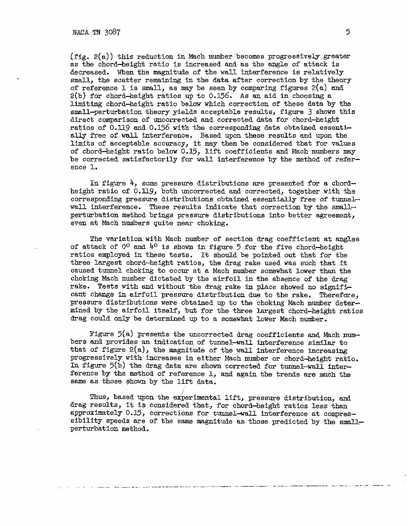
(fig. 2(a)) this reduction in Mach nuniberbecomes progressively greateras the chord+eight ratio is increased and as the angle of attack isdecreased. When the magnitude of the wall interference is relativelysmall.,the scatter remaining in the data after correction by the theoryof reference 1 is small, as maybe seenby comparing figures 2(a) and2(b) for chord+eight ratios up to 0.156. As an aid in choosing ali.mit~ chord+eight ratio below which correction of these databy thesmall-perturbationtheory y-ieldsacceptable results, figure 3 shows thisdirect comparison of uncorrected and corrected data for chord+ei,ghtratios of 0.13.9and 0.156 with the corresponding data obtained essenti-ally free of wall titerference. Based upon these results and upon thelimits of acceptable accuracy, it may thenbe considered that for valuesof chord-height ratio below 0.15, lift coefficients and Mach numbers maybe corrected satisfactorily for wall interference by the method of refer-ence 1.
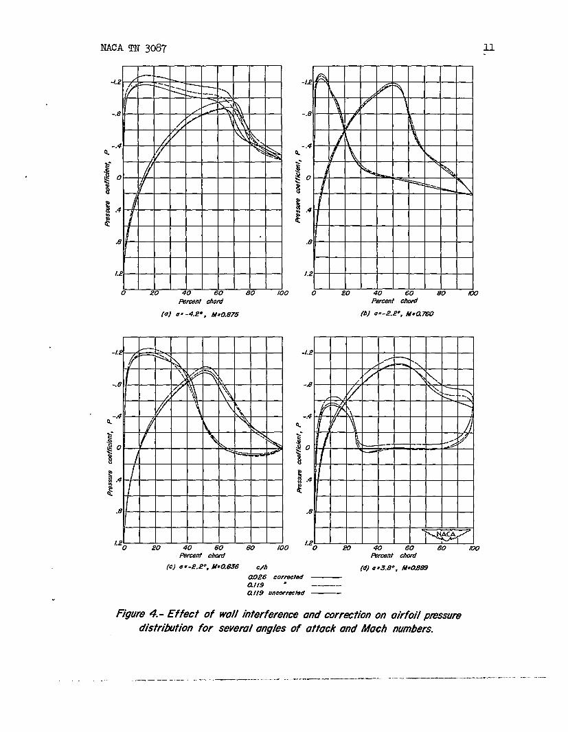
In figure 4, some pressure distributions are presented for a chord-height ratio of 0.119, both uncorrected and corrected, together with thecorresponding pressure distributions obtained essentially free of tunnel-wal.1interference. These results indicate that correction by the small-perturbation method brings pressure distributions into better agreement,even at Mach numbers quite near chok~.
The variation with Mach nwiber of section drag coefficient at anglesof attack of 0° and 4° is shown in figure 5 for the five chord-heightratios employed in these tests. It shouldbe pointed out that for thethree largest chord+eight ratios, the drag rake used was such that itcaused tumnel choking to occur at a Mach number somewhat lower than thechoking Mach number dictated by the airfoil in the absence of the dragrake. Tests with and without the drag rake in place showed no signifi-cant change in airfoil pressure distribution due to the rake. Therefore,pressure distribtiions were obtained up to the chokhg Mach number deter-mined by the airfoil itself, but for the three largest chord-height ratiosdrag colildonly be determined up to a somewhat lower &ch n~er.
Figure 5(a) presents the uncorrected drag coefficients and Mach n-hers and provides an indication of tunnel+nill interference similar tothat of figure 2(a), the magnitude of the wall interference increasingprogressively with increases in either Mach nuriberor chord-height ratio.In figure 5(b) the drag data are shown corrected for tunnel+all inter-ference by the method of reference 1, and again the trends are much thesame as those shown by the lift data.
Thus, based upon the e~erimental lift, pressure distribution, anddrag results, it is considered that, for chord-height ratios less thana~roximately 0.15, corrections for tunnel+mll taterference at compres-sibility speeds are of the same nmgnitude as those predicted by the small-perturbation method.
. ..—. --- . ———-- —- —----——--- —.—- -———- .- -—-————- — ———— - —-- -- —“-

6 NACA TN 3087
CONCLUSIONS
The results of an experimental investigation of wall interferencetwc+ihensiomal-flow, rectangular, closed-throatwind tunnelj
through a Mach nuniberre&e from ~.3 to O.9 emd a correspondingReynoldsnwiber range from 0.9 x 10⁶ to 1.8 x 10⁶, lead to the followimg concl~Sions:
1. For ratios of airfoil chord to tumel height up to approximately0.15, tunnel+all titerference is small and results corrected by thesmall~erturbation theory are in satisfactory agreement with correspon-dhg data obtained essentially interference free.
2. For larger values of chord-height ratio, wall interferencebecomes progressively greater and results corrected by this method becomeincreasingly questionable.
Ames Aeronatiical LaboratoryNational Advisory Committee for Aeronautics
Moffett Field, Calif., Ott. 1, 1953
RmmRmwEs
1. AUen, H. J., and Vincenti, W. G.: Wall Interference in a Two-Dimensional+low Wind Tumnel, with Consideration of the Effect dCompressibility. NACA Rep. 782, 1944.
2. Goldstein, S., and Young, A. D.: The Linear Perturbation Theory ofCompressible Flow, with Applications to Wtnd-tunnel Interference.R&M. No. 1909, British A.R.C., 1943.
3. Baranoff, A. V.: Tunnel Correction.forCompressible Subsonic Flow.NACA TM u62, 1947.
4. Pinkerton, R. M.: Calculated and Measured Pressure DistributionsOver the Midspan Section of the NACA kk12 Airfoil. NACA Rep. 563,1936.
5. Heaslet, Max. A.: Theoretical Iimestigation of Methods for ComputtngDrag from Wake Surveys at High Sfisonic Speeds. NACA WR-Wl, 1945.(For~rly NACA ARR 5C21.)
— -- —

NACA TN 3Q87
m,,, ,,, ,,,, ,, ’’,’’’’’’’’’’’’’” “’’’’’’’’”<
-—-—i=7%-
‘$
4?)CA= f21i9
?.,f,,~,,~’’’’’’’’’”” “’’’’’’’’”-
—-7
—~-—-—
1
>,,..~~~~~fl~~t~’t”” “’’’’’’’”4
-i--t
-— - ~. _—
(b) cA)= 0.156
—- T—~ % -—---Y_
7
of the A by 3-1/2-foot wind tunnel.
.._ ----- ..—-.— —--—--- ——-—- — ————.——

8 I?ACATN 3087
/.2
1.0
98
Q-
,6
.4
.2
0
-.2
-.4
I
== 40
.
/“
II I I I /“ r\
Q= 00
~ —
a= - 40
I I I
3 .$ .5 .6 .Mach number, M
c/h
0.026 —0.//9 .—— — ——
0,/56 —
0.357 ——
0.595———
(0)
2.- 14mt7tion
Uncozn9cA9d
of section
for severol
fm tine!- wall Min19mnce.
lift coefficient with Much
chord-height ratios.
.
.
— ..—

Iw’
a=4°
U=oo
a= .40. ~ k \
~ — ~ ~- — ~ —-~--
-.~
-1I
?
I.3 .4 .5 .6 .7 \
Mach number, M
c/h0.0260./19–––––––– ! \
0.156 /y ~0.357 —-
0.595 –-–
=s9=(b) Corrected tbr tunnel-wall interference.
F@ure 2.- Gorw’ude$.
———— -—. .——...__ -—
NACATN 3087
.
Q=4°
~=oo
, Q=- 40
.3 .4 ‘5 .6
Moth Number, M\
c/h t
0.026 corrected0.1 /9 “ .—. ———
\0.156 u —— \0.119 uncorrected0.156 “
\—— \ ‘\\ }
t I , 8
‘=5=
Figure 3.-Effect of wall interference and correction on the variation
of section i’ift coef ficienf with IWch number.
—..—— .—
NACA TN 3087 u.
-/.2
-. 8 .
\
\
k ‘“4
/ ‘
&
x
1.2
0 .?0 40 60 80 100Ruczmt OfIod
(0) 8=-4..?0, ff=o.875
-L?
-.8
4-.a.’
VI40 sA I I w I P&JI .-J-L-l__L-ziY I
~ $0k
% I
i /.4
FI
,8
1.20 20 40 60 80 100
Fwanfti AiY-#nt Chlwf
(c) a =-2.2”, hf=a636 c/h [d) 8=3.8”, ff=O.869
cUZ?6 COWOCtOd
alf9 “ –—–a f19 uncormctid —-
Figure 4.- Effect of wdl interference and awrdion on airfoil pmssumo’istri~ion for seved angles of ottack and Much numbers.
— -. .. ..— -—------——— —. —--- –——-.—-—— — .-.. —————. ——.-—----- -—–—---

32 NACA TN 3087
J4 I
c/h i’ //
0.026
o.f19 ‘—/’ /
./2 I0./56 — /
0.357 / /I
0.595 ——/’ [
Jo/
%i“
II Ic1 /
I ‘ //‘& .08 / //
i?.041 I I I I 1 I 11 1 1 I r 1 f , ,II :1/# I I A
0
Mach number, M
(o) Uncom?cted hr tunnel- WOII i-rfen?nce.
Figun? 5. - Vuriotion of section dmg c0eftXc18nt wh% Mach numberfor S8verol chord- height @iOS.
.
,
.
————

J,
./i
.1(
c/h
0.0260.//9 – – /0.156 — /
0.357 .— // 40.595
I—-—I ./
/
Q=40
a =00-- —_ _ ___ _—— ———— — ~
P.3 .4 5 6 .7 .8
Mach number, M
(b) Corrected for tunnel- well Intert%n?nce.
Figure 5.- Concltii?d.
NACA-Lm@q -12-15-53- l~i)
—.._ —. ——. , . .— .__. “._ .. —_: ——.
//z/’
&7
1
——— —