technical specifi cation technische spezifi kation...
TRANSCRIPT
Technical Specifi cation Technische Spezifi kation Spécifi cations techniques Specifi che tecniche Especifi caciones técnicas
Power supply Spannungsversorgung Alimentation Alimentazione Alimentación
24 V DC from the base unit (PELV / SELV) 24 V DC vom Hauptgerät (PELV / SELV) 24 V c.c. d’un module de base (PELV / SELV) 24V CC desde la unidad base (PELV / SELV) 24V c.c. dall’unità di base (PELV / SELV)
Power consumption Leistungsverbrauch Consommation Consumo energetico Consumo eléctrico
2 W 2 W 2 W 2 W 2 W
Safety inputs Schutzeingänge Contacts d’entrée de sécurité Entrate di sicurezza Entradas de seguridad
1 N.C., 2 N.C. or 3 N.C. or mat 1 N.C., 2 N.C. oder 3 N.C. oder Sicherheitsmatte 1, 2 ou 3 N.F. ou tapis 1 N.C., 2 N.C. ó 3 N.C. o alfombra 1 N.C., 2 N.C. o 3 N.C. o pedana
Input simultaneity Eingangsgleichzeitigkeit Simultanéité des entrées Simultaneità d’entrata Simultaneidad de entrada
Infi nite Unbegrenzt Infi nie Infi nita Infi nita
Max. allowable input resistance Max. zulässiger Eingangswiderstand Résistance max. d’entrée Max resistenza d’entrata permissibile Resistencia máxima de entrada permitida
900 ohms 900 Ohm 900 ohms 900 ohms 900 ohmios
Indication LED’s Anzeige-LEDs DEL d’état LED di indicazione LEDs indicadores
Green = Input 1 closed
Red = Input 1 open
Green = Input 2 closed
Red = Input 2 open
Grün = Eingang 1 geschlossen
Rot = Eingang 1 geöff net
Grün = Eingang 2 geschlossen
Rot = Eingang 2 geöff net
Vert = Entrée 1 fermée
Rouge = Entrée 1 ouverte
Vert = Entrée 2 fermée
Rouge = Entrée 2 ouverte
Verde = Entrata 1 chiusa
Rosso = Entrata 1 aperta
Verde = Entrata 2 chiusa
Rosso = Entrata 2 aperta
Verde = Entrada 1 cerrada
Rojo = Entrada 1 abierta
Verde = Entrada 2 cerrada
Rojo = Entrada 2 abierta
Impulse withstand voltage Prüfspannung Tension impulsionnelle admise IMassima tensione d’impulso sosten. Voltaje impulsivo no disruptivo
2500 V 2500 V 2500 V 2500 V 2500 V
Pollution degree Verschmutzungsgrad Indice de pollution Grado di contaminazione Grado de contaminación
2 2 2 2 2
Installation group Installationsgruppe Groupe de montage Gruppo d’installazione Grupo de instalación
Overvoltage catagory III, VDE 0110-1 Überspannungskategorie III, VDE 0110-1 Catègorie de surtension,III, VDE 0110-1 Categoria di sovratensione III, VDE 0110-1 Categoría de sobrevoltaje III, VDE 0110-1
Operating temperature Betriebstemperatur Température de service Temperatura d’esercizio Temperatura operativa
-5 °C .... +55 °C (+23 °F .... 131 °F) -5 °C .... +55 °C (+23 °F .... 131 °F) -5 °C .... +55 °C (+23 °F .... 131 °F) -5 °C .... +55 °C (+23 °F .... 131 °F) -5 °C .... +55 °C (+23 °F .... 131 °F)
Humidity Feuchtigkeit Humidité Umidità Humedad
90% RH 90% RH 90% RH 90% RH 90% RH
Enclosure protection Gehäuseschutz Indice de protection enceinte Protezione chiusura Protección envolvente
IP40 (NEMA 1) IP40 (NEMA 1) IP40 (NEMA 1) IP40 (NEMA 1) IP40 (NEMA 1)
Terminal protection Klemmenschutz Protection aux bornes Protezione terminali Protección terminales
IP20 IP20 IP20 IP20 IP20
Conductor size Leiterquerschnitt Diamètre conducteur Dimensioni conduttori Diámetro del conductor
0.2 - 2.5 mm2 (24 -12 AWG) 0.2 - 2.5 mm2 (24 -12 AWG) 0.2 - 2.5 mm2 (24 -12 AWG) 0.2 - 2.5 mm2 (24 -12 AWG) 0.2 - 2.5 mm2 (24 -12 AWG)
Torque settings - terminal screws Drehmomentwerte - Klemmenschrauben Couple des vis de bornes Tarature di coppia - viti terminale Valores de par - tornillos de los terminales
0.6 Nm - 0.8 Nm (5 - 7 lb•in) 0.6 Nm - 0.8 Nm (5 - 7 lb•in) 0.6 Nm - 0.8 Nm (5 - 7 lb•in) 0.6 Nm - 0.8 Nm (5 - 7 lb•in) 0.6 Nm - 0.8 Nm (5 - 7 lb•in)
Case material Gehäusematerial Composition du boîtier Materiale cassa Material de la carcasa
Polyamide PA 6.6 Polyamid PA 6.6 Polyamide PA 6.6 Poliammide PA 6.6 Poliamida PA 6.6
Mounting Befestigung Montage Supporto Montaje
35 mm DIN rail in enclosure to a min of IP54 35 mm DIN-Schiene in Einbaugehäuse nach mind IP54 Rail DIN de 35 mm dans un boîtier IP54 minimum Rotaia DIN 35 mm in cabina con IP54 al minimo Riel DIN de 35 mm en envolvente a un mín. de IP54
Weight Gewicht Poids Peso Peso
95 g (0.21 lb) 95 g (0.21 lb) 95 g (0.21 lb) 95 g (0.21 lb) 95 g (0.21 lb)
Vibration Vibration Vibrations Vibrazioni Vibración
10-55 Hz, 0.35 mm 10-55 Hz, 0.35 mm 10-55 Hz, 0.35 mm 10-55 Hz, 0.35 mm 10-55 Hz, 0.35 mm
Minotaur MSR221PMonitoring Safety Relay - Installation Instructions
Sicherheitsrelais - Installationsanleitung
Relais de sécurité de surveillance - Notice d’installation
Relé di monitoraggio di sicurezza - Istruzioni per l’installazione
Relé de seguridad de monitorización - Instrucciones de instalación
10000176988 ver 00, Dwg. No: 95302175, EO: 0329, Issue 2, April 2011
This device is intended to be part of the safety
related control system of a machine.
SAFETY NOTESBefore installation, a risk assessment
should be performed to determine
whether the specifi cations of this device
are suitable for all foreseeable
operational and environmental
characteristics of the machine to which it
is to be fi tted. At regular intervals during
the life of the machine check whether
the characteristics foreseen remain valid.
Danger of serious injuries!
Misuse can result in malfunction.
The device may only be started up, assembled
or retrofi tted by an authorized and trained personnel.
Installation must be in accordance with the
following steps.
Danger of serious injuries!
Incorrect installation or manipulation can
result in serious injuries.
Do not defeat, tamper, remove or bypass
this unit.
Responsibility cannot be accepted for
a failure of this device if the procedures
given in this sheet are not implemented
or if it is used outside the recommended
specifi cations in this sheet.
NOTE: The safety inputs of these products are
described as normally closed (N.C.), ie. with the
guard closed, actuator in place (where relevant) and
the machine able to be started.
Exposure to shock and/or vibration in excess
of those stated in IEC 60068 part: 2-6/7 should
be prevented. Adherence to the recommended
inspection and maintenance instructions forms part
of the warranty.
NOTE: All information comply with state of this
publication. Subject to change without notice.
REPAIRIf there is any malfunction or damage, no
attempts or repair should be made. The
unit should be replaced before machine
operation is allowed.
DO NOT DISMANTLE THE UNIT.
Rockwell Automation hereby declares that
MSR221P is in conformity with Directive(s)
2004/108/EC, 2006/42/EC as specifi ed in the
Declaration of Conformity available from www.
rockwellautomation.com/ products/ certifi cation
All four inputs of the MSR221P must be at 24 V DC
levels to confi rm its operational status to the basic
module over the system bus. The safety contacts
can be closed (relay energised) only if all inputs of
the complete system are activated (green LED on).
If an emergency stop input device deactivates one
input, the safety contacts open (relay deenergised)
immediately. With positive input signals and dual
channel connection of emergency stop switching
devices, cross-fault monitoring is not done by the
MSR221P, since this function is usually integrated
into 2-channel light curtains and scanners with
semiconductor outputs. Since all inputs of the
system are interrogated continuously, unused inputs
of the MSR221P must be connected directly to the
+24 V DC supply circuit.
Dieses Gerät ist als Teil des sicherheitsrelevanten
Kontrollsystems einer Maschine vorgesehen.
ALLGEMEINE SICHERHEITSHINWEISEFür die Maschine, in die dieses Gerät
eingebaut wird, muss eine Risikobeurtei-
lung durchgeführt werden. Anhand der
Risikobeurteilung muss geprüft werden,
ob die Spezifi kationen dieses Gerätes
den Betriebs- und Umgebungsbedin-
gungen der Maschine entsprechen.
In regelmäßigen Abständen, während
der Lebensdauer der Maschine, ist zu
überprüfen, ob die vorhergesehenen
Spezifi kationen weiterhin gültig sind.
Gefahr von schweren Verletzungen!
Durch unsachgemäße Montage kann es zu
Fehlfunktionen kommen.
Die Montage darf nur durch fachlich qualifi zier-
tes Personal erfolgen.
Die nachfolgend beschriebenen Arbeitsschritte
müssen eingehalten werden.
Gefahr von schweren Verletzungen!
Durch unsachgemäßen Gebrauch kann es zu
schweren Verletzungen kommen.
Das Gerät niemals überbrücken.
Es kann keinerlei Verantwortung für ein
Versagen dieses Gerätes übernommen
werden, wenn die in diesem Schriftblatt
gegebenen Verfahrensweisen nicht imple-
mentiert wurden, oder wenn sie außerhalb
der auf diesem Schriftblatt empfohlenen
Spezifi kationen verwendet werden.
HINWEIS: Die Sicherheitskontakte der Schutzvor-
richtung sind als Ruhekontakte (N.C.) beschrieben,
d.h. bei geschlossener Schutzvorrichtung sind die
Betätigungselemente in Position (falls zutreff end)
und die Maschine ist startfähig.
Eine Aussetzung an Stoßbelastungen und/oder
Vibrationen, die über den in IEC 60068, Teil 2-6/7 an-
gegebenen Werten liegen, sollte verhindert werden.
Die Einhaltung der empfohlenen Inspektions- und
Wartungsvorschriften ist Teil der Garantie.
HINWEIS: Alle Angaben entsprechen dem
aktuellen Stand der Veröff entlichung. Änderungen
behalten wir uns jederzeit vor.
REPARATURBei Fehlfunktion oder Beschädigung
dürfen keine Reparaturversuche unter-
nommen werden. Das Gerät muss er-
setzt werden, bevor ein weiterer Betrieb
der Maschine zugelassen wird.
DAS GERÄT DARF NICHT AUSEINAN-DERGEBAUT WERDEN.
Hiermit erklärt Rockwell Automation, dass
MSR221P wie in der Konformitätserklärung
angegeben, den Richtlinien 2004/108/EG,
2006/42/EG genügt, erhältlich von www.
rockwellautomation.com/products/certifi cation
Liegen an allen vier Eingangskreisen des MSR221P
+24 V DC an, so wird die Freigabemeldung über das
Flachbandkabel zum Basismodul übertragen. Erst
wenn von allen Eingängen des Systems die Freigabe
vorliegt, können die Sicherheitskontakte geschlos-
sen werden. Wird ein Not-Halt Element betätigt, so
dass der entsprechende Eingang spannungslos wird,
öff net das Basismodul sofort die Sicherheitskon-
takte. Die Ansteuerung der MSR221P Eingänge mit
positiven Eingangssignalen bedingt, dass bei einer
zweikanaligen Beschaltung mit Not-Halt Tastern etc.
keine Querschlussüberwachung erfolgt. Zweikanali-
ge Sicherheitslichtgitter oder Scanner haben diese
Funktion jedoch üblicherweise integriert. Da ständig
alle vorhandenen Eingänge des Systems abgefragt
werden, müssen auch unbenutzte Eingänge beschal-
tet werden (+24 V auf freie Eingangsklemmen der
Lichtgittermodule legen).
Ce dispositif est étudié pour être incorporé dans le
système de contrôle pour la sécurité d’une machine.
CONSIGNES DE SÉCURITÉAvant l’installation, on doit eff ectuer une
évaluation des risques pour déterminer
si les spécifi cations de ce dispositif sont
appropriées pour toutes les caractéris-
tiques de service et du milieu d’utilisation
prévues pour la machine sur laquelle il
sera monté. Vérifi er, à des échéances ré-
gulières au cours de la vie de la machine,
que les caractéristiques prévues soient
toujours valables.
Danger de blessures graves !
Une mauvaise utilisation peut entraîner un
mauvais fonctionnement.
Seul du personnel formé et autorisé a le droit de
mettre en service, assembler ou monter l‘appareil.
L‘installation doit être eff ectuée.
Danger de blessures graves !
Une mauvaise installation ou une manipu-
lation incorrecte peut entraîner de graves
blessures.
Ne pas altérer la confi guration, modifi er, retirer
ou contourner cette unité.
Toute responsabilité est déclinée pour
les défaillances de cet appareil si les pro-
cédures décrites dans la présente notice
ne sont pas appliquées ou si l’appareil est
utilisé hors des spécifi cations recomman-
dées dans cette même notice.
REMARQUE : Les entreés de sécurité de ces
produits sont décrits comme normalement fermés
(N.F), c’est-à-dire lorsque la protection est fermée,
l’actionneur est en place (si applicable) et la machine
est en état de démarrer.
Eviter toute exposition à des chocs et/ou des
vibrations supérieurs à ceux qui sont spécifi és
dans la norme IEC 60068 part 2-6/7. Le respect des
instructions relatives à l’inspection, au contrôle et à
l’entretien de cet appareil rentre dans l’application
de la garantie.
REMARQUE : Toutes les indications fournies
correspondent aux connaissances actuelles au mo-
ment de la publication. Sous réserve de modifi cation
à tout moment.
RÉPARATIONEn cas de défaut de fonctionnement
ou d’endommagement, ne jamais
essayer de réparer le dispositif. Il doit être
remplacé avant de remettre la machine
en service.
NE JAMAIS DÉMONTER LE DISPOSITIF.
Rockwell Automation déclare par la
présente que le MSR221P est conforme aux
directives 2004/108/EC, 2006/42/EC telles
que spécifi ées dans la déclaration de conformité
consultable et disponible sur le lien www.
rockwellautomation.com/products/certifi cation
Les quatre entrées du MSR221P doivent être alimen-
tées en 24 V c.c. pour confi rmer son état de service au
module de base grâce au bus interne. Les contacts
de sécurité peuvent uniquement être fermés
(relais excités) si toutes les entrées du système sont
activées (DEL verte allumée). Si un dispositif d‘arrêt
d‘urgence désactive une entrée, les contacts de sé-
curité s‘ouvrent (relais désexcités) immédiatement.
Avec des signaux d‘entrée positifs et la connexion
bi-canal des dispositifs d‘arrêt d‘urgence, le contrôle
des défaillances entre circuit n‘est pas assuré par le
MSR221puisque cette fonction est généralement
intégrée aux barrières photoélectriques bicanal et
aux scanners à sorties à semi-conducteur. Puisque
toutes les sorties du système sont continuellement
interrogées, les entrées inutilisées du MSR221
doivent être directement connectées au circuit
d‘alimentation +24 V c.c.
Questo dispositivo fa parte del sistema di comando
relativo alla sicurezza di una macchina.
ISTRUZIONI DI SICUREZZAPrima dell’installazione occorre eseguire
una valutazione die rischi per stabilire se
le specifi che del dispositivo siano adatte
per tutte le caratteristiche operative ed
ambientali che si possano anticipare per
la macchina su cui deve essere montato.
Periodicamente durante la durata utile
della macchina occorre verifi care se le
caratteristiche previste rimangono valide.
Pericolo di lesioni gravi!
Un uso scorretto può causare un funzionamento
anomalo.
Il dispositivo può essere soltanto avviato, montato,
o aggiornato da personale autorizzato e addestrato.
L‘installazione deve essere conforme alle
seguenti fasi.
Pericolo di lesioni gravi!
Una installazione o un trattamento scorretti
possono causare lesioni gravi.
Non vanifi care, manomettere, rimuovere o
bypassare questa.
Si declina ogni responsabilità per il
mancato funzionamento del presente
dispositivo se le procedure indicate in
questa scheda non sono messe in atto o
se il dispositivo viene utilizzato in modo
che esula dalle specifi che consigliate in
questa scheda.
NB: Le entrate di sicurezza di questi prodotti sono de-
scritte come normalmente chiuse (NC), vale a dire con
la protezione chiusa, l’attuatore in posizione (ove sia
pertinente) e la macchina in grado di essere avviata.
Occorre evitare l’esposizione ad impatti e/o a vibrazioni
che eccedano quelli indicati nella specifi ca CEI 60068
parte: 2-6/7. L’osservanza delle istruzioni di ispezione
e di manutenzione consigliate formano parte della
garanzia.
NB: Tutte le indicazioni corrispondono allo stato
attuale della pubblicazione. Ci riserviamo il diritto di
apportare modifi che in qualsiasi momento.
RIPARAZIONEIn caso di funzionamento anomalo o di
danno, non si deve cercare di eff ettuare
una riparazione. L’unità deve essere
sostituita prima di ricominciare a far
funzionare la macchina. NON SMONTARE L’UNITÀ.
Con la presente Rockwell Automation
dichiara che MSR221P è conforme alle
Direttive 2004/108/EC, 2006/42/EC come
specifi cate nella Dichiarazione di conformità
disponibile da www.
rockwellautomation.com/products/certifi cation
Tutte le quattro entrate del MSR221P devono essere
alimentate a 24 V c.c. per confermare il suo stato
di servizio al modulo di base sul bus del sistema.
I contatti di sicurezza possono essere chiusi (relè
sotto tensione) soltanto se tutte le entrate del
sistema completo sono attivate (LED verde illumi-
nato). Se un dispositivo di arresto di emergenza
disattiva un‘entrata, i contatti di sicurezza si aprono
immediatamente (relè disattivato). Con segnali
positivi di entrata e la connessione a canale doppio
dei dispositivi d‘arresto di emergenza, il controllo
incrociato dei guasti non è eseguito dal MSR221P,
in quanto tale funzione è di solito integrata nelle
barriere fotoelettriche a due canali e negli scanner
con uscite a semiconduttore. Poiché tutte le entrate
del sistema sono interrogate in continuazione, le
entrate non utilizzate del MSR221P devono essere
connesse direttamente al circuito di alimentazione
di +24 V c.c.
Este dispositivo está concebido como parte
integrante del sistema de control de seguridad
correspondiente de una máquina.
INDICACIONES DE SEGURIDADAntes de proceder a la instalación,
deberán realizarse estudios de riesgos
que determinen la idoneidad de las
especifi caciones de este dispositivo
para todas las características operativas
y ambientales previsibles de la máquina
donde va a ser colocado. Revise regu-
larmente la máquina para cerciorarse de
que las características previsibles siguen
siendo válidas.
Peligro de lesiones graves!
Un uso incorrecto puede derivar en fallos de
funcionamiento.
El dispositivo sólo podrá arrancar, montarse o adap-
tarse por personal autorizado y debidamente capacitado.
La instalación deberá realizarse según los pasos
que fi guran a continuación.
Peligro de lesiones graves!
La incorrecta instalación o manipulación de
este producto puede producir lesiones graves.
No malogre, manipule, retire ni desvíe esta
unidad unità.
Se declina cualquier tipo de responsabi-
lidad por fallos en el funcionamiento de
este dispositivo resultantes del incumpli-
miento de las instrucciones expuestas en
esta hoja o del uso ajeno a las especifi ca-
ciones aquí recomendadas.
NOTA: Los contactos de entrada de estos productos
se describen como normalmente cerrados (o N.C.),
es decir, con el protector cerrado, el accionador en
su lugar (si procede) y la máquina en condiciones
de arrancar.
Deberá evitarse la exposición a golpes o vibraciones
superiores a los niveles indicados en la CEI 60068:
2-6/7. El cumplimiento de las instrucciones de
inspección y mantenimiento recomendadas forma
parte de la garantía.
NOTA: Todos los datos se corresponden con la fecha
de publicación. Nos reservamos el derecho a introducir
cambios sin previo aviso.
REPARACIÓNSi hubiera algún defecto o avería, no
intente repararlos. Sustituya la unidad
antes de autorizar el funcionamiento de
la máquina.
NO DESMONTE LA UNIDAD.
Rockwell Automation declara por la
presente que el MSR221P cumple las
Directivas 2004/108/EC, 2006/42/ EC según
se especifi ca en la Declaración de conformidad. Para
obtenerla, visite www.
rockwellautomation.com/products/certifi cation
Las cuatro entradas del MSR221P deben tener una
alimentación de 24 VDC para confi rmar su estado
operativo al modelo básico a través del bus de
sistema. Los contactos de seguridad pueden cerrarse
(relé activado) sólo si se activan todas las entradas
de todo el sistema (LED verde encendido). Si un
dispositivo de entrada de parada de emergencia
desactiva una entrada, los contactos de seguridad
se abrirán inmediatamente (relé desactivado). Con
señales de entrada positivas y conexión de canal
doble de dispositivos de conmutación de parada
de emergencia, el MSR221P no realiza la monitori-
zación de fallos cruzados ya que esta función suele
integrarse en cortinas fotoeléctricas y escáneres
de dos canales con salidas de semiconductor.
Como todas las entradas del sistema se interrogan
constantemente, las entradas no usadas del
MSR221P deben conectarse directamente al circuito
de alimentación de +24 VCC.
English (original)
Declaration of Conformity Konformitätserklärung Déclaration de Conformité Dichiarazione di conformità Declaración de conformidad
Deutsch (original) Français (traduction) Italiano (traduzione) Español (traducción)
WARNING WARNUNG AVERTISSEMENT AVVERTENZA! ADVERTENCIA!
AVERTISSEMENT AVVERTENZA! ADVERTENCIA!WARNUNGWARNING
10000176988 ver 00, Dwg. No: 95302175, Issue 2, April 2011 Copyright ©2011 Rockwell Automation, Inc. All Rights Reserved. Printed in Germany.
Functional Description Funktionsbeschreibung Description fonctionnelle Descrizione funzionale Descripción funcional
Dimensions / Abmessungen / Dimensions / Dimensioni / Dimensiones
Through the intermodule bus, the basic
module ascertains the confi guration as
well as the switching condition of the
inputs of the expansion modules. The
open bus interface connector of the last
module must therefore have a
terminating plug. The “READY” status of
each input is indicated by a
corresponding green LED. As soon as
an emergency stop command or a fault
closes an input, the basic module opens
the safety contact, and instead of the
green, the red input LED lights up.
The status of this input can be
transmitted to a supervisory system
(PLC or computer), and the cause and
time of the tripping recorded. A quick
diagnosis of the cause of the emergency
stop occurrence is therefore possible and
increases system safety, while avoiding
unnecessary down time.
Über die Datenleitung ermittelt das
Basismodul die Konfi guration sowie
den Schaltzustand der Eingänge, wobei
die off ene Schnittstelle des Endgerätes
immer mit einem Abschlussstecker ver-
sehen werden muss. Die Betriebsbereit-
schaft der Eingänge wird durch die grüne
LED, die jedem Eingang zugeordnet ist,
signalisiert. Sobald ein Eingang durch
einen Not-Halt Befehl oder eine Störung
eine Systemabschaltung herbeiführt,
leuchtet statt der grünen die rote
Eingangs-LED. Außerdem kann der
betroff ene Eingang als Auslöseursache
an eine Auswerteeinheit übertragen
und protokolliert werden. So ist eine
schnelle Diagnose der Not-Halt Ursache
zur Erhöhung der Anlagensicherheit und
Vermeidung von unnötigenStillstands-
zeiten möglich.
Grâce au bus inter-module, le module
de base vérifi e la confi guration ainsi que
l‘état de commutation des entrées des
modules d‘extension. Le connecteur ou-
vert d‘interface à bus du dernier module
doit donc prévoir une prise terminale.
L‘état „PRET“ de chaque entrée est indi-
qué par une DEL verte particulière. Dès
qu‘une commande d‘arrêt d‘urgence
ou une défaillance ferme une entrée,
le module de base ouvre le contact de
sécurité et la DEL d‘entrée rouge s‘allume
à la place de la DEL verte. L‘état de cette
entrée peut être transmis à un système
de surveillance (API ou PC) pour enregist-
rer la cause et l‘heure de la disjonction.
Un diagnostic rapide de la cause
de l‘arrêt d‘urgence est ainsi prévu,
optimisant la sûreté du système tout en
éliminant les temps d‘arrêt inutiles.
Tramite il bus intermodulo, il modulo di
base verifi ca la confi gurazione ed allo
stesso tempo la condizione di commuta-
zione delle entrate dei moduli di espan-
sione. Il connettore aperto d‘interfaccia
al bus dell‘ultimo modulo deve perciò
avere una spina di terminazione. Lo stato
„READY“ di ciascuna entrata è indicato da
un LED verde corrispondente. Appena
un comando di arresto di emergenza o
un guasto chiude un‘entrata, il modulo
di base apre il contatto di sicurezza e
invece del LED verde, si illumina quello
rosso. Lo stato di questa entrata può
essere trasmesso ad un sistema di super-
visione (PLC o elaboratore) per registrare
la causa e l‘ora dello scatto. È perciò
possibile eff ettuare una diagnosi rapida
della causa dell‘attivazione dell‘arresto
di emergenza e migliorare la sicurezza
del sistema, evitando allo stesso tempo
tempi morti non necessari.
A través del bus intermódulos, el modulo
básico determina la confi guración y
el estado de conmutación de las
entradas de los módulos de extensión. El
conector de interfaz de bus abierto del
ultimo modulo debe por ello disponer
de un enchufe terminal. El estado de
preparado „READY“ de cada entrada se
indica en verde en el correspondiente
LED bicolor. En cuanto una orden de
parada de emergencia o un fallo cierra
una entrada, el módulo básico abre el
contacto de seguridad y se enciende el
LED rojo de entrada en lugar del verde.
El estado de esta entrada puede trans-
mitirse a un sistema de supervisión (PLC
u ordenador) y se registrará la causa y la
hora del disparo. Se posibilita así realizar
un rápido diagnóstico de la causa de
la parada de emergencia y aumentar la
seguridad del sistema evitando innece-
sarios tiempos de inactividad.
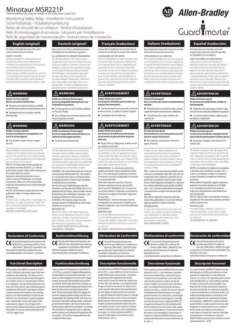
For the system to function, inputs at
terminals S12, S32, S42 and S62 must be
24 V DC levels. If only one light curtain
is connected, the inputs to the other
channel must be either emergency stop
switches (as shown in the circuit examp-
le), or these inputs must be connected
directly to the +24 V DC line. The signal
inputs and 24 V DC power supply must
have a common return path.
Zur Systemfreigabe müssen S12, S32,
S42 und S62 an 24 V DC Pegel liegen.
Wird nur ein Lichtgitter angeschlossen,
so muss der andere Eingang entweder
mit einem Not-Halt Element gemäß
Schaltungsbeispiel beschaltet werden
oder die Eingänge werden fest an +24 V
DC angeschlossen. Die Signaleingänge
und die 24 V DC Spannungsversorgung
müssen einen gemeinsamen Rücklauf
haben.
Pour que le système fonctionne, les
entrées aux bornes S12, S32, S42 et S62
doivent être des signaux de 24 V c.c. Si
une seule barrière photoélectrique est
connectée, les entrées de l‘autre canal
doivent être soit des commutateurs
d‘arrêt d‘urgence (tel qu‘illustré dans
l‘exemple de circuit), soit directement
connectées à l‘alimentation +24 V c.c.
Les entrées de signal et l‘alimentation
24 V c.c. doivent avoir un canal de retour
commun.
Per che il sistema possa funzionare, le
entrate ai terminali S12, S32, S42 e S62
devono essere a livelli di 24 V c.c. Se è
connessauna sola barriera fotoelettrica,
le entrate all‘altro canaledevono essere
interruttori di arresto di emergenza
(come illustrato nell‘esempio del circui-
to), o queste entratedevono essere con-
nesse direttamente alla linea +24 V c.c.
Le entrate dei segnali e l‘alimentazione
di 24 V c.c. devonoavere un percorso di
ritorno comune.
Para que funcione el sistema, las entra-
das a los terminales S12, S32, S42 y S62
deben ser de 24 VCC. Si sólo se conecta
una cortina fotoeléctrica, las entradas al
otro canal sólo pueden ser interruptores
de parada de emergencia (como muest-
ra el circuito de ejemplo), o dichas entra-
das deben conectarse directamente a la
línea de +24 VCC. Las entradas de señal
y la alimentación de 24 VCC deben tener
una vía de retorno común.
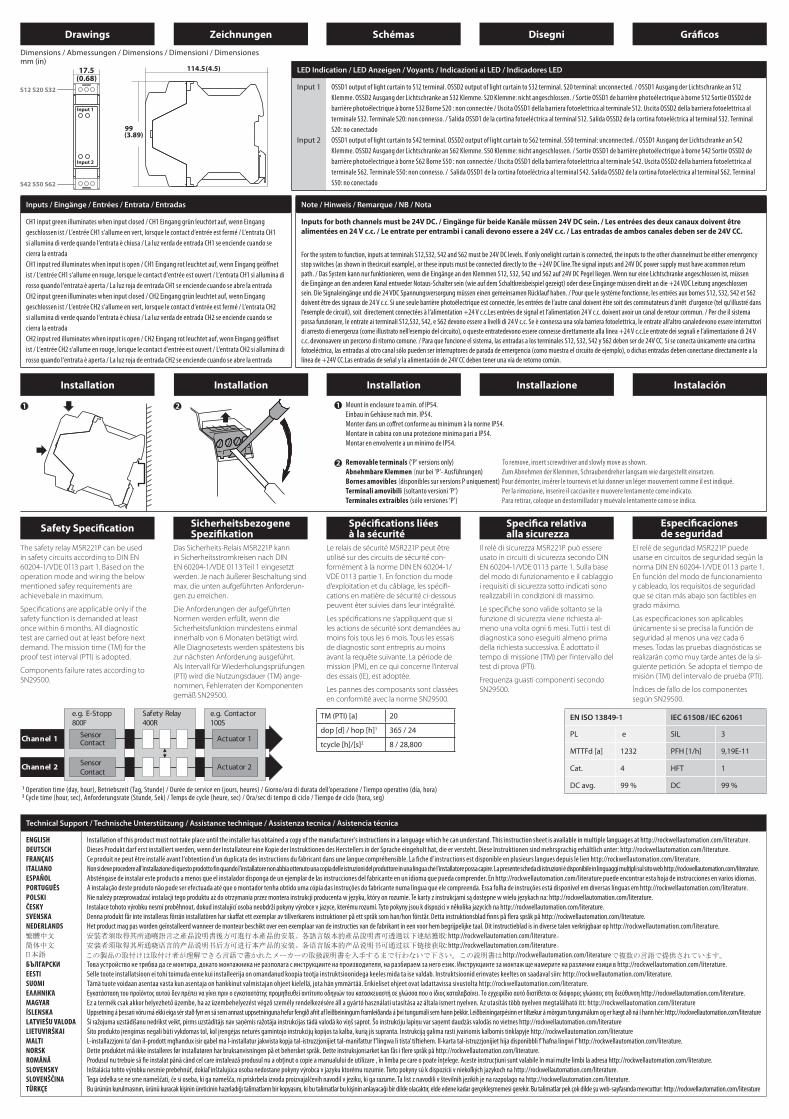
The safety relay MSR221P can be used
in safety circuits according to DIN EN
60204-1/VDE 0113 part 1. Based on the
operation mode and wiring the below
mentioned safey requirements are
achievebale in maximum.
Specifi cations are applicable only if the
safety function is demanded at least
once within 6 months. All diagnostic
test are carried out at least before next
demand. The mission time (TM) for the
proof test interval (PTI) is adopted.
Components failure rates according to
SN29500.
Das Sicherheits-Relais MSR221P kann
in Sicherheitsstromkreisen nach DIN
EN 60204-1/VDE 0113 Teil 1 eingesetzt
werden. Je nach äußerer Beschaltung sind
max. die unten aufgeführten Anforderun-
gen zu erreichen.
Die Anforderungen der aufgeführten
Normen werden erfüllt, wenn die
Sicherheitsfunktion mindestens einmal
innerhalb von 6 Monaten betätigt wird.
Alle Diagnosetests werden spätestens bis
zur nächsten Anforderung ausgeführt.
Als Intervall für Wiederholungsprüfungen
(PTI) wird die Nutzungsdauer (TM) ange-
nommen, Fehlerraten der Komponenten
gemäß SN29500.
Le relais de sécurité MSR221P peut être
utilisé sur des circuits de sécurité con-
formément à la norme DIN EN 60204-1/
VDE 0113 partie 1. En fonction du mode
d‘exploitation et du câblage, les spécifi -
cations en matière de sécurité ci-dessous
peuvent êter suivies dans leur intégralité.
Les spécifi cations ne s‘appliquent que si
les actions de sécurité sont demandées au
moins fois tous les 6 mois. Tous les essais
de diagnostic sont entrepris au moins
avant la requête suivante. La période de
mission (PM), en ce qui concerne l‘interval
des essais (IE), est adoptée.
Les pannes des composants sont classées
en conformité avec la norme SN29500.
Il relè di sicurezza MSR221P può essere
usato in circuiti di sicurezza secondo DIN
EN 60204-1/VDE 0113 parte 1. Sulla base
del modo di funzionamento e il cablaggio
i requisiti di sicurezza sotto indicati sono
realizzabili in condizioni di massimo.
Le specifi che sono valide soltanto se la
funzione di sicurezza viene richiesta al-
meno una volta ogni 6 mesi. Tutti i test di
diagnostica sono eseguiti almeno prima
della richiesta successiva. È adottato il
tempo di missione (TM) per l‘intervallo del
test di prova (PTI).
Frequenza guasti componenti secondo
SN29500.
El relé de seguridad MSR221P puede
usarse en circuitos de seguridad según la
norma DIN EN 60204-1/VDE 0113 parte 1.
En función del modo de funcionamiento
y cableado, los requisitos de seguridad
que se citan más abajo son factibles en
grado máximo.
Las especifi caciones son aplicables
únicamente si se precisa la función de
seguridad al menos una vez cada 6
meses. Todas las pruebas diagnósticas se
realizarán como muy tarde antes de la si-
guiente petición. Se adopta el tiempo de
misión (TM) del intervalo de prueba (PTI).
Índices de fallo de los componentes
según SN29500.
Drawings
Drawings
Zeichnungen
Zeichnungen
Schémas
Schémas
Disegni
Disegni
Gráfi cos
Gráfi cos
Circuit Diagram / Anschlussdiagramm / Schema des connexions Diagramma circuitale / Diagrama de circuitos
Connections / Anschlüsse / Connexions / Connessioni / Conexiones
S12, S20, S32, S42, S50, S62 Safety input (N.C.) / Sicherheitseingang (Ruhekontakt) / Entrée de sécurité (N/F) / Entrata di sicurezza (NC) / Entrada de seguridad (N.C.)
Technical Support / Technische Unterstützung / Assistance technique / Assistenza tecnica / Asistencia técnica
ENGLISH
DEUTSCH
FRANÇAIS
ITALIANO
ESPAÑOL
PORTUGUÊS
POLSKI
ČESKY
SVENSKA
NEDERLANDS
БЪЛГАРСКИ
EESTI
SUOMI
ΕΛΛΗΝΙΚΆ
MAGYAR
ÍSLENSKA
LATVIEŠU VALODA
LIETUVIRŠKAI
MALTI
NORSK
ROMÂNĂ
SLOVENSKY
SLOVENŠČINA
TÜRKÇE
Installation of this product must not take place until the installer has obtained a copy of the manufacturer’s instructions in a language which he can understand. This instruction sheet is available in multiple languages at http://rockwellautomation.com/literature.
Dieses Produkt darf erst installiert werden, wenn der Installateur eine Kopie der Instruktionen des Herstellers in der Sprache eingeholt hat, die er versteht. Diese Instruktionen sind mehrsprachig erhältlich unter: http://rockwellautomation.com/literature.
Ce produit ne peut être installé avant l’obtention d’un duplicata des instructions du fabricant dans une langue compréhensible. La fi che d’instructions est disponible en plusieurs langues depuis le lien http://rockwellautomation.com/literature.
Non si deve procedere all’installazione di questo prodotto fin quando l’installatore non abbia ottenuto una copia delle istruzioni del produttore in una lingua che l’installatore possa capire. La presente scheda di istruzioni è disponibile in linguaggi multipli sul sito web http://rockwellautomation.com/literature.
Absténgase de instalar este producto a menos que el instalador disponga de un ejemplar de las instrucciones del fabricante en un idioma que pueda comprender. En http://rockwellautomation.com/literature puede encontrar esta hoja de instrucciones en varios idiomas.
A instalação deste produto não pode ser efectuada até que o montador tenha obtido uma cópia das instruções do fabricante numa língua que ele compreenda. Essa folha de instruções está disponível em diversas línguas em http://rockwellautomation.com/literature.
Nie należy przeprowadzać instalacji tego produktu aż do otrzymania przez montera instrukcji producenta w języku, który on rozumie. Te karty z instrukcjami są dostępne w wielu językach na: http://rockwellautomation.com/literature.
Instalace tohoto výrobku nesmí proběhnout, dokud instalující osoba neobdrží pokyny výrobce v jazyce, kterému rozumí. Tyto pokyny jsou k dispozici v několika jazycích na http://rockwellautomation.com/literature.
Denna produkt får inte installeras förrän installatören har skaff at ett exemplar av tillverkarens instruktioner på ett språk som han/hon förstår. Detta instruktionsblad fi nns på fl era språk på http://rockwellautomation.com/literature.
Het product mag pas worden geïnstalleerd wanneer de monteur beschikt over een exemplaar van de instructies van de fabrikant in een voor hem begrijpelijke taal. Dit instructieblad is in diverse talen verkrijgbaar op http://rockwellautomation.com/literature.
: http://rockwellautomation.com/literature
: http://rockwellautomation.com/literature
http://rockwellautomation.com/literature
Това устройство не трябва да се монтира, докато монтажника не разполага с инструкциите на производителя, на разбираем за него език. Инструкциите за монтаж ще намерите на различни езици в http://rockwellautomation.com/literature.
Selle toote installatsioon ei tohi toimuda enne kui installeerija on omandanud koopia tootja instruktsioonidega keeles mida ta ise valdab. Instruktsioonid erinvates keeltes on saadaval siin: http://rockwellautomation.com/literature.
Tämä tuote voidaan asentaa vasta kun asentaja on hankkinut valmistajan ohjeet kielellä, jota hän ymmärtää. Erikieliset ohjeet ovat ladattavissa sivustolta http://rockwellautomation.com/literature.
Εγκατάσταση του προϊόντος αυτού δεν πρέπει να γίνει πριν ο εγκαταστάτης προμηθευθεί αντίτυπο οδηγιών του κατασκευαστή σε γλώσσα που ο ίδιος καταλαβαίνει. Το εγχειρίδιο αυτό διατίθεται σε διόφορες γλώσσες στη διεύθυνση http://rockwellautomation.com/literature.
Ez a termék csak akkor helyezhető üzembe, ha az üzembehelyezést végző személy rendelkezésére áll a gyártó használati utasítása az általa ismert nyelven. Az utasítás több nyelven megtalálható itt: http://rockwellautomation.com/literature
Uppsetning á þessari vöru má ekki eiga sér stað fyrr en sá sem annast uppsetninguna hefur fengið afrit af leiðbeiningum framleiðanda á því tungumáli sem hann þekkir. Leiðbeiningarpésinn er tiltækur á mörgum tungumálum og er hægt að ná í hann hér: http://rockwellautomation.com/literature
Šī ražojuma uzstādīšanu nedrīkst veikt, pirms uzstādītājs nav saņēmis ražotāja instrukcijas tādā valodā ko viņš saprot. Šo instrukciju lapiņu var saņemt daudzās valodās no vietnes http://rockwellautomation.com/literature
Šito produkto įrengimas negali būti vykdomas tol, kol įrengėjas neturės gamintojo instrukcijų kopijos ta kalba, kurią jis supranta. Instrukciją galima rasti įvairiomis kalbomis tinklapyje http://rockwellautomation.com/literature
L-installazzjoni ta’ dan il-prodott mgħandux isir qabel ma l-installatur jakwista kopja tal-istruzzjonijiet tal-manifattur f ’lingwa li tista’ tiftiehem. Il-karta tal-istruzzjonijiet hija disponibbli f ’ħafna lingwi f ’http://rockwellautomation.com/literature.
Dette produktet må ikke installeres før installatøren har bruksanvisningen på et behersket språk. Dette instruksjonsarket kan fås i fl ere språk på http://rockwellautomation.com/literature.
Produsul nu trebuie să fi e instalat până când cel care instalează produsul nu a obţinut o copie a manualului de utilizare , în limba pe care o poate înţelege. Aceste instrucţiuni sunt valabile în mai multe limbi la adresa http://rockwellautomation.com/literature.
Inštalácia tohto výrobku nesmie prebehnúť, dokiaľ inštalujúca osoba nedostane pokyny výrobca v jazyku ktorému rozumie. Tieto pokyny sú k dispozícii v niekoľkých jazykoch na http://rockwellautomation.com/literature.
Tega izdelka se ne sme nameščati, če si oseba, ki ga namešča, ni priskrbela izvoda proizvajalčevih navodil v jeziku, ki ga razume. Ta list z navodili v številnih jezikih je na razpolago na http://rockwellautomation.com/literature.
Bu ürünün kurulmasının, ürünü kuracak kişinin üreticinin hazırladığı talimatların bir kopyasını, ki bu talimatlar bu kişinin anlayacağı bir dilde olacaktır, elde edene kadar gerçekleşmemesi gerekir. Bu talimatlar pek çok dilde şu web-sayfasında mevcuttur: http://rockwellautomation.com/literature
Installation Installation Installation Installazione Instalación
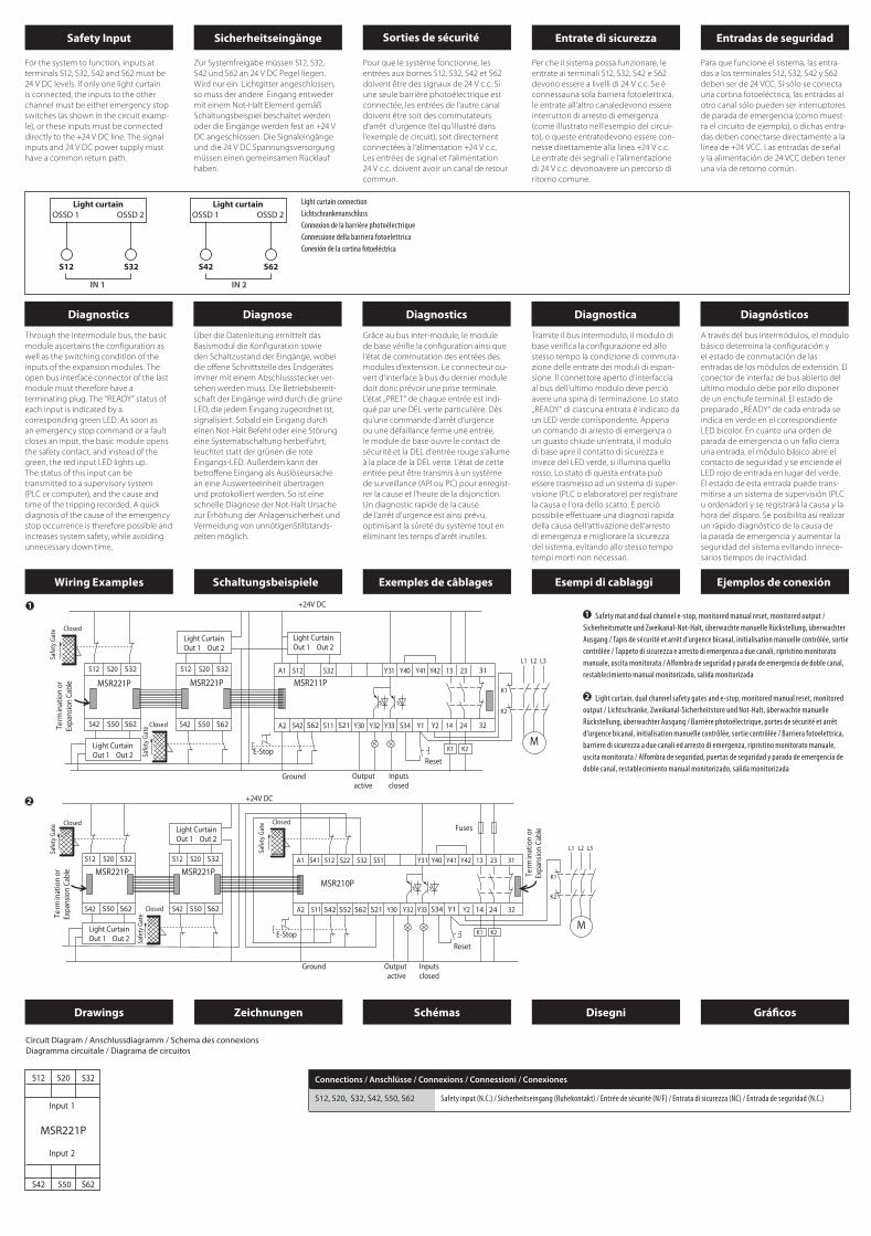
Mount in enclosure to a min. of IP54.
Einbau in Gehäuse nach min. IP54.
Monter dans un coff ret conforme au minimum à la norme IP54.
Montare in cabina con una protezione minima pari a IP54.
Montar en envolvente a un mínimo de IP54.
Removable terminals (‘P’ versions only) To remove, insert screwdriver and slowly move as shown.
Abnehmbare Klemmen (nur bei ‘P’- Ausführungen) Zum Abnehmen der Klemmen, Schraubendreher langsam wie dargestellt einsetzen.
Bornes amovibles (disponibles sur versions P uniquement) Pour démonter, insérer le tournevis et lui donner un léger mouvement comme il est indiqué.
Terminali amovibili (soltanto versioni ‘P’) Per la rimozione, inserire il cacciavite e muovere lentamente come indicato.
Terminales extraíbles (sólo versiones ‘P’) Para retirar, coloque un destornillador y muévalo lentamente como se indica.
mm (in)LED Indication / LED Anzeigen / Voyants / Indicazioni ai LED / Indicadores LED
Input 1
Input 2
OSSD1 output of light curtain to S12 terminal. OSSD2 output of light curtain to S32 terminal. S20 terminal: unconnected. / OSSD1 Ausgang der Lichtschranke an S12
Klemme. OSSD2 Ausgang der Lichtschranke an S32 Klemme. S20 Klemme: nicht angeschlossen. / Sortie OSSD1 de barrière photoélectrique à borne S12 Sortie OSSD2 de
barrière photoélectrique à borne S32 Borne S20 : non connectée / Uscita OSSD1 della barriera fotoelettrica al terminale S12. Uscita OSSD2 della barriera fotoelettrica al
terminale S32. Terminale S20: non connesso. / Salida OSSD1 de la cortina fotoeléctrica al terminal S12. Salida OSSD2 de la cortina fotoeléctrica al terminal S32. Terminal
S20: no conectado
OSSD1 output of light curtain to S42 terminal. OSSD2 output of light curtain to S62 terminal. S50 terminal: unconnected. / OSSD1 Ausgang der Lichtschranke an S42
Klemme. OSSD2 Ausgang der Lichtschranke an S62 Klemme. S50 Klemme: nicht angeschlossen. / Sortie OSSD1 de barrière photoélectrique à borne S42 Sortie OSSD2 de
barrière photoélectrique à borne S62 Borne S50 : non connectée / Uscita OSSD1 della barriera fotoelettrica al terminale S42. Uscita OSSD2 della barriera fotoelettrica al
terminale S62. Terminale S50: non connesso. / Salida OSSD1 de la cortina fotoeléctrica al terminal S42. Salida OSSD2 de la cortina fotoeléctrica al terminal S62. Terminal
S50: no conectado
Inputs / Eingänge / Entrées / Entrata / Entradas
CH1 input green illuminates when input closed / CH1 Eingang grün leuchtet auf, wenn Eingang
geschlossen ist / L‘entrée CH1 s‘allume en vert, lorsque le contact d‘entrée est fermé / L‘entrata CH1
si allumina di verde quando l‘entrata è chiusa / La luz verda de entrada CH1 se enciende cuando se
cierra la entrada
CH1 input red illuminates when input is open / CH1 Eingang rot leuchtet auf, wenn Eingang geöff net
ist / L‘entrée CH1 s‘allume en rouge, lorsque le contact d‘entrée est ouvert / L‘entrata CH1 si allumina di
rosso quando l‘entrata è aperta / La luz roja de entrada CH1 se enciende cuando se abre la entrada
CH2 input green illuminates when input closed / CH2 Eingang grün leuchtet auf, wenn Eingang
geschlossen ist / L‘entrée CH2 s‘allume en vert, lorsque le contact d‘entrée est fermé / L‘entrata CH2
si allumina di verde quando l‘entrata è chiusa / La luz verda de entrada CH2 se enciende cuando se
cierra la entrada
CH2 input red illuminates when input is open / CH2 Eingang rot leuchtet auf, wenn Eingang geöff net
ist / L‘entrée CH2 s‘allume en rouge, lorsque le contact d‘entrée est ouvert / L‘entrata CH2 si allumina di
rosso quando l‘entrata è aperta / La luz roja de entrada CH2 se enciende cuando se abre la entrada
Note / Hinweis / Remarque / NB / Nota
Inputs for both channels must be 24V DC. / Eingänge für beide Kanäle müssen 24V DC sein. / Les entrées des deux canaux doivent être alimentées en 24 V c.c. / Le entrate per entrambi i canali devono essere a 24V c.c. / Las entradas de ambos canales deben ser de 24V CC.
For the system to function, inputs at terminals S12,S32, S42 and S62 must be 24V DC levels. If only onelight curtain is connected, the inputs to the other channelmust be either emenrgency
stop switches (as shown in thecircuit example), or these inputs must be connected directly to the +24V DC line.The signal inputs and 24V DC power supply must have acommon return
path. / Das System kann nur funktionieren, wenn die Eingänge an den Klemmen S12, S32, S42 und S62 auf 24V DC Pegel liegen. Wenn nur eine Lichtschranke angeschlossen ist, müssen
die Eingänge an den anderen Kanal entweder Notaus-Schalter sein (wie auf dem Schaltkreisbeispiel gezeigt) oder diese Eingänge müssen direkt an die +24 VDC Leitung angeschlossen
sein. Die Signaleingänge und die 24 VDC Spannungsversorgung müssen einen gemeinsamen Rücklauf haben. / Pour que le système fonctionne, les entrées aux bornes S12, S32, S42 et S62
doivent être des signaux de 24 V c.c. Si une seule barrière photoélectrique est connectée, les entrées de l‘autre canal doivent être soit des commutateurs d‘arrêt d‘urgence (tel qu‘illustré dans
l‘exemple de circuit), soit directement connectées à l‘alimentation +24 V c.c.Les entrées de signal et l‘alimentation 24 V c.c. doivent avoir un canal de retour commun. / Per che il sistema
possa funzionare, le entrate ai terminali S12,S32, S42, e S62 devono essere a livelli di 24 V c.c. Se è connessa una sola barriera fotoelettrica, le entrate all‘altro canaledevono essere interruttori
di arresto di emergenza (come illustrato nell‘esempio del circuito), o queste entratedevono essere connesse direttamente alla linea +24 V c.c.Le entrate dei segnali e l‘alimentazione di 24 V
c.c. devonoavere un percorso di ritorno comune. / Para que funcione el sistema, las entradas a los terminales S12, S32, S42 y S62 deben ser de 24V CC. Si se conecta únicamente una cortina
fotoeléctrica, las entradas al otro canal sólo pueden ser interruptores de parada de emergencia (como muestra el circuito de ejemplo), o dichas entradas deben conectarse directamente a la
línea de +24V CC.Las entradas de señal y la alimentación de 24V CC deben tener una vía de retorno común.
1 Operation time (day, hour), Betriebszeit (Tag, Stunde) / Durée de service en (jours, heures) / Giorno/ora di durata dell’operazione / Tiempo operativo (día, hora)2 Cycle time (hour, sec), Anforderungsrate (Stunde, Sek) / Temps de cycle (heure, sec) / Ora/sec di tempo di ciclo / Tiempo de ciclo (hora, seg)
Safety Specifi cationSicherheitsbezogeneSpezifi kation
Spécifi cations liées à la sécurité
Specifi ca relativa alla sicurezza
Especifi caciones de seguridad
Wiring Examples Schaltungsbeispiele Exemples de câblages Esempi di cablaggi Ejemplos de conexión
Safety mat and dual channel e-stop, monitored manual reset, monitored output /
Sicherheitsmatte und Zweikanal-Not-Halt, überwachte manuelle Rückstellung, überwachter
Ausgang / Tapis de sécurité et arrêt d‘urgence bicanal, initialisation manuelle contrôlée, sortie
contrôlée / Tappeto di sicurezza e arresto di emergenza a due canali, ripristino monitorato
manuale, uscita monitorata / Alfombra de seguridad y parada de emergencia de doble canal,
restablecimiento manual monitorizado, salida monitorizada
Light curtain, dual channel safety gates and e-stop, monitored manual reset, monitored
output / Lichtschranke, Zweikanal-Sicherheitstore und Not-Halt, überwachte manuelle
Rückstellung, überwachter Ausgang / Barrière photoélectrique, portes de sécurité et arrêt
d‘urgence bicanal, initialisation manuelle contrôlée, sortie contrôlée / Barriera fotoelettrica,
barriere di sicurezza a due canali ed arresto di emergenza, ripristino monitorato manuale,
uscita monitorata / Alfombra de seguridad, puertas de seguridad y parada de emergencia de
doble canal, restablecimiento manual monitorizado, salida monitorizada
EN ISO 13849-1 IEC 61508/IEC 62061
PL e SIL 3
MTTFd [a] 1232 PFH [1/h] 9,19E-11
Cat. 4 HFT 1
DC avg. 99 % DC 99 %
TM (PTI) [a] 20
dop [d] / hop [h]1 365 / 24
tcycle [h]/[s]2 8 / 28,800
Safety Input Sicherheitseingänge Sorties de sécurité Entrate di sicurezza Entradas de seguridad
Light curtain connection
Lichtschrankenanschluss
Connexion de la barrière photoélectrique
Connessione della barriera fotoelettrica
Conexión de la cortina fotoeléctrica
Diagnostics Diagnose Diagnostics Diagnostica Diagnósticos
Dimensions / Abmessungen / Dimensions / Dimensioni / Dimensiones
Through the intermodule bus, the basic
module ascertains the confi guration as
well as the switching condition of the
inputs of the expansion modules. The
open bus interface connector of the last
module must therefore have a
terminating plug. The “READY” status of
each input is indicated by a
corresponding green LED. As soon as
an emergency stop command or a fault
closes an input, the basic module opens
the safety contact, and instead of the
green, the red input LED lights up.
The status of this input can be
transmitted to a supervisory system
(PLC or computer), and the cause and
time of the tripping recorded. A quick
diagnosis of the cause of the emergency
stop occurrence is therefore possible and
increases system safety, while avoiding
unnecessary down time.
Über die Datenleitung ermittelt das
Basismodul die Konfi guration sowie
den Schaltzustand der Eingänge, wobei
die off ene Schnittstelle des Endgerätes
immer mit einem Abschlussstecker ver-
sehen werden muss. Die Betriebsbereit-
schaft der Eingänge wird durch die grüne
LED, die jedem Eingang zugeordnet ist,
signalisiert. Sobald ein Eingang durch
einen Not-Halt Befehl oder eine Störung
eine Systemabschaltung herbeiführt,
leuchtet statt der grünen die rote
Eingangs-LED. Außerdem kann der
betroff ene Eingang als Auslöseursache
an eine Auswerteeinheit übertragen
und protokolliert werden. So ist eine
schnelle Diagnose der Not-Halt Ursache
zur Erhöhung der Anlagensicherheit und
Vermeidung von unnötigenStillstands-
zeiten möglich.
Grâce au bus inter-module, le module
de base vérifi e la confi guration ainsi que
l‘état de commutation des entrées des
modules d‘extension. Le connecteur ou-
vert d‘interface à bus du dernier module
doit donc prévoir une prise terminale.
L‘état „PRET“ de chaque entrée est indi-
qué par une DEL verte particulière. Dès
qu‘une commande d‘arrêt d‘urgence
ou une défaillance ferme une entrée,
le module de base ouvre le contact de
sécurité et la DEL d‘entrée rouge s‘allume
à la place de la DEL verte. L‘état de cette
entrée peut être transmis à un système
de surveillance (API ou PC) pour enregist-
rer la cause et l‘heure de la disjonction.
Un diagnostic rapide de la cause
de l‘arrêt d‘urgence est ainsi prévu,
optimisant la sûreté du système tout en
éliminant les temps d‘arrêt inutiles.
Tramite il bus intermodulo, il modulo di
base verifi ca la confi gurazione ed allo
stesso tempo la condizione di commuta-
zione delle entrate dei moduli di espan-
sione. Il connettore aperto d‘interfaccia
al bus dell‘ultimo modulo deve perciò
avere una spina di terminazione. Lo stato
„READY“ di ciascuna entrata è indicato da
un LED verde corrispondente. Appena
un comando di arresto di emergenza o
un guasto chiude un‘entrata, il modulo
di base apre il contatto di sicurezza e
invece del LED verde, si illumina quello
rosso. Lo stato di questa entrata può
essere trasmesso ad un sistema di super-
visione (PLC o elaboratore) per registrare
la causa e l‘ora dello scatto. È perciò
possibile eff ettuare una diagnosi rapida
della causa dell‘attivazione dell‘arresto
di emergenza e migliorare la sicurezza
del sistema, evitando allo stesso tempo
tempi morti non necessari.
A través del bus intermódulos, el modulo
básico determina la confi guración y
el estado de conmutación de las
entradas de los módulos de extensión. El
conector de interfaz de bus abierto del
ultimo modulo debe por ello disponer
de un enchufe terminal. El estado de
preparado „READY“ de cada entrada se
indica en verde en el correspondiente
LED bicolor. En cuanto una orden de
parada de emergencia o un fallo cierra
una entrada, el módulo básico abre el
contacto de seguridad y se enciende el
LED rojo de entrada en lugar del verde.
El estado de esta entrada puede trans-
mitirse a un sistema de supervisión (PLC
u ordenador) y se registrará la causa y la
hora del disparo. Se posibilita así realizar
un rápido diagnóstico de la causa de
la parada de emergencia y aumentar la
seguridad del sistema evitando innece-
sarios tiempos de inactividad.
For the system to function, inputs at
terminals S12, S32, S42 and S62 must be
24 V DC levels. If only one light curtain
is connected, the inputs to the other
channel must be either emergency stop
switches (as shown in the circuit examp-
le), or these inputs must be connected
directly to the +24 V DC line. The signal
inputs and 24 V DC power supply must
have a common return path.
Zur Systemfreigabe müssen S12, S32,
S42 und S62 an 24 V DC Pegel liegen.
Wird nur ein Lichtgitter angeschlossen,
so muss der andere Eingang entweder
mit einem Not-Halt Element gemäß
Schaltungsbeispiel beschaltet werden
oder die Eingänge werden fest an +24 V
DC angeschlossen. Die Signaleingänge
und die 24 V DC Spannungsversorgung
müssen einen gemeinsamen Rücklauf
haben.
Pour que le système fonctionne, les
entrées aux bornes S12, S32, S42 et S62
doivent être des signaux de 24 V c.c. Si
une seule barrière photoélectrique est
connectée, les entrées de l‘autre canal
doivent être soit des commutateurs
d‘arrêt d‘urgence (tel qu‘illustré dans
l‘exemple de circuit), soit directement
connectées à l‘alimentation +24 V c.c.
Les entrées de signal et l‘alimentation
24 V c.c. doivent avoir un canal de retour
commun.
Per che il sistema possa funzionare, le
entrate ai terminali S12, S32, S42 e S62
devono essere a livelli di 24 V c.c. Se è
connessauna sola barriera fotoelettrica,
le entrate all‘altro canaledevono essere
interruttori di arresto di emergenza
(come illustrato nell‘esempio del circui-
to), o queste entratedevono essere con-
nesse direttamente alla linea +24 V c.c.
Le entrate dei segnali e l‘alimentazione
di 24 V c.c. devonoavere un percorso di
ritorno comune.
Para que funcione el sistema, las entra-
das a los terminales S12, S32, S42 y S62
deben ser de 24 VCC. Si sólo se conecta
una cortina fotoeléctrica, las entradas al
otro canal sólo pueden ser interruptores
de parada de emergencia (como muest-
ra el circuito de ejemplo), o dichas entra-
das deben conectarse directamente a la
línea de +24 VCC. Las entradas de señal
y la alimentación de 24 VCC deben tener
una vía de retorno común.
The safety relay MSR221P can be used
in safety circuits according to DIN EN
60204-1/VDE 0113 part 1. Based on the
operation mode and wiring the below
mentioned safey requirements are
achievebale in maximum.
Specifi cations are applicable only if the
safety function is demanded at least
once within 6 months. All diagnostic
test are carried out at least before next
demand. The mission time (TM) for the
proof test interval (PTI) is adopted.
Components failure rates according to
SN29500.
Das Sicherheits-Relais MSR221P kann
in Sicherheitsstromkreisen nach DIN
EN 60204-1/VDE 0113 Teil 1 eingesetzt
werden. Je nach äußerer Beschaltung sind
max. die unten aufgeführten Anforderun-
gen zu erreichen.
Die Anforderungen der aufgeführten
Normen werden erfüllt, wenn die
Sicherheitsfunktion mindestens einmal
innerhalb von 6 Monaten betätigt wird.
Alle Diagnosetests werden spätestens bis
zur nächsten Anforderung ausgeführt.
Als Intervall für Wiederholungsprüfungen
(PTI) wird die Nutzungsdauer (TM) ange-
nommen, Fehlerraten der Komponenten
gemäß SN29500.
Le relais de sécurité MSR221P peut être
utilisé sur des circuits de sécurité con-
formément à la norme DIN EN 60204-1/
VDE 0113 partie 1. En fonction du mode
d‘exploitation et du câblage, les spécifi -
cations en matière de sécurité ci-dessous
peuvent êter suivies dans leur intégralité.
Les spécifi cations ne s‘appliquent que si
les actions de sécurité sont demandées au
moins fois tous les 6 mois. Tous les essais
de diagnostic sont entrepris au moins
avant la requête suivante. La période de
mission (PM), en ce qui concerne l‘interval
des essais (IE), est adoptée.
Les pannes des composants sont classées
en conformité avec la norme SN29500.
Il relè di sicurezza MSR221P può essere
usato in circuiti di sicurezza secondo DIN
EN 60204-1/VDE 0113 parte 1. Sulla base
del modo di funzionamento e il cablaggio
i requisiti di sicurezza sotto indicati sono
realizzabili in condizioni di massimo.
Le specifi che sono valide soltanto se la
funzione di sicurezza viene richiesta al-
meno una volta ogni 6 mesi. Tutti i test di
diagnostica sono eseguiti almeno prima
della richiesta successiva. È adottato il
tempo di missione (TM) per l‘intervallo del
test di prova (PTI).
Frequenza guasti componenti secondo
SN29500.
El relé de seguridad MSR221P puede
usarse en circuitos de seguridad según la
norma DIN EN 60204-1/VDE 0113 parte 1.
En función del modo de funcionamiento
y cableado, los requisitos de seguridad
que se citan más abajo son factibles en
grado máximo.
Las especifi caciones son aplicables
únicamente si se precisa la función de
seguridad al menos una vez cada 6
meses. Todas las pruebas diagnósticas se
realizarán como muy tarde antes de la si-
guiente petición. Se adopta el tiempo de
misión (TM) del intervalo de prueba (PTI).
Índices de fallo de los componentes
según SN29500.
Drawings
Drawings
Zeichnungen
Zeichnungen
Schémas
Schémas
Disegni
Disegni
Gráfi cos
Gráfi cos
Circuit Diagram / Anschlussdiagramm / Schema des connexions Diagramma circuitale / Diagrama de circuitos
Connections / Anschlüsse / Connexions / Connessioni / Conexiones
S12, S20, S32, S42, S50, S62 Safety input (N.C.) / Sicherheitseingang (Ruhekontakt) / Entrée de sécurité (N/F) / Entrata di sicurezza (NC) / Entrada de seguridad (N.C.)
Technical Support / Technische Unterstützung / Assistance technique / Assistenza tecnica / Asistencia técnica
ENGLISH
DEUTSCH
FRANÇAIS
ITALIANO
ESPAÑOL
PORTUGUÊS
POLSKI
ČESKY
SVENSKA
NEDERLANDS
БЪЛГАРСКИ
EESTI
SUOMI
ΕΛΛΗΝΙΚΆ
MAGYAR
ÍSLENSKA
LATVIEŠU VALODA
LIETUVIRŠKAI
MALTI
NORSK
ROMÂNĂ
SLOVENSKY
SLOVENŠČINA
TÜRKÇE
Installation of this product must not take place until the installer has obtained a copy of the manufacturer’s instructions in a language which he can understand. This instruction sheet is available in multiple languages at http://rockwellautomation.com/literature.
Dieses Produkt darf erst installiert werden, wenn der Installateur eine Kopie der Instruktionen des Herstellers in der Sprache eingeholt hat, die er versteht. Diese Instruktionen sind mehrsprachig erhältlich unter: http://rockwellautomation.com/literature.
Ce produit ne peut être installé avant l’obtention d’un duplicata des instructions du fabricant dans une langue compréhensible. La fi che d’instructions est disponible en plusieurs langues depuis le lien http://rockwellautomation.com/literature.
Non si deve procedere all’installazione di questo prodotto fin quando l’installatore non abbia ottenuto una copia delle istruzioni del produttore in una lingua che l’installatore possa capire. La presente scheda di istruzioni è disponibile in linguaggi multipli sul sito web http://rockwellautomation.com/literature.
Absténgase de instalar este producto a menos que el instalador disponga de un ejemplar de las instrucciones del fabricante en un idioma que pueda comprender. En http://rockwellautomation.com/literature puede encontrar esta hoja de instrucciones en varios idiomas.
A instalação deste produto não pode ser efectuada até que o montador tenha obtido uma cópia das instruções do fabricante numa língua que ele compreenda. Essa folha de instruções está disponível em diversas línguas em http://rockwellautomation.com/literature.
Nie należy przeprowadzać instalacji tego produktu aż do otrzymania przez montera instrukcji producenta w języku, który on rozumie. Te karty z instrukcjami są dostępne w wielu językach na: http://rockwellautomation.com/literature.
Instalace tohoto výrobku nesmí proběhnout, dokud instalující osoba neobdrží pokyny výrobce v jazyce, kterému rozumí. Tyto pokyny jsou k dispozici v několika jazycích na http://rockwellautomation.com/literature.
Denna produkt får inte installeras förrän installatören har skaff at ett exemplar av tillverkarens instruktioner på ett språk som han/hon förstår. Detta instruktionsblad fi nns på fl era språk på http://rockwellautomation.com/literature.
Het product mag pas worden geïnstalleerd wanneer de monteur beschikt over een exemplaar van de instructies van de fabrikant in een voor hem begrijpelijke taal. Dit instructieblad is in diverse talen verkrijgbaar op http://rockwellautomation.com/literature.
: http://rockwellautomation.com/literature
: http://rockwellautomation.com/literature
http://rockwellautomation.com/literature
Това устройство не трябва да се монтира, докато монтажника не разполага с инструкциите на производителя, на разбираем за него език. Инструкциите за монтаж ще намерите на различни езици в http://rockwellautomation.com/literature.
Selle toote installatsioon ei tohi toimuda enne kui installeerija on omandanud koopia tootja instruktsioonidega keeles mida ta ise valdab. Instruktsioonid erinvates keeltes on saadaval siin: http://rockwellautomation.com/literature.
Tämä tuote voidaan asentaa vasta kun asentaja on hankkinut valmistajan ohjeet kielellä, jota hän ymmärtää. Erikieliset ohjeet ovat ladattavissa sivustolta http://rockwellautomation.com/literature.
Εγκατάσταση του προϊόντος αυτού δεν πρέπει να γίνει πριν ο εγκαταστάτης προμηθευθεί αντίτυπο οδηγιών του κατασκευαστή σε γλώσσα που ο ίδιος καταλαβαίνει. Το εγχειρίδιο αυτό διατίθεται σε διόφορες γλώσσες στη διεύθυνση http://rockwellautomation.com/literature.
Ez a termék csak akkor helyezhető üzembe, ha az üzembehelyezést végző személy rendelkezésére áll a gyártó használati utasítása az általa ismert nyelven. Az utasítás több nyelven megtalálható itt: http://rockwellautomation.com/literature
Uppsetning á þessari vöru má ekki eiga sér stað fyrr en sá sem annast uppsetninguna hefur fengið afrit af leiðbeiningum framleiðanda á því tungumáli sem hann þekkir. Leiðbeiningarpésinn er tiltækur á mörgum tungumálum og er hægt að ná í hann hér: http://rockwellautomation.com/literature
Šī ražojuma uzstādīšanu nedrīkst veikt, pirms uzstādītājs nav saņēmis ražotāja instrukcijas tādā valodā ko viņš saprot. Šo instrukciju lapiņu var saņemt daudzās valodās no vietnes http://rockwellautomation.com/literature
Šito produkto įrengimas negali būti vykdomas tol, kol įrengėjas neturės gamintojo instrukcijų kopijos ta kalba, kurią jis supranta. Instrukciją galima rasti įvairiomis kalbomis tinklapyje http://rockwellautomation.com/literature
L-installazzjoni ta’ dan il-prodott mgħandux isir qabel ma l-installatur jakwista kopja tal-istruzzjonijiet tal-manifattur f ’lingwa li tista’ tiftiehem. Il-karta tal-istruzzjonijiet hija disponibbli f ’ħafna lingwi f ’http://rockwellautomation.com/literature.
Dette produktet må ikke installeres før installatøren har bruksanvisningen på et behersket språk. Dette instruksjonsarket kan fås i fl ere språk på http://rockwellautomation.com/literature.
Produsul nu trebuie să fi e instalat până când cel care instalează produsul nu a obţinut o copie a manualului de utilizare , în limba pe care o poate înţelege. Aceste instrucţiuni sunt valabile în mai multe limbi la adresa http://rockwellautomation.com/literature.
Inštalácia tohto výrobku nesmie prebehnúť, dokiaľ inštalujúca osoba nedostane pokyny výrobca v jazyku ktorému rozumie. Tieto pokyny sú k dispozícii v niekoľkých jazykoch na http://rockwellautomation.com/literature.
Tega izdelka se ne sme nameščati, če si oseba, ki ga namešča, ni priskrbela izvoda proizvajalčevih navodil v jeziku, ki ga razume. Ta list z navodili v številnih jezikih je na razpolago na http://rockwellautomation.com/literature.
Bu ürünün kurulmasının, ürünü kuracak kişinin üreticinin hazırladığı talimatların bir kopyasını, ki bu talimatlar bu kişinin anlayacağı bir dilde olacaktır, elde edene kadar gerçekleşmemesi gerekir. Bu talimatlar pek çok dilde şu web-sayfasında mevcuttur: http://rockwellautomation.com/literature
Installation Installation Installation Installazione Instalación
Mount in enclosure to a min. of IP54.
Einbau in Gehäuse nach min. IP54.
Monter dans un coff ret conforme au minimum à la norme IP54.
Montare in cabina con una protezione minima pari a IP54.
Montar en envolvente a un mínimo de IP54.
Removable terminals (‘P’ versions only) To remove, insert screwdriver and slowly move as shown.
Abnehmbare Klemmen (nur bei ‘P’- Ausführungen) Zum Abnehmen der Klemmen, Schraubendreher langsam wie dargestellt einsetzen.
Bornes amovibles (disponibles sur versions P uniquement) Pour démonter, insérer le tournevis et lui donner un léger mouvement comme il est indiqué.
Terminali amovibili (soltanto versioni ‘P’) Per la rimozione, inserire il cacciavite e muovere lentamente come indicato.
Terminales extraíbles (sólo versiones ‘P’) Para retirar, coloque un destornillador y muévalo lentamente como se indica.
mm (in)LED Indication / LED Anzeigen / Voyants / Indicazioni ai LED / Indicadores LED
Input 1
Input 2
OSSD1 output of light curtain to S12 terminal. OSSD2 output of light curtain to S32 terminal. S20 terminal: unconnected. / OSSD1 Ausgang der Lichtschranke an S12
Klemme. OSSD2 Ausgang der Lichtschranke an S32 Klemme. S20 Klemme: nicht angeschlossen. / Sortie OSSD1 de barrière photoélectrique à borne S12 Sortie OSSD2 de
barrière photoélectrique à borne S32 Borne S20 : non connectée / Uscita OSSD1 della barriera fotoelettrica al terminale S12. Uscita OSSD2 della barriera fotoelettrica al
terminale S32. Terminale S20: non connesso. / Salida OSSD1 de la cortina fotoeléctrica al terminal S12. Salida OSSD2 de la cortina fotoeléctrica al terminal S32. Terminal
S20: no conectado
OSSD1 output of light curtain to S42 terminal. OSSD2 output of light curtain to S62 terminal. S50 terminal: unconnected. / OSSD1 Ausgang der Lichtschranke an S42
Klemme. OSSD2 Ausgang der Lichtschranke an S62 Klemme. S50 Klemme: nicht angeschlossen. / Sortie OSSD1 de barrière photoélectrique à borne S42 Sortie OSSD2 de
barrière photoélectrique à borne S62 Borne S50 : non connectée / Uscita OSSD1 della barriera fotoelettrica al terminale S42. Uscita OSSD2 della barriera fotoelettrica al
terminale S62. Terminale S50: non connesso. / Salida OSSD1 de la cortina fotoeléctrica al terminal S42. Salida OSSD2 de la cortina fotoeléctrica al terminal S62. Terminal
S50: no conectado
Inputs / Eingänge / Entrées / Entrata / Entradas
CH1 input green illuminates when input closed / CH1 Eingang grün leuchtet auf, wenn Eingang
geschlossen ist / L‘entrée CH1 s‘allume en vert, lorsque le contact d‘entrée est fermé / L‘entrata CH1
si allumina di verde quando l‘entrata è chiusa / La luz verda de entrada CH1 se enciende cuando se
cierra la entrada
CH1 input red illuminates when input is open / CH1 Eingang rot leuchtet auf, wenn Eingang geöff net
ist / L‘entrée CH1 s‘allume en rouge, lorsque le contact d‘entrée est ouvert / L‘entrata CH1 si allumina di
rosso quando l‘entrata è aperta / La luz roja de entrada CH1 se enciende cuando se abre la entrada
CH2 input green illuminates when input closed / CH2 Eingang grün leuchtet auf, wenn Eingang
geschlossen ist / L‘entrée CH2 s‘allume en vert, lorsque le contact d‘entrée est fermé / L‘entrata CH2
si allumina di verde quando l‘entrata è chiusa / La luz verda de entrada CH2 se enciende cuando se
cierra la entrada
CH2 input red illuminates when input is open / CH2 Eingang rot leuchtet auf, wenn Eingang geöff net
ist / L‘entrée CH2 s‘allume en rouge, lorsque le contact d‘entrée est ouvert / L‘entrata CH2 si allumina di
rosso quando l‘entrata è aperta / La luz roja de entrada CH2 se enciende cuando se abre la entrada
Note / Hinweis / Remarque / NB / Nota
Inputs for both channels must be 24V DC. / Eingänge für beide Kanäle müssen 24V DC sein. / Les entrées des deux canaux doivent être alimentées en 24 V c.c. / Le entrate per entrambi i canali devono essere a 24V c.c. / Las entradas de ambos canales deben ser de 24V CC.
For the system to function, inputs at terminals S12,S32, S42 and S62 must be 24V DC levels. If only onelight curtain is connected, the inputs to the other channelmust be either emenrgency
stop switches (as shown in thecircuit example), or these inputs must be connected directly to the +24V DC line.The signal inputs and 24V DC power supply must have acommon return
path. / Das System kann nur funktionieren, wenn die Eingänge an den Klemmen S12, S32, S42 und S62 auf 24V DC Pegel liegen. Wenn nur eine Lichtschranke angeschlossen ist, müssen
die Eingänge an den anderen Kanal entweder Notaus-Schalter sein (wie auf dem Schaltkreisbeispiel gezeigt) oder diese Eingänge müssen direkt an die +24 VDC Leitung angeschlossen
sein. Die Signaleingänge und die 24 VDC Spannungsversorgung müssen einen gemeinsamen Rücklauf haben. / Pour que le système fonctionne, les entrées aux bornes S12, S32, S42 et S62
doivent être des signaux de 24 V c.c. Si une seule barrière photoélectrique est connectée, les entrées de l‘autre canal doivent être soit des commutateurs d‘arrêt d‘urgence (tel qu‘illustré dans
l‘exemple de circuit), soit directement connectées à l‘alimentation +24 V c.c.Les entrées de signal et l‘alimentation 24 V c.c. doivent avoir un canal de retour commun. / Per che il sistema
possa funzionare, le entrate ai terminali S12,S32, S42, e S62 devono essere a livelli di 24 V c.c. Se è connessa una sola barriera fotoelettrica, le entrate all‘altro canaledevono essere interruttori
di arresto di emergenza (come illustrato nell‘esempio del circuito), o queste entratedevono essere connesse direttamente alla linea +24 V c.c.Le entrate dei segnali e l‘alimentazione di 24 V
c.c. devonoavere un percorso di ritorno comune. / Para que funcione el sistema, las entradas a los terminales S12, S32, S42 y S62 deben ser de 24V CC. Si se conecta únicamente una cortina
fotoeléctrica, las entradas al otro canal sólo pueden ser interruptores de parada de emergencia (como muestra el circuito de ejemplo), o dichas entradas deben conectarse directamente a la
línea de +24V CC.Las entradas de señal y la alimentación de 24V CC deben tener una vía de retorno común.
1 Operation time (day, hour), Betriebszeit (Tag, Stunde) / Durée de service en (jours, heures) / Giorno/ora di durata dell’operazione / Tiempo operativo (día, hora)2 Cycle time (hour, sec), Anforderungsrate (Stunde, Sek) / Temps de cycle (heure, sec) / Ora/sec di tempo di ciclo / Tiempo de ciclo (hora, seg)
Safety Specifi cationSicherheitsbezogeneSpezifi kation
Spécifi cations liées à la sécurité
Specifi ca relativa alla sicurezza
Especifi caciones de seguridad
Wiring Examples Schaltungsbeispiele Exemples de câblages Esempi di cablaggi Ejemplos de conexión
Safety mat and dual channel e-stop, monitored manual reset, monitored output /
Sicherheitsmatte und Zweikanal-Not-Halt, überwachte manuelle Rückstellung, überwachter
Ausgang / Tapis de sécurité et arrêt d‘urgence bicanal, initialisation manuelle contrôlée, sortie
contrôlée / Tappeto di sicurezza e arresto di emergenza a due canali, ripristino monitorato
manuale, uscita monitorata / Alfombra de seguridad y parada de emergencia de doble canal,
restablecimiento manual monitorizado, salida monitorizada
Light curtain, dual channel safety gates and e-stop, monitored manual reset, monitored
output / Lichtschranke, Zweikanal-Sicherheitstore und Not-Halt, überwachte manuelle
Rückstellung, überwachter Ausgang / Barrière photoélectrique, portes de sécurité et arrêt
d‘urgence bicanal, initialisation manuelle contrôlée, sortie contrôlée / Barriera fotoelettrica,
barriere di sicurezza a due canali ed arresto di emergenza, ripristino monitorato manuale,
uscita monitorata / Alfombra de seguridad, puertas de seguridad y parada de emergencia de
doble canal, restablecimiento manual monitorizado, salida monitorizada
EN ISO 13849-1 IEC 61508/IEC 62061
PL e SIL 3
MTTFd [a] 1232 PFH [1/h] 9,19E-11
Cat. 4 HFT 1
DC avg. 99 % DC 99 %
TM (PTI) [a] 20
dop [d] / hop [h]1 365 / 24
tcycle [h]/[s]2 8 / 28,800
Safety Input Sicherheitseingänge Sorties de sécurité Entrate di sicurezza Entradas de seguridad
Light curtain connection
Lichtschrankenanschluss
Connexion de la barrière photoélectrique
Connessione della barriera fotoelettrica
Conexión de la cortina fotoeléctrica
Diagnostics Diagnose Diagnostics Diagnostica Diagnósticos

Technical Specifi cation Technische Spezifi kation Spécifi cations techniques Specifi che tecniche Especifi caciones técnicas
Power supply Spannungsversorgung Alimentation Alimentazione Alimentación
24 V DC from the base unit (PELV / SELV) 24 V DC vom Hauptgerät (PELV / SELV) 24 V c.c. d’un module de base (PELV / SELV) 24V CC desde la unidad base (PELV / SELV) 24V c.c. dall’unità di base (PELV / SELV)
Power consumption Leistungsverbrauch Consommation Consumo energetico Consumo eléctrico
2 W 2 W 2 W 2 W 2 W
Safety inputs Schutzeingänge Contacts d’entrée de sécurité Entrate di sicurezza Entradas de seguridad
1 N.C., 2 N.C. or 3 N.C. or mat 1 N.C., 2 N.C. oder 3 N.C. oder Sicherheitsmatte 1, 2 ou 3 N.F. ou tapis 1 N.C., 2 N.C. ó 3 N.C. o alfombra 1 N.C., 2 N.C. o 3 N.C. o pedana
Input simultaneity Eingangsgleichzeitigkeit Simultanéité des entrées Simultaneità d’entrata Simultaneidad de entrada
Infi nite Unbegrenzt Infi nie Infi nita Infi nita
Max. allowable input resistance Max. zulässiger Eingangswiderstand Résistance max. d’entrée Max resistenza d’entrata permissibile Resistencia máxima de entrada permitida
900 ohms 900 Ohm 900 ohms 900 ohms 900 ohmios
Indication LED’s Anzeige-LEDs DEL d’état LED di indicazione LEDs indicadores
Green = Input 1 closed
Red = Input 1 open
Green = Input 2 closed
Red = Input 2 open
Grün = Eingang 1 geschlossen
Rot = Eingang 1 geöff net
Grün = Eingang 2 geschlossen
Rot = Eingang 2 geöff net
Vert = Entrée 1 fermée
Rouge = Entrée 1 ouverte
Vert = Entrée 2 fermée
Rouge = Entrée 2 ouverte
Verde = Entrata 1 chiusa
Rosso = Entrata 1 aperta
Verde = Entrata 2 chiusa
Rosso = Entrata 2 aperta
Verde = Entrada 1 cerrada
Rojo = Entrada 1 abierta
Verde = Entrada 2 cerrada
Rojo = Entrada 2 abierta
Impulse withstand voltage Prüfspannung Tension impulsionnelle admise IMassima tensione d’impulso sosten. Voltaje impulsivo no disruptivo
2500 V 2500 V 2500 V 2500 V 2500 V
Pollution degree Verschmutzungsgrad Indice de pollution Grado di contaminazione Grado de contaminación
2 2 2 2 2
Installation group Installationsgruppe Groupe de montage Gruppo d’installazione Grupo de instalación
Overvoltage catagory III, VDE 0110-1 Überspannungskategorie III, VDE 0110-1 Catègorie de surtension,III, VDE 0110-1 Categoria di sovratensione III, VDE 0110-1 Categoría de sobrevoltaje III, VDE 0110-1
Operating temperature Betriebstemperatur Température de service Temperatura d’esercizio Temperatura operativa
-5 °C .... +55 °C (+23 °F .... 131 °F) -5 °C .... +55 °C (+23 °F .... 131 °F) -5 °C .... +55 °C (+23 °F .... 131 °F) -5 °C .... +55 °C (+23 °F .... 131 °F) -5 °C .... +55 °C (+23 °F .... 131 °F)
Humidity Feuchtigkeit Humidité Umidità Humedad
90% RH 90% RH 90% RH 90% RH 90% RH
Enclosure protection Gehäuseschutz Indice de protection enceinte Protezione chiusura Protección envolvente
IP40 (NEMA 1) IP40 (NEMA 1) IP40 (NEMA 1) IP40 (NEMA 1) IP40 (NEMA 1)
Terminal protection Klemmenschutz Protection aux bornes Protezione terminali Protección terminales
IP20 IP20 IP20 IP20 IP20
Conductor size Leiterquerschnitt Diamètre conducteur Dimensioni conduttori Diámetro del conductor
0.2 - 2.5 mm2 (24 -12 AWG) 0.2 - 2.5 mm2 (24 -12 AWG) 0.2 - 2.5 mm2 (24 -12 AWG) 0.2 - 2.5 mm2 (24 -12 AWG) 0.2 - 2.5 mm2 (24 -12 AWG)
Torque settings - terminal screws Drehmomentwerte - Klemmenschrauben Couple des vis de bornes Tarature di coppia - viti terminale Valores de par - tornillos de los terminales
0.6 Nm - 0.8 Nm (5 - 7 lb•in) 0.6 Nm - 0.8 Nm (5 - 7 lb•in) 0.6 Nm - 0.8 Nm (5 - 7 lb•in) 0.6 Nm - 0.8 Nm (5 - 7 lb•in) 0.6 Nm - 0.8 Nm (5 - 7 lb•in)
Case material Gehäusematerial Composition du boîtier Materiale cassa Material de la carcasa
Polyamide PA 6.6 Polyamid PA 6.6 Polyamide PA 6.6 Poliammide PA 6.6 Poliamida PA 6.6
Mounting Befestigung Montage Supporto Montaje
35 mm DIN rail in enclosure to a min of IP54 35 mm DIN-Schiene in Einbaugehäuse nach mind IP54 Rail DIN de 35 mm dans un boîtier IP54 minimum Rotaia DIN 35 mm in cabina con IP54 al minimo Riel DIN de 35 mm en envolvente a un mín. de IP54
Weight Gewicht Poids Peso Peso
95 g (0.21 lb) 95 g (0.21 lb) 95 g (0.21 lb) 95 g (0.21 lb) 95 g (0.21 lb)
Vibration Vibration Vibrations Vibrazioni Vibración
10-55 Hz, 0.35 mm 10-55 Hz, 0.35 mm 10-55 Hz, 0.35 mm 10-55 Hz, 0.35 mm 10-55 Hz, 0.35 mm
Minotaur MSR221PMonitoring Safety Relay - Installation Instructions
Sicherheitsrelais - Installationsanleitung
Relais de sécurité de surveillance - Notice d’installation
Relé di monitoraggio di sicurezza - Istruzioni per l’installazione
Relé de seguridad de monitorización - Instrucciones de instalación
10000176988 ver 00, Dwg. No: 95302175, EO: 0329, Issue 2, April 2011
This device is intended to be part of the safety
related control system of a machine.
SAFETY NOTESBefore installation, a risk assessment
should be performed to determine
whether the specifi cations of this device
are suitable for all foreseeable
operational and environmental
characteristics of the machine to which it
is to be fi tted. At regular intervals during
the life of the machine check whether
the characteristics foreseen remain valid.
Danger of serious injuries!
Misuse can result in malfunction.
The device may only be started up, assembled
or retrofi tted by an authorized and trained personnel.
Installation must be in accordance with the
following steps.
Danger of serious injuries!
Incorrect installation or manipulation can
result in serious injuries.
Do not defeat, tamper, remove or bypass
this unit.
Responsibility cannot be accepted for
a failure of this device if the procedures
given in this sheet are not implemented
or if it is used outside the recommended
specifi cations in this sheet.
NOTE: The safety inputs of these products are
described as normally closed (N.C.), ie. with the
guard closed, actuator in place (where relevant) and
the machine able to be started.
Exposure to shock and/or vibration in excess
of those stated in IEC 60068 part: 2-6/7 should
be prevented. Adherence to the recommended
inspection and maintenance instructions forms part
of the warranty.
NOTE: All information comply with state of this
publication. Subject to change without notice.
REPAIRIf there is any malfunction or damage, no
attempts or repair should be made. The
unit should be replaced before machine
operation is allowed.
DO NOT DISMANTLE THE UNIT.
Rockwell Automation hereby declares that
MSR221P is in conformity with Directive(s)
2004/108/EC, 2006/42/EC as specifi ed in the
Declaration of Conformity available from www.
rockwellautomation.com/ products/ certifi cation
All four inputs of the MSR221P must be at 24 V DC
levels to confi rm its operational status to the basic
module over the system bus. The safety contacts
can be closed (relay energised) only if all inputs of
the complete system are activated (green LED on).
If an emergency stop input device deactivates one
input, the safety contacts open (relay deenergised)
immediately. With positive input signals and dual
channel connection of emergency stop switching
devices, cross-fault monitoring is not done by the
MSR221P, since this function is usually integrated
into 2-channel light curtains and scanners with
semiconductor outputs. Since all inputs of the
system are interrogated continuously, unused inputs
of the MSR221P must be connected directly to the
+24 V DC supply circuit.
Dieses Gerät ist als Teil des sicherheitsrelevanten
Kontrollsystems einer Maschine vorgesehen.
ALLGEMEINE SICHERHEITSHINWEISEFür die Maschine, in die dieses Gerät
eingebaut wird, muss eine Risikobeurtei-
lung durchgeführt werden. Anhand der
Risikobeurteilung muss geprüft werden,
ob die Spezifi kationen dieses Gerätes
den Betriebs- und Umgebungsbedin-
gungen der Maschine entsprechen.
In regelmäßigen Abständen, während
der Lebensdauer der Maschine, ist zu
überprüfen, ob die vorhergesehenen
Spezifi kationen weiterhin gültig sind.
Gefahr von schweren Verletzungen!
Durch unsachgemäße Montage kann es zu
Fehlfunktionen kommen.
Die Montage darf nur durch fachlich qualifi zier-
tes Personal erfolgen.
Die nachfolgend beschriebenen Arbeitsschritte
müssen eingehalten werden.
Gefahr von schweren Verletzungen!
Durch unsachgemäßen Gebrauch kann es zu
schweren Verletzungen kommen.
Das Gerät niemals überbrücken.
Es kann keinerlei Verantwortung für ein
Versagen dieses Gerätes übernommen
werden, wenn die in diesem Schriftblatt
gegebenen Verfahrensweisen nicht imple-
mentiert wurden, oder wenn sie außerhalb
der auf diesem Schriftblatt empfohlenen
Spezifi kationen verwendet werden.
HINWEIS: Die Sicherheitskontakte der Schutzvor-
richtung sind als Ruhekontakte (N.C.) beschrieben,
d.h. bei geschlossener Schutzvorrichtung sind die
Betätigungselemente in Position (falls zutreff end)
und die Maschine ist startfähig.
Eine Aussetzung an Stoßbelastungen und/oder
Vibrationen, die über den in IEC 60068, Teil 2-6/7 an-
gegebenen Werten liegen, sollte verhindert werden.
Die Einhaltung der empfohlenen Inspektions- und
Wartungsvorschriften ist Teil der Garantie.
HINWEIS: Alle Angaben entsprechen dem
aktuellen Stand der Veröff entlichung. Änderungen
behalten wir uns jederzeit vor.
REPARATURBei Fehlfunktion oder Beschädigung
dürfen keine Reparaturversuche unter-
nommen werden. Das Gerät muss er-
setzt werden, bevor ein weiterer Betrieb
der Maschine zugelassen wird.
DAS GERÄT DARF NICHT AUSEINAN-DERGEBAUT WERDEN.
Hiermit erklärt Rockwell Automation, dass
MSR221P wie in der Konformitätserklärung
angegeben, den Richtlinien 2004/108/EG,
2006/42/EG genügt, erhältlich von www.
rockwellautomation.com/products/certifi cation
Liegen an allen vier Eingangskreisen des MSR221P
+24 V DC an, so wird die Freigabemeldung über das
Flachbandkabel zum Basismodul übertragen. Erst
wenn von allen Eingängen des Systems die Freigabe
vorliegt, können die Sicherheitskontakte geschlos-
sen werden. Wird ein Not-Halt Element betätigt, so
dass der entsprechende Eingang spannungslos wird,
öff net das Basismodul sofort die Sicherheitskon-
takte. Die Ansteuerung der MSR221P Eingänge mit
positiven Eingangssignalen bedingt, dass bei einer
zweikanaligen Beschaltung mit Not-Halt Tastern etc.
keine Querschlussüberwachung erfolgt. Zweikanali-
ge Sicherheitslichtgitter oder Scanner haben diese
Funktion jedoch üblicherweise integriert. Da ständig
alle vorhandenen Eingänge des Systems abgefragt
werden, müssen auch unbenutzte Eingänge beschal-
tet werden (+24 V auf freie Eingangsklemmen der
Lichtgittermodule legen).
Ce dispositif est étudié pour être incorporé dans le
système de contrôle pour la sécurité d’une machine.
CONSIGNES DE SÉCURITÉAvant l’installation, on doit eff ectuer une
évaluation des risques pour déterminer
si les spécifi cations de ce dispositif sont
appropriées pour toutes les caractéris-
tiques de service et du milieu d’utilisation
prévues pour la machine sur laquelle il
sera monté. Vérifi er, à des échéances ré-
gulières au cours de la vie de la machine,
que les caractéristiques prévues soient
toujours valables.
Danger de blessures graves !
Une mauvaise utilisation peut entraîner un
mauvais fonctionnement.
Seul du personnel formé et autorisé a le droit de
mettre en service, assembler ou monter l‘appareil.
L‘installation doit être eff ectuée.
Danger de blessures graves !
Une mauvaise installation ou une manipu-
lation incorrecte peut entraîner de graves
blessures.
Ne pas altérer la confi guration, modifi er, retirer
ou contourner cette unité.
Toute responsabilité est déclinée pour
les défaillances de cet appareil si les pro-
cédures décrites dans la présente notice
ne sont pas appliquées ou si l’appareil est
utilisé hors des spécifi cations recomman-
dées dans cette même notice.
REMARQUE : Les entreés de sécurité de ces
produits sont décrits comme normalement fermés
(N.F), c’est-à-dire lorsque la protection est fermée,
l’actionneur est en place (si applicable) et la machine
est en état de démarrer.
Eviter toute exposition à des chocs et/ou des
vibrations supérieurs à ceux qui sont spécifi és
dans la norme IEC 60068 part 2-6/7. Le respect des
instructions relatives à l’inspection, au contrôle et à
l’entretien de cet appareil rentre dans l’application
de la garantie.
REMARQUE : Toutes les indications fournies
correspondent aux connaissances actuelles au mo-
ment de la publication. Sous réserve de modifi cation
à tout moment.
RÉPARATIONEn cas de défaut de fonctionnement
ou d’endommagement, ne jamais
essayer de réparer le dispositif. Il doit être
remplacé avant de remettre la machine
en service.
NE JAMAIS DÉMONTER LE DISPOSITIF.
Rockwell Automation déclare par la
présente que le MSR221P est conforme aux
directives 2004/108/EC, 2006/42/EC telles
que spécifi ées dans la déclaration de conformité
consultable et disponible sur le lien www.
rockwellautomation.com/products/certifi cation
Les quatre entrées du MSR221P doivent être alimen-
tées en 24 V c.c. pour confi rmer son état de service au
module de base grâce au bus interne. Les contacts
de sécurité peuvent uniquement être fermés
(relais excités) si toutes les entrées du système sont
activées (DEL verte allumée). Si un dispositif d‘arrêt
d‘urgence désactive une entrée, les contacts de sé-
curité s‘ouvrent (relais désexcités) immédiatement.
Avec des signaux d‘entrée positifs et la connexion
bi-canal des dispositifs d‘arrêt d‘urgence, le contrôle
des défaillances entre circuit n‘est pas assuré par le
MSR221puisque cette fonction est généralement
intégrée aux barrières photoélectriques bicanal et
aux scanners à sorties à semi-conducteur. Puisque
toutes les sorties du système sont continuellement
interrogées, les entrées inutilisées du MSR221
doivent être directement connectées au circuit
d‘alimentation +24 V c.c.
Questo dispositivo fa parte del sistema di comando
relativo alla sicurezza di una macchina.
ISTRUZIONI DI SICUREZZAPrima dell’installazione occorre eseguire
una valutazione die rischi per stabilire se
le specifi che del dispositivo siano adatte
per tutte le caratteristiche operative ed
ambientali che si possano anticipare per
la macchina su cui deve essere montato.
Periodicamente durante la durata utile
della macchina occorre verifi care se le
caratteristiche previste rimangono valide.
Pericolo di lesioni gravi!
Un uso scorretto può causare un funzionamento
anomalo.
Il dispositivo può essere soltanto avviato, montato,
o aggiornato da personale autorizzato e addestrato.
L‘installazione deve essere conforme alle
seguenti fasi.
Pericolo di lesioni gravi!
Una installazione o un trattamento scorretti
possono causare lesioni gravi.
Non vanifi care, manomettere, rimuovere o
bypassare questa.
Si declina ogni responsabilità per il
mancato funzionamento del presente
dispositivo se le procedure indicate in
questa scheda non sono messe in atto o
se il dispositivo viene utilizzato in modo
che esula dalle specifi che consigliate in
questa scheda.
NB: Le entrate di sicurezza di questi prodotti sono de-
scritte come normalmente chiuse (NC), vale a dire con
la protezione chiusa, l’attuatore in posizione (ove sia
pertinente) e la macchina in grado di essere avviata.
Occorre evitare l’esposizione ad impatti e/o a vibrazioni
che eccedano quelli indicati nella specifi ca CEI 60068
parte: 2-6/7. L’osservanza delle istruzioni di ispezione
e di manutenzione consigliate formano parte della
garanzia.
NB: Tutte le indicazioni corrispondono allo stato
attuale della pubblicazione. Ci riserviamo il diritto di
apportare modifi che in qualsiasi momento.
RIPARAZIONEIn caso di funzionamento anomalo o di
danno, non si deve cercare di eff ettuare
una riparazione. L’unità deve essere
sostituita prima di ricominciare a far
funzionare la macchina. NON SMONTARE L’UNITÀ.
Con la presente Rockwell Automation
dichiara che MSR221P è conforme alle
Direttive 2004/108/EC, 2006/42/EC come
specifi cate nella Dichiarazione di conformità
disponibile da www.
rockwellautomation.com/products/certifi cation
Tutte le quattro entrate del MSR221P devono essere
alimentate a 24 V c.c. per confermare il suo stato
di servizio al modulo di base sul bus del sistema.
I contatti di sicurezza possono essere chiusi (relè
sotto tensione) soltanto se tutte le entrate del
sistema completo sono attivate (LED verde illumi-
nato). Se un dispositivo di arresto di emergenza
disattiva un‘entrata, i contatti di sicurezza si aprono
immediatamente (relè disattivato). Con segnali
positivi di entrata e la connessione a canale doppio
dei dispositivi d‘arresto di emergenza, il controllo
incrociato dei guasti non è eseguito dal MSR221P,
in quanto tale funzione è di solito integrata nelle
barriere fotoelettriche a due canali e negli scanner
con uscite a semiconduttore. Poiché tutte le entrate
del sistema sono interrogate in continuazione, le
entrate non utilizzate del MSR221P devono essere
connesse direttamente al circuito di alimentazione
di +24 V c.c.
Este dispositivo está concebido como parte
integrante del sistema de control de seguridad
correspondiente de una máquina.
INDICACIONES DE SEGURIDADAntes de proceder a la instalación,
deberán realizarse estudios de riesgos
que determinen la idoneidad de las
especifi caciones de este dispositivo
para todas las características operativas
y ambientales previsibles de la máquina
donde va a ser colocado. Revise regu-
larmente la máquina para cerciorarse de
que las características previsibles siguen
siendo válidas.
Peligro de lesiones graves!
Un uso incorrecto puede derivar en fallos de
funcionamiento.
El dispositivo sólo podrá arrancar, montarse o adap-
tarse por personal autorizado y debidamente capacitado.
La instalación deberá realizarse según los pasos
que fi guran a continuación.
Peligro de lesiones graves!
La incorrecta instalación o manipulación de
este producto puede producir lesiones graves.
No malogre, manipule, retire ni desvíe esta
unidad unità.
Se declina cualquier tipo de responsabi-
lidad por fallos en el funcionamiento de
este dispositivo resultantes del incumpli-
miento de las instrucciones expuestas en
esta hoja o del uso ajeno a las especifi ca-
ciones aquí recomendadas.
NOTA: Los contactos de entrada de estos productos
se describen como normalmente cerrados (o N.C.),
es decir, con el protector cerrado, el accionador en
su lugar (si procede) y la máquina en condiciones
de arrancar.
Deberá evitarse la exposición a golpes o vibraciones
superiores a los niveles indicados en la CEI 60068:
2-6/7. El cumplimiento de las instrucciones de
inspección y mantenimiento recomendadas forma
parte de la garantía.
NOTA: Todos los datos se corresponden con la fecha
de publicación. Nos reservamos el derecho a introducir
cambios sin previo aviso.
REPARACIÓNSi hubiera algún defecto o avería, no
intente repararlos. Sustituya la unidad
antes de autorizar el funcionamiento de
la máquina.
NO DESMONTE LA UNIDAD.
Rockwell Automation declara por la
presente que el MSR221P cumple las
Directivas 2004/108/EC, 2006/42/ EC según
se especifi ca en la Declaración de conformidad. Para
obtenerla, visite www.
rockwellautomation.com/products/certifi cation
Las cuatro entradas del MSR221P deben tener una
alimentación de 24 VDC para confi rmar su estado
operativo al modelo básico a través del bus de
sistema. Los contactos de seguridad pueden cerrarse
(relé activado) sólo si se activan todas las entradas
de todo el sistema (LED verde encendido). Si un
dispositivo de entrada de parada de emergencia
desactiva una entrada, los contactos de seguridad
se abrirán inmediatamente (relé desactivado). Con
señales de entrada positivas y conexión de canal
doble de dispositivos de conmutación de parada
de emergencia, el MSR221P no realiza la monitori-
zación de fallos cruzados ya que esta función suele
integrarse en cortinas fotoeléctricas y escáneres
de dos canales con salidas de semiconductor.
Como todas las entradas del sistema se interrogan
constantemente, las entradas no usadas del
MSR221P deben conectarse directamente al circuito
de alimentación de +24 VCC.
English (original)
Declaration of Conformity Konformitätserklärung Déclaration de Conformité Dichiarazione di conformità Declaración de conformidad
Deutsch (original) Français (traduction) Italiano (traduzione) Español (traducción)
WARNING WARNUNG AVERTISSEMENT AVVERTENZA! ADVERTENCIA!
AVERTISSEMENT AVVERTENZA! ADVERTENCIA!WARNUNGWARNING
10000176988 ver 00, Dwg. No: 95302175, Issue 2, April 2011 Copyright ©2011 Rockwell Automation, Inc. All Rights Reserved. Printed in Germany.
Functional Description Funktionsbeschreibung Description fonctionnelle Descrizione funzionale Descripción funcional