telecommunications and navigation strategies in · pdf filetelecommunications and navigation...
TRANSCRIPT
Telecommunications and Navigation Strategies in NASA�s Mars Exploration Program
Chad Edwards
DESCANSO SeminarMarch 15, 2001
010315 cde-2
Outline
• Introduction & Acknowledgments• Program Overview• Capability Trades
– Telecommunications– Navigation
• Electra - A Standardized Proximity Link Comm/Nav Payload
• Communications Protocols• Key Technologies• Summary
010315 cde-3
Acknowledgments
• Many people & organizations have contributed over the past several years to the concepts presented here, including the Mars Network team as well as the current MGS, Odyssey, and MER project teams
• Key contributors include:– Dave Bell, Todd Ely, Tom Jedrey, Shel Rosell, Steve
Townes, Jeff Srinivasan, Jon Adams, Joe Guinn, RolfHastrup, Bob Cesarone, Stan Butman, Yoaz Bar-Sever, Steve Lichten, Polly Estabrook, Adrian Hooke, Loren Clare, Greg Kazz, Ed Greenberg, Tony Barrett, and many more...
010315 cde-5
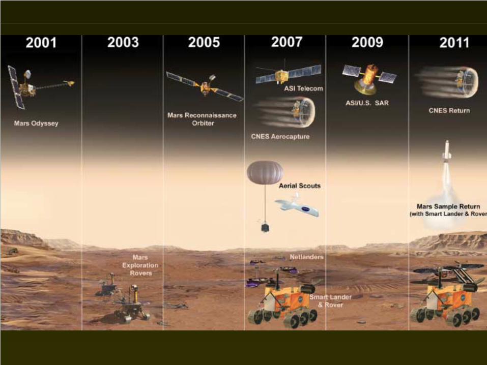
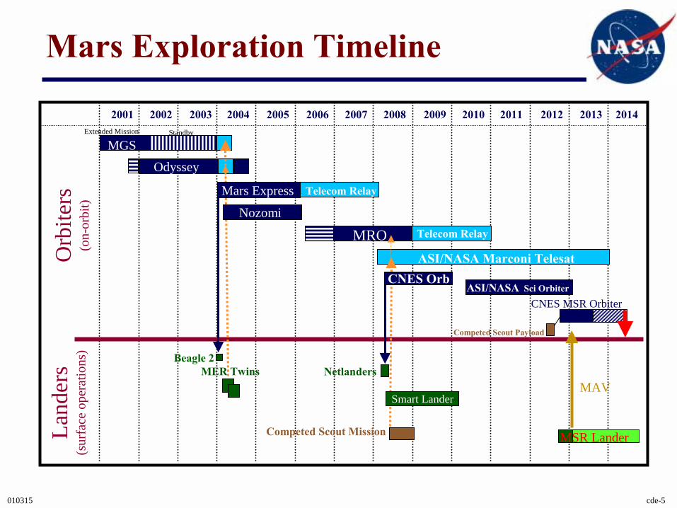
Mars Exploration Timeline
2001 2002 2003 2004 2005 2006 2007 2008 2009 2010 2011 2012 2013 2014
MGS
Telecom Relay
Telecom Relay
ASI/NASA Marconi Telesat
MER Twins Netlanders
MSR Lander
Competed Scout Payload
ASI/NASA Sci Orbiter
MAV
MRO
Beagle 2
Orb
iters
(on-
orbi
t)La
nder
s(s
urfa
ce o
pera
tions
)
Competed Scout Mission
CNES MSR Orbiter
Nozomi
Mars Express
Odyssey
Extended Mission Standby
CNES Orb
Smart Lander
010315 cde-6
Program Drivers on Comm/Nav Infrastructure• Increased science data return (e.g., for multi-spectral surface
pancam imagery)• Complexity of MSR surface operations, with the resulting need for
frequent command cycles and rapid, low-latency engineering data return to support operations planning
• Robust, high-accuracy radio-based approach navigation (e.g., ~<1 km entry knowledge for aerocapture or precision landing)
• Capture of real time engineering telemetry during critical events such as EDL, aeromaneuvering, MAV launch, etc., for feed-forward fault diagnosis in the event of anomaly
• Energy-efficient relay telecommunications for energy- and mass-constrained scout-class missions
• Radio tracking of orbiting sample canister to support in-orbit sample rendezvous
• Surface position determination to support long-range rover navigation
010315 cde-7
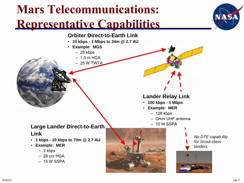
Mars Telecommunications: Representative Capabilities
Orbiter Direct-to-Earth Link� 10 kbps - 1 Mbps to 34m @ 2.7 AU� Example: MGS
� 25 kbps� 1.5 m HGA� 25 W TWTA
Large Lander Direct-to-Earth Link� 1 kbps - 10 kbps to 70m @ 2.7 AU� Example: MER
� 2 kbps� 28 cm HGA� 15 W SSPA
Lander Relay Link� 100 kbps - 1 Mbps� Example: MER
� 128 kbps� Omni UHF antenna� 10 W SSPA
No DTE capab ility for Scout-class landers
010315 cde-8
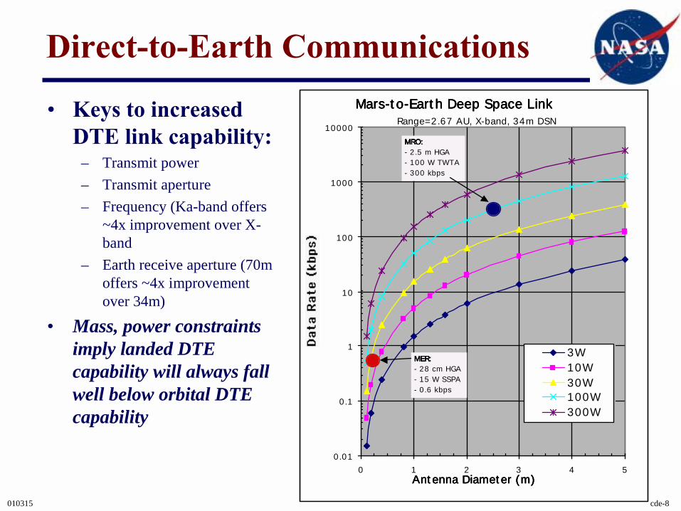
Direct-to-Earth Communications
• Keys to increased DTE link capability:
– Transmit power– Transmit aperture– Frequency (Ka-band offers
~4x improvement over X-band
– Earth receive aperture (70m offers ~4x improvement over 34m)
• Mass, power constraints imply landed DTE capability will always fall well below orbital DTE capability
Mars-to-Earth Deep Space LinkMars-to-Earth Deep Space LinkMars-to-Earth Deep Space LinkMars-to-Earth Deep Space Link
0.01
0.1
1
10
100
1000
10000
0 1 2 3 4 5Antenna Diameter (m) Antenna Diameter (m) Antenna Diameter (m) Antenna Diameter (m)
3W10W30W100W300W
Range=2.67 AU, X-band, 34m DSN
MRO:MRO:MRO:MRO:- 2.5 m HGA- 100 W TWTA- 300 kbps
MER:MER:MER:MER:- 28 cm HGA- 15 W SSPA- 0.6 kbps
010315 cde-9
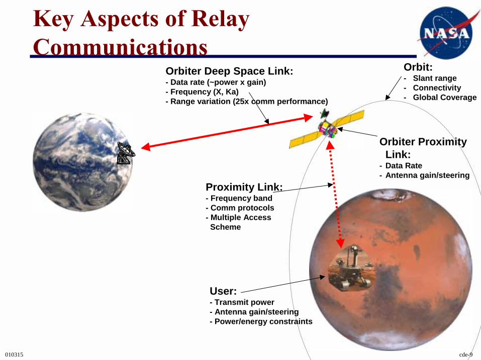
Key Aspects of Relay Communications
User:- Transmit power- Antenna gain/steering- Power/energy constraints
Proximity Link:- Frequency band- Comm protocols- Multiple Access
Scheme
Orbiter Deep Space Link:- Data rate (~power x gain)- Frequency (X, Ka)- Range variation (25x comm performance)
Orbiter Proximity Link:
- Data Rate- Antenna gain/steering
Orbit:- Slant range- Connectivity- Global Coverage
010315 cde-10
Proximity Link Characterisitics• Omni-to-omni links
– Simple ops for lander and orbiter– Link performance scales as 1/freq2
– Current ~400 MHz UHF band represents balance between link performance and RF component size
• Omni-to-directional links– Increased orbiter antenna gain can significantly improve link performance – To first order, for fixed orbiter aperture size, link performance is
frequency-independent– However, orbiter antenna pointing requirements scale with frequency
• Directional-to-directional links– Opens possibility for very high link performance, event over long slant-
range links– Requires antenna pointing at both ends of link
– Link performance scales as freq2
010315 cde-11
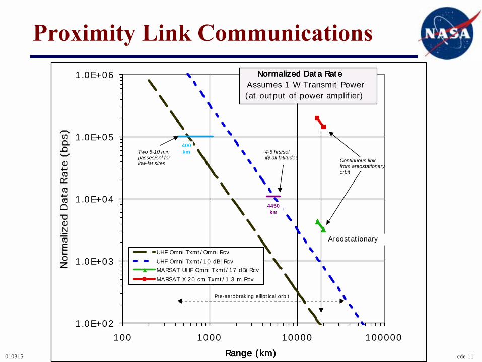
Proximity Link Communications
1.0E+02
1.0E+03
1.0E+04
1.0E+05
1.0E+06
100 1000 10000 100000
Range (km)Range (km)Range (km)Range (km)
UHF Omni Txmt/Omni Rcv
UHF Omni Txmt/10 dBi Rcv
MARSAT UHF Omni Txmt/17 dBi Rcv
MARSAT X 20 cm Txmt/1.3 m Rcv
Areostationary
Pre-aerobraking elliptical orbit
Continuous link from areostationaryorbit
Normalized Data RateNormalized Data RateNormalized Data RateNormalized Data RateAssumes 1 W Transmit Power(at output of power amplifier)
400kmTwo 5-10 min
passes/sol forlow-lat sites
4450km
4-5 hrs/sol@ all latitudes
010315 cde-12
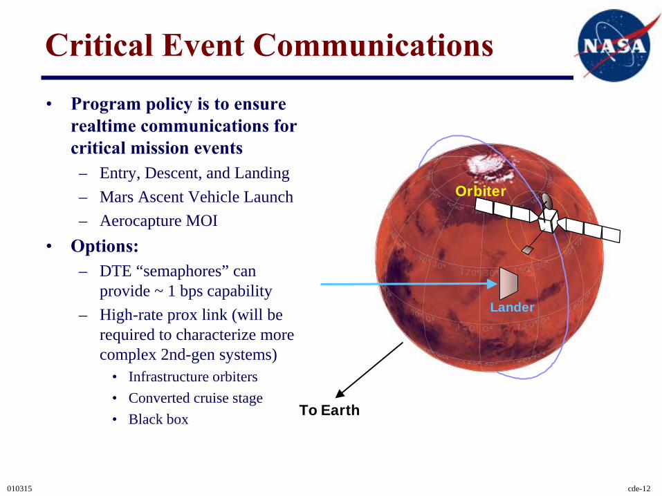
Critical Event Communications
Sun SPK
Mars01
To Earth
Orbiter
Lander
• Program policy is to ensure realtime communications for critical mission events– Entry, Descent, and Landing– Mars Ascent Vehicle Launch– Aerocapture MOI
• Options:– DTE “semaphores” can
provide ~ 1 bps capability– High-rate prox link (will be
required to characterize more complex 2nd-gen systems)
• Infrastructure orbiters• Converted cruise stage• Black box
010315 cde-13
Orbit Changes for EDL SupportOrbit Changes for EDL SupportOrbit Changes for EDL SupportOrbit Changes for EDL Support
0.01
0.1
1
10
100
1000
10000
100000
0100200300400500600700
Time Interval (days)Time Interval (days)Time Interval (days)Time Interval (days)
180 deg In-OrbitPhasing6-hr Local TimeNodal Plane Change
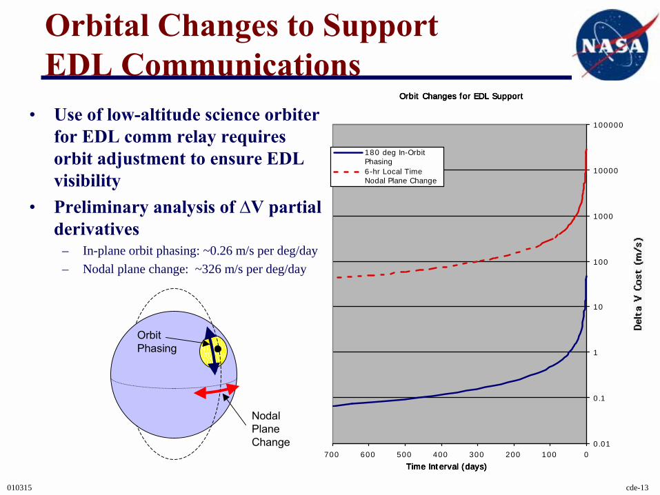
Orbital Changes to Support EDL Communications
NodalPlaneChange
OrbitPhasing
• Use of low-altitude science orbiter for EDL comm relay requires orbit adjustment to ensure EDL visibility
• Preliminary analysis of ∆V partial derivatives
– In-plane orbit phasing: ~0.26 m/s per deg/day– Nodal plane change: ~326 m/s per deg/day
010315 cde-14
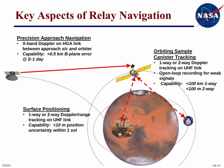
Key Aspects of Relay Navigation
Precision Approach Navigation� X-band Doppler on HGA link
between approach s/c and orbiter� Capability: <0.5 km B-plane error
@ E-1 day
Orbiting Sample Canister Tracking� 1-way or 2-way Doppler
tracking on UHF link� Open-loop recording for weak
signals� Capability: <100 km 1-way
<100 m 2-way
Surface Positioning� 1-way or 2-way Doppler/range
tracking on UHF link� Capability: <10 m position
uncertainty within 1 sol
010315 cde-15
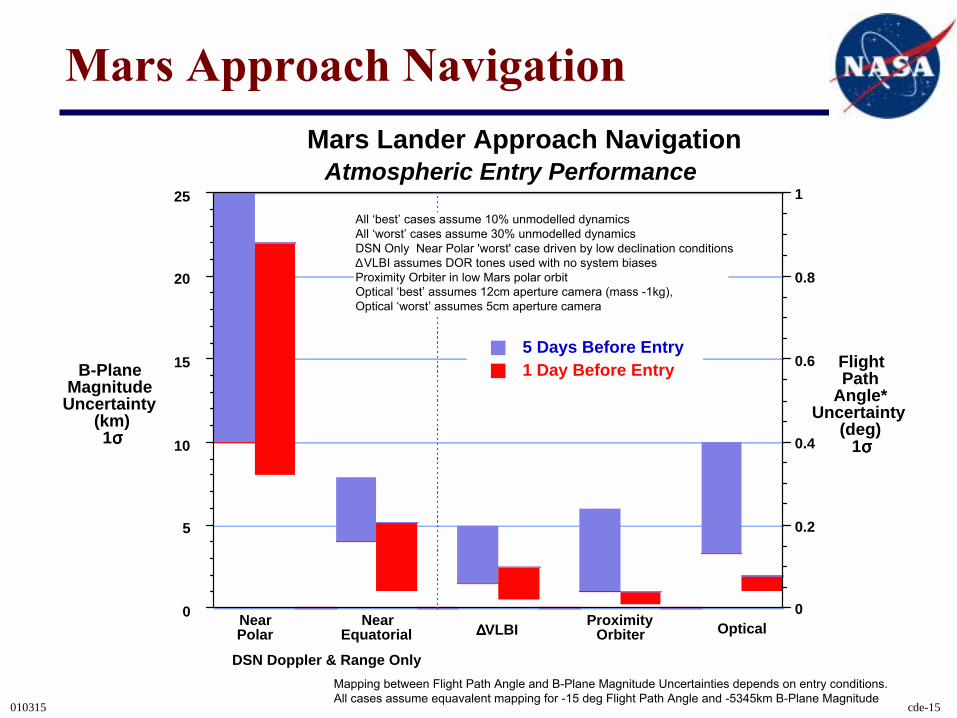
Mars Approach Navigation
0
5
10
15
20
25
Mars Lander Approach Navigation
5 Days Before Entry1 Day Before Entry
0
0.2
0.4
0.6
0.8
1
B-PlaneMagnitude
Uncertainty(km)1σσσσ
DSN Doppler & Range Only
NearPolar
NearEquatorial ∆∆∆∆VLBI Proximity
Orbiter Optical
Atmospheric Entry Performance
FlightPath
Angle*Uncertainty
(deg)1σσσσ
All �best� cases assume 10% unmodelled dynamicsAll �worst� cases assume 30% unmodelled dynamicsDSN Only Near Polar 'worst' case driven by low declination conditions∆VLBI assumes DOR tones used with no system biasesProximity Orbiter in low Mars polar orbitOptical �best� assumes 12cm aperture camera (mass -1kg),Optical �worst� assumes 5cm aperture camera
Mapping between Flight Path Angle and B-Plane Magnitude Uncertainties depends on entry conditions.All cases assume equavalent mapping for -15 deg Flight Path Angle and -5345km B-Plane Magnitude
010315 cde-16
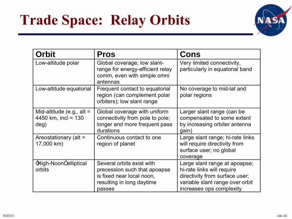
Trade Space: Relay Orbits
Orbit Pros ConsLow-altitude polar Global coverage; low slant-
range for energy-efficient relaycomm, even with simple omniantennas
Very limited connectivity,particularly in equatorial band
Low-altitude equatorial Frequent contact to equatorialregion (can complement polarorbiters); low slant range
No coverage to mid-lat andpolar regions
Mid-altitude (e.g., alt =4450 km, incl = 130deg)
Global coverage with uniformconnectivity from pole to pole;longer and more frequent passdurations
Larger slant range (can becompensated to some extentby increasing orbiter antennagain)
Areostationary (alt =17,000 km)
Continuous contact to oneregion of planet
Large slant range; hi-rate linkswill require directivity fromsurface user; no globalcoverage
ÒHigh-NoonÓ ellipticalorbits
Several orbits exist withprecession such that apoapseis fixed near local noon,resulting in long daytimepasses
Large slant range at apoapse;hi-rate links will requiredirectivity from surface user;variable slant range over orbitincreases ops complexity
010315 cde-17
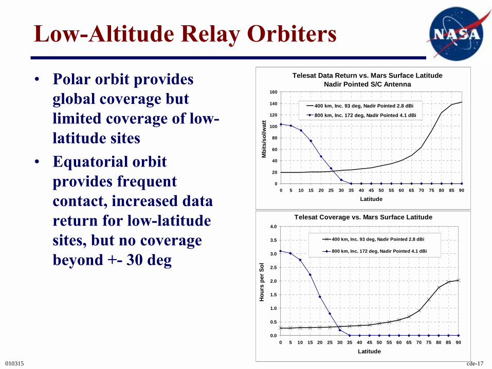
Low-Altitude Relay Orbiters
• Polar orbit provides global coverage but limited coverage of low-latitude sites
• Equatorial orbit provides frequent contact, increased data return for low-latitude sites, but no coverage beyond +- 30 deg
Telesat Coverage vs. Mars Surface Latitude
0.0
0.5
1.0
1.5
2.0
2.5
3.0
3.5
4.0
0 5 10 15 20 25 30 35 40 45 50 55 60 65 70 75 80 85 90
Latitude
Hou
rs p
er S
ol
400 km, Inc. 93 deg, Nadir Pointed 2.8 dBi
800 km, Inc. 172 deg, Nadir Pointed 4.1 dBi
Telesat Data Return vs. Mars Surface LatitudeNadir Pointed S/C Antenna
0
20
40
60
80
100
120
140
160
0 5 10 15 20 25 30 35 40 45 50 55 60 65 70 75 80 85 90
Latitude
Mbi
ts/s
ol/w
att
400 km, Inc. 93 deg, Nadir Pointed 2.8 dBi
800 km, Inc. 172 deg, Nadir Pointed 4.1 dBi
010315 cde-18
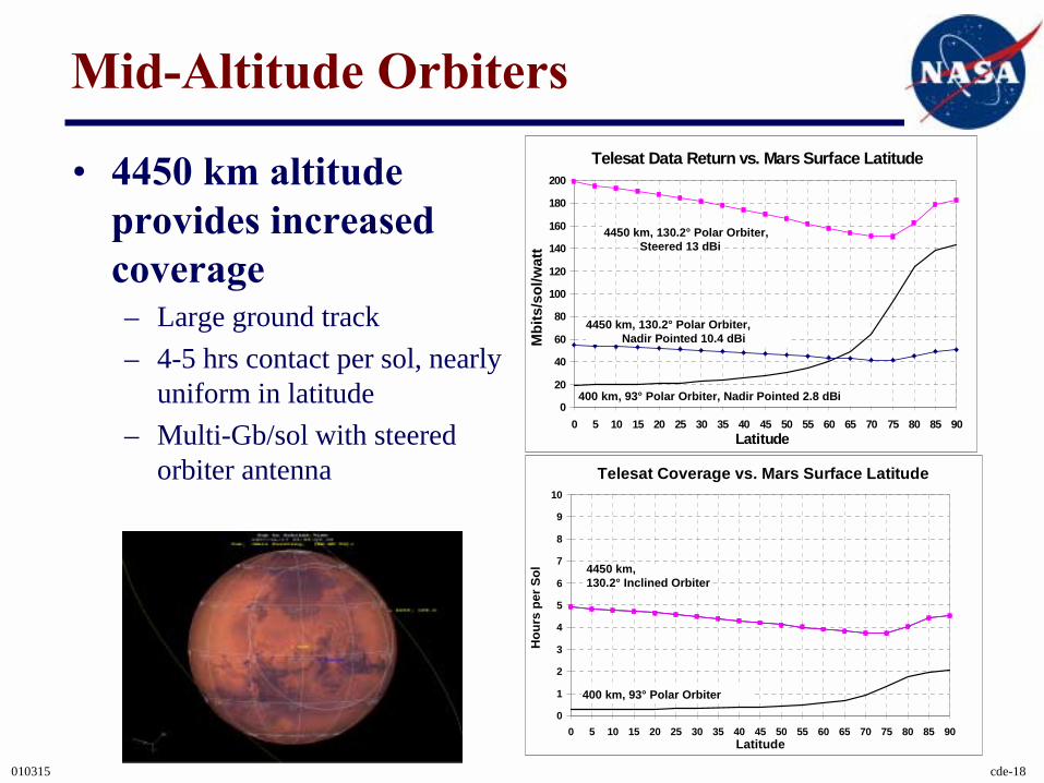
Mid-Altitude Orbiters
• 4450 km altitude provides increased coverage– Large ground track– 4-5 hrs contact per sol, nearly
uniform in latitude– Multi-Gb/sol with steered
orbiter antenna
Telesat Data Return vs. Mars Surface Latitude
0
20
40
60
80
100
120
140
160
180
200
0 5 10 15 20 25 30 35 40 45 50 55 60 65 70 75 80 85 90Latitude
Mbi
ts/s
ol/w
att
400 km, 93° Polar Orbiter, Nadir Pointed 2.8 dBi
4450 km, 130.2° Polar Orbiter, Nadir Pointed 10.4 dBi
4450 km, 130.2° Polar Orbiter, Steered 13 dBi
Telesat Coverage vs. Mars Surface Latitude
0
1
2
3
4
5
6
7
8
9
10
0 5 10 15 20 25 30 35 40 45 50 55 60 65 70 75 80 85 90Latitude
Hou
rs p
er S
ol
400 km, 93° Polar Orbiter
4450 km, 130.2° Inclined Orbiter
010315 cde-19
Areostationary and Highly Elliptical Orbiters• Areostationary
– 17,000 km altitude– Continuous view of one region of planet (~25% of planet centered
about sub-satellite point; no view of polar regions)– High-rate (~1 Mbps) continuous relay to Earth with directional
surface antenna (satellite at fixed point on sky w.r.t. surface user)– Lower-rate (~10 kbps) continuous relay to Earth with simple omni
surface antenna
• HEO– Several “sun-sync” orbits exist with apoapse at a fixed local time
(e.g., local noon); long daytime passes– Large slant range at apoapse -> similar link considerations as for
areo: directional surface antenna req’d for high rate (but now satellite moves on sky w.r.t. surface user)
010315 cde-20
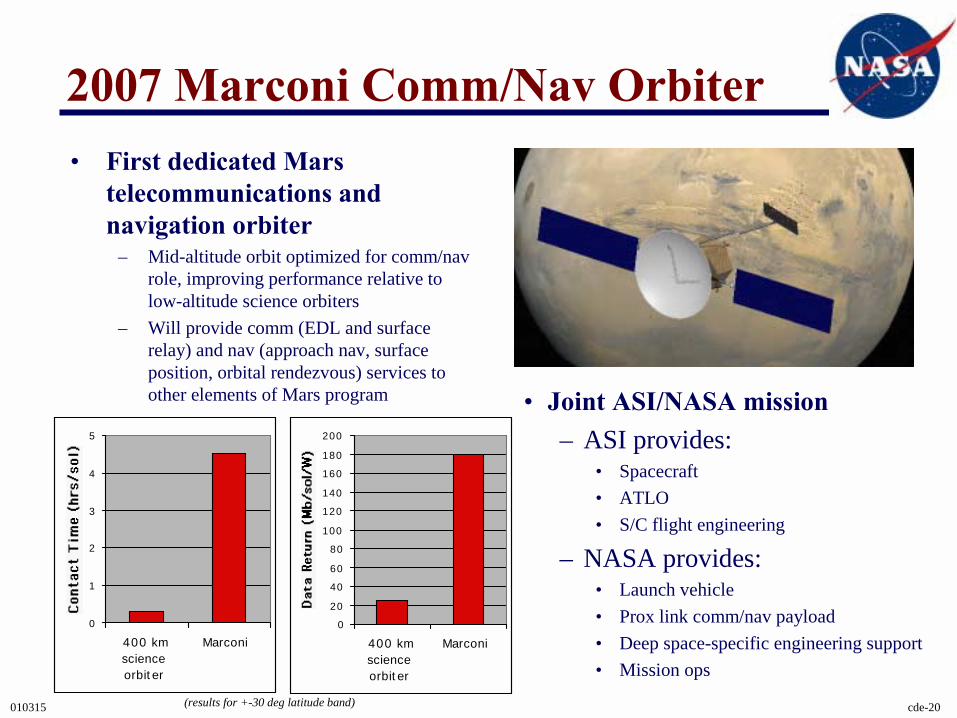
2007 Marconi Comm/Nav Orbiter
• Joint ASI/NASA mission– ASI provides:
• Spacecraft• ATLO• S/C flight engineering
– NASA provides:• Launch vehicle• Prox link comm/nav payload• Deep space-specific engineering support• Mission ops
• First dedicated Mars telecommunications and navigation orbiter
– Mid-altitude orbit optimized for comm/nav role, improving performance relative to low-altitude science orbiters
– Will provide comm (EDL and surface relay) and nav (approach nav, surface position, orbital rendezvous) services to other elements of Mars program
0
1
2
3
4
5
400 kmscienceorbiter
Marconi
0
20
40
60
80
100
120
140
160
180
200
400 kmscienceorbiter
Marconi
(results for +-30 deg latitude band)
010315 cde-21
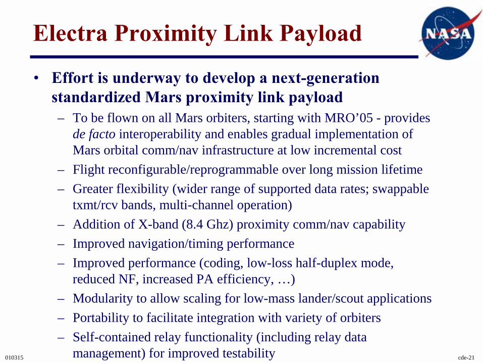
Electra Proximity Link Payload
• Effort is underway to develop a next-generation standardized Mars proximity link payload– To be flown on all Mars orbiters, starting with MRO’05 - provides
de facto interoperability and enables gradual implementation of Mars orbital comm/nav infrastructure at low incremental cost
– Flight reconfigurable/reprogrammable over long mission lifetime– Greater flexibility (wider range of supported data rates; swappable
txmt/rcv bands, multi-channel operation)– Addition of X-band (8.4 Ghz) proximity comm/nav capability– Improved navigation/timing performance– Improved performance (coding, low-loss half-duplex mode,
reduced NF, increased PA efficiency, …)– Modularity to allow scaling for low-mass lander/scout applications– Portability to facilitate integration with variety of orbiters– Self-contained relay functionality (including relay data
management) for improved testability
010315 cde-22
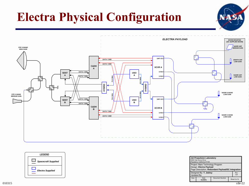
Electra Physical Configuration
SDSTA
SDSTB
C&DHA
C&DHB
DATA / CMD
DATA / CMD
DATA / CMD
DATA / CMD
USOA
USOB
HYB
RID
XCVR A
XCVR B70
.X M
Hz
70.X
MH
z
XX.X
MH
zXX
.X M
Hz
DATA / CMD
DATA / CMD
DATA / CMD
DATA / CMD
UHF XCV
X RCV
UHF XCV
X RCVNADIR X-BAND
LOW GAIN
DTE X-BANDMEDIUM GAIN
DTE X-BANDHIGH GAIN
ELECTRA PAYLOAD
S RCV
S RCV
NADIR S-BANDLOW GAIN
NADIR UHFMEDIUM GAIN
ZENITH UHFLOW GAIN
NADIR UHFLOW GAIN
BOOM MOUNTED(S/C SUPPLIED BOOM)
HYB
RID
LEGEND
Spacecraft Supplied
Electra Supplied
Jet Propulsion Laboratory4800 Oak Grove DrivePasadena, California 91109
Project: Mars Technology ProgramDesign: Electra PayloadPage Description: Redundant Payload/SC IntegrationDesigned By: T. JedreyUpdated By:
Rev1.0
Size Date01/29/01
Document NumberSheet 1 of 1
010315 cde-23
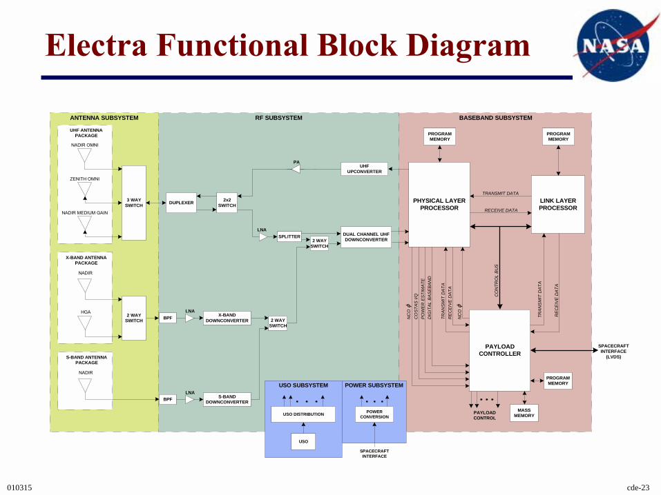
Electra Functional Block Diagram
3 WAYSWITCH
NADIR OMNI
ZENITH OMNI
NADIR MEDIUM GAIN
UHF ANTENNAPACKAGE
DUPLEXER 2x2SWITCH
NADIR
HGA
X-BAND ANTENNAPACKAGE
2 WAYSWITCH BPF X-BAND
DOWNCONVERTER
UHFUPCONVERTER
2 WAYSWITCH
LNA
LNADUAL CHANNEL UHFDOWNCONVERTER
PHYSICAL LAYERPROCESSOR
LINK LAYERPROCESSOR
PAYLOADCONTROLLER
TRANSMIT DATA
RECEIVE DATA
CO
NTR
OL
BU
S
TRAN
SM
IT D
ATA
REC
EIVE
DAT
A
SPACECRAFTINTERFACE
(LVDS)
PROGRAMMEMORY
PROGRAMMEMORY
PROGRAMMEMORY
MASSMEMORY
PA
SPLITTER
PAYLOADCONTROL
2 WAYSWITCH
NADIR
S-BAND ANTENNAPACKAGE
BPF S-BANDDOWNCONVERTER
LNA
ANTENNA SUBSYSTEM RF SUBSYSTEM BASEBAND SUBSYSTEM
NC
O ϕ
CO
STAS
I/Q
POW
ER E
STIM
ATE
DIG
ITAL
BAS
EBAN
D
NC
O ϕ
TRAN
SMIT
DAT
AR
EC
EIVE
DAT
A
USO SUBSYSTEM
USO
USO DISTRIBUTION
POWER SUBSYSTEM
POWERCONVERSION
SPACECRAFTINTERFACE
010315 cde-24
Protocols
• CCSDS Proximity-1 Space Link Protocol – Provides standards for the physical and data link layers for Mars
proximity communications– First implementation on Mars Odyssey– Will be key for achieving interoperability among MER A/B,
Beagle 2, Mars Exp, Odyssey
• CCSDS File Delivery Protocol– Provides reliable end-to-end file delivery– Addresses unique aspects of deep space communications
• Long RTLT• Intermittent connectivity• High BER links• Multi-hop store-and-forward relays• Custody transfer to minimize onboard storage rqmts
010315 cde-25
Key Technologies
• The Mars Technology Program is funding a number of important comm/nav technology task:– Deep Space Communications
• High-EIRP RF Technologies (B. Lovick)• Optical Comm Flight Demo (K. Wilson)
– Mars Proximity Communications• Electra Advanced Development (T. Jedrey)• UHF Antennas (K. Kelly)
– Radio-Based Navigation• ST5 Flight Demo (W. Bertiger)• In Situ Navigation (J. Guinn)
– Communications Protocols and Coding• Proximity Link Protocols (L. Clare)
010315 cde-26
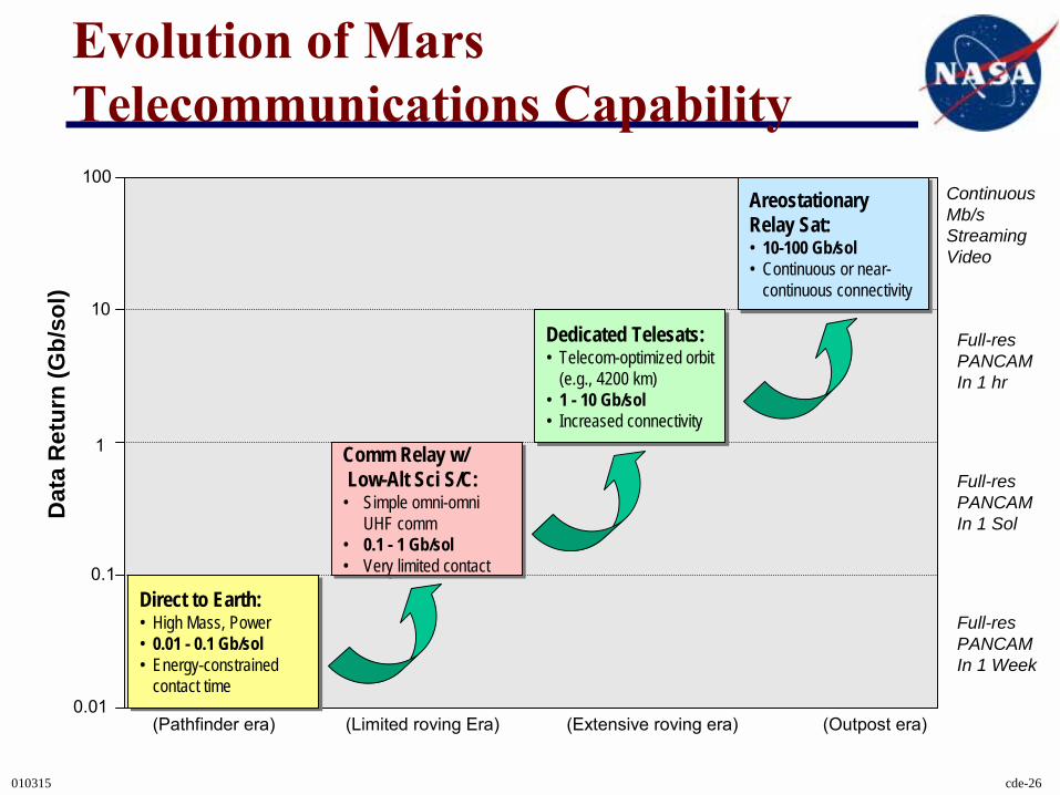
Evolution of Mars Telecommunications Capability
1
10
100
0.1
0.01
Dat
a R
etur
n (G
b/so
l)
Direct to Earth:• High Mass, Power• 0.01 - 0.1 Gb/sol• Energy-constrained
contact time
Direct to Earth:• High Mass, Power• 0.01 - 0.1 Gb/sol• Energy-constrained
contact time
Comm Relay w/Low-Alt Sci S/C:
• Simple omni-omni UHF comm
• 0.1 - 1 Gb/sol• Very limited contact
Comm Relay w/Low-Alt Sci S/C:
• Simple omni-omni UHF comm
• 0.1 - 1 Gb/sol• Very limited contact
Dedicated Telesats:• Telecom-optimized orbit
(e.g., 4200 km)• 1 - 10 Gb/sol• Increased connectivity
Dedicated Telesats:• Telecom-optimized orbit
(e.g., 4200 km)• 1 - 10 Gb/sol• Increased connectivity
AreostationaryRelay Sat:• 10-100 Gb/sol• Continuous or near-
continuous connectivity
AreostationaryRelay Sat:• 10-100 Gb/sol• Continuous or near-
continuous connectivity
(Pathfinder era) (Limited roving Era) (Outpost era)(Extensive roving era)
ContinuousMb/s StreamingVideo
Full-resPANCAMIn 1 Sol
Full-resPANCAMIn 1 Week
Full-resPANCAMIn 1 hr
010315 cde-27
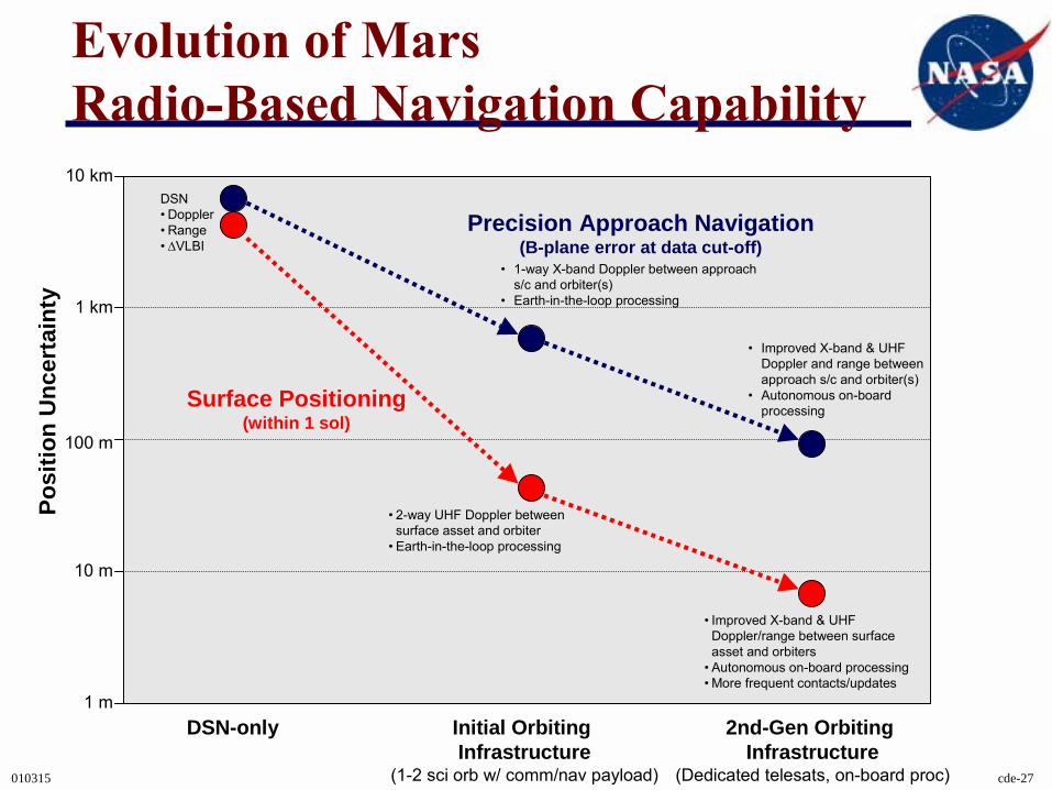
Evolution of Mars Radio-Based Navigation Capability
100 m
1 km
10 km
10 m
1 m
Posi
tion
Unc
erta
inty
DSN-only Initial Orbiting Infrastructure
(1-2 sci orb w/ comm/nav payload)
2nd-Gen Orbiting Infrastructure
(Dedicated telesats, on-board proc)
Precision Approach Navigation(B-plane error at data cut-off)
Surface Positioning(within 1 sol)
DSN� Doppler� Range� ∆VLBI
� 1-way X-band Doppler between approach s/c and orbiter(s)
� Earth-in-the-loop processing
� Improved X-band & UHF Doppler and range between approach s/c and orbiter(s)
� Autonomous on-board processing
� 2-way UHF Doppler between surface asset and orbiter
� Earth-in-the-loop processing
� Improved X-band & UHF Doppler/range between surface asset and orbiters
� Autonomous on-board processing� More frequent contacts/updates
010315 cde-28
Some Parting Questions...• How do we manage and operate a heterogenous collection of
orbital relay spacecraft as an integrated Mars comm/nav infrastructure?
• What is the science value of increased bandwidth and connectivity? – How would a continuous high-rate areostationary relay change our surface
operations concepts?• When is it cost-effective to transition to:
– Demand access proximity service concept?– On-board radiometric data processing?– Higher-frequency directional lander links?
• How should our proximity link standards evolve?– Physical layer– Modulation and coding– Higher layers of data management– Ultimate interface with IPN vision
A Real-World Example: MER EDL Communications
010315 cde-30
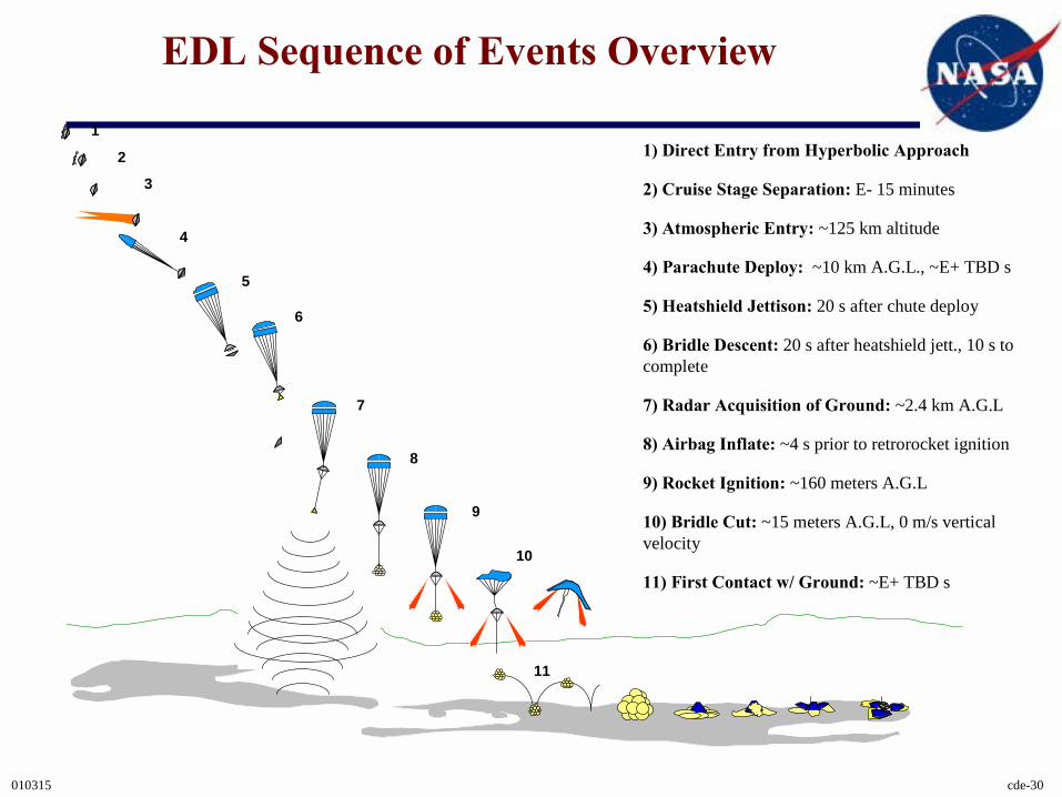
EDL Sequence of Events Overview
1) Direct Entry from Hyperbolic Approach
2) Cruise Stage Separation: E- 15 minutes
3) Atmospheric Entry: ~125 km altitude
4) Parachute Deploy: ~10 km A.G.L., ~E+ TBD s
5) Heatshield Jettison: 20 s after chute deploy
6) Bridle Descent: 20 s after heatshield jett., 10 s to complete
7) Radar Acquisition of Ground: ~2.4 km A.G.L
8) Airbag Inflate: ~4 s prior to retrorocket ignition
9) Rocket Ignition: ~160 meters A.G.L
10) Bridle Cut: ~15 meters A.G.L, 0 m/s vertical velocity
11) First Contact w/ Ground: ~E+ TBD s
1
2
3
4
5
6
8
7
9
10
11
010315 cde-31
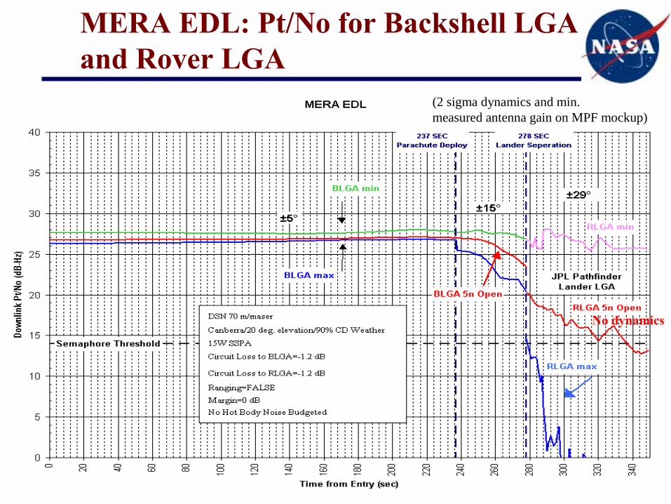
MERA EDL: Pt/No for Backshell LGA and Rover LGA
(2 sigma dynamics and min. measured antenna gain on MPF mockup)
No dynamics
010315 cde-32
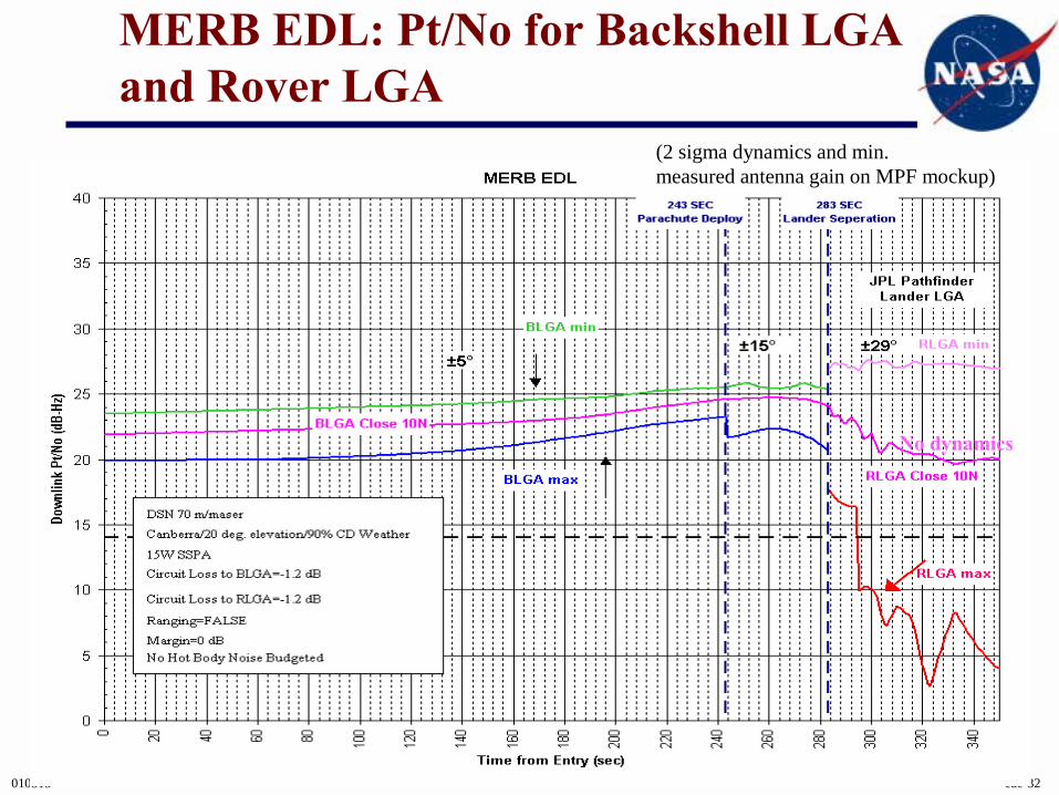
No dynamics
MERB EDL: Pt/No for Backshell LGA and Rover LGA
(2 sigma dynamics and min. measured antenna gain on MPF mockup)
010315 cde-33
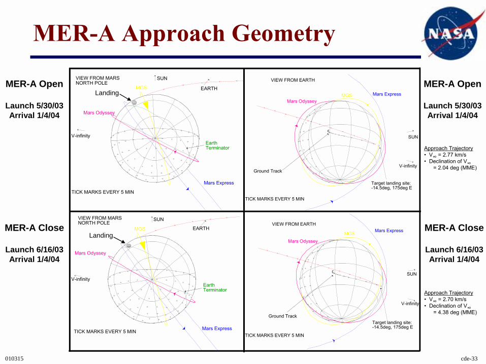
MER-A Approach Geometry
Approach Trajectory� V∞ = 2.77 km/s � Declination of V∞
= 2.04 deg (MME)
Approach Trajectory� V∞ = 2.70 km/s � Declination of V∞
= 4.38 deg (MME)
MER-A Open
Launch 5/30/03Arrival 1/4/04
MER-A Open
Launch 5/30/03Arrival 1/4/04
MER-A Close
Launch 6/16/03Arrival 1/4/04
MER-A Close
Launch 6/16/03Arrival 1/4/04
VIEW FROM MARS NORTH POLE
EARTH
Earth Terminator
Mars Express
Mars Odyssey
V-infinity
SUN
TICK MARKS EVERY 5 MIN
MGSMars Express
Mars Odyssey
Ground TrackV-infinity
SUN
TICK MARKS EVERY 5 MIN
VIEW FROM EARTH
Target landing site: -14.5deg, 175deg E
MGS
VIEW FROM MARS NORTH POLE
EARTH
Earth Terminator
Mars Express
Mars Odyssey
V-infinity
SUN
TICK MARKS EVERY 5 MIN
MGS Mars Express
Mars Odyssey
Ground Track
V-infinity
SUN
TICK MARKS EVERY 5 MIN
VIEW FROM EARTH
Target landing site: -14.5deg, 175deg E
MGS
Landing
Landing
010315 cde-34
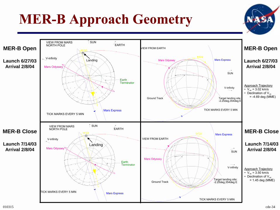
MER-B Approach Geometry
Approach Trajectory� V∞ = 3.02 km/s � Declination of V∞
= -4.69 deg (MME)
Approach Trajectory� V∞ = 3.50 km/s � Declination of V∞
= 1.45 deg (MME)
MER-B Open
Launch 6/27/03Arrival 2/8/04
MER-B Open
Launch 6/27/03Arrival 2/8/04
MER-B Close
Launch 7/14/03Arrival 2/8/04
MER-B Close
Launch 7/14/03Arrival 2/8/04
VIEW FROM MARS NORTH POLE EARTH
Earth Terminator
Mars Express
V-infinity
SUN
TICK MARKS EVERY 5 MIN
Mars Odyssey
MGS
Mars ExpressMars Odyssey
Ground Track
V-infinity
SUN
TICK MARKS EVERY 5 MIN
VIEW FROM EARTH
Target landing site: -2.25deg,354deg E
MGS
VIEW FROM MARS NORTH POLE EARTH
Earth Terminator
Mars Express
V-infinity
SUN
TICK MARKS EVERY 5 MIN
Mars Odyssey
MGS Mars Express
Mars Odyssey
Ground Track
V-infinity
SUN
TICK MARKS EVERY 5 MIN
VIEW FROM EARTH
Target landing site: -2.25deg,354deg E
MGS
Landing
Landing
010315 cde-35
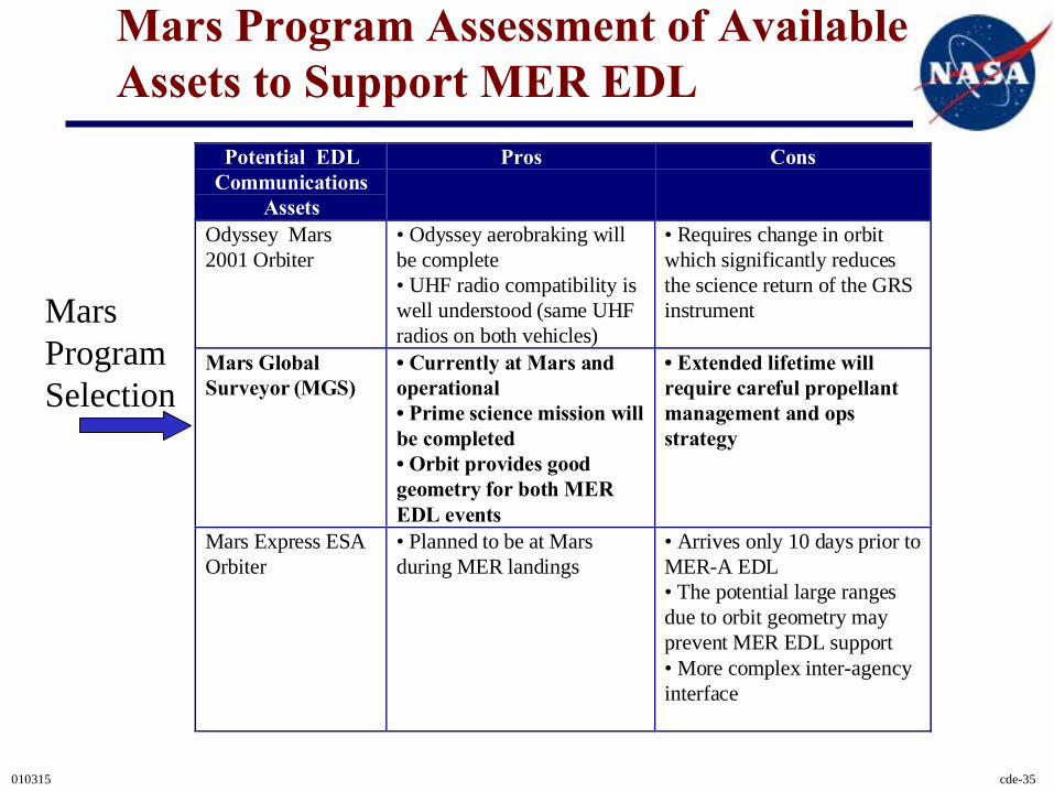
Mars Program Assessment of Available Assets to Support MER EDL
Mars ProgramSelection
Potential EDLCommunications
Assets
Pros Cons
Odyssey Mars2001 Orbiter
• Odyssey aerobraking willbe complete• UHF radio compatibility iswell understood (same UHFradios on both vehicles)
• Requires change in orbitwhich significantly reducesthe science return of the GRSinstrument
Mars GlobalSurveyor (MGS)
� Currently at Mars andoperational� Prime science mission willbe completed� Orbit provides goodgeometry for both MEREDL events
� Extended lifetime willrequire careful propellantmanagement and opsstrategy
Mars Express ESAOrbiter
• Planned to be at Marsduring MER landings
• Arrives only 10 days prior toMER-A EDL• The potential large rangesdue to orbit geometry mayprevent MER EDL support• More complex inter-agencyinterface