the cause of iridescence in rainbow andradite from nara, japan · using a custom-made sas2000...
TRANSCRIPT

arnets with optical phenomena are notcommonly encountered, although severaltypes are known, including color-change,
star, cat’s-eye, and, rarely, iridescent garnets. Color-change garnets are usually pyrope-spessartine,while star garnets are generally almandine orpyrope-almandine. Iridescence in garnet is knownonly in andradite and grossular-andradite (alsocalled “grandite”).
These iridescent garnets are mainly known fromSonora, Mexico (see Koivula, 1987; Koivula andKammerling, 1988; Badar and Akizuki, 1997; Boehm,2006). They were initially described several decadesago from a locality in Nevada (Ingerson andBarksdale, 1943); the same authors mentioned simi-lar andradites from Japan (Kamihoki, YamaguchiPrefecture, Chugoku Region, Honshu Island).Iridescent garnet from Japan’s Nara Prefecture (figure1) was discovered in 2004, and the material has beendescribed by Shimobayashi et al. (2005). More recent-ly, iridescent andradite was found in New Mexico(Burger, 2005). The purpose of this article is todescribe the new iridescent garnet from Japan and toattempt a detailed explanation of the color phe-nomenon observed in this attractive material.
LOCATION, GEOLOGY, MINING, AND PRODUCTION“Rainbow” andradite from Nara Prefecture was firstrecovered in early 2004 by several groups of mineralcollectors near the old Kouse magnetite mine atTenkawa in the Yoshino area (Y. Sakon, pers.comm., 2005). This region lies approximately 60km southeast of Osaka, and is about 400 km east ofthe Kamihoki locality described by Ingerson andBarksdale (1943; figure 2). Rocks in this area formpart of the regional metamorphic Chichibu belt,which lies just south of the Sanbagawa belt(Takeuchi, 1996).
The first garnets recovered were not of highquality, but in September 2004 a local mineral col-lector (J. Sugimori) found an outcrop containinggem-quality andradite (i.e., strongly iridescent andrelatively “clean” material). Over the next fourmonths, he used hand tools to follow the vein to
248 IRIDESCENCE IN RAINBOW ANDRADITE FROM JAPAN GEMS & GEMOLOGY WINTER 2006
G
THE CAUSE OF IRIDESCENCE INRAINBOW ANDRADITEFROM NARA, JAPAN
Thomas Hainschwang and Franck Notari
See end of article for About the Authors and Acknowledgments.GEMS & GEMOLOGY, Vol. 42, No. 4, pp. 248–258.© 2006 Gemological Institute of America
“Rainbow” andradite from Nara, Japan, occurs as relatively small orangy brown crystals thatshow attractive iridescence in almost the entire range of the spectrum. The material is nearlypure andradite, as determined by its chemical composition and Vis-NIR and specularreflectance FTIR spectra. Microscopy revealed that two different types of lamellar structuresappear to be responsible for the iridescent colors. These lamellar structures cause predominantlythin-film interference and most likely diffraction of light. The terms interference and diffractionare explained and correlated to the structure and iridescence observed in these garnets.
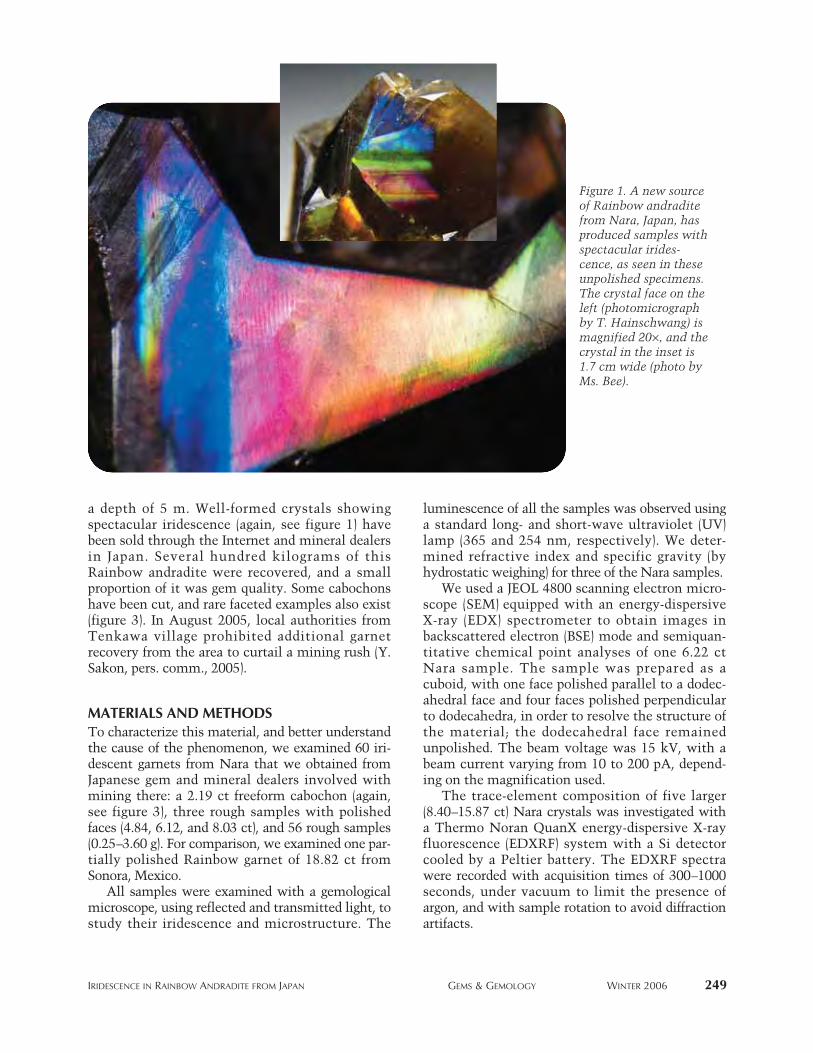
a depth of 5 m. Well-formed crystals showing spectacular iridescence (again, see figure 1) havebeen sold through the Internet and mineral dealersin Japan. Several hundred kilograms of thisRainbow andradite were recovered, and a smallproportion of it was gem quality. Some cabochonshave been cut, and rare faceted examples also exist(figure 3). In August 2005, local authorities fromTenkawa village prohibited additional garnetrecovery from the area to curtail a mining rush (Y.Sakon, pers. comm., 2005).
MATERIALS AND METHODSTo characterize this material, and better understandthe cause of the phenomenon, we examined 60 iri-descent garnets from Nara that we obtained fromJapanese gem and mineral dealers involved withmining there: a 2.19 ct freeform cabochon (again,see figure 3), three rough samples with polishedfaces (4.84, 6.12, and 8.03 ct), and 56 rough samples(0.25–3.60 g). For comparison, we examined one par-tially polished Rainbow garnet of 18.82 ct fromSonora, Mexico.
All samples were examined with a gemologicalmicroscope, using reflected and transmitted light, tostudy their iridescence and microstructure. The
luminescence of all the samples was observed usinga standard long- and short-wave ultraviolet (UV)lamp (365 and 254 nm, respectively). We deter-mined refractive index and specific gravity (byhydrostatic weighing) for three of the Nara samples.
We used a JEOL 4800 scanning electron micro-scope (SEM) equipped with an energy-dispersiveX-ray (EDX) spectrometer to obtain images inbackscattered electron (BSE) mode and semiquan-titative chemical point analyses of one 6.22 ctNara sample. The sample was prepared as acuboid, with one face polished parallel to a dodec-ahedral face and four faces polished perpendicularto dodecahedra, in order to resolve the structure ofthe material; the dodecahedral face remainedunpolished. The beam voltage was 15 kV, with abeam current varying from 10 to 200 pA, depend-ing on the magnification used.
The trace-element composition of five larger(8.40–15.87 ct) Nara crystals was investigated witha Thermo Noran QuanX energy-dispersive X-rayfluorescence (EDXRF) system with a Si detectorcooled by a Peltier battery. The EDXRF spectrawere recorded with acquisition times of 300–1000seconds, under vacuum to limit the presence ofargon, and with sample rotation to avoid diffractionartifacts.
IRIDESCENCE IN RAINBOW ANDRADITE FROM JAPAN GEMS & GEMOLOGY WINTER 2006 249
Figure 1. A new sourceof Rainbow andraditefrom Nara, Japan, hasproduced samples withspectacular irides-cence, as seen in theseunpolished specimens.The crystal face on theleft (photomicrographby T. Hainschwang) ismagnified 20×, and thecrystal in the inset is1.7 cm wide (photo byMs. Bee).

The infrared spectra of five Nara samplesexhibiting smooth crystal faces were recorded at 4cm−1 resolution with a PerkinElmer Spectrum BXIIFTIR spectrometer equipped with a Deuterated Tri-Glycine Sulfate (DTGS) detector. A PerkinElmer
fixed angle specular reflectance accessory was usedfor specular reflectance spectra.
We recorded visible–near infrared (Vis-NIR)absorption spectra in the 400–1000 nm range forthree highly transparent samples and a small trans-
250 IRIDESCENCE IN RAINBOW ANDRADITE FROM JAPAN GEMS & GEMOLOGY WINTER 2006
Figure 3. Both cabochon-cut and faceted Rainbow andradite have been produced, typically in freeform shapes.The cabochon on the left weighs 2.19 ct (photo by T. Hainschwang) and the faceted stones on the right are6.43–11.39 ct (gift of Keiko Suehiro, GIA Collection nos. 36136–36138; photo by C. D. Mengason).
Figure 2. Rainbowandradite from NaraPrefecture was firstrecovered in early 2004from the Tenkawa area,located approximately60 km southeast ofOsaka. This deposit isabout 400 km east ofJapan’s original sourcefor this garnet, nearKamihoki.

IRIDESCENCE IN RAINBOW ANDRADITE FROM JAPAN GEMS & GEMOLOGY WINTER 2006 251
parent chip (in order to resolve the 440 nm band),using a custom-made SAS2000 system equippedwith an Ocean Optics SD2000 dual-channel spec-trometer with a resolution of 1.5 nm. A 2048-ele-ment linear silicon CCD detector was employed.
RESULTSStandard Gemological Testing. All of the Naragarnets had an orangy brown bodycolor, but theyexhibited a variety of iridescent colors. Dependingon the viewing orientation and the particular crys-tal face, the phenomenon varied from a singlecolor to a range of colors that shifted as the facewas moved (see, e.g., figure 4). Some samples alsoexhibited “white” flashes that appeared to resultfrom several overlapping colors due to the com-bined interference from multiple layers.
Microscopic examination indicated the pres-ence of a rather complex lamellar (thin-layered)structure (figure 5). Observation of well-formeddodecahedral crystals demonstrated that the irides-cence-causing lamellae were most probably orient-ed parallel to the dodecahedral {110} faces. Thus,six sets of lamellae were present in these garnets,each parallel to two {110} faces. These lamellaecaused broad flashes of one or two nonspectral col-ors (usually “golden,” pinkish red, and blue-green)visible on the {110} faces, always of a relativelyweak intensity (figure 6). (“Nonspectral” colorsare combinations of spectral colors, which can beseen as a continuous spectral distribution or acombination of primary colors; most colors arenonspectral mixtures.) Brighter and more variedcolors were seen on faces oblique to the {110} faces(again, see figures 1 and 4). These irregular striatedfaces were apparently formed by intergrowth, dis-
tortion, and possibly twinning. According toShimobayashi et al. (2005), the {211} trapezohedralfaces are also present on some of the Nara garnets,but we did not see them on our samples. The iri-descent colors were not only observed on the sur-face of the garnets, but they were also seen deepwithin the more transparent stones.
Besides the lamellar structure parallel to {110},we also observed an irregular, wavy, step-like
Figure 5. A complex lamellar structure was apparentin the garnets. Thin-film lamellae oriented parallel tothe dodecahedral {110} faces formed the predominantmicrostructure of the bright, colorful parallel bands.Photomicrograph by T. Hainschwang; magnified 10×.
Figure 4. Very colorfuland strong iridescence,varying from a range ofspectral colors (left) tobroad flashes of a singlecolor (right), can beseen in the andraditeas the viewing anglechanges. Colors such asthese were seen onfaces oblique to {110}.Photomicrographs by T. Hainschwang; mag-nified 40× (left) and60× (right).

lamellar structure on the dodecahedral faces (figure7), which was more distinct on practically all facesinclined to the dodecahedra. These two types oflamellar structure are apparently unrelated growthphenomena. Shimobayashi et al. (2005) measured aspacing of ~10–20 μm in the wavy structure; how-ever, they did not assign any phenomenon to theselamellae. In contrast, our microscopic observationssuggested that this lamellar structure does play arole in the iridescence, even though the lamellae arerelatively widely spaced, clearly above the spacingof 100–1000 nm required for a thin-film interfer-ence phenomenon (Hirayama et al., 2000). On cer-tain faces, crossed iridescent colors could be seenthat appeared to be caused by both the narrowlamellae and the widely spaced wavy lamellae (fig-ure 8). We believe that the moiré-like patterncaused by these crossed iridescent colors is also theresult of an interference effect: The crossed grids
cause interference and therefore appear distorted. The refractive index of these garnets was above
the limit of the refractometer (>1.81), as expectedfor andradite. The specific gravity varied slightlyfrom 3.79 to 3.82. As expected for iron-bearing gar-nets, the samples were inert to short- and long-waveUV radiation.
EDXRF Chemical Analysis. The EDXRF data con-firmed that these samples were basically the calci-um-iron garnet andradite. Traces of Al and Mn weredetected, which most likely indicated very smallgrossular and spessartine components.
SEM-BSE Imaging and EDX Chemical Analysis.The SEM analysis was performed on a face pol-ished perpendicular to {110}. BSE imaging (figure 9)revealed a structure consisting of fine lamellae (with different chemical compositions) parallel to
252 IRIDESCENCE IN RAINBOW ANDRADITE FROM JAPAN GEMS & GEMOLOGY WINTER 2006
Figure 6. Weak iridescence created broad flashes of nonspectral colors on the dodecahedral {110} faces of theNara andradites. The colors included “golden” and pinkish red (left, 6.44 ct), greenish blue (center, 9.16 ct), and less commonly bluish purple (right, magnified 15×). The photo on the right also shows (at bottom) theintense lamellar iridescence that is oblique to the dodecahedral face. Photos by T. Hainschwang.
Figure 7. In addition tothe fine lamellar struc-tures parallel to {110},coarser-scale, wavy, step-like structures were seenon practically all facesinclined to the dodeca-hedra. They appear toproduce iridescence col-ors through a diffractioneffect. Photomicrographsby T. Hainschwang;magnified 30× (left) and45× (right).

the {110} face. In the BSE image, darker zones areof lower mean atomic number and lighter zonesare of higher mean atomic number.
The lamellae were of varying thicknesses, rang-
ing from about 100 nm to approximately 10 μm;they appeared to average 100–1000 nm (0.1–1 μm).This range is in good agreement with that deter-mined by Shimobayashi et al. (2005).
The semiquantitative EDX chemical point anal-yses performed on darker and lighter lamellae indi-cated higher aluminum and lower iron in the dark-er (lower mean atomic number) zones, whereas thelighter (higher mean atomic number) zones werericher in iron and poorer in aluminum. The darkerzones on the BSE image contained about 1–1.5%less iron than the brighter zones and about thesame or more aluminum. Thus, the brighter lamel-lae were nearly pure andradite (Ca3Fe2[SiO4]3), andthe darker ones were andradite with a slightly ele-vated grossular (Ca3Al2[SiO4]3) component.
The minute spessartine component (i.e., man-ganese) detected by EDXRF analysis was not iden-tified by the SEM-EDX technique, since the con-centration was below the detection limit of theinstrument.
FTIR Spectroscopy. The specular reflectance FTIRspectra indicated that the samples were almostpure andradite (commonly a perfect match withour reference spectrum; see figure 10).
Vis-NIR Spectroscopy. Vis-NIR spectroscopy (fig-ure 11) showed a typical andradite spectrum, with
IRIDESCENCE IN RAINBOW ANDRADITE FROM JAPAN GEMS & GEMOLOGY WINTER 2006 253
Figure 9. In this backscattered electron (BSE) image ofthe fine lamellae parallel to {110}, the brighter zones(with a higher mean atomic number) correspond topure andradite, while the darker zones (with a lowermean atomic number) are andradite with a grossularcomponent. BSE image width ~80 μm.
Figure 10. A comparison of the specular reflectanceFTIR spectra of the Japanese Rainbow garnet withandradite (demantoid) from Russia and grossular (tsa-vorite) from Kenya indicates that the Japanese materi-al is almost pure andradite.
Figure 8. On some of the faces, a moiré pattern wasvisible, which was apparently related to the wavystructure seen on most of the faces of these garnets.The example shown here has overlapping bright pinkto blue to greenish blue iridescence on a face that isoblique to a dodecahedral face. Photomicrograph byT. Hainschwang; magnified 25×.

a distinct absorption at 440 nm and a very broadband centered in the near-infrared range at 860nm, both assigned to Fe3+ (Manning, 1967). Inthicker specimens, the 440 nm absorption couldnot be resolved due to complete absorption start-ing at about 450 nm. In addition, a very weak bandat 480 nm was detected.
DISCUSSIONThe Nara locality in Japan represents the seconddiscovery of a commercial source for attractive iri-descent garnets after Sonora, Mexico. However,the Japanese material appears very different fromthe Mexican garnets, which have a more greenishbodycolor and show lamellar stripe-like irides-cence, sometimes causing a star (figure 12). TheJapanese garnets may resemble some brown opalssuch as those from Ethiopia (e.g., figure 13), andthe iridescence is similar to that of high-qualitylabradorite from Finland.
The iridescence in this Japanese Rainbow andra-dite is caused by their lamellar structure: alternat-ing microscopic layers of slightly different compo-sition and varying width. Some layers are nearlypure andradite, while the others are andradite witha grossular component. The spacing of the layers,as revealed by SEM-BSE imaging, is suitable forthin-film interference of visible light, and diffrac-tion-related interference may occur when light hitsthe edges of these layers. (See box A for a moredetailed discussion of diffraction and interference,
and the distinctions between them.) The chemicaldifferences detected in adjacent layers and the asso-ciated differences in R.I., combined with this finelylayered structure, clearly point toward multilayerthin-film interference as the main cause of the col-orful iridescence.
Both diffraction grating and multilayer interfer-ence structures are present when the garnets areviewed at oblique angles to the dodecahedral faces.This explains why the most intense iridescent col-ors can be observed on faces oblique to {110}. Themuch weaker and less colorful iridescence visible
254 IRIDESCENCE IN RAINBOW ANDRADITE FROM JAPAN GEMS & GEMOLOGY WINTER 2006
Figure 11. The Vis-NIR spectrum of a small transpar-ent chip of Rainbow andradite is characterized byFe3+-related absorptions at 440 and 860 nm, plus aweak broad band at 480 nm. The Fe3+-relatedabsorptions are encountered in all andradite.
Figure 12. Iridescent Mexican “grandite” (grossular-andradite) garnets have a different appearance from the Japanesematerial. The 18.82 ct Mexican garnet shown on the left has a distinct four-rayed star. Its layer-like iridescence (right,magnified 30×) is quite distinct from that of the Japanese Rainbow andradite. Photos by T. Hainschwang.

on {110} faces (figure 6) can be explained by a simplethin-film interference effect.
The other, rather wavy step-like structure visibleon almost all faces is likely not responsible for anycolor dispersion due to thin-film interference,because its spacing is much greater than the wave-length of visible light. However, some weaker iri-descent colors, which overlap the dominant irides-cent colors (figure 7), appear to be caused by adiffraction effect from this structure. This may beexplained by comparison to a planar diffraction grat-ing, which will disperse visible light even with aspacing of 20 gratings/mm (a spacing of 50 μm; see,e.g., Newport Corp., 2006). The wavy lamellae, withtheir step-like surface, could act like a planardiffraction grating having between 50 and 100 grat-ings/mm. Similar effects can be seen with the lowgroove density (less than 87 grooves/mm) present inthe shells of most mollusks; Liu et al. (1999) relatedthese grooves to weak iridescence caused by diffrac-tion. Indeed the more widely spaced, wavy, step-like lamellar structure in the garnets is very remi-niscent of the step-like structure seen in the nacre-ous aragonite layer of shell (Liu et al., 1999;Fengming et al., 2004).
However, shell iridescence has also beendescribed as a mixed-layer interference and diffrac-tion phenomenon (Tan et al., 2004), and as a thin-film interference phenomenon (Fritsch andRossman, 1988). A similar structure consisting ofboth straight lamellae parallel to {110} and wavylamellae has been described in iridescent garnetsfrom the Adelaide mining district, Nevada, byAkizuki et al. (1984). The same authors describedthe lack of this wavy structure in iridescent garnetsfrom Kamihoki, Japan.
Further evidence for a combination of finelamellae and a wavy lamellar (diffraction grating)structure as the cause of iridescence in these gar-
nets is provided by the moiré pattern visible onmany of the faces (again, see figure 8). Moiré pat-terns are caused by interference due to the superpo-sition of two similarly spaced fine patterns, such asgrids; interference on these grids results in theirdistorted appearance, as seen in the two intersect-ing sets of iridescent color lamellae in figure 8. Inthese garnets, we have a total of six sets of straight,narrow multilayer structures (each of them follow-ing two of the 12 {110} faces) plus the larger, wavylamellar structure that does not relate to the dodec-ahedral faces. Thus, on faces oblique to a simple{110} face, several of these structures and their asso-ciated color patterns will overlap and cause verycolorful iridescence.
Combinations of multilayer interference andlamellar diffraction grating structures have beencredited with causing the bright blue iridescenceseen in Morpho didius butterflies (Vukusic et al.,1999; Iwase et al., 2004) and, together with scatter-ing, for the bright green iridescence in Papilioblumei butterflies (Tada et al., 1999). In Morpho did-ius butterflies, the iridescence-causing structure con-sists of overlapping tiles on which Christmastree–like microstructures can be seen; these struc-tures cause multilayer interference in one direction,and diffraction in an orientation approximately per-pendicular to the layer-like structure due to its“roughness.”
CONCLUSIONSFirst discovered at this locality in 2004, andraditefrom Nara, Japan, shows an attractive iridescencethat is probably caused by a combination of a nar-rowly spaced lamellar structure following therhombic dodecahedron {110} and another wavy,widely spaced, step-like lamellar structure (notparallel to the {110} faces) that is visible on almost
IRIDESCENCE IN RAINBOW ANDRADITE FROM JAPAN GEMS & GEMOLOGY WINTER 2006 255
Figure 13. In some cases,the Japanese Rainbowandradite (left) resemblesbrown opal from Ethiopia(right). The 6.43 ct andra-dite is a gift of KeikoSuehiro, GIA Collectionno. 36137 (photo by C. D.Mengason). The 41.2 gEthiopian opal nodule isGIA Collection no. 36538(photo by Robert Weldon).

256 IRIDESCENCE IN RAINBOW ANDRADITE FROM JAPAN GEMS & GEMOLOGY WINTER 2006
Traditionally, the term iridescence has been used ingemology to describe only thin-film interference in specif-ic phenomenal gems, such as iris agate, Ammolite, andpearls (see e.g., Fritsch and Rossman, 1988). Today, irides-cence is frequently used to describe any diffraction and/orthin-film interference–related color phenomena. This islikely because interference and diffraction in minerals areclosely related phenomena that often occur together, andit can be very difficult to distinguish them without adetailed analysis of the near-surface structure (Vukusic etal., 1999; Iwase et al., 2004).
The main difference between diffraction and thin-filminterference is the interference-causing path of the lightrays. In diffraction, light waves pass through a grating—or,in the case of garnet, reflect from a patterned, edged sur-face—and interact with one another. The spacing of theseedges needs to be regular and narrow, but not necessarily onthe order of the wavelength of visible light; in diffractiongratings, a spacing as low as 20 grooves/mm is sometimesused to create diffraction-related interference and thus dis-perse the white light into its spectral colors (Newport Corp.,2006). In multilayer films, both reflected and refracted lightwaves from each boundary between the layers interact withone another, and the interference may be observed if thefilm thickness is within the range of visible light (Hirayamaet al., 2000). Some details on the two mechanisms are sum-marized below; an in-depth discussion of the theory, mathe-matics, and physics of diffraction and interference can befound, for example, in Born and Wolf (1999).
The effects caused by the coherent addition of waveamplitudes are known as “interference effects” (Bornand Wolf, 1999). When two (or more) waves with equalamplitudes are in phase (i.e., crest meets crest andtrough meets trough), then the waves enhance eachother, and the resulting wave is the sum of their ampli-tudes; this is called constructive interference. If thewaves are out of phase (i.e., crest meets trough), then thewaves cancel each other out completely; this is destruc-tive interference (see, e.g., Mathieu et al., 1991).
Thin-film interference of visible light occurs whenlight interacts with a lamellar material consisting of finelayers that have different refractive indices. These layerscan be of any state: gaseous, liquid, solid, or even “empty”(vacuum). For example, a soap bubble shows iridescencedue to the thin-film interference between the outside-air/soap and soap/inside-air interfaces. The width of thelayers must be approximately the same as the wavelengthof light, that is, somewhere between 0.1 and 1 μm. Whenlight passes through such a material, it is refracted, andthen parts of it are reflected off each layer. The reflectedwaves are partially or completely in phase or out of phase,thus creating constructive or destructive interference. Anexample of simple double-layer interference of a “white”light source is shown in figure A-1. The figure has beensimplified because the interference of “white” light isquite complicated, since it is composed of all wavelengths
from the UV to the NIR, and each wavelength is refracteddifferently when entering (and at every boundary with) athin film.
Diffraction is caused by the bending, spreading, andsubsequent overlapping of a wavefront when passingthrough a tiny opening or openings in an otherwise opaqueobstacle (e.g., the slits in a diffraction grating) or at bound-aries and edges (figure A-2). The light passing through theopening(s) or reflecting off a patterned, edged surface mayexperience destructive and constructive interference, thuscreating dark and bright fringes, respectively, when theopenings or edges of the lamellae are small enough (see,e.g., Mathieu et al., 1991). The slit width or pattern spac-ing needs to be small but not necessarily on the order ofthe wavelength of light (see, e.g., Liu et al., 1999; NewportCorp., 2006). Experiments performed by one of the authors(TH) with translucent curtain fabric with thread thickness±0.08 mm (80,000 nm) and spacing of 0.25 mm (250,000nm) between both the horizontal and vertical threads con-firm that such a relatively large grid will cause a very dis-tinct diffraction pattern and light dispersion. With adiffraction grating, the effect functions as follows: A largenumber of identical, equally spaced slits (hence the occa-sional use of the term multiple-slit interference) or lamel-lae edges will cause many positions of entirely destructiveinterference fringes between intense constructive interfer-ence fringes. A planar diffraction grating used for visiblelight has a groove density of about 20 to 1800 grooves permm. A number of different theories exist to explaindiffraction; for more details see Born and Wolf (1999).
It is important to note that these effects are not limitedto visible light. Bragg diffraction, also called Bragg interfer-ence, is the term for the scattering and interference effectthat occurs when X-rays interact with a crystal lattice.
BOX A: IRIDESCENCE, INTERFERENCE, AND DIFFRACTION
Figure A-1. This diagram shows thin-film interfer-ence of monochromatic light from a simple double-film consisting of a layer of oil floating on water.

IRIDESCENCE IN RAINBOW ANDRADITE FROM JAPAN GEMS & GEMOLOGY WINTER 2006 257
German physicist Max von Laue suggested in 1912 thatmolecules in crystalline substances could be used asdiffraction gratings. He found that X-rays were reflectedand scattered from the individual atoms distributed inequally spaced lattice planes and that the reflected andscattered waves would constructively and destructivelyinterfere to create X-ray diffraction patterns (see, e.g., Diehland Herres, 2004). Based on Laue’s findings, English physi-cists W. H. Bragg and his son W. L. Bragg explained whythe cleavage faces of crystals appear to reflect X-ray beamsat certain angles of incidence. The Bragg equation describesat what angles X-rays will be most efficiently diffracted bya crystal when the X-ray wavelength and atomic distanceare known (Diehl and Herres, 2004).
Both Bragg’s law and diffraction can be used toexplain play-of-color in opal, where light beams arediffracted from opposite sides of very small, regularlyarranged spheres with diameters of 150–400 nm (Fritschand Rossman, 1988; Townsend, 2001). Bragg’s law canalso be applied to the theory of diffraction gratings. Theatoms of a crystalline substance and the spheres in opalare very often represented as layers to explain the Bragglaw of diffraction, since they are equally and regularlyspaced. Such diagrams are unfortunately confusing, sincethey often appear identical to figures explaining thin-filminterference phenomena. Again, it must be emphasizedthat diffraction does not take place on the layers them-selves, but rather on individual atoms or spheres.
In gem materials, “pure” diffraction-related interfer-ence of light likely is limited to opals showing play-of-color, since the opal structure behaves much like a crys-talline structure consisting of tiny atoms: The size of theatoms (approximately equal to X-ray wavelengths) allowsdiffraction of X-rays, while the size of the opal spheres(approximately equal to the wavelength of visible light)allows diffraction of visible light.
The effect of a multilayer substance such as “spectro-lite” feldspar (labradorite) on light has been described as adiffraction effect by certain authors (e.g., Fritsch andRossman, 1988) and these authors also limited the termthin-film interference to a simple double-film (as in irisquartz) such as shown in figure A-1. In the opinion of thepresent authors, double-layer and multilayer effects bothrepresent thin-film interference phenomena, with themultilayers being more complex than the simple double-layers (see Hirayama et al., 2000).
Therefore, we conclude that the phenomenon of iri-descence in gem materials is always an interference phe-nomenon; the only difference is whether the interferenceis caused by thin-film interference or by diffraction. Thus,there are gems with iridescence caused purely by thin-filminterference (e.g., iris quartz); others with diffraction-relat-ed interference (e.g., diffraction of visible light in opal); andstill others where dominant thin-film interference com-bined with some diffraction occurs, as in the JapaneseRainbow andradite described in this article.
Figure A-2. The effect of wave interference caused bydiffraction on multiple slits is shown here (top left)along with the associated approximate diffractionintensity (bottom left). The waves are bent andspread (diffracted) on passing through the slits, andthe resulting waves interfere with one another.Although shown here at a single wavelength, thediffraction of white light would project a rainbowpattern. Diffraction created by the reflection ofwhite light off a patterned surface also can show arainbow pattern (top right).

all faces. The iridescence on the {110} faces likelyis caused by thin-film interference from thestraight lamellae, which have a separation of100–1000 nm. The wavy lamellae, with a spacingof 40 μm, cannot produce iridescence by thin-filminterference, and therefore possibly act similar to adiffraction grating. The combination of these twooptical effects creates the striking iridescenceobserved in this Rainbow andradite, which canrival the phenomenal colors of the finest “spectro-lite” feldspar (labradorite) from Finland. In somecases, these stones may resemble brown opalsfrom Ethiopia. Due to the prohibition of furthergarnet recovery by the local authorities fromTenkawa village, the material is slowly becomingscarce in the market but samples can still be seen,
especially on the Internet. Future availability ofthis attractive garnet will thus solely depend onthe local authorities in Japan.
258 IRIDESCENCE IN RAINBOW ANDRADITE FROM JAPAN GEMS & GEMOLOGY WINTER 2006
ABOUT THE AUTHORSAt the time this article was prepared, Mr. Hainschwang([email protected]) was research gemologist, andMr. Notari was research manager, at GIA GemTechLab inGeneva, Switzerland.
ACKNOWLEDGMENTS: The authors are grateful toDr. Emmanuel Fritsch (Institut des Matériaux JeanRouxel, Nantes, France) for SEM analysis and fruitfuldiscussions, and to Yuichi Sakon (Hokkaido, Japan)for supplying photos and information on the miningand geology of the garnet deposit.
REFERENCESAkizuki M., Nakai H., Suzuki T. (1984) Origin of iridescence in
grandite garnet. American Mineralogist, Vol. 69, pp. 896–901.Bader M.A., Akizuki M. (1997) Iridescent andradite garnet from
the Sierra Madre Mountains, Sonora, Mexico. Neues Jahrbuchfür Mineralogie, Monatshefte, Vol. 12, pp. 529–539.
Boehm E. (2006) Gem News International: Update on iridescentandradite from Mexico. Gems & Gemology, Vol. 42, No. 2,pp. 170–171.
Born M., Wolf E. (1999) Principles of Optics: ElectromagneticTheory of Propagation, Interference and Diffraction of Light,7th ed. Cambridge University Press, Cambridge, UK, 952 pp.
Burger F. (2005) Gems in the parking lot. Lapidary Journal, Vol.59, No. 2, pp. 80–82.
Diehl R., Herres N. (2004) X-ray fingerprinting routine for cutdiamonds. Gems & Gemology, Vol. 40, No. 1, pp. 40–57.
Fengming H., Zonghui C., Hua T., Ying Z., Ziqi Z., Mingxing Y.(2004) The microstructure of the shell and cultured blisterpearls of Pteira penguin from Sanya, Hainan, China. Journalof Gemmology, Vol. 29, No. 1, pp. 37–47.
Fritsch E., Rossman G.R. (1988) An update on color in gems. Part3: Colors caused by band gaps and physical phenomena.Gems & Gemology, Vol. 24, No. 2, pp. 81–102.
Hirayama H., Kaneda K., Yamashita H., Monden Y. (2000) Anaccurate illumination model for objects coated with multilay-er films. In A. de Sousa and J. Torres, Eds., Eurographics 2000Short Presentations, Interlaken, Switzerland, August 20–25,pp. 145–150.
Ingerson E., Barksdale J.D. (1943) Iridescent garnet from theAdelaide mining district, Nevada. American Mineralogist,Vol. 28, No. 5, pp. 303–312.
Iwase E., Matsumoto K., Shimoyama I. (2004) The structural-colorbased on the mechanism of butterfly wing coloring for wideviewing angle reflective display. 17th IEEE InternationalConference on Micro Electro Mechanical Systems (MEMS ‘04),Maastricht, The Netherlands, Jan. 25–29, www.leopard.t.u-tokyo.ac.jp/PDF/iwase3.pdf [date accessed: 01/05/06].
Koivula J.I., Ed. (1987) Gem News: Iridescent andradite garnets.Gems & Gemology, Vol. 23, No. 3, pp. 173–174.
Koivula J.I., Kammerling R.C., Eds. (1988) Gem News: More onMexican andradite. Gems & Gemology, Vol. 24, No. 3, pp.120–121.
Liu Y., Shigley J.E., Hurwit K.N. (1999) Iridescent color of a shellof the mollusk Pinctada margaritifera caused by diffraction.Optics Express, Vol. 4, No. 5, pp. 177–182.
Manning P.G. (1967) The optical absorption spectra of someandradite and the identification of the 6A1 → 4A1
4E(G) transi-tion in octahedrally bonded Fe3+. Canadian Journal of EarthSciences, Vol. 4, pp. 1039–1047.
Mathieu J.P., Kastler A., Fleury P. (1991) Dictionnaire dePhysique, 3rd ed. Masson et Eyrolles, Paris.
Newport Corp. (2006) Diffraction gratings. www.newport.com/Diffraction%20Gratings/1/productmain.aspx [date accessed:12/12/05].
Shimobayashi N., Miyake A., Seto Y. (2005) Rainbow garnetfrom Tenkawa village in Nara. Gemmology, Vol. 36, No. 435,pp. 4–7 [in Japanese with English insert].
Tada H., Mann S.E., Miaoulis I.N., Wong P.Y. (1999) Effects of abutterfly scale microstructure on the iridescent color observedat different angles. Optics Express, Vol. 5, No. 4, pp. 87–92.
Takeuchi M. (1996) Geology of the Sanbagawa, Chichibu andShimanto belts in the Kii Peninsula; Yoshino area in NaraPrefecture and Kushidagawa area in Mie Prefecture.Chishitsu Chosajo Geppo, Vol. 47, No. 4, pp. 223–244 [inJapanese].
Tan T.L., Wong D., Lee P. (2004) Iridescence of a shell of molluskHaliotis glabra. Optics Express, Vol. 12, No. 20, pp.4847–4854.
Townsend I. J. (2001) The geology of Australian opal deposits.Australian Gemmologist, Vol. 21, pp. 34–37.
Vukusic P., Sambles J.R., Lawrence C.R., Wootton R.J. (1999)Quantified interference and diffraction in single Morpho but-terfly scales. Proceedings of the Royal Society B, Vol. 266, pp.1403–1411.
Spring 1999The Identification of Zachery-Treated TurquoiseRussian Hydrothermal Synthetic Rubies and SapphiresThe Separation of Natural from Synthetic Colorless Sapphire
Summer 1999On the Identification of Emerald Filling SubstancesSapphire and Garnet from Kalalani, TanzaniaRussian Synthetic Ametrine
Fall 1999—Special IssueSpecial Symposium Proceedings Issue, including:
Observations on GE-Processed Diamonds,Abstracts of Featured Speakers, Panel Sessions, War Rooms, and Poster Sessions
Winter 1999Classifying Emerald Clarity Enhancement at the GIA
Gem Trade LaboratoryClues to the Process Used by General Electric to Enhance
the GE POL DiamondsDiopside Needles as Inclusions in Demantoid Garnet from RussiaGarnets from Madagascar with a Color Change of
Blue-Green to Purple
Spring 2000Burmese JadeLapis Lazuli from ChileSpectroscopic Evidence of GE POL DiamondsChromium-Bearing Taaffeites
Summer 2000Characteristics of Nuclei in Chinese Freshwater Cultured PearlsAfghan Ruby and SapphireYellow to Green HPHT-Treated DiamondsNew Lasering Technique for DiamondNew Oved Filling Material for Diamonds
Fall 2000GE POL Diamonds: Before and AfterSapphires from Northern MadagascarPre-Columbian Gems from AntiguaGem-Quality Haüyne from Germany
Winter 2000—Special IssueGem Localities of the 1990sEnhancement and Detection in the 1990sSynthetics in the 1990sTechnological Developments in the 1990sJewelry of the 1990s
Spring 2001Ammolite from Southern Alberta, CanadaDiscovery and Mining of the Argyle Diamond Deposit, AustraliaHydrothermal Synthetic Red Beryl
Summer 2001The Current Status of Chinese Freshwater Cultured PearlsCharacteristics of Natural-Color and Heat-Treated
“Golden” South Sea Cultured PearlsA New Method for Imitating Asterism
Fall 2001Modeling the Appearance of the Round Brilliant
Cut Diamond: FirePyrope from the Dora Maira Massif, ItalyJeremejevite: A Gemological Update
Winter 2001An Update on “Paraíba” Tourmaline from BrazilSpessartine Garnet from San Diego County, CaliforniaPink to Pinkish Orange Malaya Garnets from
Bekily, Madagascar“Voices of the Earth”: Transcending the Traditional in
Lapidary Arts
Spring 2002—Special IssueThe Ultimate Gemologist: Richard T. LiddicoatPortable Instruments and Tips on Practical Gemology in the FieldLiddicoatite Tourmaline from MadagascarStar of the South: A Historic 128 ct Diamond
Summer 2002Characterization and Grading of Natural-Color Pink DiamondsNew Chromium- and Vanadium-Bearing Garnets from
Tranoroa, MadagascarUpdate on the Identification of Treated “Golden” South
Sea Cultured Pearls
Fall 2002Diamonds in Canada“Diffusion Ruby” Proves to Be Synthetic Ruby Overgrowth
on Natural Corundum
Winter 2002Chart of Commercially Available Gem TreatmentsGemesis Laboratory-Created DiamondsLegal Protection for Proprietary Diamond CutsRhodizite-Londonite from the Antsongombato Pegmatite,
Central Madagascar
Spring 2003Photomicrography for GemologistsPoudretteite: A Rare Gem from Mogok Grandidierite from Sri Lanka
Summer 2003Beryllium Diffusion of Ruby and SapphireSeven Rare Gem Diamonds
Fall 2003G. Robert Crowningshield: A Legendary GemologistCause of Color in Black Diamonds from SiberiaObtaining U.S. Copyright Registration for the Elara Diamond
Winter 2003Gem-Quality CVD Synthetic DiamondsPezzottaite from Madagascar: A New Gem Red Beryl from Utah: Review and Update
Spring 2004Identification of CVD-Grown Synthetic DiamondsCultured Pearls from Gulf of California, Mexico X-Ray Fingerprinting Routine for Cut Diamonds
Summer 2004Gem Treatment Disclosure and U.S. LawLab-Grown Colored Diamonds from Chatham The 3543 cm-1 Band in Amethyst Identification
Fall 2004Grading Cut Quality of Round Brilliant DiamondsAmethyst from Four Peaks, Arizona
Winter 2004Creation of a Suite of Peridot Jewelry: From the Himalayas
to Fifth AvenueAn Updated Chart on HPHT-Grown Synthetic Diamonds A New Method for Detecting Beryllium Diffusion–
Treated Sapphires (LIBS)
Spring 2005Treated-Color Pink-to-Red Diamonds from Lucent Diamonds Inc.A Gemological Study of a Collection of Chameleon DiamondsCoated Pink Diamond: A Cautionary Tale
Summer 2005Characterization and Grading of Natural-Color Yellow DiamondsEmeralds from the Kafubu Area, Zambia Mt. Mica: A Renaissance in Maine’s Gem
Tourmaline Production
Fall 2005A Review of the Political and Economic Forces Shaping
Today’s Diamond Industry Experimental CVD Synthetic Diamonds from LIMHP-
CNRS, France Inclusions in Transparent Gem Rhodonite from
Broken Hill, New South Wales, Australia
Winter 2005A Gemological Pioneer: Dr. Edward J. GübelinCharacterization of the New Malossi Hydrothermal
Synthetic Emerald
Winter 2004Fall 2004
Spring 2005 Summer 2005
Summer 2004Spring 2004
E-Mail: [email protected] or visit www.gia.edu
Call Toll Free 800-421-7250 ext. 7142
or 760-603-4000 ext. 7142
Fax: 760-603-4595 or Write: G&G Subscriptions, P.O. Box 9022,
Carlsbad, CA 92018-9022 USA
E-Mail: [email protected] or visit www.gia.edu
Call Toll Free 800-421-7250 ext. 7142
or 760-603-4000 ext. 7142
Fax: 760-603-4595 or Write: G&G Subscriptions, P.O. Box 9022,
Carlsbad, CA 92018-9022 USA
U.S. Canada InternationalSingle Issues $ 12 ea. $ 15 ea. $ 18 ea.
Complete Volumes*1991–2005 $ 40 ea. $ 48 ea. $ 60 ea.
Three-year set $115 ea. $ 135 ea. $ 170 ea.Five-year set $190 ea. $ 220 ea. $ 280 ea.
*10% discount for GIA Alumni and active GIA students.
Some issues from 1981–1998 are also available. Please call orvisit our website for details on these and the 2006 issues as theyare published.
Limited Quantities Available.
Fall 2005 Winter 2005Fall 2003 Winter 2003
Spring 2003 Summer 2003
Fall 2002 Winter 2002
Spring 2002/Special Issue Summer 2002